JP5041638B2 - Method for transmitting location information of digital map and device used therefor - Google Patents
Method for transmitting location information of digital map and device used therefor Download PDFInfo
- Publication number
- JP5041638B2 JP5041638B2 JP2001220062A JP2001220062A JP5041638B2 JP 5041638 B2 JP5041638 B2 JP 5041638B2 JP 2001220062 A JP2001220062 A JP 2001220062A JP 2001220062 A JP2001220062 A JP 2001220062A JP 5041638 B2 JP5041638 B2 JP 5041638B2
- Authority
- JP
- Japan
- Prior art keywords
- position information
- information
- data
- digital map
- node
- Prior art date
- Legal status (The legal status is an assumption and is not a legal conclusion. Google has not performed a legal analysis and makes no representation as to the accuracy of the status listed.)
- Expired - Lifetime
Links
Images


Classifications
-
- G—PHYSICS
- G08—SIGNALLING
- G08G—TRAFFIC CONTROL SYSTEMS
- G08G1/00—Traffic control systems for road vehicles
- G08G1/01—Detecting movement of traffic to be counted or controlled
-
- G—PHYSICS
- G09—EDUCATION; CRYPTOGRAPHY; DISPLAY; ADVERTISING; SEALS
- G09B—EDUCATIONAL OR DEMONSTRATION APPLIANCES; APPLIANCES FOR TEACHING, OR COMMUNICATING WITH, THE BLIND, DEAF OR MUTE; MODELS; PLANETARIA; GLOBES; MAPS; DIAGRAMS
- G09B29/00—Maps; Plans; Charts; Diagrams, e.g. route diagram
- G09B29/10—Map spot or coordinate position indicators; Map reading aids
-
- G—PHYSICS
- G01—MEASURING; TESTING
- G01C—MEASURING DISTANCES, LEVELS OR BEARINGS; SURVEYING; NAVIGATION; GYROSCOPIC INSTRUMENTS; PHOTOGRAMMETRY OR VIDEOGRAMMETRY
- G01C21/00—Navigation; Navigational instruments not provided for in groups G01C1/00 - G01C19/00
- G01C21/26—Navigation; Navigational instruments not provided for in groups G01C1/00 - G01C19/00 specially adapted for navigation in a road network
- G01C21/28—Navigation; Navigational instruments not provided for in groups G01C1/00 - G01C19/00 specially adapted for navigation in a road network with correlation of data from several navigational instruments
- G01C21/30—Map- or contour-matching
-
- G—PHYSICS
- G08—SIGNALLING
- G08G—TRAFFIC CONTROL SYSTEMS
- G08G1/00—Traffic control systems for road vehicles
- G08G1/09—Arrangements for giving variable traffic instructions
- G08G1/0962—Arrangements for giving variable traffic instructions having an indicator mounted inside the vehicle, e.g. giving voice messages
- G08G1/0968—Systems involving transmission of navigation instructions to the vehicle
- G08G1/0969—Systems involving transmission of navigation instructions to the vehicle having a display in the form of a map
Description
【0001】
【発明の属する技術分野】
本発明は、デジタル地図の位置情報を伝達する方法と、それに使用する装置に関し、特に、デジタル地図上の位置を効率的且つ的確に伝えることを可能にするものである。
【0002】
【従来の技術】
近年、ナビゲーション車載器を搭載する車両が急激に増加している。ナビゲーション車載機は、デジタル地図データベースを保持し、交通情報センターなどから提供される渋滞情報や事故情報に基づいて、渋滞や事故位置を地図上に表示し、また、それらの情報を条件に加えて経路探索を実施する。
【0003】
デジタル地図のデータベースは、我が国では数社で作成されているが、基図及びデジタイズ技術の違いから、この地図データには誤差が含まれており、その誤差は各社のデジタル地図によって違っている。
交通情報などで、例えば事故位置を伝える場合、その位置の経度・緯度データを単独で提示すると、車載器では、保持しているデジタル地図データベースの種類により、異なる道路上の位置を事故位置として識別してしまう虞れがある。
【0004】
こうした情報伝達の不正確さを改善するため、従来は、道路網に存在する交差点などのノードにノード番号が、また、ノード間の道路を表すリンクにリンク番号が定義されており、各社のデジタル地図データベースでは、各交差点や道路がノード番号及びリンク番号と対応付けて記憶され、また、交通情報では、道路をリンク番号で特定し、その先頭から何メートル、と云う表現方法で道路上の地点が表示される。
【0005】
しかし、道路網に定義したノード番号やリンク番号は、道路の新設や変更に伴って新しい番号に付け替える必要があり、また、ノード番号やリンク番号が変更されると、各社のデジタル地図データも更新しなければならない。そのため、ノード番号やリンク番号を用いてデジタル地図の位置情報を伝達する方式は、そのメンテナンスに多大な社会的コストが掛かることになる。
【0006】
こうした点を改善するため、本発明の発明者等は、特願平11−214068号において、情報提供側が、道路位置を伝えるために、その道路位置を含む所定長の道路区間の道路形状を示す座標列から成る「道路形状データ」と、この道路形状データで表される道路区間内の道路位置を示す「相対位置データ」とを伝達し、これらの情報を受信した側では、道路形状データを用いてマップマッチングを行い、デジタル地図上の道路区間を特定し、相対位置データを用いてこの道路区間内の道路位置を特定する方式を提案し、また、特願平11−242166号において、上記「道路形状データ」の伝送データ量を削減しても、受信側でのマップマッチングを正確に実施できるように、道路種別、道路番号、道路区間内のノードの交差リンク数、交差リンク角度、交差点名などの「付加情報」を併せて伝送する方式を提案し、さらに、受信側での誤マッチングを招来しない範囲で「道路形状データ」の伝送データ量を間引く方式について提案している。
【0007】
この場合、受信側でのマップマッチングは、例えば次のように行われる。
図45に示すように、A〜B区間で渋滞が発生している道路の道路形状を表す「道路形状データ」として、地点P0(x0,y0)、P1(x1,y1)、‥、Pk(xk,yk)の経度・緯度データが
(x0,y0)(x1,y1)‥(xk,yk)
のように伝えられると、受信側は、図44に示すように、自己のデジタル地図データベースから読み出した地図データを用いて、P0(x0,y0)地点を中心とする誤差の範囲に含まれる道路を候補として選定し、その中から、伝送された「付加情報」を用いて候補を絞り込む。候補が1つに絞り込めたときは、その道路の(x0,y0)及び(xk,yk)に最も近い位置を求め、その区間を「道路形状データ」で表された道路区間とする。
【0008】
候補が1つに絞り込めず、道路Q、Rが候補として残った場合は、P0(x0,y0)に最も近い各候補道路上の位置Q0、R0を求め、P0〜Q0、P0〜R0間の距離を算出する。この操作をP1(x1,y1)、‥、Pk(xk,yk)の各点について実行し、各点P0、P1、‥、Pkからの距離の二乗平均の加算値が最小となる道路区間を求め、これを「道路形状データ」が表す道路区間とする手法等により、道路区間を特定する。
A〜Bの渋滞区間は、「道路形状データ」から求めた道路区間の開始位置を起点に、伝送された「相対位置データ」に基づいて特定する。
【0009】
【発明が解決しようとする課題】
交通情報などで、デジタル地図上の位置情報を伝達する場合は、相手方に正しい位置が短時間で認識できるようにデータを伝送する必要がある。
また、デジタル地図上の位置情報を伝達する場面としては、山岳での遭難現場や河川事故などの情報を伝える場合も想定されるため、道路以外の地図形状や道路上以外の地点の位置情報を伝達することも必要になる。
【0010】
本発明は、こうした課題に応えるものであり、デジタル地図上の地図形状を特定する「形状データ」と、この「形状データ」で特定した地図形状の中の相対位置を特定する「相対位置データ」とを用いてデジタル地図の位置情報を伝達する方法をさらに改良し、デジタル地図上の位置を効率的に、且つ、正確に伝達することができ、また、道路形状や道路上の地点以外の位置情報についても伝達することができるデジタル地図の位置情報伝達方法を提供し、また、それに使用する装置を提供することを目的としている。
【0011】
【課題を解決するための手段】
そこで、本発明では、送信側が、デジタル地図上のベクトル形状を特定する座標列情報を含む位置情報を伝達し、受信側が、前記座標列情報によりマップマッチングを実施してデジタル地図上の前記ベクトル形状を同定する位置情報伝達方法において、前記座標列情報に、当該座標列情報に含まれる座標点の切片方位情報を付加して伝達するようにしている。
【0012】
また、前記座標列情報に、当該座標列情報に含まれる座標点の高さの情報を付加して伝達するようにしている。
【0013】
また、前記座標列情報が、座標点の位置情報と、前記座標点を通るベクトル形状を近似する関数の情報とを含むように構成している。
【0014】
また、前記座標列情報を、参照先の座標列情報を指定する情報と、参照先の前記座標列情報に対するオフセットの距離及び方向を規定する情報とで構成している。
【0015】
また、前記ベクトル形状を表すデジタル地図の座標値を、誤マッチングが生じない範囲で遷移させて前記座標列情報に含めるようにしている。
【0016】
また、前記ベクトル形状の中間に設定した基準点からの相対距離情報を前記位置情報に含めるようにしている。
【0017】
また、前記座標列情報の座標点に直接対応付けた事象情報を前記位置情報に含めるようにしている。
【0018】
また、前記位置情報に方向識別フラグを含め、前記道路に発生した事象の影響が及ぶ車両進行方向を、前記方向識別フラグで表示するようにしている。
【0019】
また、前記座標列情報に方向識別フラグを含め、前記座標列情報で特定した道路の一方通行規制の状況を前記方向識別フラグで表示するようにしている。
【0020】
また、前記道路形状の中に複数の基準点を設定し、基準点間の旅行時間の情報を前記位置情報に含めるようにしている。
【0021】
また、前記座標列情報により道路以外のベクトル形状を特定するようにしている。
【0022】
また、前記位置情報に、1つ以上の基準点を特定するための座標列情報及び基準点相対位置情報と、前記基準点に対する目標位置の相対位置情報とを含めて伝達し、受信側が、座標列情報によりマップマッチングを実施してデジタル地図上のベクトル形状を同定し、基準点相対位置情報を用いて前記ベクトル形状の中の基準点の位置を特定し、前記基準点に対する目標位置の相対位置情報を用いて目標位置を特定するようにしている。
【0023】
また、受信側で、前記座標列情報から等間隔の座標点の座標列情報を復元し、復元した前記座標列情報を用いてマップマッチングを行うようにしている。
【0024】
また、デジタル地図上のベクトル形状を特定するデータ圧縮された座標列情報から等間隔の座標点の座標列情報を復元する座標列復元装置を構成している。
【0025】
本発明のデジタル地図の位置情報伝達方法では、デジタル地図上の位置を効率的、且つ、正確に伝達することができる。
【0026】
座標列情報に、切片方位情報や高さ情報、方向識別フラグによる一方通行情報などを付加して伝達することにより、マッチング精度を高めることができ、マッチングの所要時間を短縮することが可能になる。
【0027】
また、ベクトル形状を関数で近似したり、上下線分離道路の形状データをオフセット距離で表示することにより、データ量を減らし、データ伝送効率を高めることができる。
【0028】
また、道路区間内の交差点などに基準点を設定して事象位置までの相対距離を表示したり、ノード番号で事象位置を規定することにより、受信側での事象位置の特定精度を高めることができる。
【0029】
また、方向識別フラグを用いて、事象の影響が及ぶ車両進行方向を特定することができる。
【0030】
また、旅行時間を伝達したり、また、地図データの著作権を損なわない形でデータを変形して伝達することができる。
【0031】
また、道路以外のベクトルデータの伝達にも応用することができ、また、デジタル地図上の道路外の位置を伝達することもできる。
【0032】
また、圧縮されている形状データ列から等間隔のデータを復元する方法及び装置は、受信側でのマッチング効率を高めることができる。
【0033】
【発明の実施の形態】
(第1の実施形態)
第1の実施形態では、形状データに切片方位情報を加えて伝達し、受信側での道路区間を特定するマップマッチング精度を高めるための位置情報伝達方法について説明する。
【0034】
図1に示す道路2のP1からPNまでの道路形状を伝達するために、黒丸で示す各点の経度データ及び緯度データを形状データとして伝達する場合を例に説明する。ここで黒丸は、デジタル地図データベースに含まれる道路上のノード及びノードの補間点を表している。ノードは、交差点、トンネルの入口・出口、橋の入口・出口、行政区画の境界などに対応して設定されており、ノード番号が付されている。補間点は、ノード間の道路形状を再現するために設定されている点である。ここでは、特に断らない限り、ノード及び補間点を合わせてノードと呼ぶことにする。
【0035】
各ノードの経度データ及び緯度データは、送信側及び受信側のデジタル地図データベースに格納されているが、前述するように、そのデータには、それぞれ誤差が含まれている。
送信側は、道路形状を示す形状データに、P1、P2、‥、PNの経度・緯度データを含めて伝送するが、データ量を削減するため、P1の経度・緯度データは絶対座標値(経度、緯度)で表示し、P2、‥、PNの経度・緯度データはP1の経度・緯度データとの差分を示す相対座標値、または、1つ前のノードの経度・緯度データとの差分を示す相対座標値で表示する。
【0036】
形状データに含める切片方位情報は、図1の点線矢印で示すように、各ノード位置における切片方位、即ち、ノードpxにおいて道路曲線に接する接線の方位の情報である。
このノード位置での切片方位は、図46に示すように、真北の絶対方位を0度とし、時計回りに0度〜360度の範囲で表示する。ノードpxの切片方位は、ノードpxの上流側に位置する隣接ノードをpx-1、ノードpxの下流側に位置する隣接ノードをpx+1とするとき、ノードpx-1とノードpxとを結ぶ直線の方位θx-1と、ノードpxとノードpx+1とを結ぶ直線の方位θxとを平均し、
(θx-1+θx)/2
により求めることができる。
【0037】
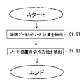
図2は、送信側で各ノードの切片方位を求める手順を示しており、
ステップ91:地図データから各ノード位置を抽出し、
ステップ92:各ノード位置の切片方位を抽出する。
【0038】
こうして抽出された各ノードの切片方位は、図3に示すように、各ノードの経度・緯度データとともに、形状データを表すノード列情報として纏められる。このノード列情報には、ノード列が表すベクトルデータの種別(この場合は「道路」)と、ノード総数(N個)と、ノード番号P1からの各ノードに関する経度・緯度データ及び切片方位データとが並ぶ。ノード番号P1の経度・緯度データ及び切片方位データは絶対座標及び絶対方位で表示されるが、ノード番号P2からノード番号PNまでの経度・緯度データ及び切片方位データは、データ量を減らすため、相対座標及び相対方位で表示される。
このノード列情報は、ノード列情報によって表された道路区間内の事象位置を表す相対位置データとともに伝送フォーマットに変換されて伝送される。
【0039】
ノード列情報及び相対位置データを受信した受信側は、マップマッチングを実施してノード列情報で表示された道路区間を特定する。図5は、このマップマッチングでの手順を示している。
ステップ121:ノード番号PXの経度・緯度データに近い道路上の位置を、近い順にマッチング候補として抽出し、
ステップ122:その候補位置の切片方位とPXの切片方位との差分を求める。その差分が規定値より小さければマッチング候補とし、図44で説明したマップマッチングの対象とする。
【0040】
また、差分が規定値より大きい場合には、それをマッチング候補から除外し、ステップ121に戻って、次ぎに近いものをマッチング候補として抽出し、ステップ122の手順を実行する。
【0041】
図1において、道路2上の地点PXは、最も近い道路である道路1に誤マッチングしやすいが、図4に示すように、受信側では、マッチングに際して、地点PXに最も近い道路1上のマッチング候補点1と地点PXとの切片方位を比較することにより、マッチング候補点1を候補から除外することができ、地点PXに次に近い道路2上のマッチング候補点2を候補として残すことができる。
【0042】
このように、この実施形態の位置情報伝達方法では、位置情報に切片方位情報を含めることにより、受信側でのマッチング精度を高め、短時間での候補の絞り込みを可能にする。そのため、受信側では、伝達されたデジタル地図上の位置を正確且つ迅速に認識することができる。
【0043】
なお、この実施形態では、道路形状を示す形状データに、道路のノード及び補間点の座標データを含める場合について説明したが、道路形状上で一定間隔ごとに座標点をリサンプルし、道路形状を示す形状データには、前記座標点の座標データを含めるようにしてもよい。
【0044】
(第2の実施形態)
第2の実施形態では、形状データに高さのデータを加えて伝達する位置情報伝達方法について説明する。
【0045】
図6は、デジタル地図データが、経度、緯度及び高さの3次元で表現されている場合の道路を表すベクトルデータ列を模式的に示している。
この場合、送信側は、形状データのノード列情報に、図7に示すように、各ノードのX方向座標(経度)、Y方向座標(緯度)及びZ方向座標(標高)を含めて受信側に伝達する。
【0046】
受信側では、第1の実施形態の切片方位情報と同様に、マッチングに際して、X−Y平面上の距離に基づいて選択したマッチング候補点のZ方向座標を参照することにより、候補点を絞り込むことができ、伝達されたデジタル地図上の位置を正確且つ迅速に認識することができる。
【0047】
なお、各ノードのZ方向座標は、標高で表したが、地表面からの高さで表示しても良い。このように、地表面からの高さのデータを形状データに含めることにより、高架道路と、その下を通る一般道路とを区別することが可能になる。
また、図8に示すように、各ノードのZ方向座標は、1つ手前のノードとの勾配で表示しても良い。
【0048】
(第3の実施形態)
第3の実施形態では、形状データを関数で近似して、伝達するデータ量を削減する位置情報伝達方法について説明する。
【0049】
図9(a)に示すP1からPnまでのベクトルデータ列の内、P1からPm1まで、及び、Pm1からPm2までの形状を、図9(c)に示すコサインカーブ等の基本関数F(h,r1,r2)で近似する。h,r1,r2は、この関数のパラメータである。
【0050】
この近似を行うことにより、図9(b)に示すように、P1からPm2までは、P1、Pm1及びPm2の座標データと、F(a,b,c)で示すP1〜Pm1間を近似した関数及びそのパラメータと、F(d,e,f)で示すPm1〜Pm2間を近似した関数及びそのパラメータとで表すことができ、データ量を削減できる。
図10は、この場合のノード列情報を示している。
【0051】
受信側では、この形状データを受信すると、P1とPm2との間は、P1、Pm1及びPm2の座標データとパラメータとからF(a,b,c)及びF(d,e,f)で表示された形状を求め、その形状の上に任意の間隔で地点を設定してマップマッチングを実施する。
この場合、F(a,b,c)及びF(d,e,f)で表される形状は、図9(a)のP1からPm1及びPm1からPm2までの形状と正確に一致しなくても、受信側で誤マッチングを生じない程度に近似していれば良い。
【0052】
この実施形態の位置情報伝達方法では、伝達するデータ量を大幅に削減することができ、データ伝送の効率化を図ることができる。
【0053】
(第4の実施形態)
第4の実施形態では、平行する道路の道路形状データを少ないデータ量で伝達する位置情報伝達方法について説明する。
【0054】
高速道路や有料道路は、図11に示すように、多くのデジタル地図において上下線分離道路で表現され、二条線と呼ばれている。この二条線の場合には、図12に示すように、一方の道路(道路2)の道路形状データは、他方の道路(道路1)の道路形状データを利用して、データ量を圧縮することができる。
【0055】
この場合、道路2のノード地点P1’、P2’、‥、Pn’は、道路1におけるノード地点P1、P2、‥、Pnを、道路1の右側(または左側)に、一定のオフセット距離(L)だけ移動した地点として近似することができる。オフセットする方向は、図13に示すように、道路1の各ノード地点P1、P2、‥、Pnの切片方向と直交する方向である。
【0056】
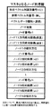
ノード列情報には、図14に示すように、先頭に、形状データの識別番号である形状ベクトル列識別番号と、参照すべき形状データを表す参照ベクトル列番号とを記述する。マスタとなる道路1のノード列情報では、参照ベクトル列番号は「無し」となり、各ノードについて、第1の実施形態と同様(図3)、経度・緯度データと切片方位データとを記述する。
【0057】
一方、道路1の形状データを参照する道路2のノード列情報は、図15に示すように、道路2の形状ベクトル列識別番号と、参照先の道路1の形状データを表す参照ベクトル列番号と、オフセット距離と、オフセット方向(マスタとなるノード列の右か左か)とを記述する。
【0058】
このように、平行する道路の場合には、一方の道路の道路形状データを利用して他方の形状データを表すことにより、伝送すべきデータ量を大幅に削減することができる。
【0059】
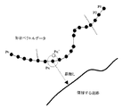
なお、この方式では、二条線の一方の実在する道路形状から、一定距離オフセットして、他方の道路を写像して再現しているが、この場合には、曲率の大きい急なカーブ部分で誤差が大きくなると云うウイークポイントを持つ。写像により再現される位置の誤差をできるだけ小さくするには、図16に示すように、二条線の中心線を求め、この実在しない「仮想の中心線形状ベクトルデータ列」をマスタとして送信し、上り路線及び下り路線の形状データは、両方とも、マスタを参照し、オフセット距離及びオフセット方向だけで規定するようにしても良い。
また、ここでは二条線について説明したが、多数の道路が並走する格子状道路を対象として、この実施形態の方式を適用することも可能である。
【0060】
(第5の実施形態)
第5の実施形態では、デジタル地図の著作権を損なうことが無いように、形状データを崩して伝達する位置情報伝達方法について説明する。
【0061】
デジタル地図は、その地図の制作者が独自の工夫を凝らして地図形状を設定しており、地図形状に対して制作者が著作権を有している。そのため、地図形状を形状データでそのまま伝達した場合には、デジタル地図の著作権を損なう虞れが発生する。この実施形態の位置情報伝達方法では、そうした懸念を除くため、元の地図形状を、受信側で誤マッチングが発生しない程度に、多少変形して伝達する。
【0062】
図17は、この場合の形状データの変形を模式的に示している。地図データの持つ本来の位置をPxとするとき、この位置をPx’の位置に変形する。このとき、PxからPx’までの距離(遷移値B)は、地点Pxから隣接する道路までの距離Lに基づいて設定し、また、PxからPx’への方位(遷移方位θ)は乱数で決定する。
【0063】
図18は、Px’を算出する手順を示している。
ステップ261:地図データからノード位置Pxを抽出して、
ステップ262:隣接道路までの距離Lを計算し、
ステップ263:遷移値Bを決定する。
【0064】
この遷移値Bの決定は、図19に示す手順により、
ステップ271:B=L×β1によりBを求める。ここで、β1は、あらかじめシステムで決めた1未満の値(例、β1=0.1)である。
ステップ272:ステップ271で求めたBをβ2と比較する。β2は、あらかじめシステムで決めた距離(例、β2=150m)である。B>β2であるときは、
ステップ273:B=β2と決定する。
また、ステップ272において、B≦β2であるときは、ステップ271で求めた値をBと決定する。
【0065】
こうして遷移値Bを決定すると、
ステップ264:遷移方位θを次式によって決定する。
θ=R×360 (度)
ここで、Rは乱数発生関数であり、0〜1の一様乱数である。なお、θは、真北の絶対方位を0度として、時計回りに0度〜360度の絶対方位を表現している。
ステップ265:決定した遷移値B及び遷移方位θを用いて、遷移後の座標Px’を計算する。
【0066】
こうした手順により、地図データを、受信側で誤マッチングが発生しない程度に、変形することができる。
【0067】
なお、地図データの変形方法としては、この他に、Pxの座標値に対して緯度方向に乱数Cを加算し、経度方向に乱数Dを加算して遷移後の座標Px’を求める方法、あるいは、本来の位置からの遷移値をσ=Aの正規分布となるように乱数で決定する方法などを用いることもできる。
【0068】
(第6の実施形態)
第6の実施形態では、形状データで特定した道路区間の中の相対位置を、この道路区間の中に適宜定義した基準点を用いて特定し、この情報を伝達する位置情報伝達方法について説明する。
【0069】
図20に示すように、形状データによりP1からPnまでのノード列を伝達し、この中の事故位置を伝える場合に、この実施形態の方法では、ノード列の途中の交差点のノードP4を基準点に取り、P4からの相対距離によって事故位置を表示する。
また、この道路区間に発生している渋滞を、T字路のノードPxを基準点に取り、Pxからの相対距離によって表示する。
このように、道路区間内に定義した基準点を用いて表示する相対位置情報は、図21に示すデータによって受信側に伝達される。
【0070】
図21(a)は、道路区間を特定するノード列情報である。図21(b)は、特願平11−242166号で提案している道路付加情報であり、対象とする道路の道路種別コード、道路番号、有料道路コードとともに、この道路区間に含まれる交差点ノードに関して、ノード列情報にリンクするノード番号、その交差点ノードの接続リンク数、各接続リンクの接続リンク角度が、それぞれの交差点ノードごとに表示されている。
【0071】
図21(c)は、道路区間内の相対位置と、その位置で発生している事象の事象内容とを表示する事象情報であり、相対位置は、基準点を明示し、そこからの相対距離で表示される。
【0072】
このように、送信側が、道路区間内の交差点などの識別し易いノードを基準点として定義することにより、受信側では、事象発生位置を的確に把握することが可能になる。
【0073】
(第7の実施形態)
第7の実施形態では、各ノード情報と当該ノードでの発生事象とを直接関連付けて表示し、伝達する位置情報伝達方法について説明する。
【0074】
この方法では、図22(a)に示すように、ノード列情報の中で、各ノード番号の座標データに続けて、当該ノードで発生している該当事象を該当事象コードで記述し、図22(b)に示すように、各該当事象コードで表した事象内容を事象詳細情報として記述する。
あるいは、図23(a)に示すように、ノード列情報には、ノード番号と座標データとだけを記述し、図23(b)に示すように、事象情報として、事象内容と、その事象が発生しているノード番号とを記述する。
この方法では、受信側において、事象発生位置を高精度に再現することができる。
【0075】
(第8の実施形態)
第8の実施形態では、道路上の位置情報を、車両の進行方向の情報を含めて伝達する位置情報伝達方法について説明する。
例えば、道路上の事故が上り車線の走行にだけ影響し、下り車線には影響しない場合がある。こうしたとき、交通情報では、事故発生位置と、事故の影響を受ける車線の情報とを伝達する必要がある。
【0076】
図24は、道路上で、車両進行方向1の方向に走行している車両が影響を受ける事象A(通行止)と、車両進行方向2の方向に走行している車両が影響を受ける事象B(車線規制)とが発生している状態を模式的に示している。
【0077】
このとき、道路上の位置情報は、図25に示すデータによって受信側に伝達される。
図25(a)は、道路区間を特定するノード列情報である。このノード列情報では、ノード列の並び順に対する順方向を2、ノード列の並び順に対する逆方向を1とする方向定義が規定されている。図25(b)は、第6の実施形態(図21)と同様の道路付加情報である。
【0078】
図25(c)は、事象情報であり、各事象について、事象内容、及び基準点からの相対距離とともに、その事象が影響を与えている車両進行方向を、方向定義を示す方向識別フラグにより表示している。即ち、事象Aは、車両進行方向1の方向に走行する車両が影響を受けるため、方向識別フラグには、逆方向を定義する1が表示され、事象Bは、車両進行方向2の方向に走行する車両が影響を受けるため、方向識別フラグには、順方向を定義する2が表示される。
【0079】
このデータを受信した受信側では、ノード列情報で表示されたノードP1、P2、‥、Pnの一方向の配列に対するマップマッチングで道路区間を特定し、事象情報に記述された相対情報と方向識別フラグの情報とに基づいて、道路区間内の事象発生位置を、車両進行方向を含めて特定することができる。そのため、一方向の形状データで両方向の事象を表現することが可能になり、データ量の圧縮が可能となる。
【0080】
また、この方向識別フラグは、第4の実施形態で説明した二条線の一方で発生した事象を記述する場合にも使用することができ、図29に示すように、形状ベクトル列識別番号123の道路(図14)を写像して再現した、形状ベクトル列識別番号124の道路(図15)で発生した事象であることを、方向識別フラグ(=1)により表示することができる。なお、この道路での事象情報は、ノード番号として写像後のノード番号(Pn’)を使用して表示する。
【0081】
また、方向識別フラグは、形状データで特定する道路区間の一方通行を表示する場合にも使用することができ、図26に示すように、ノード列の並び順に対して、順方向を1、逆方向を2と方向定義した場合、形状データで特定される道路区間がPn→P1方向の一方通行であるとき、図27に示すように、ノード列情報に一方通行方向を2と指定する方向識別フラグを記述して、一方通行情報を表示することができる。なお、一方通行で無い場合は、0(=一方通行無し)で表示する。
【0082】
このノード列情報を受信した受信側では、マップマッチングに際して、図28に示すように、
ステップ341:ノード列情報を受信し、
ステップ342:マップマッチングを実施して、マッチング候補の道路地点を抽出する。
ステップ343:その候補地点の地図データ上での一方通行の指定と、ノード列情報の一方通行方向情報とを比較する。それらが一致するときは、そのマッチング候補を残し、不一致であるときは、マッチング候補から除外して、ステップ342に戻り、次ぎのマッチング候補を抽出する。
【0083】
このように、方向識別フラグを使用することにより、一方通行の情報や、発生した事象が影響を及ぼす車両進行方向の情報などを、少ないデータ量で伝達することができる。
【0084】
(第9の実施形態)
第9の実施形態では、交通情報として、2地点間の旅行時間を伝える位置情報伝達方法について説明する。
【0085】
この方法では、図30に示すように、2つの基準点(P4、Px)を設定し、この基準点間の旅行時間を図31に示すデータで伝達する。
図31(a)は、この2つの基準点を含む道路区間を特定するためのノード列情報である。図31(b)は、第6の実施形態で説明した図21(b)と同様の道路付加情報である。図31(c)は、旅行時間を表示する所要時間情報であり、始端側ノード番号(P4)、終端側ノード番号(Px)及びその間の旅行時間が記述される。
【0086】
この情報を受信した受信側では、ノード列情報及び道路付加情報を用いて、マップマッチングで道路区間を特定し、所要時間情報から、基準点間の旅行時間を認識することができる。
【0087】
(第10の実施形態)
第10の実施形態では、データ圧縮された位置情報を受信した受信側で、マップマッチングがし易いベクトルデータ列を再生する方法について説明する。
【0088】
図32は、位置情報を受信して再生し、また、事象発生を知らせる位置情報を生成して送信する位置情報送受信装置10を示している。
この装置10は、他の装置20の位置情報送信部21から送られた位置情報を受信する位置情報受信部11と、この位置情報に含まれる形状データをマップマッチングがし易いベクトルデータ列に変換するノード列復元部12と、デジタル地図データを蓄積するデジタル地図データベース14と、マップマッチングを実施して位置情報で表された道路区間を特定するマップマッチング部13と、位置情報で表された道路区間と事象位置とを表示するデジタル地図表示部15と、発生した事象情報を入力する事象入力部16と、事象発生位置を伝達するための位置情報を生成する位置情報変換部17と、生成された位置情報を他の装置20の位置情報受信部22に送信する位置情報送信部18とを備えている。
【0089】
この装置10では、位置情報受信部11が位置情報を受信し、ノード列復号部12が、そこに含まれる関数近似や間引きによりデータ圧縮された形状データを等間隔の形状ベクトルデータ列に変換する。図33(a)は、圧縮前の形状ベクトルデータ列を示し、図33(b)は、間引き及び関数近似により圧縮されたデータを示している。ノード列復号部12は、この図33(b)のデータから、図33(c)に示すように、等間隔の形状ベクトルデータ列を復元する。
【0090】
マップマッチング部13は、デジタル地図データベース14に蓄積された地図データから、復元された形状ベクトルデータ列にマッチングする道路区間を検出し、また、この道路区間の事象発生位置を位置情報から特定して、デジタル地図表示部15にそれらを表示する。
また、事象情報入力部16から事象情報が入力されると、位置情報変換部17は、事象発生位置を含む道路区間と、この道路区間内の事象発生位置とを指定する位置情報を生成し、この位置情報が位置情報送信部18から送信される。
【0091】
このノード列復元部12の具体的な動作について説明する。
送信側では、地図データから図33(a)に示す形状ベクトルデータ列を取得すると、その一部の形状ベクトルデータ列を関数Fで近似し、また、直線的な部分はデータを間引き、こうしてデータ量を圧縮したデータを送信する。
【0092】
なお、関数Fで近似する方法については第3の実施形態で説明した。また、データを間引く方法については、特願平11−242166号に詳しく説明している。要は、道路区間に含まれるノードの中で、マップマッチングへの貢献度が低いノードを間引くのであり、そのため、隣接するノードから当該ノードへの方位に対して、当該ノードから次のノードへの方位の変化が所定角度以下であり、且つ、前記隣接するノードから当該ノードまでの距離が所定距離未満である場合に、当該ノードは間引かれる。
【0093】
こうした圧縮されたデータを受けて、ノード列復元部12は、次のようにして、等間隔のデータを復元する。ここでは、各間隔が、一定距離A(メートル)から±b(メートル)以上ずれないように復元している。
【0094】
データが間引かれている区間では、Pn-1(Xn-1,Yn-1)とPn(Xn,Yn)との間は直線と見なし、Aメートル間隔でポイントを生成する。この模様を図47に示している。
ここで、Pn-1→Pnベクトルの真北(Y方向)からの方位をθとし、生成するポイントをPnm(m=1,2,3,‥)とすると、
Xnm=Xn-1+m×(Asinθ)
Ynm=Yn-1+m×(Acosθ)
となる。
【0095】
また、図9(c)の基本関数Fで関数近似されている区間では、図48に示すように、Pn-1→Pn間を直線と想定した場合のL’(初回はL'=A−b)進んだ位置Pn1'(Xn1',Yn1')を算出する。このとき、Pn1’の座標は、
Xn1’=Xn-1+1×(L’sinθ)
Yn1’=Yn-1+1×(L’cosθ)
となる。Pn1'に対応する関数F上の点をPn1(=F(Pn1’))とする。Pn-1→PnをX’軸、Pn-1を通りX’軸に直交する軸をY’軸とするX'-Y’座標系の下で、Pn1のX’座標はL’、Pn1のY’座標はF(1×L')である。このX'-Y’座標系を角度(90−θ)だけ回転して、その座標値をX-Y座標系の座標値に変換すると、Pn1(Xn1,Yn1)の座標は、
Xn1 =Xn1’+{F(1×L’)sin(θ−90)}
Yn1 =Yn1’+{F(1×L’)cos(θ−90)}
となる。
【0096】
ここで、Pn-1→Pn1間の距離Ln1が、A+b(メートル)以内の時は、Pn2の算出に進む。Pn-1→Pn1間の距離Ln1が、A+b(メートル)より大きい時は、L’=L’/2として再計算する。
以降は、このバイナリサーチの算出方法を繰り返す。
【0097】
ノード列復元部12のこのような処理により、圧縮されていたデータは等間隔の座標列に変換される。そのため、マップマッチング部13のマッチング処理が容易になる。
【0098】
このノード列復元部12の処理は、ソフトウエアによって実現しても良いし、IC化したハードウエアで実現しても良い。
【0099】
このように、この実施形態の方法では、データ圧縮されたデータ列から、等間隔のデータ列を復元しているため、マッチング処理が容易になり、マップマッチングの精度を高めることができる。
【0100】
(第11の実施形態)
第11の実施形態では、デジタル地図データの道路以外の形状を伝達する位置情報伝達方法について説明する。
【0101】
デジタル地図データには、図34に示すように、施設形状を表すベクトル列(V)や、図35に示すように、県境形状を表すベクトル列(X)、湖沼形状を表すベクトル列(Y)、等高線形状を表すベクトル列(W)などが含まれる。これらの形状は、これまで説明して来た道路形状の表示方法を利用して表示し、また、その事象位置を特定することができる。
【0102】
図36は、家屋形状を表す形状データを示している。形状ベクトル種別には家屋と記述し、詳細情報として、ビル、一般家屋などの識別コードを記述する。次いで、ノード総数と家屋形状を表す各ノード座標とを記述し、事象発生位置を、先頭のノード位置からの相対距離で規定する。
【0103】
図37は、水系形状を表す形状データを示している。形状ベクトル種別には水系と記述し、詳細情報として、湖などの面表現水系、河川などの線表現水系の識別コードを記述する。その他は家屋形状の場合と同じである。
図38は、行政界形状を表す形状データを示している。形状ベクトル種別には行政界と記述し、詳細情報として、都道府県境、市区町村境、町丁目境の識別コードを記述する。
また、図39は、等高線形状を表す形状データを示している。形状ベクトル種別には等高線と記述し、詳細情報として、海抜何メートル等高線の識別コードを記述する。
【0104】
こうした位置情報を伝達することにより、送信側と受信側とで異種のデジタル地図を装備している場合でも、家屋、水系、行政界、等高線などを相互に同定し、事象発生位置を伝え合うことができる。
【0105】
(第12の実施形態)
第12の実施形態では、デジタル地図上の道路以外の位置を伝達する位置情報伝達方法について説明する。
【0106】
図40に示すように、デジタル地図上の黒三角形で示す道路外の位置(再現位置)を伝達する場合、送信側は、道路上に位置する三つの基準点(事象点1、事象点2、事象点3)を設定し、事象点1を含む道路区間(マップマッチングデータ1)の形状データ、事象点1から再現位置までの距離r1及び方位θ1のデータ、事象点2を含む道路区間(マップマッチングデータ2)の形状データ、事象点2から再現位置までの距離r2及び方位θ2のデータ、並びに、事象点3を含む道路区間(マップマッチングデータ3)の形状データ、事象点3から再現位置までの距離r3及び方位θ3のデータを受信側に伝達する。
【0107】
受信側では、図41に示す手順で再現位置を再現する。
ステップ481:マップマッチングデータ1を用いてマップマッチングを実行し、
ステップ482:道路上の事象点1を特定する。
ステップ483:事象点1から距離r1、方位θ1にある地点P1を求める。
同様の手順を繰り返して、マップマッチングデータ2から事象点2を特定し、事象点2から距離r2、方位θ2にある地点P2を求め、マップマッチングデータ3から事象点3を特定し、事象点3から距離r3、方位θ3にある地点P3を求める。
ステップ484:点P1、P2、P3の重心を算出し、
ステップ489:重心位置を再現位置とする。
【0108】
また、3つの事象点は、図42に示すように、一本の道路(マップマッチングデータ)上に設定しても良い。この場合、各々事象点から見た再現位置は、x座標及びy座標の差分データ(Δxn、Δyn)を用いて表すことができる。
【0109】
この位置情報を受信した受信側では、図43に示す手順で再現位置を再現する。
ステップ501:マップマッチングデータを用いてマップマッチングを実行し、
ステップ502:道路上の事象点1を特定し、
ステップ503:事象点1からΔx1、Δy1の地点P1を求める。
【0110】
同様に、ステップ502及びステップ503を繰り返し、事象点2からΔx2、Δy2の地点P2、及び事象点3からΔx3、Δy3の地点P3を求める。
ステップ504:点P1、P2、P3の重心を算出し、
ステップ505:重心位置を再現位置とする。
【0111】
こうして、道路以外の位置を表すことができる。なお、マップマッチングデータとしては、道路以外に、第3の実施形態で説明した施設形状を表すベクトル列や、県境形状を表すベクトル列、湖沼形状を表すベクトル列、等高線形状を表すベクトル列などを用いることもできる。
【0112】
なお、ここでは、三つの基準点から目標位置までの相対情報(距離及び方位の情報)を伝達する場合について示したが、送信側から、二つの基準点、あるいは、一つの基準点からの相対情報しか伝えなかった場合でも、受信側では、その基準点を自己のデジタル地図上で高精度に特定することができるため、その基準点からの相対情報により、目標位置を統計的に求めることが可能である。
【0113】
また、各実施形態では、形状データに含める各ノードの座標データを経度・緯度データの絶対値または相対値で表しているが、各ノードの座標データは、他のパラメータを用いて表しても良い。
【0114】
例えば、図49に示すように、xy座標により(xj-1,yj-1)、(xj,yj)及び(xj+1,yj+1)で表されるノードPj-1、Pj及びPj+1が存在し、直線Pj-1→Pjの距離がLj、直線Pj-1→Pjの絶対方位(北を基準とした時計回り方向の角度)がωj-1、直線Pj→Pj+1の距離がLj+1、直線Pj→Pj+1の絶対方位がωjであるとすると、ノードPjは、前ノードPj-1からの距離Ljと絶対方位ωj-1とを用いて特定することができる。
【0115】
ここで、Lj及びωj-1は、Pj-1及びPjのxy座標値から次式により算出することができる。
Lj =√{(xj−xj-1)2+(yj−yj-1)2}
ωj-1=tan-1{(xj−xj-1)/(yj−yj-1)}
ノードPj+1についても、同様に、前ノードPjからの距離Lj+1と絶対方位ωjとを用いて特定することができる。
【0116】
また、ノードPj+1は、前ノードPjからの距離Lj+1と偏角、つまり、Pj→Pj+1の絶対方位ωjとPj-1→Pjの絶対方位ωj-1との変位差Θj、を用いて特定することもできる。偏角Θjは、Pj-1、Pj及びPj+1の各xy座標値から次式により算出することができる。

図50は、形状データに含まれるノード列情報を、前ノードからの距離と偏角とを用いて表した送信データを例示している。図50(a)の送信データは、ノードp1とノードp2との間の補間点#1〜#aのデータを含み、この補間点のデータが、前ノードまたは前補間点からの距離と偏角とのデータで構成されている。始端となるノードp1に関しては、位置を表す絶対座標(経度、緯度)と、切片方向絶対方位(p1と補間点#1とを結ぶ直線の絶対方位)とのデータを含んでいる。また、補間点#1のデータは、補間点#1から補間点#2に延びる直線の絶対方位と前記切片方向絶対方位との方位差を表す偏角データと、p1から補間点#1までの距離データとで構成され、補間点#2のデータは、同様に、補間点#2から補間点#3に延びる直線の絶対方位と補間点#1から補間点#2に延びる直線の絶対方位との偏角データと、前補間点#1から補間点#2までの距離データとで構成されている。補間点#3〜#aに関しても同様である。
【0118】
また、図50(b)の送信データは、始端のノードp1を除く各ノードのデータが、前ノードからの距離と偏角とで構成されている。
【0119】
図51は、元地図データの対象道路区間の形状(a)と、それを前ノードからの距離と偏角とで表した座標列(b)とを模式的に示している。なお、図51に示すように、対象道路区間の元地図データから、対象道路区間の形状を、より少ない数で再現できるノードをリサンプルし、リサンプルしたノードを前ノードからの距離と偏角とで表現するようにしても良い。
【0120】
図52は、この送信データを受信した受信側でのマップマチング処理を模式的に示している。このマップマチングでは、自己のデジタル地図上で、まず、形状データの始端ノードp1に対応する候補点を設定する。そのために、始端ノードp1の緯度・経度データ位置から、概ね200m以内にあるn個の近隣道路上にn個の候補点を設定する。
次に、始端ノードp1位置から各候補点P1,iまでの距離Diを算出する。
【0121】
次に、図53に示すように、各道路の現在の候補点Pj,iから、道路に沿って、形状データのpj→pj+1間の距離Ljだけ進んだ点Pj+1,iを求め、Pj-1,i→Pj,iを結ぶ直線とPj,i→Pj+1,iを結ぶ直線とのなす角θj,iと、形状データで表されたpjの相対方位Θjとの差|Δθj,i|を算出し、次式により評価値εj,iを算出する。
εj,i = α×Di+Σ(β×|Δθj,i|)
(Σはj=1からjまで加算)
α:予め決めた係数
β:予め決めた係数
次いで、候補点Pj,iを候補点Pj+1,iに移動する。
【0122】
こうした処理を全ての候補点について繰り返し、また、同様の処理を、形状データに含まれる全てのノードについて実行する。形状データに含まれた全てのノードについての処理が終了すると、評価値εiの最も小さい候補を対象道路として選択する。
【0123】
このマップマッチング処理では、形状データに含まれる「前ノードからの距離Li」を用いて、次の候補点を容易に求めることができ、また、形状データに含まれる「相対方位」を直接用いて、評価値を算出することができる。そのため、受信側でのマップマッチングの処理負担が軽減される。
【0124】
また、本発明の位置情報伝達方法は、送信側及び受信側装置のコンピュータの動作手順をプログラムにより規定して実現することができる。
【0125】
【発明の効果】
以上の説明から明らかなように、本発明のデジタル地図の位置情報伝達方法では、デジタル地図上の位置を効率的、且つ、正確に伝達することができる。
【0126】
形状データに、方位情報や高さ情報、方向識別フラグによる一方通行情報などを付加して伝達する方法では、マッチング精度を高め、マッチングの所要時間を短縮することが可能になる。
【0127】
また、形状データ列を関数で近似したり、二条線の形状データをオフセット距離で表示する伝達方法では、データ量を減らし、データ伝送効率を高めることができる。
【0128】
また、道路区間内の交差点などに基準点を設定して事象位置までの相対距離を表示したり、ノード番号で事象位置を規定する伝送方法では、受信側での事象位置の特定精度を高めることができる。
【0129】
また、方向識別フラグを用いることにより、事象の影響が及ぶ車両進行方向を特定することができる。
【0130】
また、圧縮されている形状データ列から等間隔のデータを復元する方法及び装置では、受信側でのマッチング効率を高めることができる。
【0131】
また、本発明の伝達方法では、旅行時間を伝達したり、また、地図データの著作権を損なわない形でのデータを伝達したりすることも可能である。
【0132】
また、本発明は、道路以外のベクトルデータの伝達にも応用することができ、また、デジタル地図上の道路外の位置を伝達することもできる。
【図面の簡単な説明】
【図1】第1の実施形態の形状データを説明する図、
【図2】第1の実施形態の送信側での形状データの生成手順を示すフロー図、
【図3】第1の実施形態でのノード列情報を示す図、
【図4】第1の実施形態での受信側のマップマッチングを説明する図、
【図5】第1の実施形態での受信側のマップマッチング手順を示すフロー図、
【図6】第2の実施形態の形状データを説明する図、
【図7】第2の実施形態でのノード列情報を示す図、
【図8】第2の実施形態での別の表現方法を取るノード列情報を示す図、
【図9】第3の実施形態におけるデータ削減を示す図、
【図10】第3の実施形態でのノード列情報を示す図、
【図11】二条線の説明図、
【図12】第4の実施形態での形状データを説明する図、
【図13】第4の実施形態でのオフセットの方向を説明する図、
【図14】第4の実施形態でのマスタ側のノード列情報を示す図、
【図15】第4の実施形態でのマスタを参照する側のノード列情報を示す図、
【図16】第4の実施形態での別の方式による形状データを説明する図、
【図17】第5の実施形態での形状データを説明する図、
【図18】第5の実施形態での形状データの生成手順を示すフロー図、
【図19】第5の実施形態での遷移値の決定手順を示すフロー図、
【図20】第6の実施形態での基準点を説明する図、
【図21】第6の実施形態でのノード列情報、道路付加情報、事象情報を示す図、
【図22】第7の実施形態でのノード列情報及び事象詳細情報を示す図、
【図23】第7の実施形態でのノード列情報及び事象情報を示す図、
【図24】第8の実施形態での事象発生状況を説明する図、
【図25】第8の実施形態でのノード列情報、道路付加情報、事象情報を示す図、
【図26】第8の実施形態での一方通行状況を説明する図、
【図27】第8の実施形態で一方通行を表示するノード列情報を示す図、
【図28】第8の実施形態でのマップマッチング手順を示すフロー図、
【図29】第8の実施形態での二条線の事象を表す事象情報を示す図、
【図30】第9の実施形態での旅行時間を説明する図、
【図31】第9の実施形態でのノード列情報、道路付加情報、所要時間情報を示す図、
【図32】第10の実施形態における位置情報送受信装置の構成を示すブロック図、
【図33】第10の実施形態での形状データの圧縮、復号を説明する図、
【図34】デジタル地図での施設形状ベクトルを示す図、
【図35】デジタル地図での県境形状、等高線、湖沼形状を表すベクトルを示す図、
【図36】第11の実施形態での家屋形状のノード列情報を示す図、
【図37】第11の実施形態での水系形状のノード列情報を示す図、
【図38】第11の実施形態での行政界形状のノード列情報を示す図、
【図39】第11の実施形態での等高線形状のノード列情報を示す図、
【図40】第12の実施形態での道路外位置表現方法を説明する図、
【図41】第12の実施形態での位置再現手順を示すフロー図、
【図42】第12の実施形態での別の道路外位置表現方法を説明する図、
【図43】第12の実施形態での別の位置再現手順を示すフロー図、
【図44】マップマッチングの一例を説明する図、
【図45】道路形状データ及び相対位置情報を説明する図、
【図46】切片方位を説明する図、
【図47】第10の実施形態において直線近似された区間でのデータ復元方法を説明する図、
【図48】第10の実施形態において関数近似された区間でのデータ復元方法を説明する図、
【図49】ノード座標を前ノードとの距離及び偏角で表す方法を説明する図、
【図50】ノード座標を前ノードとの距離及び偏角で表したノード列情報を示す図、
【図51】ノード座標を前ノードとの距離及び偏角で表した形状データを模式的に示す図、
【図52】ノード座標を前ノードとの距離及び偏角で表したときのマップマチング処理を模式的に示す図、
【図53】ノード座標を前ノードとの距離及び偏角で表したときのマップマチング処理において、次の候補点の求め方を示す図である。
【符号の説明】
10、20 位置情報送受信装置
11、22 位置情報受信部
12 ノード列復元部
13 マップマッチング部
14 デジタル地図データベース
15 デジタル地図表示部
16 事象入力部
17 位置情報変換部
18、21 位置情報送信部[0001]
BACKGROUND OF THE INVENTION
The present invention relates to a method for transmitting position information of a digital map and an apparatus used therefor, and in particular, it enables to transmit the position on a digital map efficiently and accurately.
[0002]
[Prior art]
In recent years, the number of vehicles equipped with on-vehicle navigation devices has increased rapidly. The navigation in-vehicle device maintains a digital map database, displays traffic jams and accident locations on a map based on traffic jam information and accident information provided by traffic information centers, etc., and adds such information to conditions Perform route search.
[0003]
The digital map database is created by several companies in Japan, but due to differences in the base chart and digitizing technology, this map data contains errors, and the errors differ depending on the digital map of each company.
For example, when the accident location is reported in traffic information, if the longitude / latitude data of that location is presented separately, the vehicle-mounted device identifies the location on the different road as the accident location, depending on the type of digital map database it holds. There is a risk of it.
[0004]
In order to improve this inaccuracy of information transmission, conventionally, node numbers are defined for nodes such as intersections in the road network, and link numbers are defined for links representing roads between nodes. In the map database, each intersection or road is stored in association with the node number and link number. In the traffic information, the road is identified by a link number, and the number of meters from the head is used to express the points on the road. Is displayed.
[0005]
However, node numbers and link numbers defined in the road network need to be replaced with new ones as roads are newly established or changed. When node numbers or link numbers are changed, each company's digital map data is also updated. Must. Therefore, the method of transmitting the position information of the digital map using the node number or the link number requires a great social cost for the maintenance.
[0006]
In order to improve such points, the inventors of the present invention show the road shape of a road section of a predetermined length including the road position in order to convey the road position in Japanese Patent Application No. 11-2114068. "Road shape data" consisting of a coordinate sequence and "relative position data" indicating the road position in the road section represented by this road shape data are transmitted. Using the map matching, specifying the road section on the digital map, and using the relative position data to propose the method of specifying the road position in the road section, and in Japanese Patent Application No. 11-242166, The road type, road number, and number of cross links of nodes in a road section so that map matching on the receiving side can be performed accurately even if the amount of transmission data of “road shape data” is reduced. Proposed a method to transmit "additional information" such as intersection link angle, intersection name, etc., and a method to thin out the transmission data amount of "road shape data" within a range that does not cause erroneous matching on the receiving side. ing.
[0007]
In this case, the map matching on the receiving side is performed as follows, for example.
As shown in FIG. 45, as “road shape data” representing the road shape of the road where traffic jam occurs in the section A to B, the point P 0 (X 0 , Y 0 ), P 1 (X 1 , Y 1 ), P k (X k , Y k ) Longitude / latitude data
(X 0 , Y 0 ) (X 1 , Y 1 ) (X k , Y k )
, The receiving side uses the map data read from its own digital map database as shown in FIG. 0 (X 0 , Y 0 ) Select roads included in the error range centered on the point as candidates, and narrow down the candidates using the transmitted “additional information”. When candidates are narrowed down to one, (x 0 , Y 0 ) And (x k , Y k ) And the section is defined as a road section represented by “road shape data”.
[0008]
If the candidate cannot be narrowed down to one and roads Q and R remain as candidates, P 0 (X 0 , Y 0 ) Position Q on each candidate road closest to 0 , R 0 For P 0 ~ Q 0 , P 0 ~ R 0 Calculate the distance between them. This operation is P 1 (X 1 , Y 1 ), P k (X k , Y k ) For each point P and each point P 0 , P 1 , ..., P k The road section having the smallest sum of the root mean square distances is obtained, and the road section is specified by a method such as a road section represented by the “road shape data”.
The traffic jam sections A to B are specified based on the transmitted “relative position data” starting from the start position of the road section obtained from “road shape data”.
[0009]
[Problems to be solved by the invention]
When transmitting location information on a digital map, such as traffic information, it is necessary to transmit data so that the correct location can be recognized in a short time.
In addition, because it is assumed that the location information on the digital map is transmitted, such as information on distress sites in mountains and river accidents, it is assumed that map information other than roads and location information on points other than on roads are used. It is also necessary to communicate.
[0010]
The present invention responds to these problems, and “shape data” for specifying a map shape on a digital map and “relative position data” for specifying a relative position in the map shape specified by the “shape data”. Can be used to further improve the method of transmitting the location information of the digital map, and to transmit the location on the digital map efficiently and accurately. An object of the present invention is to provide a digital map position information transmission method that can also transmit information, and to provide a device used for the method.
[0011]
[Means for Solving the Problems]
Therefore, in the present invention, the transmitting side transmits position information including coordinate sequence information for specifying a vector shape on the digital map, and the receiving side performs map matching based on the coordinate sequence information to perform the vector shape on the digital map. In the position information transmission method for identifying the coordinate information, the coordinate direction information included in the coordinate sequence information is added to the coordinate sequence information for transmission.
[0012]
In addition, information on the height of the coordinate point included in the coordinate sequence information is added to the coordinate sequence information and transmitted.
[0013]
Further, the coordinate string information is configured to include position information of coordinate points and information of a function that approximates a vector shape passing through the coordinate points.
[0014]
In addition, the coordinate sequence information includes information specifying the coordinate sequence information of the reference destination and information specifying the distance and direction of the offset with respect to the coordinate sequence information of the reference destination.
[0015]
In addition, the coordinate values of the digital map representing the vector shape are included in the coordinate string information by making a transition within a range in which erroneous matching does not occur.
[0016]
Further, relative position information from a reference point set in the middle of the vector shape is included in the position information.
[0017]
Further, event information directly associated with the coordinate points of the coordinate string information is included in the position information.
[0018]
In addition, a direction identification flag is included in the position information, and a vehicle traveling direction affected by an event occurring on the road is displayed by the direction identification flag.
[0019]
In addition, a direction identification flag is included in the coordinate string information, and the one-way restricted state of the road specified by the coordinate string information is displayed by the direction identification flag.
[0020]
In addition, a plurality of reference points are set in the road shape, and information on travel time between the reference points is included in the position information.
[0021]
Further, a vector shape other than a road is specified by the coordinate string information.
[0022]
In addition, the position information is transmitted including coordinate sequence information and reference point relative position information for specifying one or more reference points, and relative position information of the target position with respect to the reference points. Map matching is performed based on column information to identify a vector shape on the digital map, and a reference point position in the vector shape is specified using reference point relative position information, and a relative position of a target position with respect to the reference point The target position is specified using information.
[0023]
On the receiving side, coordinate sequence information of coordinate points at equal intervals is restored from the coordinate sequence information, and map matching is performed using the restored coordinate sequence information.
[0024]
In addition, a coordinate sequence restoration device is constructed that restores coordinate sequence information of coordinate points at equally spaced intervals from coordinate sequence information that has been compressed to specify a vector shape on a digital map.
[0025]
According to the digital map position information transmission method of the present invention, the position on the digital map can be transmitted efficiently and accurately.
[0026]
By adding slice direction information, height information, one-way information based on a direction identification flag, and the like to the coordinate string information, the matching accuracy can be improved and the time required for matching can be shortened. .
[0027]
Further, by approximating the vector shape with a function or displaying the shape data of the vertical line separation road with the offset distance, the data amount can be reduced and the data transmission efficiency can be increased.
[0028]
In addition, by setting a reference point at an intersection in a road section and displaying the relative distance to the event location, or by specifying the event location with a node number, the accuracy of event location identification on the receiving side can be improved. it can.
[0029]
In addition, the vehicle traveling direction affected by the event can be specified using the direction identification flag.
[0030]
Further, the travel time can be transmitted, and the data can be transformed and transmitted without damaging the copyright of the map data.
[0031]
Further, it can be applied to transmission of vector data other than roads, and can also transmit positions outside roads on a digital map.
[0032]
In addition, the method and apparatus for restoring equally spaced data from the compressed shape data sequence can increase the matching efficiency on the receiving side.
[0033]
DETAILED DESCRIPTION OF THE INVENTION
(First embodiment)
In the first embodiment, a position information transmission method for increasing the map matching accuracy for specifying the road section on the receiving side by adding the intercept direction information to the shape data and transmitting the shape data will be described.
[0034]
P of
[0035]
The longitude data and the latitude data of each node are stored in the digital map database on the transmission side and the reception side. As described above, the data includes errors.
The transmitting side adds P to the shape data indicating the road shape. 1 , P 2 , ..., P N In order to reduce the amount of data, 1 The longitude / latitude data is displayed in absolute coordinate values (longitude, latitude) and P 2 , ..., P N Longitude / latitude data of P 1 The relative coordinate value indicating the difference from the longitude / latitude data of the current node or the relative coordinate value indicating the difference from the longitude / latitude data of the previous node is displayed.
[0036]
The section orientation information included in the shape data is the section orientation at each node position, that is, the node p, as indicated by the dotted arrow in FIG. x Is information on the direction of the tangent line that touches the road curve.
As shown in FIG. 46, the intercept azimuth at this node position is displayed in the range of 0 to 360 degrees clockwise with the absolute north azimuth being 0 degrees. Node p x The intercept orientation of is the node p x P is an adjacent node located upstream of x-1 , Node p x P is an adjacent node located downstream of x + 1 Node p x-1 And node p x Direction of the line connecting x-1 And node p x And node p x + 1 Direction of the line connecting x And
(Θ x-1 + Θ x ) / 2
It can ask for.
[0037]
FIG. 2 shows a procedure for obtaining the intercept direction of each node on the transmission side.
Step 91: Extract the position of each node from the map data
Step 92: Extract the intercept direction of each node position.
[0038]
As shown in FIG. 3, the intercept directions of the nodes extracted in this way are collected as node sequence information representing shape data together with the longitude / latitude data of each node. The node string information includes the type of vector data (in this case, “road”) represented by the node string, the total number of nodes (N), and the node number P 1 The longitude / latitude data and the intercept direction data for each node are arranged. Node number P 1 The longitude / latitude data and intercept direction data are displayed in absolute coordinates and absolute direction. 2 To node number P N In order to reduce the amount of data, the longitude / latitude data and the intercept orientation data up to are displayed in relative coordinates and relative orientation.
This node sequence information is transmitted after being converted into a transmission format together with relative position data representing the event position in the road section represented by the node sequence information.
[0039]
The receiving side that has received the node sequence information and the relative position data performs map matching to identify the road section displayed by the node sequence information. FIG. 5 shows the procedure in this map matching.
Step 121: Node number P X The location on the road that is close to the longitude / latitude data of
Step 122: intercept direction and P of the candidate position X Find the difference from the intercept direction. If the difference is smaller than the specified value, it is determined as a matching candidate, and is the target of map matching described in FIG.
[0040]
If the difference is larger than the specified value, it is excluded from the matching candidates, the process returns to step 121, the next closest one is extracted as a matching candidate, and the procedure of step 122 is executed.
[0041]
In FIG. 1, a point P on the
[0042]
As described above, in the position information transmission method of this embodiment, by including the intercept direction information in the position information, matching accuracy on the receiving side is improved, and candidates can be narrowed down in a short time. Therefore, the receiving side can accurately and quickly recognize the transmitted position on the digital map.
[0043]
In this embodiment, the case where the coordinate data of the road node and the interpolation point is included in the shape data indicating the road shape has been described. However, the coordinate points are resampled at regular intervals on the road shape to obtain the road shape. The shape data shown may include coordinate data of the coordinate points.
[0044]
(Second Embodiment)
In the second embodiment, a position information transmission method for transmitting height data in addition to shape data will be described.
[0045]
FIG. 6 schematically shows a vector data string representing a road when the digital map data is expressed in three dimensions of longitude, latitude, and height.
In this case, the transmission side includes the X-direction coordinates (longitude), Y-direction coordinates (latitude), and Z-direction coordinates (elevation) of each node as shown in FIG. To communicate.
[0046]
On the receiving side, similar to the intercept direction information of the first embodiment, in matching, the candidate points are narrowed down by referring to the Z-direction coordinates of the matching candidate points selected based on the distance on the XY plane. It is possible to recognize the position on the transmitted digital map accurately and quickly.
[0047]
In addition, although the Z direction coordinate of each node was represented by the altitude, it may be displayed by the height from the ground surface. In this manner, by including the height data from the ground surface in the shape data, it is possible to distinguish the elevated road from the general road passing thereunder.
Also, as shown in FIG. 8, the Z-direction coordinates of each node may be displayed with a gradient from the previous node.
[0048]
(Third embodiment)
In the third embodiment, a position information transmission method for approximating shape data with a function and reducing the amount of data to be transmitted will be described.
[0049]
P shown in FIG. 1 To P n P of vector data strings up to 1 To P m1 And P m1 To P m2 The basic function F (h, r) such as a cosine curve shown in FIG. 1 , R 2 ). h, r 1 , R 2 Are the parameters of this function.
[0050]
By performing this approximation, as shown in FIG. 1 To P m2 Until P 1 , P m1 And P m2 Coordinate data and P indicated by F (a, b, c) 1 ~ P m1 A function approximating the interval and its parameters, and P indicated by F (d, e, f) m1 ~ P m2 It can be expressed by a function approximating the gap and its parameters, and the amount of data can be reduced.
FIG. 10 shows node column information in this case.
[0051]
On the receiving side, when this shape data is received, P 1 And P m2 P is between 1 , P m1 And P m2 The shape displayed in F (a, b, c) and F (d, e, f) is obtained from the coordinate data and parameters, and map matching is performed by setting points at arbitrary intervals on the shape. To do.
In this case, the shapes represented by F (a, b, c) and F (d, e, f) are P in FIG. 1 To P m1 And P m1 To P m2 Even if it does not exactly match the previous shape, it is only necessary to approximate to the extent that no erroneous matching occurs on the receiving side.
[0052]
In the position information transmission method of this embodiment, the amount of data to be transmitted can be greatly reduced, and the efficiency of data transmission can be improved.
[0053]
(Fourth embodiment)
In the fourth embodiment, a position information transmission method for transmitting road shape data of parallel roads with a small amount of data will be described.
[0054]
As shown in FIG. 11, expressways and toll roads are expressed as upper and lower line separation roads in many digital maps, and are called Nijo lines. In the case of this double line, as shown in FIG. 12, the road shape data of one road (road 2) is compressed using the road shape data of the other road (road 1). Can do.
[0055]
In this case, the node point P on the road 2 1 ', P 2 ', ..., P n 'Is the node point P on
[0056]
In the node sequence information, as shown in FIG. 14, a shape vector sequence identification number which is an identification number of shape data and a reference vector sequence number representing shape data to be referred to are described at the head. In the node column information of the
[0057]
On the other hand, as shown in FIG. 15, the node sequence information of the
[0058]
Thus, in the case of parallel roads, the amount of data to be transmitted can be greatly reduced by using the road shape data of one road to represent the other shape data.
[0059]
In this method, the actual road shape of one of the two lines is offset by a certain distance and the other road is mapped and reproduced. However, in this case, the error is caused by a sharp curve portion with a large curvature. It has a weak point that will increase. In order to minimize the error of the position reproduced by mapping, as shown in FIG. 16, the center line of the two lines is obtained, and this non-existing “virtual center line shape vector data string” is transmitted as a master. Both the shape data of the route and the down route may be defined only by the offset distance and the offset direction with reference to the master.
In addition, although the two-line has been described here, the method of this embodiment can be applied to a lattice road in which a large number of roads run in parallel.
[0060]
(Fifth embodiment)
In the fifth embodiment, a position information transmission method in which the shape data is broken and transmitted so as not to damage the copyright of the digital map will be described.
[0061]
The digital map has its map created by the map creator, and the creator owns the copyright for the map. For this reason, if the map shape is directly transmitted as shape data, the copyright of the digital map may be impaired. In the position information transmission method of this embodiment, in order to eliminate such a concern, the original map shape is transmitted with some deformation so that no erroneous matching occurs on the receiving side.
[0062]
FIG. 17 schematically shows deformation of shape data in this case. The original position of the map data is P x When this position is P x Transforms to the 'position. At this time, P x To P x The distance (transition value B) to ' x Is set based on the distance L from the road to the adjacent road, and P x To P x The direction to '(transition direction θ) is determined by a random number.
[0063]
FIG. 18 shows P x The procedure to calculate 'is shown.
Step 261: Node position P from map data x Extract
Step 262: Calculate the distance L to the adjacent road,
Step 263: The transition value B is determined.
[0064]
This transition value B is determined by the procedure shown in FIG.
Step 271: B = L × β 1 To obtain B. Where β 1 Is a value less than 1 predetermined by the system (eg, β 1 = 0.1).
Step 272: B obtained in
Step 273: B = β 2 And decide.
In step 272, B ≦ β 2 If it is, the value obtained in
[0065]
When the transition value B is thus determined,
Step 264: The transition direction θ is determined by the following equation.
θ = R × 360 (degrees)
Here, R is a random number generation function, which is a uniform random number from 0 to 1. Note that θ represents the absolute azimuth of 0 to 360 degrees clockwise, with the true north absolute azimuth being 0 degrees.
Step 265: Using the determined transition value B and transition direction θ, the coordinate P after the transition x 'Calculate.
[0066]
By such a procedure, the map data can be transformed to such an extent that no erroneous matching occurs on the receiving side.
[0067]
In addition, as a method for transforming map data, P x A random number C is added in the latitude direction to the coordinate value of, and a random number D is added in the longitude direction to change the coordinates P x It is also possible to use a method of obtaining 'or a method of determining a transition value from the original position with a random number so that a normal distribution of σ = A is obtained.
[0068]
(Sixth embodiment)
In the sixth embodiment, a position information transmission method for specifying a relative position in a road section specified by shape data using a reference point appropriately defined in the road section and transmitting this information will be described. .
[0069]
As shown in FIG. 1 To P n In the method of this embodiment, the node P at the intersection in the middle of the node sequence is transmitted when the node sequence up to Four To the reference point, P Four The accident location is displayed by the relative distance from.
In addition, the traffic jam occurring in this road section is indicated by the node P of the T-junction. x To the reference point, P x Display by relative distance from.
Thus, the relative position information displayed using the reference point defined in the road section is transmitted to the receiving side by the data shown in FIG.
[0070]
FIG. 21A shows node sequence information that identifies a road section. FIG. 21B is road additional information proposed in Japanese Patent Application No. 11-242166, and the intersection node included in this road section together with the road type code, road number, and toll road code of the target road. The node number linked to the node string information, the number of connection links of the intersection node, and the connection link angle of each connection link are displayed for each intersection node.
[0071]
FIG. 21 (c) is event information that displays the relative position in the road section and the event contents of the event occurring at that position. The relative position clearly indicates the reference point and the relative distance from the reference point. Is displayed.
[0072]
In this way, by defining a node that can be easily identified, such as an intersection in a road section, as a reference point, the transmission side can accurately grasp the event occurrence position on the reception side.
[0073]
(Seventh embodiment)
In the seventh embodiment, a description will be given of a position information transmission method in which each node information and an occurrence event at the node are directly associated with each other and displayed.
[0074]
In this method, as shown in FIG. 22A, in the node string information, after the coordinate data of each node number, the corresponding event occurring at the node is described by the corresponding event code. As shown in (b), the event content represented by each corresponding event code is described as event detailed information.
Alternatively, as shown in FIG. 23A, only the node number and coordinate data are described in the node string information, and as shown in FIG. Describe the generated node number.
In this method, the event occurrence position can be reproduced with high accuracy on the receiving side.
[0075]
(Eighth embodiment)
In the eighth embodiment, a position information transmission method for transmitting position information on the road including information on the traveling direction of the vehicle will be described.
For example, an accident on the road may only affect traveling on the up lane and not on the down lane. In such a case, the traffic information needs to convey the location of the accident and information on the lane affected by the accident.
[0076]
FIG. 24 shows an event A (no traffic) in which a vehicle traveling in the direction of
[0077]
At this time, the position information on the road is transmitted to the receiving side by the data shown in FIG.
FIG. 25A shows node sequence information that identifies a road section. In this node sequence information, a direction definition is defined in which the forward direction with respect to the sequence of node sequences is 2 and the reverse direction with respect to the sequence of node sequences is 1. FIG. 25B shows road additional information similar to that in the sixth embodiment (FIG. 21).
[0078]
FIG. 25 (c) shows event information, and for each event, together with the event content and the relative distance from the reference point, the vehicle traveling direction affected by the event is displayed by a direction identification flag indicating the direction definition. is doing. That is, since event A is affected by a vehicle traveling in the
[0079]
On the receiving side that has received this data, the node P indicated by the node sequence information is displayed. 1 , P 2 , ..., P n The road section is specified by map matching for the unidirectional array, and the event occurrence position in the road section including the vehicle traveling direction is specified based on the relative information described in the event information and the direction identification flag information. can do. For this reason, it is possible to represent events in both directions with shape data in one direction, and the amount of data can be compressed.
[0080]
This direction identification flag can also be used when describing an event that has occurred on one of the two lines described in the fourth embodiment. As shown in FIG. A direction identification flag (= 1) can indicate that the event has occurred on the road (FIG. 15) of the shape vector sequence identification number 124, which is reproduced by mapping the road (FIG. 14). The event information on this road is the node number after mapping as the node number (P n ') To display.
[0081]
Further, the direction identification flag can also be used when displaying a one-way street of a road section specified by shape data. As shown in FIG. When the direction is defined as 2, the road section specified by the shape data is P n → P 1 When the direction is one-way, as shown in FIG. 27, the one-way information can be displayed by describing a direction identification flag designating the one-way direction as 2 in the node column information. If there is no one-way traffic, 0 (= no one-way traffic) is displayed.
[0082]
On the receiving side that has received this node sequence information, as shown in FIG.
Step 341: Receive node sequence information,
Step 342: Map matching is performed to extract road candidates as matching candidates.
Step 343: The one-way designation on the map data of the candidate point is compared with the one-way direction information of the node sequence information. If they match, the matching candidate is left, and if they do not match, they are excluded from the matching candidates and the process returns to step 342 to extract the next matching candidate.
[0083]
As described above, by using the direction identification flag, it is possible to transmit one-way information, information on the vehicle traveling direction influenced by the generated event, and the like with a small amount of data.
[0084]
(Ninth embodiment)
In the ninth embodiment, a position information transmission method for transmitting travel time between two points as traffic information will be described.
[0085]
In this method, as shown in FIG. 30, two reference points (P Four , P x ) And the travel time between the reference points is transmitted as data shown in FIG.
FIG. 31A shows node sequence information for specifying a road section including these two reference points. FIG. 31B is road additional information similar to FIG. 21B described in the sixth embodiment. FIG. 31 (c) shows the required time information for displaying the travel time. The starting node number (P Four ), End node number (P x ) And the travel time between them.
[0086]
The receiving side that has received this information can identify the road section by map matching using the node sequence information and the road additional information, and can recognize the travel time between the reference points from the required time information.
[0087]
(Tenth embodiment)
In the tenth embodiment, a method of reproducing a vector data string that is easy to perform map matching on the receiving side that has received data-compressed position information will be described.
[0088]
FIG. 32 shows the position information transmitting / receiving
This
[0089]
In this
[0090]
The
Further, when event information is input from the event
[0091]
A specific operation of the node
On the transmission side, when the shape vector data string shown in FIG. 33A is obtained from the map data, a part of the shape vector data string is approximated by the function F, and the data is thinned out for the linear part. Send data with compressed amount.
[0092]
Note that the method of approximating with the function F has been described in the third embodiment. The method of thinning data is described in detail in Japanese Patent Application No. 11-242166. In short, among the nodes included in the road section, the nodes that have a low contribution to map matching are thinned out. Therefore, with respect to the direction from the adjacent node to the node, the node is transferred from the node to the next node. When the change in azimuth is equal to or less than a predetermined angle and the distance from the adjacent node to the node is less than the predetermined distance, the node is thinned out.
[0093]
Receiving such compressed data, the node
[0094]
In the section where data is thinned, P n-1 (X n-1 , Y n-1 ) And P n (X n , Y n ) Is regarded as a straight line, and points are generated at intervals of A meters. This pattern is shown in FIG.
Where P n-1 → P n The direction from true north (Y direction) of the vector is θ, and the generated point is P nm (M = 1, 2, 3,...)
X nm = X n-1 + M × (Asinθ)
Y nm = Y n-1 + M × (A cos θ)
It becomes.
[0095]
Further, in the section approximated by the basic function F in FIG. 9C, as shown in FIG. n-1 → P n Position P advanced by L ′ (L ′ = A−b for the first time) assuming that the distance is a straight line n1 '(X n1 ', Y n1 ') Is calculated. At this time, P n1 The coordinates of '
X n1 '= X n-1 + 1 × (L'sinθ)
Y n1 '= Y n-1 + 1 × (L'cosθ)
It becomes. P n1 The point on the function F corresponding to ' n1 (= F (P n1 ')). P n-1 → P n X 'axis, P n-1 Under the X′-Y ′ coordinate system with the Y ′ axis being the axis passing through and orthogonal to the X ′ axis, n1 X 'coordinate is L', P n1 Y ′ coordinate is F (1 × L ′). When this X′-Y ′ coordinate system is rotated by an angle (90−θ) and the coordinate value is converted into the coordinate value of the XY coordinate system, P n1 (X n1 , Y n1 ) Coordinates are
X n1 = X n1 '+ {F (1 × L') sin (θ-90)}
Y n1 = Y n1 '+ {F (1 × L') cos (θ-90)}
It becomes.
[0096]
Where P n-1 → P n1 Distance L between n1 Is within A + b (meters), P n2 Proceed to calculation. P n-1 → P n1 Distance L between n1 Is greater than A + b (meters), recalculate as L ′ = L ′ / 2.
Thereafter, this binary search calculation method is repeated.
[0097]
By such processing of the node
[0098]
The processing of the node
[0099]
As described above, in the method according to this embodiment, since a data string having an equal interval is restored from a data string that has been compressed, matching processing is facilitated, and the accuracy of map matching can be improved.
[0100]
(Eleventh embodiment)
In the eleventh embodiment, a position information transmission method for transmitting a shape other than a road of digital map data will be described.
[0101]
As shown in FIG. 34, the digital map data includes a vector string (V) representing a facility shape, a vector string (X) representing a prefectural border shape, and a vector string (Y) representing a lake shape as shown in FIG. , A vector sequence (W) representing a contour shape, and the like are included. These shapes can be displayed using the road shape display method described so far, and the event positions can be specified.
[0102]
FIG. 36 shows shape data representing a house shape. In the shape vector type, “house” is described, and as detailed information, an identification code such as a building or a general house is described. Next, the total number of nodes and each node coordinate representing the house shape are described, and the event occurrence position is defined by the relative distance from the head node position.
[0103]
FIG. 37 shows shape data representing the water system shape. In the shape vector type, a water system is described, and as detailed information, an identification code of a surface expression water system such as a lake and a line expression water system such as a river is described. Others are the same as the case of a house shape.
FIG. 38 shows shape data representing the administrative boundary shape. In the shape vector type, “administrative boundary” is described, and as detailed information, identification codes of prefectural boundaries, municipal boundaries, and town-chome boundaries are described.
FIG. 39 shows shape data representing the contour line shape. Contour lines are described in the shape vector type, and an identification code of a contour line at several meters above sea level is described as detailed information.
[0104]
By transmitting such location information, even if different types of digital maps are installed on the sending side and receiving side, houses, water systems, administrative boundaries, contour lines, etc. can be mutually identified and the event occurrence location can be communicated. Can do.
[0105]
(Twelfth embodiment)
In the twelfth embodiment, a position information transmission method for transmitting positions other than roads on a digital map will be described.
[0106]
As shown in FIG. 40, when transmitting a position outside the road (reproduction position) indicated by a black triangle on the digital map, the transmitting side transmits three reference points (
[0107]
On the receiving side, the reproduction position is reproduced by the procedure shown in FIG.
Step 481: Map matching is executed using
Step 482: Identify
Step 483: Distance r from
The same procedure is repeated to identify
Step 484: Point P 1 , P 2 , P Three The center of gravity of
Step 489: The position of the center of gravity is set as the reproduction position.
[0108]
Further, the three event points may be set on one road (map matching data) as shown in FIG. In this case, the reproduction position viewed from each event point is the difference data (Δx between the x-coordinate and the y-coordinate). n , Δy n ).
[0109]
The receiving side that has received this position information reproduces the reproduction position by the procedure shown in FIG.
Step 501: Perform map matching using map matching data,
Step 502: Identify
Step 503: Δx from
[0110]
Similarly,
Step 504: Point P 1 , P 2 , P Three The center of gravity of
Step 505: The position of the center of gravity is set as the reproduction position.
[0111]
Thus, a position other than the road can be represented. In addition to the road, the map matching data includes a vector string representing the facility shape described in the third embodiment, a vector string representing the prefectural border shape, a vector string representing the lake shape, a vector string representing the contour line shape, and the like. It can also be used.
[0112]
In this example, the relative information (distance and azimuth information) from the three reference points to the target position is shown. Even if only the information is transmitted, the receiving side can specify the reference point with high accuracy on its own digital map. Is possible.
[0113]
In each embodiment, the coordinate data of each node included in the shape data is represented by the absolute value or relative value of longitude / latitude data. However, the coordinate data of each node may be represented using other parameters. .
[0114]
For example, as shown in FIG. j-1 , Y j-1 ), (X j , Y j ) And (x j + 1 , Y j + 1 ) Node P j-1 , P j And P j + 1 And there is a straight line P j-1 → P j Distance is L j , Straight line P j-1 → P j Absolute direction (clockwise angle with respect to the north) is ω j-1 , Straight line P j → P j + 1 Distance is L j + 1 , Straight line P j → P j + 1 Absolute direction of ω j , Node P j Is the previous node P j-1 Distance L from j And absolute orientation ω j-1 And can be specified.
[0115]
Where L j And ω j-1 Is P j-1 And P j Can be calculated from the xy coordinate values of
L j = √ {(x j -X j-1 ) 2 + (Y j -Y j-1 ) 2 }
ω j-1 = Tan -1 {(X j -X j-1 ) / (Y j -Y j-1 )}
Node P j + 1 Similarly, for the previous node P j Distance L from j + 1 And absolute orientation ω j And can be specified.
[0116]
Node P j + 1 Is the previous node P j Distance L from j + 1 And declination, that is, P j → P j + 1 Absolute direction of ω j And P j-1 → P j Absolute direction of ω j-1 Displacement difference Θ j , And can also be specified. Declination Θ j Is P j-1 , P j And P j + 1 From the xy coordinate values, the following equation can be used.
FIG. 50 exemplifies transmission data in which node sequence information included in the shape data is expressed using a distance from the previous node and a declination angle. The transmission data in FIG. 50A is the node p. 1 And node p 2 The data of the
[0118]
Also, the transmission data in FIG. 50 (b) is the starting node p. 1 The data of each node except for is composed of the distance from the previous node and the deflection angle.
[0119]
FIG. 51 schematically shows the shape (a) of the target road section of the original map data, and a coordinate string (b) that represents the shape and distance from the previous node. In addition, as shown in FIG. 51, from the original map data of the target road section, a node that can reproduce the shape of the target road section with a smaller number is resampled, and the resampled node is compared with the distance and declination from the previous node. You may make it express with.
[0120]
FIG. 52 schematically shows a map matching process on the receiving side that has received the transmission data. In this map matching, the start node p of the shape data is first displayed on its own digital map. 1 A candidate point corresponding to is set. Therefore, the start node p 1 N candidate points are set on n neighboring roads within approximately 200 m from the latitude / longitude data positions of the two.
Next, start node p 1 Each candidate point P from the position 1 , i Distance to i Is calculated.
[0121]
Next, as shown in FIG. 53, the current candidate point P of each road j , i From the shape data p along the road j → p j + 1 Distance L between j Only point P j + 1 , i For P j-1 , i → P j , i A straight line connecting P and P j , i → P j + 1 , i The angle θ with the straight line connecting j , i And p expressed by shape data j Relative orientation of Θ j Difference from j , i | Is calculated, and the evaluation value ε j , i Is calculated.
ε j , i = Α × D i + Σ (β × | Δθ j , i |)
(Σ is added from j = 1 to j)
α: Predetermined coefficient
β: Predetermined coefficient
Next, candidate point P j , i To candidate point P j + 1 , i Move to.
[0122]
Such processing is repeated for all candidate points, and the same processing is executed for all nodes included in the shape data. When the processing for all the nodes included in the shape data is completed, the evaluation value ε i Is selected as the target road.
[0123]
In this map matching process, the “distance L from the previous node” included in the shape data. i The next candidate point can be easily obtained using “”, and the evaluation value can be calculated directly using the “relative orientation” included in the shape data. Therefore, the processing load of map matching on the receiving side is reduced.
[0124]
Further, the position information transmission method of the present invention can be realized by defining the operation procedure of the computer of the transmission side and reception side devices by a program.
[0125]
【Effect of the invention】
As is clear from the above description, in the digital map position information transmission method of the present invention, the position on the digital map can be transmitted efficiently and accurately.
[0126]
In the method of transmitting the shape data by adding azimuth information, height information, one-way information based on the direction identification flag, etc., it is possible to increase matching accuracy and shorten the time required for matching.
[0127]
Further, in the transmission method in which the shape data string is approximated by a function or the shape data of the two lines is displayed by the offset distance, the data amount can be reduced and the data transmission efficiency can be increased.
[0128]
In addition, in the transmission method that sets the reference point at the intersection in the road section and displays the relative distance to the event position or specifies the event position by the node number, the accuracy of event position identification on the receiving side is increased. Can do.
[0129]
Further, by using the direction identification flag, it is possible to identify the vehicle traveling direction that is affected by the event.
[0130]
Also, in the method and apparatus for restoring equally spaced data from the compressed shape data string, the matching efficiency on the receiving side can be increased.
[0131]
Further, according to the transmission method of the present invention, it is possible to transmit travel time and to transmit data in a form that does not impair the copyright of the map data.
[0132]
The present invention can also be applied to transmission of vector data other than roads, and can also transmit positions outside the roads on a digital map.
[Brief description of the drawings]
FIG. 1 is a diagram for explaining shape data of a first embodiment;
FIG. 2 is a flowchart showing a procedure for generating shape data on the transmission side according to the first embodiment;
FIG. 3 is a diagram showing node sequence information in the first embodiment;
FIG. 4 is a view for explaining map matching on the receiving side in the first embodiment;
FIG. 5 is a flowchart showing a map matching procedure on the receiving side in the first embodiment;
FIG. 6 is a diagram for explaining shape data of the second embodiment;
FIG. 7 is a diagram showing node sequence information in the second embodiment;
FIG. 8 is a diagram showing node sequence information that takes another expression method in the second embodiment;
FIG. 9 is a diagram showing data reduction in the third embodiment;
FIG. 10 is a diagram showing node sequence information in the third embodiment;
FIG. 11 is an explanatory diagram of Nijo Line,
FIG. 12 is a diagram for explaining shape data in the fourth embodiment;
FIG. 13 is a diagram for explaining an offset direction in the fourth embodiment;
FIG. 14 is a diagram showing node sequence information on the master side in the fourth embodiment;
FIG. 15 is a diagram showing node sequence information on the side referring to a master in the fourth embodiment;
FIG. 16 is a diagram for explaining shape data according to another method in the fourth embodiment;
FIG. 17 is a diagram for explaining shape data in the fifth embodiment;
FIG. 18 is a flowchart showing a procedure for generating shape data in the fifth embodiment;
FIG. 19 is a flowchart showing a procedure for determining a transition value in the fifth embodiment;
FIG. 20 is a diagram for explaining a reference point in the sixth embodiment;
FIG. 21 is a diagram showing node sequence information, road additional information, and event information in the sixth embodiment;
FIG. 22 is a diagram showing node sequence information and event detail information in the seventh embodiment;
FIG. 23 is a diagram showing node string information and event information in the seventh embodiment;
FIG. 24 is a diagram for explaining an event occurrence situation in the eighth embodiment;
FIG. 25 is a diagram showing node sequence information, road additional information, and event information in the eighth embodiment;
FIG. 26 is a diagram for explaining a one-way situation in the eighth embodiment;
FIG. 27 is a diagram showing node column information displaying one-way in the eighth embodiment;
FIG. 28 is a flowchart showing a map matching procedure in the eighth embodiment;
FIG. 29 is a diagram showing event information representing events in the second line in the eighth embodiment;
FIG. 30 is a diagram for explaining travel time in the ninth embodiment;
FIG. 31 is a diagram showing node sequence information, road additional information, and required time information in the ninth embodiment;
FIG. 32 is a block diagram showing a configuration of a position information transmitting / receiving apparatus according to the tenth embodiment;
FIG. 33 is a diagram for explaining compression and decoding of shape data in the tenth embodiment;
FIG. 34 is a diagram showing a facility shape vector on a digital map;
FIG. 35 is a diagram showing vectors representing prefectural border shapes, contour lines, and lake shapes on a digital map;
FIG. 36 is a diagram showing house-shaped node sequence information in the eleventh embodiment;
FIG. 37 is a diagram showing node column information of a water system shape in the eleventh embodiment;
FIG. 38 is a diagram showing administrative boundary-shaped node string information in the eleventh embodiment;
FIG. 39 is a diagram showing node line information of contour lines in the eleventh embodiment;
FIG. 40 is a diagram for explaining an off-road position expression method according to the twelfth embodiment;
FIG. 41 is a flowchart showing a position reproduction procedure in the twelfth embodiment;
FIG. 42 is a diagram for explaining another off-road position expression method in the twelfth embodiment;
FIG. 43 is a flowchart showing another position reproduction procedure in the twelfth embodiment;
FIG. 44 is a diagram for explaining an example of map matching;
FIG. 45 is a diagram for explaining road shape data and relative position information;
FIG. 46 is a diagram for explaining the intercept direction;
FIG. 47 is a diagram for explaining a data restoration method in a section approximated by a straight line in the tenth embodiment;
FIG. 48 is a diagram for explaining a data restoration method in a section approximated by a function in the tenth embodiment;
FIG. 49 is a diagram for explaining a method of expressing node coordinates by a distance and a declination from the previous node;
FIG. 50 is a diagram showing node sequence information in which node coordinates are expressed as a distance and a declination from the previous node;
FIG. 51 is a diagram schematically showing shape data in which node coordinates are expressed by a distance and a declination from the previous node;
FIG. 52 is a diagram schematically showing map matching processing when the node coordinates are expressed as a distance and an angle with the previous node;
FIG. 53 is a diagram showing how to obtain the next candidate point in the map matching process when the node coordinates are expressed by the distance and the declination from the previous node.
[Explanation of symbols]
10, 20 Location information transmitter / receiver
11, 22 Location information receiver
12 Node sequence restoration part
13 Map matching section
14 Digital map database
15 Digital map display
16 Event input section
17 Location information converter
18, 21 Location information transmitter
Claims (6)
前記位置情報送信装置は、 The position information transmitting device is
前記位置情報送信装置が備えるデジタル地図上の道路区間を示す座標列情報に当該道路区間の通行方向規制を示す方向識別フラグを含めて位置情報を生成する手段と、 Means for generating position information including a direction identification flag indicating a traffic direction restriction of the road section in coordinate string information indicating a road section on a digital map provided in the position information transmitting device;
前記生成した位置情報を送信する手段と、を備え、 Means for transmitting the generated position information,
前記位置情報受信装置は、 The position information receiving device is:
前記生成された位置情報を受信する手段と、 Means for receiving the generated location information;
前記位置情報に含まれる前記座標列情報と前記方向識別フラグに基づいて前記位置情報送信装置のデジタル地図上の道路区間に対応する前記位置情報受信装置のデジタル地図上の道路区間を特定する手段と、 Means for identifying a road section on the digital map of the position information receiving device corresponding to a road section on the digital map of the position information transmitting device based on the coordinate string information included in the position information and the direction identification flag; ,
を備えたことを特徴とする位置情報伝達システム。 A position information transmission system characterized by comprising:
前記位置情報送信装置は、 The position information transmitting device is
前記位置情報送信装置が備えるデジタル地図上の道路区間を示す座標列情報に当該道路区間の通行方向規制を示す方向識別フラグを含めて位置情報を生成するステップと、 Generating position information including a direction identification flag indicating a traffic direction restriction of the road section in coordinate string information indicating a road section on a digital map provided in the position information transmission device;
前記生成した位置情報を送信するステップと、を実行し、 Transmitting the generated position information; and
前記位置情報受信装置は、 The position information receiving device is:
前記生成された位置情報を受信するステップと、 Receiving the generated location information;
前記位置情報に含まれる前記座標列情報と前記方向識別フラグに基づいて前記位置情報送信装置のデジタル地図上の道路区間に対応する前記位置情報受信装置のデジタル地図上の道路区間を特定するステップと、を実行する、 Identifying a road section on the digital map of the position information receiving device corresponding to a road section on the digital map of the position information transmitting device based on the coordinate string information and the direction identification flag included in the position information; Run,
位置情報伝達方法。 Location information transmission method.
自己のデジタル地図上の道路区間を示す座標列情報に当該道路区間の通行方向規制を示す方向識別フラグを含めて位置情報を生成する手段と、 Means for generating position information including a direction identification flag indicating a traffic direction restriction of the road section in coordinate string information indicating a road section on its own digital map;
前記生成した位置情報を送信する手段と、 Means for transmitting the generated position information;
を備えたことを特徴とする位置情報送信装置。 A position information transmitting apparatus comprising:
前記位置情報送信装置のデジタル地図上の道路区間を示す座標列情報に当該道路区間の通行方向規制を示す方向識別フラグを含めて位置情報を生成するステップと、 Generating position information including a direction identification flag indicating a traffic direction restriction of the road section in coordinate string information indicating a road section on the digital map of the position information transmitting device;
前記生成した位置情報を送信するステップと、 Transmitting the generated position information;
を備えたことを特徴とする位置情報送信方法。 A location information transmission method comprising:
前記位置情報を受信する手段と、 Means for receiving the position information;
前記位置情報に含まれる前記座標列情報と前記方向識別フラグに基づいて前記位置情報送信装置のデジタル地図上の道路区間に対応する前記位置情報受信装置のデジタル地図上の道路区間を特定する手段と、 Means for identifying a road section on the digital map of the position information receiving device corresponding to a road section on the digital map of the position information transmitting device based on the coordinate string information included in the position information and the direction identification flag; ,
を備えたことを特徴とする位置情報受信装置。 A position information receiving apparatus comprising:
前記位置情報を受信するステップと、 Receiving the location information;
前記位置情報に含まれる前記座標列情報と前記方向識別フラグに基づいて前記位置情報送信装置のデジタル地図上の道路区間に対応する自己のデジタル地図上の道路区間を特定するステップと、 Identifying a road section on its own digital map corresponding to a road section on the digital map of the position information transmitting device based on the coordinate string information included in the position information and the direction identification flag;
を備えたことを特徴とする位置情報受信方法。 A position information receiving method comprising:
Priority Applications (23)
| Application Number | Priority Date | Filing Date | Title |
|---|---|---|---|
| JP2001220062A JP5041638B2 (en) | 2000-12-08 | 2001-07-19 | Method for transmitting location information of digital map and device used therefor |
| EP10181068A EP2287565B1 (en) | 2000-12-08 | 2001-12-07 | Method of transmitting position information of digital map and apparatus utilized for the method |
| KR10-2003-7007545A KR20030070051A (en) | 2000-12-08 | 2001-12-07 | Method of transmitting position information of digital map and apparatus utilized for the method |
| EP09153534.4A EP2077433B1 (en) | 2000-12-08 | 2001-12-07 | Method of transmitting position information of digital map and apparatus utilized for the method |
| EP09153536.9A EP2077434B1 (en) | 2000-12-08 | 2001-12-07 | Method of transmitting position information of digital map and apparatus utilized for the method |
| MYPI20070599A MY154963A (en) | 2000-12-08 | 2001-12-07 | Method of transmitting position information of digital map and apparatus utilized for the method |
| EP10181023.2A EP2306150B1 (en) | 2000-12-08 | 2001-12-07 | Method of transmitting position information of digital map and apparatus utilized for the method |
| ES10181076T ES2394306T3 (en) | 2000-12-08 | 2001-12-07 | Procedure for transmitting position information of a digital map and device used for the procedure |
| CN2009101319757A CN101551251B (en) | 2000-12-08 | 2001-12-07 | Method and apparatus for sending and receiving position information and method for recognizing position |
| EP01999786A EP1256781A4 (en) | 2000-12-08 | 2001-12-07 | Method for transmitting information on position on digital map and device used for the same |
| DK10181076.0T DK2287566T3 (en) | 2000-12-08 | 2001-12-07 | Method of transmitting position information of a digital map and apparatus used for the method. |
| CNB018220177A CN100489455C (en) | 2000-12-08 | 2001-12-07 | Method for transmitting position information of digital map and device used for the same |
| MYPI20015584A MY128965A (en) | 2000-12-08 | 2001-12-07 | Method for transmitting information on position on digital map and device used for the same |
| AU2002222591A AU2002222591A1 (en) | 2000-12-08 | 2001-12-07 | Method for transmitting information on poisition on digital map and device used for the same |
| US10/169,644 US6931319B2 (en) | 2000-12-08 | 2001-12-07 | Method for transmitting information on position on digital map and device used for the same |
| EP10181076A EP2287566B1 (en) | 2000-12-08 | 2001-12-07 | Method of transmitting position information of digital map and apparatus utilized for the method |
| PCT/JP2001/010748 WO2002046697A1 (en) | 2000-12-08 | 2001-12-07 | Method for transmitting information on poisition on digital map and device used for the same |
| EP05020541A EP1632750A1 (en) | 2000-12-08 | 2001-12-07 | Method and apparatus for transmitting position information for digital maps |
| EP10181053.9A EP2287564B1 (en) | 2000-12-08 | 2001-12-07 | Method of transmitting position information of digital map and apparatus utilized for the method |
| ES10181053T ES2411131T3 (en) | 2000-12-08 | 2001-12-07 | Method of transmitting digital map position information and apparatus used for the method |
| CA2428347A CA2428347C (en) | 2000-12-08 | 2001-12-07 | Method of transmitting position information of digital map and apparatus utilized for the method |
| US11/133,591 US8086401B2 (en) | 2000-12-08 | 2005-05-20 | Method for transmitting information on position on digital map and device used for the same |
| US13/303,522 US8655580B2 (en) | 2000-12-08 | 2011-11-23 | Method for transmitting information on position on digital map and device used for the same |
Applications Claiming Priority (4)
| Application Number | Priority Date | Filing Date | Title |
|---|---|---|---|
| JP2000-375320 | 2000-12-08 | ||
| JP2000375320 | 2000-12-08 | ||
| JP2000375320 | 2000-12-08 | ||
| JP2001220062A JP5041638B2 (en) | 2000-12-08 | 2001-07-19 | Method for transmitting location information of digital map and device used therefor |
Related Child Applications (1)
| Application Number | Title | Priority Date | Filing Date |
|---|---|---|---|
| JP2011156573A Division JP2011248374A (en) | 2000-12-08 | 2011-07-15 | Position information transmission method of digital map and apparatus thereof |
Publications (2)
| Publication Number | Publication Date |
|---|---|
| JP2002236444A JP2002236444A (en) | 2002-08-23 |
| JP5041638B2 true JP5041638B2 (en) | 2012-10-03 |
Family
ID=26605563
Family Applications (1)
| Application Number | Title | Priority Date | Filing Date |
|---|---|---|---|
| JP2001220062A Expired - Lifetime JP5041638B2 (en) | 2000-12-08 | 2001-07-19 | Method for transmitting location information of digital map and device used therefor |
Country Status (11)
| Country | Link |
|---|---|
| US (3) | US6931319B2 (en) |
| EP (8) | EP1632750A1 (en) |
| JP (1) | JP5041638B2 (en) |
| KR (1) | KR20030070051A (en) |
| CN (2) | CN101551251B (en) |
| AU (1) | AU2002222591A1 (en) |
| CA (1) | CA2428347C (en) |
| DK (1) | DK2287566T3 (en) |
| ES (2) | ES2394306T3 (en) |
| MY (2) | MY128965A (en) |
| WO (1) | WO2002046697A1 (en) |
Families Citing this family (75)
| Publication number | Priority date | Publication date | Assignee | Title |
|---|---|---|---|---|
| JP5041638B2 (en) | 2000-12-08 | 2012-10-03 | パナソニック株式会社 | Method for transmitting location information of digital map and device used therefor |
| FR2826292B1 (en) * | 2001-06-22 | 2004-01-23 | Rhodia Chimie Sa | OIL-IN-OIL EMULSIONS COMPRISING A SILICONE, DISPERSIONS OF SUCH EMULSIONS AND USE THEREOF |
| CN100383834C (en) * | 2002-08-28 | 2008-04-23 | 谢开章 | Designation method of city address and designated city map and transit stop board |
| US6925380B1 (en) * | 2002-10-30 | 2005-08-02 | Acuere Technologies Corporation | Navigation control system |
| JP2004264326A (en) * | 2003-01-22 | 2004-09-24 | Matsushita Electric Ind Co Ltd | Method and device of encoding configuration information, method and device of decoding configuration information and program |
| JP2004280521A (en) * | 2003-03-17 | 2004-10-07 | Matsushita Electric Ind Co Ltd | Method and device for transmitting traveling track in probe car system |
| EP1632925A1 (en) * | 2003-06-11 | 2006-03-08 | Matsushita Electric Industrial Co., Ltd. | Digital map position information compressing method and device |
| DE10337621B4 (en) * | 2003-08-16 | 2007-10-25 | Daimlerchrysler Ag | Method for updating a digital map |
| JP4543637B2 (en) * | 2003-08-26 | 2010-09-15 | 三菱電機株式会社 | Map information processing device |
| AT500123B1 (en) * | 2003-08-28 | 2007-01-15 | Oesterreichisches Forschungs U | METHOD AND ARRANGEMENT FOR DETERMINING THE ROUTES OF TRANSPORT PARTICIPANTS |
| JP2005121518A (en) * | 2003-10-17 | 2005-05-12 | Matsushita Electric Ind Co Ltd | Communication method and device of route information |
| JP4506862B2 (en) * | 2004-04-05 | 2010-07-21 | ソニー株式会社 | Navigation device, data processing method, and computer program |
| JP2005321370A (en) * | 2004-04-05 | 2005-11-17 | Sony Corp | Navigation system, data processing method and computer program |
| JP3875697B2 (en) * | 2004-05-06 | 2007-01-31 | 松下電器産業株式会社 | In-vehicle information processing equipment |
| KR100628592B1 (en) | 2004-08-31 | 2006-09-26 | 한국과학기술원 | Semantic-Aging Mechanism for Archiving Location Information for Location-Based Services |
| KR100674506B1 (en) * | 2005-06-01 | 2007-01-25 | 주식회사 현대오토넷 | Navigation system with one-touch map matching correcting function and thereof |
| WO2007007377A1 (en) * | 2005-07-07 | 2007-01-18 | Matsushita Electric Industrial Co., Ltd. | Positional information providing device and positional information utilizing terminal device |
| BRPI0514811A (en) * | 2005-07-07 | 2008-06-24 | Matsushita Electric Ind Co Ltd | map information correction device, map information correction method, program, and, information provider device and information acquisition device using map information correction device |
| JP4363371B2 (en) * | 2005-07-08 | 2009-11-11 | ブラザー工業株式会社 | Image forming data generation apparatus, method thereof, and program thereof |
| KR100782822B1 (en) * | 2005-10-18 | 2007-12-06 | 삼성전자주식회사 | Location information providing method and apparatus therefore, and Location information processing method and apparatus therefore |
| DE102006004130B4 (en) * | 2006-01-27 | 2012-02-16 | Audi Ag | Method for determining a future course of the road by communicating between motor vehicles |
| ES2350232T3 (en) * | 2006-06-29 | 2011-01-20 | Navigon Ag | PROCEDURE FOR AUTOMATIC DETERMINATION ASSISTED BY COMPUTER OF A ROUTE TO BE TRAVELED BY VEHICLES. |
| JP4694443B2 (en) * | 2006-08-17 | 2011-06-08 | 本田技研工業株式会社 | NAVI SERVER, NAVI DEVICE, AND NAVI SYSTEM |
| US10605610B2 (en) * | 2007-04-09 | 2020-03-31 | Ian Cummings | Apparatus and methods for reducing data transmission in wireless client-server navigation systems |
| CN101680765B (en) * | 2007-05-11 | 2012-05-30 | 皇家飞利浦电子股份有限公司 | Method and device for guiding a person to a destination |
| TW200900655A (en) * | 2007-06-21 | 2009-01-01 | Mitac Int Corp | Navigation device and method calibrated by map position-matching |
| JP4345897B2 (en) * | 2007-07-05 | 2009-10-14 | 本田技研工業株式会社 | Navigation device, navigation system |
| CN101082501B (en) * | 2007-07-13 | 2011-02-09 | 瑞典维方达软件技术有限公司 | Real time map-matching method and system based on relative coordinates positioning |
| US20130131980A1 (en) * | 2007-09-07 | 2013-05-23 | On Time Systems, Inc. | Resolving gps ambiguity in electronic maps |
| US10083607B2 (en) | 2007-09-07 | 2018-09-25 | Green Driver, Inc. | Driver safety enhancement using intelligent traffic signals and GPS |
| US9043138B2 (en) * | 2007-09-07 | 2015-05-26 | Green Driver, Inc. | System and method for automated updating of map information |
| US9852624B2 (en) | 2007-09-07 | 2017-12-26 | Connected Signals, Inc. | Network security system with application for driver safety system |
| WO2009145832A2 (en) | 2008-04-01 | 2009-12-03 | Decarta Inc. | Transmission of routes between client and server using route ids |
| US9121716B2 (en) | 2008-05-30 | 2015-09-01 | Here Global B.V. | Data mining in a digital map database to identify insufficient superelevation along roads and enabling precautionary actions in a vehicle |
| US9134133B2 (en) | 2008-05-30 | 2015-09-15 | Here Global B.V. | Data mining to identify locations of potentially hazardous conditions for vehicle operation and use thereof |
| US8466810B2 (en) | 2008-05-30 | 2013-06-18 | Navteq B.V. | Data mining in a digital map database to identify intersections located at hill bottoms and enabling precautionary actions in a vehicle |
| US9182241B2 (en) * | 2008-05-30 | 2015-11-10 | Here Global B.V. | Data mining in a digital map database to identify unusually narrow lanes or roads and enabling precautionary actions in a vehicle |
| US8698649B2 (en) * | 2008-05-30 | 2014-04-15 | Navteq B.V. | Data mining in a digital map database to identify decreasing radius of curvature along roads and enabling precautionary actions in a vehicle |
| US20090299616A1 (en) * | 2008-05-30 | 2009-12-03 | Navteq North America, Llc | Data mining in a digital map database to identify intersections located over hills and enabling precautionary actions in a vehicle |
| US8688369B2 (en) | 2008-05-30 | 2014-04-01 | Navteq B.V. | Data mining in a digital map database to identify blind intersections along roads and enabling precautionary actions in a vehicle |
| US8775073B2 (en) * | 2008-05-30 | 2014-07-08 | Navteq B.V. | Data mining in a digital map database to identify insufficient merge lanes along roads and enabling precautionary actions in a vehicle |
| US10648817B2 (en) * | 2008-05-30 | 2020-05-12 | Here Global B.V. | Data mining in a digital map database to identify speed changes on upcoming curves along roads and enabling precautionary actions in a vehicle |
| KR101049817B1 (en) * | 2008-10-06 | 2011-07-15 | 엔에이치엔(주) | Method and system for providing point of interest information to heterogeneous devices |
| KR200465479Y1 (en) * | 2008-11-26 | 2013-02-21 | 주식회사 메닉스 | A stylus pen |
| DE102010002093B4 (en) * | 2009-06-03 | 2024-03-14 | Continental Automotive Technologies GmbH | C2X communication with reduced data volume |
| US10198942B2 (en) | 2009-08-11 | 2019-02-05 | Connected Signals, Inc. | Traffic routing display system with multiple signal lookahead |
| CN101876549B (en) * | 2010-01-25 | 2013-04-10 | 青岛海信移动通信技术股份有限公司 | Method and mobile terminal for navigating by geographical positions |
| JP2011179883A (en) * | 2010-02-26 | 2011-09-15 | Fujitsu Ten Ltd | Navigation system, in-vehicle apparatus, program, and method of navigation |
| CN102252685A (en) * | 2010-05-21 | 2011-11-23 | 科菱航睿空间信息技术有限公司 | Navigation electronic map data processing method and storage method based on same |
| JP5511534B2 (en) * | 2010-06-16 | 2014-06-04 | 三菱電機株式会社 | Map information processing device |
| GB201018815D0 (en) * | 2010-11-08 | 2010-12-22 | Tomtom Int Bv | High-definition weather for improved routing and navigation systems |
| CN102542901B (en) * | 2010-12-17 | 2015-04-08 | 上海博泰悦臻电子设备制造有限公司 | Line segment vacuating device for electronic map and method thereof |
| KR101397710B1 (en) * | 2011-02-08 | 2014-05-23 | 주식회사 팬택 | Apparatus and Method for Providing Data based Location |
| EP2500887B1 (en) * | 2011-03-17 | 2020-09-09 | Harman Becker Automotive Systems GmbH | Description of a Road Segment Using ISO 17572-3 |
| WO2012141199A1 (en) * | 2011-04-11 | 2012-10-18 | クラリオン株式会社 | Position calculation method and position calculation device |
| US8718932B1 (en) * | 2011-06-01 | 2014-05-06 | Google Inc. | Snapping GPS tracks to road segments |
| EP2602591B1 (en) * | 2011-12-06 | 2016-04-20 | Telenav GmbH | Method for simplified storage of data representing shapes |
| CN103838240B (en) * | 2012-11-27 | 2018-02-27 | 联想(北京)有限公司 | Control method and electronic equipment |
| DE102012223780A1 (en) * | 2012-12-19 | 2014-06-26 | Bayerische Motoren Werke Aktiengesellschaft | Method and system for generating traffic information for at least one vehicle |
| DE102014221777A1 (en) * | 2014-10-27 | 2016-04-28 | Robert Bosch Gmbh | Method and device for operating a vehicle |
| JP6250240B1 (en) * | 2016-04-06 | 2017-12-20 | 三菱電機株式会社 | Map data generation system and map data generation method |
| CN107655487B (en) * | 2016-07-25 | 2020-05-08 | 高德软件有限公司 | Road section direction identification method and device |
| CN106128275B (en) * | 2016-08-24 | 2022-04-15 | 鞍钢集团矿业有限公司 | Test device and method for simulating open-air transfer well mining rock collapse and pit bottom waterproof |
| CN106128268B (en) * | 2016-08-24 | 2022-04-15 | 鞍钢集团矿业有限公司 | Simulation device and method for actual ore body excavation |
| JP6583322B2 (en) | 2017-03-17 | 2019-10-02 | カシオ計算機株式会社 | POSITION ESTIMATION DEVICE, POSITION ESTIMATION METHOD, AND PROGRAM |
| KR102612960B1 (en) * | 2018-01-23 | 2023-12-13 | 삼성전자주식회사 | Method for receiving a map and apparatus thereof |
| JP7190813B2 (en) * | 2018-01-31 | 2022-12-16 | 三菱電機株式会社 | MAP DATA GENERATION PROGRAM, COMPUTER-READABLE RECORDING MEDIUM AND MAP DATA GENERATION DEVICE |
| JP6633125B2 (en) * | 2018-04-26 | 2020-01-22 | 株式会社Vip | In-vehicle device, determination system, program, and determination method |
| DE102018208207A1 (en) * | 2018-05-24 | 2019-11-28 | Bayerische Motoren Werke Aktiengesellschaft | Control of a motor vehicle |
| DE102018005869A1 (en) * | 2018-07-25 | 2020-01-30 | Zf Active Safety Gmbh | System for creating an environmental model of a vehicle |
| JP2020101466A (en) * | 2018-12-21 | 2020-07-02 | 株式会社クボタ | Farm field shape generation system and farm field shape generation device |
| CN109947890A (en) * | 2019-03-27 | 2019-06-28 | 重庆卡佐科技有限公司 | The drafting cartoon implementing method and device of map real-time track |
| CN111556581B (en) * | 2020-04-21 | 2024-01-19 | 上海海事大学 | Terminal for eliminating hiding and exposing and medium access control method for implementing positioning |
| CN112835080B (en) * | 2021-01-21 | 2024-03-19 | 成都路行通信息技术有限公司 | Track repairing method and device for vehicle in stationary state and electronic equipment |
| CN115602041B (en) * | 2021-07-09 | 2024-04-09 | 华为技术有限公司 | Information generation method and device, information use method and device |
Family Cites Families (206)
| Publication number | Priority date | Publication date | Assignee | Title |
|---|---|---|---|---|
| US4196474A (en) | 1974-02-11 | 1980-04-01 | The Johns Hopkins University | Information display method and apparatus for air traffic control |
| DE2408333C2 (en) | 1974-02-21 | 1985-05-23 | Robert Bosch Gmbh, 7000 Stuttgart | Device for distance measurement |
| DE2431630C2 (en) | 1974-07-02 | 1985-06-27 | Robert Bosch Gmbh, 7000 Stuttgart | Optoelectronic transducer |
| DE2631543A1 (en) | 1976-07-14 | 1978-01-19 | Blaupunkt Werke Gmbh | GUIDANCE SYSTEM FOR MOTOR VEHICLES |
| US4151656A (en) | 1977-09-12 | 1979-05-01 | Eastman Kodak Company | Manually manipulatable gyroscope-stabilized indicating apparatus and method for its use |
| DE2853978A1 (en) | 1978-12-14 | 1980-07-03 | Bosch Gmbh Robert | Rangefinder |
| DE3334093A1 (en) | 1983-09-21 | 1985-04-11 | Robert Bosch Gmbh, 7000 Stuttgart | METHOD AND CIRCUIT FOR DETERMINING THE OPTIMUM OPERATIONAL GEARBOX OF A MOTOR VEHICLE DRIVE |
| DE3345712A1 (en) | 1983-12-17 | 1985-06-27 | Robert Bosch Gmbh, 7000 Stuttgart | MAGNETOMETER WITH TIME ENCLOSURE FOR MEASURING MAGNETIC FIELDS |
| DE3345818A1 (en) | 1983-12-17 | 1985-06-27 | Robert Bosch Gmbh, 7000 Stuttgart | METHOD FOR DETERMINING INTERFERENCE FIELDS IN VEHICLES WITH AN ELECTRONIC COMPASS |
| DE3422490A1 (en) | 1984-06-16 | 1985-12-19 | Robert Bosch Gmbh, 7000 Stuttgart | METHOD FOR CORRECTING ANGLE ERRORS IN AN ELECTRONIC COMPASS IN VEHICLES |
| DE3422491A1 (en) | 1984-06-16 | 1985-12-19 | Robert Bosch Gmbh, 7000 Stuttgart | METHOD FOR DETERMINING THE DIRECTION OF A VEHICLE WITH AN ELECTRONIC COMPASS |
| DE3532016A1 (en) | 1985-09-07 | 1987-03-19 | Bosch Gmbh Robert | DEVICE FOR MEASURING DISTANCE AND DIRECTION OF DESTINATIONS ON ROAD MAPS |
| DE3532768A1 (en) | 1985-09-13 | 1987-03-19 | Bosch Gmbh Robert | CIRCUIT ARRANGEMENT FOR ADDITION, STORAGE AND PLAYBACK OF ELECTRICAL NUMBER |
| DE3534480A1 (en) | 1985-09-27 | 1987-04-02 | Bosch Gmbh Robert | METHOD FOR DETERMINING THE INSTALLATION LOCATION OF A MAGNETIC SENSOR IN MOTOR VEHICLES |
| CA1295737C (en) * | 1986-03-14 | 1992-02-11 | Akira Ichikawa | Apparatus for displaying travel path |
| DE3609839A1 (en) | 1986-03-22 | 1987-09-24 | Bosch Gmbh Robert | DEVICE FOR AUTOMATICALLY TRIGGERING PLANE PROTECTION DEVICES IN AN ACCIDENT |
| DE3768023D1 (en) * | 1986-09-25 | 1991-03-21 | Siemens Ag | NAVIGATION DEVICE FOR A VEHICLE. |
| JPH07107548B2 (en) * | 1986-10-13 | 1995-11-15 | 株式会社日立製作所 | Positioning method using artificial satellites |
| US4807127A (en) * | 1986-12-10 | 1989-02-21 | Sumitomo Electric Industries, Ltd. | Vehicle location detecting system |
| JPS63150618A (en) * | 1986-12-15 | 1988-06-23 | Honda Motor Co Ltd | Run path display device |
| DE3644683A1 (en) | 1986-12-30 | 1988-07-14 | Bosch Gmbh Robert | NAVIGATION METHOD FOR VEHICLES WITH ELECTRONIC COMPASS |
| DE3644681A1 (en) | 1986-12-30 | 1988-07-14 | Bosch Gmbh Robert | NAVIGATION METHOD FOR VEHICLES WITH ELECTRONIC COMPASS |
| DE3700552B4 (en) | 1987-01-10 | 2005-06-02 | Robert Bosch Gmbh | Method for outputting route information for land vehicle drivers and information output system |
| DE3712360A1 (en) | 1987-04-11 | 1988-10-27 | Bosch Gmbh Robert | METHOD AND DEVICE FOR SELECTING OR ENTERING THE DESTINATION IN A NAVIGATION SYSTEM IN A MOTOR VEHICLE |
| DE3715007A1 (en) * | 1987-05-06 | 1988-11-17 | Bosch Gmbh Robert | METHOD AND DEVICE FOR DETERMINING THE COURSE OF A LAND VEHICLE |
| DE3719017A1 (en) * | 1987-06-06 | 1988-12-15 | Bosch Gmbh Robert | METHOD AND DEVICE FOR DETERMINING A DRIVING ROUTE BETWEEN A START POINT AND A DESTINATION POINT |
| CA1326273C (en) * | 1987-08-07 | 1994-01-18 | Akira Iihoshi | Apparatus for displaying travel path |
| DE3737972A1 (en) * | 1987-11-07 | 1989-05-24 | Messerschmitt Boelkow Blohm | HELMET LOCATION DEVICE |
| US5184123A (en) | 1988-03-03 | 1993-02-02 | Robert Bosch Gmbh | Method of and arrangement for representing travel guiding information |
| DE3810177C2 (en) | 1988-03-25 | 1999-06-17 | Bosch Gmbh Robert | Radio receivers, in particular vehicle receivers |
| JPH07119617B2 (en) * | 1988-07-05 | 1995-12-20 | マツダ株式会社 | Vehicle navigation system |
| US5067082A (en) * | 1988-08-11 | 1991-11-19 | Aisin Aw Co., Ltd. | Navigation apparatus |
| DE3843143A1 (en) | 1988-12-22 | 1990-06-28 | Bosch Gmbh Robert | SENSOR FOR DETERMINING THE ANGLE SPEED |
| US5406642A (en) * | 1988-12-23 | 1995-04-11 | Nec Corporation | Image matching method using direction sensitivity and vector smoothing functions for correcting matches |
| DE3939410A1 (en) | 1989-11-29 | 1991-06-06 | Bosch Gmbh Robert | SENSOR |
| US5095532A (en) | 1989-12-29 | 1992-03-10 | Robert Bosch Gmbh | Method and apparatus for route-selective reproduction of broadcast traffic announcements |
| US5193214A (en) | 1989-12-29 | 1993-03-09 | Robert Bosch Gmbh | Vehicular radio receiver with standard traffic problem database |
| DE4008460A1 (en) | 1990-03-16 | 1991-09-19 | Bosch Gmbh Robert | NAVIGATION SYSTEM |
| US5279040A (en) | 1990-05-18 | 1994-01-18 | Robert Bosch Gmbh | Fluid-based acceleration and tilt sensor |
| DE4016471A1 (en) | 1990-05-22 | 1991-11-28 | Bosch Gmbh Robert | MICROMECHANICAL INCLINATION SENSOR |
| JPH0434653A (en) * | 1990-05-31 | 1992-02-05 | Toshiba Corp | Drawing processor |
| US5173691A (en) | 1990-07-26 | 1992-12-22 | Farradyne Systems, Inc. | Data fusion process for an in-vehicle traffic congestion information system |
| US5182555A (en) | 1990-07-26 | 1993-01-26 | Farradyne Systems, Inc. | Cell messaging process for an in-vehicle traffic congestion information system |
| US5214757A (en) * | 1990-08-07 | 1993-05-25 | Georesearch, Inc. | Interactive automated mapping system |
| US5177685A (en) | 1990-08-09 | 1993-01-05 | Massachusetts Institute Of Technology | Automobile navigation system using real time spoken driving instructions |
| NL9001810A (en) * | 1990-08-13 | 1992-03-02 | Philips Nv | METHOD FOR DETERMINING THE POSITION OF A VEHICLE, DEVICE FOR DETERMINING THE POSITION OF A VEHICLE AND VEHICLE PROVIDED WITH THE DEVICE. |
| FR2667423B1 (en) | 1990-09-28 | 1995-05-24 | Sagem | AUTOMOBILE NAVIGATION AID RECEIVER. |
| US5867804A (en) * | 1993-09-07 | 1999-02-02 | Harold R. Pilley | Method and system for the control and management of a three dimensional space envelope |
| DE4035370A1 (en) | 1990-11-07 | 1992-05-14 | Bosch Gmbh Robert | METHOD FOR DETERMINING THE LOCATION OF A LANDING VEHICLE |
| DE4039887A1 (en) | 1990-12-13 | 1992-06-17 | Bosch Gmbh Robert | VEHICLE GUIDE AND GUIDE SYSTEM |
| DE4106932A1 (en) | 1991-03-05 | 1992-09-10 | Bosch Gmbh Robert | INCLINATION SENSOR |
| US5311195A (en) * | 1991-08-30 | 1994-05-10 | Etak, Inc. | Combined relative and absolute positioning method and apparatus |
| DE4129085A1 (en) | 1991-09-02 | 1993-03-04 | Bosch Gmbh Robert | OPTICAL SENSOR FOR ROTATIONAL MOVEMENTS |
| US6107941A (en) | 1991-10-09 | 2000-08-22 | R. D. Jones, Right Of Way, Inc. | Traffic control system and kit |
| DE4135369A1 (en) | 1991-10-26 | 1993-05-13 | Bosch Gmbh Robert | Bipolar piezoelectric accelerometer with built-in test facility - has upper and lower electrodes in halves for application of test voltage and measurement of deformation |
| US5283575A (en) | 1991-11-08 | 1994-02-01 | Zexel Corporation | System and method for locating a travelling vehicle |
| JPH05173481A (en) * | 1991-12-25 | 1993-07-13 | Daihatsu Motor Co Ltd | Road recognizing method in map matching |
| DE4208277A1 (en) | 1992-03-13 | 1993-09-16 | Bosch Gmbh Robert | BROADCASTING RECEIVER |
| US5396429A (en) | 1992-06-30 | 1995-03-07 | Hanchett; Byron L. | Traffic condition information system |
| DE4230294A1 (en) | 1992-09-10 | 1994-03-17 | Bosch Gmbh Robert | Procedure for selecting route-relevant messages on RDS radios |
| JP3221746B2 (en) * | 1992-10-14 | 2001-10-22 | パイオニア株式会社 | Navigation device |
| JP3157923B2 (en) * | 1992-10-20 | 2001-04-23 | パイオニア株式会社 | Distance error correction method for navigation device |
| US5332180A (en) | 1992-12-28 | 1994-07-26 | Union Switch & Signal Inc. | Traffic control system utilizing on-board vehicle information measurement apparatus |
| US6208268B1 (en) | 1993-04-30 | 2001-03-27 | The United States Of America As Represented By The Secretary Of The Navy | Vehicle presence, speed and length detecting system and roadway installed detector therefor |
| DE4318109A1 (en) | 1993-06-01 | 1994-12-08 | Bosch Gmbh Robert | Method and device for carrying out a wireless data exchange between a base station and moving objects |
| DE4318108C1 (en) | 1993-06-01 | 1995-01-05 | Bosch Gmbh Robert | Method for carrying out a wireless data exchange between a base station and transceivers |
| JPH06347278A (en) | 1993-06-10 | 1994-12-20 | Alpine Electron Inc | Existent link detection method of vehicle |
| US5504482A (en) | 1993-06-11 | 1996-04-02 | Rockwell International Corporation | Automobile navigation guidance, control and safety system |
| US5488559A (en) * | 1993-08-02 | 1996-01-30 | Motorola, Inc. | Map-matching with competing sensory positions |
| US5515042A (en) | 1993-08-23 | 1996-05-07 | Nelson; Lorry | Traffic enforcement device |
| DE4332945A1 (en) * | 1993-09-28 | 1995-03-30 | Bosch Gmbh Robert | Positioning and navigation device with satellite support |
| DE4333357A1 (en) | 1993-09-30 | 1995-04-06 | Bosch Gmbh Robert | Parking aid with wheel sensor |
| US5416711A (en) | 1993-10-18 | 1995-05-16 | Grumman Aerospace Corporation | Infra-red sensor system for intelligent vehicle highway systems |
| DE4410895B4 (en) | 1994-03-29 | 2004-11-25 | Robert Bosch Gmbh | Method and device for concealed installation of an ultrasonic sensor in an outer part of a motor vehicle |
| JP3003905B2 (en) * | 1994-04-20 | 2000-01-31 | 三菱電機株式会社 | Map display device and image processing method |
| DE4415993A1 (en) * | 1994-05-06 | 1995-11-09 | Bosch Gmbh Robert | Correction method and navigation system for the coupling location of a motor vehicle |
| US6321158B1 (en) | 1994-06-24 | 2001-11-20 | Delorme Publishing Company | Integrated routing/mapping information |
| WO1996001462A1 (en) * | 1994-07-04 | 1996-01-18 | Philips Electronics N.V. | Method of determining a directional change during vehicle navigation, apparatus for carrying out such a method, and vehicle comprising such an apparatus |
| WO1996006326A2 (en) | 1994-08-08 | 1996-02-29 | Philips Electronics N.V. | A navigation device for a land vehicle with means for generating a multi-element anticipatory speech message, and a vehicle comprising such device |
| JP2674521B2 (en) | 1994-09-21 | 1997-11-12 | 日本電気株式会社 | Mobile object guidance device |
| DE4433982C1 (en) | 1994-09-23 | 1995-10-19 | Bosch Gmbh Robert | Device for finding an available parking space or car park |
| US5826212A (en) | 1994-10-25 | 1998-10-20 | Honda Giken Kogyo Kabushiki Kaisha | Current-position map and three dimensional guiding objects displaying device for vehicle |
| US5581259A (en) * | 1994-11-03 | 1996-12-03 | Trimble Navigation Limited | Life for old maps |
| US5659476A (en) | 1994-12-22 | 1997-08-19 | Motorola Inc. | Land vehicle navigation apparatus and method for planning a recovery route |
| US5848374A (en) * | 1995-03-06 | 1998-12-08 | Nippon Telegraph And Telephone Corporation | Map information processing method and apparatus for correlating road location on a road network map |
| ES2142053T5 (en) | 1995-03-23 | 2007-03-16 | T-Mobile Deutschland Gmbh | PROCEDURE AND DEVICE FOR THE DETERMINATION OF DYNAMIC TRAFFIC INFORMATION. |
| JP3578512B2 (en) * | 1995-04-21 | 2004-10-20 | 株式会社ザナヴィ・インフォマティクス | Current position calculating device and distance coefficient correcting method thereof |
| JP3578511B2 (en) * | 1995-04-21 | 2004-10-20 | 株式会社ザナヴィ・インフォマティクス | Current position calculation device |
| DE19516477A1 (en) | 1995-05-05 | 1996-11-07 | Bosch Gmbh Robert | Device for preparing and outputting information for a driver |
| DE19516696A1 (en) | 1995-05-06 | 1996-11-07 | Hans Joachim Dipl Ing Eberhard | Procedures to identify and control the delivery and return delivery of press products |
| DE19519488B4 (en) | 1995-05-27 | 2005-03-10 | Bosch Gmbh Robert | Rate of rotation sensor with two acceleration sensors |
| US5614913A (en) * | 1995-06-07 | 1997-03-25 | Trimble Navigation | Optimization of survey coordinate transformations |
| JP3545839B2 (en) * | 1995-06-09 | 2004-07-21 | 株式会社ザナヴィ・インフォマティクス | Current position calculation device |
| JPH0914984A (en) | 1995-06-28 | 1997-01-17 | Aisin Aw Co Ltd | Navigation device for vehicle |
| DE19526148C2 (en) | 1995-07-07 | 1997-06-05 | Mannesmann Ag | Method and system for forecasting traffic flows |
| KR960042490A (en) * | 1995-11-09 | 1996-12-21 | 모리 하루오 | Vehicle navigation device and recording medium therefor |
| US6111523A (en) | 1995-11-20 | 2000-08-29 | American Traffic Systems, Inc. | Method and apparatus for photographing traffic in an intersection |
| US5933100A (en) | 1995-12-27 | 1999-08-03 | Mitsubishi Electric Information Technology Center America, Inc. | Automobile navigation system with dynamic traffic data |
| US5862511A (en) * | 1995-12-28 | 1999-01-19 | Magellan Dis, Inc. | Vehicle navigation system and method |
| US5745865A (en) | 1995-12-29 | 1998-04-28 | Lsi Logic Corporation | Traffic control system utilizing cellular telephone system |
| JP3499357B2 (en) * | 1996-01-31 | 2004-02-23 | 三菱電機株式会社 | Atlas junction display method |
| JP3174265B2 (en) * | 1996-04-19 | 2001-06-11 | 三菱電機株式会社 | Traffic information display device |
| DE19616038A1 (en) | 1996-04-23 | 1997-10-30 | Bosch Gmbh Robert | Method and measuring device for determining the position of an object |
| JP3406144B2 (en) | 1996-04-24 | 2003-05-12 | 株式会社デンソー | Route guidance device for vehicles |
| JP3451162B2 (en) * | 1996-05-09 | 2003-09-29 | アルパイン株式会社 | Navigation device and current position correction method for moving object |
| US5842146A (en) | 1996-05-10 | 1998-11-24 | Honda Giken Kogyo Kabushiki Kaisha | Method and apparatus of setting clock time and using time data in a vehicle navigation system |
| US6058350A (en) * | 1996-05-16 | 2000-05-02 | Matsushita Electric Industrial Co., Ltd. | Road map information readout apparatus, recording medium and transmitting method |
| US6006161A (en) | 1996-08-02 | 1999-12-21 | Aisin Aw Co., Ltd. | Land vehicle navigation system with multi-screen mode selectivity |
| KR100269069B1 (en) | 1996-08-30 | 2000-10-16 | 모리 하루오 | Car navigation system and memory medium |
| DE19637053C2 (en) | 1996-09-12 | 2000-03-09 | Bosch Gmbh Robert | Method and device for automatic detection of right-hand or left-hand traffic |
| US6111521A (en) | 1996-09-18 | 2000-08-29 | Mannesmann Vdo Ag | Apparatus for supplying traffic-related information |
| WO1998012688A1 (en) * | 1996-09-20 | 1998-03-26 | Toyota Jidosha Kabushiki Kaisha | Positional information providing system and apparatus |
| DE19645209B4 (en) * | 1996-11-02 | 2005-07-28 | Robert Bosch Gmbh | Locating device for a motor vehicle with a satellite receiver and locating method |
| US5948043A (en) * | 1996-11-08 | 1999-09-07 | Etak, Inc. | Navigation system using GPS data |
| WO1998027530A1 (en) | 1996-12-16 | 1998-06-25 | Mannesmann Ag | Process for transmitting route information concerning the recommended route of a vehicle in a road network between a traffic information centre and a terminal mounted in a vehicle, terminal and traffic information centre |
| WO1998027529A1 (en) * | 1996-12-16 | 1998-06-25 | Mannesmann Ag | Process for transmitting route information which concerns a route of a vehicle in a road network between a traffic information centre and a terminal in a vehicle, traffic information centre and terminal |
| DE19653021A1 (en) | 1996-12-19 | 1998-06-25 | Bosch Gmbh Robert | Device for determining a rotation rate |
| DE69729073T2 (en) * | 1996-12-25 | 2004-09-09 | Casio Computer Co., Ltd. | IMAGE DATA PROCESSING SYSTEM AND METHOD |
| US6230100B1 (en) * | 1997-01-31 | 2001-05-08 | Motorola, Inc. | Method and apparatus for differential scale factor calibration in differential odometry systems integrated with GPS |
| DE19808111B4 (en) * | 1997-02-28 | 2007-04-05 | Aisin AW Co., Ltd., Anjo | Car navigation system |
| US5850190A (en) | 1997-03-06 | 1998-12-15 | Sony Corporation | Traffic information pager |
| US6115668A (en) * | 1997-03-07 | 2000-09-05 | Pioneer Electronic Corporation | Navigation apparatus for detecting a present position of a moveable body |
| US5974356A (en) | 1997-03-14 | 1999-10-26 | Qualcomm Incorporated | System and method for determining vehicle travel routes and mileage |
| DE19714600B4 (en) | 1997-04-09 | 2004-05-27 | Robert Bosch Gmbh | Locating device for vehicles |
| US6021371A (en) | 1997-04-16 | 2000-02-01 | Trimble Navigation Limited | Communication and navigation system incorporating position determination |
| JPH10307037A (en) | 1997-05-02 | 1998-11-17 | Pioneer Electron Corp | Navigator |
| DE19719780B4 (en) | 1997-05-10 | 2006-09-07 | Robert Bosch Gmbh | Acceleration detecting means |
| AU7703598A (en) * | 1997-05-30 | 1998-12-30 | David S. Booth | Generation and delivery of travel-related, location-sensitive information |
| DE19730452A1 (en) * | 1997-07-16 | 1999-01-21 | Bosch Gmbh Robert | Process for the selection of digital traffic reports |
| JPH1151679A (en) * | 1997-08-01 | 1999-02-26 | Fujitsu Ten Ltd | Navigation system |
| EP0899703B1 (en) | 1997-08-25 | 2002-10-30 | Texas Instruments France | A navigational system |
| DE19737256B4 (en) * | 1997-08-27 | 2005-02-24 | Robert Bosch Gmbh | Vehicle guidance and guidance system |
| DE19741033A1 (en) | 1997-09-18 | 1999-03-25 | Bosch Gmbh Robert | Transmission of traffic information for the driver of a vehicle |
| DE19743568A1 (en) | 1997-10-02 | 1999-04-08 | Bosch Gmbh Robert | Angle measuring device |
| US6047234A (en) * | 1997-10-16 | 2000-04-04 | Navigation Technologies Corporation | System and method for updating, enhancing or refining a geographic database using feedback |
| DE19747230A1 (en) | 1997-10-25 | 1999-05-12 | Bosch Gmbh Robert | Method for taking additional traffic information into account in a vehicle-mounted route guidance device |
| DE19748127A1 (en) | 1997-10-31 | 1999-05-06 | Bosch Gmbh Robert | Navigation device for motor vehicles |
| JP3547300B2 (en) | 1997-12-04 | 2004-07-28 | 株式会社日立製作所 | Information exchange system |
| JPH11214068A (en) | 1998-01-21 | 1999-08-06 | Japan Aviation Electronics Ind Ltd | Multiple-block connector |
| DE19803662C2 (en) * | 1998-01-30 | 1999-12-02 | Siemens Ag | Navigation device and method for determining position using dead reckoning |
| DE19804051B4 (en) | 1998-02-03 | 2004-10-28 | Robert Bosch Gmbh | distance measuring |
| JPH11242166A (en) | 1998-02-26 | 1999-09-07 | Canon Inc | Eyepiece, finder optical system and optical equipment having the same |
| DE19815035B4 (en) | 1998-03-05 | 2006-06-22 | Volkswagen Ag | Method and device for displaying information for a navigation device |
| DE19809683B4 (en) | 1998-03-06 | 2006-08-10 | Robert Bosch Gmbh | Additional housing for holding a distance measuring device |
| US6038559A (en) * | 1998-03-16 | 2000-03-14 | Navigation Technologies Corporation | Segment aggregation in a geographic database and methods for use thereof in a navigation application |
| US6192314B1 (en) | 1998-03-25 | 2001-02-20 | Navigation Technologies Corp. | Method and system for route calculation in a navigation application |
| JP3015337B2 (en) * | 1998-03-30 | 2000-03-06 | 松下電器産業株式会社 | Vehicle emergency call system and vehicle emergency call device |
| JP3040973B2 (en) * | 1998-03-30 | 2000-05-15 | 松下電器産業株式会社 | Vehicle position detection method and vehicle emergency notification system |
| US5990809A (en) | 1998-03-31 | 1999-11-23 | Howard; David M. | Underwater surveying system |
| US6108603A (en) * | 1998-04-07 | 2000-08-22 | Magellan Dis, Inc. | Navigation system using position network for map matching |
| JPH11304512A (en) * | 1998-04-20 | 1999-11-05 | Sharp Corp | Navigation system |
| DE19818473C2 (en) | 1998-04-24 | 2000-03-30 | Siemens Ag | Method for determining the position of a vehicle |
| JPH11311533A (en) * | 1998-04-28 | 1999-11-09 | Xanavi Informatics Corp | Routing device |
| EP1020832A1 (en) | 1998-04-28 | 2000-07-19 | Robert Bosch Gmbh | Method for generating a location reference instance within a digital map |
| JP3776591B2 (en) | 1998-05-13 | 2006-05-17 | 株式会社日立製作所 | Map information updating method and apparatus |
| DE19823123C2 (en) | 1998-05-23 | 2000-05-25 | Opel Adam Ag | Method for operating a navigation system for motor vehicles |
| JPH11352880A (en) * | 1998-06-09 | 1999-12-24 | Mitsubishi Electric Corp | Data linkage and retrieval method for wide area map and road map, and road map management system |
| DE19835051A1 (en) | 1998-08-04 | 2000-02-10 | Bosch Gmbh Robert | Device for coding and decoding locations |
| JP3801358B2 (en) * | 1998-08-06 | 2006-07-26 | アイシン・エィ・ダブリュ株式会社 | Vehicle navigation apparatus and method |
| DE19836485A1 (en) | 1998-08-12 | 2000-02-17 | Bosch Gmbh Robert | Method for determining a route from a starting point to a destination on a route network |
| DE19847013A1 (en) | 1998-10-13 | 2000-04-20 | Bosch Gmbh Robert | Parking assistance system |
| DE19847754A1 (en) | 1998-10-16 | 2000-04-27 | Bosch Gmbh Robert | Navigation method and navigation device for means of transportation |
| US6064319A (en) | 1998-10-22 | 2000-05-16 | Matta; David M. | Method and system for regulating switching of a traffic light |
| DE19850066B4 (en) | 1998-10-30 | 2008-05-21 | Robert Bosch Gmbh | Micromechanical tilt sensor |
| JP2000146607A (en) * | 1998-11-10 | 2000-05-26 | Clarion Co Ltd | Navigation system |
| US6573929B1 (en) | 1998-11-23 | 2003-06-03 | Nestor, Inc. | Traffic light violation prediction and recording system |
| AU3103200A (en) | 1998-11-23 | 2000-06-13 | Brook Lang | Instantaneous traffic monitoring system |
| US6150961A (en) | 1998-11-24 | 2000-11-21 | International Business Machines Corporation | Automated traffic mapping |
| US6333703B1 (en) * | 1998-11-24 | 2001-12-25 | International Business Machines Corporation | Automated traffic mapping using sampling and analysis |
| DE19856478C1 (en) | 1998-12-02 | 2000-06-21 | Ddg Ges Fuer Verkehrsdaten Mbh | Parking space detection |
| JP3607516B2 (en) | 1999-01-20 | 2005-01-05 | 松下電器産業株式会社 | Mobile map matching device |
| US6223125B1 (en) | 1999-02-05 | 2001-04-24 | Brett O. Hall | Collision avoidance system |
| SE520822C2 (en) | 1999-02-17 | 2003-09-02 | Telia Ab | System for presenting user-adapted position-dependent information on terminal equipment |
| US6236336B1 (en) | 1999-02-24 | 2001-05-22 | Cobra Electronics Corp. | Traffic information warning system with single modulated carrier |
| JP4060974B2 (en) | 1999-02-25 | 2008-03-12 | 株式会社ザナヴィ・インフォマティクス | Route guidance device |
| DE60027499T2 (en) * | 1999-03-05 | 2006-11-16 | Hitachi, Ltd. | Information presentation system for mobile units |
| DE19914540C2 (en) | 1999-03-31 | 2003-12-11 | Bosch Gmbh Robert | leveling |
| DE19915212A1 (en) * | 1999-04-03 | 2000-10-05 | Bosch Gmbh Robert | Method and device for determining the position of a vehicle |
| US6381536B1 (en) * | 1999-06-21 | 2002-04-30 | Nissan Motor Co., Ltd. | Apparatus for generating road information from stored digital map database |
| US20040215387A1 (en) * | 2002-02-14 | 2004-10-28 | Matsushita Electric Industrial Co., Ltd. | Method for transmitting location information on a digital map, apparatus for implementing the method, and traffic information provision/reception system |
| JP3568108B2 (en) | 1999-07-28 | 2004-09-22 | 松下電器産業株式会社 | Method for transmitting location information of digital map and apparatus for implementing the method |
| JP3481168B2 (en) | 1999-08-27 | 2003-12-22 | 松下電器産業株式会社 | Digital map location information transmission method |
| US6687611B1 (en) | 1999-09-07 | 2004-02-03 | Robert Bosch Gmbh | Method for coding and decoding objects in a road traffic network |
| DE19942522A1 (en) | 1999-09-07 | 2001-03-08 | Bosch Gmbh Robert | Method for coding and decoding objects related to a traffic network |
| US6212473B1 (en) | 1999-09-20 | 2001-04-03 | Ford Global Technologies, Inc. | Vehicle navigation system having inferred user preferences |
| US6674434B1 (en) | 1999-10-25 | 2004-01-06 | Navigation Technologies Corp. | Method and system for automatic generation of shape and curvature data for a geographic database |
| JP3589124B2 (en) | 1999-11-18 | 2004-11-17 | トヨタ自動車株式会社 | Navigation device |
| JP4080123B2 (en) * | 1999-12-07 | 2008-04-23 | パイオニア株式会社 | Navigation system |
| DE19963765A1 (en) | 1999-12-30 | 2001-07-05 | Bosch Gmbh Robert | Method for operating a navigation system |
| DE19963766A1 (en) | 1999-12-30 | 2001-07-05 | Bosch Gmbh Robert | Method for operating a navigation system |
| DE19963764A1 (en) * | 1999-12-30 | 2001-07-05 | Bosch Gmbh Robert | Method, control panel, navigation system and interface for displaying sections of a digital map base |
| DE10004163A1 (en) | 2000-02-01 | 2001-08-02 | Bosch Gmbh Robert | Navigation system and method for customizing a navigation system |
| JP3471003B2 (en) * | 2000-02-02 | 2003-11-25 | 松下電器産業株式会社 | Intersection display method, map display device therefor, and recording medium |
| EP1126245B1 (en) * | 2000-02-14 | 2006-05-10 | Matsushita Electric Industrial Co., Ltd. | Device and method for changing map information |
| DE10016674A1 (en) | 2000-04-04 | 2001-10-18 | Bosch Gmbh Robert | Method for outputting data in a vehicle and driver information device |
| US6292747B1 (en) | 2000-04-20 | 2001-09-18 | International Business Machines Corporation | Heterogeneous wireless network for traveler information |
| JP3816299B2 (en) * | 2000-04-28 | 2006-08-30 | パイオニア株式会社 | Navigation system |
| DE10021373A1 (en) | 2000-05-02 | 2001-11-08 | Siemens Ag | Positioning method and navigation device |
| DE10030896A1 (en) | 2000-06-23 | 2002-01-03 | Bosch Gmbh Robert | Digital road map for automobile navigation system has road sections defined by point coordinates with incline gradient of each road section provided |
| DE10033193A1 (en) | 2000-07-07 | 2002-01-17 | Bosch Gmbh Robert | Method and arrangement for coding, decoding and / or for transmitting location information |
| DE10039235C2 (en) | 2000-08-11 | 2003-01-30 | Bosch Gmbh Robert | Procedure for displaying a route |
| WO2002016874A1 (en) | 2000-08-24 | 2002-02-28 | Siemens Aktiengesellschaft | Method for obtaining a card representation and navigation device |
| JP5041638B2 (en) * | 2000-12-08 | 2012-10-03 | パナソニック株式会社 | Method for transmitting location information of digital map and device used therefor |
| JP4749594B2 (en) * | 2001-04-27 | 2011-08-17 | パナソニック株式会社 | Digital map location information transmission method |
| JP3642514B2 (en) * | 2001-09-13 | 2005-04-27 | 松下電器産業株式会社 | Simple traffic information generation method and device |
| EP1489380A1 (en) * | 2002-03-28 | 2004-12-22 | Matsushita Electric Industrial Co., Ltd. | Relative position information correction device, relative position information correction method, relative position information correction program, shape vector generation device, shape vector generation method, and shape vector generation program |
-
2001
- 2001-07-19 JP JP2001220062A patent/JP5041638B2/en not_active Expired - Lifetime
- 2001-12-07 MY MYPI20015584A patent/MY128965A/en unknown
- 2001-12-07 EP EP05020541A patent/EP1632750A1/en not_active Withdrawn
- 2001-12-07 EP EP10181068A patent/EP2287565B1/en not_active Expired - Lifetime
- 2001-12-07 ES ES10181076T patent/ES2394306T3/en not_active Expired - Lifetime
- 2001-12-07 EP EP10181053.9A patent/EP2287564B1/en not_active Expired - Lifetime
- 2001-12-07 EP EP09153534.4A patent/EP2077433B1/en not_active Expired - Lifetime
- 2001-12-07 CN CN2009101319757A patent/CN101551251B/en not_active Expired - Lifetime
- 2001-12-07 AU AU2002222591A patent/AU2002222591A1/en not_active Abandoned
- 2001-12-07 DK DK10181076.0T patent/DK2287566T3/en active
- 2001-12-07 EP EP01999786A patent/EP1256781A4/en not_active Withdrawn
- 2001-12-07 EP EP10181076A patent/EP2287566B1/en not_active Expired - Lifetime
- 2001-12-07 EP EP10181023.2A patent/EP2306150B1/en not_active Expired - Lifetime
- 2001-12-07 MY MYPI20070599A patent/MY154963A/en unknown
- 2001-12-07 US US10/169,644 patent/US6931319B2/en not_active Expired - Lifetime
- 2001-12-07 WO PCT/JP2001/010748 patent/WO2002046697A1/en not_active Application Discontinuation
- 2001-12-07 KR KR10-2003-7007545A patent/KR20030070051A/en not_active Application Discontinuation
- 2001-12-07 CA CA2428347A patent/CA2428347C/en not_active Expired - Lifetime
- 2001-12-07 ES ES10181053T patent/ES2411131T3/en not_active Expired - Lifetime
- 2001-12-07 CN CNB018220177A patent/CN100489455C/en not_active Expired - Lifetime
- 2001-12-07 EP EP09153536.9A patent/EP2077434B1/en not_active Expired - Lifetime
-
2005
- 2005-05-20 US US11/133,591 patent/US8086401B2/en not_active Expired - Fee Related
-
2011
- 2011-11-23 US US13/303,522 patent/US8655580B2/en not_active Expired - Fee Related
Also Published As
Similar Documents
| Publication | Publication Date | Title |
|---|---|---|
| JP5041638B2 (en) | Method for transmitting location information of digital map and device used therefor | |
| KR100895803B1 (en) | Position information transmitting method and device for digital map | |
| CN110383006B (en) | Method and apparatus for updating road map geometry based on probe data | |
| WO2003087723A1 (en) | Relative position information correction device, relative position information correction method, relative position information correction program, shape vector generation device, shape vector generation method, and shape vector generation program | |
| US20060062482A1 (en) | Shape information encoding method and device, shape information decoding method and device and program | |
| JP2002221899A (en) | Position information transmission method for digital map and system used for the same | |
| JP2002228467A (en) | Method of transferring position information of digital map and system used therefor | |
| JP2011248374A (en) | Position information transmission method of digital map and apparatus thereof | |
| JP2005300394A (en) | Position information transmission unit and method thereof | |
| JP5328944B2 (en) | Method and apparatus for transmitting location information of digital map | |
| JP4991002B2 (en) | Method and apparatus for transmitting location information of digital map | |
| JP3476450B2 (en) | Relative position information correction device, relative position information correction method, and relative position information correction program | |
| JP2002328599A (en) | Method for transferring positional information on digital map |
Legal Events
| Date | Code | Title | Description |
|---|---|---|---|
| RD03 | Notification of appointment of power of attorney |
Free format text: JAPANESE INTERMEDIATE CODE: A7423 Effective date: 20040308 |
|
| A521 | Written amendment |
Free format text: JAPANESE INTERMEDIATE CODE: A821 Effective date: 20040426 |
|
| RD04 | Notification of resignation of power of attorney |
Free format text: JAPANESE INTERMEDIATE CODE: A7424 Effective date: 20040426 |
|
| RD04 | Notification of resignation of power of attorney |
Free format text: JAPANESE INTERMEDIATE CODE: A7424 Effective date: 20060327 |
|
| RD02 | Notification of acceptance of power of attorney |
Free format text: JAPANESE INTERMEDIATE CODE: A7422 Effective date: 20071114 |
|
| RD04 | Notification of resignation of power of attorney |
Free format text: JAPANESE INTERMEDIATE CODE: A7424 Effective date: 20071121 |
|
| RD02 | Notification of acceptance of power of attorney |
Free format text: JAPANESE INTERMEDIATE CODE: A7422 Effective date: 20071128 |
|
| RD04 | Notification of resignation of power of attorney |
Free format text: JAPANESE INTERMEDIATE CODE: A7424 Effective date: 20071205 |
|
| RD04 | Notification of resignation of power of attorney |
Free format text: JAPANESE INTERMEDIATE CODE: A7424 Effective date: 20071212 |
|
| A621 | Written request for application examination |
Free format text: JAPANESE INTERMEDIATE CODE: A621 Effective date: 20071226 |
|
| A131 | Notification of reasons for refusal |
Free format text: JAPANESE INTERMEDIATE CODE: A131 Effective date: 20110517 |
|
| A521 | Written amendment |
Free format text: JAPANESE INTERMEDIATE CODE: A523 Effective date: 20110714 |
|
| TRDD | Decision of grant or rejection written | ||
| A01 | Written decision to grant a patent or to grant a registration (utility model) |
Free format text: JAPANESE INTERMEDIATE CODE: A01 Effective date: 20120612 |
|
| A01 | Written decision to grant a patent or to grant a registration (utility model) |
Free format text: JAPANESE INTERMEDIATE CODE: A01 |
|
| A61 | First payment of annual fees (during grant procedure) |
Free format text: JAPANESE INTERMEDIATE CODE: A61 Effective date: 20120710 |
|
| R150 | Certificate of patent or registration of utility model |
Ref document number: 5041638 Country of ref document: JP Free format text: JAPANESE INTERMEDIATE CODE: R150 Free format text: JAPANESE INTERMEDIATE CODE: R150 |
|
| FPAY | Renewal fee payment (event date is renewal date of database) |
Free format text: PAYMENT UNTIL: 20150720 Year of fee payment: 3 |
|
| S111 | Request for change of ownership or part of ownership |
Free format text: JAPANESE INTERMEDIATE CODE: R313113 |
|
| R350 | Written notification of registration of transfer |
Free format text: JAPANESE INTERMEDIATE CODE: R350 |
|
| R250 | Receipt of annual fees |
Free format text: JAPANESE INTERMEDIATE CODE: R250 |
|
| EXPY | Cancellation because of completion of term |