JP5039943B2 - Magnetic disk drive and control method thereof - Google Patents
Magnetic disk drive and control method thereof Download PDFInfo
- Publication number
- JP5039943B2 JP5039943B2 JP2007132834A JP2007132834A JP5039943B2 JP 5039943 B2 JP5039943 B2 JP 5039943B2 JP 2007132834 A JP2007132834 A JP 2007132834A JP 2007132834 A JP2007132834 A JP 2007132834A JP 5039943 B2 JP5039943 B2 JP 5039943B2
- Authority
- JP
- Japan
- Prior art keywords
- magnetic disk
- frequency
- disk device
- rotational vibration
- disturbance
- Prior art date
- Legal status (The legal status is an assumption and is not a legal conclusion. Google has not performed a legal analysis and makes no representation as to the accuracy of the status listed.)
- Expired - Fee Related
Links
Images


Classifications
-
- G—PHYSICS
- G11—INFORMATION STORAGE
- G11B—INFORMATION STORAGE BASED ON RELATIVE MOVEMENT BETWEEN RECORD CARRIER AND TRANSDUCER
- G11B5/00—Recording by magnetisation or demagnetisation of a record carrier; Reproducing by magnetic means; Record carriers therefor
- G11B5/48—Disposition or mounting of heads or head supports relative to record carriers ; arrangements of heads, e.g. for scanning the record carrier to increase the relative speed
- G11B5/54—Disposition or mounting of heads or head supports relative to record carriers ; arrangements of heads, e.g. for scanning the record carrier to increase the relative speed with provision for moving the head into or out of its operative position or across tracks
- G11B5/55—Track change, selection or acquisition by displacement of the head
- G11B5/5521—Track change, selection or acquisition by displacement of the head across disk tracks
- G11B5/5582—Track change, selection or acquisition by displacement of the head across disk tracks system adaptation for working during or after external perturbation, e.g. in the presence of a mechanical oscillation caused by a shock
-
- G—PHYSICS
- G01—MEASURING; TESTING
- G01H—MEASUREMENT OF MECHANICAL VIBRATIONS OR ULTRASONIC, SONIC OR INFRASONIC WAVES
- G01H1/00—Measuring characteristics of vibrations in solids by using direct conduction to the detector
- G01H1/003—Measuring characteristics of vibrations in solids by using direct conduction to the detector of rotating machines
-
- G—PHYSICS
- G11—INFORMATION STORAGE
- G11B—INFORMATION STORAGE BASED ON RELATIVE MOVEMENT BETWEEN RECORD CARRIER AND TRANSDUCER
- G11B19/00—Driving, starting, stopping record carriers not specifically of filamentary or web form, or of supports therefor; Control thereof; Control of operating function ; Driving both disc and head
- G11B19/02—Control of operating function, e.g. switching from recording to reproducing
- G11B19/04—Arrangements for preventing, inhibiting, or warning against double recording on the same blank or against other recording or reproducing malfunctions
- G11B19/041—Detection or prevention of read or write errors
- G11B19/042—Detection or prevention of read or write errors due to external shock or vibration
Landscapes
- Physics & Mathematics (AREA)
- General Physics & Mathematics (AREA)
- Moving Of The Head To Find And Align With The Track (AREA)
- Control Of Electric Motors In General (AREA)
Description
本発明は、装置筐体の回転振動を検出する回転振動検出器を備える磁気ディスク装置およびその制御方法に関する。 The present invention relates to a magnetic disk device including a rotational vibration detector that detects rotational vibration of an apparatus housing and a control method thereof.
ハードディスク等の磁気ディスク装置は、外部からの衝撃によって装置筐体に回転振動が加わると、この回転振動に起因する外乱が磁気ヘッドの位置決め制御系に作用して、磁気ヘッドの位置決めが阻害されてしまう虞がある。このため、磁気ディスク装置には、装置筐体の回転振動に起因する外乱を補償するための対策が施される。 When a magnetic disk device such as a hard disk is subjected to rotational vibration by an external impact, a disturbance caused by the rotational vibration acts on the magnetic head positioning control system, and the magnetic head positioning is hindered. There is a risk of it. For this reason, the magnetic disk device is provided with a measure for compensating for disturbance caused by rotational vibration of the device housing.
例えば特許文献1には、装置筐体の回転振動を検出する回転振動検出器を設けるとともに、検出された回転振動に応じて外乱を補償する信号を出力するフィードフォワード制御系を、磁気ヘッドの位置決め制御系に含めた磁気ディスク装置が開示されている。
ところで、磁気ディスク装置に回転振動検出器を設ける場合、回転振動検出器の出力信号に、回転振動検出器の構造共振に起因する外乱成分(以下、共振外乱成分という)が含まれてしまうことから、この共振外乱成分を抑制する必要が出てくる。 By the way, when a rotational vibration detector is provided in the magnetic disk device, the output signal of the rotational vibration detector includes a disturbance component (hereinafter referred to as a resonance disturbance component) due to the structural resonance of the rotational vibration detector. Therefore, it is necessary to suppress this resonance disturbance component.
しかしながら、回転振動検出器の構造共振周波数は製造単位毎にばらつきがあるため、回転振動検出器の出力信号に含まれる共振外乱成分を抑制することは困難を伴う。例えば、特定周波数帯域の信号成分を抑制するフィルタ(いわゆるノッチフィルタ)を用いる場合、共振外乱成分の周波数がフィルタの特定周波数帯域から外れて、共振外乱成分を抑制できなくなる虞がある。また、構造共振周波数のばらつきを吸収するため、ノッチフィルタの特定周波数帯域を広くすると、出力信号の位相遅れが顕著となる虞がある。 However, since the structural resonance frequency of the rotational vibration detector varies for each manufacturing unit, it is difficult to suppress the resonance disturbance component included in the output signal of the rotational vibration detector. For example, when a filter that suppresses a signal component in a specific frequency band (a so-called notch filter) is used, there is a possibility that the frequency of the resonance disturbance component deviates from the specific frequency band of the filter and the resonance disturbance component cannot be suppressed. Further, if the specific frequency band of the notch filter is widened in order to absorb the variation in the structural resonance frequency, the phase delay of the output signal may become significant.
本発明は、上記実情に鑑みて為されたものであり、回転振動検出器の出力信号に含まれる外乱成分を、その周波数に依らずに適切に抑制することが可能な、磁気ディスク装置およびその制御方法を提供することをその目的の一つとする。 The present invention has been made in view of the above circumstances, and a magnetic disk device capable of appropriately suppressing a disturbance component included in an output signal of a rotational vibration detector regardless of its frequency, and its One of the purposes is to provide a control method.
上記課題を解決するため、本発明の磁気ディスク装置の制御方法は、磁気ディスクと、磁気ヘッドと、前記磁気ヘッドを前記磁気ディスク上に支持し、該磁気ディスクの外側に定められた旋回軸を中心に旋回可能な支持機構と、前記支持機構を旋回駆動して、前記磁気ヘッドを前記磁気ディスクの略半径方向に移動させるヘッド用アクチュエータと、装置筐体の前記旋回軸周りの回転振動を検出する回転振動検出器と、を備え、前記回転振動検出器の出力信号を前記ヘッド用アクチュエータの制御に供する磁気ディスク装置を対象とし、前記ヘッド用アクチュエータを駆動して、前記磁気ヘッドを前記磁気ディスク上で移動させるヘッド移動ステップと、前記磁気ヘッドの移動後における前記回転振動検出器の出力信号に含まれる外乱成分の周波数を推定する周波数推定ステップと、前記推定した周波数に基づいて、前記外乱成分を抑制する外乱抑制器を設定する抑制器設定ステップと、を含むことを特徴とする。 In order to solve the above-described problems, a method of controlling a magnetic disk device according to the present invention includes a magnetic disk, a magnetic head, a magnetic head supported on the magnetic disk, and a swivel axis defined outside the magnetic disk. A support mechanism that can pivot about the center, a head actuator that drives the support mechanism to pivot and moves the magnetic head in a substantially radial direction of the magnetic disk, and rotational vibration of the device casing around the pivot axis is detected. A magnetic disk device that provides an output signal of the rotational vibration detector for control of the head actuator, and drives the head actuator to move the magnetic head to the magnetic disk. A head moving step for moving the magnetic head, and a disturbance component included in the output signal of the rotational vibration detector after the magnetic head is moved. A frequency estimation step of estimating the wavenumber, based on the frequency that the estimated, characterized in that it comprises a and a suppressor setting step of setting the suppressing disturbance suppressor said disturbance component.
また、本発明の一態様において、前記外乱抑制器は、デジタルフィルタで構成され、前記抑制器設定ステップは、前記デジタルフィルタの伝達関数に含まれるパラメータを、前記推定した周波数に応じて設定する。 In the aspect of the invention, the disturbance suppressor is configured by a digital filter, and the suppressor setting step sets a parameter included in a transfer function of the digital filter according to the estimated frequency.
この態様において、前記パラメータは、各周波数において、前記デジタルフィルタが該周波数を含む所定の周波数帯域の信号成分を抑制するように定められる。 In this aspect, the parameter is determined so that the digital filter suppresses a signal component of a predetermined frequency band including the frequency at each frequency.
また、本発明の一態様において、前記周波数推定ステップは、前記回転振動検出器の出力信号に含まれる前記外乱成分のうち、より大きな外乱成分の周波数に推定値を近づけるモードと、当該大きな外乱成分の周波数に前記推定値を合わせるモードと、を切替える。 In the aspect of the present invention, the frequency estimating step may include a mode in which an estimated value is brought close to the frequency of a larger disturbance component among the disturbance components included in the output signal of the rotational vibration detector, and the large disturbance component. And a mode for matching the estimated value to the frequency of.
また、本発明の一態様は、前記周波数推定ステップにおいて前記外乱成分の周波数が推定されるまで、前記ヘッド移動ステップを繰り返す。 In one aspect of the present invention, the head moving step is repeated until the frequency of the disturbance component is estimated in the frequency estimating step.
また、本発明の一態様は、前記回転振動検出器の出力信号が周波数の異なる複数の外乱成分を含む場合に、前記回転振動検出器の出力信号を対象として、前記ヘッド移動ステップ、前記周波数推定ステップおよび前記抑制器設定ステップを実行し、第1の外乱成分が抑制されるように第1の外乱抑制器を設定した後、当該第1の外乱抑制器の出力信号を対象として、前記ヘッド移動ステップ、前記周波数推定ステップおよび前記抑制器設定ステップを実行し、第2の外乱成分が抑制されるように第2の外乱抑制器を設定する。 Further, according to one aspect of the present invention, when the output signal of the rotational vibration detector includes a plurality of disturbance components having different frequencies, the head moving step and the frequency estimation are performed on the output signal of the rotational vibration detector. Performing the step and the suppressor setting step, setting the first disturbance suppressor so that the first disturbance component is suppressed, and then moving the head with respect to the output signal of the first disturbance suppressor The step, the frequency estimation step and the suppressor setting step are executed, and the second disturbance suppressor is set so that the second disturbance component is suppressed.
また、本発明の一態様において、前記回転振動検出器は、前記装置筐体、または該装置筐体に取り付けられる基板に設置される。 In one embodiment of the present invention, the rotational vibration detector is installed on the device casing or a substrate attached to the device casing.
次に、本発明の磁気ディスク装置は、磁気ディスクと、磁気ヘッドと、前記磁気ヘッドを前記磁気ディスク上に支持し、該磁気ディスクの外側に定められた旋回軸を中心に旋回可能な支持機構と、前記支持機構を旋回駆動して、前記磁気ヘッドを前記磁気ディスクの略半径方向に移動させるヘッド用アクチュエータと、装置筐体の前記旋回軸周りの回転振動を検出する回転振動検出器と、前記ヘッド用アクチュエータを駆動して、前記磁気ヘッドを前記磁気ディスク上で移動させるヘッド移動手段と、前記磁気ヘッドの移動後における前記回転振動検出器の出力信号に含まれる外乱成分の周波数を推定する周波数推定手段と、前記推定した周波数に基づいて、前記外乱成分を抑制する外乱抑制器を設定する抑制器設定手段と、を備え、前記外乱抑制器の出力信号を前記ヘッド用アクチュエータの制御に供する。 Next, a magnetic disk device according to the present invention includes a magnetic disk, a magnetic head, and a support mechanism that supports the magnetic head on the magnetic disk and that can be swung around a swivel axis defined outside the magnetic disk. And a head actuator that pivotally drives the support mechanism to move the magnetic head in a substantially radial direction of the magnetic disk, and a rotational vibration detector that detects rotational vibration around the pivot axis of the apparatus housing, A head moving means for driving the head actuator to move the magnetic head on the magnetic disk, and a frequency of a disturbance component included in an output signal of the rotational vibration detector after the magnetic head is moved are estimated. Frequency estimation means; and suppressor setting means for setting a disturbance suppressor that suppresses the disturbance component based on the estimated frequency, and Subjecting the output signal of the suppressor in the control of the actuator for the head.
本発明の発明者等は、回転振動検出器の出力信号に含まれる共振外乱成分が減衰し難く、ヘッド用アクチュエータを駆動して磁気ヘッドを移動させると、移動後における回転振動検出器の出力信号に共振外乱成分が所定期間残存することを見出すに至った。そこで、本発明では、磁気ヘッドを移動させ、移動後における回転振動検出器の出力信号に含まれる共振外乱成分の周波数を推定し、推定した周波数に基づいて共振外乱成分を抑制する外乱抑制器を設定することで、回転振動検出器の出力信号に含まれる共振外乱成分をその周波数に依らずに適切に抑制することができる。 The inventors of the present invention have difficulty in attenuating the resonance disturbance component included in the output signal of the rotational vibration detector. When the magnetic head is moved by driving the head actuator, the output signal of the rotational vibration detector after the movement is obtained. It has been found that the resonance disturbance component remains for a predetermined period. Therefore, in the present invention, a disturbance suppressor that moves the magnetic head, estimates the frequency of the resonance disturbance component included in the output signal of the rotational vibration detector after the movement, and suppresses the resonance disturbance component based on the estimated frequency. By setting, the resonance disturbance component included in the output signal of the rotational vibration detector can be appropriately suppressed regardless of the frequency.
本発明の実施形態について、図面を参照しながら説明する。 Embodiments of the present invention will be described with reference to the drawings.
図1に、本発明の一実施形態に係る磁気ディスク装置の構成例を示す。磁気ディスク装置1は、磁気ディスク2、スピンドルモータ3、磁気ヘッド4、サスペンションアーム5、キャリッジ6、ボイスコイルモータ7、およびヘッドアンプ14を、筐体9内に収納している。
FIG. 1 shows a configuration example of a magnetic disk device according to an embodiment of the present invention. The
また、磁気ディスク装置1は、筐体9に取り付けられる基板に、主制御回路10、リードライトチャネル(R/Wチャネル)13およびモータドライバ17を有している。この主制御回路10は、マイクロプロセッシングユニット(MPU)およびハードディスクコントローラ(HDC)を含んでいる。
The
また、磁気ディスク装置1は、筐体9に取り付けられる基板に、回転振動検出器30を有している。この回転振動検出器30は、複数の加速度センサ32および回路部34で構成される。なお、複数の加速度センサ32は、筐体9に直接取り付けられていてもよい。
In addition, the
磁気ディスク2は、スピンドルモータ3に取付けられ、同図の矢印DRの方向に回転駆動される。磁気ディスク2には、同心円状に配列する複数のトラック21が形成されている。また、それぞれのトラック21には、周方向に沿って所定の周期でサーボデータ領域23が設けられている。また、サーボデータ領域23とサーボデータ領域23の間は、ユーザデータ領域25とされている。 The magnetic disk 2 is attached to the spindle motor 3 and is driven to rotate in the direction of the arrow DR in FIG. A plurality of tracks 21 arranged concentrically are formed on the magnetic disk 2. Each track 21 is provided with a servo data area 23 at a predetermined cycle along the circumferential direction. A space between the servo data area 23 and the servo data area 23 is a user data area 25.
磁気ヘッド4は、再生素子および記録素子を含み、サスペンションアーム5の先端部に取付けられて磁気ディスク2上に支持されている。サスペンションアーム5は、ボイスコイルモータ7の一部と一体とされたキャリッジ6に取付けられている。これらサスペンションアーム5およびキャリッジ6は、磁気ヘッド4の支持機構であり、磁気ディスク2の外側に定められた旋回軸Pを中心に旋回可能に設けられている。ボイスコイルモータ7は、ヘッド用アクチュエータの一例であり、キャリッジ6を旋回駆動することで、サスペンションアーム5の先端部に支持された磁気ヘッド4を磁気ディスク2上で略半径方向に移動させる。 The magnetic head 4 includes a reproducing element and a recording element, is attached to the tip of the suspension arm 5 and is supported on the magnetic disk 2. The suspension arm 5 is attached to a carriage 6 that is integrated with a part of the voice coil motor 7. The suspension arm 5 and the carriage 6 are support mechanisms for the magnetic head 4, and are provided so as to be pivotable about a pivot axis P defined outside the magnetic disk 2. The voice coil motor 7 is an example of a head actuator, and moves the magnetic head 4 supported on the tip of the suspension arm 5 in a substantially radial direction on the magnetic disk 2 by rotating the carriage 6.
回転振動検出器30は、筐体9の旋回軸P周りの回転振動を検出し、回転振動を表す信号を主制御回路10へ出力する。複数の加速度センサ32は、筐体9に取り付けられる基板のうち、例えば図1に示すように互いに離れた位置にそれぞれ設置される。これら加速度センサ32は、同方向の加速度を検出した場合の出力が同じとなるように設置される。回路部34は、例えば差分増幅回路を含み、これら加速度センサ32からの出力の差分を増幅して出力する。このように、複数の加速度センサ32の出力に差が生じる場合に回路部34が信号を出力することで、筐体9の回転振動を検出することができる。
The
主制御回路10に含まれるMPUは、装置全体の制御を司るものであり、不図示のメモリに格納されたプログラムを読み出して実行することによって、磁気ヘッド4の位置決め制御やデータの記録再生制御など、種々の制御を実現する。本実施形態においては、このMPUが、上述のヘッド移動手段、周波数推定手段および抑制器設定手段として機能する。これらの機能については、後に詳しく述べる。
The MPU included in the
磁気ヘッド4の位置決め制御において、MPUは、R/Wチャネル13から入力されるサーボデータに基づいて磁気ヘッド4の現在位置を特定し、磁気ヘッド4の目標位置と現在位置との誤差を表す誤差信号(PES:Position Error Signal)を生成する。そして、MPUは、このPESに基づいて、ボイスコイルモータ7を駆動するための制御信号を生成し、モータドライバ17へ出力する。これにより、磁気ヘッド4は、目標位置のトラック上までシークされ、位置決めされる。
In the positioning control of the magnetic head 4, the MPU specifies the current position of the magnetic head 4 based on the servo data input from the R /
主制御回路10に含まれるHDCは、インターフェースコントローラ、エラー訂正回路、バッファコントローラなどを有している。このHDCは、磁気ディスク2に記録すべきユーザデータを外部ホストから受信すると、このユーザデータをR/Wチャネル13へ出力する。また、HDCは、磁気ディスク2から再生されたユーザデータがR/Wチャネル13から入力されると、このユーザデータを外部ホストへ送信する。この際、HDCは、MPUからの制御を受けて、ユーザデータを不図示のバッファメモリに一時的に蓄積する。
The HDC included in the
R/Wチャネル13は、主制御回路10からユーザデータが入力されると、このユーザデータを変調してヘッドアンプ14へ出力する。また、R/Wチャネル13は、磁気ヘッド4が磁気ディスク2から再生した再生信号がヘッドアンプ14から入力されると、この再生信号をデジタルデータに変換し、復調して、主制御回路10へ出力する。また、R/Wチャネル13は、再生信号から所定のサンプル周期でサーボデータを抽出して、主制御回路10へ出力する。
When user data is input from the
ヘッドアンプ14は、磁気ディスク2に記録させるデータがR/Wチャネル13から入力されると、これを記録信号にして、磁気ヘッド4へ出力する。また、ヘッドアンプ14は、磁気ディスク2から読み出された再生信号が磁気ヘッド4から入力されると、この再生信号を増幅して、R/Wチャネル13へ出力する。
When data to be recorded on the magnetic disk 2 is input from the R /
モータドライバ17は、主制御回路10からボイスコイルモータ7の制御信号が入力されると、この制御信号をアナログ変換し、増幅して、ボイスコイルモータ7に出力する。また、モータドライバ17は、主制御回路10からスピンドルモータ3の制御信号が入力されると、この制御信号をアナログ変換し、増幅して、スピンドルモータ3に出力する。
When the control signal for the voice coil motor 7 is input from the
図2に、主制御回路10の通常動作時の機能構成例を示す。通常動作時において、主制御回路10は、誤差信号生成器41、コントローラ45、加算器49、ノッチフィルタ(外乱抑制器)53および回転振動補償器55を機能的に有する。また、主制御回路10は、アナログ−デジタル変換器(AD変換器)51を有する。
FIG. 2 shows a functional configuration example of the
誤差信号生成器41は、R/Wチャネル13から入力されるサーボデータにより特定される磁気ヘッド4の現在位置と、外部機器からの記録指令または再生指令に基づいて決定される磁気ヘッド4の目標位置との位置誤差を表す誤差信号(PES)を生成して、コントローラ45へ出力する。
The
コントローラ45は、誤差信号生成器41から入力されたPESに基づいて、ボイスコイルモータ7を駆動するための制御信号を生成し、加算器49へ出力する。この制御信号は、磁気ヘッド4の位置誤差を抑制し、制御系全体を安定化する制御信号として生成される。
The
AD変換器51は、回転振動検出器30の出力信号を、アナログ−デジタル変換して、ノッチフィルタ53へ出力する。
The
ノッチフィルタ53は、回転振動検出器30の出力信号に含まれる共振外乱成分(回転振動検出器30の構造共振に起因する外乱成分)を抑制するために設けられる。ノッチフィルタ53は、回転振動検出器30の出力信号のうち、特定周波数帯域(抑制が有効となる周波数帯域)の信号成分を抑制する。このノッチフィルタ53は、後述する構成および動作によって特定周波数帯域が設定される。
The
回転振動補償器55は、ノッチフィルタ53により特定周波数帯域の信号成分が抑制された回転振動検出器30の出力信号に基づき、筐体9に加わった回転振動によってコントローラ45を含むフィードバック制御系に作用する外乱を補償するための補償信号を生成し、加算器49へ出力する。
The
加算器49は、コントローラ45から出力された制御信号と、回転振動補償器55から出力された補償信号とを加算して、モータドライバ17へ出力し、ボイスコイルモータ7を駆動させる。
The
図3に、主制御回路10のフィルタ設定時の機能構成例を示す。この機能構成は、上記ノッチフィルタ53を設定するための機能構成である。フィルタ設定時において、主制御回路10は、上述のコントローラ45等に加えて、更に周波数推定ブロック60を機能的に有する。
FIG. 3 shows an example of a functional configuration when the
周波数推定ブロック60は、回転振動検出器30の出力信号に含まれる共振外乱成分の周波数を推定する機能を有している。具体的には、周波数推定ブロック60は、図4に示すように、バンドパスフィルタ62、周波数推定部64および収束判定部66を機能的に有する。
The
バンドパスフィルタ62は、AD変換器51から入力される回転振動検出器30の出力信号のうち、低周波域および高周波域の信号成分を抑制して、周波数推定部64へ出力する。これにより、回転振動検出器30の出力信号に共振外乱成分が表れると考えられる周波数帯域のみを切り出す。
The
周波数推定部64および収束判定部66の動作については、後に詳しく述べる。
The operations of the
図5に、主制御回路10のフィルタ設定時の動作例を示す。
FIG. 5 shows an operation example of the
S1は、ヘッド移動ステップである。主制御回路10は、ボイルコイルモータ7を駆動して、磁気ヘッド4を所定距離移動させるシーク動作を行う。このシーク動作により、筐体9には、旋回軸P周りの回転振動が加わる。磁気ヘッド4を移動させる距離は、筐体9に十分な回転振動を与えることができる程度の距離とすることができ、例えば、磁気ディスク2の半径に相当する程度の距離とすることができる。
S1 is a head moving step. The
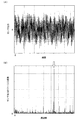
図6に、磁気ヘッド4のシーク動作時およびシーク動作後における回転振動検出器30の出力信号のグラフを示す。図6中の矢印は、シーク動作の終了時点を表す。図6によると、回転振動検出器30の出力信号には、シーク動作後に何らかの振動成分が減衰せずに残存していることがわかる(図6中において破線に取り囲まれた範囲)。
FIG. 6 shows a graph of the output signal of the
図7(A)に、図6中で破線に取り囲まれた範囲を拡大したグラフを示す。また、図7(B)には、この範囲をフーリエ変換したグラフを示す。図7(B)からわかるように、シーク動作後に残存する振動成分は急峻なピークを有している。 FIG. 7A shows a graph in which the range surrounded by the broken line in FIG. 6 is enlarged. FIG. 7B shows a graph obtained by Fourier transforming this range. As can be seen from FIG. 7B, the vibration component remaining after the seek operation has a steep peak.
このようなシーク動作後に残存する振動成分は、共振外乱成分(回転振動検出器30の構造共振に起因する外乱成分)であることが確認された。すなわち、磁気ヘッド4のシーク動作を行うと、回転振動検出器30の出力信号には、シーク動作後に共振外乱成分が残存することが確認された。
It was confirmed that the vibration component remaining after such a seek operation is a resonance disturbance component (a disturbance component caused by the structural resonance of the rotational vibration detector 30). That is, when the seek operation of the magnetic head 4 is performed, it is confirmed that the resonance disturbance component remains in the output signal of the
このため、S1では、後述するステップにおいて共振外乱成分の周波数を推定するために、磁気ヘッド4のシーク動作を行うことによって、回転振動検出器30の出力信号に共振外乱成分が表れるようにしている。
For this reason, in S1, a resonance disturbance component appears in the output signal of the
次に、図5に示したS2およびS3は、周波数推定ステップである。S2は、上記周波数推定部64の機能に基づく。このS2において、主制御回路10は、磁気ヘッド4のシーク動作後に回転振動検出器30の出力信号に表れる共振外乱成分の周波数を推定する。
Next, S2 and S3 shown in FIG. 5 are frequency estimation steps. S2 is based on the function of the
共振外乱成分の周波数の推定は、例えば特開2003−109335号公報に記載されているような、追従ピークフィルタを用いた周波数推定技術を応用することができる。例えば、主制御回路10は、回転振動検出器30の出力信号の位相と、追従ピークフィルタ(図示せず)の出力信号の位相とを比較し、この比較結果に基づいて、追従ピークフィルタのピーク周波数を更新し、共振外乱成分の周波数に追従させていく。これによって、共振外乱成分の周波数が推定される。
For estimation of the frequency of the resonance disturbance component, for example, a frequency estimation technique using a tracking peak filter as described in JP-A-2003-109335 can be applied. For example, the
具体的には、共振外乱成分の周波数の推定は、以下の数式1ないし5を計算することによって行うことができる。
Specifically, the frequency of the resonance disturbance component can be estimated by calculating the following
![]()
![]()
この数式1は、追従ピークフィルタの分母を表す数式である。なお、追従ピークフィルタの分子は、ピーク周波数と関係がないので、詳しい説明を省略する。
xは、回転振動検出器30の出力信号を表す。詳細には、xは、上記図4において、バンドパスフィルタ62から周波数推定部64へ入力される信号を表す。また、yは、追従ピークフィルタの出力信号を表す。
x represents an output signal of the
Cはフィルタ係数である。本実施形態において、このCは、計算回数nに応じて変更される(後に詳しく述べる)。 C is a filter coefficient. In the present embodiment, this C is changed according to the number of calculations n (detailed later).
Bはフィルタ係数である。このBは、ピーク周波数を含むフィルタ係数であり、下記数式2で表される。追従ピークフィルタにおいては、このピーク周波数が、共振外乱成分を推定するための推定周波数とされる。 B is a filter coefficient. This B is a filter coefficient including a peak frequency, and is expressed by the following formula 2. In the tracking peak filter, this peak frequency is an estimated frequency for estimating the resonance disturbance component.
![]()
![]()
fはピーク周波数(推定周波数)を表す。TSはサンプリング時間を表す。 f represents a peak frequency (estimated frequency). T S represents the sampling time.
![]()
![]()
この数式3は、yの2乗平均を表す数式である。a1は係数である。 Formula 3 is a formula representing the mean square of y. a 1 is a coefficient.

この数式4は、推定周波数fを含むフィルタ係数Bを表す数式である。ここで、数式4の右辺第2項は、下記数式5に表すようにdBとする。また、a2は係数である。 Formula 4 is a formula that represents the filter coefficient B including the estimated frequency f. Here, the second term on the right side of Equation 4 is dB as shown in Equation 5 below. Also, a 2 are coefficients.
なお、本実施形態では、共振外乱成分の周波数を推定する際に、回転振動検出器30の出力信号に含まれる外乱成分のうち、より大きな外乱成分の周波数に追従ピークフィルタの推定周波数fを近づける第1モードと、当該大きな外乱成分の周波数に追従ピークフィルタの推定周波数fを収束させる第2モードと、を計算回数nに応じて切替える。
In this embodiment, when estimating the frequency of the resonance disturbance component, the estimated frequency f of the tracking peak filter is made closer to the frequency of the larger disturbance component among the disturbance components included in the output signal of the
具体的には、計算回数nが所定未満の場合に、第1モードとして、上記数式1に含まれるフィルタ係数Cを1よりもやや小さい値に設定し、計算回数nが所定以上の場合に、第2モードとして、フィルタ係数Cを1に設定する。このフィルタ係数Cは、従来の追従ピークフィルタにおいて1に設定されるフィルタ係数である。
Specifically, when the number of calculations n is less than a predetermined value, as the first mode, the filter coefficient C included in
第2モードのようにフィルタ計数Cを1に設定する場合(従来の追従ピークフィルタと同様)、回転振動検出器30の出力信号に含まれる外乱成分に追従ピークフィルタの推定周波数fを収束させることができる。しかしながら、上記図7(B)に示すように、回転振動検出器30の出力信号に複数の外乱成分が含まれる場合(共振外乱成分に限らない)、追従ピークフィルタの推定周波数fがピーク強度の比較的小さな外乱成分に収束してしまうことがある。これは、追従ピークフィルタのゲインが推定周波数fで無限大となり、追従ピークフィルタの出力が外乱成分のピーク強度に依らず同じになるためである。
When the filter count C is set to 1 as in the second mode (similar to the conventional tracking peak filter), the estimated frequency f of the tracking peak filter is converged to the disturbance component included in the output signal of the
他方、第1モードのようにフィルタ係数Cを1よりも小さい値に設定する場合、回転振動検出器30の出力信号に複数の外乱成分が含まれていても、より大きな外乱成分(例えば共振外乱成分)に追従ピークフィルタの推定周波数fを近づけることができる。これは、追従ピークフィルタのゲインが推定周波数fで有限大となり、追従ピークフィルタの出力が外乱成分のピーク強度に依って異なるためである。但し、フィルタ係数Cが1ではないことから、追従ピークフィルタの推定周波数fは、当該大きな外乱成分に近づくだけで、完全には収束しない。
On the other hand, when the filter coefficient C is set to a value smaller than 1 as in the first mode, even if a plurality of disturbance components are included in the output signal of the
このため、本実施形態では、第1モードにより、回転振動検出器30の出力信号に含まれる外乱成分のうち、より大きな外乱成分に追従ピークフィルタの推定周波数fを近づけ、その後、第2モードにより、当該大きな外乱成分の周波数に追従ピークフィルタの推定周波数fを収束させている。これによれば、回転振動検出器30の出力信号に複数の外乱成分が含まれる場合であっても、追従ピークフィルタの推定周波数fをより大きな外乱成分に収束させることができる。
Therefore, in the present embodiment, in the first mode, the estimated frequency f of the tracking peak filter is brought closer to a larger disturbance component among the disturbance components included in the output signal of the
また、第1モードにおいて、フィルタ係数Cは、計算回数nの増加に応じて1に近づくように設定されてもよい。これによれば、第2モードに切り替る前に、追従ピークフィルタの推定周波数fを大きな外乱成分により近づけることができるので、第2モードに切り替えた後に、追従ピークフィルタの推定周波数fが当該大きな外乱成分に収束する精度を高めることができる。 In the first mode, the filter coefficient C may be set to approach 1 as the number of calculations n increases. According to this, since the estimated frequency f of the tracking peak filter can be made closer to a large disturbance component before switching to the second mode, the estimated frequency f of the tracking peak filter is increased after the switching to the second mode. The accuracy of convergence to a disturbance component can be increased.
次に、S3は、上記収束判定部66の機能に基づく。このS3において、主制御回路10は、上記数式5で表されるdBに基づいて、回転振動検出器30の出力信号に含まれる共振外乱成分に追従ピークフィルタの推定周波数fが収束したか否かを判断する。具体的には、主制御回路10は、追従ピークフィルタの計算回数nが既定回数を超えた際のdBの絶対値と閾値とを比較して、推定周波数fが収束したか否かを判断する。
Next, S3 is based on the function of the
ここで、回転振動検出器30の出力信号に含まれる共振外乱成分に追従ピークフィルタの推定周波数fが収束していない場合(S3:NO)、主制御回路10は、S1に戻り、磁気ヘッド4のシーク動作を再び実行するとともに、S2において、それまでの推定周波数fを初期値として、共振外乱成分の周波数を再び推定する。このように、1回のシーク動作で共振外乱成分の周波数を推定しきれない場合であっても、S1およびS2を繰り返して共振外乱成分の周波数を推定する。
Here, when the estimated frequency f of the tracking peak filter has not converged on the resonance disturbance component included in the output signal of the rotational vibration detector 30 (S3: NO), the
次に、S4およびS5は、抑制器設定ステップである。S4において、主制御回路10は、上記S1ないしS3において得られた推定周波数fに基づいて、ノッチフィルタ53の伝達関数に含まれるフィルタ係数(パラメータ)を算出する。また、S5において、主制御回路10は、算出したフィルタ係数をノッチフィルタ53に設定する。
Next, S4 and S5 are suppressor setting steps. In S4, the
具体的には、ノッチフィルタ53の伝達関数は、下記数式6によって表される。
Specifically, the transfer function of the
Xは、ノッチフィルタ53の入力信号、すなわち回転振動検出器30の出力信号を表す。また、Yは、ノッチフィルタ53の出力信号を表す。
X represents an input signal of the
Cは、上記数式1に含まれるフィルタ係数Cと同じフィルタ係数である。ここでは、フィルタ係数Cは1に設定される。
C is the same filter coefficient as the filter coefficient C included in
Bは、上記数式2で表されるフィルタ係数Bと同じフィルタ係数であり、ノッチフィルタ53における特定周波数帯域(抑制が有効となる周波数帯域)の中心周波数(ピーク周波数)に寄与する。
B is the same filter coefficient as the filter coefficient B expressed by Equation 2 above, and contributes to the center frequency (peak frequency) of the specific frequency band (frequency band where suppression is effective) in the
K,E,Fはフィルタ係数であり、ノッチフィルタ53の特定周波数帯域の幅などの特性に寄与する。
K, E, and F are filter coefficients, which contribute to characteristics such as the width of the specific frequency band of the
主制御回路10は、上記S1ないしS3において得られたフィルタ係数B(すなわち、回転振動検出器30の出力信号に含まれる共振外乱成分に収束した追従ピークフィルタの推定周波数fを含むフィルタ係数B)を、数式6で表されるノッチフィルタ53のフィルタ係数Bとして適用する。これにより、ノッチフィルタ53の特定周波数帯域の中心周波数を、回転振動検出器30の出力信号に含まれる共振外乱成分の周波数に合わせることができるので、共振外乱成分を抑制することができる。
The
また、主制御回路10は、上記S1ないしS3において得られたフィルタ係数Bを基に、予め定められた対応関係に応じて他のフィルタ係数K,E,Fを求める。
The
以下、フィルタ係数の対応関係について説明する。フィルタ係数Bと各フィルタ係数K,E,Fとの対応関係は、例えば外部のコンピュータ等で計算されることによって、予め定められる。 Hereinafter, the correspondence between the filter coefficients will be described. The correspondence relationship between the filter coefficient B and each filter coefficient K, E, F is determined in advance, for example, by being calculated by an external computer or the like.
具体的には、外部のコンピュータ等で、所望の特性を有するノッチフィルタを中心周波数を変えて複数作成し、これらのノッチフィルタから、中心周波数に依存するフィルタ係数Bと、他のフィルタ係数K,E,Fとの対応関係を導き出す。 More specifically, an external computer or the like creates a plurality of notch filters having desired characteristics while changing the center frequency, and from these notch filters, a filter coefficient B depending on the center frequency and other filter coefficients K, The correspondence with E and F is derived.
図8に、フィルタ係数の対応関係を導出するための説明図を示す。 FIG. 8 is an explanatory diagram for deriving the correspondence relationship between the filter coefficients.
図8(A)は、外部のコンピュータ等で作成される、互いに異なる中心周波数を有する複数のノッチフィルタの特性を表すグラフである。上段は利得−周波数特性を表し、下段は入出力信号の位相差−周波数特性を表す。 FIG. 8A is a graph showing characteristics of a plurality of notch filters created by an external computer or the like and having different center frequencies. The upper part represents the gain-frequency characteristic, and the lower part represents the phase difference-frequency characteristic of the input / output signal.
これらのノッチフィルタは、回転振動を補償するフィードフォワード制御系で使われることから,低周波数域での位相差−周波数特性が同じになるように作成される。これにより,選ばれるノッチフィルタに依らずに,回転振動が補償される低周波数域でのフィードフォワード制御系の特性が同一になる。 Since these notch filters are used in a feedforward control system that compensates for rotational vibration, they are created so that the phase difference-frequency characteristics in the low frequency range are the same. As a result, the characteristics of the feedforward control system in the low frequency range in which the rotational vibration is compensated are the same regardless of the notch filter selected.
図8(B)は、図8(A)に示した複数のノッチフィルタの、中心周波数に依存するフィルタ係数Bと、他のフィルタ係数K,E,Fとの対応関係を示すグラフである。 FIG. 8B is a graph showing a correspondence relationship between the filter coefficient B depending on the center frequency and the other filter coefficients K, E, and F of the plurality of notch filters shown in FIG.
この図8(B)には、図8(A)に示した複数のノッチフィルタの、中心周波数に依存するフィルタ係数Bと、他のフィルタ係数K,E,Fとの対応関係をプロットした点と、これらプロットした点に対してフィッティングした関数の曲線とを示している。 In FIG. 8B, the correspondence between the filter coefficient B depending on the center frequency and the other filter coefficients K, E, and F of the plurality of notch filters shown in FIG. 8A is plotted. And a curve of a function fitted to these plotted points.
本実施形態では、このようにして得られるフィルタ係数の対応関係を表す関数を、主制御回路10に含まれるメモリ等に予め格納する。なお、関数に限らず、フィルタ係数の対応関係を表すテーブルなどであってもよい。
In the present embodiment, a function representing the correspondence relationship of the filter coefficients obtained in this way is stored in advance in a memory or the like included in the
主制御回路10は、この格納されている関数に基づいて、上記S1ないしS3において得られたフィルタ係数Bから、対応するフィルタ係数K,E,Fを求めるとともに、これらのフィルタ関数をノッチフィルタ53に設定する。
The
これにより、主制御回路10は、特定周波数帯域の幅が比較的狭く、入出力信号の位相差が低減された特性を有するノッチフィルタ53を設定することができる。
Thereby, the
また、予め定められたフィルタ係数の対応関係に基づいてフィルタ係数K,E,Fを求めることで、上記図8に示したような計算を主制御回路10に行わせる必要がなく、ノッチフィルタ53の設定を簡便に行うことができる。
Further, by obtaining the filter coefficients K, E, and F based on the correspondence relationship of the predetermined filter coefficients, it is not necessary to cause the
次に、図5に示したS6は、確認ステップである。この確認ステップにおいて、主制御回路10は、フィルタ係数を設定したノッチフィルタ53が、回転振動検出器30の出力信号に含まれる共振外乱成分を抑制できているか否かを確認する。
Next, S6 shown in FIG. 5 is a confirmation step. In this confirmation step, the
図9に、確認ステップの動作例を示す。なお、以下の説明において、上述のフローチャートと重複するステップについては、図面に同番号を付すことで詳細な説明を省略する。 FIG. 9 shows an operation example of the confirmation step. In the following description, the same steps as those in the above flowchart are denoted by the same reference numerals in the drawings, and detailed description thereof is omitted.
まず、主制御回路10は、ヘッド移動ステップ(S1)により磁気ヘッド4のシーク動作を行うことによって、回転振動検出器30の出力信号に共振外乱成分が表れるようにする。
First, the
次に、主制御回路10は、ノッチフィルタ53の入出力信号に基づいて、回転振動検出器30の出力信号に含まれる共振外乱成分を抑制できているか否かを確認する(S62)。この確認は、ノッチフィルタ53の入力信号の2乗和および出力信号の2乗和を計算することによって行う。
Next, the
ノッチフィルタ53の入力信号の2乗和Pin、出力信号の2乗和Poutは、下記数式7、数式8のように表される。
The square sum P in of the input signal and the square sum P out of the output signal of the
![]()
![]()
![]()
![]()
主制御回路10は、入力信号の2乗和Pinおよび出力信号の2乗和Poutを計算回数Nが所定回数に達するまで計算し、これらの比と閾値を比較することで、共振外乱成分を抑制できているか否かを確認する。
The
このような確認により、2乗和の比が閾値を下回り、共振外乱成分を抑制できていると確認された場合には(S63:YES)、処理を終了する。 If it is confirmed that the ratio of the sum of squares is less than the threshold value and the resonance disturbance component can be suppressed by such confirmation (S63: YES), the process ends.
他方、2乗和の比が閾値を上回り、共振外乱成分を抑制できていない場合には(S63:NO)、図10に示す動作例に移る。この図10に示す動作例は、ノッチフィルタ53の出力信号に残存している共振外乱成分を抑制するための新たなノッチフィルタ(図示せず)を設定する動作である。
On the other hand, when the ratio of the sum of squares exceeds the threshold value and the resonance disturbance component cannot be suppressed (S63: NO), the operation proceeds to the operation example shown in FIG. The operation example shown in FIG. 10 is an operation of setting a new notch filter (not shown) for suppressing the resonance disturbance component remaining in the output signal of the
まず、主制御回路10は、ヘッド移動ステップ(S1)により、磁気ヘッド4のシーク動作を行うことによって、上記S5で設定したノッチフィルタ53(第1ノッチフィルタ)の出力信号に共振外乱成分が表れるようにする。
First, the
次に、主制御回路10は、上記S2と同様の処理により、磁気ヘッド4のシーク動作後にノッチフィルタ53の出力信号に含まれる共振外乱成分の周波数を推定する(S22)。そして、主制御回路10は、得られた推定周波数fに基づいてフィルタ係数を算出して(S4)、上記S5と同様の処理により、算出したフィルタ係数を新たなノッチフィルタ(第2ノッチフィルタ)に設定する(S52)。
Next, the
このように設定された新たなノッチフィルタは、ノッチフィルタ53の下流側(上記図2においてノッチフィルタ53と回転振動補償器55の間)に設けられ、ノッチフィルタ53の出力信号に残存する共振外乱成分を抑制する。
The new notch filter set in this way is provided on the downstream side of the notch filter 53 (between the
次に、主制御回路10は、確認ステップ(S6)を行い、フィルタ係数が設定された新たなノッチフィルタの出力信号に含まれる共振外乱成分が抑制されているか否かを確認し、共振外乱成分が抑制されている場合には(S63:YES)、処理を終了する。他方、新たなノッチフィルタの出力信号に共振外乱成分が残存している場合には(S63:NO)、これまでの処理と同様の処理を、全ての共振外乱成分が抑制されるまで繰り返す。
Next, the
以上の処理によって、回転振動検出器30の出力信号に複数の共振外乱成分が含まれる場合であっても、全ての共振外乱成分を抑制することができる。
With the above processing, even if a plurality of resonance disturbance components are included in the output signal of the
1 磁気ディスク装置、2 磁気ディスク、3 スピンドルモータ、4 磁気ヘッド、5 サスペンションアーム、6 キャリッジ、7 ボイスコイルモータ、9 筐体、10 主制御回路、13 R/Wチャネル、14 ヘッドアンプ、17 モータドライバ、21 トラック、23 サーボデータ領域、25 ユーザデータ領域、30 回転振動検出器、32 加速度センサ、34 回路部、41 誤差信号生成器、45 コントローラ、49 加算器、51 アナログ−デジタル変換器、53 ノッチフィルタ、55 回転振動補償器、60 周波数推定ブロック、62 バンドパスフィルタ、64 周波数推定部、66 収束判定部。
DESCRIPTION OF
Claims (13)
磁気ヘッドと、
前記磁気ヘッドを前記磁気ディスク上に支持し、該磁気ディスクの外側に定められた旋回軸を中心に旋回可能な支持機構と、
前記支持機構を旋回駆動して、前記磁気ヘッドを前記磁気ディスクの略半径方向に移動させるヘッド用アクチュエータと、
装置筐体の前記旋回軸周りの回転振動を検出する回転振動検出器と、
を備え、前記回転振動検出器の出力信号を前記ヘッド用アクチュエータの制御に供する磁気ディスク装置を対象とし、
前記ヘッド用アクチュエータを駆動して、前記磁気ヘッドを前記磁気ディスク上で移動させるヘッド移動ステップと、
前記磁気ヘッドの移動後における前記回転振動検出器の出力信号に含まれる前記回転振動検出器による外乱成分の周波数を推定する周波数推定ステップと、
前記推定した周波数の収束を判定する収束判定ステップと、
前記推定した周波数に基づいて、前記外乱成分を抑制する外乱抑制器を設定する抑制器設定ステップと、
を含むことを特徴とする磁気ディスク装置の制御方法。 A magnetic disk;
A magnetic head;
A support mechanism for supporting the magnetic head on the magnetic disk and capable of turning about a turning axis defined outside the magnetic disk;
A head actuator that pivotally drives the support mechanism to move the magnetic head in a substantially radial direction of the magnetic disk;
A rotational vibration detector for detecting rotational vibration around the pivot axis of the device housing;
A magnetic disk device for providing an output signal of the rotational vibration detector to control of the head actuator,
A head moving step of driving the head actuator to move the magnetic head on the magnetic disk;
A frequency estimating step for estimating a frequency of a disturbance component by the rotational vibration detector included in an output signal of the rotational vibration detector after the movement of the magnetic head;
A convergence determination step for determining convergence of the estimated frequency;
A suppressor setting step for setting a disturbance suppressor for suppressing the disturbance component based on the estimated frequency;
A control method for a magnetic disk device, comprising:
前記外乱抑制器は、デジタルフィルタで構成され、
前記抑制器設定ステップは、前記デジタルフィルタの伝達関数に含まれるパラメータを、前記推定した周波数に応じて設定する、
ことを特徴とする磁気ディスク装置の制御方法。 A method for controlling a magnetic disk device according to claim 1, comprising:
The disturbance suppressor is composed of a digital filter,
The suppressor setting step sets a parameter included in the transfer function of the digital filter according to the estimated frequency.
A method of controlling a magnetic disk device.
前記パラメータは、各周波数において、前記デジタルフィルタが該周波数を含む所定の周波数帯域の信号成分を抑制するように定められる、
ことを特徴とする磁気ディスク装置の制御方法。 A method of controlling a magnetic disk device according to claim 2,
The parameter is determined so that, at each frequency, the digital filter suppresses a signal component of a predetermined frequency band including the frequency.
A method of controlling a magnetic disk device.
前記周波数推定ステップは、
前記回転振動検出器の出力信号に含まれる前記外乱成分のうち、より大きな外乱成分の周波数に推定値を近づけるモードと、
当該大きな外乱成分の周波数に前記推定値を合わせるモードと、
を切替える、ことを特徴とする磁気ディスク装置の制御方法。 A method for controlling a magnetic disk device according to claim 1, comprising:
The frequency estimation step includes:
Of the disturbance components included in the output signal of the rotational vibration detector, a mode for bringing the estimated value closer to the frequency of the larger disturbance component;
A mode for matching the estimated value to the frequency of the large disturbance component;
A method of controlling a magnetic disk device, characterized by:
前記周波数推定ステップにおいて前記外乱成分の周波数が推定されるまで、前記ヘッド移動ステップを繰り返す、
ことを特徴とする磁気ディスク装置の制御方法。 A method for controlling a magnetic disk device according to claim 1, comprising:
Repeating the head moving step until the frequency of the disturbance component is estimated in the frequency estimating step,
A method of controlling a magnetic disk device.
前記回転振動検出器の出力信号が周波数の異なる複数の外乱成分を含む場合に、
前記回転振動検出器の出力信号を対象として、前記ヘッド移動ステップ、前記周波数推定ステップおよび前記抑制器設定ステップを実行し、第1の外乱成分が抑制されるように第1の外乱抑制器を設定した後、
当該第1の外乱抑制器の出力信号を対象として、前記ヘッド移動ステップ、前記周波数推定ステップおよび前記抑制器設定ステップを実行し、第2の外乱成分が抑制されるように第2の外乱抑制器を設定する、
ことを特徴とする磁気ディスク装置の制御方法。 A method for controlling a magnetic disk device according to claim 1, comprising:
When the output signal of the rotational vibration detector includes a plurality of disturbance components having different frequencies,
The first disturbance suppressor is set so that the first disturbance component is suppressed by executing the head moving step, the frequency estimating step, and the suppressor setting step for the output signal of the rotational vibration detector. After
For the output signal of the first disturbance suppressor, the head movement step, the frequency estimation step, and the suppressor setting step are executed, and the second disturbance suppressor is suppressed so that the second disturbance component is suppressed. Set
A method of controlling a magnetic disk device.
前記回転振動検出器は、前記装置筐体、または該装置筐体に取り付けられる基板に設置される、
ことを特徴とする磁気ディスク装置の制御方法。 A method for controlling a magnetic disk device according to claim 1, comprising:
The rotational vibration detector is installed on the device housing or a substrate attached to the device housing.
A method of controlling a magnetic disk device.
磁気ヘッドと、
前記磁気ヘッドを前記磁気ディスク上に支持し、該磁気ディスクの外側に定められた旋回軸を中心に旋回可能な支持機構と、
前記支持機構を旋回駆動して、前記磁気ヘッドを前記磁気ディスクの略半径方向に移動させるヘッド用アクチュエータと、
装置筐体の前記旋回軸周りの回転振動を検出する回転振動検出器と、
前記ヘッド用アクチュエータを駆動して、前記磁気ヘッドを前記磁気ディスク上で移動させるヘッド移動手段と、
前記磁気ヘッドの移動後における前記回転振動検出器の出力信号に含まれる前記回転振動検出器による外乱成分の周波数を推定する周波数推定手段と、
前記推定した周波数の収束を判定する収束判定手段と、
前記推定した周波数に基づいて、前記外乱成分を抑制する外乱抑制器を設定する抑制器設定手段と、
を備え、前記外乱抑制器の出力信号を前記ヘッド用アクチュエータの制御に供する磁気ディスク装置。 A magnetic disk;
A magnetic head;
A support mechanism for supporting the magnetic head on the magnetic disk and capable of turning about a turning axis defined outside the magnetic disk;
A head actuator that pivotally drives the support mechanism to move the magnetic head in a substantially radial direction of the magnetic disk;
A rotational vibration detector for detecting rotational vibration around the pivot axis of the device housing;
Head moving means for driving the head actuator to move the magnetic head on the magnetic disk;
A frequency estimation means for estimating a frequency of a disturbance component by the rotational vibration detector included in an output signal of the rotational vibration detector after the magnetic head is moved;
Convergence determining means for determining convergence of the estimated frequency;
Suppressor setting means for setting a disturbance suppressor that suppresses the disturbance component based on the estimated frequency;
And a magnetic disk device that uses the output signal of the disturbance suppressor to control the head actuator.
前記外乱抑制器は、デジタルフィルタで構成され、
前記抑制器設定手段は、前記デジタルフィルタの伝達関数に含まれるパラメータを、前記推定した周波数に応じて設定する、
ことを特徴とする磁気ディスク装置。 The magnetic disk device according to claim 8,
The disturbance suppressor is composed of a digital filter,
The suppressor setting means sets a parameter included in a transfer function of the digital filter according to the estimated frequency.
A magnetic disk device characterized by the above.
前記パラメータは、各周波数において、前記デジタルフィルタが該周波数を含む所定の周波数帯域の信号成分を抑制するように定められる、
ことを特徴とする磁気ディスク装置。 The magnetic disk device according to claim 9, wherein
The parameter is determined so that, at each frequency, the digital filter suppresses a signal component of a predetermined frequency band including the frequency.
A magnetic disk device characterized by the above.
前記周波数推定手段は、
前記回転振動検出器の出力信号に含まれる前記外乱成分のうち、より大きな外乱成分の周波数に推定値を近づけるモードと、
当該大きな外乱成分の周波数に前記推定値を合わせるモードと、
を切替える、ことを特徴とする磁気ディスク装置。 The magnetic disk device according to claim 8,
The frequency estimation means includes
Of the disturbance components included in the output signal of the rotational vibration detector, a mode for bringing the estimated value closer to the frequency of the larger disturbance component;
A mode for matching the estimated value to the frequency of the large disturbance component;
A magnetic disk device characterized by switching between.
前記外乱成分の周波数が推定されるまで、前記ヘッドの移動が繰り返される、
ことを特徴とする磁気ディスク装置。 The magnetic disk device according to claim 8,
The movement of the head is repeated until the frequency of the disturbance component is estimated.
A magnetic disk device characterized by the above.
前記回転振動検出器は、前記装置筐体、または該装置筐体に取り付けられる基板に設置される、
ことを特徴とする磁気ディスク装置。 The magnetic disk device according to claim 8,
The rotational vibration detector is installed on the device housing or a substrate attached to the device housing.
A magnetic disk device characterized by the above.
Priority Applications (3)
| Application Number | Priority Date | Filing Date | Title |
|---|---|---|---|
| JP2007132834A JP5039943B2 (en) | 2007-05-18 | 2007-05-18 | Magnetic disk drive and control method thereof |
| CNA2008100915927A CN101308665A (en) | 2007-05-18 | 2008-04-21 | Magnetic disk drive and method of controlling the same |
| US12/152,756 US7706099B2 (en) | 2007-05-18 | 2008-05-16 | Magnetic disk drive and method of controlling the same |
Applications Claiming Priority (1)
| Application Number | Priority Date | Filing Date | Title |
|---|---|---|---|
| JP2007132834A JP5039943B2 (en) | 2007-05-18 | 2007-05-18 | Magnetic disk drive and control method thereof |
Publications (3)
| Publication Number | Publication Date |
|---|---|
| JP2008287815A JP2008287815A (en) | 2008-11-27 |
| JP2008287815A5 JP2008287815A5 (en) | 2010-05-13 |
| JP5039943B2 true JP5039943B2 (en) | 2012-10-03 |
Family
ID=40027225
Family Applications (1)
| Application Number | Title | Priority Date | Filing Date |
|---|---|---|---|
| JP2007132834A Expired - Fee Related JP5039943B2 (en) | 2007-05-18 | 2007-05-18 | Magnetic disk drive and control method thereof |
Country Status (3)
| Country | Link |
|---|---|
| US (1) | US7706099B2 (en) |
| JP (1) | JP5039943B2 (en) |
| CN (1) | CN101308665A (en) |
Families Citing this family (15)
| Publication number | Priority date | Publication date | Assignee | Title |
|---|---|---|---|---|
| CN1241833C (en) * | 2000-10-20 | 2006-02-15 | 昭和电工株式会社 | Method of producing low soda alumina, low soda alumina produced by the method and method of producing porcelain |
| KR20090085279A (en) * | 2008-02-04 | 2009-08-07 | 삼성전자주식회사 | Apparatus for hard disk drive and method for design an additional controller in hard disc drive |
| US7852588B1 (en) * | 2008-06-23 | 2010-12-14 | Western Digital Technologies, Inc. | Disk drive adjusting gain of shock detector relative to resonant frequency amplitude |
| US8050160B2 (en) * | 2008-08-29 | 2011-11-01 | Kabushiki Kaisha Toshiba | Characterizing frequency response of a multirate system |
| JP5308799B2 (en) * | 2008-12-04 | 2013-10-09 | エイチジーエスティーネザーランドビーブイ | Disk drive and servo control method for the head |
| JP2010146614A (en) * | 2008-12-16 | 2010-07-01 | Hitachi Global Storage Technologies Netherlands Bv | Disk drive and control method thereof |
| JP2011060347A (en) | 2009-09-07 | 2011-03-24 | Hitachi Global Storage Technologies Netherlands Bv | Disk drive |
| US8213105B2 (en) * | 2009-11-05 | 2012-07-03 | International Business Machines Corporation | Cancellation of time-varying periodic disturbances in servo control systems |
| CN102087855B (en) * | 2009-12-08 | 2015-04-22 | 淮南东正电子科技有限公司 | Rotating vibration test system and method of storage equipment |
| US8634159B2 (en) * | 2012-03-22 | 2014-01-21 | HGST Netherlands B.V. | Magnetic recording disk drive with three sensors for rotational and linear vibration compensation |
| US9214185B1 (en) * | 2014-06-29 | 2015-12-15 | Avago Technologies General Ip (Singapore) Pte. Ltd. | Adaptive filter-based narrowband interference detection, estimation and cancellation |
| TW201617753A (en) * | 2014-11-12 | 2016-05-16 | Nat Univ Chung Cheng | Adaptive recessed filter vibration reducing control device |
| CN104636225A (en) * | 2015-03-05 | 2015-05-20 | 浪潮电子信息产业股份有限公司 | Method for assessment of influences of server vibration on performances of magnetic disk |
| US10629234B1 (en) * | 2019-06-27 | 2020-04-21 | Western Digital Technologies, Inc. | Data storage device computing notch filters for multiple temperatures |
| CN111863037B (en) * | 2020-07-28 | 2021-08-10 | 洛阳师范学院 | Computer cavity device for avoiding impact sound caused by abnormality during displacement |
Family Cites Families (9)
| Publication number | Priority date | Publication date | Assignee | Title |
|---|---|---|---|---|
| JPH10199168A (en) | 1997-01-10 | 1998-07-31 | Hitachi Ltd | Disk storage device |
| JP2001014782A (en) | 1999-06-30 | 2001-01-19 | Hitachi Ltd | Magnetic disk device |
| US6496320B1 (en) * | 2000-02-09 | 2002-12-17 | Seagate Technology Llc | Adaptive attenuation of multi-axis vibrational disturbance |
| JP4494665B2 (en) * | 2001-03-28 | 2010-06-30 | 富士通株式会社 | MOVING BODY POSITION CONTROL DEVICE, MOVING BODY POSITION CONTROL DEVICE BAND-STOPPING FILTER ADJUSTMENT PROGRAM, AND MOVING BODY POSITION CONTROL DEVICE LOOP GAIN ADJUSTMENT PROGRAM |
| JP3870053B2 (en) | 2001-09-21 | 2007-01-17 | ヒタチグローバルストレージテクノロジーズネザーランドビーブイ | Data storage device, positioning device and positioning method |
| US7268968B2 (en) * | 2004-09-30 | 2007-09-11 | Hitachi Global Storage Technologies Netherlands B.V. | Vibration suppression for servo control |
| JP2007095119A (en) * | 2005-09-27 | 2007-04-12 | Hitachi Global Storage Technologies Netherlands Bv | Disk device and control method of same |
| US7345841B2 (en) * | 2006-02-07 | 2008-03-18 | Hitachi Global Storage Technologies Netherlands B.V. | Disk drive using a disturbance sensor for disturbance frequency-identification and suppression |
| US7145746B1 (en) * | 2006-04-14 | 2006-12-05 | Hitachi Global Storage Technologies Netherlands B.V. | Disk drive with adaptive control of periodic disturbances |
-
2007
- 2007-05-18 JP JP2007132834A patent/JP5039943B2/en not_active Expired - Fee Related
-
2008
- 2008-04-21 CN CNA2008100915927A patent/CN101308665A/en active Pending
- 2008-05-16 US US12/152,756 patent/US7706099B2/en not_active Expired - Fee Related
Also Published As
| Publication number | Publication date |
|---|---|
| US7706099B2 (en) | 2010-04-27 |
| CN101308665A (en) | 2008-11-19 |
| JP2008287815A (en) | 2008-11-27 |
| US20080285170A1 (en) | 2008-11-20 |
Similar Documents
| Publication | Publication Date | Title |
|---|---|---|
| JP5039943B2 (en) | Magnetic disk drive and control method thereof | |
| JP5112786B2 (en) | Adaptive disturbance suppression method, computer-readable recording medium, adaptive disturbance suppression device, disk drive device, and disk drive device control method | |
| US7869157B2 (en) | Magnetic disk drive having dual actuator | |
| JP4783248B2 (en) | POSITION CONTROL METHOD, POSITION CONTROL DEVICE, AND MEDIUM STORAGE DEVICE WITH DISTURBANCE SUPPRESSING FUNCTION | |
| US7466101B2 (en) | Head position control method, head position control device, and disk device | |
| US7583465B2 (en) | Disk drive adaptive resonance compensation method and apparatus | |
| JP4769141B2 (en) | Head position control method, head position control device, and disk device | |
| EP1881492A2 (en) | Device and method for adjusting distance between magnetic head and data storage medium | |
| KR100585166B1 (en) | Apparatus and method for controlling compensation of non-repeatable run out and disk drive using the same | |
| JP2010073284A (en) | Servo control system of head and servo control method of head | |
| JP2008171531A (en) | Data recorder | |
| JP4189119B2 (en) | Head positioning control system and magnetic disk apparatus equipped with the system | |
| US7538964B2 (en) | Magnetic disk drive | |
| JPH1139814A (en) | Magnetic disk apparatus | |
| JP4109812B2 (en) | Positioning control device | |
| JP3779668B2 (en) | Disk storage device and head positioning control method | |
| JP4283979B2 (en) | Positioning control device | |
| JP2008052794A (en) | Magnetic disk unit | |
| JP4595038B2 (en) | Disk device, head position control device, and head position control method | |
| CN116844578A (en) | disk device | |
| JP2004303307A (en) | Magnetic disk drive |
Legal Events
| Date | Code | Title | Description |
|---|---|---|---|
| A521 | Request for written amendment filed |
Free format text: JAPANESE INTERMEDIATE CODE: A523 Effective date: 20100329 |
|
| A621 | Written request for application examination |
Free format text: JAPANESE INTERMEDIATE CODE: A621 Effective date: 20100329 |
|
| A977 | Report on retrieval |
Free format text: JAPANESE INTERMEDIATE CODE: A971007 Effective date: 20111024 |
|
| A131 | Notification of reasons for refusal |
Free format text: JAPANESE INTERMEDIATE CODE: A131 Effective date: 20111101 |
|
| A521 | Request for written amendment filed |
Free format text: JAPANESE INTERMEDIATE CODE: A523 Effective date: 20120131 |
|
| TRDD | Decision of grant or rejection written | ||
| A01 | Written decision to grant a patent or to grant a registration (utility model) |
Free format text: JAPANESE INTERMEDIATE CODE: A01 Effective date: 20120508 |
|
| A01 | Written decision to grant a patent or to grant a registration (utility model) |
Free format text: JAPANESE INTERMEDIATE CODE: A01 |
|
| A61 | First payment of annual fees (during grant procedure) |
Free format text: JAPANESE INTERMEDIATE CODE: A61 Effective date: 20120605 |
|
| R150 | Certificate of patent or registration of utility model |
Free format text: JAPANESE INTERMEDIATE CODE: R150 |
|
| FPAY | Renewal fee payment (event date is renewal date of database) |
Free format text: PAYMENT UNTIL: 20150720 Year of fee payment: 3 |
|
| R250 | Receipt of annual fees |
Free format text: JAPANESE INTERMEDIATE CODE: R250 |
|
| R250 | Receipt of annual fees |
Free format text: JAPANESE INTERMEDIATE CODE: R250 |
|
| LAPS | Cancellation because of no payment of annual fees |