JP5035895B2 - Power generation control device - Google Patents
Power generation control device Download PDFInfo
- Publication number
- JP5035895B2 JP5035895B2 JP2007252429A JP2007252429A JP5035895B2 JP 5035895 B2 JP5035895 B2 JP 5035895B2 JP 2007252429 A JP2007252429 A JP 2007252429A JP 2007252429 A JP2007252429 A JP 2007252429A JP 5035895 B2 JP5035895 B2 JP 5035895B2
- Authority
- JP
- Japan
- Prior art keywords
- cylinder
- engine
- stroke
- power generation
- speed
- Prior art date
- Legal status (The legal status is an assumption and is not a legal conclusion. Google has not performed a legal analysis and makes no representation as to the accuracy of the status listed.)
- Expired - Fee Related
Links
Images


Classifications
-
- H—ELECTRICITY
- H02—GENERATION; CONVERSION OR DISTRIBUTION OF ELECTRIC POWER
- H02P—CONTROL OR REGULATION OF ELECTRIC MOTORS, ELECTRIC GENERATORS OR DYNAMO-ELECTRIC CONVERTERS; CONTROLLING TRANSFORMERS, REACTORS OR CHOKE COILS
- H02P9/00—Arrangements for controlling electric generators for the purpose of obtaining a desired output
-
- H—ELECTRICITY
- H02—GENERATION; CONVERSION OR DISTRIBUTION OF ELECTRIC POWER
- H02P—CONTROL OR REGULATION OF ELECTRIC MOTORS, ELECTRIC GENERATORS OR DYNAMO-ELECTRIC CONVERTERS; CONTROLLING TRANSFORMERS, REACTORS OR CHOKE COILS
- H02P6/00—Arrangements for controlling synchronous motors or other dynamo-electric motors using electronic commutation dependent on the rotor position; Electronic commutators therefor
- H02P6/14—Electronic commutators
- H02P6/16—Circuit arrangements for detecting position
-
- F—MECHANICAL ENGINEERING; LIGHTING; HEATING; WEAPONS; BLASTING
- F02—COMBUSTION ENGINES; HOT-GAS OR COMBUSTION-PRODUCT ENGINE PLANTS
- F02N—STARTING OF COMBUSTION ENGINES; STARTING AIDS FOR SUCH ENGINES, NOT OTHERWISE PROVIDED FOR
- F02N11/00—Starting of engines by means of electric motors
- F02N11/04—Starting of engines by means of electric motors the motors being associated with current generators
-
- F—MECHANICAL ENGINEERING; LIGHTING; HEATING; WEAPONS; BLASTING
- F02—COMBUSTION ENGINES; HOT-GAS OR COMBUSTION-PRODUCT ENGINE PLANTS
- F02N—STARTING OF COMBUSTION ENGINES; STARTING AIDS FOR SUCH ENGINES, NOT OTHERWISE PROVIDED FOR
- F02N11/00—Starting of engines by means of electric motors
- F02N11/08—Circuits or control means specially adapted for starting of engines
- F02N2011/0881—Components of the circuit not provided for by previous groups
- F02N2011/0896—Inverters for electric machines, e.g. starter-generators
-
- F—MECHANICAL ENGINEERING; LIGHTING; HEATING; WEAPONS; BLASTING
- F02—COMBUSTION ENGINES; HOT-GAS OR COMBUSTION-PRODUCT ENGINE PLANTS
- F02N—STARTING OF COMBUSTION ENGINES; STARTING AIDS FOR SUCH ENGINES, NOT OTHERWISE PROVIDED FOR
- F02N2200/00—Parameters used for control of starting apparatus
- F02N2200/02—Parameters used for control of starting apparatus said parameters being related to the engine
- F02N2200/021—Engine crank angle
-
- F—MECHANICAL ENGINEERING; LIGHTING; HEATING; WEAPONS; BLASTING
- F02—COMBUSTION ENGINES; HOT-GAS OR COMBUSTION-PRODUCT ENGINE PLANTS
- F02P—IGNITION, OTHER THAN COMPRESSION IGNITION, FOR INTERNAL-COMBUSTION ENGINES; TESTING OF IGNITION TIMING IN COMPRESSION-IGNITION ENGINES
- F02P7/00—Arrangements of distributors, circuit-makers or -breakers, e.g. of distributor and circuit-breaker combinations or pick-up devices
- F02P7/06—Arrangements of distributors, circuit-makers or -breakers, e.g. of distributor and circuit-breaker combinations or pick-up devices of circuit-makers or -breakers, or pick-up devices adapted to sense particular points of the timing cycle
- F02P7/067—Electromagnetic pick-up devices, e.g. providing induced current in a coil
Landscapes
- Engineering & Computer Science (AREA)
- Power Engineering (AREA)
- Control Of Vehicle Engines Or Engines For Specific Uses (AREA)
- Secondary Cells (AREA)
- Control Of Eletrric Generators (AREA)
Description
本発明は、発電制御装置に関し、特に、エンジン発電機の出力電流をエンジンのフリクションが小さい予定区間でのみバッテリや負荷に供給するように制御する発電制御装置に関する。 The present invention relates to a power generation control device, and more particularly to a power generation control device that controls an output current of an engine generator to be supplied to a battery or a load only in a scheduled section where engine friction is small.
自動二輪車や四輪自動車等、エンジンで駆動される車両は、エンジンで駆動される発電機を備え、車両での使用電力を供給するバッテリは、この発電機の出力電流で充電される。また、一般に、車載発電機はエンジン始動用モータに兼用される。 A vehicle driven by an engine such as a motorcycle or a four-wheeled vehicle includes a generator driven by the engine, and a battery that supplies electric power used in the vehicle is charged by an output current of the generator. In general, the on-vehicle generator is also used as an engine starting motor.
車載発電機による発電量はエンジンの負荷に応じて可変制御されることが知られている。例えば、特表平3−504407号公報には、バッテリ電圧が所定レベルに達した場合に発電機能を停止させる交流発電機式バッテリ充電方法において、エンジンに大きい負荷が掛かっている場合には、所定レベルにまでバッテリが充電されていなくても交流発電機の発電機能を停止または低減させることにより、エンジンの効率低下の防止を図るバッテリ充電方法が提案されている。 It is known that the amount of power generated by the in-vehicle generator is variably controlled according to the engine load. For example, Japanese Patent Laid-Open No. 3-504407 discloses a method of charging an AC generator battery that stops a power generation function when the battery voltage reaches a predetermined level. There has been proposed a battery charging method for preventing reduction in engine efficiency by stopping or reducing the power generation function of an AC generator even when the battery is not charged to the level.
また、特開平3−212200号公報には、電気負荷状態や、自動車に適用した場合の自動車の運転状態に応じて界磁巻線電流を制御する装置において、ノック発生時に発電機の界磁電流を制御したり、界磁電流を停止したりする制御装置が提案されている。
特許文献1や2に記載された従来の発電制御装置または充電制御装置では、負荷が大きい場合には発電量を制限してエンジンの負荷を軽減できる。一方、4サイクルエンジンでは、各サイクル(行程)によってフリクション(エンジンが作動中に、エンジンの機能上、ピストンが移動する方向と反対方向に作用する力)が異なるので、このフリクションを考慮しないで、単にエンジン全体に掛かる負荷状態のみで発電量を制御したとしても行程間のフリクションの違いによるトルク変動を軽減することが困難である。
In the conventional power generation control device or the charging control device described in
特に、エンジンが低回転数域で運転されている場合は、全体に出力トルクが小さいので、発電量を制限したとしても各行程間のフリクションの違いによるトルク変動でエンジン回転が円滑さを欠く場合がありえる。つまり、一般的な負荷状態のみに依存して発電量を制御してもエンジン回転の円滑さを大きくは改善できない場合がある。 In particular, when the engine is operating in a low speed range, the output torque is small overall, so even if the power generation amount is limited, the engine rotation lacks smoothness due to torque fluctuations due to friction differences between strokes There can be. In other words, even if the power generation amount is controlled depending only on the general load state, the smoothness of the engine rotation may not be greatly improved.
本発明の目的は、各行程のフリクションを考慮して発電量を制御することにより、特に低回転数域でのトルクの平滑化を図ることができる発電制御装置を提供することにある。 An object of the present invention is to provide a power generation control device capable of smoothing torque particularly in a low rotational speed range by controlling the power generation amount in consideration of the friction of each stroke.
前記目的を達成するための本発明は、V型2気筒4サイクルエンジンで駆動される発電機の発電制御装置において、発電機の出力電流を制御するスイッチング回路と、前記スイッチング回路を、一方の気筒の爆発行程を含む区間であって、他方の気筒の圧縮行程と重ならない区間に予め設定した周期充電制御範囲でのみ作動させる周期充電制御手段とを具備した点に第1の特徴がある。 In order to achieve the above object, the present invention provides a generator control device for a generator driven by a V-type two-cylinder four-cycle engine, wherein a switching circuit for controlling the output current of the generator, and the switching circuit are connected to one cylinder There is a first feature in that it includes a period charge control means that operates only within a preset period charge control range in a section including the explosion stroke of the other cylinder and does not overlap with the compression stroke of the other cylinder.
また、本発明は、前記周期充電制御範囲が、エンジンの回転数に応じて、エンジン回転数が低いほど前記一方のエンジンの爆発行程側に移行し、その範囲が短縮されている点に第2の特徴がある。 Further, the second aspect of the present invention is that the period charge control range shifts to the explosion stroke side of the one engine as the engine speed is lower, and the range is shortened according to the engine speed. There are features.
また、本発明は、前記周期充電制御範囲が、予め設定したアイドル回転数とアイドル回転数より高い値に設定された通常充電開始回転数との間でのみ有効とされ、前記通常充電開始回転数以上のエンジン回転数領域では、4サイクルの全てで前記スイッチング回路を作動させ、全サイクルで発電制御を行うように構成されている点に第3の特徴がある。 In the present invention, the periodic charge control range is valid only between a preset idle speed and a normal charge start speed set to a value higher than the idle speed, and the normal charge start speed is set. The engine speed range described above has a third feature in that the switching circuit is operated in all four cycles and power generation control is performed in all cycles.
また、本発明は、前記二つの気筒のそれぞれの爆発行程が、エンジンの1サイクルの中で、一方のエンジンの半サイクル側に偏って設定されている点に第4の特徴がある。 In addition, the present invention has a fourth feature in that the explosion strokes of the two cylinders are set so as to be biased toward the half cycle side of one engine in one cycle of the engine.
第1の特徴を有する本発明によれば、二つの気筒のうち、一方の気筒におけるフリクションの小さい爆発行程を含んでいて、かつ、他方の気筒におけるフリクションの大きい圧縮行程と重ならない区間に予め定めた周期充電制御範囲でのみ発電され、この発電による負荷がエンジン自体のフリクションに加わる。したがって、フリクションが大きい他の行程との間でトルクの均衡化が図られ、吸気効率が安定する。 According to the present invention having the first feature, the two cylinders are preliminarily determined in a section that includes an explosion stroke with a small friction in one cylinder and does not overlap with a compression stroke with a large friction in the other cylinder. Power is generated only in the periodic charge control range, and the load due to this power generation is added to the friction of the engine itself. Therefore, the torque is balanced with the other strokes where the friction is large, and the intake efficiency is stabilized.
第2の特徴を有する本発明によれば、エンジン回転数が低い領域であるほど、周期充電制御範囲が短縮される。特に、エンジン回転数が低い領域では、フリクションがより小さい爆発行程で発電が行われるので、発電負荷の影響を最小化しつつ最低限の発電を行うことができる。また、最低限の発電を行うことにより燃費の向上も図られる。 According to the present invention having the second feature, the period charge control range is shortened as the engine speed is lower. In particular, in a region where the engine speed is low, power generation is performed in an explosion stroke with a smaller friction, so that the minimum power generation can be performed while minimizing the influence of the power generation load. In addition, fuel efficiency can be improved by performing minimum power generation.
第3の特徴を有する本発明によれば、周期充電制御範囲の制限をアイドル回転数から通常充電開始回転数の間、つまり比較的低回転数の領域で行うので、特にトルクの小さい低回転数領域で、全サイクルを通じて発電を行う場合と比べて、発電による負荷の増大を抑制することができるので、低回転数域でのエンジン回転が安定化する。 According to the present invention having the third feature, the periodic charge control range is limited between the idle rotation speed and the normal charge start rotation speed, that is, in a relatively low rotation speed region, so that the low rotation speed with particularly small torque is achieved. Compared with the case where power generation is performed throughout the entire region, an increase in load due to power generation can be suppressed, so that engine rotation in a low engine speed range is stabilized.
第4の特徴を有する本発明によれば、爆発行程が1サイクル中の一方のエンジンの半サイクル側に偏っており、その一方の爆発行程で発電負荷が付加されるので、この爆発行程ではエンジンの回転がよりスムーズになる。これと比べて、他方の爆発行程では発電負荷が付加されないので、エンジン回転速度が比較的大きいまま維持され、低速時のエンジンの鼓動感をある程度維持できる。 According to the present invention having the fourth feature, the explosion stroke is biased toward the half cycle side of one engine in one cycle, and a power generation load is added in the one explosion stroke. The rotation becomes smoother. In contrast, since no power generation load is added in the other explosion stroke, the engine rotation speed is maintained relatively high, and the beating feeling of the engine at a low speed can be maintained to some extent.
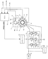
以下、図面を参照して本発明の一実施形態を説明する。図1は、本発明の発電制御装置の一実施形態に係る充電制御装置のシステム構成を示す図である。図1において、発電機1は、エンジン2で駆動されて3相交流を出力する。出力された3相交流は直流に変換されて負荷16およびバッテリ17に供給される。
Hereinafter, an embodiment of the present invention will be described with reference to the drawings. FIG. 1 is a diagram showing a system configuration of a charge control device according to an embodiment of the power generation control device of the present invention. In FIG. 1, a
エンジン2は、例えば、二つの気筒が相対角度52°で配置された、いわゆるV型2気筒の4サイクルエンジンである。但し、二つの気筒の相対角度は52°に限定されず、任意の角度を採用することができる、発電機1は、そのロータマグネットを有するインナロータがエンジン2のクランク軸に連結され、インナロータの外周側に配置されたアウタステータの3相巻線から発電出力を得る形式、つまりインナロータ/アウタステータ形式が好ましいが、この形式に限定されるものではない。
The
エンジン2には、カム角を検出するカム角センサ4とクランク角を検出するクランク角センサ5とが設けられ、発電機1には発電機1の回転角度(以下、「ACG角」という)を検出するACG角センサ6が設けられる。
The
カム角センサ4は、エンジン2のカム軸(図示せず)に連結された回転部材7の周囲に突出して設けられた三つの検出部位8a、8b、8cに対向配置されており、各検出部位8a、8b、8cを検出する毎に変化するカム角信号を出力する。検出部位8aと8cとの相対角度は180°に設定され、検出部位8aと8cとの間に検出部位8bが配置されている。検出部位8bと8cとの間に、二つの気筒のうち、一方の気筒(以下、「第2気筒」という)の排気上死点つまりオーバーラップトップが位置するように検出部位8bと検出部位8cとの位置を設定する。
The
したがって、回転部材7が矢印Aの方向に回転するように設定されている場合、カム角センサ4は、検出部位8a、8b、および8cの順で検出信号を出力する。4サイクルエンジンでは、カム軸に設けられる回転部材7はクランク軸の2回転に対して1回転するように構成されているので、検出部位8aと8bとの相対角度180°はクランク角360°に対応する。
Therefore, when the
クランク角センサ5は、クランク軸に連結された回転部材9の周囲に突出して設けられた検出部位10に対向配置されており、回転部材9が回転して複数の検出部位10を検出する毎に変化するクランク角信号を出力する。検出部位10は30°間隔で配置されているが、1個所だけ検出部位10が形成されていない欠け歯部分が設けられている。したがって、この1個所では検出部位10の間隔が60°と、広くなっており、この欠け歯部分を挟む二つの検出部位10の検出信号の間隔は他より大きくなる。
The
ACG角センサ6は、発電機1のロータ11の周囲に突出して設けられた検出部位12に対向配置されており、検出部位12を検出する毎に変化するACG角信号を出力する。検出部位12は15°間隔で配置されている。
The
なお、カム角センサ4、クランク角センサ5、およびACG角センサ6は、それぞれ突起状の検出部位8a〜8c、10、12の有無に応じて変化する信号を出力するものに限らず、検出部位8a〜8c、10,12と同様の間隔で極性が異なるように配置されたセンサ用マグネットに対応して検出信号を出力するものであってもよい。
The
ACGドライバ13は、発電機1に設けられるスイッチング回路14を制御して発電機1の出力を制御する。スイッチング回路14は、FET71〜76で3相ブリッジ回路を有し、これらFETをスイッチングして発電機1の出力交流を整流するとともに、これらFETの通電位相を変化させるデューティ制御によって出力電圧を制御する。
The
スイッチング回路14で制御された発電機1の出力は負荷16およびバッテリ17に接続される。ACGドライバ13はバッテリ17の残量や負荷状態に応じてFET71〜76のオン時間(デューティ)を決定する。例えば、バッテリ残量が少ない場合、および負荷が大きいときはデューティを増大させるように制御する。
The output of the
ECU15には、カム角信号、クランク角信号、およびACG角信号が入力される。ECU15はカム角信号によって気筒判別を行うとともにクランク角信号とカム角信号とに基づいて行程判別を行う。また、ECU15はクランク角信号によってエンジン回転数Neを検出するとともに、燃料噴射および点火タイミングを決定するためのFI−IGステージ(以下、単に「ステージ」という)を検出する。さらに、ECU15は、ACG角信号によって前記スイッチング回路14のスイッチングタイミングを検出する。
The
さらに、ECU15は、4サイクル中の、予め決定されているフリクションが小さい区間を検出して、この区間でのみ充電を行うための周期充電制御信号をACGドライバ13に出力する。この周期充電は、エンジン回転数Neが、予定のアイドル回転数NeIDL以上であって、かつ通常充電開始回転数NeCH以下の場合に実行される。エンジン回転数Neが通常充電開始回転数NeCH以上である場合は、前記フリクションが小さいとされている区間に限らず、それ以外の区間でも充電を行う。また、エンジン回転数Neが、アイドル回転数NeIDL未満である場合は、充電は行わない。
Further, the
図2は、周期充電制御のタイミングチャートであり、エンジン2の1サイクルつまり4行程分(クランク角720°分)のタイミングを示すものである。上述のように、カム角信号は1サイクルで3回の信号変化をする。つまりカム角センサはクランク軸が2回転する間に3個のパルス信号を発生する。クランク角信号は30°間隔で発生する。上述のように、検出部位間が広くなっている欠け歯部分ではクランク角信号は60°間隔となる。クランク角信号の間隔が広くなる個所が1サイクルに2回現れるが、そのうちの1回が、検出部位8b、8cによる二つのカム角信号の間に位置するように設定する。つまり、この部分に第2気筒のオーバーラップトップつまり排気上死点が位置するようにクランク軸とカム軸との関係を設定しておく。
FIG. 2 is a timing chart of the periodic charging control, and shows the timing of one cycle of the
ACG角信号は検出部位12の配置間隔に対応して15°間隔で発生する。
The ACG angle signal is generated at 15 ° intervals corresponding to the arrangement intervals of the
上記カム角信号、クランク角信号、およびACG角信号に基づくステージの決定方法と、行程および気筒の判別方法とを説明する。まず、クランク角信号を検出する毎に、その検出周期を算出しするように設定しておく。そして、カム角信号が検出された後にクランク角信号が検出されると、その直後にACG角信号が検出されたタイミングを第2気筒オーバーラップトップと仮決定し、所定のステージ番号を割り当てる。その後に検出されるクランク角信号と直前のクランク角信号の周期がクランク角30°に対応する周期であれば、前記仮決定は取り消される。一方、前記仮決定の後に検出されるクランク角信号と直前のクランク角信号の周期がクランク角60°に対応する周期であれば前記仮決定は本決定となる。この第2気筒オーバーラップトップとステージ番号の確定から、クランク軸が360°回転した位置が第2気筒圧縮上死点と決定される。クランク角360°はACG角信号の検出個数によって判定できる。
A stage determination method based on the cam angle signal, crank angle signal, and ACG angle signal, and a stroke and cylinder determination method will be described. First, every time a crank angle signal is detected, the detection cycle is set to be calculated. When the crank angle signal is detected after the cam angle signal is detected, the timing at which the ACG angle signal is detected immediately after that is temporarily determined as the second cylinder overlap top, and a predetermined stage number is assigned. If the cycle of the crank angle signal detected after that and the cycle of the immediately preceding crank angle signal are cycles corresponding to a crank angle of 30 °, the provisional decision is canceled. On the other hand, if the cycle of the crank angle signal detected after the temporary determination and the immediately preceding crank angle signal is a cycle corresponding to a crank angle of 60 °, the temporary determination becomes the final determination. From the determination of the second cylinder overlap top and the stage number, the position where the crankshaft has rotated 360 ° is determined as the second cylinder compression top dead center. The
第2気筒圧縮上死点と第2気筒排気上死点とが決定されれば、予め設定されている第1気筒圧縮上死点および第1気筒排気上死点と第2気筒圧縮上死点および第2気筒排気上死点との相対関係から第1気筒圧縮上死点および第1気筒排気上死点が決定される。 If it is determined by the second on-cylinder compression dead point and the second on the cylinder exhaust dead point, preset first on cylinder compression dead center is and the first cylinder exhaust top dead center and the second air cylinder compression on The first cylinder compression top dead center and the first cylinder exhaust top dead center are determined from the relative relationship between the dead center and the second cylinder exhaust top dead center.
図2の例では、第1気筒圧縮上死点の直前とその前の二つのクランク角信号の間をステージ番号「0」に設定してある。 In the example of FIG. 2, the stage number “0” is set between the two crank angle signals immediately before and before the first cylinder compression top dead center.
上述のように判定した各気筒の圧縮上死点および排気上死点に基づいて、各気筒の吸入行程、圧縮行程、爆発行程、および排気行程が、図2の下から2段目、3段目に示すように決定される。そして、これらの行程のうち、フリクションが小さいタイミングでのみ充電を行うようにACGドライバ13を制御する。つまり、発電負荷が加わっても全体としてエンジンのフリクションが大きくなりすぎないタイミングを選択してスイッチング回路14を作動させ、発電電力を負荷16やバッテリ17に接続する。
Based on the compression top dead center and exhaust top dead center of each cylinder determined as described above, the intake stroke, compression stroke, explosion stroke, and exhaust stroke of each cylinder are in the second and third stages from the bottom in FIG. Determined as shown. Then, the
エンジンは1サイクルのうち爆発行程で最も大きい力を発生するので発電による負荷の影響を受けにくい。次いで、排気行程が発電による負荷の影響を受けにくい。排気行程では爆発行程による慣性を有しているからである。吸入行程では爆発行程の慣性が小さくなっているので、発電による負荷の影響はやや大きい。圧縮行程では、吸排気弁が閉じている上に、爆発行程の慣性は極めて小さくなっているので、発電による負荷がエンジン回転の安定性に最も大きい影響を与える。 Since the engine generates the largest force in the explosion stroke in one cycle, it is not easily affected by the load caused by power generation. Next, the exhaust stroke is not easily affected by the load caused by power generation. This is because the exhaust stroke has inertia due to the explosion stroke. Since the inertia of the explosion stroke is small in the intake stroke, the influence of the load due to power generation is somewhat large. In the compression stroke, since the intake and exhaust valves are closed and the inertia of the explosion stroke is extremely small, the load due to power generation has the greatest influence on the stability of the engine rotation.
したがって、爆発行程を中心とした区間で充電を行うのがよいが、2気筒エンジンにおいては、爆発行程が2個所に現れるので、そのうちの1個所を選択するのがよい。図2に示した例では、第1気筒の爆発行程は第2気筒の吸入および圧縮行程に重なる部分を有している。一方、第2気筒の爆発行程は第1気筒の排気および吸入行程に重なる部分を有している。この関係に鑑みると、第2気筒の圧縮行程を中心に、その前後の一部を含めた区間で充電を行うのが、発電による負荷の影響を考慮した場合望ましい。 Therefore, it is preferable to charge in the section centered on the explosion stroke. However, in a two-cylinder engine, the explosion stroke appears in two places, and it is better to select one of them. In the example shown in FIG. 2, the explosion stroke of the first cylinder has a portion overlapping the suction and compression strokes of the second cylinder. On the other hand, the explosion stroke of the second cylinder has a portion overlapping the exhaust and suction strokes of the first cylinder. In view of this relationship, it is desirable to charge in a section including a part before and after the compression stroke of the second cylinder in consideration of the influence of the load due to power generation.
そこで、第2気筒の爆発行程を中心に、圧縮行程と排気行程の一部分を含めた区間を充電範囲と設定した。この範囲は発電出力によってバッテリ17が充電される観点から「周期充電制御範囲」と呼ぶ。図2の例では、周期充電制御範囲に第2気筒の圧縮行程の後半部分を含めているが、この圧縮行程の後半部分は第1気筒の排気行程前半に重なっているので、第2気筒の圧縮行程の大きいフリクションは第1気筒の排気行程の小さいフリクションで相殺され、比較的フリクションは小さい区間である。また、第2気筒の排気行程まで周期充電制御範囲に含めているが、この排気行程は第1気筒の吸入行程と重なっていてフリクションは小さい区間である。
Therefore, a range including a part of the compression stroke and the exhaust stroke centering on the explosion stroke of the second cylinder is set as the charging range. This range is called a “periodic charge control range” from the viewpoint of charging the
このように設定した周期充電制御範囲では、第1気筒の爆発行程では発電による負荷は加わらずに、第2気筒の爆発行程でのみ発電による負荷が加わるので、第2気筒に比べて第1気筒の爆発が強調され、エンジンの鼓動感を増幅するという効果も生じる。 In the periodic charge control range set in this way, the load due to power generation is not applied during the explosion stroke of the first cylinder, but the load due to power generation is applied only during the explosion stroke of the second cylinder. Therefore, the first cylinder is compared with the second cylinder. The explosion of the engine is emphasized and the effect of amplifying the feeling of beating of the engine also occurs.
なお、図2の例では、第1気筒の爆発行程と第2気筒の爆発行程との間隔が232°である。つまり、第1気筒の爆発に続いて第2気筒の爆発が実行され、その後、クランク角が488°進んで、第1気筒の爆発行程に至る。このように、エンジンが2回転する間の1回転側に2回の爆発行程が偏っている。しかし、第1気筒と第2気筒とにおける互いの爆発行程のずれは上記角度に限定されない。したがって、互いの各行程の関係も図2に示したものと異なる場合も想定される。但し、互いの爆発行程が重なるように設定されることはない。エンジン回転の円滑さを損なうからである。しかし、二つの気筒の行程がどのような関係になっても、両者の合計のフリクションが小さい区間、つまり一方の爆発行程を中心に、該爆発行程と他方の排気および吸気行程が重なる区間に周期充電制御範囲を設定するのが望ましい。少なくとも一方の気筒の爆発行程を含む区間であって、他方の気筒の圧縮行程と重ならない区間を周期充電制御範囲とする。 In the example of FIG. 2, the interval between the explosion stroke of the first cylinder and the explosion stroke of the second cylinder is 232 °. That is, the explosion of the second cylinder is executed following the explosion of the first cylinder, and then the crank angle advances by 488 ° to reach the explosion stroke of the first cylinder. Thus, the two explosion strokes are biased to one rotation side while the engine rotates twice. However, the shift of the explosion stroke between the first cylinder and the second cylinder is not limited to the above angle. Accordingly, it is assumed that the relationship between the processes is different from that shown in FIG. However, they are not set so that the explosion strokes overlap each other. This is because the smoothness of engine rotation is impaired. However, regardless of the relationship between the strokes of the two cylinders, there is a cycle in a section where the total friction of the two cylinders is small, that is, in the section where the explosion stroke and the other exhaust and intake stroke overlap. It is desirable to set the charge control range. A period that includes an explosion stroke of at least one cylinder and that does not overlap with the compression stroke of the other cylinder is defined as a periodic charge control range.
周期充電制御範囲は、図2に示した区間に固定されるものではない。この周期充電制御範囲での充電は、エンジンがアイドル回転数NeIDL以上、予定の通常充電開始回転数NeCH未満の場合に適用される。エンジン回転数が大きい場合は、周期充電制御範囲に限らず、全行程で充電を行ってもよい。また、始動直後やアイドル回転数NeIDL近傍の小さいエンジン回転数域では周期充電制御範囲を短縮することもできる。 The periodic charge control range is not fixed to the section shown in FIG. Charging in this periodic charge control range is applied when the engine is at an idle rotation speed NeIDL or more and less than the planned normal charge start rotation speed NeCH. When the engine speed is large, the charging may be performed not only in the periodic charging control range but in the entire stroke. In addition, the period charge control range can be shortened immediately after startup or in a small engine speed range near the idle speed NeIDL.
図3は、周期充電制御範囲とエンジン回転数との関係を示す図である。図では横軸にクランク角α、縦軸にエンジン回転数Neをとっている。横軸に示すように、クランク角センサ5の出力に対応して30°間隔で目盛りが表示されている。この目盛りの左端が第1気筒の圧縮上死点(トップ位置)である。
FIG. 3 is a diagram showing the relationship between the periodic charge control range and the engine speed. In the figure, the horizontal axis represents the crank angle α, and the vertical axis represents the engine speed Ne. As shown on the horizontal axis, scales are displayed at 30 ° intervals corresponding to the output of the
そして、この目盛りに対応させて表示している周期充電制御期間つまり発電期間はエンジン回転数Neに応じて異なっている。エンジン回転数Neに応じて充電期間A、B、C、D、およびEが設定される。周期充電制御期間Aは第2気筒の爆発行程と第1気筒の排気および吸気行程が一部重なる範囲に設定され、周期充電制御範囲Bは、周期充電制御範囲Aと始端は同じで終端が周期充電制御範囲Aよりやや進んだ範囲まで延長される。 The period charge control period displayed corresponding to this scale, that is, the power generation period, differs depending on the engine speed Ne. Charging periods A, B, C, D, and E are set according to the engine speed Ne. The periodic charge control period A is set to a range where the explosion stroke of the second cylinder and the exhaust and intake strokes of the first cylinder partially overlap, and the periodic charge control range B is the same as the periodic charge control range A and the end is a cycle. It is extended to a range slightly advanced from the charging control range A.
周期充電制御範囲Cはさらに延長され、第2気筒の排気行程と第1気筒の吸入行程とが重なる範囲に終端がくる位置までの範囲に設定される。また、周期充電制御範囲Dは始端部が第2気筒の圧縮行程の後半まで延長されている。この周期充電制御範囲は図2に示した周期充電制御範囲に相当する。つまり、エンジン回転数Neが予め設定したアイドル回転数NeIDLから、アイドル回転数NeIDLより高い値に予め設定した通常充電開始回転数NeCHまでの間では、全行程のうち第2気筒の爆発行程を含むその前後の限定された範囲でのみ充電が行われる。そして、通常充電開始回転数NeCHより高いエンジン回転数域では、エンジンの全行程Eで、負荷状態やバッテリ電圧に応じて周期充電制御が適用される。 The periodic charge control range C is further extended, and is set to a range up to a position where the end of the exhaust stroke of the second cylinder and the intake stroke of the first cylinder overlap. Further, the periodic charge control range D is extended at the start end to the second half of the compression stroke of the second cylinder. This periodic charge control range corresponds to the periodic charge control range shown in FIG. That is, the engine stroke speed Ne includes the explosion stroke of the second cylinder in the entire stroke from the preset idle revolution speed NeIDL to the normal charge start revolution speed NeCH preset to a value higher than the idle revolution speed NeIDL. Charging is performed only within a limited range before and after that. In the engine speed range higher than the normal charging start speed NeCH, the periodic charge control is applied in accordance with the load state and the battery voltage in the entire engine stroke E.
図4は、発電機1の基本出力特性を示す図であり、横軸にエンジン回転数Ne、縦軸に発電機1の出力電流Iをとっている。この図において、エンジン始動後、エンジン回転数Neがアイドル開始回転数NeIDLに到達した時点で充電を開始する。しかし、ここでの充電は、全行程で充電を行う通常充電ではなく、図2、図3に関して説明した所定の周期充電制御範囲のみで充電を行う周期充電である。そして、エンジン回転数Neが通常充電開始回転数NeCHに到達した時点で、周期充電を終了し、エンジンの全行程で負荷状態やバッテリ電圧に基づいて充電量を制御する。つまり、アイドル回転数NeIDLから通常充電開始回転数NeCHまでの回転数域は周期充電制御領域であり、通常充電開始回転数NeCH以上の回転数域は通常充電領域である。
FIG. 4 is a diagram showing basic output characteristics of the
図5は、充電制御装置の動作を示すメインフローチャートである。図5のステップS1では、エンジン回転数Neがアイドル回転数NeIDL以上か否かを判断する。エンジン回転数Neがアイドル回転数NeIDL以上であれば、ステップS2に進んで、エンジン回転数Neが通常充電開始回転数NeCH未満か否かを判断する。ステップS2が肯定、つまりエンジン回転数Neがアイドル回転数NeIDL以上であって通常充電開始回転数NeCH未満であったならば、ステップS3に進んで周期充電制御によって発電機1の出力を制御する。
FIG. 5 is a main flowchart showing the operation of the charge control device. In step S1 of FIG. 5, it is determined whether or not the engine speed Ne is equal to or higher than the idle speed NeIDL. If the engine speed Ne is equal to or higher than the idle speed NeIDL, the process proceeds to step S2, and it is determined whether or not the engine speed Ne is less than the normal charging start speed NeCH. If step S2 is affirmative, that is, if the engine speed Ne is equal to or greater than the idle speed NeIDL and less than the normal charge start speed NeCH, the process proceeds to step S3 and the output of the
ステップS1が肯定で、ステップS2が否定の場合、つまり、エンジン回転数Neがアイドル回転数NeIDL以上であって、かつ通常充電開始回転数NeCH以上であったならば、ステップS4に進んで通常発電(充電)制御を行う。つまり、エンジンの全行程で充電を行う。 If step S1 is affirmative and step S2 is negative, that is, if the engine speed Ne is equal to or higher than the idle speed NeIDL and equal to or higher than the normal charge start speed NeCH, the routine proceeds to step S4 and normal power generation is performed. (Charge) control is performed. In other words, charging is performed during the entire process of the engine.
ステップS1が否定の場合、つまり、エンジン回転数Neがアイドル回転数NeIDL未満の場合は、ステップS5に進んで発電(充電)を停止する。 If step S1 is negative, that is, if the engine speed Ne is less than the idle speed NeIDL, the process proceeds to step S5 to stop power generation (charging).
次に、周期充電制御の動作を図6のフローチャートを参照して説明する。ステップS31では、エンジン回転数Neに対応する周期充電制御範囲を決定する。これは、予めエンジン回転数Neと周期充電制御範囲A〜Dとの対応関係を設定したテーブルを用意しておき、現在のエンジン回転数Neをこのテーブルに適用して周期充電制御範囲を決定するか、エンジン回転数Neの関数として演算により決定しても良い。 Next, the operation of the periodic charge control will be described with reference to the flowchart of FIG. In step S31, a periodic charge control range corresponding to the engine speed Ne is determined. This prepares a table in which the correspondence relationship between the engine speed Ne and the periodic charge control ranges A to D is prepared in advance, and determines the periodic charge control range by applying the current engine speed Ne to this table. Alternatively, it may be determined by calculation as a function of the engine speed Ne.
ステップS32では、ステップS31で決定された周期充電制御範囲の始点(制御開始角)をACG角の値として設定する。ステップS33では、ステップS31で決定された周期充電制御範囲の終点(制御終了角)をACG角として設定する。ACG角は、例えば、第2気筒のオーバーラップトップ直後に検出されるACG角を基準(0°)として定める。 In step S32, the start point (control start angle) of the periodic charge control range determined in step S31 is set as the value of the ACG angle. In step S33, the end point (control end angle) of the periodic charge control range determined in step S31 is set as the ACG angle. For example, the ACG angle is determined based on the ACG angle detected immediately after the overlap top of the second cylinder as a reference (0 °).
ステップS34では、ACG角が制御開始角以上か否かを判断する。ACG角が制御開始角以上であれば、ステップS35に進んでACG角が制御終了角以下であるか否かを判断する。ACG角が制御開始角以上であって、制御終了角以下であったならば、ステップS36に進んで発電(充電)制御を行う。つまり、周期充電制御信号をACGドライバ13に供給する。ACGドライバ13は周期充電制御信号を供給されると、バッテリ17の残量や負荷16の状態に応じてスイッチング回路14のFET71〜76の位相を変化させてデューティ制御を行うことによって発電機1の出力制御を行う。
In step S34, it is determined whether the ACG angle is equal to or greater than the control start angle. If the ACG angle is equal to or greater than the control start angle, the process proceeds to step S35 to determine whether or not the ACG angle is equal to or less than the control end angle. If the ACG angle is equal to or greater than the control start angle and equal to or less than the control end angle, the process proceeds to step S36 to perform power generation (charging) control. That is, the periodic charge control signal is supplied to the
ACG角が、制御開始角未満であったり、制御終了角以上であった場合は、周期充電制御範囲でないので、ステップS37に進んで発電(充電)を停止する。つまり、ACGドライバ13の動作を停止させる。
If the ACG angle is less than the control start angle or greater than or equal to the control end angle, it is not in the periodic charge control range, so the process proceeds to step S37 to stop power generation (charging). That is, the operation of the
上記実施形態では、エンジンの行程を検出して、フリクションが小さいとされる予定の区間を周期充電制御範囲とした。しかし、フリクションの小さい区間に周期充電制御範囲を設定するだけではなく、負荷状態を考慮して充電期間を可変としても良い。例えば、圧縮行程前の予定区間でのクランク角速度を検出し、その検出結果により、クランク角速度が基準値より小さい場合には、負荷が大きいと判断して周期充電制御範囲を短くする。 In the above-described embodiment, the period in which the engine stroke is detected and the friction is expected to be small is set as the periodic charge control range. However, not only the periodic charge control range is set in a section where the friction is small, but the charge period may be variable in consideration of the load state. For example, the crank angular velocity in the scheduled section before the compression stroke is detected, and if the crank angular velocity is smaller than the reference value based on the detection result, it is determined that the load is large and the periodic charge control range is shortened.
例えば、エンジン回転数に基づいて周期充電制御範囲がDと設定されていても、負荷が大きいと判断された場合は、周期充電制御範囲Dを短縮して周期充電制御範囲Cに切り替えてもよい。また、エンジン回転数に基づいて周期充電制御範囲がCと設定されていても、負荷が大きいと判断された場合は、周期充電制御範囲をAまたはBとしてもよい。 For example, even if the periodic charge control range is set to D based on the engine speed, if it is determined that the load is large, the periodic charge control range D may be shortened and switched to the periodic charge control range C. . Further, even if the periodic charge control range is set to C based on the engine speed, if it is determined that the load is large, the periodic charge control range may be set to A or B.
1…発電機、 2…エンジン、 4…カム角センサ、 5…クランク角センサ、 6…ACGセンサ、 13…ACGドライバ、 14…スイッチング回路、 17…バッテリ
DESCRIPTION OF
Claims (4)
発電機の出力を制御するスイッチング回路と、
前記スイッチング回路を、一方の気筒の爆発行程を含む区間であって、他方の気筒の圧縮行程と重ならない区間に予め設定した周期充電制御範囲でのみ作動させる周期充電制御手段とを具備し、
前記周期充電制御範囲が、エンジンの回転数に応じて、エンジン回転数が低いほど前記一方の気筒の爆発行程側に移行し、その範囲が短縮されていることを特徴とする発電制御装置。 In a generator control device for a generator driven by a V-type two-cylinder four-cycle engine,
A switching circuit that controls the output of the generator;
Periodic charging control means for operating the switching circuit only in a period charging control range set in advance in a section including the explosion stroke of one cylinder and not overlapping with the compression stroke of the other cylinder ;
The periodical charge control range is shifted to the explosion stroke side of the one cylinder as the engine speed is lower according to the engine speed, and the range is shortened .
前記通常充電開始回転数以上のエンジン回転数領域では、4サイクルの全てで前記スイッチング回路を作動させ、全サイクルで発電制御を行うように構成されていることを特徴とする請求項1記載の発電制御装置。 The periodic charge control range is valid only between a preset idle speed and a normal charge start speed set to a value higher than the idle speed,
2. The power generation according to claim 1 , wherein in the engine rotation speed range equal to or higher than the normal charge start rotation speed, the switching circuit is operated in all four cycles and power generation control is performed in all cycles. Control device.
一方の気筒の前記爆発行程に後続する排気行程の一部が、他方の気筒の前記排気行程に後続する吸入行程に重なって設定されていることを特徴とする請求項1または2に記載の発電制御装置。 The explosion stroke of one cylinder overlaps part of each of the exhaust stroke of the other cylinder and the intake stroke following the exhaust stroke;
Some of the exhaust stroke subsequent to the combustion stroke of one cylinder, wherein it in claim 1 or 2, characterized in that set I Do heavy in the intake stroke that follows the exhaust stroke of the other cylinder Power generation control device.
Priority Applications (2)
| Application Number | Priority Date | Filing Date | Title |
|---|---|---|---|
| JP2007252429A JP5035895B2 (en) | 2007-09-27 | 2007-09-27 | Power generation control device |
| US12/219,738 US8049349B2 (en) | 2007-09-27 | 2008-07-28 | Power generation control device |
Applications Claiming Priority (1)
| Application Number | Priority Date | Filing Date | Title |
|---|---|---|---|
| JP2007252429A JP5035895B2 (en) | 2007-09-27 | 2007-09-27 | Power generation control device |
Publications (3)
| Publication Number | Publication Date |
|---|---|
| JP2009089466A JP2009089466A (en) | 2009-04-23 |
| JP2009089466A5 JP2009089466A5 (en) | 2010-05-27 |
| JP5035895B2 true JP5035895B2 (en) | 2012-09-26 |
Family
ID=40507349
Family Applications (1)
| Application Number | Title | Priority Date | Filing Date |
|---|---|---|---|
| JP2007252429A Expired - Fee Related JP5035895B2 (en) | 2007-09-27 | 2007-09-27 | Power generation control device |
Country Status (2)
| Country | Link |
|---|---|
| US (1) | US8049349B2 (en) |
| JP (1) | JP5035895B2 (en) |
Families Citing this family (11)
| Publication number | Priority date | Publication date | Assignee | Title |
|---|---|---|---|---|
| JP5158682B2 (en) * | 2007-09-25 | 2013-03-06 | 本田技研工業株式会社 | Power generation control device |
| JP5283259B2 (en) * | 2008-09-19 | 2013-09-04 | 本田技研工業株式会社 | Power generation control device |
| CN102823104B (en) | 2010-02-05 | 2016-05-11 | 法国原子能源和替代能源委员会 | For the charge balancing system of battery |
| FR2956260B1 (en) * | 2010-02-05 | 2012-04-13 | Commissariat Energie Atomique | CHARGE BALANCING SYSTEM FOR BATTERIES |
| WO2011117994A1 (en) * | 2010-03-25 | 2011-09-29 | トヨタ自動車株式会社 | Regeneration control system for vehicle |
| JP6301240B2 (en) * | 2014-02-07 | 2018-03-28 | 本田技研工業株式会社 | Battery charger for vehicle |
| US9874190B2 (en) * | 2016-01-26 | 2018-01-23 | Cummins Power Generation Ip, Inc. | Crank only exercise mode |
| CN107339185A (en) * | 2017-07-04 | 2017-11-10 | 张胜 | A kind of new distance increasing unit starts controller |
| DE102017222843A1 (en) * | 2017-12-15 | 2019-06-19 | Robert Bosch Gmbh | Method for operating a charge controller for an electrical store in a motor vehicle |
| DE102017222829A1 (en) * | 2017-12-15 | 2019-06-19 | Robert Bosch Gmbh | Method for operating a charge controller for an electrical store in a motor vehicle |
| JP2023088091A (en) * | 2021-12-14 | 2023-06-26 | 本田技研工業株式会社 | Engine-driven generator |
Family Cites Families (20)
| Publication number | Priority date | Publication date | Assignee | Title |
|---|---|---|---|---|
| US3625054A (en) * | 1969-11-20 | 1971-12-07 | Phillips Petroleum Co | Engine analyzer to measure mean effective pressure of a four cycle internal combustion engine |
| JPH0692781B2 (en) * | 1984-03-07 | 1994-11-16 | 国産電機株式会社 | Internal combustion engine ignition device |
| JPH03504407A (en) | 1988-05-25 | 1991-09-26 | ヨシダ,ルイス,ティー. | Method and apparatus for managing alternator load on engine |
| US5255175A (en) * | 1989-05-15 | 1993-10-19 | Kabushiki Kaisha Toshiba | Power generation system having induction generator and controlled bridge rectifier |
| JP2651030B2 (en) | 1990-01-17 | 1997-09-10 | 株式会社日立製作所 | Generator control device and control method, and vehicular generator control device and control method using the same |
| JP3374491B2 (en) * | 1993-12-24 | 2003-02-04 | 株式会社デンソー | Electric generator for vehicle |
| JP3512950B2 (en) * | 1996-06-24 | 2004-03-31 | 本田技研工業株式会社 | Power generator for internal combustion engines |
| JP3233039B2 (en) * | 1996-08-28 | 2001-11-26 | 三菱自動車工業株式会社 | Control device for in-cylinder injection spark ignition internal combustion engine |
| DE19733212A1 (en) * | 1997-08-01 | 1999-02-04 | Bosch Gmbh Robert | Method for controlling a generator that can be driven by an internal combustion engine |
| JP3760666B2 (en) * | 1999-04-07 | 2006-03-29 | 国産電機株式会社 | Internal combustion engine drive power generator |
| DE10162214B4 (en) * | 2000-12-19 | 2014-02-13 | Denso Corporation | Motor vehicle engine / generator unit with synchronous machine |
| FR2823030B1 (en) * | 2001-01-31 | 2003-06-20 | Valeo Equip Electr Moteur | CONTROL METHOD FOR A MULTI-PHASE AND REVERSIBLE ROTATING ELECTRIC MACHINE FOR A MOTOR VEHICLE WITH A HEAT ENGINE |
| JP4236870B2 (en) * | 2002-06-03 | 2009-03-11 | 三菱電機株式会社 | Control device and control method for rotating electrical machine for vehicle |
| JP4098180B2 (en) * | 2003-07-30 | 2008-06-11 | アイシン精機株式会社 | Reciprocating engine power generator |
| JP2006129680A (en) * | 2004-11-01 | 2006-05-18 | Yamaha Motor Co Ltd | Apparatus and method of controlling generator, and motorcycle |
| EP1878110A2 (en) * | 2005-04-25 | 2008-01-16 | Railpower Technologies Corp. | Multiple prime power source locomotive control |
| WO2008023381A1 (en) * | 2006-08-24 | 2008-02-28 | Vishvas Prabhakar Ambardekar | Modified revolving piston internal combustion engine |
| JP4359301B2 (en) * | 2006-10-04 | 2009-11-04 | 本田技研工業株式会社 | Charger |
| JP2009024540A (en) * | 2007-07-18 | 2009-02-05 | Kokusan Denki Co Ltd | Engine starting device |
| JP5158682B2 (en) * | 2007-09-25 | 2013-03-06 | 本田技研工業株式会社 | Power generation control device |
-
2007
- 2007-09-27 JP JP2007252429A patent/JP5035895B2/en not_active Expired - Fee Related
-
2008
- 2008-07-28 US US12/219,738 patent/US8049349B2/en not_active Expired - Fee Related
Also Published As
| Publication number | Publication date |
|---|---|
| JP2009089466A (en) | 2009-04-23 |
| US20090085352A1 (en) | 2009-04-02 |
| US8049349B2 (en) | 2011-11-01 |
Similar Documents
| Publication | Publication Date | Title |
|---|---|---|
| JP5035895B2 (en) | Power generation control device | |
| TWI551776B (en) | Engine unit and vehicle | |
| US20080105230A1 (en) | Engine starting method and device | |
| WO2015093574A1 (en) | Engine unit and vehicle | |
| TWI412225B (en) | Power generation control device | |
| TWI663327B (en) | Engine unit and straddle type vehicle | |
| JP6050100B2 (en) | AC power generation system | |
| US9777605B2 (en) | Motor control apparatus | |
| TWI690652B (en) | Straddle type vehicle | |
| US20170106853A1 (en) | Method for operating an electric machine | |
| JP5876188B1 (en) | Engine system and saddle riding type vehicle | |
| JP5929414B2 (en) | Motor generator control device for engine-driven vehicle | |
| TWI660118B (en) | Vehicle | |
| JP5283259B2 (en) | Power generation control device | |
| JP2017129065A (en) | Vehicle | |
| JP6668830B2 (en) | Engine stop position control device | |
| JPH05302526A (en) | Device for restraining variation in engine speed | |
| JP2017036665A (en) | Engine unit | |
| JP2023167603A (en) | Vehicle control device | |
| JP2021080842A (en) | Engine start control device | |
| JP2001221139A (en) | Method and device for starting internal combustion engine | |
| JPH01182538A (en) | Torque fluctuation control device for engine | |
| JPS63190581A (en) | Torque fluctuation controller of engine |
Legal Events
| Date | Code | Title | Description |
|---|---|---|---|
| A521 | Written amendment |
Free format text: JAPANESE INTERMEDIATE CODE: A523 Effective date: 20100408 |
|
| A621 | Written request for application examination |
Free format text: JAPANESE INTERMEDIATE CODE: A621 Effective date: 20100408 |
|
| A977 | Report on retrieval |
Free format text: JAPANESE INTERMEDIATE CODE: A971007 Effective date: 20120321 |
|
| A131 | Notification of reasons for refusal |
Free format text: JAPANESE INTERMEDIATE CODE: A131 Effective date: 20120328 |
|
| A521 | Written amendment |
Free format text: JAPANESE INTERMEDIATE CODE: A523 Effective date: 20120515 |
|
| TRDD | Decision of grant or rejection written | ||
| A01 | Written decision to grant a patent or to grant a registration (utility model) |
Free format text: JAPANESE INTERMEDIATE CODE: A01 Effective date: 20120606 |
|
| A01 | Written decision to grant a patent or to grant a registration (utility model) |
Free format text: JAPANESE INTERMEDIATE CODE: A01 |
|
| A61 | First payment of annual fees (during grant procedure) |
Free format text: JAPANESE INTERMEDIATE CODE: A61 Effective date: 20120628 |
|
| FPAY | Renewal fee payment (event date is renewal date of database) |
Free format text: PAYMENT UNTIL: 20150713 Year of fee payment: 3 |
|
| R150 | Certificate of patent or registration of utility model |
Free format text: JAPANESE INTERMEDIATE CODE: R150 |
|
| LAPS | Cancellation because of no payment of annual fees |