JP5035371B2 - Crosswalk detection device, crosswalk detection system, crosswalk detection method and program - Google Patents
Crosswalk detection device, crosswalk detection system, crosswalk detection method and program Download PDFInfo
- Publication number
- JP5035371B2 JP5035371B2 JP2010058286A JP2010058286A JP5035371B2 JP 5035371 B2 JP5035371 B2 JP 5035371B2 JP 2010058286 A JP2010058286 A JP 2010058286A JP 2010058286 A JP2010058286 A JP 2010058286A JP 5035371 B2 JP5035371 B2 JP 5035371B2
- Authority
- JP
- Japan
- Prior art keywords
- image
- pattern
- pedestrian crossing
- sub
- calculation
- Prior art date
- Legal status (The legal status is an assumption and is not a legal conclusion. Google has not performed a legal analysis and makes no representation as to the accuracy of the status listed.)
- Expired - Fee Related
Links
Images


Classifications
-
- G—PHYSICS
- G08—SIGNALLING
- G08G—TRAFFIC CONTROL SYSTEMS
- G08G1/00—Traffic control systems for road vehicles
- G08G1/16—Anti-collision systems
- G08G1/166—Anti-collision systems for active traffic, e.g. moving vehicles, pedestrians, bikes
-
- G—PHYSICS
- G06—COMPUTING; CALCULATING OR COUNTING
- G06V—IMAGE OR VIDEO RECOGNITION OR UNDERSTANDING
- G06V20/00—Scenes; Scene-specific elements
- G06V20/50—Context or environment of the image
- G06V20/56—Context or environment of the image exterior to a vehicle by using sensors mounted on the vehicle
- G06V20/588—Recognition of the road, e.g. of lane markings; Recognition of the vehicle driving pattern in relation to the road
Landscapes
- Physics & Mathematics (AREA)
- Engineering & Computer Science (AREA)
- General Physics & Mathematics (AREA)
- Multimedia (AREA)
- Theoretical Computer Science (AREA)
- Traffic Control Systems (AREA)
- Image Analysis (AREA)
- Image Processing (AREA)
Description
本発明は、横断歩道検出装置、横断歩道検出システム、横断歩道検出方法及びプログラムに関し、更に詳しくは、画像に写る横断歩道を検出する横断歩道検出装置、前記横断歩道検出装置を備える横断歩道検出システム、画像に写る横断歩道を検出するための横断歩道検出方法及びプログラムに関する。 The present invention relates to a pedestrian crossing detection device, a pedestrian crossing detection system, a pedestrian crossing detection method, and a program. The present invention relates to a pedestrian crossing detection method and program for detecting a pedestrian crossing in an image.
交通事故の死者数は減少傾向にあるものの、事故の発生件数自体は依然として高い水準にある。交通事故の発生原因は様々であるが、走行する道路の状況を、事前に把握することができれば、交通事故の発生を、ある程度抑制することができる。 Although the number of traffic fatalities has been declining, the number of accidents is still high. There are various causes of traffic accidents, but if the conditions of the road on which the vehicle is traveling can be grasped in advance, the occurrence of traffic accidents can be suppressed to some extent.
そこで、自車が走行する道路に関する情報を、事前に取得するための装置が種々提案されている(例えば特許文献1参照)。特許文献1に開示された装置は、路面を撮影して得られた画像に対して、横断歩道の検出を試みる。そして、検出結果をモニタを介してドライバーに提供する。車両を運転するドライバーは、例えば夜間や悪天候下においても、前方に存在する横断歩道の有無を予め知ることができる。
Therefore, various devices for acquiring in advance information relating to the road on which the vehicle travels have been proposed (see, for example, Patent Document 1). The apparatus disclosed in
上述の装置は、横断歩道を構成する白色パターンの外縁と予測される位置を、画像を構成する画素の輝度変化に基づいて特定する。そして、特定した位置の規則性に基づいて、画像に横断歩道が写っているか否かを判断する。 The above-described apparatus identifies a position predicted as the outer edge of the white pattern constituting the pedestrian crossing based on the luminance change of the pixels constituting the image. Then, based on the regularity of the specified position, it is determined whether or not a pedestrian crossing is shown in the image.
このため、経年劣化等により、白色パターンの一部が剥離してしまった場合や、白色パターンが形成された道路に亀裂が生じてしまった場合等には、輝度変化の規則性が曖昧になり、横断歩道の検出精度が低下してしまうことが考えられる。 For this reason, the regularity of the brightness change becomes ambiguous when a part of the white pattern is peeled off due to deterioration over time, or when a crack is generated on the road on which the white pattern is formed. It is conceivable that the detection accuracy of the pedestrian crossing is lowered.
本発明は、上述の事情の下になされたもので、道路の状況にかかわらず、横断歩道を精度良く検出することを目的とする。 The present invention has been made under the above circumstances, and an object thereof is to detect a pedestrian crossing with high accuracy regardless of road conditions.
上記目的を達成するため、本発明の第1の観点に係る横断歩道検出装置は、
道路を横切る横断歩道が写る画像から、前記横断歩道を検出する横断歩道検出装置であって、
前記画像に写る前記横断歩道を構成する白色パターンに対応する第1サブパターンと、前記白色パターンに挟まれる領域に対応する第2サブパターンとを有するメインパターンを、前記画像上の第1位置から、前記第1位置とは異なる第2位置まで移動させながら、前記第1サブパターンと重なる画素の輝度に基づいて演算された第1演算値と、前記第2サブパターンと重なる画素の輝度に基づいて演算された第2演算値とを算出する算出手段と、
前記第1演算値と前記第2演算値とを用いた演算を行う演算手段と、
前記メインパターンの位置と前記演算手段による演算の結果との関係の規則性に基づいて、前記第1位置と前記第2位置の間に、前記横断歩道の画像が存在するか否かを判断する判断手段と、
を備える。
In order to achieve the above object, a pedestrian crossing detection apparatus according to a first aspect of the present invention includes:
A pedestrian crossing detection device that detects the pedestrian crossing from an image of a pedestrian crossing across a road,
A main pattern having a first sub-pattern corresponding to a white pattern constituting the pedestrian crossing reflected in the image and a second sub-pattern corresponding to a region sandwiched between the white patterns from a first position on the image , Based on the first calculated value calculated based on the luminance of the pixel overlapping the first sub pattern and the luminance of the pixel overlapping the second sub pattern while moving to a second position different from the first position. Calculating means for calculating the second calculated value calculated in the step;
A calculation means for performing a calculation using the first calculation value and the second calculation value;
It is determined whether an image of the pedestrian crossing exists between the first position and the second position based on the regularity of the relationship between the position of the main pattern and the calculation result by the calculation means. Judgment means,
Is provided.
前記演算手段は、前記第1演算値と前記第2演算値との差を演算することとしてもよい。 The computing means may compute a difference between the first computed value and the second computed value.
前記第1位置は、前記画像に写る前記道路の車線の一側に規定され、前記第2位置は、前記画像に写る前記道路の車線の他側に規定されることとしてもよい。 The first position may be defined on one side of the road lane shown in the image, and the second position may be specified on the other side of the road lane shown in the image.
また、前記第1位置は、前記画像に写る前記道路の一側に規定され、前記第2位置は、前記画像に写る前記道路の他側に規定されることとしてもよい。 The first position may be defined on one side of the road that appears in the image, and the second position may be defined on the other side of the road that appears in the image.
前記第1位置は、前記道路の車線を区画するライン上に規定されることとしてもよい。 The first position may be defined on a line that divides the lane of the road.
前記メインパターンは、前記第1サブパターンの一側に隣接する前記第2サブパターンと、前記第1サブパターンの他側に隣接する前記第2サブパターンとを有することとしてもよい。 The main pattern may include the second sub pattern adjacent to one side of the first sub pattern and the second sub pattern adjacent to the other side of the first sub pattern.
前記判断手段は、前記演算手段による演算結果から導かれる特性曲線によって示されるピーク値相互間の間隔の規則性に基づいて、前記横断歩道の画像が存在するか否かを判断することとしてもよい。 The determination means may determine whether or not the image of the pedestrian crossing exists based on the regularity of the interval between the peak values indicated by the characteristic curve derived from the calculation result by the calculation means. .
前記第1位置と前記第2位置とによって規定される第1直線は、前記画像に写る前記道路に直交することとしてもよい。 The first straight line defined by the first position and the second position may be orthogonal to the road in the image.
前記算出手段は、前記第1直線と平行な第2直線に沿って、更に前記メインパターンを移動させながら、前記第1サブパターンと重なる画素の輝度に基づいて演算された第1演算値と、前記第2サブパターンと重なる画素の輝度に基づいて演算された第2演算値とを算出することとしてもよい。 The calculating means calculates a first calculation value calculated based on the luminance of a pixel overlapping the first sub-pattern while further moving the main pattern along a second straight line parallel to the first straight line; The second calculated value calculated based on the luminance of the pixel overlapping the second sub pattern may be calculated.
本発明の第2の観点に係る横断歩道検出方法は、
道路を横切る横断歩道が写る画像から、前記横断歩道を検出するための横断歩道検出方法であって、
前記画像に写る前記横断歩道を構成する白色パターンに対応 する第1サブパターンと、前記白色パターンに挟まれる領域に対応する第2サブパターンとを有するメインパターンを、前記画像上の第1位置から、前記第1位 置とは異なる第2位置まで移動させながら、前記第1サブパターンと重なる画素の輝度に基づいて演算された第1演算値と、前記第2サブパターンと重なる画素 の輝度に基づいて演算された第2演算値とを算出する工程と、
前記第1演算値と前記第2演算値とを用いた演算を行う工程と、
前記メインパターンの位置と、前記第1演算値と前記第2演算値とを用いた演算の結果と、の関係の規則性に基づいて、前記第1位置と前記第2位置の間に前記横断歩道の画像が存在するか否かを判断する工程と、
を含む。
A pedestrian crossing detection method according to a second aspect of the present invention includes:
A pedestrian crossing detection method for detecting the pedestrian crossing from an image showing a pedestrian crossing across a road,
A main pattern having a first sub-pattern corresponding to a white pattern constituting the pedestrian crossing reflected in the image and a second sub-pattern corresponding to a region sandwiched between the white patterns from a first position on the image The first calculated value calculated based on the luminance of the pixel overlapping the first sub pattern and the luminance of the pixel overlapping the second sub pattern while moving to a second position different from the first position. A step of calculating a second calculated value calculated based on;
Performing a calculation using the first calculation value and the second calculation value;
Based on the regularity of the relationship between the position of the main pattern and the calculation result using the first calculation value and the second calculation value, the crossing between the first position and the second position. Determining whether a sidewalk image exists,
including.
本発明の第3の観点に係るプログラムは、コンピュータを、
画像に写る横断歩道を構成する白色パターンに対応する第1 サブパターンと、前記白色パターンに挟まれる領域に対応する第2サブパターンとを有するメインパターンを、前記画像上の第1位置から、前記第1位置とは異 なる第2位置まで移動させながら、前記第1サブパターンと重なる画素の輝度に基づいて演算された第1演算値と、前記第2サブパターンと重なる画素の輝度に 基づいて演算された第2演算値とを算出する算出手段と、
前記第1演算値と前記第2演算値とを用いた演算を行う演算手段と、
前記メインパターンの位置と前記演算手段による演算の結果との関係の規則性に基づいて、前記第1位置と前記第2位置の間に前記横断歩道の画像が存在するか否かを判断する判断手段と、
として機能させる。
A program according to a third aspect of the present invention provides a computer,
A main pattern having a first sub pattern corresponding to a white pattern constituting a pedestrian crossing reflected in an image and a second sub pattern corresponding to a region sandwiched between the white patterns from the first position on the image, While moving to a second position different from the first position, based on the first calculation value calculated based on the luminance of the pixel overlapping the first sub pattern and the luminance of the pixel overlapping the second sub pattern. A calculating means for calculating the calculated second calculated value;
A calculation means for performing a calculation using the first calculation value and the second calculation value;
Judgment whether or not an image of the pedestrian crossing exists between the first position and the second position based on the regularity of the relationship between the position of the main pattern and the result of the calculation by the calculation means Means,
To function as.
本発明によれば、複数の画素の輝度に基づく演算値を用いた演算が行われる。そして、この演算の結果とメインパターンの位置との関係の規則性に基づいて、画像中の横断歩道の有無が判断される。これにより、白色パターンの一部が劣化していても、画像中の横断歩道を精度よく検出することができる。 According to the present invention, a calculation using a calculation value based on the luminance of a plurality of pixels is performed. Based on the regularity of the relationship between the result of this calculation and the position of the main pattern, the presence / absence of a pedestrian crossing in the image is determined. Thereby, even if a part of white pattern has deteriorated, the pedestrian crossing in an image can be detected accurately.
《第1の実施形態》
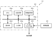
以下、本発明の第1の実施形態を、図面を参照しつつ説明する。図1は本実施形態に係る横断歩道検出システム10の概略的な構成を示すブロック図である。横断歩道検出システム10は、例えば自動車に搭載される。そして、撮像装置20によって撮像された画像に写る横断歩道を検出する。この横断歩道検出システム10は、図1に示されるように、撮像装置20と、撮像装置20によって撮像された画像から横断歩道を検出する横断歩道検出装置30とを有している。
<< First Embodiment >>
Hereinafter, a first embodiment of the present invention will be described with reference to the drawings. FIG. 1 is a block diagram showing a schematic configuration of a pedestrian
撮像装置20は、被写体を撮像することにより取得した画像PH1を電気信号に変換して出力するCCDカメラを含んで構成されている。この撮像装置20は、例えば自動車のフロントグリル、或いはバンパーなどに設置されている。
The
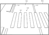
図2は、撮像装置20によって撮像された画像PH1の一例を示す図である。画像PH1には、道路100と、道路100の車線を区画するライン101と、道路100を横切る横断歩道120が写っている。この画像PH1を参照するとわかるように、撮像装置20は、その視野に、ライン101によって区画される車線が位置するように、視野角や倍率などが調整されている。そして、撮像装置20は、道路100を順次撮像し、撮像した画像に関する情報を出力する。
FIG. 2 is a diagram illustrating an example of an image PH1 captured by the
図1に戻り、横断歩道検出装置30は、記憶部31、画像変換部32、平均値算出部33、演算部34、曲線生成部35、判断部36を有している。
Returning to FIG. 1, the pedestrian
記憶部31は、撮像装置20から順次出力される画像に関する情報を時系列的に記憶する。また、上記各部32〜36の処理結果としての情報を順次記憶する。
The
画像変換部32は、撮像装置20によって撮像された画像PH1を、道路100を真上から見た画像(トップビュー画像)に変換する。具体的には、画像変換部32は、画像PH1に対して、座標変換処理を実行し、例えば図3に示される画像PH2を生成する。
The
ここで、画像PH2に、左下のコーナーを原点とするXY座標系を定義し、以下XY座標系を用いた説明を行う。 Here, an XY coordinate system with the lower left corner as the origin is defined in the image PH2, and description using the XY coordinate system will be given below.
画像PH1と画像PH2とを比較するとわかるように、画像PH2では、道路100の車線を区画するライン101がY軸とほぼ平行になっている。また、画像PH2では、横断歩道120を構成する白色パターン121それぞれは、長手方向をY軸方向とする長方形となっている。そして、各白色パターン121は、X軸方向に間隔D1で配置され、隣接する白色パターン121同士のエッジからエッジまでの距離d1は、白色パターン121のX軸方向の幅(大きさ)d2と等しい。
As can be seen by comparing the image PH1 and the image PH2, in the image PH2, the
画像変換部32は、画像PH2を生成すると、当該画像PH2を記憶部31に保存するとともに、画像PH1の変換処理が終了したことを平均値算出部33へ通知する。
When the
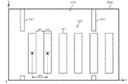
図4は、画像PH2と、当該画像PH2上に規定されたメインパターンMPを示す図である。平均値算出部33は、画像PH2上に、メインパターンMPを規定する。そして、このメインパターンMPを、画像PH1の中心を通りX軸に平行な直線L1と、X軸に平行で、直線L1から+Y方向に距離D2隔てた直線L2と、X軸に平行で、直線L1から−Y方向に距離D2隔てた直線L3とに沿って、例えば1〜数ピクセルずつ移動させながら各サブパターンSP1〜SP3と重なる画素の輝度の平均値を算出する。
FIG. 4 is a diagram illustrating the image PH2 and the main pattern MP defined on the image PH2. The average
このメインパターンMP及びサブパターンSP1〜SP3は、所定の形状をした領域もしくはウインドウである。上記動作により、当該領域もしくはウインドウ内の画素の輝度の平均値が算出される。 The main pattern MP and the sub patterns SP1 to SP3 are regions or windows having a predetermined shape. With the above operation, the average value of the luminance of the pixels in the area or window is calculated.
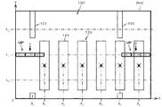
図5は、画像PH2上に規定されたメインパターンMPを拡大して示す図である。図5に示されるように、メインパターンMPは、X軸方向に配列された3つのサブパターンSP1〜SP3から構成されている。各サブパターンSP1〜SP3は、長手方向をX軸方向とする長方形である。そして、サブパターンSP1,SP3それぞれのX軸方向の寸法は、距離d1と等しく、サブパターンSP2の寸法は、距離d2と等しい。 FIG. 5 is an enlarged view showing the main pattern MP defined on the image PH2. As shown in FIG. 5, the main pattern MP includes three sub patterns SP1 to SP3 arranged in the X-axis direction. Each of the sub-patterns SP1 to SP3 is a rectangle whose longitudinal direction is the X-axis direction. The dimensions of the sub-patterns SP1 and SP3 in the X-axis direction are equal to the distance d1, and the dimension of the sub-pattern SP2 is equal to the distance d2.
図6は、平均値算出部33の動作を説明するための図である。図6を参照するとわかるように、平均値算出部33は、まず、画像PH2の中心を通りX軸に平行な直線L1に沿って、メインパターンMPを、矢印aに示される第1位置(2本のライン101に規定される車線の一側)から、矢印bに示される第2位置(車線の他側)まで移動させながら、各サブパターンSP1〜SP3と重なる画素の輝度の平均値を算出する。このとき、メインパターンMPは、車線(道路)を横切るように移動する。
FIG. 6 is a diagram for explaining the operation of the
具体的には、平均値算出部33は、第1位置にメインパターンMPを規定する。この位置では、メインパターンMPの中心は、直線L1上に位置する。また、メインパターンMPの−X側端は、画像PH2の−X側端に一致する。
Specifically, the average
次に、平均値算出部33は、メインパターンMPを、矢印aに示される第1位置から、矢印bに示される第2位置に向けて移動させながら、サブパターンSP1と重なる画素の輝度の平均値B11、サブパターンSP2と重なる画素の輝度の平均値B21、サブパターンSP3と重なる画素の輝度の平均値B31を順次算出する。そして、平均値算出部33は、算出した平均値B11,B21,B31を、当該平均値B11,B21,B31を算出したときのメインパターンMPの中心のX座標と関連づけて、データB11(X),B21(X),B31(X)として、記憶部31へ出力する。これにより、データB11(X),B21(X),B31(X)が、記憶部31に保存される。
Next, the average
平均値算出部33は、メインパターンMPが、その+X側端が、画像PH2の+X側端に一致する位置に達すると、メインパターンMPを、その中心が直線L2上に位置し、−X側端が画像PH2の−X側端に一致する位置に位置決めする。そして、この位置から、メインパターンMPを+X方向へ、直線L2に沿って移動させながら、サブパターンSP1と重なる画素の輝度の平均値B12、サブパターンSP2と重なる画素の輝度の平均値B22、サブパターンSP3と重なる画素の輝度の平均値B32を順次算出する。そして、平均値算出部33は、算出した平均値B12,B22,B32を、当該平均値B12,B22,B32を算出したときのメインパターンMPの中心のX座標と関連づけて、データB12(X),B22(X),B32(X)として、記憶部31へ出力する。これにより、データB12(X),B22(X),B32(X)が、記憶部31に保存される。
Average
平均値算出部33は、メインパターンMPが、その+X側端が、画像PH2の+X側端に一致する位置に達すると、メインパターンMPを、その中心が直線L3上に位置し、−X側端が画像PH2の−X側端に一致する位置に位置決めする。そして、この位置から、メインパターンMPを+X方向へ、直線L3沿って移動させながら、サブパターンSP1と重なる画素の輝度の平均値B13、サブパターンSP2と重なる画素の輝度の平均値B23、サブパターンSP3と重なる画素の輝度の平均値B33を順次算出する。そして、平均値算出部33は、算出した平均値B13,B23,B33を、当該平均値B13,B23,B33を算出したときのメインパターンMPの中心のX座標と関連づけて、データB13(X),B23(X),B33(X)として、記憶部31へ出力する。これにより、データB13(X),B23(X),B33(X)が、記憶部31に保存される。平均値算出部33は、上述の処理が終了すると、処理の終了を演算部34に通知する。
Average
以下、説明の便宜上、メインパターンMPを移動させながら、データB1N(X),B2N(X),B3N(X)を出力する動作をスキャン動作という。 Hereinafter, for convenience of explanation, an operation of outputting data B1 N (X), B2 N (X), and B3 N (X) while moving the main pattern MP is referred to as a scan operation.
演算部34は、データB1N(X),B2N(X),B3N(X)について、次式(1)で示される演算を実行する。なお、Nは1〜3までの整数を示す。
The
GN(X)=B2N(X)−(B1N(X)+B3N(X))/2 …(1) G N (X) = B 2 N (X) − (B 1 N (X) + B 3 N (X)) / 2 (1)
演算部34は、式(1)に示される演算が完了すると、演算結果GN(X)を記憶部31へ保存し、演算の完了を曲線生成部35へ通知する。
When the calculation shown in Expression (1) is completed, the
曲線生成部35は、演算部34による演算結果GN(X)に基づいて、特性曲線を生成する。具体的には、横軸をXとし、縦軸を演算結果GN(X)とする座標系に、Xの値と、演算結果GN(X)の値とによって規定される点をプロットし、プロットした点を通る特性曲線を生成する。
The
図7(A)に示されるように、メインパターンMPを構成するサブパターンSP2が、横断歩道120を構成する白色パターン121に完全に重なったときに、演算結果GN(X)が最大になる。その理由は、サブパターンSP2と重なる画素の輝度の平均値B2Nが最大となるとともに、サブパターンSP1,SP3と重なる画素の輝度の平均値B1N,B3Nがほぼ零となり、式(1)の演算結果GN(X)が最大となるためである。
As shown in FIG. 7A, when the sub-pattern SP2 constituting the main pattern MP completely overlaps the
また、図7(B)に示されるように、メインパターンMPを構成するサブパターンSP1,SP3が、横断歩道120を構成する白色パターン121に完全に重なったときに、演算結果GN(X)が最小になる。その理由は、サブパターンSP1,SP3と重なる画素の輝度の平均値B1N,B3Nが最大となるとともに、サブパターンSP2と重なる画素の輝度の平均値B2Nがほぼ零となり、式(1)の演算結果GN(X)が最小となるためである。
Further, as shown in FIG. 7B, when the sub-patterns SP1 and SP3 constituting the main pattern MP completely overlap with the
したがって、演算結果GN(X)が、横断歩道120を構成する白色パターン121を横切る直線に沿って、スキャン動作が行われた結果に基づく演算結果である場合には、特性曲線は、複数(例えば3つ以上)のピークを持った曲線となる。
Therefore, when the calculation result G N (X) is a calculation result based on the result of the scanning operation performed along the straight line crossing the
図8は、例えばスキャン動作が、図6における直線L1に沿って行われた結果に基づいて生成される特性曲線を示す図である。図8を参照するとわかるように、例えばスキャン動作が、直線L1に沿って行われた場合には、演算結果G1(X)は、Xの値が、白色パターン121それぞれの位置に対応するX1〜X6である場合にピークとなる。したがって、特性曲線は、5つのピークを持った曲線となる。
8, for example, the scanning operation is a diagram showing a characteristic curve which is generated based on the result performed along a straight line L 1 in FIG. As can be seen from FIG. 8, for example, when the scanning operation is performed along the straight line L 1 , the calculation result G 1 (X) has a value of X corresponding to the position of each
一方、演算結果GN(X)が、横断歩道120を構成する白色パターン121を横切らない直線に沿って、スキャン動作が行われた結果に基づく演算結果である場合には、特性曲線は、2つのピークを持った曲線となる。
On the other hand, when the calculation result G N (X) is a calculation result based on the result of the scanning operation performed along a straight line that does not cross the
図9は、例えばスキャン動作が、図6における直線L2に沿って行われた結果に基づいて生成される特性曲線を示す図である。図9に示されるように、例えばスキャン動作が、直線L2に沿って行われた場合には、演算結果G1(X)は、Xの値が、画像PH2におけるライン101それぞれの位置に対応するX0,X5である場合にピークとなる。したがって、特性曲線は、2つのピークを持った曲線となる。
9, for example, the scanning operation is a diagram showing a characteristic curve which is generated based on the result performed along a straight line L 2 in FIG. 6. As shown in FIG. 9, for example, when the scanning operation is performed along the straight line L 2 , the calculation result G 1 (X) indicates that the value of X corresponds to the position of each
曲線生成部35は、直線L1〜L3それぞれに沿って行ったスキャン動作ごとに特性曲線を生成する。そして、特性曲線に関する情報を記憶部31に出力するとともに、特性曲線の生成が完了したことを、判断部36に通知する。
The
判断部36は、生成された特性曲線の規則性に基づいて、画像PH2に横断歩道が写っているか否かを判断する。図10は、特性曲線の一例を示す図である。図10を参照するとわかるように、判断部36は、曲線の極大点をピークPとして検出する。そして、検出したピークPそれぞれのX座標XPNを特定する。次に、判断部36は、次式(2)で示される演算を実行し、特性曲線のピークPに対応するX座標XPN同士の差DPNを算出する。なお、式(2)におけるNは、N番目のピークに対応する整数である。式(2)の演算結果は、GN(X)が最大となるときの、画像PH2におけるメインパターンMPの位置相互間の距離と等しい。
The
DPN=XPN+1−XPN …(2) DP N = XP N + 1 −XP N (2)
スキャン動作が白色パターン121を横切る直線L1,L3(図6参照)に沿って実行された場合には、例えば図8に示される特性曲線が得られる。この場合は、ピークのX座標XPNは、画像PH2における白色パターン121のX座標XNに等しくなる。そして、式(2)の演算結果DPNは、白色パターン121の配列間隔D1に等しくなる。
When the scanning operation is executed along the straight lines L 1 and L 3 (see FIG. 6) crossing the
一方、スキャン動作が白色パターン121を横切らない直線L2に沿って実行された場合には、図9に示されるように、特性曲線のピークは3つより少なくなる。また、ピークが3つ以上であったとしても、式(2)の演算結果DPは、白色パターン121の配列間隔D1に等しくなることはないと考えられる。
On the other hand, when the scanning operation is performed along a straight line L 2 which does not cross the
そこで、判断部36は、特性曲線について、ピークが、例えば4つ以上検出された場合であって、N個の差DPNの値の過半数が、白色パターン121の配列間隔D1の値とほぼ等しいときに、スキャン動作が、横断歩道120の白色パターン121を横切る直線(例えば直線L1,L3)に沿って行われたものと判断する。なお、差DPNの値と、配列間隔D1の値との比較は、例えば差DPNの値と配列間隔D1の値との相違が閾値以下の時に等しいと判断する。
Therefore, the
一方、判断部36は、特性曲線について、ピークが3つ以上検出されなかった場合、又は、差DPNの値の過半数が、配列間隔D1の値と異なるときに、スキャン動作が、横断歩道120の白色パターン121を横切らない直線(例えば直線L2)に沿って行われたものと判断する。
On the other hand,
そして、判断部36は、直線L1〜L3に沿った3回のスキャン動作中、2回以上のスキャン動作が、横断歩道120の白色パターン121を横切る直線に沿って行われたと判断した場合に、画像PH2に横断歩道120が写っていると判断する。一方、直線L1〜L3に沿った3回のスキャン動作中、1回のスキャン動作のみが、横断歩道120の白色パターン121を横切る直線に沿って行われたと判断した場合、或いはすべてのスキャン動作が、白色パターン121を横切る直線に沿って行われなかったと判断した場合に、画像PH2に横断歩道120が写っていないと判断する。そして、画像PH2に横断歩道120が写っているか否かを判断した結果を外部装置等へ出力する。
When the
以上説明したように、本第1の実施形態では、メインパターンMPを用いたスキャン動作によって得られたデータB1N(X),B2N(X),B3N(X)について、式(1)に示される演算処理が実行される。次に、この演算処理の演算結果GN(X)と、メインパターンMPの画像PH2上の位置との関係を示す特性曲線が算出される。そして、特性曲線に現れるピークの規則性に基づいて、画像PH2に横断歩道が写っているか否かが判断される。 As described above, in the first embodiment, the data B1 N (X), B2 N (X), and B3 N (X) obtained by the scan operation using the main pattern MP are expressed by the equation (1). The arithmetic processing shown in FIG. Next, a characteristic curve indicating the relationship between the calculation result G N (X) of this calculation process and the position of the main pattern MP on the image PH2 is calculated. Then, based on the regularity of the peak appearing in the characteristic curve, it is determined whether or not a pedestrian crossing is shown in the image PH2.
上述のデータB1N(X),B2N(X),B3N(X)は、メインパターンMPのサブパターンSP1〜SP3それぞれと重なる画素の輝度の平均である。このため、横断歩道120を構成する白色パターン121に亀裂が生じていたり、白色パターン121に剥離が生じていたりしても、データB1N(X),B2N(X),B3N(X)の値は、ほとんど影響を受けない。
The above-mentioned data B1 N (X), B2 N (X), and B3 N (X) are average luminances of pixels that overlap with the sub-patterns SP1 to SP3 of the main pattern MP. For this reason, even if the
更に詳しくは、横断歩道120を構成する白色パターン121に亀裂が生じていたり、白色パターン121に剥離が生じていたりしても、これらの部分を表示する画素の数は、サブパターンSP1〜SP3と重なる画素の数パーセントにすぎない。このため、データB1N(X),B2N(X),B3N(X)の値は、白色パターン121に亀裂等があったとしても、ほとんど影響を受けることはない。したがって、横断歩道120の白色パターン121に経年劣化が生じたとしても、画像PH2に横断歩道が写っているか否かを精度よく判断することができる。
More specifically, even if the
なお、上記配列間隔D1、距離d1,d2の値それぞれは、実際の道路100における0.45mに対応する値である。また、直線L1〜L3相互間の距離D2は、実際の道路100における1.5mに対応する値である。また、メインパターンMPのY軸方向の寸法は、例えば画像PH2の画素と同等の大きさ(1ピクセルに相当する大きさ)である。ただし、メインパターンMPのY軸方向の寸法は、必要に応じて適宜変更してもよい。例えば、Y軸方向の寸法を、数ピクセル相当の大きさとしてもよい。
《第2の実施形態》
次に、本発明の第2の実施形態を、図11〜図17を参照しつつ説明する。なお、第1の実施形態と同一又は同等の構成については、同等の符号を用いるとともに、その説明を省略又は簡略する。
The values of the array interval D1 and the distances d1 and d2 are values corresponding to 0.45 m on the
<< Second Embodiment >>
Next, a second embodiment of the present invention will be described with reference to FIGS. In addition, about the structure same or equivalent to 1st Embodiment, while using an equivalent code | symbol, the description is abbreviate | omitted or simplified.
本実施形態に係る横断歩道検出システム10は、横断歩道検出装置30が、一般的なコンピュータ、又はマイクロコンピュータなどの装置と同様の構成によって実現されている点で、第1の実施形態に係る横断歩道検出システム10と相違している。
The pedestrian
図11は、横断歩道検出システム10の物理的な構成を示すブロック図である。図11に示されるように、横断歩道検出システム10は、撮像装置20と、コンピュータからなる横断歩道検出装置30とから構成されている。
FIG. 11 is a block diagram illustrating a physical configuration of the pedestrian
横断歩道検出装置30は、CPU(Central Processing Unit)30a、主記憶部30b、補助記憶部30c、表示部30d、入力部30e、インターフェイス部30f、及び上記各部を相互に接続するシステムバス30gを含んで構成されている。
The pedestrian
CPU30aは、補助記憶部30cに記憶されているプログラムに従って、撮像装置20から出力された画像PH1について、後述する処理を実行する。
CPU30a performs the process mentioned later about image PH1 output from the
主記憶部30bは、RAM(Random Access Memory)等を含んで構成され、CPU30aの作業領域として用いられる。
The
補助記憶部30cは、ROM(Read Only Memory)、磁気ディスク、半導体メモリ等の不揮発性メモリを含んで構成されている。この補助記憶部30cは、CPU30aが実行するプログラム、及び各種パラメータなどを記憶している。また、撮像装置20から出力される画像に関する情報、及びCPU30aによる処理結果などを含む情報を順次記憶する。
The
表示部30dは、CRT(Cathode Ray Tube)またはLCD(Liquid Crystal Display)などを含んで構成され、CPU30aの処理結果を表示する。
The
入力部30eは、キーボードやマウス等のポインティングデバイスを含んで構成されている。オペレータの指示は、この入力部30eを介して入力され、システムバス30gを経由してCPU30aに通知される。
The
インターフェイス部30fは、シリアルインターフェイスまたはLAN(Local Area Network)インターフェイス等を含んで構成されている。撮像装置20は、インターフェイス部30fを介してシステムバス30gに接続される。
The
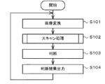
図12及び図13のフローチャートは、CPU30aによって実行されるプログラムの一連の処理アルゴリズムに対応している。以下、図12を参照しつつ、横断歩道検出装置30が実行する処理について説明する。なお、この処理は、横断歩道検出システム10が起動され、撮像装置20によって撮像された画像に関する情報が出力された後に実行される。また、前提として、撮像装置20からは、図2に示される画像PH1が出力されたものとする。
The flowcharts of FIGS. 12 and 13 correspond to a series of processing algorithms of a program executed by the
まず、最初のステップS101では、CPU30aは、撮像装置20によって撮像された画像PH1を、道路100を真上から見た画像(トップビュー画像)に変換する。具体的には、画像変換部32は、画像PH1に対して、座標変換処理を実行し、例えば図3に示される画像PH2を生成する。
First, in the first step S101, the
次のステップS102では、CPU30aは、画像PH2に対してスキャン処理を実行する。図12は、ステップS102で実行されるサブルーチンを示す図である。CPU30aは、ステップS102での処理を、図12に示されるサブルーチンを実行することにより実現する。
In the next step S102, the
サブルーチンにおける最初のステップS201では、CPU30aは、カウンタ値Nのリセットを行う。これにより、カウンタNの値が1に初期設定される。
In the first step S201 in the subroutine, the
次のステップS202では、CPU30aは、判定フラグをオフに設定する。
In the next step S202, the
次のステップS203では、CPU30aは、メインパターンを直線LN上の第1位置(図3における矢印aに示される位置)へ位置決めする。この位置では、メインパターンMPの中心は、直線L1上に位置する。また、メインパターンMPの−X側端は、画像PH2の−X側端に一致する。
In the next step S203, the
次のステップS204では、CPU30aは、サブパターンSP1と重なる画素の輝度の平均値B11、サブパターンSP2と重なる画素の輝度の平均値B21、サブパターンSP3と重なる画素の輝度の平均値B31を順次算出する。そして、各輝度平均値に、メインパターンMPのX座標を関連づけたデータB1N(X),B2N(X),B3N(X)を生成する。
In the next step S204, the
次のステップS205では、CPU30aは、データB1N(X),B2N(X),B3N(X)について、上記式(1)で示される演算を実行する。これにより、演算結果GN(X)が算出される。
In the next step S205, the
次のステップS206では、CPU30aは、演算結果GN(X)の値が、零以上の閾値A以上である否か判断する。図14は、直線L1に沿ってスキャン動作を行った結果から得られる特性曲線と、閾値A,Bとの関係が示されている。ここでは、メインパターンMPは、X座標が零となる第1位置にある。したがって、演算結果GN(X)は閾値Aより小さい。したがって、ステップS206での判断は否定され、CPU30aは、ステップS212へ移行する。
In the next step S206, the
ステップS212では、CPU30aは、演算結果GN(X)の値が、零以下の閾値B以下である否か判断する。図14に示されるように、ここでは、演算結果GN(X)は閾値B以下である。したがって、CPU30aは、ステップS213へ移行する。
In step S212, the
ステップS213では、CPU30aは、判定フラグをオフに設定する。
In step S213, the
ステップS214では、CPU30aは、メインパターンMPが第2位置(図6における矢印bに示される位置)にあるか否か判断する。ここでは、メインパターンMPは、第1位置にあるので、ステップS214での判断は否定され、CPU30aは、次のステップS215へ移行する。
In step S214, the
ステップS215では、CPU30aは、メインパターンMPの位置を、+X方向へ微小距離移動させる。そして、ステップS204へ戻る。
In step S215, the
以降、CPU30aによって、ステップS204〜S206の処理,及びステップS212〜S215の処理が繰り返し実行されると、メインパターンMPがX方向へ移動し、それに伴い、演算結果GN(X)の値は、図14の特性曲線に示されるように推移する。やがて、演算結果GN(X)の値は、閾値A以下で、かつ閾値Bより大きくなる。この場合は、ステップS212での判断が否定され、CPU30aは、ステップS214へ直接移行する。
Thereafter, when the processing of steps S204 to S206 and the processing of steps S212 to S215 are repeatedly executed by the
次に、CPU30aによって、ステップS204〜S206の処理、及びS212,S214,S215の処理が繰り返し実行されると、演算結果GN(X)の値は、閾値Bより大きくなる。この場合は、ステップS206での判断が肯定され、CPU30aは、ステップS207へ移行する。
Next, when the processing of steps S204 to S206 and the processing of S212, S214, and S215 are repeatedly executed by the
ステップS207では、CPU30aは、判定フラグがオフであるか否か判断する。ここでは、判定フラグはオフである。したがって、ステップS207での判断が肯定され、CPU30aは、ステップS208へ移行する。
In step S207, the
ステップS208では、CPU30aは、演算結果GN(X)をピーク値として、記憶部31へ保存する。
In step S208, the
次のステップS209では、CPU30aは、判定フラグをオンに設定する。
In the next step S209, the
次に、CPU30aは、ステップS214,S215の処理を実行した後、ステップS204〜S206の処理を実行する。この時点では、判定フラグがオンに設定されている。したがって、ステップS207での判断は否定される。この場合、CPU30aは、ステップS210へ移行する。
Next, after executing the processes of steps S214 and S215, the
ステップS210では、CPU30aは、演算結果GN(X)が、直近に保存された演算結果GN−1(X)よりも大きいか判断する。メインパターンMPのX座標が、X1以下である場合には、ステップS210での判断は肯定され、CPU30aは、ステップS211へ移行する。
In step S210,
ステップS211では、CPU30aは、演算結果GN(X)をピーク値として保存する。これにより、演算結果GN(X)が更新される。
In step S211, the
以降、CPU30aによって、ステップS214,S215,ステップS204〜S207,及びステップ210,S211の処理が繰り返し実行されることで、図15中に白○で示されるように、ピーク値が更新される。
Thereafter, the
一方、メインパターンMPのX座標が、X1を超えると、ステップS210での判断は否定され、CPU30aは、ステップS214へ移行する。
On the other hand, X-coordinate of the main pattern MP is more than X 1, the determination in step S210 is negative,
以降、メインパターンMPが第2位置まで移動し、ステップS214での判断が肯定されるまで、ステップS201〜S215までの処理が繰り返し実行される。これにより、直線L1に沿ったスキャン動作が完了し、図16に白丸で示されるようにピークが更新され、最終的に複数のピークP1が決定する。 Thereafter, the processes from step S201 to S215 are repeatedly executed until the main pattern MP moves to the second position and the determination in step S214 is affirmed. Thus, by scanning motion along the straight line L 1 is completed, the peak as indicated by a white circle is updated in FIG. 16, finally plurality of peaks P 1 is determined.
ステップS214での判断が肯定されると、CPU30aは、ステップS216へ移行する。
If the determination in step S214 is affirmative, the
ステップS216では、CPU30aは、カウンタ値Nが3であるか否か判断する。ここでは、カウンタ値Nは1であるため、ステップS216の判断は否定され、CPU30aは、ステップS217へ移行する。
In step S216, the
ステップS217では、CPU30aは、カウンタ値Nを1インクリメントし、ステップS203へ戻る。
In step S217, the
以降、カウンタ値が3となり、ステップS216での判断が肯定されるまで、S201〜S214の処理が繰り返し実行される。これにより、直線L2に沿ったスキャン動作が行われ、最終的に、図17に示される複数(2つ)のピークP2が決定する。また、直線L3に沿ったスキャン動作が行われ、最終的に、複数のピークP3が決定する。 Thereafter, the processing of S201 to S214 is repeatedly executed until the counter value becomes 3 and the determination in step S216 is affirmed. Thereby, a scanning operation along the straight line L 2 is performed, and finally, a plurality (two) of peaks P 2 shown in FIG. 17 are determined. Also, it is performed scanning operation along a straight line L 3, and finally, a plurality of peaks P 3 is determined.
カウンタ値Nが3になり、ステップS216での判断が肯定されると、CPU30aは、サブルーチンを終了し、ステップS103に移行する。
When the counter value N becomes 3 and the determination in step S216 is affirmative, the
次のステップ103では、ステップ102のスキャン処理によって決定したピークPに基づいて、画像PH2に横断歩道120が写っているか否かを判断する。
In the
例えば、CPU30aは、直線LNに沿ったスキャン動作ごとに、ピークPN,MのX座標XPMを特定する。なお、ここでのNはラインナンバーを表し、Mはピークナンバーを表している。そして、図16に示されるX座標XPM同士の差DPNを算出する。次に、ピークが、例えば4つ以上検出された場合であって、N個の差DPNの値の過半数が、白色パターン121の配列間隔D1の値とほぼ等しいときに、スキャン動作が、横断歩道120の白色パターン121を横切る直線(例えば直線L1,L3)に沿って行われたものと判断する。
For example, the
一方、CPU30aは、特性曲線について、ピークが3つ以上検出されなかった場合、又は、差DPNの値と、配列間隔D1の値とが異なるときに、スキャン動作が、横断歩道120の白色パターン121を横切らない直線(例えば直線L2)に沿って行われたものと判断する。
Meanwhile,
そして、CPU30aは、直線L1〜L3に沿った3回のスキャン動作中、2回以上のスキャン動作が、横断歩道120の白色パターン121を横切る直線に沿って行われたと判断した場合に、画像PH2に横断歩道120が写っていると判断する。一方、直線L1〜L3に沿った3回のスキャン動作中、1回のスキャン動作のみが、横断歩道120の白色パターン121を横切る直線に沿って行われたと判断した場合、或いはすべてのスキャン動作が、白色パターン121を横切る直線に沿って行われなかったと判断した場合に、画像PH2に横断歩道120が写っていない判断する。
Then,
次のステップS104では、CPU30aは、画像PH2に横断歩道120が写っているか否かを判断した結果を外部装置等へ出力する。
In the next step S104, the
以上説明したように、本第2の実施形態では、メインパターンMPを用いたスキャン動作によって得られたデータB1N(X),B2N(X),B3N(X)について、式(1)に示される演算処理が実行される。次に、演算結果GN(X)と、メインパターンMPの画像PH2上の位置との関係を示す特性曲線のピークが決定され、このピークの規則性に基づいて、画像PH2に横断歩道が写っているか否かが判断される。 As described above, in the second embodiment, the data B1 N (X), B2 N (X), and B3 N (X) obtained by the scan operation using the main pattern MP are expressed by the equation (1). The arithmetic processing shown in FIG. Next, the peak of the characteristic curve indicating the relationship between the calculation result G N (X) and the position of the main pattern MP on the image PH2 is determined. Based on the regularity of this peak, a pedestrian crossing is reflected in the image PH2. It is determined whether or not.
上述のデータB1N(X),B2N(X),B3N(X)は、メインパターンMPのサブパターンSP1〜SP3それぞれと重なる画素の輝度の平均である。このため、横断歩道120を構成する白色パターン121に亀裂が生じていたり、白色パターン121に剥離が生じていたりしても、データB1N(X),B2N(X),B3N(X)の値は、ほとんど影響を受けない。したがって、横断歩道120の白色パターン121に経年劣化が生じたとしても、画像PH2に横断歩道が写っているか否かを精度よく判断することができる。
The above-mentioned data B1 N (X), B2 N (X), and B3 N (X) are average luminances of pixels that overlap with the sub-patterns SP1 to SP3 of the main pattern MP. For this reason, even if the
また、本実施形態では、3つ以上のピークが特定された後も、スキャン動作を行った。これに限らず、スキャン動作において、例えばピークが2つ特定できたら、当該スキャン動作を停止し、ピークのX座標XP1とX座標XP2相互間の差DP1を算出する。そして、この差DP1が、白色パターン121の配列間隔D1の値とほぼ等しいときに、当該スキャン動作が白色パターン121を横切る直線に沿って行われたものと判断してもよい。
In this embodiment, the scanning operation is performed even after three or more peaks are specified. For example, if two peaks can be identified in the scanning operation, the scanning operation is stopped, and the difference DP 1 between the X coordinate XP 1 and the X coordinate XP 2 of the peak is calculated. Then, when the difference DP 1 is substantially equal to the value of the arrangement interval D 1 of the
以上、本発明の実施形態について説明したが、本発明は上記実施形態によって限定されるものではない。 As mentioned above, although embodiment of this invention was described, this invention is not limited by the said embodiment.
例えば、上記実施形態では、直線L1〜L3それぞれに沿って、3回のスキャン動作を行った。これに限らず、横断歩道検出システム10は、スキャン動作を、4回以上行ってもよい。また、1回のスキャン動作で、画像PH2に横断歩道が写っているか否かを判断してもよい。また、この場合に、画像の上方から順次スキャン動作を実施し、横断歩道が写っていると判断された場合にスキャンを停止する形態が考えられる。
For example, in the above embodiment, the scan operation is performed three times along each of the straight lines L 1 to L 3 . Not only this but the pedestrian
また、上記実施形態では、直線L1が画像PH1の中心を通ることとした。これに限らず、直線L1は、画像PH1の中心を通る直線でなくともよい。画像PHにおける直線L1〜L3の位置は、例えば車種や、撮像装置20の取り付け位置、その他の条件に応じて、適当な位置とすることができる。
In the above embodiment, the straight line L 1 has a passing through the center of the image PH1. Not limited thereto, the straight line L 1 may not be a straight line passing through the center of the image PH1. The positions of the straight lines L 1 to L 3 in the image PH can be set to appropriate positions according to, for example, the vehicle type, the mounting position of the
また、上記実施形態では、サブパターンSP1〜SP3と重なる画素の輝度の平均値を用いて、画像PHに写る横断歩道を検出した。これに限らず、サブパターンSP1〜SP3と重なる画素の輝度の総和等を用いて、画像PHに写る横断歩道を検出してもよい。 Moreover, in the said embodiment, the pedestrian crossing reflected on the image PH was detected using the average value of the brightness | luminance of the pixel which overlaps with subpattern SP1-SP3. However, the present invention is not limited to this, and a crosswalk that appears in the image PH may be detected using the sum of the luminances of pixels that overlap the sub-patterns SP1 to SP3.
また、上記実施形態では、メインパターンMPが3つのサブパターンSP1〜SP3から構成されている場合について説明した。これに限らず、メインパターンMPが、サブパターンSP1及びサブパターンSP2のみから構成されていてもよい。この場合は、演算部34は、データB1N(X),B2N(X)について、次式(3)で示される演算を実行すればよい。
In the above-described embodiment, the case where the main pattern MP is composed of three sub patterns SP1 to SP3 has been described. Not limited to this, the main pattern MP may be composed of only the sub-pattern SP1 and the sub-pattern SP2. In this case, the
GN(X)=B2N(X)−B1N(X) …(3) G N (X) = B2 N (X) -B1 N (X) ... (3)
また、上記実施形態では、式(1)を用いた演算を行ったが、これに限らず、例えば、次式(4)、或いは次式(5)に基づく演算を行ってもよい。例えば、式(4)、及び式(5)では、係数k1の値を2、係数k2の値を1とすることができる。 Moreover, in the said embodiment, although the calculation using Formula (1) was performed, it is not restricted to this, For example, you may perform the calculation based on following Formula (4) or following Formula (5). For example, in the expressions (4) and (5), the value of the coefficient k 1 can be 2 and the value of the coefficient k 2 can be 1.
GN(X)=k1・B2N(X)−k2・(B1N(X)+B3N(X))/2 …(4)
GN(X)=k1・B2N(X)−k2・B1N(X) …(5)
G N (X) = k 1 · B 2 N (X) −k 2 · (B 1 N (X) + B 3 N (X)) / 2 (4)
G N (X) = k 1 · B 2 N (X) −k 2 · B 1 N (X) (5)
また、上記実施形態では、メインパターンMPを、ライン101によって区画される車線の一側にある第1位置から、他側にある第2位置へ移動させることにより、スキャン動作を実行した。これに限らず、画像に横断歩道120全体が写っている場合には、メインパターンMPを、道路100の一側(+X側)から他側(−X側)へ移動させることにより、スキャン動作を実行してもよい。
In the above-described embodiment, the scanning operation is performed by moving the main pattern MP from the first position on one side of the lane divided by the
また、上記実施形態では、メインパターンMPを、その−X側端が画像PH2の−X側端と一致する位置から、+X方向へ移動させることにより、スキャン動作を実行した。これに限らず、道路100のライン101の位置がわかっている場合、具体的には、ライン101を画像処理等により予め検出した場合には、例えば図3に示される2本のライン101の間で、メインパターンMPを移動させて、スキャン動作を実行することとしてもよい。
In the above-described embodiment, the scanning operation is performed by moving the main pattern MP in the + X direction from the position where the −X side end coincides with the −X side end of the image PH2. Not limited to this, when the position of the
この場合、メインパターンMPを移動させる距離が少なくなるので、横断歩道検出システム10が取り扱う情報量が少なくなる。その結果、横断歩道検出システム10は、短時間に処理を完結することが可能となる。
In this case, since the distance for moving the main pattern MP is reduced, the amount of information handled by the pedestrian
また、上記実施形態では、撮像装置20によって撮像された画像PH1を、画像PH2に変換したがこれに限らず、画像PH1に直接メインパターンMPを規定し、このメインパターンMPを用いてスキャン動作を行ってもよい。具体的には、画像変換部32による変換が行われる前の画像PH1上に、画像PH2と同様に、左下のコーナーを原点とするXY座標系と、メインパターンMPとを規定する。そして、このメインパターンMPを用いて、画像PH1に対するスキャン動作を行う。この場合、メインパターンMPのY座標に応じて、メインパターンMPのX軸方向の寸法を適当に変更する必要がある。その理由は、車両の前方の道路100を撮影した画像PH1では、画像PH1に写る道路100は、画像PH1の焦点に近づくにつれて(撮像装置20から遠くなるにつれて)、幅が小さくなるためである。
Moreover, in the said embodiment, although image PH1 imaged with the
また、上記実施形態では、サブパターンSP1〜SP3同士が隣接している場合について説明した。これに限らず、サブパターンSP1〜SP3同士は、所定のクリアランスを介して配置されていてもよい。例えば、図5における各サブパターンSP1〜SP3を、中心位置をそのままに、X軸方向の寸法を例えば0.1m小さくし、これらのサブパターンSP1〜SP3から、メインパターンMPを構成してもよい。 Moreover, in the said embodiment, the case where sub pattern SP1-SP3 adjoins was demonstrated. Not limited to this, the sub-patterns SP1 to SP3 may be arranged via a predetermined clearance. For example, the sub-patterns SP1 to SP3 in FIG. 5 may be formed by reducing the dimension in the X-axis direction by, for example, 0.1 m while maintaining the center position, and the main pattern MP may be configured from these sub-patterns SP1 to SP3. .
また、上記各実施形態に係る横断歩道検出装置30の機能は、専用のハードウェアによっても、また、通常のコンピュータシステムによっても実現することができる。
In addition, the function of the pedestrian
また、第2の実施形態において横断歩道検出装置30の補助記憶部30cに記憶されているプログラムは、フレキシブルディスク、CD−ROM(Compact Disk Read-Only Memory)、DVD(Digital Versatile Disk)、MO(Magneto-Optical disk)等のコンピュータで読み取り可能な記録媒体に格納して配布し、そのプログラムをコンピュータにインストールすることにより、上述の処理を実行する装置を構成することとしてもよい。
In the second embodiment, programs stored in the
また、プログラムをインターネット等の通信ネットワーク上の所定のサーバ装置が有するディスク装置等に格納しておき、例えば、搬送波に重畳させて、コンピュータにダウンロード等するようにしても良い。 Further, the program may be stored in a disk device or the like included in a predetermined server device on a communication network such as the Internet, and may be downloaded onto a computer by being superimposed on a carrier wave, for example.
また、プログラムは、通信ネットワークを介して転送しながら起動実行することとしてもよい。 Further, the program may be activated and executed while being transferred via a communication network.
また、プログラムは、全部又は一部をサーバ装置上で実行させ、その処理に関する情報を通信ネットワークを介して送受信しながら、上述の画像処理を実行することとしてもよい。 The program may be executed entirely or partially on the server device, and the above-described image processing may be executed while transmitting / receiving information regarding the processing via the communication network.
なお、上述の機能を、OS(Operating System)が分担して実現する場合又はOSとアプリケーションとの協働により実現する場合等には、OS以外の部分のみを媒体に格納して配布してもよく、また、コンピュータにダウンロード等しても良い。 Note that when the above functions are realized by sharing an OS (Operating System) or when the functions are realized by cooperation between the OS and an application, only the part other than the OS may be stored in a medium and distributed. It may also be downloaded to a computer.
本発明は、本発明の広義の精神と範囲を逸脱することなく、様々な実施形態及び変形が可能とされるものである。また、上述した実施形態は、本発明を説明するためのものであり、本発明の範囲を限定するものではない。 Various embodiments and modifications can be made to the present invention without departing from the broad spirit and scope of the present invention. Further, the above-described embodiment is for explaining the present invention, and does not limit the scope of the present invention.
本発明の横断歩道検出装置、横断歩道検出システム,横断歩道検出方法及びプログラムは、画像に写る横断歩道の検出に適している。 The pedestrian crossing detection apparatus, the pedestrian crossing detection system, the pedestrian crossing detection method, and the program according to the present invention are suitable for detecting a pedestrian crossing reflected in an image.
10 横断歩道検出システム
20 撮像装置
30 横断歩道検出装置
30a CPU
30b 主記憶部
30c 補助記憶部
30d 表示部
30e 入力部
30f インターフェイス部
30g システムバス
31 記憶部
32 画像変換部
33 平均値算出部
34 演算部
35 曲線生成部
36 判断部
100 道路
101 ライン
120 横断歩道
121 白色パターン
MP メインパターン
PH1 画像
PH2 画像
SP1 サブパターン
SP2 サブパターン
SP3 サブパターン
DESCRIPTION OF
30b
Claims (11)
前記画像に写る前記横断歩道を構成する白色パターンに対応する第1サブパターンと、前記白色パターンに挟まれる領域に対応する第2サブパターンとを有するメインパターンを、前記画像上の第1位置から、前記第1位置とは異なる第2位置まで移動させながら、前記第1サブパターンと重なる画素の輝度に基づいて演算された第1演算値と、前記第2サブパターンと重なる画素の輝度に基づいて演算された第2演算値とを算出する算出手段と、
前記第1演算値と前記第2演算値とを用いた演算を行う演算手段と、
前記メインパターンの位置と前記演算手段による演算の結果との関係の規則性に基づいて、前記第1位置と前記第2位置の間に、前記横断歩道の画像が存在するか否かを判断する判断手段と、
を備える横断歩道検出装置。 A pedestrian crossing detection device that detects the pedestrian crossing from an image of a pedestrian crossing across a road,
A main pattern having a first sub-pattern corresponding to a white pattern constituting the pedestrian crossing reflected in the image and a second sub-pattern corresponding to a region sandwiched between the white patterns from a first position on the image , Based on the first calculated value calculated based on the luminance of the pixel overlapping the first sub pattern and the luminance of the pixel overlapping the second sub pattern while moving to a second position different from the first position. Calculating means for calculating the second calculated value calculated in the step;
A calculation means for performing a calculation using the first calculation value and the second calculation value;
It is determined whether an image of the pedestrian crossing exists between the first position and the second position based on the regularity of the relationship between the position of the main pattern and the calculation result by the calculation means. Judgment means,
A pedestrian crossing detector.
前記画像に写る前記横断歩道を構成する白色パターンに対応する第1サブパターンと、前記白色パターンに挟まれる領域に対応する第2サブパターンとを有するメインパターンを、前記画像上の第1位置から、前記第1位置とは異なる第2位置まで移動させながら、前記第1サブパターンと重なる画素の輝度に基づいて演算された第1演算値と、前記第2サブパターンと重なる画素の輝度に基づいて演算された第2演算値とを算出する工程と、
前記第1演算値と前記第2演算値とを用いた演算を行う工程と、
前記メインパターンの位置と、前記第1演算値と前記第2演算値とを用いた演算の結果と、の関係の規則性に基づいて、前記第1位置と前記第2位置の間に、前記横断歩道の画像が存在するか否かを判断する工程と、
を含む横断歩道検出方法。 A pedestrian crossing detection method for detecting the pedestrian crossing from an image showing a pedestrian crossing across a road,
A main pattern having a first sub-pattern corresponding to a white pattern constituting the pedestrian crossing reflected in the image and a second sub-pattern corresponding to a region sandwiched between the white patterns from a first position on the image , Based on the first calculated value calculated based on the luminance of the pixel overlapping the first sub pattern and the luminance of the pixel overlapping the second sub pattern while moving to a second position different from the first position. Calculating a second calculated value calculated by
Performing a calculation using the first calculation value and the second calculation value;
Based on the regularity of the relationship between the position of the main pattern and the calculation result using the first calculation value and the second calculation value, between the first position and the second position, Determining whether a pedestrian crossing image exists;
Crosswalk detection method including
画像に写る前記横断歩道を構成する白色パターンに対応する第1サブパターンと、前記白色パターンに挟まれる領域に対応する第2サブパターンとを有するメインパターンを、前記画像上の第1位置から、前記第1位置とは異なる第2位置まで移動させながら、前記第1サブパターンと重なる画素の輝度に基づいて演算された第1演算値と、前記第2サブパターンと重なる画素の輝度に基づいて演算された第2演算値とを算出する算出手段と、
前記第1演算値と前記第2演算値とを用いた演算を行う演算手段と、
前記メインパターンの位置と前記演算手段による演算の結果との関係の規則性に基づいて、前記第1位置と前記第2位置の間に、前記横断歩道の画像が存在するか否かを判断する判断手段と、
として機能させるプログラム。 Computer
A main pattern having a first sub-pattern corresponding to a white pattern constituting the pedestrian crossing in the image and a second sub-pattern corresponding to a region sandwiched between the white patterns, from a first position on the image, While moving to a second position different from the first position, based on the first calculation value calculated based on the luminance of the pixel overlapping the first sub pattern and the luminance of the pixel overlapping the second sub pattern. A calculating means for calculating the calculated second calculated value;
A calculation means for performing a calculation using the first calculation value and the second calculation value;
It is determined whether an image of the pedestrian crossing exists between the first position and the second position based on the regularity of the relationship between the position of the main pattern and the calculation result by the calculation means. Judgment means,
Program to function as.
Priority Applications (5)
| Application Number | Priority Date | Filing Date | Title |
|---|---|---|---|
| JP2010058286A JP5035371B2 (en) | 2010-03-15 | 2010-03-15 | Crosswalk detection device, crosswalk detection system, crosswalk detection method and program |
| DE112011100928T DE112011100928T5 (en) | 2010-03-15 | 2011-03-08 | Pedestrian crossing detection device, pedestrian crossing detection method and program |
| PCT/JP2011/055384 WO2011114947A1 (en) | 2010-03-15 | 2011-03-08 | Crosswalk detection device, crosswalk detection device method and program |
| CN201180011768.3A CN102782725B (en) | 2010-03-15 | 2011-03-08 | Crosswalk detection device, crosswalk detection device method and program |
| US13/583,868 US8600112B2 (en) | 2010-03-15 | 2011-03-08 | Crosswalk detection device, crosswalk detection method and recording medium |
Applications Claiming Priority (1)
| Application Number | Priority Date | Filing Date | Title |
|---|---|---|---|
| JP2010058286A JP5035371B2 (en) | 2010-03-15 | 2010-03-15 | Crosswalk detection device, crosswalk detection system, crosswalk detection method and program |
Publications (3)
| Publication Number | Publication Date |
|---|---|
| JP2011192071A JP2011192071A (en) | 2011-09-29 |
| JP2011192071A5 JP2011192071A5 (en) | 2012-07-05 |
| JP5035371B2 true JP5035371B2 (en) | 2012-09-26 |
Family
ID=44649045
Family Applications (1)
| Application Number | Title | Priority Date | Filing Date |
|---|---|---|---|
| JP2010058286A Expired - Fee Related JP5035371B2 (en) | 2010-03-15 | 2010-03-15 | Crosswalk detection device, crosswalk detection system, crosswalk detection method and program |
Country Status (5)
| Country | Link |
|---|---|
| US (1) | US8600112B2 (en) |
| JP (1) | JP5035371B2 (en) |
| CN (1) | CN102782725B (en) |
| DE (1) | DE112011100928T5 (en) |
| WO (1) | WO2011114947A1 (en) |
Families Citing this family (14)
| Publication number | Priority date | Publication date | Assignee | Title |
|---|---|---|---|---|
| JP5836774B2 (en) * | 2011-11-28 | 2015-12-24 | 三菱電機株式会社 | Overhead video generation device, overhead video generation method, video display system, and navigation device |
| KR101440293B1 (en) * | 2012-02-16 | 2014-09-17 | 팅크웨어(주) | Apparatus and method for detecting crosswalk |
| JP6205712B2 (en) * | 2012-03-02 | 2017-10-04 | 日産自動車株式会社 | Crosswalk detector and pedestrian crossing detection method |
| JP6082802B2 (en) | 2013-02-27 | 2017-02-15 | 日立オートモティブシステムズ株式会社 | Object detection device |
| CN104680171B (en) * | 2013-11-27 | 2018-10-02 | 富士通株式会社 | The detection device, method of zebra stripes in image |
| CN104268513B (en) * | 2014-09-17 | 2017-10-31 | 百度在线网络技术(北京)有限公司 | Road guides the acquisition methods and device of data |
| CN104331708B (en) * | 2014-11-05 | 2017-11-10 | 武汉大学 | A kind of zebra crossing automatic detection analysis method and system |
| KR102383425B1 (en) * | 2014-12-01 | 2022-04-07 | 현대자동차주식회사 | Electronic apparatus, control method of electronic apparatus, computer program and computer readable recording medium |
| US9846969B2 (en) | 2014-12-01 | 2017-12-19 | Thinkware Corporation | Electronic apparatus, control method thereof, computer program, and computer-readable recording medium |
| US11124163B2 (en) * | 2016-01-29 | 2021-09-21 | Nissan Motor Co., Ltd. | Method for controlling travel of vehicle, and device for controlling travel of vehicle |
| KR20180122691A (en) * | 2016-03-24 | 2018-11-13 | 닛산 지도우샤 가부시키가이샤 | Mainly a detection method and mainly a detection device |
| CN107049717B (en) * | 2016-11-23 | 2019-03-01 | 杭州视氪科技有限公司 | One kind is based on RGB-D camera and stereosonic visually impaired people's zebra stripes detection system and method |
| JP7032280B2 (en) * | 2018-10-11 | 2022-03-08 | トヨタ自動車株式会社 | Pedestrian crossing marking estimation device |
| US10915762B1 (en) * | 2018-12-07 | 2021-02-09 | Waymo Llc | Sidewalk detection for pedestrian behavior modeling |
Family Cites Families (26)
| Publication number | Priority date | Publication date | Assignee | Title |
|---|---|---|---|---|
| SE394146B (en) * | 1975-10-16 | 1977-06-06 | L Olesen | SATURATION DEVICE RESP CONTROL OF A FOREMAL, IN ESPECIALLY THE SPEED OF A VEHICLE. |
| JP3153845B2 (en) * | 1995-05-12 | 2001-04-09 | 三菱電機株式会社 | Road surface monitoring device and road surface monitoring method |
| JP3833001B2 (en) * | 1999-04-12 | 2006-10-11 | 積水樹脂株式会社 | Road marking system |
| JP3352655B2 (en) | 1999-09-22 | 2002-12-03 | 富士重工業株式会社 | Lane recognition device |
| JP2002329297A (en) * | 2001-04-27 | 2002-11-15 | Nippon Signal Co Ltd:The | System for detecting danger |
| JP4327389B2 (en) * | 2001-10-17 | 2009-09-09 | 株式会社日立製作所 | Travel lane recognition device |
| JP3736463B2 (en) * | 2002-01-23 | 2006-01-18 | 石川島播磨重工業株式会社 | Pedestrian response signal control method |
| JP3964230B2 (en) * | 2002-03-01 | 2007-08-22 | アルパイン株式会社 | Car navigation system |
| JP3977776B2 (en) * | 2003-03-13 | 2007-09-19 | 株式会社東芝 | Stereo calibration device and stereo image monitoring device using the same |
| JP2004310522A (en) | 2003-04-08 | 2004-11-04 | Toyota Motor Corp | Vehicular image processor |
| DE10349631A1 (en) * | 2003-10-24 | 2005-05-19 | Robert Bosch Gmbh | Driver assistance method and apparatus based on lane information |
| WO2006045259A1 (en) * | 2004-10-27 | 2006-05-04 | Robert Bosch Gmbh | Method for improving the security of users of a route, who are involved in an accident that has been foreseen |
| JP2006190188A (en) * | 2005-01-07 | 2006-07-20 | Toyota Motor Corp | Region dividing method |
| JP4568637B2 (en) | 2005-04-26 | 2010-10-27 | 富士重工業株式会社 | Road recognition device |
| JP4822766B2 (en) * | 2005-08-18 | 2011-11-24 | 富士通株式会社 | Road marking recognition device and system |
| JP5022609B2 (en) * | 2006-02-27 | 2012-09-12 | 日立オートモティブシステムズ株式会社 | Imaging environment recognition device |
| JP4248558B2 (en) * | 2006-03-24 | 2009-04-02 | トヨタ自動車株式会社 | Road marking line detection device |
| JP2007264712A (en) | 2006-03-27 | 2007-10-11 | Fuji Heavy Ind Ltd | Lane detector |
| US8204278B2 (en) * | 2006-11-28 | 2012-06-19 | Fujitsu Limited | Image recognition method |
| JP4886597B2 (en) * | 2007-05-25 | 2012-02-29 | アイシン・エィ・ダブリュ株式会社 | Lane determination device, lane determination method, and navigation device using the same |
| JP5395385B2 (en) | 2008-09-01 | 2014-01-22 | 学校法人東海大学 | Method for producing carbon fiber reinforced thermoplastic resin molded body and carbon fiber reinforced thermoplastic resin molded body |
| JP5361541B2 (en) * | 2009-06-02 | 2013-12-04 | 三菱電機株式会社 | Sign recognition device |
| US8953838B2 (en) * | 2009-06-24 | 2015-02-10 | Here Global B.V. | Detecting ground geographic features in images based on invariant components |
| CN101620732A (en) * | 2009-07-17 | 2010-01-06 | 南京航空航天大学 | Visual detection method of road driving line |
| JP5631581B2 (en) | 2009-12-01 | 2014-11-26 | 富士重工業株式会社 | Road recognition device |
| JP5220787B2 (en) * | 2010-03-08 | 2013-06-26 | 株式会社日本自動車部品総合研究所 | In-vehicle white line recognition device |
-
2010
- 2010-03-15 JP JP2010058286A patent/JP5035371B2/en not_active Expired - Fee Related
-
2011
- 2011-03-08 US US13/583,868 patent/US8600112B2/en not_active Expired - Fee Related
- 2011-03-08 DE DE112011100928T patent/DE112011100928T5/en not_active Withdrawn
- 2011-03-08 CN CN201180011768.3A patent/CN102782725B/en not_active Expired - Fee Related
- 2011-03-08 WO PCT/JP2011/055384 patent/WO2011114947A1/en active Application Filing
Also Published As
| Publication number | Publication date |
|---|---|
| DE112011100928T5 (en) | 2013-01-24 |
| US8600112B2 (en) | 2013-12-03 |
| JP2011192071A (en) | 2011-09-29 |
| WO2011114947A1 (en) | 2011-09-22 |
| US20130016915A1 (en) | 2013-01-17 |
| CN102782725A (en) | 2012-11-14 |
| CN102782725B (en) | 2014-06-11 |
Similar Documents
| Publication | Publication Date | Title |
|---|---|---|
| JP5035371B2 (en) | Crosswalk detection device, crosswalk detection system, crosswalk detection method and program | |
| CN113486797B (en) | Unmanned vehicle position detection method, unmanned vehicle position detection device, unmanned vehicle position detection equipment, storage medium and vehicle | |
| US11763575B2 (en) | Object detection for distorted images | |
| JP4367475B2 (en) | Moving object recognition apparatus, moving object recognition method, and computer program | |
| JP3759429B2 (en) | Obstacle detection apparatus and method | |
| US9454704B2 (en) | Apparatus and method for determining monitoring object region in image | |
| US20070291987A1 (en) | Vehicle surroundings monitoring apparatus | |
| KR100816377B1 (en) | Method and Apparatus for Recognizing Parking Slot Marking by Using Hough Transformation and Parking Assist System Using Same | |
| JP4416039B2 (en) | Striped pattern detection system, striped pattern detection method, and striped pattern detection program | |
| JP4872769B2 (en) | Road surface discrimination device and road surface discrimination method | |
| WO2008056660A1 (en) | Vanishing point detecting system, vanishing point detecting method, and vanishing point detecting program | |
| KR20140056790A (en) | Apparatus for image recognition and method thereof | |
| EP3048555A1 (en) | Image processing device, image processing method, and image processing program | |
| JP2009139323A (en) | Travel road surface detecting apparatus for vehicle | |
| US10679090B2 (en) | Method for estimating 6-DOF relative displacement using vision-based localization and apparatus therefor | |
| US20200348168A1 (en) | Measurement system, correction processing apparatus, correction processing method, and computer-readable recording medium | |
| JP2007188269A (en) | On-image mobile object tracking method and device | |
| JP4555987B2 (en) | Method and apparatus for tracking moving object in image | |
| JP2005148784A (en) | Detector for traveling lane on road surface | |
| JP4847303B2 (en) | Obstacle detection method, obstacle detection program, and obstacle detection apparatus | |
| JP4573590B2 (en) | Moving object measuring method and apparatus by image processing | |
| JP2024032396A (en) | Information processing device, information processing method and program | |
| JP2023061621A (en) | Image processing device |
Legal Events
| Date | Code | Title | Description |
|---|---|---|---|
| A621 | Written request for application examination |
Free format text: JAPANESE INTERMEDIATE CODE: A621 Effective date: 20120425 |
|
| A521 | Request for written amendment filed |
Free format text: JAPANESE INTERMEDIATE CODE: A523 Effective date: 20120517 |
|
| A871 | Explanation of circumstances concerning accelerated examination |
Free format text: JAPANESE INTERMEDIATE CODE: A871 Effective date: 20120517 |
|
| A975 | Report on accelerated examination |
Free format text: JAPANESE INTERMEDIATE CODE: A971005 Effective date: 20120523 |
|
| TRDD | Decision of grant or rejection written | ||
| A01 | Written decision to grant a patent or to grant a registration (utility model) |
Free format text: JAPANESE INTERMEDIATE CODE: A01 Effective date: 20120605 |
|
| A01 | Written decision to grant a patent or to grant a registration (utility model) |
Free format text: JAPANESE INTERMEDIATE CODE: A01 |
|
| A61 | First payment of annual fees (during grant procedure) |
Free format text: JAPANESE INTERMEDIATE CODE: A61 Effective date: 20120618 |
|
| FPAY | Renewal fee payment (event date is renewal date of database) |
Free format text: PAYMENT UNTIL: 20150713 Year of fee payment: 3 |
|
| R151 | Written notification of patent or utility model registration |
Ref document number: 5035371 Country of ref document: JP Free format text: JAPANESE INTERMEDIATE CODE: R151 |
|
| FPAY | Renewal fee payment (event date is renewal date of database) |
Free format text: PAYMENT UNTIL: 20150713 Year of fee payment: 3 |
|
| LAPS | Cancellation because of no payment of annual fees |