JP5034469B2 - Information processing apparatus, information processing method, and program - Google Patents
Information processing apparatus, information processing method, and program Download PDFInfo
- Publication number
- JP5034469B2 JP5034469B2 JP2006331823A JP2006331823A JP5034469B2 JP 5034469 B2 JP5034469 B2 JP 5034469B2 JP 2006331823 A JP2006331823 A JP 2006331823A JP 2006331823 A JP2006331823 A JP 2006331823A JP 5034469 B2 JP5034469 B2 JP 5034469B2
- Authority
- JP
- Japan
- Prior art keywords
- state
- learning
- thread
- separation matrix
- separation
- Prior art date
- Legal status (The legal status is an assumption and is not a legal conclusion. Google has not performed a legal analysis and makes no representation as to the accuracy of the status listed.)
- Expired - Fee Related
Links
Images
Abstract
Description
本発明は、情報処理装置および情報処理方法、並びに、プログラムに関し、特に、独立成分分析を行なう場合に用いて好適な、情報処理装置および情報処理方法、並びに、プログラムに関する。 The present invention relates to an information processing device, an information processing method, and a program, and more particularly, to an information processing device, an information processing method, and a program that are suitable for performing independent component analysis.
観測された複数の信号を統計的に独立な成分へと分解するための技術に、独立成分分析(independent component analysis: ICA)がある。 Independent component analysis (ICA) is a technique for decomposing a plurality of observed signals into statistically independent components.
ICAをリアルタイムで行なうための従来の技術について、以下に説明する。なお、ここでいうリアルタイム処理とは、連続的に入力される観測信号を、少ない遅延で独立な成分へと分解(分離)し、それを連続的に出力することである。 A conventional technique for performing ICA in real time will be described below. Note that the real-time processing here means that an observation signal that is continuously input is decomposed (separated) into independent components with a small delay and is output continuously.
ICAは、次のように定式化されている。 ICA is formulated as follows.
式(1)に示されるように、ある時刻tの複数の観測信号を、x1(t),...,xn(t)とし、それらを成分として持つベクトルをx(t)とする。 As shown in Equation (1), let x 1 (t), ..., x n (t) be a plurality of observed signals at a certain time t, and let x (t) be a vector with these components as components. .

そして、x(t)にある行列を掛けた結果を、式(2)に示されるy(t)とする。 Then, the result of multiplying the matrix in x (t) is y (t) shown in Equation (2).
![]()
![]()
そして、式(2)に示されるy(t)も、式(3)に示されるように、複数の成分を有するベクトルとして表現可能である。 And y (t) shown in Formula (2) can also be expressed as a vector having a plurality of components, as shown in Formula (3).
ICAとは、式(3)に示される、y(t)の成分であるy1(t),...,yn(t)が統計的に独立になるような行列Wを求めることであり、そのような行列は分離行列と称される。 ICA is to obtain the matrix W shown in equation (3) such that y 1 (t), ..., y n (t), which are components of y (t), are statistically independent. Yes, such a matrix is called a separation matrix.
なお、この説明では、x(t),y(t)は、時間領域における時刻tの信号であると想定しているが、代わりに、時間周波数領域の信号(スペクトログラム)のt番目のフレームの信号であると考えてもかまわない。 In this description, x (t) and y (t) are assumed to be signals at time t in the time domain, but instead, in the t th frame of the signal (spectrogram) in the time frequency domain. You can think of it as a signal.
分離行列Wを求めるアルゴリズムとしてはさまざまな手法が知られているが、それらは、主に、オンラインアルゴリズムとバッチアルゴリズムの2つに分類される。 Various algorithms are known as algorithms for obtaining the separation matrix W, but they are mainly classified into two algorithms, an online algorithm and a batch algorithm.
オンラインアルゴリズムは、観測信号を1セット供給するごとに分離行列を更新する方式である。以下、オンラインアルゴリズムを用いたICAを、単に、オンライン処理とも称する。 The online algorithm is a method of updating the separation matrix every time one set of observation signals is supplied. Hereinafter, ICA using an online algorithm is also simply referred to as online processing.
次の式(4)乃至式(7)を繰り返し実行することによりオンライン処理が実行される。 The online processing is executed by repeatedly executing the following equations (4) to (7).
![]()
![]()
![]()
![]()
![]()
![]()
![]()
![]()
式(5)において、φは、スコア関数や活性化関数と呼ばれる関数であり、式(6)において、ηは学習係数と呼ばれる小さな正の定数である。式(4)乃至式(7)が実行されるたびに、観測信号ベクトルx(t)が1つずつ供給され、その度に分離行列Wが更新される。 In equation (5), φ is a function called a score function or activation function, and in equation (6), η is a small positive constant called a learning coefficient. Each time Expressions (4) to (7) are executed, one observation signal vector x (t) is supplied, and the separation matrix W is updated each time.
この方式は、ループを含まず、観測信号の蓄積も不要であるため、そのままリアルタイム処理に適用することが可能である。しかしながら、この方式には、分離行列Wが収束するまでに、多数のサンプルを必要とするという欠点がある。すなわち、式(4)乃至式(7)に示されるオンライン処理を用いて音源分離システムを構築した場合、出力自体は遅延なしで生成されるが、それが十分に分離された結果となるまでには、起動からある程度の時間を要する。 Since this method does not include a loop and does not require accumulation of observation signals, it can be applied to real-time processing as it is. However, this method has the disadvantage that a large number of samples are required before the separation matrix W converges. That is, when the sound source separation system is constructed using the online processing shown in the equations (4) to (7), the output itself is generated without delay, but until the result is sufficiently separated. Takes some time from startup.
一方、バッチアルゴリズムは、観測信号をある程度の時間(例えば、一発話分)蓄積し、そのデータに対して、分離行列Wが収束するまで(または、一定回数)、分離行列Wの更新式を繰り返し適用する方式である。 On the other hand, the batch algorithm accumulates observation signals for a certain amount of time (for example, for one utterance), and repeats the update formula for the separation matrix W until the separation matrix W converges (or a fixed number of times) for that data. This is the method to apply.
以下、この繰り返し適用のことを、学習(learning)と称するものとする。そして、観測信号Xに分離行列Wを作用させて分離結果y=Wxを計算することを、分離と称するものとする。また、バッチアルゴリズムを用いたICAを、単に、バッチ処理と称するものとする。y=Wxにおいて、xとyとは、それぞれ、全ての時刻の観測信号または分離結果を表す。すなわち、全時刻をTとすると、x=[x(1),・・・x(T)]、かつ、y=[y(1),・・・y(T)]である。 Hereinafter, this repeated application will be referred to as learning. Then, applying the separation matrix W to the observation signal X to calculate the separation result y = Wx is referred to as separation. In addition, ICA using a batch algorithm is simply referred to as batch processing. In y = Wx, x and y represent observation signals or separation results at all times, respectively. That is, assuming that all times are T, x = [x (1),... X (T)] and y = [y (1),... Y (T)].
次の式(8)乃至式(10)を繰り返し実行することによりオンライン処理が実行される。 The online processing is executed by repeatedly executing the following equations (8) to (10).
![]()
![]()
![]()
![]()
![]()
![]()
式(8)乃至式(10)を繰り返し実行することにより、Wおよびy(t)は、ある値に収束する。なお、式(9)において、Et[ ]は、時間方向で平均、すなわち蓄積したサンプルの中で平均を取ることを意味する。 By repeatedly executing Expressions (8) to (10), W and y (t) converge to a certain value. In Equation (9), E t [] means averaging in the time direction, that is, taking the average among accumulated samples.
バッチ処理は、データの蓄積と学習のループとに時間を要するため、リアルタイム処理に適用するためには工夫が必要である。例えば、ブロック単位でバッチ処理を施す(以下、単に、ブロック処理と称するものとする)ことにより、リアルタイム処理に適用することができるようにした技術がある(例えば、非特許文献1参照)。 Since batch processing requires time for data accumulation and a learning loop, it is necessary to devise in order to apply it to real-time processing. For example, there is a technique that can be applied to real-time processing by performing batch processing in block units (hereinafter simply referred to as block processing) (see, for example, Non-Patent Document 1).
また、ブロック処理を用いてICAを行なう技術がある(例えば、特許文献1参照)。 There is also a technique for performing ICA using block processing (see, for example, Patent Document 1).
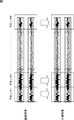
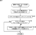
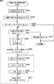
図1を参照して、ブロック処理について説明する。 Block processing will be described with reference to FIG.
ブロック処理においては、観測信号(ここでは、例えば、複数のマイクによって集音された音信号)を一定時間(例えば、1乃至3秒程度)のブロックに区切り、ブロックごとにバッチ処理が行なわれる。すなわち、1ブロック分の観測信号が入力されると、1ブロック分の観測信号に対して学習が実行され、1ブロック分の分離結果が出力されるようになされている。 In the block processing, the observation signal (here, for example, sound signals collected by a plurality of microphones) is divided into blocks of a predetermined time (for example, about 1 to 3 seconds), and batch processing is performed for each block. That is, when an observation signal for one block is input, learning is performed on the observation signal for one block, and a separation result for one block is output.
こうすることで、入力を中断することなく、連続的に分離結果を出力することが可能となる。しかしながら、ブロック処理においても、入力から出力までの遅延は発生してしまう。発生する遅延は、ブロックの長さと学習に要する時間との合計である。例えば、ブロック処理におけるブロックの長さを1秒、学習に要する時間を0.5秒とすると、入力に対する出力の遅延は1.5秒となる。 In this way, it is possible to output the separation results continuously without interrupting the input. However, a delay from input to output also occurs in block processing. The delay that occurs is the sum of the block length and the time required for learning. For example, if the block length in the block processing is 1 second and the time required for learning is 0.5 seconds, the output delay with respect to the input is 1.5 seconds.
このように、ブロック処理においては遅延時間が発生してしまうため、前のブロックで求めた分離行列を用いて分離を行なうことにより、遅延を少なくすることが提案されている(例えば、非特許文献2、または、非特許文献3参照)。 As described above, since delay time occurs in block processing, it has been proposed to reduce the delay by performing separation using the separation matrix obtained in the previous block (for example, non-patent literature). 2 or non-patent document 3).
前のブロックで求めた分離行列を用いて分離を行なうブロック処理を、以下、改良版ブロック処理と称するものとする。 Block processing that performs separation using the separation matrix obtained in the previous block is hereinafter referred to as improved block processing.
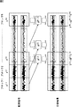
図2を参照して、改良版ブロック処理の概要について説明する。 With reference to FIG. 2, the outline of the improved block processing will be described.
改良版ブロック処理においても、観測信号を一定時間(例えば、1乃至3秒程度)のブロックに区切り、ブロックごとにバッチ処理が行なわれる。 Also in the improved block processing, the observation signal is divided into blocks of a fixed time (for example, about 1 to 3 seconds), and batch processing is performed for each block.
先頭からk番目のブロックX[k]に属する観測信号X(t)を分離する場合、その観測信号が入力された時点では、k番目のブロックX[k]に対応する分離行列W[k]は、もちろん、まだ求められていない。そこで、学習時間がブロック長よりも短ければ、X(t)が観測される時点でW[k-2]は既に求められていることを利用して、分離行列W[k]の代わりに、2つ前のブロックから学習された分離行列W[k-2]を用いて、分離結果Y=W×Xを演算するものとする。すなわち、改良版ブロック処理においては、ある時刻の観測信号X(t)を分離して分離結果Y(t)を求めるには、Y(t)=W[k-2]×X(t)が演算される。 When the observation signal X (t) belonging to the kth block X [k] from the top is separated, the separation matrix W [k] corresponding to the kth block X [k] is input when the observation signal is input . Is, of course, not yet sought after. So, if the learning time is shorter than the block length, using the fact that W [k-2] is already obtained when X (t) is observed, instead of the separation matrix W [k] , It is assumed that the separation result Y = W × X is calculated using the separation matrix W [k−2] learned from the previous block. That is, in the improved block processing, to separate the observation signal X (t) at a certain time and obtain the separation result Y (t), Y (t) = W [k-2] × X (t) Calculated.
これにより、入力を中断することなく、連続的に分離結果を出力することが可能となるとともに、少ない遅延で分離を行なうことができる。なお、分離処理、すなわち、Y(t)=W[k-2]×X(t)の演算に要する時間は、観測信号の蓄積や学習と比べて短い。ただし、厳密には、時間周波数領域のICAにおいては、ICAの前後に短時間フーリエ変換と逆変換とを必要とするため、改良版ブロック処理であっても、フーリエ変換のタップ数だけの遅延は生じる。 As a result, it is possible to output separation results continuously without interrupting input, and separation can be performed with a small delay. Note that the time required for the separation process, that is, the calculation of Y (t) = W [k−2] × X (t) is shorter than the accumulation and learning of observation signals. However, strictly speaking, ICA in the time-frequency domain requires short-time Fourier transform and inverse transform before and after ICA, so even with the improved block processing, the delay by the number of taps of Fourier transform Arise.
例えば、複数のマイクによって集音された音信号を、独立成分分析(independent component analysis: ICA)を用いて統計的に独立な成分へと分解する場合、その分離行列Wは、音源とマイクとの間の空間伝達特性を反映している。したがって、その伝達特性が変わらない場合、すなわち、音源もマイクも移動しない場合、改良版ブロック処理を行っても、すなわち、分離行列Wを求めるのに用いたブロックと分離行列Wを適用するブロックとが異なっていても、十分に分離された結果を得ることができる。 For example, when a sound signal collected by a plurality of microphones is decomposed into components that are statistically independent using independent component analysis (ICA), the separation matrix W is calculated as follows. It reflects the spatial transfer characteristics between the two. Therefore, when the transfer characteristic does not change, that is, when neither the sound source nor the microphone moves, even if the improved block processing is performed, that is, the block used to obtain the separation matrix W and the block to which the separation matrix W is applied Even if they are different, a sufficiently separated result can be obtained.
一方、マイクや音源が移動する場合は、分離行列の計算で用いたブロックX[k-2]と、分離行列を適用するブロックX[k]との間で空間伝達特性が変化してしまうため、分離行列W[k]の代わりに、2つ前のブロックから学習された分離行列W[k-2]を用いて得られる分離結果Y(t)=W[k-2]×X(t)は、追従遅れが生じることにより、完全な分離結果とはならない。すなわち、マイクや音源が移動する場合は、改良版ブロック処理を用いることにより精度のよい分離結果を得ることができなかった。 On the other hand, if the microphone or sound source is moving, a block X [k-2] used in the calculation of the separating matrix, for spatial transfer characteristics between the block X [k] applying the separating matrix is changed , instead of the separation matrix W [k], the separation results obtained by using the learned from two previous block the separation matrix W [k-2] Y ( t) = W [k-2] × X (t ) Is not a complete separation result due to the following delay. That is, when the microphone or the sound source moves, it is impossible to obtain an accurate separation result by using the improved block processing.
更に、改良版ブロック処理においては、分離性能と追従遅れとの間にはトレードオフが発生する。具体的には、音源やマイクが移動しない場合は、長い時間の観測信号を用いて学習した方が(すなわち、ブロックを長くした方が)、分離の性能が高くなる。一方、音源やマイクが移動する場合は、ブロックが長いと追従遅れが増大してしまう。 Further, in the improved block processing, a trade-off occurs between separation performance and follow-up delay. Specifically, when the sound source or the microphone does not move, the performance of separation is improved by learning using a long-time observation signal (that is, by increasing the length of the block). On the other hand, when the sound source or the microphone moves, the tracking delay increases if the block is long.
また、2つ前のブロックから求まった分離行列W[k-2]を利用するためには、W[k]の先頭の観測信号が入力された時点でW[k-2]が既に求まっている必要がある。すなわち、学習に要する時間がブロック長よりも短くなければならない。しかしながら、学習時間は一定とは限らない。また、例えば、マルチタスクOSを搭載したパーソナルコンピュータなどの情報処理装置において、上述した改良版ブロック処理を実行可能とした(実装した)場合、改良版ブロック処理だけを考慮したときに、学習に要する時間がブロック長よりも平均的に短かったとしても、学習処理中に、他のプロセスの影響で、一時的にプロセッサが高負荷となり、学習時間がブロック長を超えてしまう可能性がある。 In addition, in order to use the separation matrix W [k-2] obtained from the previous block, W [k-2] has already been obtained when the first observation signal of W [k] is input. Need to be. That is, the time required for learning must be shorter than the block length. However, the learning time is not always constant. Further, for example, in an information processing apparatus such as a personal computer equipped with a multitasking OS, when the improved block processing described above is executable (implemented), learning is required when only the improved block processing is considered. Even if the time is shorter than the block length on average, there is a possibility that the processor is temporarily heavily loaded due to the influence of other processes during the learning process, and the learning time may exceed the block length.
このように、学習に要する時間がブロック長よりも短くなることを保証することができない場合、上述した改良版ブロック処理では、正しい分離結果を得ることができなかった。 As described above, when the time required for learning cannot be guaranteed to be shorter than the block length, the above-described improved block processing cannot obtain a correct separation result.
すなわち、ICAを用いた音源分離システムで、リアルタイム処理を実行するにあたって、従来の技術においては、ブロック長と追従遅れとのトレードオフを解消することや、ブロック長と分離行列の更新間隔と学習時間とを自由に設定したいという要求があった。なお、ここでいうリアルタイム処理とは、連続的に入力される観測信号を、少ない遅延で独立な成分へと分解し、それを連続的に出力することである。 In other words, when executing real-time processing in a sound source separation system using ICA, the conventional technology eliminates the trade-off between block length and tracking delay, updates the block length and separation matrix update interval, and learning time. There was a request to set up freely. Note that the real-time processing here means that an observation signal that is continuously input is decomposed into independent components with a small delay and is output continuously.
本発明はこのような状況に鑑みてなされたものであり、独立成分分析(independent component analysis: ICA)を用いて、リアルタイムに音源分離を行なう場合に、少ない遅延で独立な成分へと分解し、それを連続的に出力することができるようにするものである。 The present invention has been made in view of such a situation, and when performing sound source separation in real time using independent component analysis (ICA), it is decomposed into independent components with a small delay, It makes it possible to output it continuously.
本発明の一側面の情報処理装置は、独立成分分析を実行する情報処理装置であって、信号を取得する取得手段と、前記取得手段により取得された前記信号を用いて、前記独立成分分析の学習によって分離行列を求める学習手段と、前記取得手段により取得された前記信号に、前記学習手段により求められた前記分離行列を適用することによって、分離結果を生成する分離手段とを備え、前記学習手段は、前記信号を蓄積する第1の状態と蓄積された前記信号を用いて前記独立成分分析に基づくバッチ処理を実行することにより前記分離行列を演算する第2の状態の少なくとも2つの状態を有し、前記分離行列を学習により求める複数の演算手段と、複数の前記演算手段を制御する演算制御手段とを備え、前記演算手段は、前記第1の状態および前記第2の状態のいずれの状態でもなく、処理を待機する第3の状態を更に有し、前記演算制御手段は、前記演算手段における前記第3の状態の時間を制御することにより、複数の前記演算手段のそれぞれにおける前記第1の状態の開始タイミングが、前記分離行列の学習を行う単位期間であるブロック長よりも短い期間で略均等にずれるように、複数の前記演算手段を制御する。 An information processing apparatus according to an aspect of the present invention is an information processing apparatus that performs independent component analysis, and uses an acquisition unit that acquires a signal and the signal acquired by the acquisition unit to perform the independent component analysis. Learning means for obtaining a separation matrix by learning; and separation means for generating a separation result by applying the separation matrix obtained by the learning means to the signal obtained by the obtaining means; The means includes at least two states of a first state in which the signal is accumulated and a second state in which the separation matrix is calculated by executing batch processing based on the independent component analysis using the accumulated signal. a, comprising a plurality of arithmetic means for obtaining by learning the separating matrix, and an arithmetic control unit for controlling a plurality of said calculation means, said calculation means, said first state Oyo Nor any state of the second state, further comprising a third state of waiting for processing, the arithmetic control unit controls the time of the third state in the operation means, a plurality of The plurality of calculation means are controlled so that the start timing of the first state in each of the calculation means is substantially evenly shifted in a period shorter than the block length, which is a unit period for learning the separation matrix.
前記演算制御手段には、前記第1の状態および前記第2の状態の少なくとも一部のタイミングが、複数の前記演算手段のいずれかにおいて重複するように、複数の前記演算手段を制御させるようにすることができる。これにより、例えば、従来のブロック処理が有していた、音源分離性能と音源追従性能とのトレードオフを解消することができる。 The calculation control means controls a plurality of the calculation means so that timings of at least a part of the first state and the second state overlap in any of the plurality of calculation means. can do. Thereby, for example, the trade-off between the sound source separation performance and the sound source tracking performance, which the conventional block processing has, can be solved.
前記演算手段は、前記第1の状態および前記第2の状態のいずれの状態でもなく、処理を待機する第3の状態を更に有するものとすることができ、前記演算制御手段には、前記演算手段における前記第3の状態の時間を制御することにより、複数の前記演算手段のそれぞれにおける前記第1の状態の開始タイミングがずれるように、複数の前記演算手段を制御させるようにすることができる。 The calculation means may further include a third state that waits for processing, not the first state or the second state, and the calculation control means includes the calculation state. By controlling the time of the third state in the means, the plurality of computing means can be controlled so that the start timing of the first state in each of the plurality of computing means is shifted. .
前記演算制御手段には、前記演算手段における前記第3の状態の時間を制御することにより、複数の前記演算手段のそれぞれにおける前記第1の状態の開始タイミングが、略均等にずれるように、複数の前記演算手段を制御させるようにすることができる。 The arithmetic control means includes a plurality of control units that control the time of the third state in the arithmetic means so that the start timing of the first state in each of the plurality of arithmetic means is substantially evenly shifted. The calculation means can be controlled.
前記演算制御手段には、前記演算手段における前記第3の状態の時間を制御することにより、前記第1の状態および前記第2の状態の少なくとも一部のタイミングが、複数の前記演算手段のいずれかにおいて重複するように、複数の前記演算手段を制御させるようにすることができる。 The arithmetic control means controls the time of the third state in the arithmetic means so that at least a part of the timings of the first state and the second state can be any of the plurality of arithmetic means. A plurality of the arithmetic means can be controlled so as to overlap each other.
前記演算手段において、前記第1の状態は、所定の一定期間継続されるものとすることができ、前記演算制御手段には、前記演算手段のいずれかにおいて前記第1の状態が開始するタイミングの間隔が、前記第1の状態が継続される前記所定の一定期間よりも短くなるように、複数の前記演算手段を制御させるようにすることができる。 In the calculation means, the first state can be continued for a predetermined fixed period, and the calculation control means has a timing at which the first state starts in any of the calculation means. A plurality of the calculation means can be controlled such that the interval is shorter than the predetermined period during which the first state is continued.
前記演算制御手段には、複数の前記演算手段のうちのいずれかの前記演算手段が前記独立成分分析に基づくバッチ処理を実行することにより前記分離行列を算出した場合、算出された前記分離行列を求めるために用いた前記第1の状態において蓄積された前記信号の蓄積区間は、他の前記演算手段が既に算出した前記分離行列を求めるために用いた前記信号の蓄積区間よりも新しいか否かを判断し、新しくないと判断された場合、算出された前記分離行列を破棄させるようにすることができる。 In the calculation control unit, when the calculation unit of any of the plurality of calculation units calculates the separation matrix by executing batch processing based on the independent component analysis, the calculated separation matrix is Whether the signal accumulation interval accumulated in the first state used for obtaining is newer than the signal accumulation interval used for obtaining the separation matrix already calculated by the other arithmetic means. If it is determined that it is not new, the calculated separation matrix can be discarded.
前記演算制御手段には、複数の前記演算手段のうちのいずれかの前記演算手段が前記独立成分分析に基づくバッチ処理を実行することにより前記分離行列を算出した場合、算出された前記分離行列を求めるために用いた前記第1の状態において蓄積された前記信号の蓄積区間よりも早い区間で蓄積した前記信号を用いて実行されている他の前記演算手段によるバッチ処理が中止されるように、他の前記演算手段を制御させるようにすることができる。 In the calculation control unit, when the calculation unit of any of the plurality of calculation units calculates the separation matrix by executing batch processing based on the independent component analysis, the calculated separation matrix is So that the batch processing by the other arithmetic means being executed using the signal accumulated in the section earlier than the accumulation period of the signal accumulated in the first state used for obtaining is canceled, The other calculation means can be controlled.
前記演算制御手段には、前記演算手段が前記分離行列を求める学習に用いる分離行列の初期値として、複数の前記演算手段のいずれかにおいて最も新しく求められた前記分離行列が用いられるように、複数の前記演算手段を制御させるようにすることができる。 The arithmetic control means includes a plurality of the separation matrices that are most recently obtained in any of the plurality of arithmetic means as the initial value of the separation matrix used for learning that the arithmetic means obtains the separation matrix. The calculation means can be controlled.
前記演算制御手段には、前記演算手段が前記分離行列を求める学習に用いる分離行列の初期値として、複数の前記演算手段のいずれかにおいて最も新しく求められた前記分離行列とそれ以前に求められた過去の学習による分離行列とを用いて演算されて得られた値が用いられるように、複数の前記演算手段を制御させるようにすることができる。 In the arithmetic control means, as the initial value of the separation matrix used for learning in which the arithmetic means obtains the separation matrix, the separation matrix obtained most recently in any of the plurality of arithmetic means and previously obtained A plurality of the calculation means can be controlled so that values obtained by calculation using a separation matrix obtained by past learning are used.
前記演算制御手段には、複数の前記演算手段が前記第1の状態において同一の信号保持手段に前記信号を保持し、前記第2の状態において、前記信号保持手段により保持されている前記信号を用いるように、複数の前記演算手段を制御させるようにすることができる。このことは、例えば、複数の演算手段が信号保持手段を共有すると換言することができる。 In the calculation control means, the plurality of calculation means hold the signal in the same signal holding means in the first state, and the signal held by the signal holding means in the second state. As used, a plurality of the calculating means can be controlled. This can be said, for example, that a plurality of calculation means share the signal holding means.
前記演算手段には、前記第1の状態において前記取得手段により取得された前記信号のうちの一部を用いて、前記信号処理手段による独立成分分析に用いられる前記分離行列を学習により求めさせるようにすることができる。 The computing means is caused to obtain the separation matrix used for independent component analysis by the signal processing means by learning using a part of the signals obtained by the obtaining means in the first state. Can be.
本発明の一側面の情報処理方法は、独立成分分析を実行する情報処理装置の情報処理方法であって、信号を取得し、取得された前記信号を蓄積する第1の状態と蓄積された前記信号を用いて前記独立成分分析に基づくバッチ処理を実行することにより前記分離行列を演算する第2の状態の少なくとも2つの状態を有し、前記分離行列を学習により求める複数の演算部において、分離処理に用いられる分離行列を学習により求める処理を制御し、取得された前記信号に前記分離行列を適用することによって、分離結果を生成するステップを含み、前記演算部は、前記第1の状態および前記第2の状態のいずれの状態でもなく、処理を待機する第3の状態を更に有し、前記演算部における前記第3の状態の時間を制御することにより、複数の前記演算部のそれぞれにおける前記第1の状態の開始タイミングが、前記分離行列の学習を行う単位期間であるブロック長よりも短い期間で略均等にずれるように、複数の前記演算部による前記学習の処理が制御される。 An information processing method according to an aspect of the present invention is an information processing method for an information processing apparatus that performs independent component analysis, and acquires a signal, stores the acquired signal, and the stored first state. In a plurality of calculation units having at least two states of a second state in which the separation matrix is calculated by performing batch processing based on the independent component analysis using a signal, and obtaining the separation matrix by learning Controlling a process for obtaining a separation matrix to be used for processing by learning, and applying the separation matrix to the acquired signal to generate a separation result, wherein the computing unit includes the first state and nor any state of the second state, further comprising a third state of waiting for processing, by controlling the time of the third state in the operation portion, a plurality of the Start timing of the first state in each of the calculation unit, said to be shifted substantially uniformly in a shorter period of time than the block length which is a unit period for learning of the separating matrix, the process of the learning by the plurality of the arithmetic unit Is controlled.
本発明の一側面のプログラムは、独立成分分析を実行する処理をコンピュータに実行させるためのプログラムであって、信号の取得を制御し、取得が制御された前記信号を蓄積する第1の状態と蓄積された前記信号を用いて前記独立成分分析に基づくバッチ処理を実行することにより前記分離行列を演算する第2の状態の少なくとも2つの状態を有し、前記分離行列を学習により求める複数の演算部において、分離処理に用いられる分離行列を学習により求める処理を制御し、取得された前記信号に前記分離行列を適用することによって、分離結果を生成するステップを含み、前記演算部は、前記第1の状態および前記第2の状態のいずれの状態でもなく、処理を待機する第3の状態を更に有し、前記演算部における前記第3の状態の時間を制御することにより、複数の前記演算部のそれぞれにおける前記第1の状態の開始タイミングが、前記分離行列の学習を行う単位期間であるブロック長よりも短い期間で略均等にずれるように、複数の前記演算部による前記学習の処理が制御される処理をコンピュータに実行させる。
A program according to one aspect of the present invention is a program for causing a computer to execute a process of performing independent component analysis, the first state of controlling acquisition of a signal and storing the signal of which acquisition is controlled. A plurality of operations that have at least two states of a second state in which the separation matrix is calculated by executing batch processing based on the independent component analysis using the accumulated signal and that obtain the separation matrix by learning And a step of generating a separation result by controlling a process for obtaining a separation matrix used for the separation process by learning and applying the separation matrix to the acquired signal . It is not in any of the
本発明の一側面においては、信号が取得され、取得された信号を蓄積する第1の状態と蓄積された信号を用いて独立成分分析に基づくバッチ処理を実行することにより分離行列を演算する第2の状態の少なくとも2つの状態を有し、分離行列を学習により求める複数の演算部が用いられて、分離処理に用いられる分離行列が学習により求められ、取得された信号に分離行列が適用されることによって、分離結果が生成される。そして、演算部は、第1の状態および第2の状態のいずれの状態でもなく、処理を待機する第3の状態を更に有し、演算部における第3の状態の時間が制御されることにより、複数の演算部のそれぞれにおける第1の状態の開始タイミングが、分離行列の学習を行う単位期間であるブロック長よりも短い期間で略均等にずれるように複数の演算部による学習が制御される。 In one aspect of the present invention, a signal is acquired, and a first state in which the acquired signal is stored and a batch process based on independent component analysis is performed using the stored signal to calculate a separation matrix. A plurality of arithmetic units that have at least two states of 2 and obtain a separation matrix by learning are used, a separation matrix used for separation processing is obtained by learning, and the separation matrix is applied to the acquired signal. As a result, a separation result is generated. The computing unit is not in either the first state or the second state, but has a third state waiting for processing, and the time of the third state in the computing unit is controlled. , the start timing of the first state in each of the plurality of operation portions, learning is controlled by a plurality of operation portions so as to be offset substantially uniformly in a shorter period of time than the block length which is a unit period for learning of the separating matrix .
音源分離装置は、独立した装置であっても良いし、情報処理装置の音源分離処理を行なうブロックであっても良い。 The sound source separation device may be an independent device or a block that performs sound source separation processing of the information processing device.
本発明の一側面によれば、独立成分分析を行なうことができ、特に、学習処理を複数のスレッドで並列して行なうようにして、各スレッドの状態遷移のタイミングをずらすようにしたので、精度よく独立成分分析を行なうことができるとともに、少ない遅延で独立な成分へと分解し、それを連続的に出力することができる。 According to one aspect of the present invention, independent component analysis can be performed, and in particular, the learning process is performed in parallel with a plurality of threads, and the timing of the state transition of each thread is shifted. Independent component analysis can be performed well, and it can be decomposed into independent components with a small delay and output continuously.
以下に本発明の実施の形態を説明するが、本発明の構成要件と、明細書または図面に記載の実施の形態との対応関係を例示すると、次のようになる。この記載は、本発明をサポートする実施の形態が、明細書または図面に記載されていることを確認するためのものである。従って、明細書または図面中には記載されているが、本発明の構成要件に対応する実施の形態として、ここには記載されていない実施の形態があったとしても、そのことは、その実施の形態が、その構成要件に対応するものではないことを意味するものではない。逆に、実施の形態が構成要件に対応するものとしてここに記載されていたとしても、そのことは、その実施の形態が、その構成要件以外の構成要件には対応しないものであることを意味するものでもない。 Embodiments of the present invention will be described below. Correspondences between constituent elements of the present invention and the embodiments described in the specification or the drawings are exemplified as follows. This description is intended to confirm that the embodiments supporting the present invention are described in the specification or the drawings. Therefore, even if there is an embodiment which is described in the specification or the drawings but is not described here as an embodiment corresponding to the constituent elements of the present invention, that is not the case. It does not mean that the form does not correspond to the constituent requirements. Conversely, even if an embodiment is described here as corresponding to a configuration requirement, that means that the embodiment does not correspond to a configuration requirement other than the configuration requirement. It's not something to do.
本発明の一側面の情報処理装置は、独立成分分析を実行する情報処理装置であって、信号を取得する取得手段(例えば、音信号取得部29)と、前記取得手段により取得された前記信号を用いて、前記独立成分分析の学習によって分離行列を求める学習手段(例えば、図8のバックグラウンド処理部72)と、前記取得手段により取得された前記信号に、前記学習手段により求められた前記分離行列を適用することによって、分離結果を生成する分離手段(たとえば、図8の信号処理部71)とを備え、前記学習手段は、前記信号を蓄積する第1の状態(例えば、「蓄積中」状態)と蓄積された前記信号を用いて前記独立成分分析に基づくバッチ処理を実行することにより前記分離行列を演算する第2の状態(例えば、「学習中」状態)の少なくとも2つの状態を有し、前記分離行列を学習により求める複数の演算手段(例えば、図8のスレッド101−1乃至101−N)と、複数の前記演算手段を制御する演算制御手段(例えば、図8のスレッド制御部91)とを備え、前記演算手段は、前記第1の状態および前記第2の状態のいずれの状態でもなく、処理を待機する第3の状態(例えば、「待機中」状態)を更に有することができ、前記演算制御手段は、前記演算手段における前記第3の状態の時間を制御することにより、複数の前記演算手段のそれぞれにおける前記第1の状態の開始タイミングが、前記分離行列の学習を行う単位期間であるブロック長よりも短い期間で略均等にずれるように、複数の前記演算手段を制御する。 An information processing apparatus according to an aspect of the present invention is an information processing apparatus that performs independent component analysis, and includes an acquisition unit that acquires a signal (for example, a sound signal acquisition unit 29) and the signal acquired by the acquisition unit. And learning means (for example, the background processing unit 72 in FIG. 8) for obtaining a separation matrix by learning of the independent component analysis, and the signal obtained by the obtaining means to the signal obtained by the learning means. A separation unit that generates a separation result by applying a separation matrix (for example, the signal processing unit 71 in FIG. 8), and the learning unit stores a first state (for example, “accumulating in progress”). ”State) and a second state (for example,“ learning ”state) in which the separation matrix is calculated by executing batch processing based on the independent component analysis using the accumulated signal. A plurality of arithmetic means (for example, threads 101-1 to 101-N in FIG. 8) having at least two states and obtaining the separation matrix by learning, and an arithmetic control means (for example, controlling the plurality of arithmetic means) , And the calculation means is in either of the first state and the second state, and is in a third state (for example, “waiting”). ”State), and the calculation control unit controls the time of the third state in the calculation unit, so that the start timing of the first state in each of the plurality of calculation units is The plurality of arithmetic means are controlled so as to be substantially evenly shifted in a period shorter than the block length which is a unit period for learning the separation matrix.
前記演算制御手段は、前記演算手段が前記分離行列を求める学習に用いる分離行列の初期値として、複数の前記演算手段のいずれかにおいて最も新しく求められた前記分離行列とそれ以前に求められた過去の学習による分離行列とを用いて演算されて得られた値(例えば、W_init=(W[k]+W[k-1] +・・・+W[k-N])/(N+1)またはaW+(1-a)W_initなどであり、ここで、W[k]は、システムが起動されてからk番目に求められた分離行列である)が用いられるように、複数の前記演算手段を制御することができる。 The arithmetic control unit is configured such that the arithmetic unit is used as an initial value of a separation matrix used for learning to obtain the separation matrix, and the separation matrix most recently obtained in any of the plurality of arithmetic units and a past obtained previously. And a value obtained by calculation using a separation matrix obtained by learning (for example, W_init = (W [k] + W [k-1] +... + W [kN] ) / (N + 1) or aW + (1− a) W_init, where W [k] is a k-th separation matrix obtained after the system is started), and the plurality of arithmetic means can be controlled. .
本発明の一側面の情報処理方法は、独立成分分析を実行する情報処理装置の情報処理方法であって、信号を取得し(例えば、図12のステップS2の処理)、取得された前記信号を蓄積する第1の状態(例えば、「蓄積中」状態)と蓄積された前記信号を用いて前記独立成分分析に基づくバッチ処理を実行することにより前記分離行列を演算する第2の状態(例えば、「学習中」状態)の少なくとも2つの状態を有し、前記分離行列を学習により求める複数の演算部(例えば、図8のスレッド101−1乃至101−N)において、分離処理に用いられる分離行列を学習により求める処理を制御し(例えば、図12のステップS4の処理)、取得された前記信号に前記分離行列を適用することによって、分離結果を生成する(例えば、図12のステップS5の処理)ステップを含み、前記演算部は、前記第1の状態および前記第2の状態のいずれの状態でもなく、処理を待機する第3の状態(例えば、「待機中」状態)を更に有することができ、前記演算部における前記第3の状態の時間を制御することにより、複数の前記演算部のそれぞれにおける前記第1の状態の開始タイミングが、前記分離行列の学習を行う単位期間であるブロック長よりも短い期間で略均等にずれるように、複数の前記演算部による前記学習の処理が制御される。 An information processing method according to one aspect of the present invention is an information processing method of an information processing apparatus that performs independent component analysis, acquires a signal (for example, the process of step S2 in FIG. 12), and uses the acquired signal. A second state (e.g., computing the separation matrix by performing a batch process based on the independent component analysis using the accumulated first state (e.g., "accumulating" state) and the accumulated signal (e.g., A separation matrix used for separation processing in a plurality of arithmetic units (for example, threads 101-1 to 101-N in FIG. 8) that have at least two states of “learning” state and obtain the separation matrix by learning. Is controlled by learning (for example, the process of step S4 in FIG. 12), and the separation matrix is applied to the acquired signal to generate a separation result (for example, FIG. 12). Processing in step S5) includes the step, the arithmetic unit is not in any state of the first state and the second state, a third state of waiting for processing (e.g., the "waiting" state) A unit period in which the start timing of the first state in each of the plurality of computing units learns the separation matrix by controlling the time of the third state in the computing unit. The learning process by the plurality of arithmetic units is controlled so as to be substantially evenly shifted in a period shorter than the block length.
本発明の一側面のプログラムは、独立成分分析を実行する処理をコンピュータに実行させるためのプログラムであって、信号の取得を制御し(例えば、図12のステップS2の処理)、取得が制御された前記信号を蓄積する第1の状態(例えば、「蓄積中」状態)と蓄積された前記信号を用いて前記独立成分分析に基づくバッチ処理を実行することにより前記分離行列を演算する第2の状態(例えば、「学習中」状態)の少なくとも2つの状態を有し、前記分離行列を学習により求める複数の演算部(例えば、図8のスレッド101−1乃至101−N)において、分離処理に用いられる分離行列を学習により求める処理を制御し(例えば、図12のステップS4の処理)、取得された前記信号に前記分離行列を適用することによって、分離結果を生成する(例えば、図12のステップS5の処理)ステップを含み、前記演算部は、前記第1の状態および前記第2の状態のいずれの状態でもなく、処理を待機する第3の状態(例えば、「待機中」状態)を更に有することができ、前記演算部における前記第3の状態の時間を制御することにより、複数の前記演算部のそれぞれにおける前記第1の状態の開始タイミングが、前記分離行列の学習を行う単位期間であるブロック長よりも短い期間で略均等にずれるように、複数の前記演算部による前記学習の処理が制御される処理をコンピュータに実行させる。 A program according to one aspect of the present invention is a program for causing a computer to execute processing for executing independent component analysis, and controls acquisition of signals (for example, processing in step S2 in FIG. 12), and acquisition is controlled. A second state in which the separation matrix is calculated by executing batch processing based on the independent component analysis using the first state in which the signal is accumulated (for example, the “accumulating” state) and the accumulated signal. In a plurality of arithmetic units (for example, threads 101-1 to 101-N in FIG. 8) having at least two states (for example, “learning” state) and obtaining the separation matrix by learning, separation processing is performed. Control processing for obtaining a separation matrix to be used by learning (for example, processing in step S4 of FIG. 12), and applying the separation matrix to the acquired signal Generating a result (for example, step S5 in FIG. 12) includes the step, the arithmetic unit is not in any state of the first state and the second state, a third state of waiting for processing (For example, a “standby” state), and by controlling the time of the third state in the arithmetic unit, the start timing of the first state in each of the arithmetic units is , Causing the computer to execute a process for controlling the learning process by the plurality of arithmetic units so as to shift substantially evenly in a period shorter than a block length that is a unit period for learning the separation matrix.
以下、図を参照して、本発明の実施の形態について説明する。 Hereinafter, embodiments of the present invention will be described with reference to the drawings.
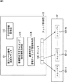
図3に、音源分離装置11のブロック図を示す。
FIG. 3 shows a block diagram of the sound
CPU(Central Processing Unit)21−1乃至21−Pは、マルチプロセッサであり、ROM(Read Only Memory)22に記憶されているプログラム、または記憶部28からRAM(Random Access Memory)23にロードされたプログラムにしたがって、各種の処理を実行する。RAM23にはまた、CPU21が各種の処理を実行する上において必要なデータなども適宜記憶される。
CPUs (Central Processing Units) 21-1 to 21 -P are multiprocessors, and are loaded from a program stored in a ROM (Read Only Memory) 22 or a RAM (Random Access Memory) 23 from a
CPU21、ROM22、およびRAM23は、バス24を介して相互に接続されている。このバス24にはまた、入出力インタフェース24も接続されている。
The
入出力インタフェース24には、キーボード、マウスなどよりなる入力部26、ディスプレイやスピーカなどよりなる出力部27、ハードディスクなどより構成される記憶部28、および、音信号を取得する音信号取得部29が接続されている。音信号取得部29は、例えば、複数のマイクロホンおよびAD変換部を含んで構成され、複数のマイクロホンによって集音された音信号を、AD変換部の処理によりデジタル信号に変換する。
The input /
入出力インタフェース24にはまた、必要に応じてドライブ30が接続され、磁気ディスク31、光ディスク32、光磁気ディスク33、もしくは、半導体メモリ34などが適宜装着され、それらから読み出されたコンピュータプログラムが、必要に応じて記憶部28にインストールされる。
A drive 30 is connected to the input /
CPU21は、音信号取得部29により取得された、複数のマイクによって集音され、デジタル信号に変換された音信号に対して、独立成分分析(independent component analysis: ICA)を実行するものである。
The
CPU21は、ICAを実行するにあたって、スレッドと称する処理の単位を用いて、逐次処理、すなわち、略リアルタイムで観測信号から分離信号を出力する処理を可能とするものである。
When executing the ICA, the
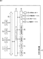
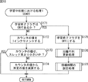
CPU21は、複数のスレッドを並行して動作させる。それぞれのスレッドは、少なくとも、観測信号の蓄積、および、分離行列の学習の2つの状態を有し、必要に応じて、待機の状態を取ることも可能である。スレッドは、これらの状態間の遷移を繰り返す。
The
観測信号の蓄積中の状態において、スレッドは、一定時間の観測信号を蓄積する。この一定時間を、以下、1ブロック長と称するものとする。 In a state where the observation signal is being accumulated, the thread accumulates the observation signal for a certain time. This fixed time is hereinafter referred to as one block length.
分離行列の学習中の状態において、スレッドは、蓄積した観測信号から分離行列を求める学習処理を実行する。 In the state where the separation matrix is being learned, the thread executes a learning process for obtaining the separation matrix from the accumulated observation signals.
待機中の状態において、スレッドは、観測信号の蓄積や学習処理を実行せずに、待機する。 In the waiting state, the thread waits without executing observation signal accumulation or learning processing.
CPU21においては、複数のスレッドが時刻をずらして起動される。また、ブロック長、分離行列の更新間隔、学習時間の最大値などは、それぞれ、設定可能なようになされている。
In the
そして、ブロック長よりも短い間隔で異なるスレッドを起動する、換言すれば、複数のスレッドのそれぞれにおいて、上述した3つの状態の遷移タイミングを調整して所定時間だけずらすことにより、ブロック長よりも短い間隔で分離行列Wを更新できるようになり、ブロック長と追従遅れとのトレードオフを解消することが可能となる。 Then, different threads are activated at intervals shorter than the block length, in other words, each of the plurality of threads is shorter than the block length by adjusting the transition timings of the three states described above and shifting them by a predetermined time. The separation matrix W can be updated at intervals, and the trade-off between block length and tracking delay can be eliminated.
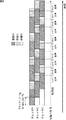
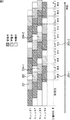
例えば、図4を用いて、複数のスレッドを並行して起動する場合の一例として、3つのスレッドが並行して起動されたときの状態遷移について説明する。 For example, with reference to FIG. 4, state transition when three threads are started in parallel will be described as an example of starting a plurality of threads in parallel.
スレッド1乃至スレッド3のそれぞれでは、観測信号の「蓄積中」状態において、指定された時間、すなわち1ブロック長の観測信号がバッファに蓄えられる。指定された時間が経過した後、状態は、学習中に遷移する。
In each of the
学習中の状態において、分離行列Wが収束するまで(または一定回数)学習処理ループが実行され、蓄積中の状態において蓄積された観測信号に対応した分離行列が求められる。分離行列Wが収束した後(または一定回数の学習処理ループが実行された後)状態は、待機中に遷移する。 In the learning state, a learning process loop is executed until the separation matrix W converges (or a fixed number of times), and a separation matrix corresponding to the observation signal accumulated in the accumulation state is obtained. After the separation matrix W converges (or after a certain number of learning processing loops have been executed), the state transitions to waiting.
そして、待機中の状態において、指定された時間だけ、観測信号の蓄積や学習は実行されず、待機される。待機中の状態を維持する時間は、学習にかかった時間によって決まる。すなわち、図5に示されるように、予め、「蓄積中」状態と「学習中」状態と「待機中」状態との合計の時間幅であるスレッド長(thread_len)が定められ、基本的には、「学習中」状態が終了したときからスレッド長が終了するまでの間の時間が、「待機中」状態の時間(待機時間)とされる。待機時間が過ぎた後、状態は、観測信号の「蓄積中」状態へ戻る。 Then, in the standby state, the observation signal is not accumulated or learned for a specified time, and the standby is performed. The time for maintaining the waiting state is determined by the time taken for learning. That is, as shown in FIG. 5, a thread length (thread_len) that is a total time width of the “accumulating” state, the “learning” state, and the “waiting” state is determined in advance. The time from the end of the “learning” state to the end of the thread length is the time in the “standby” state (standby time). After the waiting time has passed, the state returns to the “accumulating” state of the observation signal.
これらの時間は、例えば、ミリ秒などの単位で管理してもよいが、短時間フーリエ変換で生成されるフレームを単位として計測するものとしても良い。以降の説明では、フレームを単位として計測する(たとえば、カウントアップをおこなう)ものとする。 These times may be managed in units of milliseconds, for example, but may be measured in units of frames generated by short-time Fourier transform. In the following description, it is assumed that measurement is performed in units of frames (for example, counting up is performed).
そして、スレッド1乃至スレッド3のそれぞれは、所定のブロックシフト幅(Block_shift)だけずらして起動される。例えば、図4の場合においては、ブロック長の半分をブロックシフト幅としている。
Each of the
スレッド1の「学習中」状態が終了した後、スレッド1により得られた学習結果、すなわち、スレッド1由来の分離行列W[1]を用いて、それぞれのスレッドは処理を実行することができる。そして、スレッド2の「学習中」状態が終了した後、スレッド1により得られた学習結果よりも新しい、スレッド2により得られた学習結果、すなわち、スレッド2由来の分離行列W[2]を用いてそれぞれのスレッドは処理を実行することができる。
After the “learning” state of the
以下同様に、所定のブロックシフト幅(Block_shift)だけずらして起動されるそれぞれのスレッド由来の最新の分離行列Wを用いて、それぞれのスレッドは処理を実行することが可能なようになされている。すなわち、ブロック長よりも短い間隔で分離行列Wを更新することができるので、ブロック長と更新間隔とのトレードオフを回避することができる。 Similarly, each thread is configured to be able to execute processing using the latest separation matrix W derived from each thread that is activated while being shifted by a predetermined block shift width (Block_shift). That is, since the separation matrix W can be updated at an interval shorter than the block length, a trade-off between the block length and the update interval can be avoided.
また、学習時間がブロック長よりも長くなる可能性がある場合でも、その分だけ多くのスレッドを起動すれば、ブロック長や学習時間よりも短い間隔で分離行列Wを更新することができる。換言すれば、分離行列Wの更新頻度、すなわち追従遅れの度合いを、ブロック長や学習時間とは独立して設定することが可能になる。 Even if the learning time may be longer than the block length, the separation matrix W can be updated at an interval shorter than the block length and the learning time if more threads are activated accordingly. In other words, the update frequency of the separation matrix W, that is, the degree of follow-up delay can be set independently of the block length and the learning time.
また、学習時間が(スレッド長−ブロック長)よりも長くなってしまった場合、「学習中」状態の終了後、「待機中」状態に遷移せず、「蓄積中」状態に遷移するものとしても良い。 In addition, when the learning time becomes longer than (thread length−block length), after the “learning” state ends, the state does not transition to the “waiting” state, but transitions to the “accumulating” state. Also good.
これらの状態遷移を管理するために、それぞれのスレッドごとに、カウンタを用いて、「蓄積中」状態の開始からカウントアップを始める。上述したように、「蓄積中」状態はブロック長(block_len)の間継続され、カウンタ値がブロック長(block_len)となったとき、状態は、「学習中」状態に遷移する。そして、「学習中」状態が終了してから、カウンタ値がスレッド長(thread_len)となるまでの間が、「待機中」状態となるのであるが、「学習中」状態が終了したとき、カウンタ値がスレッド長(thread_len)と等しいか、それよりも大きい場合、状態は、「学習中」状態の終了後、「待機中」状態に遷移せず、「蓄積中」状態に遷移するものとする。 In order to manage these state transitions, for each thread, a counter is used to start counting up from the start of the “accumulating” state. As described above, the “accumulating” state continues for the block length (block_len), and when the counter value reaches the block length (block_len), the state transitions to the “learning” state. Then, after the “learning” state ends, the counter value becomes the thread length (thread_len) until the “waiting” state is reached, but when the “learning” state ends, the counter If the value is equal to or greater than the thread length (thread_len), the state shall transition to the “Accumulating” state instead of the “Waiting” state after the “Learning” state ends. .
すなわち、図6の状態遷移図に示されるように、システムの起動直後、各スレッドは「初期状態」にあるが、その内の1つが「蓄積中」状態となり、残りの全てのスレッドが「待機中」へ状態を遷移させる。すなわち、図4における場合では、スレッド1が、初期状態の後「蓄積中」へ遷移したスレッドであり、それ以外のスレッドが「初期状態」から「待機中」へ遷移したスレッドである。
That is, as shown in the state transition diagram of FIG. 6, immediately after the system is started, each thread is in the “initial state”, but one of them is in the “accumulating” state, and all the remaining threads are in the “waiting state”. Transition state to “medium”. That is, in the case of FIG. 4, the
「初期状態」から「待機中」へ遷移したスレッドにおける、最初の「待機中」から「蓄積中」への状態遷移について、「初期状態」から「待機中」へ状態が遷移したときのカウンタの値を、ブロックのシフト幅(block_shift)とスレッド長(thread_len)によって決まる所定の値とすることにより、「待機中」から「蓄積中」への状態の遷移の条件判断を、他と同様に実行可能なようにすることができる。 For the state transition from the first “waiting” to “accumulating” in the thread that has transitioned from “initial state” to “waiting”, the counter of the counter when the state transitions from “initial state” to “waiting” By setting the value to a predetermined value determined by the block shift width (block_shift) and thread length (thread_len), the condition judgment for the state transition from "Waiting" to "Accumulating" is executed in the same way as other Can be made possible.
すなわち、図4におけるスレッド2およびスレッド3において、例えば、「初期状態」から最初の「待機中」に状態が遷移されたとき、スレッド2の状態遷移を管理するためのカウンタの値をthread_len−block_shiftに設定し、スレッド3の状態遷移を管理するためのカウンタの値を、thread_len−block_shift×2に設定する。そして、スレッド1において蓄積されている観測信号のフレームと連動して、それぞれのカウンタの値をインクリメントする。このようにすれば、それぞれのカウンタの値がthread_lenに達したとき、状態を「待機中」から「蓄積中」へ遷移すればよいので、他の「待機中」から「蓄積中」への状態の遷移と同様の条件で、状態遷移を制御することが可能となる。
That is, in the
「蓄積中」から「学習中」への状態の遷移、および、「待機中」または「学習中」から「蓄積中」への状態遷移については、カウンタの値に基づいて行なわれる。すなわち、それぞれのスレッドにおいて、「蓄積中」の開始時にカウンタの値は初期化(例えば、0にセット)され、観測信号が1フレーム分供給されるごとにカウンタの値が1インクリメントされ、カウンタの値がblock_lenと同じ値になったら、「学習中」へ状態が遷移される。 The state transition from “accumulating” to “learning” and the state transition from “standby” or “learning” to “accumulating” are performed based on the value of the counter. That is, in each thread, the counter value is initialized (for example, set to 0) at the start of “accumulating”, and the counter value is incremented by 1 each time one observation signal is supplied. When the value becomes the same value as block_len, the state transitions to “learning”.
学習は、分離処理と並列にバックグラウンドで行なわれるが、その間も観測信号のフレームと連動してカウンタの値はインクリメントされる。 Learning is performed in the background in parallel with the separation processing, but during this time, the counter value is incremented in conjunction with the frame of the observation signal.
学習が終了した時、カウンタの値がthread_lenと比較される。カウンタの値がthread_lenより小さい場合、状態が「待機中」へ遷移される。待機中も学習中と同様に、観測信号のフレームと連動してカウンタがインクリメントされる。そして、待機中のカウンタ値がthread_lenと等しくなったとき、状態は、「蓄積中」に遷移され、観測信号の蓄積が開始されて、カウンタ値は初期化される。 When learning is finished, the counter value is compared with thread_len. When the value of the counter is smaller than thread_len, the state is changed to “waiting”. The counter is incremented in conjunction with the observation signal frame during standby as well as during learning. Then, when the waiting counter value becomes equal to thread_len, the state is changed to “accumulating”, the accumulation of the observation signal is started, and the counter value is initialized.
そして、学習が終了した時、カウンタの値がthread_lenと同じか、または、大きい場合、状態は、「蓄積中」に遷移され、観測信号の蓄積が開始されて、カウンタ値は初期化される。 When the learning is finished, if the value of the counter is the same as or larger than the thread_len, the state is changed to “accumulating”, the accumulation of the observation signal is started, and the counter value is initialized.
また、「初期状態」から「待機中」へ遷移したスレッドにおける、最初の「待機中」から「蓄積中」への状態遷移についてのみは、待機させたい時間、すなわちブロックのシフト幅(block_shift)に対応して定められる値をカウントすることにより状態遷移が実行される。 Also, in the thread transitioned from the “initial state” to the “waiting” state, only the state transition from the first “waiting” to the “accumulating” is set to the time to be waited, that is, the block shift width (block_shift). The state transition is executed by counting correspondingly determined values.
また、例えば、図4におけるスレッド2やスレッド3において、「初期状態」から「待機中」に状態を遷移せず、一定時間「初期状態」を保持した後、「蓄積中」に状態を遷移するようにしても良い。
Further, for example, in the
例えば、図4におけるスレッド2において、「初期状態」の最初に、カウンタの値は初期化(たとえば、0にセット)され、スレッド1において蓄積されている観測信号のフレームと連動して、ブロックのシフト幅(block_shift)だけカウンタの値がインクリメントされたとき、状態が、「蓄積中」へ遷移されるようにしてもよい。同様に、スレッド3においては、「初期状態」の最初にカウンタの値は初期化され、ブロックのシフト幅(block_shift)の2倍の値にカウンタの値がインクリメントされたとき、状態が、「蓄積中」へ遷移されるようにしてもよい。
For example, in
そして、並列して実行されるスレッドを、最低何個用意する必要があるかは、スレッド長とブロックのシフト幅とで決まる。スレッド長をthread_len、ブロックのシフト幅をblock_shiftとすると、必要なスレッドの個数は、thread_len/block_shiftの値の小数点以下を切り上げることにより求められる。換言すれば、並行して実行されるスレッドの数を、thread_len/block_shift以上であって、その近傍の整数とすると好適である。 The minimum number of threads to be executed in parallel depends on the thread length and the block shift width. When the thread length is thread_len and the block shift width is block_shift, the number of necessary threads can be obtained by rounding up the value of thread_len / block_shift. In other words, the number of threads executed in parallel is preferably equal to or greater than thread_len / block_shift and an integer in the vicinity thereof.
例えば、図4における場合では、thread_len=1.5×block_len,block_shift=0.5×block_lenに設定してあるため、必要なスレッド数は、1.5/0.5=3である。 For example, in the case of FIG. 4, since thread_len = 1.5 × block_len and block_shift = 0.5 × block_len are set, the necessary number of threads is 1.5 / 0.5 = 3.
これに対して、例えば、図7に示されるように、thread_lenがblock_lenの2倍に設定されている場合、block_shift=0.5×block_lenであれば、必要スレッド数は、2/0.5=4となる。 On the other hand, for example, as shown in FIG. 7, when thread_len is set to twice block_len, if block_shift = 0.5 × block_len, the number of necessary threads is 2 / 0.5 = 4.
図7に示される各スレッドは、図4に示される各スレッドよりも、「待機中」状態のために用意された時間が長い。「待機中」状態のための時間は、学習時間の超過に対するマージンでもあるため、図7に示される設定のほうが、図4における場合よりも学習時間の超過に対して頑強であり、学習時間が超過した場合であっても、以降の状態遷移のタイミングに影響を与える可能性が低い。換言すれば、スレッド長を大きな値に設定する、すなわち、スレッドを多数用意することにより、学習時間の超過に対するマージンを大きくすることが可能となる。 Each thread shown in FIG. 7 has a longer time for the “waiting” state than each thread shown in FIG. Since the time for the “waiting” state is also a margin for the excess of the learning time, the setting shown in FIG. 7 is more robust against the excess of the learning time than in the case of FIG. Even if it is exceeded, it is unlikely to affect the timing of subsequent state transitions. In other words, it is possible to increase the margin for exceeding the learning time by setting the thread length to a large value, that is, by preparing a large number of threads.
すなわち、図4における場合と、図7における場合で、ブロック長とブロックシフト幅が同一であれば、分離結果自体もほぼ同一となる。しかしながら、図4における場合と図7における場合では、スレッド長が異なるため、延長を含まない場合の学習時間の最大値は異なる。すなわち、図4においては、学習時間がブロック長の半分を超えると以降の処理の延期が必要になるのに対し、図においては、学習時間がブロック長と同じ時間を超えるまでは、それ以降の処理の延期が不要である。すなわち、ブロック長およびブロックシフト幅が同一でも、スレッド長を長くしてスレッド数を増やすことで、学習時間の超過に対する許容度を上げることができる。 That is, if the block length and the block shift width are the same in the case of FIG. 4 and the case of FIG. 7, the separation result itself is substantially the same. However, since the thread length is different between the case in FIG. 4 and the case in FIG. 7, the maximum value of the learning time when the extension is not included is different. That is, in FIG. 4, when the learning time exceeds half of the block length, it is necessary to postpone the subsequent processing. In the figure, until the learning time exceeds the same time as the block length, There is no need to postpone processing. That is, even when the block length and the block shift width are the same, the tolerance for exceeding the learning time can be increased by increasing the thread length and increasing the number of threads.
このように、ブロック長、ブロックシフト幅、スレッド長などを適宜設定可能なようにすることにより、学習時間の超過に対する許容度の調整も可能となる。 As described above, by allowing the block length, block shift width, thread length, and the like to be appropriately set, it is possible to adjust the tolerance for exceeding the learning time.
なお、ここでいう「スレッド」は、並列動作を提供する仕組みであれば何でも良く、マルチスレッドの他、マルチプロセスを用いても構わないし、スレッドごとにプロセッサを用意してもよい。換言すれば、本発明は、例えば、図3におけるCPU21−1乃至21-Pのように、マルチプロセッサを有することなどによって並列動作が可能なシステムの上でICAを動かした場合に追従時間を短縮することができるものである。 The “thread” here may be anything as long as it provides a parallel operation. A multi-process may be used in addition to a multi-thread, and a processor may be prepared for each thread. In other words, the present invention shortens the follow-up time when the ICA is moved on a system capable of parallel operation by having a multiprocessor, such as the CPU 21-1 to 21-P in FIG. Is something that can be done.
また、図3におけるCPU21−1乃至21-Pに代わって、唯1つのCPU21を設けるようにした場合であっても、そのCPU21が並列処理を実行可能であれば、本発明を実現可能であることは言うまでもない。
Further, even if only one
また、スレッドの各状態に対応した処理のうち、真に並列処理が必要なのは「学習」処理のみであるため、「学習」処理のみをマルチスレッドで起動する一方で、それ以外の「蓄積」および「待機」の処理は、観測信号のサンプルやフレームに同期して処理するようにしてもよい。これにより、例えば、マルチプロセッサを有するシステムにおいて、最も負荷の軽いプロセッサに「学習」を担当させて適切に処理を分担させることが可能になる。 Also, among the processes corresponding to each state of the thread, only the “learning” process is truly necessary for parallel processing. Therefore, while only the “learning” process is activated by multithreading, other “accumulation” and The “standby” process may be performed in synchronization with the sample or frame of the observation signal. As a result, for example, in a system having multiple processors, it is possible to assign the “learning” to the processor with the lightest load and appropriately share the processing.
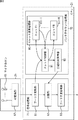
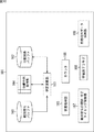
次に、図8を参照して、図4乃至図6を用いて説明した、複数スレッドを用いた学習処理を実行するCPU21が有する機能について説明する。すなわち、図8は、図3の音源分離装置11が有する機能を示す機能ブロック図である。
Next, a function of the
複数のマイクロホン61およびAD変換部62により構成される音信号取得部29により取得されてデジタルデータに変換された音信号は、主に観測信号の分離を行なう信号処理部71と、分離行列の学習処理を行なうバックグラウンド処理部72によって処理される。
The sound signal acquired by the sound
信号処理部71は、フーリエ変換部81、分離部82、および、フーリエ逆変換部83の機能を含み、バックグラウンド処理部72は、スレッド制御部91、スレッド演算処理部92、および、分離行列保持部93から構成されている。信号処理部71とバックグラウンド処理部72とは並列で動作する。
The signal processing unit 71 includes functions of a
フーリエ変換部81は、供給されたデータを、窓つきの短時間フーリエ変換によって周波数領域のデータへ変換し、分離部82およびスレッド制御部91に供給する。その際、フレームと呼ばれる一定個数のデータが生成される。以降の処理は、このフレームを単位として行なわれる。
The
分離部82は、フーリエ変換部81から供給された観測信号のフーリエ変換結果の1フレーム分であるX(t)(tは、フレーム番号であるものとする)と、分離行列保持部93から取得される、事前に求められた分離行列W[k](W[k]は、システムが起動されてからk番目に求められた分離行列である)とを乗じて、分離結果であるY(t)を生成して、フーリエ逆変換部83に供給する。
The
フーリエ逆変換部83は、分離部82から供給された分離結果Y(t)を時間領域の信号に変換し、例えば、音声認識などの後段の処理に対して供給する。後段の処理によっては、周波数領域のデータをそのまま使用する場合もあるので、その場合には、フーリエ逆変換を実行することなく、分離部82から供給された分離結果Y(t)を出力するものとしても良い。
The Fourier
スレッド制御部91は、フーリエ変換部81から供給された観測信号のフーリエ変換結果の1フレーム分であるX(t)を、スレッド演算処理部92に供給し、スレッド演算処理部92において実行される複数のスレッド101−1乃至101−Nの処理を制御する。そして、スレッド制御部91は、スレッド演算処理部92から供給された、学習の結果得られた分離処理用の分離行列Wを、分離行列保持部93に供給する。
The
スレッド演算処理部92において実行される複数のスレッド101−1乃至101−Nは、図4乃至図6を用いて説明したように、スレッド制御部91の制御に基づいて、状態を遷移し、それぞれ異なるタイミングで、与えられた観測信号を一定量だけ蓄積した後、ICAのバッチ処理を用いて観測信号から分離行列を求める学習処理を実行する。
As described with reference to FIGS. 4 to 6, the plurality of threads 101-1 to 101 -N executed in the thread
分離行列保持部93は、スレッド制御部91から供給された、学習の結果得られた分離処理用の分離行列Wを保持する。
The separation
信号処理部71およびバックグラウンド処理部72のそれぞれにおいて実行される処理は、並行して実行される。したがって、音源分離装置11の機能全体としてみると、観測信号に対して分離行列Wを随時適用する処理により、分離結果が逐次生成される一方で、適用される分離行列Wが、学習処理により求められて、ある程度頻繁に(例えば、ブロック長よりも短い期間で)更新されて適用される。
Processing executed in each of the signal processing unit 71 and the background processing unit 72 is executed in parallel. Therefore, as a whole function of the sound
図9は、スレッド制御部91が有する機能を更に詳細に示す、スレッド制御部91の機能ブロック図である。
FIG. 9 is a functional block diagram of the
現フレーム番号保持カウンタ131は、観測信号が1フレーム分供給されるごとに値が1インクリメントされ、所定の値に達すると初期値に戻るようになされている。なお、カウンタのインクリメントは、フレーム番号と同期させる代わりに、時間領域信号のサンプル番号と同期させても構わない。
The current frame
学習初期値保持部132は、それぞれのスレッドにおいて学習処理を実行する場合の分離行列Wの初期値を保持するものである。分離行列Wの初期値は、基本的には最新の分離行列と同一だが、異なる値を用いるものとしても良い。
The learning initial
蓄積開始予定タイミング指定情報保持部133は、蓄積を開始するタイミングを複数のスレッド間で一定間隔にするために用いられる情報である。なお、蓄積開始予定タイミングは、相対時刻を用いて表されていてもよいし、相対時刻の代わりにフレーム番号で管理してもよいし、時間領域信号のサンプル番号で管理しても良い。これについては他の「タイミング」を管理するための情報についても同様である。
The scheduled storage start timing designation
観測信号の蓄積タイミング情報保持部134は、分離部82で現在使用されている分離行列Wが、どのタイミングで取得された観測信号を基に学習されたものであるかを示す情報、すなわち、最新の分離行列に対応した観測信号の相対時刻またはフレーム番号を保持するものである。観測信号の蓄積タイミング情報保持部134には、対応する観測信号の蓄積開始タイミングと蓄積終了タイミングとの両方を格納しても良いが、ブロック長、すなわち、観測信号の蓄積時間が一定ならば、いずれか一方だけを保存すれば十分である。
The observation signal accumulation timing
また、スレッド制御部91は、それぞれのスレッドへリンクされているポインタ135を有し、これを用いて、複数のスレッドの処理を制御している。
The
次に、図10は、スレッド演算処理部92において実行されるそれぞれのスレッドの演算機能について説明するための機能ブロック図である。
Next, FIG. 10 is a functional block diagram for explaining the calculation function of each thread executed in the thread
スレッド101(複数のスレッド101−1乃至101−Nのそれぞれ)は、観測信号バッファ161、分離結果バッファ162、学習演算部163、および、分離行列保持部164の各モジュールの機能を用いて、バッチ処理のICAを実行する。
The thread 101 (each of the plurality of threads 101-1 to 101-N) uses a function of each module of the
観測信号バッファ161は、スレッド制御部91から供給される観測信号を保持するものであり、その容量は、1ブロック長に対応する観測信号の容量と同じか、それよりも大きいものである。ただし、後述する「観測信号のフレーム間引き」を行なう場合は、間引く分だけバッファの大きさを小さくしても構わない。
The
分離結果バッファ162には、学習演算部163により演算された、分離行列収束前の分離結果が保持される。
In the
学習演算部163は、観測信号バッファ161に蓄積されている観測信号を、分離行列保持部164に保持されている分離処理用の分離行列Wに基づいて分離して、分離結果バッファ162に蓄積するとともに、分離結果バッファ162に蓄積される分離結果を用いて、学習中の分離行列を更新する処理を実行する。
The learning
また、スレッドは、状態遷移マシンであり、現在の状態は、状態格納部165に格納されている。そして、スレッドの状態は、カウンタ166のカウンタ値によって、スレッド制御部91により制御される。
The thread is a state transition machine, and the current state is stored in the
観測信号の開始・終了タイミング保持部167には、学習に使用されている観測信号の開始タイミングと終了タイミングを示す情報のうちの少なくともいずれか一方が保持されている。タイミングを示す情報は、上述したように、フレーム番号やサンプル番号であっても良いし、相対時刻情報であっても良い。ここでも、開始タイミングと終了タイミングとの両方を格納しても良いが、ブロック長、すなわち、観測信号の蓄積時間が一定ならば、いずれか一方だけを保存すれば十分である。
The observation signal start / end
学習終了フラグ168は、学習が終了したことをスレッド制御部91に通知するために用いられるフラグである。スレッドの起動時においては、学習終了フラグ168はOFF(フラグが立っていない)にセットされ、学習が終了した時点でONにセットされる。そして、スレッド制御部91が、学習が終了したことを認識した後、スレッド制御部91の制御により、学習終了フラグ168は、再び、OFFにセットされる。
The learning
前処理用データ保持部169は、後述する前処理が施された観測信号を、元に戻す際に必要となるデータを保存しておく領域である。具体的には、例えば、前処理において、観測信号の正規化(分散を1に、平均を0にそろえる)が実行される場合、前処理用データ保持部169には、分散(または標準偏差やその逆数)や平均などの値が保持されるので、これを用いて正規化前の信号を復元することができる。また、例えば、前処理として無相関化(pre-whiteningとも称される)が実行される場合、前処理用データ保持部169には、無相関化で乗じた行列が保持される。
The preprocessing
状態格納部165、カウンタ166、観測信号の開始・終了タイミング保持部167に保持される値は、スレッド制御部91の制御により書き換えられる。例えば、このスレッドにおいて学習処理ループが回っている間であっても、スレッド制御部91は、カウンタ166の値を変更することができる。
The values held in the
状態遷移の実装については、それぞれのスレッド101が自分自身のカウンタ166の値に基づいて状態を自発的に変化させるという仕様にしても良いし、スレッド制御部91がカウンタ166の値や学習終了フラグ168の値に応じて、対応するスレッドに対して「指定された状態に遷移せよ」というコマンド(以降「状態遷移コマンド」と称するものとする)を発行し、それぞれのスレッドは、供給されたコマンドに応じて、その状態を遷移させるという仕様としてもよい。
Regarding the implementation of the state transition, the specification may be such that each
ここでは、スレッド制御部91がカウンタの値や学習終了フラグ168の値に応じて状態遷移コマンドを発行し、それぞれのスレッドは、供給されたコマンドに応じて、その状態を遷移させるそのコマンドを受けて状態を変化させる場合の処理を例として説明する。
Here, the
図11のシーケンス図を参照して、スレッド制御部91による複数のスレッドの制御について説明する。図11においては、スレッド制御部91が、スレッド1およびスレッド2の2つのスレッドを制御する場合を例として説明するが、スレッド数は、3以上であってもよいことは言うまでもない。
The control of a plurality of threads by the
なお、スレッド制御部91は、各スレッドのカウンタの値を参照したり変更(インクリメントや初期化や減算など)したりするため、厳密には、フレーム番号のインクリメントと同期して「カウンタ値」に関する情報が授受されるが、「カウンタ値」に関する情報の授受については、図11では省略する。
Since the
システムの起動直後、各スレッドは初期化されて「初期状態」とされる。そして、そのうちのいずれか一つ(ここでは、スレッド1)には、スレッド制御部91により、「蓄積中」へ状態を遷移させる状態遷移コマンドが発行されて、「蓄積中」状態に状態が遷移され、ほかのスレッド(ここでは、スレッド2)には、スレッド制御部91により、「待機中」へ状態を遷移させる状態遷移コマンドが発行されて、「待機中」状態に状態が遷移される。
Immediately after system startup, each thread is initialized to an “initial state”. Then, for any one of them (here, thread 1), the
「蓄積中」状態のスレッド1には、スレッド制御部91により観測信号が供給される。
An observation signal is supplied to the
そして、スレッド制御部91は、カウンタの値に基づいて、それぞれのスレッドの状態を遷移させる。具体的には、スレッド2が「待機中」状態に遷移されてから、ブロックシフト幅に対応する所定のカウント値がカウントされた場合、スレッド制御部91は、スレッド2に、「蓄積中」へ状態を遷移させる状態遷移コマンドを発行する。スレッド2の状態は、「蓄積中」に遷移され、スレッド制御部91から観測信号の供給を受ける。
Then, the
また、スレッド1が「蓄積中」状態に遷移されてから、ブロック長に対応する所定のカウント値がカウントされた場合、スレッド制御部91は、スレッド1に、「学習中」へ状態を遷移させる状態遷移コマンドを発行する。スレッド1の状態は、「学習中」に遷移される。スレッド1において学習が終了し、分離行列Wの値が収束した場合、スレッド1の学習終了フラグ168がONとなって、スレッド制御部91は、学習の終了を認識することができ、スレッド1からスレッド制御部91に学習の結果得られた分離行列Wが供給される。
In addition, when a predetermined count value corresponding to the block length is counted after the
そして、学習の終了を認識し、分離行列Wの値の供給を受けたスレッド制御部91は、カウンタの値を参照し、カウンタの値から計算される蓄積開始タイミングが、蓄積開始予定タイミング指定情報保持部133に保持されている値から計算されるタイミングを超えていない場合、スレッド1に「待機中」へ状態を遷移させる状態遷移コマンドを発行する。スレッド1の状態は、「待機中」に遷移される。そして、スレッド制御部91は、カウンタの値がスレッド長となったとき、スレッド1に「蓄積中」へ状態を遷移させる状態遷移コマンドを発行する。スレッド1の状態は、「蓄積中」に遷移される。「蓄積中」状態のスレッド1には、スレッド制御部91により観測信号が供給される。
The
そして、同様に、スレッド2が「蓄積中」状態に遷移されてから、ブロック長に対応する所定のカウント値がカウントされた場合、スレッド制御部91は、スレッド2に、「学習中」へ状態を遷移させる状態遷移コマンドを発行する。スレッド2の状態は、「学習中」に遷移される。スレッド2において学習が終了し、分離行列Wの値が収束した場合、スレッド2の学習終了フラグ168がONとなって、スレッド制御部91は、学習の終了を認識することができ、スレッド2からスレッド制御部91に学習の結果得られた分離行列Wが供給される。
Similarly, when a predetermined count value corresponding to the block length is counted after the
そして、学習の終了を認識し、分離行列Wの値の供給を受けたスレッド制御部91は、カウンタの値を参照し、カウンタの値から計算される蓄積開始タイミングが、蓄積開始予定タイミング指定情報保持部133に保持されている値から計算されるタイミングを超えていない場合、スレッド2に「待機中」へ状態を遷移させる状態遷移コマンドを発行する。スレッド2の状態は、「待機中」に遷移される。そして、スレッド制御部91は、カウンタの値がスレッド長となったとき、スレッド2に「蓄積中」へ状態を遷移させる状態遷移コマンドを発行する。スレッド2の状態は、「蓄積中」に遷移される。「蓄積中」状態のスレッド2には、スレッド制御部91により観測信号が供給される。
The
このようにして、状態遷移コマンドの発行と、状態遷移が繰り返されて、複数のスレッドにおいて、異なるタイミングで学習処理が行われて、分離行列Wがスレッド制御部91に供給される。そして、それらの学習処理も、最新の分離行列Wに基づいて実行される。
In this way, the issuance of the state transition command and the state transition are repeated, the learning process is performed at different timings in the plurality of threads, and the separation matrix W is supplied to the
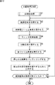
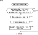
次に、図12のフローチャートを参照して、音源分離装置11において実行される、複数音源からの音の分離処理について説明する。
Next, sound separation processing from a plurality of sound sources executed in the sound
ステップS1において、図14のフローチャートを用いて後述する初期化処理が実行される。 In step S1, an initialization process to be described later is executed using the flowchart of FIG.
ステップS2において、フーリエ変換部81は、音信号取得部29により複数のマイクで集音され、AD変換部62により所定のサンプルレートでサンプリングされてデジタル信号に変換された観測信号を取得する。
In step S <b> 2, the
ステップS3において、フーリエ変換部81は、供給された観測信号に対して、短時間フーリエ変換を実行する。
In step S3, the
図13を参照して、短時間フーリエ変換について説明する。 The short-time Fourier transform will be described with reference to FIG.
フーリエ変換部81は、図13の上段に示される観測信号xk(ここでは、kはマイクの番号)から、図中、α、β、γで示されるように、一定長を切り出し、それらにハニング窓やサイン窓等の窓関数を作用させる。この切り出した単位(図中のα、β、γ)がフレームである。そして、フーリエ変換部81は、1フレーム分のデータに短時間フーリエ変換をかけることにより、周波数領域のデータであるスペクトルXk(t)を得る(ここでは、tはフレーム番号)。また、図中、α、β、γで示されるように、切り出すフレームの間には重複があってもよい。これにより、連続するフレームのスペクトルXk(t-1)、Xk(t)、Xk(t+1)を、滑らかに変化させることができる。図13の下段に示される、スペクトルをフレーム番号に従って並べたものは、スペクトログラムと称される。
The
入力チャンネルが複数(マイクの個数分)あるため、フーリエ変換部81は、フーリエ変換をチャンネル数だけ行なう。以降では、全チャンネル、1フレーム分のフーリエ変換結果を、次の式(11)に示されるベクトルX(t)で表わすものとする。
Since there are a plurality of input channels (the number of microphones), the
なお、式(11)において、nは、チャンネル数、すなわち、マイク数であり、Mは、周波数ビンの総数であり、短時間フーリエ変換のポイント数をLとすると、M=L/2+1である。 In Equation (11), n is the number of channels, that is, the number of microphones, M is the total number of frequency bins, and M = L / 2 + 1, where L is the number of points in the short-time Fourier transform. It is.
ステップS4において、図15のフローチャートを用いて後述するスレッド制御処理が実行される。 In step S4, a thread control process to be described later is executed using the flowchart of FIG.
ステップS5において、分離部82は、バックグラウンド処理部72の分離行列保持部93から取得した分離行列Wを用いて、ステップS3においてフーリエ変換された観測信号観測信号X(t)に対して分離処理を実行する。
In step S5, the
すなわち、分離行列Wは、次の式(12)で表される。そして、次の式(13)で表される分離結果Y(t)は、式(14)を用いて求めることができる。 That is, the separation matrix W is expressed by the following equation (12). Then, the separation result Y (t) represented by the following equation (13) can be obtained using equation (14).
![]()
![]()
なお、式(12)で表わされる行列Wは、対角行列からなる疎行列であり、また、要素の0は、それぞれの対角行列において対角成分以外の値は常に0であることを表わしている。
Note that the matrix W represented by the equation (12) is a sparse matrix composed of diagonal matrices, and the
ステップS6において、フーリエ逆変換部83は、分離結果Y(t)に対して、逆フーリエ変換を実行し、時間領域の信号に戻す。その際、必要に応じて overlap add(重複足し合わせ)が行なわれる。さらに、フレーム間で不連続性が発生するのを防ぐため、1フレーム分のデータの逆フーリエ変換結果に対して、サイン窓等の適切な窓関数を適用した上で overlap addが行なわれるようにしても良い。この処理は、weighted overlap add(WOLA)と称される。
In step S6, the Fourier
フーリエ逆変換部83は、ステップS7において、逆フーリエ変換によって得られた信号、すなわち、時間領域の信号を、必要に応じてバッファリングし、ステップS8において、例えば、音声認識処理など、後段の所定の処理を実行するために出力する。
In step S7, the inverse
ステップS9において、フーリエ変換部81は、観測信号の取得が終了したか否かを判断する。ステップS9において、観測信号の取得が終了していないと判断された場合、処理は、ステップS2に戻り、それ以降の処理が繰り返される。ステップS9において、観測信号の取得が終了したと判断された場合、処理は終了される。
In step S9, the
このような処理により、音源分離装置11において、複数音源からの音の分離が実行される。
With such processing, the sound
次に、図14のフローチャートを参照して、図12のステップS1において実行された、初期化処理について説明する。 Next, the initialization process executed in step S1 of FIG. 12 will be described with reference to the flowchart of FIG.
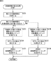
ステップS31において、スレッド制御部91は、自分自身を初期化する。
In step S31, the
具体的には、スレッド制御部91において、現フレーム番号保持カウンタ131が初期化されてその値が0とされ、学習初期値保持部132に適切な初期値が代入される。例えば、初期値は単位行列でも良いし、前回のシステム終了時の分離行列Wが保存されている場合は、前回のシステム終了時の分離行列W、またはこの分離行列に適切な変換を作用させたものを使用しても良い。また、例えば、画像や先見知識等の情報により、音源の方向がある程度の精度で推定できるような場合には、音源方向に基づいて初期値を算出して、設定するものとしてもよい。
Specifically, in the
そして、蓄積開始予定タイミング指定情報保持部133には、(必要スレッド数−1)×block_shiftの値が設定される。この値は、一番大きなスレッド番号を有するスレッドの蓄積が開始するタイミング(フレーム番号)である。そして、観測信号の蓄積タイミング情報保持部134には、最新の分離行列に対応した観測信号を示すタイミング情報(ブレーム番号または相対時刻情報)が保持されるので、ここでは、初期化されて、0が保持される。
Then, in the accumulation start scheduled timing designation
なお、分離行列保持部93にも、初期化された場合の学習初期値保持部132と同様に、適切な初期値が保持される。すなわち、分離行列保持部93に保持される初期値は、単位行列でも良いし、前回のシステム終了時の分離行列が保存されている場合は、前回のシステム終了時の分離行列W、またはこの分離行列に適切な変換を作用させたものを使用しても良い。また、例えば、画像や先見知識等の情報により、音源の方向がある程度の精度で推定できるような場合には、音源方向に基づいて初期値を算出して、設定するものとしてもよい。
Note that the separation
ステップS32において、スレッド制御部91は、スレッド演算処理部92において実行されるスレッドを必要な数iだけ確保し、それらの状態を「初期化」状態とする。
In step S32, the
ここで、必要なスレッドの数iは、thread_len/block_shiftの小数点以下を切り上げる(すなわち、thread_len/block_shiftよりも大きく最も値の近い整数)ことにより求められる。 Here, the number of necessary threads i is obtained by rounding up the decimal point of thread_len / block_shift (that is, an integer larger than thread_len / block_shift and closest in value).
ステップS33において、スレッド制御部91は、スレッドループを開始して、全てのスレッドの初期化が終了するまで、初期化未処理のスレッドを検出して、ステップS34乃至ステップS39の処理を実行する。
In step S33, the
ステップS34において、スレッド制御部91は、スレッド番号は1であるか否かを判断する。
In step S <b> 34, the
ステップS34において、スレッド番号は1であると判断された場合、ステップS35において、スレッド制御部91は、スレッド番号1のスレッド(例えば、スレッド101−1)を制御して、そのカウンタ166を初期化(例えば、0にセット)する。
If it is determined in step S34 that the thread number is 1, in step S35, the
ステップS36において、スレッド制御部91は、スレッド番号1のスレッド(例えば、スレッド101−1)に、「蓄積中」状態に状態を遷移させるための状態遷移コマンドを発行して、処理は、後述するステップS39にすすむ。
In step S36, the
ステップS34において、スレッド番号は1ではないと判断された場合、ステップS37において、スレッド制御部91は、対応するスレッド(スレッド101−2乃至スレッド101−iのうちのいずれか)のカウンタ166の値を、thread_len−block_shift×(スレッド番号-1)に設定する。
If it is determined in step S34 that the thread number is not 1, in step S37, the
ステップS38において、スレッド制御部91は、「待機中」状態に状態を遷移させるための状態遷移コマンドを発行する。
In step S38, the
ステップS36、または、ステップS38の処理の終了後、ステップS39において、スレッド制御部91は、スレッド内のまだ初期化されていない情報、すなわち、状態格納部165に格納された状態を示す情報、および、カウンタ166のカウンタ値以外の情報を初期化する。具体的には、例えば、スレッド制御部91は、学習終了フラグ168をOFFにセットし、観測信号の開始・終了タイミング保持部167、および、前処理用データ保持部169の値を初期化(例えば、0にセット)する。
After the process of step S36 or step S38 is completed, in step S39, the
スレッド演算処理部92に確保された全てのスレッド、すなわち、スレッド101−1乃至スレッド101−iが初期化された場合、ステップS40において、スレッドループが終了され、処理は、図12のステップS1に戻り、ステップS2に進む。
When all the threads secured in the thread
このような処理により、スレッド制御部91は、スレッド演算部に確保された複数のスレッドのすべてを初期化する。
By such processing, the
なお、ここでは、立ち上げられたスレッドの数iだけ、ステップS33乃至ステップS40の処理のループが繰り返されるものとして説明したが、処理ループを繰り返す代わりに、スレッドの個数iの並列処理を実行するものとしてもよい。これ以降の処理ループを繰り返す部分についても、同様に、処理ループを繰り返す代わりに、並列処理を実行するようにしても良い。 Here, it has been described that the processing loop of step S33 to step S40 is repeated for the number i of the activated threads, but parallel processing for the number i of threads is executed instead of repeating the processing loop. It may be a thing. Similarly, for the part where the subsequent processing loop is repeated, parallel processing may be executed instead of repeating the processing loop.
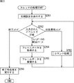
次に、図15のフローチャートを参照して、図12のステップS4において、スレッド制御部91によって実行される、スレッド制御処理について説明する。
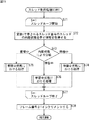
Next, the thread control process executed by the
ステップS71において、スレッド制御部91は、スレッドループを開始し、制御実行するスレッドのスレッド番号を示す変数sをs=1として、1つのスレッドの処理が終了すると変数sを1インクリメントして、s=iとなるまで、ステップS72乃至ステップS77のスレッドループの処理を繰り返し実行する。
In step S71, the
ステップS72において、スレッド制御部91は、変数sで示されるスレッド番号のスレッドの状態格納部165に保持されている、そのスレッドの内部状態を示す情報を取得する。
In step S72, the
ステップS73において、スレッド制御部91は、変数sで示されるスレッド番号のスレッドの内部状態を検出する。
In step S73, the
ステップS73において、変数sで示されるスレッド番号のスレッドの状態は、「待機中」状態であると検出された場合、ステップS74において、スレッド制御部91は、図16のフローチャートを用いて後述する、待機中状態における処理を実行し、処理は、後述するステップS77に進む。
In step S73, when it is detected that the state of the thread having the thread number indicated by the variable s is in the “waiting” state, in step S74, the
ステップS73において、変数sで示されるスレッド番号のスレッドの状態は、「蓄積中」状態であると検出された場合、ステップS75において、スレッド制御部91は、図17のフローチャートを用いて後述する、蓄積中状態における処理を実行し、処理は、後述するステップS77に進む。
If it is detected in step S73 that the state of the thread having the thread number indicated by the variable s is the “accumulating” state, in step S75, the
ステップS73において、変数sで示されるスレッド番号のスレッドの状態は、「学習中」状態であると検出された場合、ステップS76において、スレッド制御部91は、図18のフローチャートを用いて後述する、学習中状態における処理を実行する。
If it is detected in step S73 that the state of the thread having the thread number indicated by the variable s is the “learning” state, in step S76, the
ステップS74、ステップS75、または、ステップS76の処理の終了後、ステップS77において、スレッド制御部91は、変数sを1インクリメントする。そして、制御実行するスレッドのスレッド番号を示す変数sが、s=iとなったとき、スレッドループを終了する。
After the process of step S74, step S75, or step S76 ends, in step S77, the
ステップS78において、スレッド制御部91は、現フレーム番号保持カウンタ131に保持されているフレーム番号を1インクリメントし、処理は、図12のステップS4に戻り、ステップS5に進む。
In step S78, the
このような処理により、スレッド制御部91は、複数のスレッドの全てを、それらの状態に応じて制御することができる。
Through such processing, the
なお、ここでは、立ち上げられたスレッドの数iだけ、スレッドループが繰り返されるものとして説明したが、スレッドループを繰り返す代わりに、スレッドの個数iの並列処理を実行するものとしてもよい。 Here, the description has been made on the assumption that the thread loop is repeated by the number i of the activated threads, but parallel processing of the number i of threads may be executed instead of repeating the thread loop.
次に、図16のフローチャートを参照して、図15のステップS74において実行される、待機中状態における処理について説明する。 Next, with reference to the flowchart of FIG. 16, the process in the standby state executed in step S74 of FIG. 15 will be described.
この待機中状態における処理は、図15を用いて説明したスレッド制御処理における変数sに対応するスレッドの状態が「待機中」状態であるときに、スレッド制御部91において実行される処理である。
The process in the waiting state is a process executed in the
ステップS111において、スレッド制御部91は、対応するスレッド101のカウンタ166を、1インクリメントする。
In step S111, the
ステップS112において、スレッド制御部91は、対応するスレッド101のカウンタ166の値は、スレッド長(thread_len)より小さいか否かを判断する。ステップS112において、カウンタ166の値は、スレッド長より小さいと判断された場合、処理は、図15のステップS74に戻り、ステップS77に進む。
In step S112, the
ステップS112において、カウンタ166の値は、スレッド長より小さくないと判断された場合、ステップS113において、スレッド制御部91は、「蓄積中」状態に状態を遷移させるための状態遷移コマンドを、対応するスレッド101に発行する。
If it is determined in step S112 that the value of the
すなわち、スレッド制御部91は、図6を用いて説明した状態遷移図において、「待機中」であるスレッドを、「蓄積中」に遷移させるための状態遷移コマンドを発行する。
That is, the
ステップS114において、スレッド制御部91は、対応するスレッド101のカウンタ166を初期化(例えば、0にセット)し、観測信号の開始・終了タイミング保持部167に、観測信号の蓄積開始タイミング情報、すなわち、現フレーム番号保持カウンタ131に保持されている現在のフレーム番号、または、それと同等の相対時刻情報などを設定して、処理は、図15のステップS74に戻り、ステップS77に進む。
In step S114, the
このような処理により、スレッド制御部91は、「待機中」状態であるスレッドを制御し、そのカウンタ166の値に基づいて、「蓄積中」に状態を遷移させることができる。
Through such processing, the
次に、図17のフローチャートを参照して、図15のステップS75において実行される、蓄積中状態における処理について説明する。 Next, with reference to the flowchart of FIG. 17, the process in the accumulation state executed in step S75 of FIG. 15 will be described.
この蓄積中状態における処理は、図15を用いて説明したスレッド制御処理における変数sに対応するスレッドの状態が「蓄積中」状態であるときに、スレッド制御部91において実行される処理である。
The process in the accumulation state is a process executed in the
ステップS141において、スレッド制御部91は、1フレーム分の観測信号X(t)を、学習のために、対応するスレッド101に供給する。この処理は、図9を用いて説明した、スレッド制御部91からそれぞれのスレッドへの観測信号の供給に対応する。
In step S141, the
ステップS142において、スレッド制御部91は、対応するスレッド101のカウンタ166を、1インクリメントする。
In step S142, the
ステップS143において、スレッド制御部91は、対応するスレッド101のカウンタ166の値は、ブロック長(block_len)より小さいか否か、換言すれば、対応するスレッドの観測信号バッファ161が満杯であるか否かを判断する。ステップS143において、カウンタ166の値は、ブロック長より小さい、換言すれば、対応するスレッドの観測信号バッファ161が満杯ではないと判断された場合、処理は、図15のステップS75に戻り、ステップS77に進む。
In step S143, the
ステップS143において、カウンタ166の値は、ブロック長より小さくない、換言すれば、対応するスレッドの観測信号バッファ161が満杯であると判断された場合、ステップS144において、スレッド制御部91は、「学習中」状態に状態を遷移させるための状態遷移コマンドを、対応するスレッド101に発行して、処理は、図15のステップS75に戻り、ステップS77に進む。
When it is determined in step S143 that the value of the
すなわち、スレッド制御部91は、図6を用いて説明した状態遷移図において、「蓄積中」であるスレッドを、「学習中」に遷移させるための状態遷移コマンドを発行する。
That is, the
このような処理により、スレッド制御部91は、「蓄積中」状態であるスレッドに観測信号を供給してその蓄積を制御し、そのカウンタ166の値に基づいて、「蓄積中」から「学習中」に状態を遷移させることができる。
Through such processing, the
次に、図18のフローチャートを参照して、図15のステップS76において実行される、学習中状態における処理について説明する。 Next, the process in the learning state that is executed in step S76 in FIG. 15 will be described with reference to the flowchart in FIG.
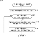
この学習中状態における処理は、図15を用いて説明したスレッド制御処理における変数sに対応するスレッドの状態が「学習中」状態であるときに、スレッド制御部91において実行される処理である。
The process in the learning state is a process executed in the
ステップS171において、スレッド制御部91は、対応するスレッド101の学習終了フラグ168がONであるか否かを判断する。ステップS171において、学習フラグがONであると判断された場合、処理は、後述するステップS175に進む。
In step S171, the
ステップS171において、学習フラグがONではないと判断された場合、すなわち、対応するスレッドにおいて学習処理が実行中である場合、ステップS172において、スレッド制御部91は、対応するスレッド101のカウンタ166を、1インクリメントする。
If it is determined in step S171 that the learning flag is not ON, that is, if the learning process is being executed in the corresponding thread, in step S172, the
ステップS173において、スレッド制御部91は、対応するスレッド101のカウンタ166の値は、スレッド長(thread_len)より小さいか否かを判断する。ステップS173において、カウンタ166の値は、スレッド長より小さいと判断された場合、処理は、図15のステップS76に戻り、ステップS77に進む。
In step S173, the
ステップS173において、カウンタ166の値は、スレッド長より小さくないと判断された場合、ステップS174において、スレッド制御部91は、カウンタ166の値から所定の値を減算し、処理は、図15のステップS76に戻り、ステップS77に進む。
When it is determined in step S173 that the value of the
学習中にカウンタの値がスレッド長に達した場合とは、学習にかかる時間が長くなってしまい、「待機中」状態の時間が存在しなくなった場合である。その場合、学習はまだ継続しており、観測信号バッファ161は利用されているため、次の蓄積を開始することができない。そこで、スレッド制御部91は、学習が終了するまで、次の蓄積の開始、すなわち、「蓄積中」状態へ状態を遷移させるための状態遷移コマンドの発行を延期する。そのため、スレッド制御部91は、カウンタ166の値から所定の値を減算する。減算する値は、例えば、1であっても良いが、それよりも大きな値でも良く、例えば、スレッド長の10%などといった値であっても良い。
The case where the value of the counter reaches the thread length during learning is a case where the time required for learning becomes long and there is no time in the “waiting” state. In this case, learning is still continuing, and the
なお、「蓄積中」状態への状態の遷移の延期を行なうと、蓄積開始時刻がスレッド間で不等間隔となり、最悪の場合、複数のスレッドでほぼ同一の区間の観測信号を蓄積してしまう可能性もある。そうなると、いくつかのスレッドが無意味になるだけでなく、例えば、CPU21が実行するOSのマルチスレッドの実装によっては、1つのCPU21で複数の学習が同時に動くことになって、更に学習時間が増大し、間隔が一層不均等になってしまう可能性がある。
Note that if the state transition to the “accumulating” state is postponed, the accumulation start time becomes unequal between threads, and in the worst case, observation signals in almost the same section are accumulated in a plurality of threads. There is a possibility. In that case, not only some threads become meaningless, but depending on the multi-threading implementation of the OS executed by the
そのような事態を防ぐためには、他のスレッドの待機時間を調整して蓄積開始タイミングが再び等間隔になるように調整すればよい。他のスレッドの待機時間の調整については、図20を用いて後述する。 In order to prevent such a situation, it is only necessary to adjust the waiting time of other threads so that the accumulation start timing becomes equal intervals again. The adjustment of the waiting time of other threads will be described later with reference to FIG.
ステップS171において、学習フラグがONであると判断された場合、すなわち、対応するスレッドにおいて学習処理が終了した場合、ステップS175において、スレッド制御部91は、対応するスレッド101の学習終了フラグ168をOFFにする。
If it is determined in step S171 that the learning flag is ON, that is, if the learning process is completed in the corresponding thread, the
ステップS176において、図19を用いて後述する、分離行列更新処理が実行され、学習によって求められた分離行列Wの値が最も新しい観測信号を基に算出されたものであった場合、分離部82による分離処理に用いられるとともに、他のスレッドの学習に反映される。
In step S176, a separation matrix update process, which will be described later with reference to FIG. 19, is executed, and when the value of the separation matrix W obtained by learning is calculated based on the latest observation signal, the
ステップS177において、図20を用いて後述する、待機時間の設定処理が実行されて、処理は、図15のステップS76に戻り、ステップS77に進む。 In step S177, a standby time setting process, which will be described later with reference to FIG. 20, is executed, and the process returns to step S76 in FIG. 15 and proceeds to step S77.
なお、図20を用いて後述する待機時間の設定処理において、スレッド制御部91は、対応するスレッドに対して、「待機中」か「蓄積中」かのいずれかの状態に状態を遷移させるための状態遷移コマンドを発行する。
In the waiting time setting process, which will be described later with reference to FIG. 20, the
このような処理により、スレッド制御部91は、対応するスレッドの学習終了フラグ168を参照して、「学習中」状態のスレッドの学習が終了したか否かを判断し、学習が終了した場合、分離行列Wを更新し、待機時間を設定するとともに、「学習中」状態から、「待機中」または「蓄積中」に状態を遷移させることができる。
By such processing, the
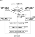
次に、図19のフローチャートを参照して、図18のステップS176において実行される、分離行列更新処理について説明する。 Next, with reference to the flowchart of FIG. 19, the separation matrix update process executed in step S176 of FIG. 18 will be described.
ステップS201において、スレッド制御部91は、スレッドの、観測信号の開始・終了タイミング保持部167に保持されている観測信号の開始タイミングは、観測信号の蓄積タイミング情報保持部134に保持されている、現在の分離行列に対応した蓄積開始タイミングよりも早いか否かを判断する。
In step S201, the
すなわち、図7に示されるように、スレッド1の学習とスレッド2の学習とは、その一部で時間が重なっている。この図では、学習201のほうが、学習202より先に終了しているが、例えば、それぞれの学習にかかる時間によっては、学習201よりも学習202のほうが先に終了してしまう場合もあり得る。
That is, as shown in FIG. 7, the learning of the
ここで、ステップS201の判断が実行されず、学習の終了が遅いものが最新の分離行列として扱われてしまった場合、スレッド2由来の分離行列W2が、より古いタイミングで取得された観測信号によって学習されて得られたスレッド1由来の分離行列W1に上書きされてしまう。そこで、新しいタイミングで取得された観測信号によって得られた分離行列が最新の分離行列として扱われるように、観測信号の開始・終了タイミング保持部167に保持されている観測信号の開始タイミングと、観測信号の蓄積タイミング情報保持部134に保持されている現在の分離行列に対応した蓄積開始タイミングとが比較される。
Here, when the determination in step S201 is not executed and the one whose learning is late is treated as the latest separation matrix, the separation matrix W2 derived from the
ステップS201において、観測信号の開始タイミングは、現在の分離行列に対応した蓄積開始タイミングよりも早いと判断された場合、換言すれば、このスレッドの学習の結果得られた分離行列Wは、現在、観測信号の蓄積タイミング情報保持部134に保持されている分離行列Wよりも早いタイミングで観測された信号に基づいて学習されていると判断された場合、このスレッドの学習の結果得られた分離行列Wは利用されないので、処理は、図18のステップS176に戻り、ステップS177に進む。
In step S201, when it is determined that the start timing of the observation signal is earlier than the accumulation start timing corresponding to the current separation matrix, in other words, the separation matrix W obtained as a result of learning of this thread is When it is determined that learning is performed based on a signal observed at an earlier timing than the separation matrix W held in the observation signal accumulation timing
ステップS201において、観測信号の開始タイミングは、現在の分離行列に対応した蓄積開始タイミングよりも早くないと判断された場合、すなわち、このスレッドの学習の結果得られた分離行列Wは、現在、観測信号の蓄積タイミング情報保持部134に保持されている分離行Wよりも遅いタイミングで観測された信号に基づいて学習されていると判断された場合、ステップS202において、スレッド制御部91は、対応するスレッドの学習によって得られた分離行列Wを取得し、分離行列保持部93に供給して、設定する。
In step S201, when it is determined that the start timing of the observation signal is not earlier than the accumulation start timing corresponding to the current separation matrix, that is, the separation matrix W obtained as a result of learning of this thread is currently observed. When it is determined that learning is performed based on a signal observed at a timing later than the separation row W held in the signal accumulation timing
ステップS203において、スレッド制御部91は、学習初期値保持部132に保持される、それぞれのスレッドにおける学習の初期値を設定する。
In step S <b> 203, the
具体的には、スレッド制御部91は、学習初期値として、対応するスレッドの学習によって得られた分離行列Wを設定するものとしてもよいし、対応するスレッドの学習によって得られた分離行列Wを用いて演算される、分離行列Wとは異なる値を設定するものとしても良い。
Specifically, the
ステップS204において、スレッド制御部91は、対応するスレッドの、観測信号の開始・終了タイミング保持部167に保持されているタイミング情報を、観測信号の蓄積タイミング情報保持部134に設定し、処理は、図18のステップS176に戻り、ステップS177に進む。
In step S204, the
ステップS204の処理により、現在使用中、すなわち、分離行列保持部93に保持されている分離行列Wが、どの時間区間の観測信号から学習されたものであるかが示される。
The processing in step S204 indicates which time interval the separation matrix W currently in use, that is, the separation matrix W held in the separation
このような処理により、新しいタイミングで取得された観測信号によって得られた分離行列が最新の分離行列として設定される。 By such processing, the separation matrix obtained by the observation signal acquired at the new timing is set as the latest separation matrix.
なお、ステップS203の処理においては、学習初期値保持部132により保持されている学習の初期値は、最新の学習結果である分離行列Wと等しい値であっても良いし、これとは異なる値を用いるものとしても良い。
In the process of step S203, the learning initial value held by the learning initial
学習初期値保持部132により保持される学習の初期値を、最新の学習結果である分離行列Wと等しい値とした場合、異なるブロックから求まった分離行列の間でも、「どのチャンネルにどの音源が出力されるか」という対応関係が維持される可能性が高くなる。
When the initial value of learning held by the learning initial
これに対して、スレッドの個数やブロックのシフト幅の値によっては、最新の学習結果である分離行列Wと等しい値を学習初期値保持部132にしただけでは、「どのチャンネルにどの音源が出力されるか」という対応関係が維持されない場合もある。
On the other hand, depending on the number of threads and the value of the block shift width, if the learning initial
具体的には、図7に示されるように4つのスレッドが並行して動作し、スレッド長はブロック長の2倍、ブロックのシフト幅はブロック長の1/2であり、また、学習に要する時間がブロックのシフト幅よりも長い場合、学習の初期値として最新の学習結果である分離行列Wを用いると、例えば、スレッド3に含まれる学習は、学習204−1も、学習204−2も、いずれにおいても、スレッド1に由来する分離行列Wを、初期値として利用することになる。そして、同様に、スレッド1に含まれる学習は、スレッド3に由来する分離行列Wを初期値として利用し、スレッド2に含まれる学習は、スレッド4に由来する分離行列Wを初期値として利用し、スレッド4に含まれる学習は、スレッド2に由来する分離行列Wを初期値として利用する。
Specifically, as shown in FIG. 7, four threads operate in parallel, the thread length is twice the block length, the block shift width is 1/2 the block length, and learning is required. When the time is longer than the block shift width, using the separation matrix W that is the latest learning result as the initial value of learning, for example, learning included in the
すなわち、スレッド間の初期値の受け渡しに注目すると、スレッド1およびスレッド3の系列と、スレッ2およびスレッド4の系列とが存在し、これらの系列間では、初期値の相互利用はなされない。
That is, paying attention to the passing of initial values between threads, there are a series of
このように、初期値の相互利用が行われない系列が複数存在すると、それらの系列間で分離行列が異なったものになる可能性があり、最悪の場合、分離行列が更新されるごとに、「どのチャンネルにどの音源が出力されるか」という対応関係が変化してしまう可能性がある。 In this way, when there are a plurality of sequences in which the initial values are not mutually used, the separation matrix may be different between the sequences. In the worst case, each time the separation matrix is updated, There is a possibility that the correspondence relationship “which sound source is output to which channel” may change.
そこで、初期値の相互利用が行われない系列ができることを防ぐために、学習の初期値として、最新の学習結果である分離行列の他に、それ以前の学習で求まった分離行列の値も反映させて算出される値(最新の学習結果である分離行列を分離行列W[k]として、分離行列W[k-1]、分離行列W[k-2]などの値も反映させて算出される値)を用いるようにすることができる。 Therefore, in order to prevent the generation of sequences in which the initial values are not mutually used, in addition to the separation matrix that is the latest learning result, the value of the separation matrix obtained by previous learning is reflected as the initial value of learning. (The separation matrix that is the latest learning result is the separation matrix W [k] , and the values such as the separation matrix W [k-1] and the separation matrix W [k-2] are also reflected. Value) can be used.
例えば、学習の初期値をW_initとすると、学習初期値保持部132に保持される学習の初期値をW_init=W[k]としても良いし、W_init=(W[k]+W[k-1] +・・・+W[k-N])/(N+1)としてもよいし、所定の重み付け係数aを用いて、W_initにaW+(1-a)W_initを代入するようにしても良い。
For example, if the initial value of learning is W_init, the initial value of learning held in the learning initial
次に、図20のフローチャートを参照して、図18のステップS177において実行される、待機時間の設定処理について説明する。 Next, the standby time setting process executed in step S177 of FIG. 18 will be described with reference to the flowchart of FIG.
ステップS231において、スレッド制御部91は、残りの待機時間を計算する。
In step S231, the
具体的には、スレッド制御部91は、残り待機時間(フレーム個数)をrest、蓄積開始予定タイミング指定情報保持部133に保持されている、蓄積開始予定タイミング(フレーム番号、または、対応する相対時刻)をCt、現フレーム番号保持カウンタ131に保持されている現フレーム番号をFt、ブロックのシフト幅をblock_shiftとして、残り待機時間restを、rest=Ct+block_shift−Ftを基に算出する。すなわち、Ct+block_shiftが、次々回蓄積開始予定時刻を意味するため、そこからFtを引くことで、「次々回蓄積開始予定時刻までの残り時間」が求まるのである。
Specifically, the
ステップS232において、スレッド制御部91は、残りの待機時間restの計算結果は正の値であるか否かを判断する。ステップS232において、残りの待機時間restの計算結果は正の値ではない、すなわち、負の値であると判断された場合、処理は、後述するステップS236に進む。
In step S232, the
ステップS232において、残りの待機時間restの計算結果は正の値であると判断された場合、ステップS233において、スレッド制御部91は、「待機中」状態に状態を遷移させるための状態遷移コマンドを、対応するスレッドに発行する。
If it is determined in step S232 that the calculation result of the remaining waiting time rest is a positive value, in step S233, the
ステップS234において、スレッド制御部91は、対応するスレッドのカウンタ166の値を、thread_len−restに設定する。そうすることで、カウンタの値が、thread_lenに達するまでの間は、「待機中」状態が継続される。
In step S234, the
ステップS235において、スレッド制御部91は、蓄積開始予定タイミング指定情報保持部133に保持されている値Ctに、block_shiftの値を加算する、すなわち、蓄積開始予定タイミング指定情報保持部133に次回の蓄積開始タイミングである、Ct+block_shiftの値を設定し、処理は、図18のステップS177に戻り、図15のステップS76に戻り、ステップS77に進む。
In step S235, the
ステップS232において、残りの待機時間restの計算結果は正の値ではない、すなわち、負の値であると判断された場合、予定された蓄積開始タイミングを過ぎているのにもかかわらず蓄積が始まっていないことを意味するので、直ちに蓄積を開始する必要がある。そこで、ステップS236において、スレッド制御部91は、「蓄積中」状態に状態を遷移させるための状態遷移コマンドを、対応するスレッドに発行する。
In step S232, when it is determined that the calculation result of the remaining waiting time rest is not a positive value, that is, a negative value, accumulation starts even though the scheduled accumulation start timing has passed. It means that it is not, so it is necessary to start accumulation immediately. Therefore, in step S236, the
ステップS237において、スレッド制御部91は、カウンタの値を初期化(例えば0をセット)する。
In step S237, the
ステップS238において、スレッド制御部91は、蓄積開始予定タイミング指定情報保持部133に次回の蓄積開始タイミング、すなわち、現フレーム番号であるFtを設定し、処理は、図18のステップS177に戻り、図15のステップS76に戻り、ステップS77に進む。
In step S238, the
このような処理により、それぞれのスレッドにおける「学習中」状態にかかる時間に応じて、「待機中」状態とする時間を設定することができる。 By such processing, the time for the “waiting” state can be set according to the time taken for the “learning” state in each thread.
具体的には、例えば、図21の図中aに示されるように、スレッド2の学習時間が長くなることにより、蓄積時間と学習時間の合計がスレッド長より長くなってしまい、学習終了タイミングがスレッド3の蓄積終了タイミングより遅くなった場合、スレッド2の状態は、「待機中」状態には遷移せず、「蓄積中」状態に遷移する。
Specifically, for example, as shown in FIG. 21A, the learning time of the
このような状況において、残りの待機時間restの計算結果にかかわらず、次回の蓄積開始タイミングの設定を同一とした場合、図中、下向き矢印「↓」で示される蓄積が開始するタイミングと、図中、上向き矢印「↑」で示される学習が終了する(=分離行列が更新される)タイミングは、それ以降、それぞれのスレッド間で不均一になってしまう。 In such a situation, when the setting of the next accumulation start timing is the same regardless of the calculation result of the remaining standby time rest, the timing at which the accumulation indicated by the downward arrow “↓” in FIG. The timing at which the learning indicated by the upward arrow “↑” ends (= the separation matrix is updated) becomes uneven among the threads thereafter.
蓄積が開始するタイミングと分離行列が更新されるタイミングは、いずれも、スレッド間でできるだけ等間隔であることが望ましい。 It is desirable that the timing at which accumulation starts and the timing at which the separation matrix is updated are as equally spaced as possible between threads.
そこで、ここでは、図22に示されるように、図22の図中cで示されるように、スレッド2の学習時間が長くなることにより、蓄積時間と学習時間の合計がスレッド長より長くなってしまい、学習終了タイミングがスレッド3の蓄積終了タイミングより遅くなった場合であっても、図中eおよびdに示されるように、待機時間を延長することにより蓄積開始タイミングが調整される。これにより、それ以降の蓄積が開始するタイミングと分離行列が更新されるタイミングは、いずれも、スレッド間で等間隔となる。
Therefore, here, as shown in FIG. 22, as shown by c in FIG. 22, the total learning time of the
次に、図23のフローチャートを参照して、スレッド制御部91の制御に基づいて、スレッド演算処理部92において実行される、スレッド101の処理について説明する。すなわち、図23の処理は、上述したスレッド制御部91の処理と並行して実行されるものである。
Next, with reference to the flowchart of FIG. 23, the processing of the
スレッド101は、ステップS261において、初期設定される。そして、ステップS262において、スレッド制御部91から入力されたイベントによって、続く処理が分岐される。
The
イベントは、状態遷移コマンドが発行された場合、フレームデータが転送された場合、または、終了コマンドが発行された場合のいずれかのアクションが行なわれたときに発生する。 An event occurs when any action is performed when a state transition command is issued, when frame data is transferred, or when an end command is issued.
ステップS262において、状態遷移コマンドが入力されたと判断された場合、ステップS263において、図24のフローチャートを用いて後述するコマンド処理が実行され、処理は、ステップS262に戻り、それ以降の処理が繰り返される。 If it is determined in step S262 that a state transition command has been input, command processing, which will be described later, is executed using the flowchart of FIG. 24 in step S263, the processing returns to step S262, and the subsequent processing is repeated. .
ステップS262において、フレームデータの転送イベントの入力を受けたと判断された場合、ステップS264において、スレッド101は、フレームデータを取得する。
If it is determined in step S262 that an input of a frame data transfer event has been received, the
ステップS265において、スレッド101は、取得したフレームデータを、観測信号バッファ161に蓄積し、処理は、ステップS262に戻り、それ以降の処理が繰り返される。
In step S265, the
観測信号バッファ161は、配列またはスタックの構造をしており、観測信号はカウンタと同じ番号の個所に格納されるものとする。ただし、後述の「フレーム間引き」を行なう場合は、間引いた分だけ詰めて格納されるものとする。
The
ステップS262において、終了コマンドが入力されたと判断された場合、ステップS266において、スレッド101は、例えば、メモリの開放などの適切な終了前処理を実行し、処理が終了される。
If it is determined in step S262 that an end command has been input, in step S266, the
このような処理により、スレッド制御部91の制御に基づいて、それぞれのスレッドにおいて処理が実行される。
By such processing, processing is executed in each thread based on the control of the
次に、図24のフローチャートを参照して、図23のステップS263において実行される、コマンド処理について説明する。 Next, command processing executed in step S263 of FIG. 23 will be described with reference to the flowchart of FIG.
ステップS291において、スレッド101は、供給された状態遷移コマンドに応じて、それ以降の処理を分岐する。
In step S291, the
ステップS291において、供給された状態遷移コマンドは、「待機中」状態への遷移を指令するコマンドであると判断された場合、ステップS292において、スレッド101は、状態格納部165に、状態が「待機中」であることを示す情報を格納する、すなわち、状態を「待機中」に遷移して、処理は、図23のステップS263に戻り、ステップS262に進む。
If it is determined in step S291 that the supplied state transition command is a command for instructing transition to the “waiting” state, in step S292, the
ステップS291において、供給された状態遷移コマンドは、「蓄積中」状態への遷移を指令するコマンドであると判断された場合、ステップS293において、スレッド101は、状態格納部165に、状態が「蓄積中」であることを示す情報を格納する、すなわち、状態を「蓄積中」に遷移して、処理は、図23のステップS263に戻り、ステップS262に進む。
If it is determined in step S291 that the supplied state transition command is a command for instructing a transition to the “accumulating” state, in step S293, the
ステップS291において、供給された状態遷移コマンドは、「学習中」状態への遷移を指令するコマンドであると判断された場合、ステップS294において、スレッド101は、状態格納部165に、状態が「学習中」であることを示す情報を格納する、すなわち、状態を「学習中」に遷移する。
When it is determined in step S291 that the supplied state transition command is a command for instructing transition to the “learning” state, in step S294, the
ステップS295において、図25を用いて後述する分離行列の学習処理が実行される。 In step S295, the separation matrix learning process described later with reference to FIG. 25 is executed.
ステップS296において、スレッド101は、学習が終了したことをスレッド制御部91へ通知するために、学習終了フラグ168をONにし、処理は、図23のステップS263に戻り、ステップS262に進む。
In step S296, the
このような処理により、スレッド制御部91から供給された状態遷移コマンドに基づいて、それぞれのスレッドの状態が遷移される。
Through such processing, the state of each thread is transitioned based on the state transition command supplied from the
次に、図25のフローチャートを参照して、図24のステップS295において実行される処理の一例である、分離行列の学習処理1について説明する。
Next, with reference to the flowchart of FIG. 25, the separation
ステップS321において、スレッド101の学習演算部163は、観測信号バッファ161に蓄積された観測信号に対して、必要に応じて、前処理を実行する。
In step S321, the learning
具体的には、学習演算部163は、観測信号バッファ161に蓄積された観測信号に対して、正規化や無相関化(pre-whitening)などの処理を行なう。例えば、正規化を行なう場合、学習演算部163は、観測信号バッファ161内の各周波数binについて観測信号の標準偏差を求め、標準偏差の逆数からなる対角行列をSとして、X'=SXを計算する。このXは、観測信号バッファ161内の全フレーム分の観測信号からなる行列であり、式(11)のX(t)をt=1乃至Tについて横方向に並べたもの、すなわち、X=[X(1),・・・X(T)](Tは総フレーム数、すなわち、ブロック長block_len)と表現される。
Specifically, the learning
ステップS322において、学習演算部163は、分離行列の初期値として、スレッド制御部91から、スレッド制御部91の学習初期値保持部132により保持されている学習初期値W_initを取得する。上述したように、学習初期値保持部132に保持される学習初期値W_initは、W_init=W[k]としても良いし、W_init=(W[k]+W[k-1] +・・・+W[k-N])/(N+1)としてもよいし、所定の重み付け係数aを用いて、W_initにaW+(1-a)W_initを代入するようにしても良い。
In step S322, the learning
ステップS323において、学習演算部163は、分離行列Wの値が収束したか否かを判断する。分離行列Wの値が収束したか否かは、例えば、分離行列の増分であるΔWがゼロ行列に近いかどうかで判定することができる。ゼロ行列の判定法としては、例えば、次の式(15)を用いて、分離行列のノルムを計算するとともに、分離行列の増分ΔWについても、同様にノルムを計算し、両者の比である‖ΔW‖/‖W‖が一定の値(例えば、1/1000)よりも小さい場合、分離行列Wが収束したと判定するものとしてもよい。‖ΔW‖を‖W‖で割る理由は、チャンネル数や観測信号などの違いを吸収するためである。
In step S323, the learning
また、分離行列Wの値が収束したか否かの判断に代わって、単純に、学習処理ループが一定回数(例えば50回)回ったか否かを判定するものとしても良い。 Further, instead of determining whether or not the value of the separation matrix W has converged, it may be simply determined whether or not the learning processing loop has been performed a certain number of times (for example, 50 times).
ステップS323において、分離行列Wの値が収束したと判断された場合、処理は、後述するステップS330に進む。 If it is determined in step S323 that the value of the separation matrix W has converged, the process proceeds to step S330 described later.
すなわち、分離行列Wが収束するまで、学習処理ループが実行される。 That is, the learning process loop is executed until the separation matrix W converges.
ステップS323において、分離行列Wの値が収束していないと判断された場合、ステップS324において、学習演算部163は、次の式(16)または次の式(17)を計算する。式(16)は、前処理が実行されなかった場合の演算であり、式(17)は、前処理が実行されて、X'=SXが用いられる場合の演算である。
When it is determined in step S323 that the value of the separation matrix W has not converged, in step S324, the learning
Y(t)=WX(t)(t=1,2,・・・,T)・・・(16) Y (t) = WX (t) (t = 1, 2,..., T) (16)
Y(t)=WX'(t)(t=1,2,・・・,T)・・・(17) Y (t) = WX ′ (t) (t = 1, 2,..., T) (17)
ステップS325において、学習演算部163は、周波数binループを開始する。学習演算部163は、周波数binを示す変数ωをω=1(ωは1乃至M)とし、ステップS326の処理が実行されるごとに、周波数binを示す変数ωをω=ω+1として、変数ω=Mとなるまで、繰り返して処理を実行する。
In step S325, the learning
ステップS326において、学習演算部163は、ΔW(ω)を計算する。ΔW(ω)の計算方法は、時間周波数領域のバッチ処理に適用可能であれば任意の方式が使用可能だが、例えば、特開2006-238409号公報に開示されているものと同様の方式を用いる場合には、次の式(18)に示されるΔW(ω)を計算する。
In step S326, the learning
![]()
![]()
なお、式(18)におけるW(ω)は、上述した式(12)に示される分離行列Wからω番目の周波数ビンに対応する要素を抽出したものであり、次の式(19)で示される。ΔW(ω)についても同様である。Y(ω,t)も同様に、Y(t)からω番目の周波数ビンに対応する要素を抽出したものであり、式(20)で表わされる。また、式(18)における上付きのHはエルミート転置(ベクトルや行列を転置すると共に、各要素を共役複素数へ変換する)である。また、Et[]は観測信号バッファ内の全フレームについて平均を取ることを意味する。 Note that W (ω) in Expression (18) is obtained by extracting an element corresponding to the ω-th frequency bin from the separation matrix W shown in Expression (12), and is expressed by the following Expression (19). It is. The same applies to ΔW (ω). Similarly, Y (ω, t) is obtained by extracting elements corresponding to the ω-th frequency bin from Y (t), and is represented by Expression (20). The superscript H in equation (18) is Hermitian transposition (transposes a vector or matrix and converts each element to a conjugate complex number). E t [] means taking an average over all frames in the observation signal buffer.
そして、式(18)において、φω(Y(t))は、式(21)で表わされるベクトルである。式(21)の要素φkω(Yk(t))は、スコア関数や活性化関数と称され、引数のYk(t)に対応した多変量確率密度関数(PDF)の対数をω番目の引数で偏微分したものである(式(22))。式(18)において使用可能なPDFやスコア関数については、例えば、特開2006-238409号公報に開示されている。 In Expression (18), φ ω (Y (t)) is a vector represented by Expression (21). The element φ kω (Y k (t)) in equation (21) is called a score function or activation function, and the logarithm of the multivariate probability density function (PDF) corresponding to the argument Y k (t) is (Part (22)). The PDF and the score function that can be used in Expression (18) are disclosed in, for example, Japanese Patent Laid-Open No. 2006-238409.
ステップS327において、学習演算部163は、ω>Mである場合、すなわち、全ての周波数binにおけるΔWが求められた場合、周波数binループを閉じる。
In step S327, the learning
ステップS328において、学習演算部163は、分離行列Wに、W+ηΔWを代入、すなわち、W←W+ηΔWとし、処理は、ステップS323に戻り、それ以降の処理が繰り返される。
In step S328, the learning
ステップS323において、分離行列Wの値が収束したと判断された場合、ステップS329において、学習演算部163は、後処理を実行する。
When it is determined in step S323 that the value of the separation matrix W has converged, in step S329, the learning
具体的には、学習演算部163は、後処理として、分離行列を、正規化前の観測信号に対応させる処理と、周波数ビンの間のバランスを調整する、リスケーリング処理を実行する。
Specifically, the learning
前処理として正規化が行なわれた場合、上述した処理により求められる分離行列Wは、正規化前の観測信号Xを分離して得られるものと等価ではなく、正規化後の観測信号X'を分離して得られたものである。そこで、上述した処理により求められた分離行列Wを補正して、正規化前の観測信号Xを分離して得られるものと等価なものに変換する。具体的には、正規化の際に作用させた行列Sを用いて、W←WSという補正を行なうものとすれば良い。 When normalization is performed as preprocessing, the separation matrix W obtained by the above-described processing is not equivalent to that obtained by separating the observation signal X before normalization, and the observation signal X ′ after normalization is It was obtained by separation. Therefore, the separation matrix W obtained by the above-described processing is corrected and converted into an equivalent one obtained by separating the observation signal X before normalization. Specifically, the correction of W ← WS may be performed using the matrix S that was applied during normalization.
また、ICAのアルゴリズムによっては、分離結果Yの周波数ビン間のバランス(スケール)が、予想される原信号のものと異なっている場合がある。そのような場合には、後処理において周波数ビンのスケールを補正する、すなわち、リスケーリングする必要がある。 Depending on the ICA algorithm, the balance (scale) between the frequency bins of the separation result Y may be different from that of the expected original signal. In such a case, it is necessary to correct the scale of the frequency bin in post-processing, i.e., rescaling.
リスケーリングは、例えば、次の式(23)によって補正用行列Rを求め、補正用行列Rを、分離行列Wに乗じ、求められるRWを分離行列に代入する(すなわち、W←RWを行なう)ことにより実行される。なお、式(23)におけるdiag()は、与えられた行列から対角要素を抽出し、そこから対角行列を生成することを表わす。 For rescaling, for example, the correction matrix R is obtained by the following equation (23), the correction matrix R is multiplied by the separation matrix W, and the obtained RW is substituted into the separation matrix (that is, W ← RW is performed). Is executed. In the equation (23), diag () represents that a diagonal element is extracted from a given matrix and a diagonal matrix is generated therefrom.
![]()
![]()
また、リスケーリングとしては、平均二乗誤差である式(23)を最小にする係数λk(ω)を次の式(24)で求め、その係数を対角要素に持つ対角行列を、式(25)および式(26)で示されるRとしても良い。 Further, as rescaling, a coefficient λ k (ω) that minimizes the equation (23) that is a mean square error is obtained by the following equation (24), and a diagonal matrix having the coefficient as a diagonal element is expressed by the equation It is good also as R shown by (25) and Formula (26).
![]()
![]()
以上の2つの補正をまとめると、次の式(27)のように表わせる。すなわち、後処理は、W←RWSという補正処理に対応する。 The above two corrections can be summarized as the following equation (27). That is, the post-processing corresponds to a correction process of W ← RWS.
![]()
![]()
また、後述の変形例のように、分離行列の学習処理で求まったYを「遅延はあるが高精度の分離結果」として用いる場合には、Yに対してもリスケーリングを行なう必要がある。Yのリスケーリングは、式(27)に基づいて行なう。 In addition, when using Y obtained by the separation matrix learning process as a “high-precision separation result with delay” as in a modification example described later, it is necessary to perform rescaling on Y as well. Y rescaling is performed based on equation (27).
そして、ステップS330の処理の終了後、処理は、図24のステップS295に戻り、ステップS296に進む。 And after completion | finish of the process of step S330, a process returns to step S295 of FIG. 24, and progresses to step S296.
このような処理により、分離行列の学習が実行される。 By such processing, learning of the separation matrix is executed.
なお、分離行列の学習は、このフローチャートに示される処理と厳密に同一でなくても、一般的なバッチ処理を用いるものとしても良い。 The learning of the separation matrix may be performed using a general batch process, even if it is not exactly the same as the process shown in this flowchart.
また、以上説明した処理には、以下に示すような変形例が考えられる。 Moreover, the following modifications can be considered for the processing described above.
例えば、上述した処理においては、後処理において、W←RWSという補正処理を実行していたが、上述したように、学習初期値は、分離行列Wとは異なる値を用いるようにしても良いので、学習初期値は、上述した補正前の値を用いるものとしても良い。 For example, in the above-described processing, the correction processing W ← RWS is executed in the post-processing. However, as described above, the learning initial value may be a value different from the separation matrix W. As the learning initial value, the value before correction described above may be used.
すなわち、ステップS323において、分離行列Wの値が収束したと判断された場合、収束したと判断された分離行列W、すなわち、補正前の値を、学習初期値W_initとして用いるとともに、ステップS330において、学習演算部163は、後処理を実行して、補正して得られた分離行列Wを分離行列保持部93に供給して、分離部82による分離処理に用いるものとしても良い。
That is, when it is determined in step S323 that the value of the separation matrix W has converged, the separation matrix W determined to have converged, that is, the value before correction is used as the learning initial value W_init, and in step S330, The learning
また、学習初期値W_initには、ステップS323において、分離行列Wの値が収束したと判断された場合、収束したと判断された分離行列W、すなわち、補正前の値に、上述したような重み付け平滑処理を施したものであっても良い。 Further, when it is determined in step S323 that the value of the separation matrix W has converged, the learning initial value W_init is weighted as described above to the separation matrix W determined to have converged, that is, the value before correction. It may be subjected to a smoothing process.
また、上述した処理においては、図10を用いて説明したように、スレッド演算処理部92において実行されるそれぞれのスレッド101は、スレッド制御部91からそれぞれ観測信号の供給を受け、自分自身が管理する観測信号バッファ161に、供給された観測信号を蓄積して、これを用いて学習を行なうものとした。
In the above-described processing, as described with reference to FIG. 10, each
しかしながら、それぞれのスレッドにおいては、「蓄積中」タイミングに重複があるので、それぞれのスレッドの観測信号バッファ161には、重複して同一のタイミングの観測信号が保持されることになる。
However, since there is an overlap in the “accumulating” timing in each thread, the
そこで、複数のスレッドのそれぞれが利用する観測信号用の共通バッファを設けることにより、同一の観測信号の重複した蓄積を省くようにしても良い。そうすることで、各スレッドが観測信号バッファを保持する場合に比べて、使用メモリ量を削減することができる。 Therefore, a common buffer for observation signals used by each of a plurality of threads may be provided to eliminate redundant accumulation of the same observation signals. By doing so, the amount of memory used can be reduced as compared with the case where each thread holds the observation signal buffer.
観測信号用の共通バッファは、図26に示されるように、少なくとも1スレッド長の観測信号を保持することが可能であれば良く、それぞれのスレッドは、ブロックシフト幅に対応つけて、図26に示されるように、共通バッファの該当する1ブロック長の区間の観測信号を用いて処理を実行する。図26は、図7を共通バッファ化した場合に該当する。
図26の共通バッファは、リングバッファとして左右が繋がっているものとする。
As shown in FIG. 26, the observation signal common buffer only needs to be able to hold an observation signal having a length of at least one thread, and each thread corresponds to a block shift width in FIG. As shown in the figure, the processing is executed using the observation signal of the corresponding one block length section of the common buffer. FIG. 26 corresponds to the case where FIG. 7 is made into a common buffer.
The common buffer in FIG. 26 is assumed to be connected to the left and right as a ring buffer.
なお、このように共通バッファを用いるようにした場合、前処理によって正規化されたり無相関化された観測信号X'は、他のスレッドの処理に影響を及ぼすことを避けるため、このバッファに上書きをすることはできない。したがって、このように共通バッファを用いるようにした場合、前処理によって得られた観測信号X'をバッファに上書きすることなく、前処理用の行列、すなわち、正規化や無相関化のための行列を求めて、その行列が別個に保存されるものとする。また、前処理は、学習処理中に実行するものとする。具体的には、前処理用行列をSとすると、学習処理において、Y(t)=WX(t)の演算に代わって、Y(t)=WSX(t)の演算を実行すればよい。 When a common buffer is used in this way, the observation signal X ′ normalized or decorrelated by preprocessing is overwritten in this buffer to avoid affecting the processing of other threads. I can't do it. Therefore, when the common buffer is used in this way, the preprocessing matrix, that is, the matrix for normalization and decorrelation, without overwriting the observation signal X ′ obtained by the preprocessing on the buffer. And the matrix is stored separately. The preprocessing is executed during the learning process. Specifically, assuming that the preprocessing matrix is S, the calculation of Y (t) = WSX (t) may be executed in the learning process instead of the calculation of Y (t) = WX (t).
また、学習処理によって、分離行列Wと分離結果Y(Y=WX)が得られるが、信号処理部71においては、分離行列Wのみが利用され、分離結果Yは利用されない。 Further, although the separation matrix W and the separation result Y (Y = WX) are obtained by the learning processing, only the separation matrix W is used in the signal processing unit 71, and the separation result Y is not used.
これに対して、学習に用いられた分離結果も信号処理部71に供給するものとしても良い。すなわち、分離部82により得られる分離結果は、図12を用いて説明した分離処理のステップS5において計算される、遅延の少ない分離結果Y(t)WX(t)と、学習処理から計算される、遅延はあるが高精度の分離結果との2つとなる。その場合、音声認識などの後段の処理は、これら2種類の分離結果を受け取り、必要に応じて、いずれかの適する分離結果を使用することができる。
On the other hand, the separation result used for learning may also be supplied to the signal processing unit 71. That is, the separation result obtained by the
なお、例えば、図4などに示されるように、各スレッドのブロックは重複するので、1つの時間区間が複数の分離結果(学習で求まる方の分離結果)に含まれることになるが、そのような場合には、それぞれのスレッドの間の学習により得られた分離結果を、区間をずらしつつ足し合わせ(overlap add)、確定した区間を、学習処理から計算される、遅延はあるが高精度の分離結果とすることができる。 For example, as shown in FIG. 4 and the like, since the blocks of each thread overlap, one time interval is included in a plurality of separation results (separation results obtained by learning). In this case, the separation results obtained by learning between the respective threads are added together while shifting the intervals (overlap add), and the determined interval is calculated from the learning process. The separation result can be obtained.
なお、学習処理から計算される、遅延はあるが高精度の分離結果を生成するにあたっては、分離結果が欠損しない(すなわち、途切れない)ようにする必要がある。具体的には、例えば、上述したように、蓄積開始時間の延期を行なった場合、分離結果の欠損が発生する可能性があるため、スレッド長を十分長くして(すなわちスレッド数を十分多くして)、蓄積開始時間の延期が発生しないようにする必要がある。 It should be noted that in order to generate a highly accurate separation result with a delay calculated from the learning process, it is necessary to prevent the separation result from being lost (that is, not interrupted). Specifically, for example, as described above, if the accumulation start time is postponed, the separation result may be lost. Therefore, the thread length should be sufficiently long (that is, the number of threads should be sufficiently large). It is necessary to prevent the accumulation start time from being postponed.
また、学習に要する時間は、基本的にブロックの長さ(つまり観測信号のフレーム数)に比例する。すなわち、静止音源に対しての分離精度を上げることを意図してブロックを長く設定すると、その分だけ学習時間も増大して追従遅れが大きくなる。例えば、ブロック長を1秒長くすると、学習時間も増大するため、追従遅れの増加分は、1秒よりも大きな値となる。 The time required for learning is basically proportional to the length of the block (that is, the number of frames of the observation signal). That is, if a block is set to be long in order to increase the separation accuracy for a stationary sound source, the learning time is increased accordingly and the follow-up delay is increased. For example, if the block length is increased by 1 second, the learning time also increases, so the increase in the follow-up delay becomes a value larger than 1 second.
このような学習時間の増大を防ぐためには、観測信号を間引いて用いると好適である。例えば、ブロック長を2倍にしても、偶数フレームのみ使用するなどして、観測信号を半分に間引けば、学習時間は増加しない。 In order to prevent such an increase in learning time, it is preferable to use the observation signal after being thinned. For example, even if the block length is doubled, the learning time does not increase if the observation signal is halved by using only even frames.
観測信号の間引きは、1/nの間引き(nは正の自然数)の他に、nフレームの内のmフレーム(m、nともに正の自然数であり、n>m)を採用するといった、m/nの間引きでも良い。また、ブロック内の観測信号を一様に間引く代わりに、ブロックの始めの方、すなわち、古い観測信号は大きめに間引き、ブロックの後の方、すなわち、新しいの観測信号は、古い観測信号と比較して、間引きの割合を少なくするといった、ブロック内の時間によって傾斜的に行われる間引きであっても良い。 In addition to 1 / n decimation (n is a positive natural number), m of the observed signal is m frames (m and n are both positive natural numbers and n> m). Thinning out / n is also acceptable. Also, instead of decimating the observation signal in the block uniformly, the beginning of the block, that is, the old observation signal is thinned out larger, and the later observation, that is, the new observation signal is compared with the old observation signal. Then, thinning performed in a slanting manner according to the time in the block, such as reducing the thinning rate, may be used.
また、間引きの具体的な方法は、バッファに観測信号を格納する際に間引く(データ間引きと称する)ものであっても、バッファへは全ての観測信号を格納するが、例えば、偶数番目のフレームデータのみを用いるなど、学習では特定の番号のフレームデータのみを用いる(インデックス間引きと称する)であってもよい。 Further, even if the thinning method is a method of thinning (referred to as data thinning) when storing observation signals in the buffer, all the observation signals are stored in the buffer. In learning, only frame data of a specific number may be used in learning, such as using only data (referred to as index thinning).
なお、上述したように、学習処理から計算される、遅延はあるが高精度の分離結果を生成するにあたっては、分離結果が欠損しない(すなわち、途切れない)ようにする必要があるので、観測信号の間引きと併用する場合には、データ間引きではなくインデックス間引きを用いる必要がある。 As described above, in order to generate a high-accuracy separation result with a delay calculated from the learning process, it is necessary to prevent the separation result from being lost (that is, not interrupted). When used together with thinning, it is necessary to use index thinning instead of data thinning.
また、図19を用いて説明した分離行列更新処理においては、観測信号の開始タイミングと、現在の分離行列に対応した蓄積開始タイミングとを比較し、先に開始した学習がそれ以降に開始した学習よりも後に終了した場合には、その分離行列を破棄するようにしていた。 In addition, in the separation matrix update processing described with reference to FIG. 19, the start timing of the observation signal is compared with the accumulation start timing corresponding to the current separation matrix, and the learning that has started first is started after that When the process is terminated later, the separation matrix is discarded.
このように、後に開始された学習が、それ以前に開始されたいずれかの学習よりも先に終了した場合において、分離行列が採用される見込みのなくなった学習については、その学習処理を途中で打ち切ることで、計算量を削減することも可能である。 In this way, when learning that is started later ends before any learning that was started before that, learning that is no longer expected to be adopted as a separation matrix It is also possible to reduce the amount of calculation by censoring.
例えば、図27に示されるように、スレッド演算処理部92において実行される各スレッド101に、更に、打ち切りフラグ251を追加し、打ち切りフラグ251がONの場合、スレッド制御部91の処理により、このスレッドの学習を強制的に打ち切るものとしても良い。
For example, as shown in FIG. 27, an
なお、打ち切りフラグ251の初期値は、OFFであるものとし、スレッド制御部91は、図15のステップS76において実行される、学習中状態における処理において、学習終了フラグ168がONであるとき、観測信号の開始タイミングと、現在の分離行列に対応した蓄積開始タイミングとを比較し、観測信号の開始タイミングが、現在の分離行列に対応した蓄積開始タイミングよりも早い場合、打ち切りフラグ251をONにするものとする。
It is assumed that the initial value of the
すなわち、スレッド制御部91は、図15のステップS76において、図18を用いて説明した学習中状態の処理1に代わって、図28の学習中状態の処理2を実行する。
That is, in step S76 in FIG. 15, the
ステップS361において、スレッド制御部91は、対応するスレッド101の学習終了フラグ168がONであるか否かを判断する。ステップS361において、学習フラグがONであると判断された場合、処理は、後述するステップS367に進む。
In step S361, the
ステップS361において、学習フラグがONではないと判断された場合、すなわち、対応するスレッドにおいて学習処理が実行中である場合、ステップS362において、スレッド制御部91は、観測信号の開始タイミングは、現在の分離行列に対応した蓄積タイミングよりも早いか否かを判断する。
When it is determined in step S361 that the learning flag is not ON, that is, when the learning process is being executed in the corresponding thread, in step S362, the
ステップS362において、観測信号の開始タイミングは、現在の分離行列に対応した蓄積タイミングよりも早いと判断された場合、ステップS363において、スレッド制御部91は、対応するスレッド101の打ち切りフラグ251をONにし、処理は、図15のステップS76に戻り、ステップS77に進む。
In step S362, when it is determined that the start timing of the observation signal is earlier than the accumulation timing corresponding to the current separation matrix, in step S363, the
ステップS362において、観測信号の開始タイミングは、現在の分離行列に対応した蓄積タイミングよりも早くないと判断された場合、ステップS364において、スレッド制御部91は、対応するスレッド101のカウンタ166を、1インクリメントする。
If it is determined in step S362 that the observation signal start timing is not earlier than the accumulation timing corresponding to the current separation matrix, the
ステップS365において、スレッド制御部91は、対応するスレッド101のカウンタ166の値は、スレッド長(thread_len)より小さいか否かを判断する。ステップS365において、カウンタ166の値は、スレッド長より小さいと判断された場合、処理は、図15のステップS76に戻り、ステップS77に進む。
In step S365, the
ステップS365において、カウンタ166の値は、スレッド長より小さくないと判断された場合、ステップS366において、スレッド制御部91は、カウンタ166の値から所定の値を減算し、処理は、図15のステップS76に戻り、ステップS77に進む。
When it is determined in step S365 that the value of the
学習中にカウンタの値がスレッド長に達した場合とは、学習にかかる時間が所定よりも長くなってしまい、「待機中」状態の時間が存在しなくなった場合である。その場合、学習はまだ継続しており、観測信号バッファ161は利用されているため、次の蓄積を開始することができない。そこで、スレッド制御部91は、学習が終了するまで、次の蓄積の開始、すなわち、「「蓄積中」状態」へ状態を遷移させるための状態遷移コマンドの発行を延期する。そのため、スレッド制御部91は、カウンタ166の値から所定の値を減算する。減算する値は、例えば、1であっても良いが、それよりも大きな値でも良く、例えば、スレッド長の10%などといった値であっても良い。
The case where the value of the counter reaches the thread length during learning is a case where the time required for learning becomes longer than a predetermined time and there is no time in the “waiting” state. In this case, learning is still continuing, and the
ステップS361において、学習フラグがONであると判断された場合、すなわち、対応するスレッドにおいて学習処理が終了した場合、ステップS367において、スレッド制御部91は、対応するスレッド101の学習終了フラグ168をOFFにする。
If it is determined in step S361 that the learning flag is ON, that is, if the learning process is completed in the corresponding thread, the
ステップS368において、スレッド制御部91は、対応するスレッド101の打ち切りフラグ251がONであるか否かを判断する。
In step S368, the
ステップS368において、対応するスレッド101の打ち切りフラグ251がONであると判断された場合、ステップS369において、スレッド制御部91は、対応するスレッド101の打ち切りフラグ251を初期化、すなわち、OFFとする
If it is determined in step S368 that the
ステップS368において、対応するスレッド101の打ち切りフラグ251がONではない、すなわち、OFFであると判断された場合、ステップS370において、図19を用いて説明した分離行列更新処理が実行され、学習によって求められた分離行列Wの値が、他のスレッドの処理に反映される。
If it is determined in step S368 that the
ステップS369、または、ステップS370の処理の終了後、ステップS371において、図20を用いて説明した、待機時間の設定処理が実行されて、処理は、図15のステップS76に戻り、ステップS77に進む。 After the process of step S369 or step S370 is completed, in step S371, the standby time setting process described using FIG. 20 is executed, and the process returns to step S76 of FIG. 15 and proceeds to step S77. .
このような処理により、スレッド制御部91は、分離行列が採用される見込みのなくなった学習については、その学習処理を途中で打ち切ることで、計算量を削減することができる。
Through such processing, the
そして、図28を用いて説明した処理により制御されるスレッド101は、図24のステップS295において、図25を用いて説明した分離行列の学習処理1に代わって、図29を用いて説明する分離行列の学習処理2を実行する。
Then, the
ステップS401およびステップS402において、図25のステップS321およびステップS322と同様の処理が実行され、観測信号バッファ161に蓄積された観測信号に対して、必要に応じて、前処理が実行されて、分離行列の初期値として、スレッド制御部91から、スレッド制御部91の学習初期値保持部132により保持されている学習初期値W_initが取得される。
In steps S401 and S402, processing similar to that in steps S321 and S322 in FIG. 25 is performed, and preprocessing is performed on the observation signals accumulated in the
ステップS403において、学習演算部163は、打ち切りフラグ251がONであるか否かを判断する。ステップS403において、打ち切りフラグ251がONであると判断された場合、処理は、図24のステップS295に戻り、ステップS296に進む。すなわち、学習処理ループや後処理が実行されずに、分離行列の学習処理が終了される。
In step S403, the learning
ステップS403において、打ち切りフラグ251がONではないと判断された場合、ステップS404乃至ステップS411において、ステップS323乃至ステップS330と同様の処理が実行されて、学習処理ループが実行され、ステップS410の処理の終了後、処理はステップS403に戻り、ステップS403において、打ち切りフラグ251がONであると判断された場合、または、ステップS411の処理が終了された場合、処理は、図24のステップS295に戻り、ステップS296に進む。
If it is determined in step S403 that the
このようにして、スレッド制御部91およびスレッド101の双方の処理が変更されて、分離行列が採用される見込みのなくなった学習については、その学習処理を途中で打ち切ることで、計算量を削減することが可能となる。
In this way, for the learning in which the processing of both the
このように、本発明を適用した独立成分分析においては、蓄積・学習・待機という3つの状態を繰り返す、スレッドと称される処理の単位を導入した。複数のスレッドを、時間をずらして起動することにより、ICAを用いたリアルタイム音源分離システムにおいて、観測信号を蓄積する時間と分離行列が更新される間隔とをある程度自由に設定することが可能となる。 As described above, in the independent component analysis to which the present invention is applied, a processing unit called a thread that repeats three states of accumulation, learning, and standby is introduced. By activating multiple threads at different times, it is possible to freely set the time for accumulating observation signals and the interval at which the separation matrix is updated in a real-time sound source separation system using ICA. .
特に、複数のスレッドの間で観測信号を重複させることが容易となり、従来のブロック単位のICAにおいて発生した、蓄積時間と更新間間隔とのトレードオフを解消することが可能となる。 In particular, it becomes easy to overlap observation signals among a plurality of threads, and it is possible to eliminate the trade-off between the storage time and the interval between updates, which has occurred in the conventional block unit ICA.
図30を参照して、本発明を適用した独立成分分析におけるスレッドの状態遷移の例について説明する。 An example of thread state transition in independent component analysis to which the present invention is applied will be described with reference to FIG.
図30において、上段は、先頭から7000番目までのフレームについて各スレッドの状態をプロットしたものであり、下段はその内の4000フレームから6500フレームまでを拡大したものである。縦軸はスレッドの番号、横軸はフレーム番号であり、1フレームは10msである。また、ここでは、16kHzサンプリング、512ポイントFFT、160シフトが使用されているものとし、ブロック長、スレッド長、ブロックシフト幅は、それぞれ、300フレーム(3秒)、600フレーム(6秒)、150フレーム(1.5秒)である。また、学習ループは、‖ΔW‖/‖W‖<1/1000が満たされた場合、または、学習処理ループの実行回数が100に達した場合のいずれかに終了されるものとする。 In FIG. 30, the upper row plots the state of each thread with respect to the first to 7000th frames, and the lower row expands from 4000 frames to 6500 frames. The vertical axis is the thread number, the horizontal axis is the frame number, and one frame is 10 ms. Here, 16kHz sampling, 512 point FFT, and 160 shift are used, and the block length, thread length, and block shift width are 300 frames (3 seconds), 600 frames (6 seconds), and 150, respectively. A frame (1.5 seconds). Further, the learning loop is terminated either when ‖ΔW‖ / ‖W‖ <1/1000 is satisfied or when the number of executions of the learning processing loop reaches 100.
図中、薄いハッチは学習中状態、濃いハッチは、蓄積中状態、白い部分は待機中状態を示している。図30において、それぞれのスレッドの各ブロックにおいて学習に要した時間を見ると、所定の時間(スレッド長−ブロック長)を超過しているものも存在している。しかしながら、上述した処理を実行することにより、蓄積開始時刻は略一定間隔となる。 In the figure, a light hatch indicates a learning state, a dark hatch indicates an accumulation state, and a white portion indicates a standby state. In FIG. 30, when looking at the time required for learning in each block of each thread, there is a case where a predetermined time (thread length−block length) is exceeded. However, by executing the processing described above, the accumulation start time becomes substantially constant.
例えば、図30の下段において、スレッド3の学習301とスレッド4の学習302とを比較すると、スレッド3の学習301の方が先に開始しているにもかかわらず、学習にかかる時間が所定の時間を超過しているため、スレッド4の学習302の方が先に終了している。
For example, comparing the learning 301 of the
そこで、スレッド1の蓄積305に続く蓄積を、まだ学習中のスレッド3に代わって、既に学習が終了して待機中状態であるスレッド4に実行させる(蓄積304)ようにしても良い。そして、スレッド3は待機中303へ遷移した後、スレッド4の蓄積304の開始からブロックシフト幅に対応する時刻が経過した後に蓄積中状態に遷移される。その結果、スレッド3において学習時間の超過が発生した(学習301の処理)にも関わらず、以降の蓄積開始時刻はスレッド間で等間隔に保たれている。
Therefore, the accumulation following the
また、スレッド2の学習306も、学習時間が所定の時間を超過している。スレッド3の蓄積307が終了した後、他のいずれかのスレッドで蓄積を開始しなければならないが、このタイミングにおいては、スレッド1は既に蓄積中状態であり、スレッド2およびスレッド4は、まだ学習中状態である。このため、いずれのスレッドも、その時点では蓄積を開始できない。そこで、スレッド2の学習306が終了した後、スレッド2は待機状態には遷移せず、すぐに「蓄積中」状態に遷移される(蓄積中308)。これにより、蓄積開始時刻の間隔が伸びるのを最小にすることができる。また、他のスレッドの待機時間309も調整され、再び蓄積開始時刻が等間隔となるように制御される。
Further, the
このように制御することにより、学習時間が一時的に増大しても、蓄積開始時刻を略等間隔に保つことが可能となる。そして、分離行列がいずれのスレッドにおいて学習されたものであるか(図中、スレッドX由来と記載されている部分)を考えた場合、その平均は、ブロックシフト幅と略同等となり、できるだけ近い時間の学習結果を用いて分離処理を実行することができる。 By controlling in this way, even if the learning time temporarily increases, the accumulation start time can be maintained at approximately equal intervals. Then, when considering which thread the separation matrix was learned in (the part described as being derived from thread X in the figure), the average is substantially equal to the block shift width, and the time as close as possible Separation processing can be executed using the learning result.
本発明は、特に、スレッド間で蓄積の時間が重複すること、スレッド間で複数の学習が実行されること、および、学習が所定の時間を超過した場合であっても並列処理が破綻しないことに特徴を有している。 In particular, the present invention is such that the accumulation time overlaps between threads, multiple learning is performed between threads, and parallel processing does not fail even when the learning exceeds a predetermined time. It has the characteristics.
これにより、独立成分分析(independent component analysis: ICA)を行なうにあたって、従来のブロック単位のICAにおいて発生した、ブロックの長さと分離行列の更新間隔とのトレードオフを解消することが可能となる。 Thus, when performing independent component analysis (ICA), it is possible to eliminate the trade-off between the block length and the update interval of the separation matrix, which occurs in the conventional block-based ICA.
上述した一連の処理は、ソフトウェアにより実行することもできる。そのソフトウェアは、そのソフトウェアを構成するプログラムが、専用のハードウェアに組み込まれているコンピュータ、または、各種のプログラムをインストールすることで、各種の機能を実行することが可能な、例えば汎用のパーソナルコンピュータなどに、記録媒体からインストールされる。 The series of processes described above can also be executed by software. The software is a computer in which the program constituting the software is incorporated in dedicated hardware, or various functions can be executed by installing various programs, for example, a general-purpose personal computer For example, it is installed from a recording medium.
この記録媒体は、図3に示すように、コンピュータとは別に、ユーザにプログラムを提供するために配布される、プログラムが記録されている磁気ディスク31(フレキシブルディスクを含む)、光ディスク32(CD-ROM(Compact Disk-Read Only Memory),DVD(Digital Versatile Disk)を含む)、光磁気ディスク33(MD(Mini-Disk)(商標)を含む)、もしくは半導体メモリ34などよりなるパッケージメディアなどにより構成される。 As shown in FIG. 3, the recording medium is distributed to provide a program to the user separately from the computer, and includes a magnetic disk 31 (including a flexible disk) on which the program is recorded, an optical disk 32 (CD- Consists of package media such as ROM (Compact Disk-Read Only Memory), DVD (Digital Versatile Disk), magneto-optical disk 33 (including MD (Mini-Disk) (trademark)), or semiconductor memory 34 Is done.
また、本明細書において、記録媒体に記録されるプログラムを記述するステップは、記載された順序に沿って時系列的に行われる処理はもちろん、必ずしも時系列的に処理されなくとも、並列的あるいは個別に実行される処理をも含むものである。 Further, in the present specification, the step of describing the program recorded on the recording medium is not limited to the processing performed in chronological order according to the described order, but may be performed in parallel or It also includes processes that are executed individually.
なお、本明細書において、システムとは、複数の装置により構成される装置全体を表すものである。 In the present specification, the term “system” represents the entire apparatus constituted by a plurality of apparatuses.
なお、本発明の実施の形態は、上述した実施の形態に限定されるものではなく、本発明の要旨を逸脱しない範囲において種々の変更が可能である。 The embodiment of the present invention is not limited to the above-described embodiment, and various modifications can be made without departing from the gist of the present invention.
11 音源分離装置, 21 CPU, 29 音信号取得部, 61 マイクロホン, 62 AD変換部, 71 信号処理部, 72 バックグラウンド処理部, 81 フーリエ変換部, 82 分離部, 83 フーリエ逆変換部, 91 スレッド処理部, 92 スレッド演算処理部, 93 分離行列保持部, 101 スレッド
DESCRIPTION OF
Claims (12)
信号を取得する取得手段と、
前記取得手段により取得された前記信号を用いて、前記独立成分分析の学習によって分離行列を求める学習手段と、
前記取得手段により取得された前記信号に、前記学習手段により求められた前記分離行列を適用することによって、分離結果を生成する分離手段と
を備え、
前記学習手段は、
前記信号を蓄積する第1の状態と蓄積された前記信号を用いて前記独立成分分析に基づくバッチ処理を実行することにより前記分離行列を演算する第2の状態の少なくとも2つの状態を有し、前記分離行列を学習により求める複数の演算手段と、
複数の前記演算手段を制御する演算制御手段と
を備え、
前記演算手段は、前記第1の状態および前記第2の状態のいずれの状態でもなく、処理を待機する第3の状態を更に有し、
前記演算制御手段は、前記演算手段における前記第3の状態の時間を制御することにより、複数の前記演算手段のそれぞれにおける前記第1の状態の開始タイミングが、前記分離行列の学習を行う単位期間であるブロック長よりも短い期間で略均等にずれるように、複数の前記演算手段を制御する
情報処理装置。 In an information processing apparatus that performs independent component analysis,
An acquisition means for acquiring a signal;
Learning means for obtaining a separation matrix by learning of the independent component analysis using the signal acquired by the acquisition means;
Separating means for generating a separation result by applying the separation matrix obtained by the learning means to the signal obtained by the obtaining means, and
The learning means includes
Having at least two states: a first state for storing the signal and a second state for calculating the separation matrix by executing batch processing based on the independent component analysis using the stored signal; A plurality of calculation means for obtaining the separation matrix by learning;
A calculation control means for controlling a plurality of the calculation means,
The computing means further includes a third state that waits for processing, not the state of the first state or the second state,
The calculation control means controls the time of the third state in the calculation means, whereby the start timing of the first state in each of the plurality of calculation means is a unit period for learning the separation matrix. An information processing apparatus that controls the plurality of calculation means so as to be substantially evenly displaced in a period shorter than the block length.
請求項1に記載の情報処理装置。 The calculation control unit controls the plurality of calculation units so that timings of at least a part of the first state and the second state overlap in any of the plurality of calculation units. The information processing apparatus described in 1.
請求項1に記載の情報処理装置。 The calculation control means controls the time of the third state in the calculation means, so that at least a part of the timings of the first state and the second state is one of a plurality of the calculation means. The information processing apparatus according to claim 1 , wherein a plurality of the calculation units are controlled so as to overlap each other.
前記演算制御手段は、前記演算手段のいずれかにおいて前記第1の状態が開始するタイミングの間隔が、前記第1の状態が継続される前記所定の一定期間よりも短くなるように、複数の前記演算手段を制御する
請求項1に記載の情報処理装置。 In the computing means, the first state is continued for a predetermined period,
The calculation control means includes a plurality of the calculation means so that an interval of timing at which the first state starts in any of the calculation means is shorter than the predetermined fixed period in which the first state is continued. The information processing apparatus according to claim 1 , wherein the information processing apparatus is controlled.
請求項1に記載の情報処理装置。 The calculation control unit obtains the calculated separation matrix when any of the plurality of calculation units calculates the separation matrix by executing batch processing based on the independent component analysis. Whether the signal accumulation interval accumulated in the first state used for the purpose is newer than the signal accumulation interval used for obtaining the separation matrix already calculated by the other calculation means. The information processing apparatus according to claim 1, wherein the information processing apparatus determines and discards the calculated separation matrix when it is determined that the information is not new.
請求項1に記載の情報処理装置。 The calculation control unit obtains the calculated separation matrix when any of the plurality of calculation units calculates the separation matrix by executing batch processing based on the independent component analysis. So that the batch processing by the other arithmetic means executed using the signal accumulated in the section earlier than the accumulation section of the signal accumulated in the first state used for the other is stopped. The information processing apparatus according to claim 1, wherein the information processing unit is controlled.
請求項1に記載の情報処理装置。 The arithmetic control means is configured to use a plurality of the separation matrixes obtained most recently in any of the plurality of arithmetic means as an initial value of a separation matrix used for learning in which the arithmetic means obtains the separation matrix. The information processing apparatus according to claim 1, wherein the information processing unit is controlled.
請求項1に記載の情報処理装置。 The arithmetic control unit is configured such that the arithmetic unit is used as an initial value of a separation matrix used for learning to obtain the separation matrix, and the separation matrix most recently obtained in any of the plurality of arithmetic units and a past obtained previously. The information processing apparatus according to claim 1, wherein the plurality of calculation units are controlled such that a value obtained by calculation using a separation matrix obtained by learning is used.
請求項1に記載の情報処理装置。 The calculation control means uses the signal held by the signal holding means in the second state, and the plurality of calculation means hold the signal in the same signal holding means in the first state. The information processing apparatus according to claim 1, wherein a plurality of the calculation units are controlled.
請求項1に記載の情報処理装置。 2. The calculation means obtains the separation matrix used for independent component analysis by the signal processing means by learning using a part of the signals obtained by the obtaining means in the first state. The information processing apparatus described in 1.
信号を取得し、
取得された前記信号を蓄積する第1の状態と蓄積された前記信号を用いて前記独立成分分析に基づくバッチ処理を実行することにより前記分離行列を演算する第2の状態の少なくとも2つの状態を有し、前記分離行列を学習により求める複数の演算部において、分離処理に用いられる分離行列を学習により求める処理を制御し、
取得された前記信号に前記分離行列を適用することによって、分離結果を生成する
ステップを含み、
前記演算部は、前記第1の状態および前記第2の状態のいずれの状態でもなく、処理を待機する第3の状態を更に有し、
前記演算部における前記第3の状態の時間を制御することにより、複数の前記演算部のそれぞれにおける前記第1の状態の開始タイミングが、前記分離行列の学習を行う単位期間であるブロック長よりも短い期間で略均等にずれるように、複数の前記演算部による前記学習の処理が制御される
情報処理方法。 In an information processing method of an information processing apparatus that performs independent component analysis,
Get the signal,
At least two states of a first state in which the acquired signal is accumulated and a second state in which the separation matrix is calculated by executing batch processing based on the independent component analysis using the accumulated signal. A plurality of calculation units for obtaining the separation matrix by learning, and controlling a process for obtaining the separation matrix to be used for separation processing by learning,
Generating a separation result by applying the separation matrix to the acquired signal;
The calculation unit further includes a third state that waits for processing, not the state of the first state or the second state,
By controlling the time of the third state in the arithmetic unit, the start timing of the first state in each of the arithmetic units is longer than the block length that is a unit period for learning the separation matrix. An information processing method in which the learning process by the plurality of arithmetic units is controlled so as to be substantially evenly shifted in a short period.
信号の取得を制御し、
取得が制御された前記信号を蓄積する第1の状態と蓄積された前記信号を用いて前記独立成分分析に基づくバッチ処理を実行することにより前記分離行列を演算する第2の状態の少なくとも2つの状態を有し、前記分離行列を学習により求める複数の演算部において、分離処理に用いられる分離行列を学習により求める処理を制御し、
取得された前記信号に前記分離行列を適用することによって、分離結果を生成する
ステップを含み、
前記演算部は、前記第1の状態および前記第2の状態のいずれの状態でもなく、処理を待機する第3の状態を更に有し、
前記演算部における前記第3の状態の時間を制御することにより、複数の前記演算部のそれぞれにおける前記第1の状態の開始タイミングが、前記分離行列の学習を行う単位期間であるブロック長よりも短い期間で略均等にずれるように、複数の前記演算部による前記学習の処理が制御される
処理をコンピュータに実行させるプログラム。 A program for causing a computer to execute processing for performing independent component analysis,
Control signal acquisition,
At least two of a first state for accumulating the signal whose acquisition is controlled and a second state for computing the separation matrix by executing batch processing based on the independent component analysis using the accumulated signal A plurality of calculation units having a state and obtaining the separation matrix by learning, and controlling a process for obtaining the separation matrix used for the separation process by learning,
Generating a separation result by applying the separation matrix to the acquired signal;
The calculation unit further includes a third state that waits for processing, not the state of the first state or the second state,
By controlling the time of the third state in the arithmetic unit, the start timing of the first state in each of the arithmetic units is longer than the block length that is a unit period for learning the separation matrix. A program that causes a computer to execute processing in which the learning processing by a plurality of the arithmetic units is controlled so as to be shifted substantially evenly in a short period.
Priority Applications (1)
| Application Number | Priority Date | Filing Date | Title |
|---|---|---|---|
| JP2006331823A JP5034469B2 (en) | 2006-12-08 | 2006-12-08 | Information processing apparatus, information processing method, and program |
Applications Claiming Priority (1)
| Application Number | Priority Date | Filing Date | Title |
|---|---|---|---|
| JP2006331823A JP5034469B2 (en) | 2006-12-08 | 2006-12-08 | Information processing apparatus, information processing method, and program |
Publications (2)
| Publication Number | Publication Date |
|---|---|
| JP2008147920A JP2008147920A (en) | 2008-06-26 |
| JP5034469B2 true JP5034469B2 (en) | 2012-09-26 |
Family
ID=39607612
Family Applications (1)
| Application Number | Title | Priority Date | Filing Date |
|---|---|---|---|
| JP2006331823A Expired - Fee Related JP5034469B2 (en) | 2006-12-08 | 2006-12-08 | Information processing apparatus, information processing method, and program |
Country Status (1)
| Country | Link |
|---|---|
| JP (1) | JP5034469B2 (en) |
Families Citing this family (7)
| Publication number | Priority date | Publication date | Assignee | Title |
|---|---|---|---|---|
| JP5094281B2 (en) * | 2007-08-28 | 2012-12-12 | 三菱電機株式会社 | Signal separation device |
| JP5338395B2 (en) * | 2009-03-11 | 2013-11-13 | ヤマハ株式会社 | Signal processing apparatus and program |
| JP5229053B2 (en) | 2009-03-30 | 2013-07-03 | ソニー株式会社 | Signal processing apparatus, signal processing method, and program |
| JP5299233B2 (en) | 2009-11-20 | 2013-09-25 | ソニー株式会社 | Signal processing apparatus, signal processing method, and program |
| WO2011074702A1 (en) * | 2009-12-18 | 2011-06-23 | 日本電気株式会社 | Signal demultiplexing device, signal demultiplexing method, and signal demultiplexing program |
| JP2012234150A (en) | 2011-04-18 | 2012-11-29 | Sony Corp | Sound signal processing device, sound signal processing method and program |
| CN111837185B (en) * | 2018-12-07 | 2024-03-12 | 广东省智能制造研究所 | Sound classification method, device and medium based on constraint semi-non-negative matrix factorization |
Family Cites Families (8)
| Publication number | Priority date | Publication date | Assignee | Title |
|---|---|---|---|---|
| JPH0267017A (en) * | 1988-09-01 | 1990-03-07 | Matsushita Electric Ind Co Ltd | Method for suppressing howling of echo canceller |
| JP3522954B2 (en) * | 1996-03-15 | 2004-04-26 | 株式会社東芝 | Microphone array input type speech recognition apparatus and method |
| US6711528B2 (en) * | 2002-04-22 | 2004-03-23 | Harris Corporation | Blind source separation utilizing a spatial fourth order cumulant matrix pencil |
| JP2007034184A (en) * | 2005-07-29 | 2007-02-08 | Kobe Steel Ltd | Device, program, and method for sound source separation |
| JP2007156300A (en) * | 2005-12-08 | 2007-06-21 | Kobe Steel Ltd | Device, program, and method for sound source separation |
| JP2007282177A (en) * | 2006-03-17 | 2007-10-25 | Kobe Steel Ltd | Sound source separation apparatus, sound source separation program and sound source separation method |
| JP2007279517A (en) * | 2006-04-10 | 2007-10-25 | Kobe Steel Ltd | Sound source separating device, program for sound source separating device, and sound source separating method |
| JP4672611B2 (en) * | 2006-07-28 | 2011-04-20 | 株式会社神戸製鋼所 | Sound source separation apparatus, sound source separation method, and sound source separation program |
-
2006
- 2006-12-08 JP JP2006331823A patent/JP5034469B2/en not_active Expired - Fee Related
Also Published As
| Publication number | Publication date |
|---|---|
| JP2008147920A (en) | 2008-06-26 |
Similar Documents
| Publication | Publication Date | Title |
|---|---|---|
| JP5034469B2 (en) | Information processing apparatus, information processing method, and program | |
| US10957309B2 (en) | Neural network method and apparatus | |
| Drude et al. | NARA-WPE: A Python package for weighted prediction error dereverberation in Numpy and Tensorflow for online and offline processing | |
| JP5195652B2 (en) | Signal processing apparatus, signal processing method, and program | |
| US11715033B2 (en) | Dynamically scaled training fleets for machine learning | |
| US9099096B2 (en) | Source separation by independent component analysis with moving constraint | |
| WO2019204547A1 (en) | Systems and methods for automatic speech recognition using domain adaptation techniques | |
| US9131295B2 (en) | Multi-microphone audio source separation based on combined statistical angle distributions | |
| US20190087730A1 (en) | Non-transitory computer-readable storage medium storing improved generative adversarial network implementation program, improved generative adversarial network implementation apparatus, and learned model generation method | |
| US20150371132A1 (en) | Methods and apparatus for training an artificial neural network for use in speech recognition | |
| WO2015157013A1 (en) | Apparatus, systems and methods for providing blind source separation services | |
| US20150341735A1 (en) | Sound source separation apparatus and sound source separation method | |
| JP2017129896A (en) | Machine learning device, machine learning method, and machine learning program | |
| CN113302605A (en) | Robust and data efficient black box optimization | |
| TW201812339A (en) | Epicentral distance estimating device, epicentral distance estimating method, and computer-readable recording medium | |
| US10482351B2 (en) | Feature transformation device, recognition device, feature transformation method and computer readable recording medium | |
| US11604999B2 (en) | Learning device, learning method, and computer program product | |
| JP6711765B2 (en) | Forming apparatus, forming method, and forming program | |
| CN114333796A (en) | Audio and video voice enhancement method, device, equipment, medium and smart television | |
| JP5669036B2 (en) | Parameter estimation device for signal separation, signal separation device, parameter estimation method for signal separation, signal separation method, and program | |
| US11941505B2 (en) | Information processing apparatus of controlling training of neural network, non-transitory computer-readable storage medium for storing information processing program of controlling training of neural network, and information processing method of controlling training of neural network | |
| JP2020067910A (en) | Learning curve prediction device, learning curve prediction method, and program | |
| US20240046946A1 (en) | Speech denoising networks using speech and noise modeling | |
| EP4032035A1 (en) | Efficient computational inference | |
| JP6193823B2 (en) | Sound source number estimation device, sound source number estimation method, and sound source number estimation program |
Legal Events
| Date | Code | Title | Description |
|---|---|---|---|
| A621 | Written request for application examination |
Free format text: JAPANESE INTERMEDIATE CODE: A621 Effective date: 20091118 |
|
| A977 | Report on retrieval |
Free format text: JAPANESE INTERMEDIATE CODE: A971007 Effective date: 20111121 |
|
| A131 | Notification of reasons for refusal |
Free format text: JAPANESE INTERMEDIATE CODE: A131 Effective date: 20111129 |
|
| A521 | Request for written amendment filed |
Free format text: JAPANESE INTERMEDIATE CODE: A523 Effective date: 20120113 |
|
| A131 | Notification of reasons for refusal |
Free format text: JAPANESE INTERMEDIATE CODE: A131 Effective date: 20120214 |
|
| A521 | Request for written amendment filed |
Free format text: JAPANESE INTERMEDIATE CODE: A523 Effective date: 20120326 |
|
| TRDD | Decision of grant or rejection written | ||
| A01 | Written decision to grant a patent or to grant a registration (utility model) |
Free format text: JAPANESE INTERMEDIATE CODE: A01 Effective date: 20120605 |
|
| A01 | Written decision to grant a patent or to grant a registration (utility model) |
Free format text: JAPANESE INTERMEDIATE CODE: A01 |
|
| A61 | First payment of annual fees (during grant procedure) |
Free format text: JAPANESE INTERMEDIATE CODE: A61 Effective date: 20120618 |
|
| FPAY | Renewal fee payment (event date is renewal date of database) |
Free format text: PAYMENT UNTIL: 20150713 Year of fee payment: 3 |
|
| FPAY | Renewal fee payment (event date is renewal date of database) |
Free format text: PAYMENT UNTIL: 20150713 Year of fee payment: 3 |
|
| R250 | Receipt of annual fees |
Free format text: JAPANESE INTERMEDIATE CODE: R250 |
|
| LAPS | Cancellation because of no payment of annual fees |