JP5032768B2 - Magnetic head control device, magnetic head control method, and recording medium - Google Patents
Magnetic head control device, magnetic head control method, and recording medium Download PDFInfo
- Publication number
- JP5032768B2 JP5032768B2 JP2005376053A JP2005376053A JP5032768B2 JP 5032768 B2 JP5032768 B2 JP 5032768B2 JP 2005376053 A JP2005376053 A JP 2005376053A JP 2005376053 A JP2005376053 A JP 2005376053A JP 5032768 B2 JP5032768 B2 JP 5032768B2
- Authority
- JP
- Japan
- Prior art keywords
- magnetic head
- heater
- disk
- mode
- current
- Prior art date
- Legal status (The legal status is an assumption and is not a legal conclusion. Google has not performed a legal analysis and makes no representation as to the accuracy of the status listed.)
- Expired - Fee Related
Links
- 238000000034 method Methods 0.000 title claims description 33
- 230000008859 change Effects 0.000 claims description 35
- 238000012360 testing method Methods 0.000 claims description 21
- 101100259716 Arabidopsis thaliana TAA1 gene Proteins 0.000 claims description 16
- 101100259832 Oryza sativa subsp. japonica TAR2 gene Proteins 0.000 claims description 16
- 230000008569 process Effects 0.000 claims description 12
- 238000013500 data storage Methods 0.000 claims description 9
- 238000010438 heat treatment Methods 0.000 claims description 2
- 230000005540 biological transmission Effects 0.000 description 2
- 239000007769 metal material Substances 0.000 description 2
- 238000012986 modification Methods 0.000 description 2
- 230000004048 modification Effects 0.000 description 2
- 238000012544 monitoring process Methods 0.000 description 2
- 239000013307 optical fiber Substances 0.000 description 2
- 239000003990 capacitor Substances 0.000 description 1
- 238000004891 communication Methods 0.000 description 1
- 238000010586 diagram Methods 0.000 description 1
- 230000005284 excitation Effects 0.000 description 1
- 230000006870 function Effects 0.000 description 1
- 230000007246 mechanism Effects 0.000 description 1
- 239000002184 metal Substances 0.000 description 1
- 229910052755 nonmetal Inorganic materials 0.000 description 1
- 230000003287 optical effect Effects 0.000 description 1
- 239000004065 semiconductor Substances 0.000 description 1
- 229910001285 shape-memory alloy Inorganic materials 0.000 description 1
Images


Classifications
-
- G—PHYSICS
- G11—INFORMATION STORAGE
- G11B—INFORMATION STORAGE BASED ON RELATIVE MOVEMENT BETWEEN RECORD CARRIER AND TRANSDUCER
- G11B21/00—Head arrangements not specific to the method of recording or reproducing
- G11B21/16—Supporting the heads; Supporting the sockets for plug-in heads
- G11B21/20—Supporting the heads; Supporting the sockets for plug-in heads while the head is in operative position but stationary or permitting minor movements to follow irregularities in surface of record carrier
- G11B21/21—Supporting the heads; Supporting the sockets for plug-in heads while the head is in operative position but stationary or permitting minor movements to follow irregularities in surface of record carrier with provision for maintaining desired spacing of head from record carrier, e.g. fluid-dynamic spacing, slider
-
- G—PHYSICS
- G11—INFORMATION STORAGE
- G11B—INFORMATION STORAGE BASED ON RELATIVE MOVEMENT BETWEEN RECORD CARRIER AND TRANSDUCER
- G11B5/00—Recording by magnetisation or demagnetisation of a record carrier; Reproducing by magnetic means; Record carriers therefor
- G11B5/48—Disposition or mounting of heads or head supports relative to record carriers ; arrangements of heads, e.g. for scanning the record carrier to increase the relative speed
- G11B5/58—Disposition or mounting of heads or head supports relative to record carriers ; arrangements of heads, e.g. for scanning the record carrier to increase the relative speed with provision for moving the head for the purpose of maintaining alignment of the head relative to the record carrier during transducing operation, e.g. to compensate for surface irregularities of the latter or for track following
- G11B5/60—Fluid-dynamic spacing of heads from record-carriers
- G11B5/6005—Specially adapted for spacing from a rotating disc using a fluid cushion
-
- G—PHYSICS
- G11—INFORMATION STORAGE
- G11B—INFORMATION STORAGE BASED ON RELATIVE MOVEMENT BETWEEN RECORD CARRIER AND TRANSDUCER
- G11B5/00—Recording by magnetisation or demagnetisation of a record carrier; Reproducing by magnetic means; Record carriers therefor
- G11B5/40—Protective measures on heads, e.g. against excessive temperature
-
- G—PHYSICS
- G11—INFORMATION STORAGE
- G11B—INFORMATION STORAGE BASED ON RELATIVE MOVEMENT BETWEEN RECORD CARRIER AND TRANSDUCER
- G11B5/00—Recording by magnetisation or demagnetisation of a record carrier; Reproducing by magnetic means; Record carriers therefor
- G11B5/48—Disposition or mounting of heads or head supports relative to record carriers ; arrangements of heads, e.g. for scanning the record carrier to increase the relative speed
- G11B5/58—Disposition or mounting of heads or head supports relative to record carriers ; arrangements of heads, e.g. for scanning the record carrier to increase the relative speed with provision for moving the head for the purpose of maintaining alignment of the head relative to the record carrier during transducing operation, e.g. to compensate for surface irregularities of the latter or for track following
- G11B5/60—Fluid-dynamic spacing of heads from record-carriers
- G11B5/6005—Specially adapted for spacing from a rotating disc using a fluid cushion
- G11B5/6011—Control of flying height
- G11B5/6064—Control of flying height using air pressure
-
- G—PHYSICS
- G11—INFORMATION STORAGE
- G11B—INFORMATION STORAGE BASED ON RELATIVE MOVEMENT BETWEEN RECORD CARRIER AND TRANSDUCER
- G11B5/00—Recording by magnetisation or demagnetisation of a record carrier; Reproducing by magnetic means; Record carriers therefor
- G11B5/48—Disposition or mounting of heads or head supports relative to record carriers ; arrangements of heads, e.g. for scanning the record carrier to increase the relative speed
- G11B5/58—Disposition or mounting of heads or head supports relative to record carriers ; arrangements of heads, e.g. for scanning the record carrier to increase the relative speed with provision for moving the head for the purpose of maintaining alignment of the head relative to the record carrier during transducing operation, e.g. to compensate for surface irregularities of the latter or for track following
- G11B5/60—Fluid-dynamic spacing of heads from record-carriers
- G11B5/6005—Specially adapted for spacing from a rotating disc using a fluid cushion
- G11B5/6011—Control of flying height
- G11B5/607—Control of flying height using thermal means
Landscapes
- Digital Magnetic Recording (AREA)
- Adjustment Of The Magnetic Head Position Track Following On Tapes (AREA)
- Magnetic Heads (AREA)
Description
本発明は,データ記憶装置の磁気ヘッドの制御装置,磁気ヘッドの制御方法,及び記録媒体にかかり,特にディスクドライブのデータ読み取りモード及びデータ書き込みモードで,ディスクと磁気ヘッドとの間隔を一致させるために磁気ヘッドの飛行高さを調整する装置及び方法に関する。 The present invention relates to a magnetic head control device, a magnetic head control method, and a recording medium of a data storage device, and in particular, to make the interval between a disk and a magnetic head coincide in a data read mode and a data write mode of a disk drive. In particular, the present invention relates to an apparatus and method for adjusting the flying height of a magnetic head.
本発明と関連して公開された技術文献としては,特許文献1,2などがある。特許文献1には,形状記憶合金を使用して温度によるポールチップの熱膨張によるヘッドとディスクとの接触を防止する技術が提示されており,特許文献2には,磁気ヘッドの熱的ポールチップ膨脹(Thermal Pole Tip Protrusion:TPTP)特性を測定して書き込み電流を制御する技術が提示されている。
As technical documents published in connection with the present invention, there are
一般的に,データ記憶装置の一つであるハードディスクドライブ(HDD)は,磁気ヘッドによりディスクに記録されたデータを再生するか,またはディスクにユーザデータを記録することによってコンピュータシステムの運用に寄与する。かかるHDDは,次第に高容量化,高密度化及び小型化されつつ,ディスクの回転方向の密度であるBPI(Bit Per Inch)と半径方向の密度であるTPI(Track Per Inch)とが増大する趨勢であるので,それにより,さらに精巧なメカニズムが要求される。 Generally, a hard disk drive (HDD) which is one of data storage devices contributes to the operation of a computer system by reproducing data recorded on a disk by a magnetic head or recording user data on a disk. . Such HDDs are gradually increasing in capacity, density, and size, and the trend of increasing BPI (Bit Per Inch), which is the density in the rotational direction of the disk, and TPI (Track Per Inch), which is the density in the radial direction, is increasing. Therefore, it requires a more sophisticated mechanism.
HDDにおいて,記録用の磁気ヘッドは金属材料を使用し,磁気ヘッドを支持するスライダは非金属物質を使用している。データの書き込み時に書き込み電流がコイルを通じて流れれば,ジュール熱が発生する。しかし,金属と非金属との熱膨張係数の差によりポールの周辺部位が膨脹するが,かかる現象をTPTP現象という。かかるTPTP現象により,ヘッドとディスクとの間隔であるヘッドの飛行高さが低くなる。 In the HDD, a magnetic head for recording uses a metal material, and a slider that supports the magnetic head uses a non-metallic material. If a write current flows through the coil when writing data, Joule heat is generated. However, the portion around the pole expands due to the difference in thermal expansion coefficient between metal and nonmetal, and this phenomenon is called TPTP phenomenon. Such a TPTP phenomenon reduces the flying height of the head, which is the distance between the head and the disk.
したがって,書き込みモード及び読み取りモードで磁気ヘッドの飛行高さに差が発生して,書き込みモード及び読み取りモードで再生されるサーボパターン信号の大きさに差が発生して,サーボ制御性能に影響を及ぼすという問題点が発生する。また,書き込み開始時点にポールチップの熱的膨脹が完全に起きないので書き込みエラーが発生する傾向があり,このような現象は低温で顕著に発生する。 Therefore, a difference occurs in the flying height of the magnetic head in the write mode and the read mode, and a difference occurs in the magnitude of the servo pattern signal reproduced in the write mode and the read mode, which affects the servo control performance. The problem occurs. Also, since the pole chip does not completely expand at the start of writing, there is a tendency for a writing error to occur. Such a phenomenon occurs remarkably at low temperatures.
本発明が解決しようとする課題は,前述した問題点を解決するために,ディスクドライブの磁気ヘッドにヒータを追加し,ヒータに流れる電流を調節して,書き込みモード及び読み取りモードで同じ磁気ヘッドの飛行高さを有するように制御するディスクドライブの磁気ヘッドの飛行高さ調整装置及び方法を提供するところにある。 The problem to be solved by the present invention is to solve the above-mentioned problems by adding a heater to the magnetic head of the disk drive and adjusting the current flowing through the heater so that the same magnetic head can be used in the write mode and the read mode. An apparatus and method for adjusting the flying height of a magnetic head of a disk drive that is controlled to have a flying height are provided.
前記の課題を解決するために,本発明によるデータ記憶装置の磁気ヘッド制御装置(ディスクドライブの磁気ヘッドの飛行高さ調整装置ともいう。)は,データ記憶装置において,情報を記憶(保存)するディスク,前記ディスク上の磁界を感知する磁気読み取り素子及び前記ディスクを磁化させる磁気書き込み素子を備え,前記ディスクの表面,前記磁気読み取り素子及び磁気書き込み素子の間に空気軸受表面を生成させる構造を有し,前記空気軸受表面を生成させる構造物を加熱させるヒータを備える磁気ヘッド,及び前記ディスクと前記磁気ヘッドとの間隔を書き込みモード及び読み取りモードで同一に維持させるように決定された電流を前記ヒータに印加する電流供給回路を備えることを特徴とする。 In order to solve the above problems, a magnetic head control device (also referred to as a flying height adjustment device for a magnetic head of a disk drive) according to the present invention stores (saves) information in a data storage device. A disk, a magnetic reading element for sensing a magnetic field on the disk, and a magnetic writing element for magnetizing the disk, and having a structure for generating an air bearing surface between the surface of the disk and the magnetic reading element and the magnetic writing element. And a magnetic head having a heater for heating the structure for generating the air bearing surface, and a current determined so as to maintain the same distance between the disk and the magnetic head in the write mode and the read mode. And a current supply circuit to be applied to the capacitor.
上記本発明において,前記ヒータは,コイルを備えるようにしてもよい。 In the present invention, the heater may include a coil.
前記ヒータに印加される電流は,書き込みモード及び読み取りモードでそれぞれ前記ヒータに印加される電流を可変させつつ,前記ヒータの消費電力の変化に対する前記ディスクと前記磁気ヘッドとの間隔を算出し,前記書き込みモード及び読み取りモードで前記ディスクと前記磁気ヘッドとの目標間隔に対応する電流値に決定するようにしてもよい。 The current applied to the heater calculates the interval between the disk and the magnetic head with respect to a change in the power consumption of the heater while varying the current applied to the heater in each of the write mode and the read mode. The current value corresponding to the target interval between the disk and the magnetic head may be determined in the write mode and the read mode.
前記読み取りモードで,前記ヒータの消費電力の変化に対するディスクと磁気ヘッドとの間隔を算出するプロセスは,所定のテストトラックで線速度及び記録周波数を検出するステップと,前記テストトラックでデータ読み取りモードを実行するステップと,前記磁気ヘッドと前記ディスクとが接触されるまで,前記ヒータに印加される電流を所定単位で増加させつつ再生される信号に対する自動利得制御回路の利得値を検出するステップと,前記ヒータの消費電力の変化に対する前記ディスクと前記磁気ヘッドとの間隔のグラフを次の数式に基づいて算出するステップと,前記グラフでディスクと磁気ヘッドとの目標間隔に対応する消費電力を求め,前記求めた消費電力から読み取りモードでの前記ヒータに印加する電流を決定するステップと,を含むようにしてもよい。 In the reading mode, a process of calculating a distance between the disk and the magnetic head with respect to a change in power consumption of the heater includes detecting a linear velocity and a recording frequency on a predetermined test track, and setting a data reading mode on the test track. Performing a step of detecting a gain value of an automatic gain control circuit for a signal reproduced while increasing a current applied to the heater by a predetermined unit until the magnetic head and the disk are brought into contact with each other; A step of calculating a graph of the distance between the disk and the magnetic head with respect to a change in power consumption of the heater based on the following formula, and obtaining power consumption corresponding to a target interval between the disk and the magnetic head in the graph, A step of determining a current to be applied to the heater in the reading mode from the obtained power consumption. And, it may be included.
上記数式は,Δd=(λ/2π)×Lsであり,ここで,Δd=ディスクと磁気ヘッドとの磁気空間の変化量,λ=記録波長=線速度/記録周波数,Ls=Ln(TAA1/TAA2)であり,TAA1は以前のAGC利得値であり,TAA2は現在のAGC利得値である。 The above formula is Δd = (λ / 2π) × Ls, where Δd = change amount of magnetic space between the disk and the magnetic head, λ = recording wavelength = linear velocity / recording frequency, Ls = Ln (TAA1 / TAA2), TAA1 is the previous AGC gain value, and TAA2 is the current AGC gain value.
位置エラー信号が検出され,前記位置エラー信号のレベルが所定の臨界値を超えれば,前記磁気ヘッドが前記ディスクに接触されると判定するようにしてもよい。 If a position error signal is detected and the level of the position error signal exceeds a predetermined critical value, it may be determined that the magnetic head is in contact with the disk.
前記書き込みモードで,前記ヒータの消費電力の変化に対するディスクと磁気ヘッドとの間隔を算出するプロセスは,所定のテストトラックで線速度及び記録周波数を検出するステップと,前記テストトラックでデータ書き込みモードを実行するステップと,前記磁気ヘッドと前記ディスクとが接触されるまで,前記ヒータに印加される電流を所定単位で増加させつつ再生される信号に対する自動利得制御回路の利得値を検出するステップと,前記ヒータの消費電力の変化に対する前記ディスクと前記磁気ヘッドとの間隔のグラフを次の数式に基づいて算出するステップと,前記グラフでディスクと磁気ヘッドとの目標間隔に対応する消費電力を求め,前記求めた消費電力から書き込みモードでの前記ヒータに印加する電流を決定するステップと,を含むようにしてもよい。 In the write mode, the process of calculating the distance between the disk and the magnetic head with respect to the change in power consumption of the heater includes detecting a linear velocity and a recording frequency in a predetermined test track, and setting the data write mode in the test track. Performing a step of detecting a gain value of an automatic gain control circuit for a signal reproduced while increasing a current applied to the heater by a predetermined unit until the magnetic head and the disk are brought into contact with each other; A step of calculating a graph of the distance between the disk and the magnetic head with respect to a change in power consumption of the heater based on the following formula, and obtaining power consumption corresponding to a target interval between the disk and the magnetic head in the graph, A step of determining a current to be applied to the heater in the write mode from the obtained power consumption. And, it may be included.
上記数式は,Δd=(λ/2π)×Lsであり,ここで,Δd=ディスクと磁気ヘッドとの磁気空間の変化量,λ=記録波長=線速度/記録周波数,Ls=Ln(TAA1/TAA2)であり,TAA1は以前のAGC利得値であり,TAA2は現在のAGC利得値である。 The above formula is Δd = (λ / 2π) × Ls, where Δd = change amount of magnetic space between the disk and the magnetic head, λ = recording wavelength = linear velocity / recording frequency, Ls = Ln (TAA1 / TAA2), TAA1 is the previous AGC gain value, and TAA2 is the current AGC gain value.
位置エラー信号が検出され,前記位置エラー信号のレベルが所定の臨界値を超えれば,前記磁気ヘッドが前記ディスクに接触されると判定するようにしてもよい。 If a position error signal is detected and the level of the position error signal exceeds a predetermined critical value, it may be determined that the magnetic head is in contact with the disk.
前記ディスクを回転させるスピンドルモータをさらに備えるようにしてもよい。 You may make it further provide the spindle motor which rotates the said disk.
前記の課題を解決するために,本発明によるデータ記憶装置の磁気ヘッド制御方法(ディスクドライブの磁気ヘッドの飛行高さ調整方法ともいう。)は,ヒータが内蔵された磁気ヘッドを備えるディスクドライブの磁気ヘッドの飛行高さ調整方法において,書き込みモード及び読み取りモードでそれぞれ前記ヒータに印加される電流を可変させつつ,前記ヒータの消費電力の変化に対するディスクと磁気ヘッドとの間隔のグラフを算出するステップ,及び前記グラフから前記ディスクと前記磁気ヘッドとの目標間隔に対応する書き込みモードで前記ヒータに印加する電流値,及び読み取りモードで前記ヒータに印加する電流値をそれぞれ決定するステップを含むことを特徴とする。 In order to solve the above-described problem, a magnetic head control method for a data storage device according to the present invention (also referred to as a flying height adjustment method for a magnetic head of a disk drive) is a In the method for adjusting the flying height of a magnetic head, a step of calculating a graph of a distance between a disk and a magnetic head with respect to a change in power consumption of the heater while varying a current applied to the heater in a writing mode and a reading mode, respectively. And determining a current value to be applied to the heater in a write mode corresponding to a target interval between the disk and the magnetic head and a current value to be applied to the heater in a read mode from the graph. And
上記本発明において,前記読み取りモードで,前記ヒータの消費電力の変化に対するディスクと磁気ヘッドとの間隔のグラフを算出するプロセスは,所定のテストトラックで線速度及び記録周波数を検出するステップと,前記テストトラックでデータ読み取りモードを実行するステップと,前記磁気ヘッドと前記ディスクとが接触されるまで,前記ヒータに印加される電流を所定単位で増加させつつ再生される信号に対する自動利得制御回路の利得値を検出するステップと,前記ヒータの消費電力の変化に対する前記ディスクと前記磁気ヘッドとの間隔のグラフを次の数式に基づいて算出するステップと,を含むようにしてもよい。 In the present invention, in the reading mode, the process of calculating a graph of the distance between the disk and the magnetic head with respect to the change in power consumption of the heater includes detecting a linear velocity and a recording frequency on a predetermined test track, A step of executing a data reading mode on a test track, and a gain of an automatic gain control circuit for a signal reproduced while increasing a current applied to the heater in a predetermined unit until the magnetic head and the disk are brought into contact with each other. A step of detecting a value, and a step of calculating a graph of a distance between the disk and the magnetic head with respect to a change in power consumption of the heater based on the following equation:
上記数式は,Δd=(λ/2π)×Lsであり,ここで,Δd=ディスクと磁気ヘッドとの磁気空間の変化量,λ=記録波長=線速度/記録周波数,Ls=Ln(TAA1/TAA2)であり,TAA1は以前のAGC利得値であり,TAA2は現在のAGC利得値である。 The above formula is Δd = (λ / 2π) × Ls, where Δd = change amount of magnetic space between the disk and the magnetic head, λ = recording wavelength = linear velocity / recording frequency, Ls = Ln (TAA1 / TAA2), TAA1 is the previous AGC gain value, and TAA2 is the current AGC gain value.
位置エラー信号が検出され,前記位置エラー信号のレベルが所定の臨界値を超えれば,前記磁気ヘッドが前記ディスクに接触されると判定するようにしてもよい。 If a position error signal is detected and the level of the position error signal exceeds a predetermined critical value, it may be determined that the magnetic head is in contact with the disk.
前記書き込みモードで,前記ヒータの消費電力の変化に対するディスクと磁気ヘッドとの間隔のグラフを算出するプロセスは,所定のテストトラックで線速度及び記録周波数を検出するステップと,前記テストトラックでデータ書き込みモードを実行するステップと,前記磁気ヘッドと前記ディスクとが接触されるまで,前記ヒータに印加される電流を所定単位で増加させつつ再生される信号に対する自動利得制御回路の利得値を検出するステップと,前記ヒータの消費電力の変化に対する前記ディスクと前記磁気ヘッドとの間隔のグラフを次の数式に基づいて算出するステップと,前記グラフでディスクと磁気ヘッドとの目標間隔に対応する消費電力を求め,前記求めた消費電力から書き込みモードでの前記ヒータに印加する電流を決定するステップと,を含むようにしてもよい。 In the writing mode, a process of calculating a graph of the distance between the disk and the magnetic head with respect to a change in power consumption of the heater includes detecting a linear velocity and a recording frequency in a predetermined test track, and writing data in the test track. Executing a mode, and detecting a gain value of an automatic gain control circuit for a signal reproduced while increasing a current applied to the heater in a predetermined unit until the magnetic head and the disk are brought into contact with each other. A step of calculating a graph of the distance between the disk and the magnetic head with respect to a change in power consumption of the heater based on the following formula, and the power consumption corresponding to the target interval between the disk and the magnetic head in the graph: Determine the current to be applied to the heater in the write mode from the calculated power consumption. A step, may include a.
上記数式は,Δd=(λ/2π)×Lsであり,ここで,Δd=ディスクと磁気ヘッドとの磁気空間の変化量,λ=記録波長=線速度/記録周波数,Ls=Ln(TAA1/TAA2)であり,TAA1は以前のAGC利得値であり,TAA2は現在のAGC利得値である。 The above formula is Δd = (λ / 2π) × Ls, where Δd = change amount of magnetic space between the disk and the magnetic head, λ = recording wavelength = linear velocity / recording frequency, Ls = Ln (TAA1 / TAA2), TAA1 is the previous AGC gain value, and TAA2 is the current AGC gain value.
位置エラー信号が検出され,前記位置エラー信号のレベルが所定の臨界値を超えれば,前記磁気ヘッドが前記ディスクに接触されると判定するようにしてもよい。 If a position error signal is detected and the level of the position error signal exceeds a predetermined critical value, it may be determined that the magnetic head is in contact with the disk.
また,本発明の他の観点によれば,コンピュータを,上記データ記憶装置の磁気ヘッド制御装置として機能させるためのプログラムと,そのプログラムを記録した,コンピュータにより読み取り可能な記録媒体が提供される。ここで,プログラムはいかなるプログラム言語により記述されていてもよい。また,記録媒体としては,例えば,CD−ROM,DVD−ROM,フレキシブルディスクなど,プログラムを記録可能な記録媒体として現在一般に用いられている記録媒体,あるいは将来用いられるいかなる記録媒体をも採用することができる。 According to another aspect of the present invention, there are provided a program for causing a computer to function as a magnetic head control device of the data storage device, and a computer-readable recording medium on which the program is recorded. Here, the program may be described in any programming language. In addition, as a recording medium, for example, a recording medium that is currently used as a recording medium capable of recording a program, such as a CD-ROM, a DVD-ROM, or a flexible disk, or any recording medium that is used in the future should be adopted. Can do.
本発明によれば,磁気ヘッドにヒータを追加し,読み取りモード及び書き込みモードでそれぞれヒータに供給される電流を調節して,読み取りモード及び書き込みモードでディスク上での磁気ヘッドの飛行高さを一致させることによって,ディスクドライブのサーボ制御性能を向上させるだけでなく,データの読み取り及び書き込み時のエラー発生率を減少できる。 According to the present invention, a heater is added to the magnetic head, and the current supplied to the heater is adjusted in the read mode and the write mode, respectively, so that the flying height of the magnetic head on the disk is matched in the read mode and the write mode. This not only improves the servo control performance of the disk drive, but also reduces the error rate during data reading and writing.
以下に添付図面を参照しながら,本発明の好適な実施形態について詳細に説明する。なお,本明細書および図面において,実質的に同一の機能構成を有する構成要素については,同一の符号を付することにより重複説明を省略する。 Hereinafter, preferred embodiments of the present invention will be described in detail with reference to the accompanying drawings. In the present specification and drawings, components having substantially the same functional configuration are denoted by the same reference numerals, and redundant description is omitted.
HDDは,機構的な部品で構成されたHDA(Head Disk Assembly)と電気回路との結合からなる。 The HDD comprises a combination of an HDA (Head Disk Assembly) composed of mechanical parts and an electric circuit.
図1は,本実施形態において適用されるHDDのHDA10の構成を示す図面である。HDA10は,スピンドルモータ14により回転される少なくとも一つ以上の磁気ディスク12を備えている。HDA10は,ディスクの表面に隣接して位置した変換器(図示せず)も備えている。
FIG. 1 is a diagram showing a configuration of an
変換器は,それぞれのディスク12の磁界を感知して磁化させることによって,回転するディスク12から/に情報を読み取り/書き込みすることができる。典型的に,変換器は,各ディスクの表面に結合されている。たとえ単一の変換器として説明されているとしても,これは,ディスク12を磁化させるための書き込み用の変換器(ライタ)とディスク12の磁界を感知するための分離された読み取り用の変換器(リーダ)とからなると理解されねばならない。読み取り用の変換器は,磁気抵抗(Magneto Resistive:MR)素子から構成される。
The transducer can read / write information from / to the rotating
変換器は,磁気ヘッド16に統合されうる。磁気ヘッド16は,変換器とディスクの表面との間に空気軸受を生成させる構造でなっている。磁気ヘッド16は,HSA(Head Stack Assembly)22に統合されている。HSA22は,ボイスコイル26を有するアクチュエータアーム24に付着されている。ボイスコイル26は,VCM(Voice Coil Motor:VCM)30を特定するマグネチックアセンブリ28に隣接して位置している。ボイスコイル26に供給される電流は,軸受アセンブリ32に対してアクチュエータアーム24を回転させるトルクを発生させる。アクチュエータアーム24の回転は,ディスクの表面を横切って変換器を移動させる。
The transducer can be integrated into the
情報は,典型的にディスク12の環状のトラック内に記憶される。各トラック34は,一般的に複数のセクタを備えている。各セクタは,データフィールド及びサーボフィールドを備えている。サーボフィールドには,プリアンブル,サーボアドレス/インデックスマーク(SAM/SIM),グレーコード及びバースト信号が記録される。変換器は,他のトラックにある情報を読み取り/書き込むためにディスクの表面を横切って移動する。
Information is typically stored in an annular track on the
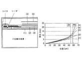
本実施形態に適用される磁気ヘッド16は,ディスク12の表面,リーダ及びライタの間に空気軸受表面を生成させる構造を有し,空気軸受表面を生成させる構造物を加熱させるヒータを備える。ヒータは,コイルで製作できる。図2に示したように,ヒータ用のコイルの位置Zを(1)〜(5)に変更させつつヒータ用のコイルに電流を印加して,磁気ヘッドの空気軸受表面が膨脹されるのを測定して最適の膨脹条件を有する位置を決定する。グラフで,リーダ位置SVとライタ位置RGとの間で比較的均一に膨脹される位置1にヒータ用のコイルを設置する。
The
図3に示したように,本実施形態にかかるディスクドライブは,ディスク12,磁気ヘッド16,プリアンプ210,書き込み/読み取りチャンネル220,バッファ230,コントローラ240,ROM(Read Only Memory)250A,RAM(Random Access Memory)250B,ホストインターフェース260,VCM駆動部270及びヒータ電流供給回路280を備える。
As shown in FIG. 3, the disk drive according to this embodiment includes the
ROM250Aには,ディスクドライブを制御するファームウェア及び制御情報が記憶されており,RAM250Bには,ドライブ駆動初期にROM250Aまたはディスク12から読み取ったディスクドライブの駆動に必要な情報が記憶される。
The
コントローラ240は,ホストインターフェース260を通じてホスト機器から受信される命令を分析し,分析された結果に相応する制御を実行する。コントローラ240は,VCMの励起及び磁気ヘッド16の移動を制御するためにVCM駆動部270に制御信号を供給する。
The
まず,一般的なディスクドライブの動作を説明すれば,次の通りである。 First, the operation of a general disk drive is described as follows.
データ読み取りモードで,ディスクドライブは,ディスク12から磁気ヘッド16の読み取り用の変換器により感知された電気的な信号をプリアンプ210で一次的に増幅させる。次いで,書き込み/読み取りチャンネル220では,自動利得制御回路(図示せず)により利得を制御してプリアンプ210で増幅された信号を一定なレベルに増幅させ,自動利得制御回路により一定なレベルに増幅されたアナログ信号をホスト機器(図示せず)が読み取り可能なデジタル信号に符号化させ,ストリームデータに変換してバッファ230に一時記憶させた後で,ホストインターフェース260を通じてホスト機器へ伝送する。
In the data reading mode, the disk drive primarily amplifies the electrical signal sensed by the transducer for reading the
次に,書き込みモードで,ディスクドライブは,ホストインターフェース260を通じてホスト機器からデータを入力されてバッファ230に一時記憶させた後で,バッファ230に記憶されたデータを順次に出力して,書き込み/読み取りチャンネル220により書き込みチャンネルに適したバイナリデータストリームに変換させた後,プリアンプ210により増幅された書き込み電流を磁気ヘッド16の書き込み用の変換器を通じてディスク12に記録させる。
Next, in the write mode, the disk drive receives data from the host device through the
書き込み/読み取りチャンネル220は,サーボフィールドに記録されたプリアンブル,SAM/SIM,グレーコード及びバースト信号を再生しつつ,トラックシーク及びトラック追従制御に必要な情報をコントローラ240に提供する。特に,書き込み/読み取りチャンネル220は,プリアンブル信号で自動利得制御回路のサーボ利得値を決定する。
The write /
ヒータ電流供給回路280は,磁気ヘッド16に内蔵されたヒータに電流を供給する。ヒータに供給する電流は,書き込みモード及び読み取りモードでそれぞれ異なる値に設定され,書き込みモード及び読み取りモードでディスク12と磁気ヘッド16との間隔を一致させるように決定される。
The heater
次いで,書き込みモード及び読み取りモードでヒータに供給する電流を決定する方法について説明する。 Next, a method for determining the current supplied to the heater in the writing mode and the reading mode will be described.
まず,読み取りモードで,磁気ヘッド16の飛行高さを調整するために磁気ヘッド16のヒータに供給する電流を決定する方法について,図4のフローチャートを中心に説明する。
First, a method of determining the current supplied to the heater of the
磁気ヘッド16をディスク上のテストトラックに移動させるためのシーク制御を実行する(S401)。
The seek control for moving the
次に,テストトラックでの線速度を測定する(S402)。線速度は,サーボセクタが検出される時間間隔を検出して,サーボセクタ間隔の長さを時間間隔に分ければ得ることができる。 Next, the linear velocity on the test track is measured (S402). The linear velocity can be obtained by detecting the time interval at which the servo sector is detected and dividing the length of the servo sector interval into time intervals.
次いで,テストトラックでデータ読み取りモードを実行する(S403)。 Next, the data reading mode is executed on the test track (S403).
データ読み取りモードを実行しつつ,一定時間後にヒータ電流供給回路280で初期値として磁気ヘッド16のヒータに供給される電流を0に設定して,ヒータの消費電力PWRを0に決定する(S404)。
While executing the data reading mode, the heater
次いで,書き込み/読み取りチャンネル220の自動利得制御回路(AGC)のAGC利得値を測定する(S405)。自動利得制御回路の利得値は,データフィールドを再生しつつ設定されたAGC利得値またはサーボフィールドを再生しつつ設定されたAGC利得値を意味する。本発明の一実施形態では,サーボAGC利得値TAAを利用する。
Next, the AGC gain value of the automatic gain control circuit (AGC) of the write /
AGC利得値を測定した後で,磁気ヘッド16がディスク12に接触されるかを判定する(S406)。磁気ヘッド16がディスク12に接触されるかは,位置エラー信号をモニタリングして位置エラー信号のレベルが臨界値を超える場合に,磁気ヘッド16がディスク12に接触されると判定する。
After measuring the AGC gain value, it is determined whether the
ステップS406の判定結果,磁気ヘッド16がディスク12に接触されていない場合には,ヒータ電流供給回路280で磁気ヘッド16のヒータに供給される電流を一定値ほど高めて,消費電力PWRをΔPほど増加させた後でステップS405を再び実行する(S408)。もちろん,この場合にも,ヒータの消費電力を増加させてから一定時間経過後にAGC利得を測定する。
If the result of determination in step S406 is that the
ステップS406の判定結果,磁気ヘッド16がディスク12に接触された場合には,ウォレス空間損失方程式を利用して,ヒータの消費電力PWRの変化に対するディスク12上での磁気ヘッド16の飛行高さグラフを次のように算出する(S408)。
As a result of the determination in step S406, when the
ウォレス空間損失方程式は,数式1のようである。 The Wallace space loss equation is as follows:
Δd=(λ/2π)×Ls・・・(数式1)
ここで,Δd=ディスクと磁気ヘッドとの磁気空間の変化量,λ=記録波長=線速度/記録周波数,Ls=Ln(TAA1/TAA2)であり,TAA1は以前のAGC利得値であり,TAA2は現在のAGC利得値である。
Δd = (λ / 2π) × Ls (Equation 1)
Here, Δd = change amount of the magnetic space between the disk and the magnetic head, λ = recording wavelength = linear velocity / recording frequency, Ls = Ln (TAA1 / TAA2), TAA1 is the previous AGC gain value, and TAA2 Is the current AGC gain value.
したがって,数式1を利用して,AGC利得値の変化に対するディスクと磁気ヘッドとの磁気空間の変化量を求めることができる。しかし,ヒータの消費電力PWRの変化によるAGC利得値を測定したので,消費電力の変化によるディスクと磁気ヘッドとの磁気空間の変化量を求めることができる。これにより,図6に示したような読み取りモードで,ヒータパワーの変化に対するヘッドの飛行高さに該当する空間利得のグラフを得ることができる。
Therefore, using
最終的に,図6のグラフから,読み取りモードで目標とするヘッドの飛行高さに対応するヒータの消費電力PWR値を決定し,決定された消費電力PWRによって読み取りモードで磁気ヘッド16のヒータに供給する電流値を決定する(S409)。
Finally, the power consumption PWR value of the heater corresponding to the target flying height of the head is determined from the graph of FIG. 6, and the heater P of the
次に,書き込みモードで,磁気ヘッド16の飛行高さを調整するために磁気ヘッド16のヒータに供給する電流を決定する方法について,図5のフローチャートを中心に説明する。
Next, a method for determining the current supplied to the heater of the
磁気ヘッド16をディスク上のテストトラックに移動させるためのシーク制御を実行する(S501)。
The seek control for moving the
次に,テストトラックでの線速度を測定する(S502)。線速度は,サーボセクタが検出される時間間隔を検出して,サーボセクタ間隔の長さを時間間隔に分ければ得ることができる。 Next, the linear velocity on the test track is measured (S502). The linear velocity can be obtained by detecting the time interval at which the servo sector is detected and dividing the length of the servo sector interval into time intervals.
書き込みモード及び読み取りモードでテストトラックを同一に設定する場合には,ステップS502を省略し,読み取りモードで測定した線速度を利用する。 When setting the same test track in the writing mode and the reading mode, step S502 is omitted and the linear velocity measured in the reading mode is used.
次いで,テストトラックでデータ書き込みモードを実行する(S503)。 Next, the data write mode is executed on the test track (S503).
データ書き込みモードを実行しつつ,一定時間後にヒータ電流供給回路280で初期値として磁気ヘッド16のヒータに供給される電流を0に設定して,ヒータの消費電力PWRを0に決定する(S504)。
While executing the data write mode, the heater
次いで,書き込み/読み取りチャンネル220の自動利得制御回路のAGC利得値を測定する(S505)。自動利得制御回路の利得値は,サーボフィールドを再生しつつ設定されたサーボAGC利得値TAAを意味する。
Next, the AGC gain value of the automatic gain control circuit of the write /
AGC利得値を測定した後で,磁気ヘッド16がディスク12に接触されるかを判定する(S506)。磁気ヘッド16がディスク12に接触されるかは,位置エラー信号をモニタリングして位置エラー信号のレベルが臨界値を超える場合に,磁気ヘッド16がディスク12に接触されると判定する。
After measuring the AGC gain value, it is determined whether the
ステップS506の判定結果,磁気ヘッド16がディスク12に接触されていない場合には,ヒータ電流供給回路280で磁気ヘッド16のヒータに供給される電流を一定値ほど高めて,消費電力PWRをΔPほど増加させた後でステップS505を再び実行する(S508)。もちろん,この場合にも,ヒータの消費電力を増加させてから一定時間経過後にAGC利得を算出する。
If the result of determination in step S506 is that the
ステップS506の判定結果,磁気ヘッド16がディスク12に接触された場合には,数式1のウォレス空間損失方程式を利用して,ヒータの消費電力PWRの変化に対するディスク12上での磁気ヘッド16の飛行高さグラフを算出する(S508)。
If the
読み取りモードで説明したような方式で,図6に示したような書き込みモードで,ヒータパワーの変化に対するヘッドの飛行高さに該当する空間利得のグラフを得ることができる。 With the method described in the reading mode, a graph of the spatial gain corresponding to the flying height of the head with respect to the change of the heater power can be obtained in the writing mode as shown in FIG.
最終的に,図6のグラフから,読み取りモードと同じ目標のヘッドの飛行高さに対応するヒータの消費電力PWR値を決定し,決定された消費電力PWRによって書き込みモードで磁気ヘッド16のヒータに供給する電流値を決定する(S509)。
Finally, the power consumption PWR value of the heater corresponding to the flying height of the target head that is the same as that in the reading mode is determined from the graph of FIG. 6, and the heater of the
このように読み取りモード及び書き込みモードで,それぞれ決定された磁気ヘッド16のヒータに供給する電流値に相応する電流をヒータ電流供給回路280で生成させてヒータに印加することによって,読み取りモード及び書き込みモードでディスク12と磁気ヘッド16との間隔を同一に調整できる。
In this manner, in the read mode and the write mode, the current corresponding to the current value supplied to the heater of the
すなわち,磁気ヘッド16のヒータに電流を供給しない場合には,図7Aに示したように,読み取りモード及び書き込みモードでディスク12上での磁気ヘッド16の飛行高さに差が発生したが,図4及び図5のフローチャートによりそれぞれ決定された読み取りモード及び書き込みモードでのヒータ電流をヒータ電流供給回路280で発生させる場合には(すなわち,FOD(Flying on Demand)電圧を発生させた場合),図7Bに示したように,読み取りモード及び書き込みモードでディスク12上での磁気ヘッド16の飛行高さを一致させることができる。
That is, when no current is supplied to the heater of the
本実施形態は,方法,装置,システムなどとして実行されうる。ソフトウェアで実行されるとき,本実施形態の構成手段は,必然的に必要な作業を実行するコードセグメントである。プログラムまたはコードセグメントは,プロセッサで読み取り可能な媒体に記憶され,または伝送媒体または通信網で搬送波と結合されたコンピュータデータ信号により伝送されうる。プロセッサで読み取り可能な媒体は,情報を記憶または伝送できるいかなる媒体も含む。プロセッサで読み取り可能な媒体の例としては,電子回路,半導体メモリ素子,ROM,フラッシュメモリ,EROM(Erasable ROM),フロッピー(登録商標)ディスク,光ディスク,ハードディスク,光ファイバ媒体,無線周波数(RF)網などがある。コンピュータデータ信号は,電子網チャンネル,光ファイバ,空気,電子系,RF網のような伝送媒体上に伝播可能ないかなる信号も含まれる。 The present embodiment can be implemented as a method, apparatus, system, or the like. When executed by software, the configuration means of the present embodiment is a code segment that inevitably performs necessary work. The program or code segment can be stored in a processor readable medium or transmitted by a computer data signal combined with a carrier wave in a transmission medium or communication network. The processor readable medium includes any medium that can store or transmit information. Examples of media readable by the processor include electronic circuits, semiconductor memory devices, ROM, flash memory, EROM (Erasable ROM), floppy (registered trademark) disks, optical disks, hard disks, optical fiber media, and radio frequency (RF) networks. and so on. Computer data signals include any signal that can propagate over a transmission medium such as electronic network channels, optical fibers, air, electronic systems, RF networks.
以上,添付図面を参照しながら本発明の好適な実施形態について説明したが,本発明はかかる例に限定されない。当業者であれば,特許請求の範囲に記載された技術的思想の範疇内において各種の変更例または修正例に想到し得ることは明らかであり,それらについても当然に本発明の技術的範囲に属するものと了解される。すなわち,添付された図面に図示して説明した特定の実施形態は,単に本発明の例として理解され,本発明の範囲を限定するものではなく,本発明が属する技術分野で本発明に記述された技術的思想の範囲でも多様な他の変更が発生しうるので,本発明は,示されるか,または記述された特定の構成及び配列に制限されないということは自明である。すなわち,本発明は,HDDを含む各種のディスクドライブに適用できるだけでなく,多様な種類のデータ記憶装置に適用できることは当然な事実である。 As mentioned above, although preferred embodiment of this invention was described referring an accompanying drawing, this invention is not limited to this example. It will be obvious to those skilled in the art that various changes or modifications can be conceived within the scope of the technical idea described in the claims, and these are naturally within the technical scope of the present invention. It is understood that it belongs. That is, the specific embodiments illustrated and described in the accompanying drawings are to be understood merely as examples of the present invention and are not intended to limit the scope of the present invention, but are described in the technical field to which the present invention belongs. Obviously, the invention is not limited to the specific arrangements and arrangements shown or described, since various other modifications may occur within the scope of the technical idea. That is, the present invention can be applied not only to various disk drives including HDDs but also to various types of data storage devices.
本発明は,ディスクドライブ関連の技術分野に適用可能である。 The present invention is applicable to a technical field related to a disk drive.
12 磁気ディスク
16 磁気ヘッド
26 ボイスコイル
210 プリアンプ
220 書き込み/読み取りチャンネル
230 バッファ
240 コントローラ
250A ROM
250B RAM
260 ホストインターフェース
270 VCM駆動部
280 ヒータ電流供給回路
12
250B RAM
260
Claims (5)
情報を記憶するディスクと,
前記ディスク上の磁界を感知する磁気読み取り素子及び前記ディスクを磁化させる磁気書き込み素子を備え,前記ディスクの表面,前記磁気読み取り素子及び前記磁気書き込み素子の間に空気軸受表面を生成させる構造を有し,前記空気軸受表面を生成させる構造物を加熱させるヒータを備える磁気ヘッドと,
書き込みモード及び読み取りモードでそれぞれ決定された電流を前記ヒータに印加する電流供給回路と,
を備え,
前記ヒータの消費電力の変化に対する前記ディスクと前記磁気ヘッドとの間隔のグラフであって,前記書き込みモード及び前記読み取りモードでそれぞれ算出された前記グラフに基づいて,前記書き込みモード及び前記読み取りモードにおいて前記ディスクと前記磁気ヘッドとの間隔が同一となるように前記ヒータに印加される電流値が決定され,
前記グラフは、
所定のテストトラックで線速度及び記録周波数を検出し、
前記テストトラックでデータ読み取りモード又はデータ書き込みモードを実行し、
前記磁気ヘッドと前記ディスクとが接触されるまで,前記ヒータに印加される電流を所定単位で増加させつつ再生される信号に対する自動利得制御回路の利得値を検出し、
前記ヒータの消費電力の変化に対する前記ディスクと前記磁気ヘッドとの間隔の前記グラフを次の数式に基づいて算出する
Δd=(λ/2π)×Ls
(ここで,Δd=ディスクと磁気ヘッドとの磁気空間の変化量,λ=記録波長=線速度/記録周波数,Ls=Ln(TAA1/TAA2)であり,TAA1は以前のAGC利得値であり,TAA2は現在のAGC利得値である)
ことにより算出される、
ことを特徴とする磁気ヘッド制御装置。 In a magnetic head controller of a data storage device,
A disk for storing information;
A magnetic reading element for sensing a magnetic field on the disk; and a magnetic writing element for magnetizing the disk; and a structure for generating an air bearing surface between the surface of the disk, the magnetic reading element, and the magnetic writing element. , A magnetic head comprising a heater for heating the structure for generating the air bearing surface;
A current supply circuit for applying currents respectively determined in a writing mode and a reading mode to the heater;
With
A graph of the distance between the disk and the magnetic head with respect to a change in power consumption of the heater, and based on the graph calculated in the write mode and the read mode, respectively, in the write mode and the read mode. The current value applied to the heater is determined so that the distance between the disk and the magnetic head is the same ,
The graph is
Detect linear velocity and recording frequency in a predetermined test track,
Performing a data reading mode or a data writing mode on the test track;
Detecting a gain value of an automatic gain control circuit for a signal reproduced while increasing a current applied to the heater in a predetermined unit until the magnetic head and the disk are brought into contact with each other;
The graph of the distance between the disk and the magnetic head with respect to the change in power consumption of the heater is calculated based on the following formula:
Δd = (λ / 2π) × Ls
(Where Δd = change amount of magnetic space between the disk and the magnetic head, λ = recording wavelength = linear velocity / recording frequency, Ls = Ln (TAA1 / TAA2), TAA1 is the previous AGC gain value, TAA2 is the current AGC gain value)
Calculated by
A magnetic head control device.
書き込みモード及び読み取りモードでそれぞれ前記ヒータに印加される電流を可変させつつ,前記ヒータの消費電力の変化に対するディスクと前記磁気ヘッドとの間隔のグラフを算出するステップと,
前記グラフに基づいて,書き込みモード及び読み取りモードにおいて前記ディスクと前記磁気ヘッドとの間隔が同一となるように前記ヒータに印加される電流値をそれぞれ決定するステップと,
前記書き込みモードについて決定された電流値を前記書き込みモードにおいて前記ヒータに印加するステップと,
前記読み取りモードについて決定された電流値を前記読み取りモードにおいて前記ヒータに印加するステップと,
を含み、
前記読み取りモード及び読み取りモードでそれぞれ,前記ヒータの消費電力の変化に対する前記ディスクと前記磁気ヘッドとの間隔の前記グラフを算出する前記ステップは,
所定のテストトラックで線速度及び記録周波数を検出するステップと,
前記テストトラックでデータ読み取りモード又はデータ書き込みモードを実行するステップと,
前記磁気ヘッドと前記ディスクとが接触されるまで,前記ヒータに印加される電流を所定単位で増加させつつ再生される信号に対する自動利得制御回路の利得値を検出するステップと,
前記ヒータの消費電力の変化に対する前記ディスクと前記磁気ヘッドとの間隔の前記グラフを次の数式に基づいて算出するステップと,
Δd=(λ/2π)×Ls
(ここで,Δd=ディスクと磁気ヘッドとの磁気空間の変化量,λ=記録波長=線速度/記録周波数,Ls=Ln(TAA1/TAA2)であり,TAA1は以前のAGC利得値であり,TAA2は現在のAGC利得値である)
を含む、
ことを特徴とする,磁気ヘッド制御方法。 In a magnetic head control method for a data storage device comprising a magnetic head with a built-in heater and a current supply circuit for applying a current to the heater,
Calculating a graph of an interval between the disk and the magnetic head with respect to a change in power consumption of the heater while varying a current applied to the heater in each of a writing mode and a reading mode;
Determining a current value to be applied to the heater based on the graph so that the distance between the disk and the magnetic head is the same in the write mode and the read mode;
Applying a current value determined for the write mode to the heater in the write mode;
Applying a current value determined for the reading mode to the heater in the reading mode;
Only including,
The step of calculating the graph of the distance between the disk and the magnetic head with respect to a change in power consumption of the heater in the reading mode and the reading mode, respectively,
Detecting linear velocity and recording frequency in a predetermined test track;
Executing a data read mode or a data write mode on the test track;
Detecting a gain value of an automatic gain control circuit for a signal reproduced while increasing a current applied to the heater in a predetermined unit until the magnetic head and the disk are brought into contact with each other;
Calculating the graph of the distance between the disk and the magnetic head with respect to a change in power consumption of the heater based on the following equation:
Δd = (λ / 2π) × Ls
(Where Δd = change amount of magnetic space between the disk and the magnetic head, λ = recording wavelength = linear velocity / recording frequency, Ls = Ln (TAA1 / TAA2), TAA1 is the previous AGC gain value, TAA2 is the current AGC gain value)
including,
A magnetic head control method.
書き込みモード及び読み取りモードでそれぞれ前記ヒータに印加される電流を可変させつつ,前記ヒータの消費電力の変化に対するディスクと前記磁気ヘッドとの間隔のグラフを算出するプロセスと,
前記グラフに基づいて,書き込みモード及び読み取りモードにおいて前記ディスクと前記磁気ヘッドとの間隔が同一となるように前記ヒータに印加される電流値をそれぞれ決定するプロセスと,
前記書き込みモードについて決定された電流値を前記書き込みモードにおいて前記ヒータに印加させるプロセスと,
前記読み取りモードについて決定された電流値を前記読み取りモードにおいて前記ヒータに印加させるプロセスと,
を前記コンピュータに実行させ、
前記グラフを算出するプロセスは、
所定のテストトラックで線速度及び記録周波数を検出するプロセスと,
前記テストトラックでデータ読み取りモード又はデータ書き込みモードを実行するプロセスと,
前記磁気ヘッドと前記ディスクとが接触されるまで,前記ヒータに印加される電流を所定単位で増加させつつ再生される信号に対する自動利得制御回路の利得値を検出するプロセスと,
前記ヒータの消費電力の変化に対する前記ディスクと前記磁気ヘッドとの間隔の前記グラフを次の数式に基づいて算出するプロセスと,
Δd=(λ/2π)×Ls
(ここで,Δd=ディスクと磁気ヘッドとの磁気空間の変化量,λ=記録波長=線速度/記録周波数,Ls=Ln(TAA1/TAA2)であり,TAA1は以前のAGC利得値であり,TAA2は現在のAGC利得値である)
を含む、
ことを特徴とする,記録媒体。
In a recording medium including a computer-readable code for executing a magnetic head control method of a data storage device comprising a magnetic head with a built-in heater and a current supply circuit for applying a current to the heater,
A process of calculating a graph of a distance between the disk and the magnetic head with respect to a change in power consumption of the heater while varying a current applied to the heater in each of a writing mode and a reading mode;
Based on the graph, a process for determining a current value applied to the heater so that the distance between the disk and the magnetic head is the same in the write mode and the read mode;
A process of applying a current value determined for the write mode to the heater in the write mode;
A process of applying a current value determined for the reading mode to the heater in the reading mode;
To the computer ,
The process of calculating the graph is as follows:
A process for detecting linear velocity and recording frequency in a given test track;
A process of executing a data read mode or a data write mode on the test track;
Detecting a gain value of an automatic gain control circuit for a signal to be reproduced while increasing a current applied to the heater in a predetermined unit until the magnetic head and the disk are brought into contact with each other;
A process of calculating the graph of the distance between the disk and the magnetic head with respect to a change in power consumption of the heater based on the following equation:
Δd = (λ / 2π) × Ls
(Where Δd = change amount of magnetic space between the disk and the magnetic head, λ = recording wavelength = linear velocity / recording frequency, Ls = Ln (TAA1 / TAA2), TAA1 is the previous AGC gain value, TAA2 is the current AGC gain value)
including,
A recording medium characterized by that.
Applications Claiming Priority (2)
| Application Number | Priority Date | Filing Date | Title |
|---|---|---|---|
| KR10-2004-0113692 | 2004-12-28 | ||
| KR1020040113692A KR100640621B1 (en) | 2004-12-28 | 2004-12-28 | Apparatus and method for adjusting a flying height of magnetic head in disk drive |
Publications (3)
| Publication Number | Publication Date |
|---|---|
| JP2006190454A JP2006190454A (en) | 2006-07-20 |
| JP2006190454A5 JP2006190454A5 (en) | 2009-01-29 |
| JP5032768B2 true JP5032768B2 (en) | 2012-09-26 |
Family
ID=36096155
Family Applications (1)
| Application Number | Title | Priority Date | Filing Date |
|---|---|---|---|
| JP2005376053A Expired - Fee Related JP5032768B2 (en) | 2004-12-28 | 2005-12-27 | Magnetic head control device, magnetic head control method, and recording medium |
Country Status (5)
| Country | Link |
|---|---|
| US (1) | US7649706B2 (en) |
| EP (1) | EP1677290B1 (en) |
| JP (1) | JP5032768B2 (en) |
| KR (1) | KR100640621B1 (en) |
| DE (1) | DE602005014077D1 (en) |
Families Citing this family (42)
| Publication number | Priority date | Publication date | Assignee | Title |
|---|---|---|---|---|
| US7180692B1 (en) * | 2005-12-27 | 2007-02-20 | Hitachi Global Storage Technologies Netherlands B.V. | System and method for calibrating and controlling a fly-height actuator in a magnetic recording disk drive |
| US7423829B2 (en) * | 2006-03-22 | 2008-09-09 | Samsung Electronics Co., Ltd. | Circuit for flying height on demand |
| JP4379814B2 (en) | 2006-03-28 | 2009-12-09 | 富士通株式会社 | Storage device, control method, control device, and program |
| JP4439483B2 (en) | 2006-03-28 | 2010-03-24 | 東芝ストレージデバイス株式会社 | Storage device, control device, control method, and program |
| US7633696B2 (en) * | 2006-03-29 | 2009-12-15 | Seagate Technology Llc | Fly height calibration for read/write heads |
| US20070230021A1 (en) * | 2006-03-29 | 2007-10-04 | Maxtor Corporation | Flying height control for read-to-write and write-to-read transitions |
| KR100761841B1 (en) * | 2006-04-04 | 2007-09-28 | 삼성전자주식회사 | Apparatus and method for controlling a flying height of magnetic head in retry mode and disk drive using the same |
| US7423830B2 (en) * | 2006-04-10 | 2008-09-09 | Iomega Corporation | Detecting head/disk contact in a disk drive using a calibration parameter |
| JP2007310978A (en) * | 2006-05-19 | 2007-11-29 | Fujitsu Ltd | Method and apparatus for controlling floating amount of head, and storage device and program |
| JP2008041118A (en) * | 2006-08-01 | 2008-02-21 | Denso Corp | Memory device and on-board navigation system |
| JP4908106B2 (en) * | 2006-08-18 | 2012-04-04 | 東芝ストレージデバイス株式会社 | Storage device, control method, control device, and program |
| JP4728929B2 (en) * | 2006-10-31 | 2011-07-20 | 東芝ストレージデバイス株式会社 | Control device, control method, and storage device |
| JP2008112544A (en) * | 2006-10-31 | 2008-05-15 | Fujitsu Ltd | Head-controller, storage device, and head-controlling method |
| JP4675873B2 (en) * | 2006-11-27 | 2011-04-27 | 東芝ストレージデバイス株式会社 | Head control device, storage device, and upper limit power determination method |
| JP2008171520A (en) * | 2007-01-15 | 2008-07-24 | Fujitsu Ltd | Controller, control method, and storage device |
| KR100855973B1 (en) * | 2007-01-24 | 2008-09-02 | 삼성전자주식회사 | Hard disk drive for controlling flying height of head and the method using the hard disk drive |
| JP4795982B2 (en) * | 2007-01-31 | 2011-10-19 | ヒタチグローバルストレージテクノロジーズネザーランドビーブイ | Disk drive device, altitude determination method thereof, and characteristic determination method of head element portion thereof |
| JP2008192187A (en) * | 2007-01-31 | 2008-08-21 | Fujitsu Ltd | Head controller, memory device, and contact detection method |
| JP4805860B2 (en) * | 2007-02-05 | 2011-11-02 | 東芝ストレージデバイス株式会社 | Flying height measuring device, storage device, and flying height measuring method |
| JP2008243288A (en) * | 2007-03-27 | 2008-10-09 | Fujitsu Ltd | Magnetic storage device, control apparatus and flying height control method |
| KR20080090011A (en) | 2007-04-03 | 2008-10-08 | 삼성전자주식회사 | Hard disk drive for improving instability of head at low temperature and method using the hard disk drive |
| JP2008310904A (en) | 2007-06-15 | 2008-12-25 | Fujitsu Ltd | Control apparatus, storage apparatus, program for determining heater set value, and method of manufacturing storage apparatus |
| JP4840780B2 (en) | 2007-06-19 | 2011-12-21 | 東芝ストレージデバイス株式会社 | Head IC of storage device and storage device using the same |
| US7508617B1 (en) * | 2007-09-07 | 2009-03-24 | Seagate Technology Llc | Fly height compensation using read gain control loop |
| US7616398B2 (en) * | 2007-11-09 | 2009-11-10 | Hitachi Global Storage Technologies Netherlands B.V. | Fly height adjustment device calibration |
| EP2065888A1 (en) | 2007-11-30 | 2009-06-03 | Hitachi Global Storage Technologies Netherlands B.V. | Disk drive device and clearence control method thereof |
| JP4909878B2 (en) * | 2007-11-30 | 2012-04-04 | ヒタチグローバルストレージテクノロジーズネザーランドビーブイ | Disk drive device and clearance adjustment method thereof |
| JP4854038B2 (en) * | 2008-03-26 | 2012-01-11 | 東芝ストレージデバイス株式会社 | Information access apparatus and flying height control method |
| JP2010033665A (en) * | 2008-07-30 | 2010-02-12 | Toshiba Storage Device Corp | Magnetic storage device and control method of supply power for controlling floating height of magnetic head |
| US7990641B2 (en) * | 2008-08-06 | 2011-08-02 | Kabushiki Kaisha Toshiba | Proximity detection method for magnetic head and recording medium |
| JP5080411B2 (en) * | 2008-09-19 | 2012-11-21 | エイチジーエスティーネザーランドビーブイ | Method for adjusting common potential of elements on disk drive and head slider |
| JP4836284B2 (en) | 2008-09-30 | 2011-12-14 | 東芝ストレージデバイス株式会社 | Control device, control method, and information storage device |
| US20100157765A1 (en) * | 2008-12-19 | 2010-06-24 | Seagate Technology Llc | Collection of readback signal modulation data |
| KR101592195B1 (en) * | 2010-03-26 | 2016-02-05 | 시게이트 테크놀로지 인터내셔날 | Method and apparatus for detecting touch-down and contact of head/media using sensor and disk drive and storage media applying the same |
| US8730611B2 (en) * | 2011-02-28 | 2014-05-20 | Seagate Technology Llc | Contact detection |
| JP5830890B2 (en) | 2011-03-24 | 2015-12-09 | 富士電機株式会社 | Magnetic disk device, magnetic disk and manufacturing method thereof |
| US8687313B2 (en) * | 2011-06-23 | 2014-04-01 | Western Digital Technologies, Inc. | Disk drive mapping out data tracks to avoid thermal asperities |
| US8982502B2 (en) * | 2011-12-12 | 2015-03-17 | HGST Netherlands B.V. | Hard disk drive with write assist based on detected conditions |
| US8995076B1 (en) * | 2014-04-21 | 2015-03-31 | Seagate Technology Llc | Head-medium contact detection using electromagnetic attraction |
| US9472225B2 (en) * | 2015-02-11 | 2016-10-18 | Seagate Technology Llc | Heat-assisted magnetic recording head-disk clearance setting |
| US9548072B2 (en) | 2015-02-11 | 2017-01-17 | Seagate Technology Llc | Concurrent modulation and frictional heating head disk contact detection |
| US9990950B1 (en) | 2017-07-17 | 2018-06-05 | Seagate Technology Llc | Calibration and adjusting target pre-write clearance offset for a heat-assisted magnetic recording device |
Family Cites Families (18)
| Publication number | Priority date | Publication date | Assignee | Title |
|---|---|---|---|---|
| US4777544A (en) * | 1986-08-15 | 1988-10-11 | International Business Machine Corporation | Method and apparatus for in-situ measurement of head/recording medium clearance |
| US5959801A (en) | 1997-10-22 | 1999-09-28 | International Business Machines Corporation | Stiction reduction in disk drives using heating |
| JP2000348456A (en) | 1999-06-07 | 2000-12-15 | Minolta Co Ltd | Information recording/reproducing apparatus |
| US6963464B2 (en) | 2000-10-26 | 2005-11-08 | Hitachi Global Storage Technologies Japan, Ltd. | Magnetic head heating element in a disk drive |
| US20020114108A1 (en) | 2001-02-19 | 2002-08-22 | Seagate Technology Llc | Apparatus and method for passive adaptive flying height control in a disc drive |
| US6760182B2 (en) | 2001-02-19 | 2004-07-06 | Seagate Technology Llc | Temperature compensated fly height control |
| JP3636133B2 (en) | 2001-11-29 | 2005-04-06 | Tdk株式会社 | Thin film magnetic head, head gimbal assembly including the thin film magnetic head, and magnetic disk apparatus including the head gimbal assembly |
| US20030111856A1 (en) * | 2001-12-13 | 2003-06-19 | Hewett Frank W. | Bundling, carrying and storing device |
| JP2003272335A (en) * | 2002-03-13 | 2003-09-26 | Toshiba Corp | Magnetic disk device |
| JP2003308670A (en) * | 2002-04-12 | 2003-10-31 | Hitachi Ltd | Magnetic disk unit |
| US7089649B2 (en) | 2002-09-26 | 2006-08-15 | Samsung Electronics Co. Ltd, | Method of estimating a thermal pole tip protrusion for a head gimbal assembly |
| JP4076434B2 (en) | 2002-12-12 | 2008-04-16 | 株式会社日立グローバルストレージテクノロジーズ | Magnetic head and head gimbal assembly |
| KR100468779B1 (en) | 2002-12-13 | 2005-01-29 | 삼성전자주식회사 | Method for measuring TPTP of a magnetic head and a method for controlling write current thereof |
| US6972919B2 (en) * | 2003-09-05 | 2005-12-06 | Hitachi Global Storage Technologies Netherlands, B.V. | Increasing head-disk interface reliability using controlled heating |
| US6975472B2 (en) * | 2003-09-12 | 2005-12-13 | Seagate Technology Llc | Head with heating element and control regime therefor |
| US7061706B2 (en) * | 2004-03-15 | 2006-06-13 | Hitachi Global Storage Technologies Netherlands B.V. | Circuitry for linear control of head flying height using thermal means |
| US7400473B1 (en) * | 2004-07-13 | 2008-07-15 | Maxtor Corporation | Slider with independent fly-height adjustment of reader and writer |
| JP4413168B2 (en) * | 2005-07-19 | 2010-02-10 | 東芝ストレージデバイス株式会社 | Heater control method and storage device |
-
2004
- 2004-12-28 KR KR1020040113692A patent/KR100640621B1/en not_active IP Right Cessation
-
2005
- 2005-12-27 JP JP2005376053A patent/JP5032768B2/en not_active Expired - Fee Related
- 2005-12-27 US US11/317,012 patent/US7649706B2/en active Active
- 2005-12-28 EP EP05028607A patent/EP1677290B1/en not_active Expired - Fee Related
- 2005-12-28 DE DE602005014077T patent/DE602005014077D1/en active Active
Also Published As
| Publication number | Publication date |
|---|---|
| US20060139789A1 (en) | 2006-06-29 |
| JP2006190454A (en) | 2006-07-20 |
| EP1677290A2 (en) | 2006-07-05 |
| EP1677290B1 (en) | 2009-04-22 |
| US7649706B2 (en) | 2010-01-19 |
| DE602005014077D1 (en) | 2009-06-04 |
| KR100640621B1 (en) | 2006-11-01 |
| EP1677290A3 (en) | 2006-09-27 |
| KR20060075126A (en) | 2006-07-04 |
Similar Documents
| Publication | Publication Date | Title |
|---|---|---|
| JP5032768B2 (en) | Magnetic head control device, magnetic head control method, and recording medium | |
| US7835104B2 (en) | Storage device, control method, control device, and program | |
| JP4728929B2 (en) | Control device, control method, and storage device | |
| US7426090B2 (en) | Storage device, control device, control method, and program | |
| JP5165445B2 (en) | Adaptive magnetic head flying height adjustment method, computer-readable recording medium storing a program for causing the computer to execute the method, and disk drive using the same | |
| US8537488B2 (en) | Method for specifying control value for controlling clearance adjustment amount between head and disk, disk drive device and manufacturing method thereof | |
| JP2008171520A (en) | Controller, control method, and storage device | |
| US7583467B2 (en) | Hard disk drive apparatus, method to control flying on demand of hard disk drive apparatus using thermal asperity signal, and recording media for computer program thereof | |
| JP4401693B2 (en) | Data storage system control method based on temperature, data storage system control device based on temperature, and warming light current determination method in data storage system | |
| JP2009157987A (en) | Method for adjusting recess depth of head slider and disk drive device | |
| US7852594B2 (en) | Device and method for specifying control value for controlling clearance between head and disk, and magnetic disk drive device | |
| JP4011049B2 (en) | Method for optimizing write characteristics of magnetic head, method for defining magnetic head, method for operating drive, and hard disk drive | |
| JP4895560B2 (en) | Data storage | |
| JP5052035B2 (en) | Control method of recording intensity of hard disk drive, recording medium, and hard disk drive | |
| JP5080841B2 (en) | Control device, control method, recording medium, and disk drive for flying height of magnetic head in retry mode | |
| CN111599384B (en) | Magnetic disk device and recording method for magnetic disk device | |
| EP1950741A2 (en) | Device for control of the flying height of magnetic head in a hard disk drive apparatus and a control method therefor | |
| KR20110000962A (en) | Method for controlling read or write of disk drive |
Legal Events
| Date | Code | Title | Description |
|---|---|---|---|
| A521 | Written amendment |
Free format text: JAPANESE INTERMEDIATE CODE: A523 Effective date: 20081208 |
|
| A621 | Written request for application examination |
Free format text: JAPANESE INTERMEDIATE CODE: A621 Effective date: 20081208 |
|
| A977 | Report on retrieval |
Free format text: JAPANESE INTERMEDIATE CODE: A971007 Effective date: 20110215 |
|
| A131 | Notification of reasons for refusal |
Free format text: JAPANESE INTERMEDIATE CODE: A131 Effective date: 20110322 |
|
| A521 | Written amendment |
Free format text: JAPANESE INTERMEDIATE CODE: A523 Effective date: 20110620 |
|
| RD03 | Notification of appointment of power of attorney |
Free format text: JAPANESE INTERMEDIATE CODE: A7423 Effective date: 20110620 |
|
| A02 | Decision of refusal |
Free format text: JAPANESE INTERMEDIATE CODE: A02 Effective date: 20120131 |
|
| A521 | Written amendment |
Free format text: JAPANESE INTERMEDIATE CODE: A523 Effective date: 20120531 |
|
| A911 | Transfer of reconsideration by examiner before appeal (zenchi) |
Free format text: JAPANESE INTERMEDIATE CODE: A911 Effective date: 20120608 |
|
| TRDD | Decision of grant or rejection written | ||
| A01 | Written decision to grant a patent or to grant a registration (utility model) |
Free format text: JAPANESE INTERMEDIATE CODE: A01 Effective date: 20120626 |
|
| A01 | Written decision to grant a patent or to grant a registration (utility model) |
Free format text: JAPANESE INTERMEDIATE CODE: A01 |
|
| A61 | First payment of annual fees (during grant procedure) |
Free format text: JAPANESE INTERMEDIATE CODE: A61 Effective date: 20120629 |
|
| R150 | Certificate of patent or registration of utility model |
Free format text: JAPANESE INTERMEDIATE CODE: R150 |
|
| FPAY | Renewal fee payment (event date is renewal date of database) |
Free format text: PAYMENT UNTIL: 20150706 Year of fee payment: 3 |
|
| LAPS | Cancellation because of no payment of annual fees |