JP5032762B2 - Electronics - Google Patents
Electronics Download PDFInfo
- Publication number
- JP5032762B2 JP5032762B2 JP2005317182A JP2005317182A JP5032762B2 JP 5032762 B2 JP5032762 B2 JP 5032762B2 JP 2005317182 A JP2005317182 A JP 2005317182A JP 2005317182 A JP2005317182 A JP 2005317182A JP 5032762 B2 JP5032762 B2 JP 5032762B2
- Authority
- JP
- Japan
- Prior art keywords
- electronic device
- battery check
- power supply
- started
- load
- Prior art date
- Legal status (The legal status is an assumption and is not a legal conclusion. Google has not performed a legal analysis and makes no representation as to the accuracy of the status listed.)
- Expired - Fee Related
Links
Images


Classifications
-
- H—ELECTRICITY
- H01—ELECTRIC ELEMENTS
- H01M—PROCESSES OR MEANS, e.g. BATTERIES, FOR THE DIRECT CONVERSION OF CHEMICAL ENERGY INTO ELECTRICAL ENERGY
- H01M8/00—Fuel cells; Manufacture thereof
- H01M8/04—Auxiliary arrangements, e.g. for control of pressure or for circulation of fluids
- H01M8/04298—Processes for controlling fuel cells or fuel cell systems
- H01M8/04313—Processes for controlling fuel cells or fuel cell systems characterised by the detection or assessment of variables; characterised by the detection or assessment of failure or abnormal function
- H01M8/04492—Humidity; Ambient humidity; Water content
- H01M8/04529—Humidity; Ambient humidity; Water content of the electrolyte
-
- H—ELECTRICITY
- H01—ELECTRIC ELEMENTS
- H01M—PROCESSES OR MEANS, e.g. BATTERIES, FOR THE DIRECT CONVERSION OF CHEMICAL ENERGY INTO ELECTRICAL ENERGY
- H01M8/00—Fuel cells; Manufacture thereof
- H01M8/04—Auxiliary arrangements, e.g. for control of pressure or for circulation of fluids
- H01M8/04082—Arrangements for control of reactant parameters, e.g. pressure or concentration
- H01M8/04089—Arrangements for control of reactant parameters, e.g. pressure or concentration of gaseous reactants
- H01M8/04119—Arrangements for control of reactant parameters, e.g. pressure or concentration of gaseous reactants with simultaneous supply or evacuation of electrolyte; Humidifying or dehumidifying
-
- H—ELECTRICITY
- H01—ELECTRIC ELEMENTS
- H01M—PROCESSES OR MEANS, e.g. BATTERIES, FOR THE DIRECT CONVERSION OF CHEMICAL ENERGY INTO ELECTRICAL ENERGY
- H01M8/00—Fuel cells; Manufacture thereof
- H01M8/04—Auxiliary arrangements, e.g. for control of pressure or for circulation of fluids
- H01M8/04223—Auxiliary arrangements, e.g. for control of pressure or for circulation of fluids during start-up or shut-down; Depolarisation or activation, e.g. purging; Means for short-circuiting defective fuel cells
- H01M8/04228—Auxiliary arrangements, e.g. for control of pressure or for circulation of fluids during start-up or shut-down; Depolarisation or activation, e.g. purging; Means for short-circuiting defective fuel cells during shut-down
-
- H—ELECTRICITY
- H01—ELECTRIC ELEMENTS
- H01M—PROCESSES OR MEANS, e.g. BATTERIES, FOR THE DIRECT CONVERSION OF CHEMICAL ENERGY INTO ELECTRICAL ENERGY
- H01M8/00—Fuel cells; Manufacture thereof
- H01M8/04—Auxiliary arrangements, e.g. for control of pressure or for circulation of fluids
- H01M8/04298—Processes for controlling fuel cells or fuel cell systems
- H01M8/043—Processes for controlling fuel cells or fuel cell systems applied during specific periods
- H01M8/04303—Processes for controlling fuel cells or fuel cell systems applied during specific periods applied during shut-down
-
- H—ELECTRICITY
- H01—ELECTRIC ELEMENTS
- H01M—PROCESSES OR MEANS, e.g. BATTERIES, FOR THE DIRECT CONVERSION OF CHEMICAL ENERGY INTO ELECTRICAL ENERGY
- H01M8/00—Fuel cells; Manufacture thereof
- H01M8/04—Auxiliary arrangements, e.g. for control of pressure or for circulation of fluids
- H01M8/04298—Processes for controlling fuel cells or fuel cell systems
- H01M8/04313—Processes for controlling fuel cells or fuel cell systems characterised by the detection or assessment of variables; characterised by the detection or assessment of failure or abnormal function
- H01M8/04537—Electric variables
- H01M8/04544—Voltage
- H01M8/04552—Voltage of the individual fuel cell
-
- H—ELECTRICITY
- H01—ELECTRIC ELEMENTS
- H01M—PROCESSES OR MEANS, e.g. BATTERIES, FOR THE DIRECT CONVERSION OF CHEMICAL ENERGY INTO ELECTRICAL ENERGY
- H01M8/00—Fuel cells; Manufacture thereof
- H01M8/04—Auxiliary arrangements, e.g. for control of pressure or for circulation of fluids
- H01M8/04298—Processes for controlling fuel cells or fuel cell systems
- H01M8/04313—Processes for controlling fuel cells or fuel cell systems characterised by the detection or assessment of variables; characterised by the detection or assessment of failure or abnormal function
- H01M8/04537—Electric variables
- H01M8/04544—Voltage
- H01M8/04559—Voltage of fuel cell stacks
-
- H—ELECTRICITY
- H01—ELECTRIC ELEMENTS
- H01M—PROCESSES OR MEANS, e.g. BATTERIES, FOR THE DIRECT CONVERSION OF CHEMICAL ENERGY INTO ELECTRICAL ENERGY
- H01M8/00—Fuel cells; Manufacture thereof
- H01M8/04—Auxiliary arrangements, e.g. for control of pressure or for circulation of fluids
- H01M8/04298—Processes for controlling fuel cells or fuel cell systems
- H01M8/04313—Processes for controlling fuel cells or fuel cell systems characterised by the detection or assessment of variables; characterised by the detection or assessment of failure or abnormal function
- H01M8/04664—Failure or abnormal function
- H01M8/04671—Failure or abnormal function of the individual fuel cell
-
- H—ELECTRICITY
- H01—ELECTRIC ELEMENTS
- H01M—PROCESSES OR MEANS, e.g. BATTERIES, FOR THE DIRECT CONVERSION OF CHEMICAL ENERGY INTO ELECTRICAL ENERGY
- H01M2250/00—Fuel cells for particular applications; Specific features of fuel cell system
- H01M2250/30—Fuel cells in portable systems, e.g. mobile phone, laptop
-
- Y—GENERAL TAGGING OF NEW TECHNOLOGICAL DEVELOPMENTS; GENERAL TAGGING OF CROSS-SECTIONAL TECHNOLOGIES SPANNING OVER SEVERAL SECTIONS OF THE IPC; TECHNICAL SUBJECTS COVERED BY FORMER USPC CROSS-REFERENCE ART COLLECTIONS [XRACs] AND DIGESTS
- Y02—TECHNOLOGIES OR APPLICATIONS FOR MITIGATION OR ADAPTATION AGAINST CLIMATE CHANGE
- Y02B—CLIMATE CHANGE MITIGATION TECHNOLOGIES RELATED TO BUILDINGS, e.g. HOUSING, HOUSE APPLIANCES OR RELATED END-USER APPLICATIONS
- Y02B90/00—Enabling technologies or technologies with a potential or indirect contribution to GHG emissions mitigation
- Y02B90/10—Applications of fuel cells in buildings
-
- Y—GENERAL TAGGING OF NEW TECHNOLOGICAL DEVELOPMENTS; GENERAL TAGGING OF CROSS-SECTIONAL TECHNOLOGIES SPANNING OVER SEVERAL SECTIONS OF THE IPC; TECHNICAL SUBJECTS COVERED BY FORMER USPC CROSS-REFERENCE ART COLLECTIONS [XRACs] AND DIGESTS
- Y02—TECHNOLOGIES OR APPLICATIONS FOR MITIGATION OR ADAPTATION AGAINST CLIMATE CHANGE
- Y02E—REDUCTION OF GREENHOUSE GAS [GHG] EMISSIONS, RELATED TO ENERGY GENERATION, TRANSMISSION OR DISTRIBUTION
- Y02E60/00—Enabling technologies; Technologies with a potential or indirect contribution to GHG emissions mitigation
- Y02E60/30—Hydrogen technology
- Y02E60/50—Fuel cells
Landscapes
- Chemical Kinetics & Catalysis (AREA)
- Engineering & Computer Science (AREA)
- Manufacturing & Machinery (AREA)
- Sustainable Development (AREA)
- Sustainable Energy (AREA)
- Chemical & Material Sciences (AREA)
- Life Sciences & Earth Sciences (AREA)
- Electrochemistry (AREA)
- General Chemical & Material Sciences (AREA)
- Fuel Cell (AREA)
- Studio Devices (AREA)
- Camera Bodies And Camera Details Or Accessories (AREA)
- Indication In Cameras, And Counting Of Exposures (AREA)
Description
本発明は、燃料電池を備えた電子機器に関する。 The present invention relates to an electronic device including a fuel cell.
電池による電力供給を受けて機能する様々な電子機器が存在している。その中でも、特に屋外使用が可能な電子機器における電力供給においては、電池寿命が大きな課題である。 There are various electronic devices that function by receiving power supply from batteries. Among them, battery life is a major issue particularly in power supply in electronic devices that can be used outdoors.
ここでは、屋外使用が可能な電子機器の代表としてカメラを取り上げて説明する。撮影レンズから入射する被写体像をCCD等の固体撮像素子により光電変換し、この光電変換した画像信号をA/D変換して記録媒体に記録し、更に内蔵の液晶モニタで画像の表示が可能なデジタルカメラが一般的に知られている。 Here, a camera will be described as a representative example of an electronic device that can be used outdoors. The subject image incident from the photographing lens is photoelectrically converted by a solid-state image sensor such as a CCD, and the photoelectrically converted image signal is A / D converted and recorded on a recording medium, and further, the image can be displayed on a built-in liquid crystal monitor. Digital cameras are generally known.
特に撮影レンズが交換可能なデジタル一眼レフカメラでは、銀塩フィルムカメラと同様に良好な操作性及び高速連写性能を有しつつ、撮影できる画像が高画質であること、撮影できる被写体輝度範囲が広いこと等が要求される。そのため、画素数が多く、かつ、感度の高い撮像素子の採用が必要である。更には銀塩フィルムカメラと比較すると、撮像回路、画像処理回路、画像表示回路等の多数の電気部品を使用した大規模な電気回路が付加されている。 In particular, digital SLR cameras with interchangeable photographic lenses have good operability and high-speed continuous shooting performance, as with silver-salt film cameras. It is required to be wide. For this reason, it is necessary to employ an image sensor having a large number of pixels and high sensitivity. Furthermore, compared with a silver salt film camera, a large-scale electric circuit using many electric parts such as an image pickup circuit, an image processing circuit, and an image display circuit is added.
その結果、デジタル一眼レフカメラでは消費電力が大きくなり、十分なエネルギーを供給できる電池が要求されている。一方で、カメラの小型化、軽量化が進む中、従来の一次電池や二次電池ではカメラの駆動に十分なエネルギーを供給することが困難となってきている。 As a result, the digital single-lens reflex camera has a large power consumption, and a battery capable of supplying sufficient energy is required. On the other hand, with the progress of miniaturization and weight reduction of cameras, it has become difficult to supply sufficient energy for driving the camera with conventional primary batteries and secondary batteries.
このような問題の解決策として、小型の燃料電池が注目されている。燃料電池は、従来の発電システムに比べて発電効率が高く、しかも廃棄物がクリーンである。さらには、体積当たり、重量当たりの供給エネルギー量が従来の電池に比べて数倍から十倍近くであることから、小型電子機器の電源として有用であると言われている。 As a solution to such a problem, a small fuel cell has attracted attention. Fuel cells have higher power generation efficiency than conventional power generation systems and clean waste. Furthermore, since the amount of energy supplied per unit volume and per unit weight is several to ten times that of conventional batteries, it is said to be useful as a power source for small electronic devices.
以下、燃料電池の発電の原理を説明する。燃料電池は、水素を含む燃料ガスを燃料極に供給し、酸素を含む酸素ガスを酸素極に供給して、両極で起こる電気化学反応によって起電力を得る。燃料極に供給される水素は、触媒によってプロトンと電子に分離される。分離した電子は外部回路を通って酸素極に移動し、プロトンは固体高分子膜(高分子電解質膜)を通って酸素極に移動する。酸素極ではプロトン、電子及び酸素が結合し、水と二酸化炭素が発生する。 Hereinafter, the principle of power generation of the fuel cell will be described. A fuel cell supplies a fuel gas containing hydrogen to a fuel electrode, supplies an oxygen gas containing oxygen to an oxygen electrode, and obtains an electromotive force by an electrochemical reaction occurring at both electrodes. Hydrogen supplied to the fuel electrode is separated into protons and electrons by the catalyst. The separated electrons move to the oxygen electrode through the external circuit, and the protons move to the oxygen electrode through the solid polymer membrane (polymer electrolyte membrane). At the oxygen electrode, protons, electrons and oxygen are combined to generate water and carbon dioxide.
燃料電池で起こる電気化学反応を示す。(1)式は燃料極における反応、(2)式は酸素極における反応、(3)式は電池全体で起こる反応を表わす。
H2 → 2H++2e- …(1)
(1/2)O2+2H++2e- → H2O …(2)
H2+(1/2)O2 → H2O …(3)
Fig. 2 shows an electrochemical reaction that occurs in a fuel cell. Equation (1) represents the reaction at the fuel electrode, Equation (2) represents the reaction at the oxygen electrode, and Equation (3) represents the reaction occurring in the entire battery.
H 2 → 2H + + 2e − (1)
(1/2) O 2 + 2H + + 2e − → H 2 O (2)
H 2 + (1/2) O 2 → H 2 O (3)
図16(a)は燃料電池の一例を示す平面図であり、図16(b)は正面図である。この燃料電池は、酸化剤として反応に用いる酸素を外気から取り入れるため、筐体70の上面、下面、及び長側面に外気を取り入れるための通気孔73が設けられている。この通気孔73は生成した水を水蒸気として逃がす作用、及び、反応により発生した熱を外に逃がす作用も奏する。また、筐体70の一方の短側面には電気を取り出すための電極72が設けられている。
FIG. 16A is a plan view showing an example of a fuel cell, and FIG. 16B is a front view. In this fuel cell, in order to take in oxygen used for the reaction as an oxidant from outside air, a
一方、筐体70の内部は、燃料極113と高分子電解質膜112と酸素極111と触媒からなるセルの1つ以上からなるセル部71、燃料を貯蔵する燃料タンク76、燃料タンク76と各セル部71とをつなぐ燃料供給路75、燃料の圧力を測定する圧力センサ77により構成されている。
On the other hand, the inside of the housing 70 includes a
このように構成される燃料電池セルは、起電力約0.8V、電流密度約300mA/cm2であり、例えば単位セルの大きさは1.2cm×2cm程度の大きさに設定される。この燃料電池セルを8枚直列につなぐと、電池全体の出力は約6.4V、720mAで約4.6Wとなる。図16においては、燃料電池セルは同面積の2枚が積層されたものを示しているが、積層枚数は上述のごとく多くの枚数を直列に接続することで、高電圧化を図ることができる。 The fuel cell configured as described above has an electromotive force of about 0.8 V and a current density of about 300 mA / cm 2. For example, the size of the unit cell is set to about 1.2 cm × 2 cm. When eight fuel cells are connected in series, the output of the entire battery is about 4.6 W at about 6.4 V and 720 mA. In FIG. 16, the fuel cells are shown in which two sheets having the same area are stacked. However, the number of stacked layers can be increased by connecting a large number in series as described above. .
燃料タンク76の内部には、水素を吸蔵することが可能な水素吸蔵合金が充填されている。燃料電池に用いる固体高分子膜の耐圧が0.3〜0.5MPaであることから、外気との差圧が0.1MPa以内の範囲で用いる必要がある。 The fuel tank 76 is filled with a hydrogen storage alloy capable of storing hydrogen. Since the solid polymer membrane used in the fuel cell has a pressure resistance of 0.3 to 0.5 MPa, it is necessary to use the pressure difference with the outside air within a range of 0.1 MPa.
水素の解放圧が常温で0.2MPaの特性を持つ水素吸蔵合金として、例えばLaNi5等が用いられる。LaNi5は重量当たり1.1wt%の水素を吸脱着可能なので、燃料タンク76に蓄えられている水素量は0.4gであり、発電可能なエネルギーは約11.3W・hrであり、従来のリチウムイオン電池の約4倍である。一方、水素の解放圧が常温で0.2MPaを超えるような水素吸蔵材料を用いる場合には、燃料タンク76と燃料極113との間に減圧バルブ78を設ける必要がある。 For example, LaNi 5 or the like is used as a hydrogen storage alloy having a characteristic that the release pressure of hydrogen is 0.2 MPa at room temperature. Since LaNi 5 can absorb and desorb 1.1 wt% of hydrogen per weight, the amount of hydrogen stored in the fuel tank 76 is 0.4 g, and the energy that can be generated is about 11.3 W · hr. About 4 times that of lithium-ion batteries. On the other hand, when using a hydrogen storage material whose hydrogen release pressure exceeds 0.2 MPa at room temperature, it is necessary to provide a pressure reducing valve 78 between the fuel tank 76 and the fuel electrode 113.
燃料タンク76に蓄えられた水素は、燃料流路75を通って燃料極113に供給される。また、外気が通気孔73を介して酸素極111に供給される。燃料電池セルで発電された電気は、電極72から駆動対象となる電子機器に供給される。
The hydrogen stored in the fuel tank 76 is supplied to the fuel electrode 113 through the
また、充電の際に、電気分解用の水を介して燃料電池の電極が導通してしまわないように、各電極の水が触れる部分は絶縁されている。絶縁の方法には、電極の固体高分子膜と接していない部分を絶縁体で被覆する方法がある。 In addition, at the time of charging, the portion of each electrode that is in contact with water is insulated so that the electrode of the fuel cell does not conduct through the water for electrolysis. As an insulating method, there is a method in which a portion of the electrode that is not in contact with the solid polymer film is covered with an insulator.
このように構成された燃料電池において、プロトンが固体高分子膜を通って酸素極へ移動する際、固体高分子膜が乾燥していると、固体高分子膜の電気抵抗値が高くなる。その結果、発電時の電力ロスが大きくなり、該固体高分子型燃料電池の発電容量が小さく、すなわち発生できる電圧が低くなる。 In the fuel cell configured as described above, when protons move to the oxygen electrode through the solid polymer membrane, if the solid polymer membrane is dry, the electrical resistance value of the solid polymer membrane becomes high. As a result, power loss during power generation increases, and the power generation capacity of the polymer electrolyte fuel cell is small, that is, the voltage that can be generated is low.
そのため、燃料電池による給電の開始直後では、発生できる電圧が低くなってしまう。特に長時間放置された燃料電池においては、固体高分子膜がより乾燥状態となり、立ち上がり時に発生できる電圧が更に低くなってしまう。図17に、長時間放置された燃料電池の放電カーブの一例を示す。縦軸は電圧Vを、横軸は時間Tを表わす。図17において、立ち上がり時は固体高分子膜が乾燥状態にあるため、発生できる電圧が低くなる。その後、発電が進むにつれて、上記(2)式の反応によって発生するH2Oにより固体高分子膜が徐々に加湿され、電力ロスが減少していき放電カーブが上がっていく。そして、水素の供給がなくなると、放電カーブが下がっていく。 Therefore, the voltage that can be generated immediately after the start of power supply by the fuel cell becomes low. In particular, in a fuel cell that has been left for a long time, the solid polymer membrane becomes more dry, and the voltage that can be generated at the time of startup is further reduced. FIG. 17 shows an example of a discharge curve of a fuel cell left for a long time. The vertical axis represents voltage V, and the horizontal axis represents time T. In FIG. 17, since the solid polymer film is in a dry state at the time of rising, the voltage that can be generated is low. Thereafter, as the power generation proceeds, the solid polymer film is gradually humidified by H 2 O generated by the reaction of the above formula (2), the power loss is reduced and the discharge curve is increased. Then, when the supply of hydrogen is lost, the discharge curve decreases.
このような固体高分子型燃料電池を用いた電源システムとして、立ち上がり時に発生できる電圧が低くなるのを避けるために、固体高分子膜を加湿する方法が広く検討されている。例えば特許文献1に開示された燃料電池装置では、燃料電池内に保水剤を配置し、電力の出力時に発生するH2Oを保水剤に蓄えておく。そして、立ち上がり時には水素を保水剤の間を通すことにより、固体高分子膜の加湿を行っている。 As a power supply system using such a polymer electrolyte fuel cell, a method of humidifying a polymer electrolyte membrane has been widely studied in order to avoid a decrease in voltage that can be generated at the time of startup. For example, in the fuel cell device disclosed in Patent Document 1, a water retention agent is disposed in the fuel cell, and H 2 O generated when power is output is stored in the water retention agent. At the time of rising, the solid polymer film is humidified by passing hydrogen between the water retention agents.
また、特許文献2に開示された燃料電池の制御方法および制御装置では、燃料電池とは別に2次電池やキャパシタを備え、起動時には2次電池やキャパシタから電力を供給するようにしている。
In addition, the fuel cell control method and control device disclosed in
ところで、電子機器を快適に使用するためには、電源となる電池の残量を正確に知る必要がある。そのため、多くの電子機器には電池容量の残量検出手段が設けられており、使用時には内蔵されている電池の電圧チェック(バッテリチェック)を行うように構成されている。 By the way, in order to comfortably use the electronic device, it is necessary to accurately know the remaining amount of the battery serving as a power source. For this reason, many electronic devices are provided with battery capacity remaining amount detection means, and are configured to perform a voltage check (battery check) of a built-in battery when in use.
バッテリチェックとして、バッテリに所定の時間の負荷を掛けて(つまり、負荷に通電して)バッテリ電圧を降下させ、降下したバッテリ電圧が所定レベル以上であるか否かを判定する方法が知られている。そして、このバッテリチェックを行った結果、バッテリ電圧が所定レベル以上であれば、次のシーケンス作動に進行し、カメラを作動させる。それに対して、バッテリ電圧が所定レベル以下であれば、カメラを不作動とする。このバッテリチェックは、例えばカメラのメインスイッチやレリーズボタンの半押し操作(測光、測距等の撮影準備動作を開始させるための操作)が行われたときや、カメラの撮影シーケンスの途中(例えば、シャッターが走行を完了した後に、シャッターチャージを行う直前)に行われる。 As a battery check, a method is known in which a load is applied to the battery for a predetermined time (that is, the load is energized) to lower the battery voltage and to determine whether the lowered battery voltage is equal to or higher than a predetermined level. Yes. As a result of the battery check, if the battery voltage is equal to or higher than a predetermined level, the process proceeds to the next sequence operation to operate the camera. On the other hand, if the battery voltage is below a predetermined level, the camera is deactivated. This battery check is performed, for example, when a camera main switch or a release button is half-pressed (operation for starting a shooting preparation operation such as photometry or distance measurement) or in the middle of a camera shooting sequence (for example, This is performed immediately after the shutter completes traveling and immediately before shutter charging.
また、水素ボンベから供給される水素を燃料として用いる燃料電池を電源として使用する機器においては、水素残量の低下と共に水素圧力が低下する。そこで、水素ボンベ内の圧力や水素ボンベから放出される水素圧力を検知することにより、水素残量の検出を行っているものが公知の技術として存在している。 Further, in a device that uses a fuel cell that uses hydrogen supplied from a hydrogen cylinder as a fuel as a power source, the hydrogen pressure decreases as the remaining amount of hydrogen decreases. Thus, there is a known technique that detects the remaining amount of hydrogen by detecting the pressure in the hydrogen cylinder and the hydrogen pressure released from the hydrogen cylinder.
また、メタノール等の燃料液を用いる燃料電池を電源として使用するカメラでのバッテリチェックの方法として、燃料液の残量をカメラ外部から目視により確認できるようにしたものがある(特許文献3を参照)。 Further, as a method of checking a battery in a camera that uses a fuel cell using a fuel liquid such as methanol as a power source, there is one in which the remaining amount of the fuel liquid can be visually confirmed from the outside of the camera (see Patent Document 3). ).
また、燃料電池の残量検知手段として、初期容量と使用量から電池残量を演算するという技術的思想に基づくものが数多く提案されている。例えば特許文献4には、初期燃料量及び燃料の使用量から電池残量を演算するものが提案されている。 Many fuel cell remaining amount detecting means based on the technical idea of calculating the remaining amount of the battery from the initial capacity and the amount of use have been proposed. For example, Patent Document 4 proposes a method for calculating the remaining battery level from the initial fuel amount and the amount of fuel used.
上述したように、燃料電池を搭載する電子機器においては、バッテリチェックを実行することが求められる。この場合に、例えば特許文献4に開示された残量検知では、流量計や電流計が必要になる等、コストアップの要因となってしまう。 As described above, in an electronic device equipped with a fuel cell, it is required to perform a battery check. In this case, for example, in the remaining amount detection disclosed in Patent Document 4, a flow meter and an ammeter are required, which causes an increase in cost.
そこで、バッテリに所定の時間の負荷を掛けて(つまり、負荷に通電して)バッテリ電圧を降下させ、降下したバッテリ電圧が所定レベル以上か否かで、バッテリチェックを行うことが有効となってくる。この手法であれば、構成を簡単にすることができるので、電子機器の小型化を阻害することもなく、コストアップを抑えることができる。 Therefore, it is effective to apply a load for a predetermined time to the battery (that is, to energize the load) to lower the battery voltage, and to check the battery depending on whether the lowered battery voltage is equal to or higher than a predetermined level. come. With this method, the configuration can be simplified, and the cost increase can be suppressed without hindering the downsizing of the electronic device.
しかしながら、既述したように燃料電池では立ち上がり時の電圧が低くなるため、立ち上がり時に基準電圧と比較すると、禁止電圧レベル(カメラが動作可能な電圧を下回る電圧レベル)と判断してしまうことがある。すなわち、実際にはカメラの駆動が可能であるにもかかわらず、駆動できないと誤って判断してしまうという不都合が発生する。 However, as described above, since the voltage at the time of start-up is low in the fuel cell, it may be judged as a forbidden voltage level (voltage level lower than the voltage at which the camera can operate) compared to the reference voltage at the time of start-up. . That is, there is a problem in that it is erroneously determined that the camera cannot be driven even though the camera can actually be driven.
このような不都合が生じないように、特許文献1や特許文献2に開示された技術により立ち上がり時の電圧を補うようにすることも考えられる。しかしながら、特許文献1に開示された燃料電池装置では、燃料電池内に保水剤を配置するスペースが必要となり、更なる小型化が困難である。また、保水剤が必要となるため、コストアップの要因となってしまう。また、特許文献2に開示された燃料電池の制御方法および制御装置では、燃料電池と別に2次電池やキャパシタが必要となり、カメラの小型化を阻害するだけでなく、コストアップの要因となってしまう。
In order to prevent such inconvenience, it is conceivable to compensate for the voltage at the time of start-up by the techniques disclosed in Patent Document 1 and
本発明は上記の課題に鑑みてなされたものであり、電子機器の小型化を阻害することなく、コストアップを抑えながら、適切なバッテリチェックを可能とすることを目的とする。 The present invention has been made in view of the above-described problems, and an object of the present invention is to enable an appropriate battery check while suppressing an increase in cost without hindering downsizing of an electronic device.
本発明による電子機器は、電子機器に電力供給を行う燃料電池と、前記燃料電池による前記電子機器への電力供給の開始および停止を制御する電源スイッチと、前記燃料電池の電圧を基準電圧と比較するバッテリチェック手段と、前記基準電圧を切り換えて前記バッテリチェック手段を動作させる制御手段とを有し、前記制御手段は、前記電源スイッチによって前記電子機器への電力供給が開始されて起動動作を開始した後に、前記バッテリチェック手段を動作させる場合には、前記基準電圧を第1の基準電圧に切り換えて前記バッテリチェック手段を動作させ、前記電源スイッチによって前記電子機器への電力供給が開始されて起動動作を開始する前に、前記バッテリチェック手段を動作させる場合であって、かつ前記電源スイッチによって前記電子機器への電力供給が停止されてから、前記電源スイッチによって前記電子機器への電力供給が開始されるまでの経過時間が予め設定される時間よりも短い場合には、前記基準電圧を前記第1の基準電圧より小さい第2の基準電圧に切り換えて前記バッテリチェック手段を動作させ、前記電源スイッチによって前記電子機器への電力供給が開始されて起動動作を開始する前に、前記バッテリチェック手段を動作させる場合であって、かつ前記電源スイッチによって前記電子機器への電力供給が停止されてから、前記電源スイッチによって前記電子機器への電力供給が開始されるまでの経過時間が予め設定される時間よりも長い場合には、前記基準電圧を前記第2の基準電圧より小さい第3の基準電圧に切り換えて前記バッテリチェック手段を動作させることを特徴とする。
本発明による電子機器は、電子機器に電力供給を行う燃料電池と、前記燃料電池による前記電子機器への電力供給の開始および停止を制御する電源スイッチと、前記燃料電池の電力を負荷に接続するバッテリチェック手段と、前記負荷を切り換えて前記バッテリチェック手段を動作させる制御手段とを有し、前記制御手段は、前記電源スイッチによって前記電子機器への電力供給が開始されて起動動作を開始した後に、前記バッテリチェック手段を動作させる場合には、前記負荷を第1の負荷に切り換えて前記バッテリチェック手段を動作させ、前記電源スイッチによって前記電子機器への電力供給が開始されて起動動作を開始する前に、前記バッテリチェック手段を動作させる場合であって、かつ前記電源スイッチによって前記電子機器への電力供給が停止されてから、前記電源スイッチによって前記電子機器への電力供給が開始されるまでの経過時間が予め設定される時間よりも短い場合には、前記負荷を前記第1の負荷より小さい第2の負荷に切り換えて前記バッテリチェック手段を動作させ、前記電源スイッチによって前記電子機器への電力供給が開始されて起動動作を開始する前に、前記バッテリチェック手段を動作させる場合であって、かつ前記電源スイッチによって前記電子機器への電力供給が停止されてから、前記電源スイッチによって前記電子機器への電力供給が開始されるまでの経過時間が予め設定される時間よりも長い場合には、前記負荷を前記第2の負荷より小さい第3の負荷に切り換えて前記バッテリチェック手段を動作させることを特徴とする。
本発明による電子機器は、電子機器に電力供給を行う燃料電池と、前記燃料電池による前記電子機器への電力供給の開始および停止を制御する電源スイッチと、前記燃料電池の電圧を基準電圧と比較するバッテリチェック手段と、前記燃料電池の固体高分子膜の湿度を検出する湿度検出手段と、前記基準電圧を切り換えて前記バッテリチェック手段を動作させる制御手段とを有し、前記制御手段は、前記電源スイッチによって前記電子機器への電力供給が開始されて起動動作を開始した後に、前記バッテリチェック手段を動作させる場合には、前記基準電圧を第1の基準電圧に切り換えて前記バッテリチェック手段を動作させ、前記電源スイッチによって前記電子機器への電力供給が開始されて起動動作を開始する前に、前記バッテリチェック手段を動作させる場合であって、かつ前記湿度検出手段によって検出される前記固体高分子膜の湿度が予め設定される湿度よりも高い場合には、前記基準電圧を前記第1の基準電圧より小さい第2の基準電圧に切り換えて前記バッテリチェック手段を動作させ、前記電源スイッチによって前記電子機器への電力供給が開始されて起動動作を開始する前に、前記バッテリチェック手段を動作させる場合であって、かつ前記湿度検出手段によって検出される前記固体高分子膜の湿度が予め設定される湿度よりも低い場合には、前記基準電圧を前記第2の基準電圧より小さい第3の基準電圧に切り換えて前記バッテリチェック手段を動作させることを特徴とする。
本発明による電子機器は、電子機器に電力供給を行う燃料電池と、前記燃料電池による前記電子機器への電力供給の開始および停止を制御する電源スイッチと、前記燃料電池の電力を負荷に接続するバッテリチェック手段と、前記燃料電池の固体高分子膜の湿度を検出する湿度検出手段と、前記負荷を切り換えて前記バッテリチェック手段を動作させる制御手段とを有し、前記制御手段は、前記電源スイッチによって前記電子機器への電力供給が開始されて起動動作を開始した後に、前記バッテリチェック手段を動作させる場合には、前記負荷を第1の負荷に切り換えて前記バッテリチェック手段を動作させ、前記電源スイッチによって前記電子機器への電力供給が開始されて起動動作を開始する前に、前記バッテリチェック手段を動作させる場合であって、かつ前記湿度検出手段によって検出される前記固体高分子膜の湿度が予め設定される湿度よりも高い場合には、前記負荷を前記第1の負荷より小さい第2の負荷に切り換えて前記バッテリチェック手段を動作させ、前記電源スイッチによって前記電子機器への電力供給が開始されて起動動作を開始する前に、前記バッテリチェック手段を動作させる場合であって、かつ前記湿度検出手段によって検出される前記固体高分子膜の湿度が予め設定される湿度よりも低い場合には、前記負荷を前記第2の負荷より小さい第3の負荷に切り換えて前記バッテリチェック手段を動作させることを特徴とする。
An electronic device according to the present invention includes a fuel cell that supplies power to the electronic device, a power switch that controls start and stop of power supply to the electronic device by the fuel cell, and compares the voltage of the fuel cell with a reference voltage Battery check means for controlling, and a control means for operating the battery check means by switching the reference voltage, and the control means starts power supply to the electronic device by the power switch and starts a startup operation Then, when operating the battery check means, the reference voltage is switched to the first reference voltage to operate the battery check means, and power supply to the electronic device is started by the power switch. Before starting the operation, the battery check means is operated and the power switch is used. When the elapsed time from when the power supply to the electronic device is stopped until the power supply to the electronic device is started by the power switch is shorter than a preset time, the reference voltage is set to The battery check means is operated by switching to a second reference voltage smaller than the first reference voltage, and before the power supply to the electronic device is started by the power switch and the start operation is started. And an elapsed time from when power supply to the electronic device is stopped by the power switch to when power supply to the electronic device is started by the power switch is preset. If the time is longer than the time, the reference voltage is switched to a third reference voltage smaller than the second reference voltage, and the battery check is performed. Characterized Rukoto operates the means.
An electronic device according to the present invention connects a fuel cell that supplies power to the electronic device, a power switch that controls start and stop of power supply to the electronic device by the fuel cell, and power of the fuel cell to a load. A battery check unit; and a control unit configured to operate the battery check unit by switching the load, and the control unit starts power supply to the electronic device by the power switch and starts an activation operation. When operating the battery check unit, the load is switched to the first load to operate the battery check unit, and the power supply to the electronic device is started by the power switch to start the startup operation. Before, when the battery check means is operated, and to the electronic device by the power switch When the elapsed time from when the power supply is stopped until the power supply to the electronic device is started by the power switch is shorter than a preset time, the load is smaller than the first load. The battery check unit is operated by switching to a second load, and the battery check unit is operated before power supply to the electronic device is started by the power switch and the start operation is started. And when the elapsed time from when power supply to the electronic device is stopped by the power switch until the power supply to the electronic device is started by the power switch is longer than a preset time, by switching the load to the second load is less than the third load, characterized in Rukoto to operate the battery checking means.
An electronic device according to the present invention includes a fuel cell that supplies power to the electronic device, a power switch that controls start and stop of power supply to the electronic device by the fuel cell, and compares the voltage of the fuel cell with a reference voltage Battery check means, humidity detection means for detecting the humidity of the solid polymer membrane of the fuel cell, and control means for operating the battery check means by switching the reference voltage, the control means, When the battery check means is operated after power supply to the electronic device is started by the power switch and the start-up operation is started, the battery check means is operated by switching the reference voltage to the first reference voltage. Before the power supply to the electronic device is started by the power switch and the start-up operation is started. And when the humidity of the solid polymer film detected by the humidity detecting means is higher than a preset humidity, the reference voltage is smaller than the first reference voltage. The battery check unit is operated by switching to a second reference voltage, and the battery check unit is operated before power supply to the electronic device is started by the power switch and the start operation is started. And when the humidity of the solid polymer film detected by the humidity detecting means is lower than a preset humidity, the reference voltage is switched to a third reference voltage smaller than the second reference voltage. characterized Rukoto to operate the battery checking means.
An electronic device according to the present invention connects a fuel cell that supplies power to the electronic device, a power switch that controls start and stop of power supply to the electronic device by the fuel cell, and power of the fuel cell to a load. Battery check means, humidity detection means for detecting the humidity of the solid polymer membrane of the fuel cell, and control means for operating the battery check means by switching the load, the control means comprising the power switch When the battery check means is operated after the power supply to the electronic device is started and the start operation is started, the load is switched to the first load to operate the battery check means, and the power supply Before the power supply to the electronic device is started by the switch and the start operation is started, the battery check unit is operated. If the humidity of the solid polymer film detected by the humidity detecting means is higher than a preset humidity, the load is switched to a second load smaller than the first load. The battery check means is operated, and the battery check means is operated before power supply to the electronic device is started by the power switch and the start-up operation is started, and the humidity detection means If the humidity of the solid polymer membrane to be detected is lower than the humidity that is set in advance, the isosamples switches the load to the second load is less than the third load is operated the battery checking means Features.
本発明によれば、電子機器の小型化を阻害することなく、コストアップを抑えながら、立ち上がり時の電圧が低い状態でも適切なバッテリチェックを行うことができる。 ADVANTAGE OF THE INVENTION According to this invention, an appropriate battery check can be performed even in the state where the voltage at the time of a start-up is low, suppressing a cost increase, without inhibiting size reduction of an electronic device.
以下、添付図面を参照して、本発明の好適な実施形態について説明する。
(第1の実施形態)
本発明を適用した電気機器について、デジタル一眼レフカメラを例にして説明する。図1及び図2は本実施形態のデジタル一眼レフカメラの外観図である。図1はカメラ正面側から見た斜視図であり、撮影レンズユニット(不図示)を取り外した状態を示す。図2はカメラ背面側から見た斜視図である。カメラ筐体1には、撮影時に使用者がカメラを安定して握り易いように前方に突出したグリップ部1aが設けられている。
Preferred embodiments of the present invention will be described below with reference to the accompanying drawings.
(First embodiment)
An electrical apparatus to which the present invention is applied will be described using a digital single lens reflex camera as an example. 1 and 2 are external views of the digital single-lens reflex camera of this embodiment. FIG. 1 is a perspective view seen from the front side of the camera, and shows a state in which a taking lens unit (not shown) is removed. FIG. 2 is a perspective view seen from the back side of the camera. The camera housing 1 is provided with a grip portion 1a that protrudes forward so that the user can stably hold the camera during shooting.
カメラ筐体1に設けられたマウント部2は、撮影レンズユニット(不図示)が着脱可能に取り付けられる部位である。マウント部2のマウント接点21は、カメラ本体と撮影レンズユニットとの間で制御信号、状態信号、データ信号等を伝えるとともに、各種電圧の電流を供給する機能を有する。また、マウント接点21は、電気通信のみならず、光通信、音声通信等が可能となるように構成してもよい。撮影レンズユニットを取り外す際には、レンズロック解除ボタン4を押し込む。
A
カメラ筐体1内には、撮影レンズユニットを通ってきた光束を囲むような形状のミラーボックス5が配置されている。ミラーボックス5には、撮影レンズユニットを通ってきた光をペンタプリズム22(図3を参照)、ファインダ接眼窓18へ導くために45°の角度に保持されるクイックリターンミラー6が内蔵されている。
A
カメラの(正面から見て)上部左方には、レリーズボタン7、メイン操作ダイヤル8、LCD表示パネル(外部液晶表示装置)9、撮影系の上面動作モード設定ボタン10が配置されている。レリーズボタン7は、撮影開始の起動スイッチであり、第1ストロークでSW1(7a)がONし、第2ストロークでSW2(7b)がONする構成となっている。メイン操作ダイヤル8は、撮影時の動作モードに応じてシャッタースピードやレンズ絞り値を設定するものである。LCD表示パネル9は、カメラの各動作モードを表示する。上面動作モード設定ボタン10は、レリーズボタン7の1回の押込みで連写になるか1コマのみの撮影(単写)になるかの設定やセルフ撮影モードの設定等を行うものであり、LCD表示パネル9にその設定状況が表示される。なお、LCD表示パネル9に表示される内容については後述する(図4を参照)。
A release button 7, a
カメラの上部中央には、カメラ本体に対してポップアップするストロボユニット11、フラッシュ取付け用のシュー溝12、フラッシュ接点13が配置されている。
A flash unit 11 that pops up with respect to the camera body, a shoe groove 12 for attaching a flash, and a
カメラの(正面から見て)上部右方には、撮影モード設定ダイヤル14が配置されている。
A shooting
カメラの右側面には、開閉可能な外部端子蓋15が設けられている。蓋15によって覆われるようにして、外部インタフェースとしてビデオ信号出力用ジャック16とUSB出力用コネクタ17が配置されている。
An external
カメラの背面には、光軸中心上の上方のファインダ接眼窓18、画像表示可能なカラー液晶モニタ19が配置されている。また、デジタル一眼レフカメラの全ての動作を禁止するメインスイッチ43、サブ操作ダイヤル20が配置されている。カラー液晶モニタ19の横に配置されたサブ操作ダイヤル20は、メイン操作ダイヤル8の機能の補助的役割を担い、例えばカメラのAEモードでは自動露出装置によって算出された適正露出値に対する露出補正量を設定するために使用される。また、マニュアルモードでは、メイン操作ダイヤル8でシャッタースピードを設定し、サブ操作ダイヤル20でレンズ絞り値を設定することができる。また、サブ操作ダイヤル20は、カラー液晶モニタ19に表示される撮影済み画像の表示選択手段としても使用される。
An upper
図3はデジタル一眼レフカメラの電気的構成を示すブロック図である。図3において、100はカメラ本体に内蔵されたマイクロコンピュータの中央処理装置(以下、「MPU」と記す)である。100bはMPU100に内蔵されたEEPROMであり、時刻計測回路109の時計情報やその他の撮影情報を記憶する。
FIG. 3 is a block diagram showing an electrical configuration of the digital single-lens reflex camera. In FIG. 3,
MPU100には、ミラー駆動回路101、焦点検出回路102、シャッター駆動回路103、映像信号処理回路104、スイッチセンス回路105、測光回路106、液晶表示駆動回路107、バッテリチェック回路108、時刻計測回路109、湿度検出回路110が接続されている。MPU100は、これら各構成要素を予め定めた順序でシーケンシャルに制御する。
The
また、MPU100は、撮影レンズユニット内に配置されたレンズ制御回路201とマウント接点21を介して通信を行う。マウント接点21は、撮影レンズユニットが接続されるとMPU100へ信号を送信する機能も有する。これにより、カメラ本体と撮影レンズユニットとの間で通信を行い、撮影レンズユニット内の撮影レンズ200や絞り204の駆動を行うことが可能となる。なお、撮影レンズ200として、便宜上1枚の撮影レンズで図示しているが、実際は多数のレンズにより構成される。
Further, the
202はAF(オートフォーカス)駆動回路であり、例えばステッピングモータにより構成される。AF駆動回路202は、MPU100の命令を受けたレンズ制御回路201の制御によって撮影レンズ200内のフォーカスレンズ位置を変化させることによってCCD33にピントを合わせる。
203は絞り駆動回路であり、例えばオートアイリス等により構成される。絞り駆動回路203は、MPU100の命令を受けたレンズ制御回路201の制御によって絞り204を変化させて光学的な絞り値を変化させる。
6はメインミラー(クイックリターンミラー)であり、撮影レンズ200によって結像する被写体像をペンタプリズム22へ導くとともに、その一部を透過させ、後述するサブミラー30を通して焦点検出用センサユニット31へ導く。メインミラー6は、ミラー駆動回路101によって、ファインダにて被写体像を観察可能な位置と、撮影時に被写体光束の光路から待避する退避位置とに可動となるように構成される。
30はサブミラーであり、メインミラー6の一部を透過した被写体光を反射させて、焦点検出用センサユニット31へ導く。サブミラー30は、メインミラー6又はメインミラー6のミラー駆動回路101と連動する。そして、メインミラー6がファインダにて被写体像を観察可能な位置にあるときには、焦点検出用センサ31へ被写体光を導く位置に、また撮影時には被写体光束の光路から待避する退避位置に可動となるように構成される。
31は位相差方式の焦点検出センサユニットであり、具体的には図示しないが、結像面近傍に配置されたフィールドレンズ、反射ミラー、2次結像レンズ、絞り、複数のCCDからなるラインセンサ等により構成される。
101はミラー駆動回路101であり、例えばDCモータとギヤトレイン等により構成され、MPU100の制御によってメインミラー6やサブミラー30を駆動させる。
22はペンタプリズムであり、メインミラー6によって導かれた被写体像を正立正像に変換反射する光学部材である。撮影レンズ200を通過した被写体光束は、絞り204を通過してメインミラー6で反射され、ペンタプリズム22に導かれ、ファインダ接眼窓18で被写体像が観察可能となる。さらには測光センサ37へも導かれる。また、メインミラー6を透過した光束は、サブミラー30で反射され、CCD33面とほぼ等価な位置に置かれた焦点検出センサユニット31の検出面上で再結像する。その光像は、電気的なイメージ信号に変換されて焦点検出回路102に供給される。
102は焦点検出回路であり、MPU100の信号に従い、焦点検出センサユニット31の蓄積制御及び読出制御を行って、画素情報をMPU100へ出力する。MPU100は、焦点検出回路102からの被写体像のイメージ信号に基づいて、位相差検出法による焦点検出演算を行う。そして、撮影レンズ200による結像面とフィルム面等の予定結像面との差、すなわちデフォーカス量及びデフォーカス方向を求める。そして、MPU100は、算出したデフォーカス量及びデフォーカス方向に基づいて、レンズ制御回路201、AF駆動回路202を介して、撮影レンズ200内のフォーカスレンズ位置を変化させ合焦位置まで駆動する。
32は機械シャッター装置であり、ファインダ観察時には被写体光束を遮る。機械シャッター装置32は、具体的には図示しないが、先羽根群及び羽根群を有するフォーカルプレーンシャッターである。先羽根群は、撮像時にはレリーズ信号に応じて、被写体光束の光路から待避して露光を開始させる。後羽根群は、ファインダ観察時には被写体光束の光路から待避するとともに、撮像時には先羽根群の走行開始後所定のタイミングで被写体光束を遮光する。機械シャッター装置32は、MPU100の指令を受けたシャッター駆動回路103によって制御される。本実施形態においては、先羽根群及び後羽根群の両方を有する場合について説明したが、遮蔽部材を1つだけとして、露光を開始する場合は被写体光束の光路から退避し、撮影の終了後、再び被写体光束の光路を遮蔽する位置まで戻るような構成としてもよい。
33は固体撮像素子であり、撮影レンズ200によって結像する被写体像を撮像して電気信号に変換する。固体撮像素子33は、2次元型撮像デバイスであるCCDが用いられている。撮像デバイスには、CCD型、MOS型及びCID型など様々な形態があり、いずれの形態の撮像デバイスを採用してもよい。本実施形態においては、光電変換素子(フォトセンサ)が2次元的に配列され、各センサで蓄積された信号電荷が、垂直転送路及び水平転送路を介して出力されるインタライン型CCD撮像素子が採用されている。
34はクランプ/CDS(相関二重サンプリング)回路であり、A/D変換する前の基本的なアナログ処理を行うとともに、クランプレベルの変更も可能である。35はAGC(自動利得調整装置)であり、A/D変換する前の基本的なアナログ処理を行うとともに、AGC基本レベルの変更も可能である。36はA/D変換器であり、CCD33のアナログ出力信号をデジタル信号に変換する。
104は映像信号処理回路であり、デジタル化されたCCD33の画像データに対してガンマ/ニー処理、フィルタ処理、モニタ表示用の情報合成処理等、ハードウェアによる画像処理全般を担当する。映像信号処理回路104からのモニタ表示用の画像データは、カラー液晶駆動回路119を介してカラー液晶モニタ19に表示される。これらの機能の切り替えは、MPU100とのデータ交換により行われ、必要に応じてCCD33の出力信号のホワイトバランス情報をMPU100に出力可能であり、その情報を基にMPU100はホワイトバランス調整やゲイン調整を行う。
また、MPU100の指示により、何もせずにメモリコントローラ38を通じてバッファメモリ37に画像データを保存することも可能である。また、映像信号処理回路104は、JPEG等の圧縮処理を行う機能も有する。また、連写の場合は、一旦バッファメモリ37に画像データを格納し、処理時間がかかる場合にメモリコントローラ38を通して未処理の画像データを読み出し、映像信号処理回路104で画像処理や圧縮処理を行い、連写スピードを稼ぐ構成となっている。連写枚数は、バッファメモリ37の容量に大きく左右される。
Further, it is also possible to store image data in the
メモリコントローラ38は、映像信号処理回路104から入力された未処理のデジタル画像データをバッファメモリ37に格納する。そして、処理済みのデジタル画像データをメモリ39に格納したり、その逆にバッファメモリ37やメモリ39から画像データを映像信号処理回路104に出力したりする。また、メモリコントローラ38は、外部インタフェース40(図1におけるビデオ信号出力用ジャック16、USB出力用コネクタ17の相当する)から送られてくる映像データをメモリ39に記憶することや、メモリ39に記憶されている映像データを外部インタフェース40から出力することが可能である。なお、メモリ39は、カメラ本体に対して取り外しが可能である。
The
105はスイッチセンス回路であり、各スイッチの操作状態に応じて各部を制御する。7aはレリーズボタン7の第1ストロークでONするスイッチSW1である。7bはレリーズボタン7の第2ストロークでONするスイッチSW2である。スイッチSW2がONされると、レリーズ操作が開始される。また、メイン操作ダイヤル8、サブ操作ダイヤル20、撮影モード設定ダイヤル14、メインスイッチ43が接続されており、各スイッチの状態をMPU100へ送信する。なお、本実施形態ではスイッチセンス回路105とメインスイッチ43とMPU100とによって、本発明でいう電源スイッチが構成される。電源スイッチがONされたことが検出されると、電源42からの給電が開始される。
106は測光回路であり、画面内の各エリアの輝度信号として、測光センサ37からの出力をMPU100に出力する。MPU100は、輝度信号をA/D変換し、撮影の露出を算出する。
107は液晶表示駆動回路であり、MPU100の表示内容命令に従って、外部液晶表示装置9やファインダ内液晶表示装置41を駆動する。また、液晶表示駆動回路107は、MPU100の指示により特定のセグメントを点滅表示状態にすることが可能である。
108はバッテリチェック回路であり、MPU100からの信号に従ってバッテリチェックを行い、その検出出力をMPU100へ送る。なお、本実施形態ではバッテリチェック回路108とMPU100とによって、本発明でいうバッテリチェック手段が構成される。
A
109は時刻計測回路であり、メインスイッチ43がOFFされて次にONされるまでの時間や日付を計測し、MPU100からの指令により、計測結果をMPU100へ送信する。なお、本実施形態では時刻計測回路109とMPU100とによって、本発明でいう計測手段が構成される。
42は電源部であり、各IC(集積回路)や駆動系に必要な電源を供給する。本実施形態においては、水素吸蔵合金を用いた固体高分子型燃料電池(以下、「燃料電池」とも記す)が搭載されている。燃料電池においては、8枚のセル数が直列で繋がれており、最大6.4V出力することができる。
A
110は湿度検出回路であり、燃料電池42内に構成されているセル部に配置され、MPU100からの指令によって湿度を計測し、MPU100へ送信する。湿度検出回路110としては、セレン(Se)、ゲルマニウム(Ge)、窒化バナジウム(VN)等の半導体薄膜の表面に吸着される水分の変化をコンダクタンス変化として検出する半導体湿度センサや、多孔質セラミック湿度センサ等が利用可能である。なお、本実施形態では湿度検出回路110とMPU100とによって、本発明でいう湿度検出手段が構成される。
ここで、図4を参照して、外部液晶表示装置9の表示内容について説明する。9aは撮影モードの状態の表示である。9bは7セグメントによる絞り値の表示である。9cは7セグメントによるシャッタースピードの表示である。9dは撮影可能枚数の表示である。9eはAFモードの状態の表示である。9fはドライブモードの状態の表示である。9gはドットによる露出補正量の表示であり、1ドットが1/3段を表している。9jは電源電池35の残り容量の目安の表示である。9kは測光モードの状態の表示である。
Here, the display content of the external liquid
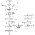
次に、図5〜図7を参照して、本実施形態のデジタル一眼レフカメラでの処理動作について説明する。ステップS101で、MPU100は、スイッチセンス回路105を介してメインスイッチ43がOFFしたか否かを判別する。メインスイッチ43がOFFしたと判別した場合には、ステップS102へ移行する。
Next, processing operations in the digital single-lens reflex camera of this embodiment will be described with reference to FIGS. In step S <b> 101, the
ステップS102で、MPU100は、時刻計測回路109と通信を行い、現在の時刻T1を取得し、EEPROM100aへ記憶後、ステップS103へ移行する。
In step S102, the
ステップS103で、MPU100は、スイッチセンス回路105を介してメインスイッチ43がONしたか否かを判別する。メインスイッチ43がONしたと判別した場合には、ステップS104へ移行する。
In step S103, the
ステップS104で、MPU100は、時刻計測回路109と通信を行い、現在の時刻T2を取得し、ステップS105へ移行する。
In step S104, the
ステップS105で、MPU100は、EEPROM100aに記憶されている時刻T1を呼び出した後、ステップS106へ移行する。ステップS106で、MPU100は、時刻T1と時刻T2を比較して、経過時間T3を算出する。
In step S105, the
ステップS107で、MPU100は、予めEEPROM100aに記憶されている基準時間T0と経過時間T3とを比較する。
In step S107, the
上記ステップS107において基準時間T0が経過時間T3より長い場合、ステップS108へ移行する。ステップS108では、バッテリチェックが開始される。本実施形態では、電源42から所定の負荷(例えば、抵抗等)に通電してバッテリ電圧を降下させ、この降下したバッテリ電圧を検出する、いわゆる直流電圧降下法によるバッテリチェックを行う。すなわち、MPU100は、バッテリチェック回路108に指示を出し、バッテリチェック回路108の動作を開始させる。バッテリチェック回路108は、電源42に対して予め定められた所定の時間の負荷を掛けて、電源42のバッテリ電圧VBATを取得してMPU100に出力する。
When the reference time T0 is longer than the elapsed time T3 in step S107, the process proceeds to step S108. In step S108, a battery check is started. In the present embodiment, a battery check is performed by a so-called DC voltage drop method, in which a predetermined load (for example, a resistor) is energized from the
ステップS109で、MPU100は、上記ステップS108において測定したバッテリ電圧VBATと第2の基準電圧LVL2とを比較する。
In step S109, the
上記ステップS109においてバッテリ電圧VBATが第2の基準電圧LVL2より高いと判別された場合、バッテリ容量が十分あると判断できるので、ステップS110へ移行して、デジタル一眼レフカメラの起動動作を開始させる。その後、ステップS111へ移行して、スタンバイ状態で待機する。 If it is determined in step S109 that the battery voltage VBAT is higher than the second reference voltage LVL2, it can be determined that the battery capacity is sufficient. Therefore, the process proceeds to step S110, and the starting operation of the digital single-lens reflex camera is started. Then, it transfers to step S111 and waits in a standby state.
それに対して、上記ステップS109においてバッテリ電圧VBATが第2の基準電圧LVL2より高くないと判別された場合、バッテリ低下信号を生成し、ステップS112へ移行する。ステップS112で、MPU100は、バッテリ不足の警告表示を外部液晶表示装置9に表示させ、バッテリ交換を撮影者に促し、カメラ動作を停止させる。このときの外部液晶表示装置9での表示例を図4(c)に示す。
On the other hand, if it is determined in step S109 that the battery voltage VBAT is not higher than the second reference voltage LVL2, a battery low signal is generated, and the process proceeds to step S112. In step S112, the
一方、上記ステップS107において基準時間T0が経過時間T3より長くない場合、ステップS113へ移行する。ステップS113で、MPU100は、第2の基準電圧LVL2のレベルをLVL3(<LVL2)へ変更して、ステップS114へ移行する。ステップS114では、バッテリチェックが開始される。すなわち、MPU100は、バッテリチェック回路108に指示を出し、バッテリチェック回路108の動作を開始させ、バッテリ電圧VBATを取得して、ステップS115へ移行する。なお、ステップS114での動作は既述したステップS108と同様であり、その詳細な説明は省略する。
On the other hand, if the reference time T0 is not longer than the elapsed time T3 in step S107, the process proceeds to step S113. In step S113, the
ステップS115で、MPU100は、上記ステップS114において測定したバッテリ電圧VBATと変更した第2の基準電圧LVL3とを比較する。
In step S115, the
上記ステップS115においてバッテリ電圧VBATが変更した第2の基準電圧LVL3より高いと判別された場合、バッテリ容量が十分あると判断できるので、ステップS116へ移行して、デジタル一眼レフカメラの起動動作を開始させる。その後、ステップS111へ移行して、スタンバイ状態で待機する。 If it is determined in step S115 that the battery voltage VBAT is higher than the changed second reference voltage LVL3, it can be determined that the battery capacity is sufficient. Therefore, the process proceeds to step S116 and the start operation of the digital single-lens reflex camera is started. Let Then, it transfers to step S111 and waits in a standby state.
それに対して、上記ステップS115においてバッテリ電圧VBATが変更した第2の基準電圧LVL3より高くないと判別された場合、バッテリ低下信号を生成し、既述したステップS112へ移行する。 On the other hand, if it is determined in step S115 that the battery voltage VBAT is not higher than the changed second reference voltage LVL3, a battery low signal is generated, and the process proceeds to step S112 described above.
図6に説明を移して、ステップS117で、MPU100は、測光・測距開始スイッチSW1(7a)がONであるか否かを検出する。測光・測距開始スイッチSW1(7a)がONであればステップS118に移行し、ONでなければステップS117に戻って、ONになるまでステップS117を繰り返す。
Turning to FIG. 6, in step S117, the
ステップS118で、MPU100は、露光量を決定するために測光回路106を動作させて、測光センサ37にて被写体の光量を測定し、この輝度情報からシャッタースピードとレンズの絞り値を算出し露出量を決定する。さらにMPU100は、被写体の焦点位置を検出して、撮影レンズ200を焦点位置に移動させるために焦点検出回路102を動作させ、位相差検出方式にて焦点検出センサユニット31の不図示のエリアセンサ上に結像した複数の2次光学像のデフォーカス量を算出する。そして、その算出した結果に基づいて撮影レンズ200を焦点位置に移動しピントを合わせる動作を行う。その後、ステップS119に移行する。
In step S118, the
ステップS119で、MPU100は、露光開始スイッチSW2(7b)がONであるか否かを確認する。露光開始スイッチSW2(7b)がONであればステップS120に移行し、ONでなければステップS117へ戻る。
In step S119, the
ステップS120で、MPU100は、バッテリチェック回路108に指示を出し、バッテリチェック回路108の動作を開始させ、バッテリ電圧VBATを取得して、ステップS121へ移行する。
In step S120, the
ステップS121で、MPU100は、上記ステップS120において測定したバッテリ電圧VBATと第1の基準電圧LVL1(>LVL2)とを比較する。
In step S121, the
上記ステップS121においてバッテリ電圧VBATが第1の基準電圧LVL1より高いと判別された場合、バッテリ容量が十分あると判断できるので、ステップS122へ移行する。 If it is determined in step S121 that the battery voltage VBAT is higher than the first reference voltage LVL1, it can be determined that the battery capacity is sufficient, and the process proceeds to step S122.
それに対して、上記ステップS121においてバッテリ電圧VBATが第1の基準電圧LVL1より高くないと判別された場合、バッテリ低下信号を生成し、ステップS123へ移行して、既述したステップS112と同様にバッテリ不足の警告表示を外部液晶表示装置9に表示させ、カメラ動作を停止させる。
On the other hand, if it is determined in step S121 that the battery voltage VBAT is not higher than the first reference voltage LVL1, a battery low signal is generated, the process proceeds to step S123, and the battery is the same as in step S112 described above. An insufficient warning display is displayed on the external liquid
ステップS122では、撮影動作を開始させる。具体的に、まずミラー駆動回路101は、MPU100の命令によりメインミラー64及びサブミラー30をミラーアップ位置に移動する。その後、MPU100は、上記ステップS118において算出された絞り値をレンズ制御回路201へ送信する。レンズ制御回路201は、送信された絞り値まで、絞り駆動回路203によって絞り204を駆動する。
In step S122, the photographing operation is started. Specifically, first, the
次にMPU100は、CCD33の電荷蓄積を開始して、シャッター駆動回路103によって、機械シャッター装置32内の不図示の先羽根群を駆動させ(シャッターが開く)、CCD33の露光を開始する。上記ステップS118において算出されたCCD33の露光時間が終了すると、シャッター駆動回路103は、MPU100の指示に従い、機械シャッター装置32内の後羽根群を駆動して、シャッターを閉じ、CCD33の露光を終了する。
Next, the
絞り駆動回路203は、絞り204を開放の絞り値まで駆動するとともに、ミラー駆動回路101は、メインミラー64及びサブミラー30をミラーダウン位置に移動する。次に電荷蓄積が所定時間行い、MPU100はCCD33の電荷蓄積を終了し、CCD33から電荷信号を読み出して、一連のアナログ処理を行い、A/D変換器36にてA/D変換を行い、映像信号処理回路104に入力する。
The
その後、映像信号処理回路104にて所定の画像処理を施した後に、圧縮処理を行って、メモリコントローラ38にて圧縮されたデータをメモリ39へ記録して、一連の撮影動作が終了して、ステップS124へ移行する。
Thereafter, after performing predetermined image processing in the video
ステップS124で、MPU100は、スイッチセンス回路105を介してメインスイッチ43がOFFしたか否かを判別する。メインスイッチ43がOFFしたと判別した場合には、ステップS102へ移行し、オフしていないと判別した場合には、ステップS117に戻る。
In step S124, the
ここで、図7を参照して、基準電圧LVL1、LVL2、LVL3の関係について説明する。図7は、固体高分子燃料電池の一般的な放電カーブを示し、縦軸は電圧Vを、横軸は時間Tを表わす。 Here, the relationship between the reference voltages LVL1, LVL2, and LVL3 will be described with reference to FIG. FIG. 7 shows a general discharge curve of the polymer electrolyte fuel cell, where the vertical axis represents voltage V and the horizontal axis represents time T.
VL1はカメラの停止後(メインスイッチ43がOFFの状態)、比較的短い時間(図5のステップS107に示すT0>T3と判別される時間)経過した後、電源がONされたときの放電カーブを示している。
VL1 is a discharge curve when the power is turned on after a relatively short time (time determined as T0> T3 shown in step S107 in FIG. 5) after the camera is stopped (
それに対して、VL2はカメラの停止後(メインスイッチ43がOFFの状態)、比較的長い時間(図5のステップS107に示すT0>T3でない(T0≦T3である)と判別される時間)経過した後、電源がONされたときの放電カーブを示している。
On the other hand, VL2 has passed a relatively long time (time determined as not T0> T3 (T0 ≦ T3) shown in step S107 in FIG. 5) after the camera is stopped (
第1の基準電圧LVL1は禁止電圧レベル(カメラが動作可能な電圧を下回る電圧レベル)を示している。既述したバッテリチェックを行い、このLVL1〔V〕以下の電圧と判別されたときには、カメラ動作を停止させる。 The first reference voltage LVL1 indicates a prohibited voltage level (a voltage level lower than a voltage at which the camera can operate). The battery check described above is performed, and when it is determined that the voltage is less than or equal to LVL1 [V], the camera operation is stopped.
ただし、燃料電池の場合、立ち上がり時において、固体高分子膜の加湿状態が低いため一時的に電圧が低くなり、その後、電力を放電することでセルが加湿されるので、すぐに電圧が復帰してカメラが動作可能な状態となる。この一時的に電圧の低い状態で、第1の基準電圧LVL1のレベルでバッテリ状態を判断すると、カメラが動作不能となってしまうおそれがある。 However, in the case of a fuel cell, at the time of startup, the voltage is temporarily reduced because the humidified state of the solid polymer membrane is low, and then the cell is humidified by discharging electric power, so the voltage immediately recovers. The camera is ready for operation. If the battery state is determined at the level of the first reference voltage LVL1 in this temporarily low voltage state, the camera may become inoperable.
そこで、図7に示すように、第1の基準電圧LVL1より低い第2の基準電圧LVL2のレベルにてバッテリチェックを行うことで、この問題を回避することができる。(VL1に示す放電カーブの場合) Therefore, as shown in FIG. 7, by performing the battery check in the first reference voltage L VL1 lower than the second level of the reference voltage LVL2, it is possible to avoid this problem. (In case of discharge curve shown in VL1)
ところで、立ち上がり時の放電カーブは、固体高分子膜の加湿状態によって変化する。つまり、メインスイッチ43がOFFされてから長い時間経過するほど固体高分子膜は乾燥していくことになる。そのため、長い時間経過した場合(VL2に示す放電カーブ)、第2の基準電圧LVL2のレベルでバッテリ状態を判断すると、カメラが動作不能となってしまうおそれがある。
By the way, the discharge curve at the time of rising varies depending on the humidified state of the solid polymer film. In other words, the solid polymer film dries out as a longer time elapses after the
そこで、メインスイッチ43がOFFされてから長い時間(図5のステップS107に示すT0>T3でない(T0≦T3である)と判別される時間)経過した場合は、第2の基準電圧LVL2より低いLVL3のレベルに変更して、その変更した第2の基準電圧LVL3のレベルでバッテリ状態を判別することで、この問題を回避することができる。
Therefore, when a long time has elapsed since the
以上説明したように、メインスイッチ43のON直後では、通常時の禁止電圧レベルである第1の基準電圧LVL1より低い第2の禁止電圧LVL2にてバッテリチェックを行う。したがって、メインスイッチ43のON直後で電圧が低い状態でも、誤検出することなくカメラの起動が可能となる。また、MPU100での処理プログラムを変更するだけで適切なバッテリチェックを行うことができるので、小型化を図るとともに、コストアップを抑えることができる。
As described above, immediately after the
さらに、メインスイッチ43がOFFされてから、次にONされるまでの経過時間が比較的長い場合には、燃料電池内の固体高分子膜がより乾燥した状態にあるとして、第2の基準電圧LVL2を変更する。したがって、加湿状態によって電源スイッチON直後の電圧が変動する場合でも、適切なバッテリチェックが可能となる。
Furthermore, when the elapsed time from when the
(第2の実施形態)
図8〜図9を参照して、第2の実施形態について説明する。なお、第2の実施形態のデジタル一眼レフカメラの構成は、第1の実施形態で説明したものと同様であり、その詳細な説明は省略する。
(Second Embodiment)
The second embodiment will be described with reference to FIGS. Note that the configuration of the digital single-lens reflex camera of the second embodiment is the same as that described in the first embodiment, and a detailed description thereof will be omitted.
ステップS131で、MPU100は、スイッチセンス回路105を介してメインスイッチ43がONしたか否かを判別する。メインスイッチ43がONしたと判別した場合には、ステップS132へ移行する。
In step S131, the
ステップS132で、MPU100は、湿度検出回路110に指令を出して、燃料電池42内の固体高分子膜の加湿状態HMD1を検出してMPU100へ送信し、ステップS133へ移行する。
In step S132, the
ステップS133で、MPU100は、予めEEPROM100aに記憶されている基準湿度HMD0を呼び出して、上記ステップS132において取得した加湿状態HMD1と比較する。
In step S133, the
上記ステップS133においてHMD1>HMD0の場合、すなわち、固体高分子膜の加湿状態が良好な場合、ステップS134へ移行する。ステップS134では、バッテリチェックが開始される。本実施形態では、電源42から所定の負荷(例えば、抵抗等)に通電してバッテリ電圧を降下させ、この降下したバッテリ電圧を検出する、いわゆる直流電圧降下法によるバッテリチェックを行う。すなわち、MPU100は、バッテリチェック回路108に指示を出し、バッテリチェック回路108の動作を開始させる。バッテリチェック回路108は、電源42に対して予め定められた所定の時間の負荷を掛けて、電源42のバッテリ電圧VBATを取得してMPU100に出力する。
If HMD1> HMD0 in step S133, that is, if the humidified state of the solid polymer film is good, the process proceeds to step S134. In step S134, a battery check is started. In the present embodiment, a battery check is performed by a so-called DC voltage drop method, in which a predetermined load (for example, a resistor) is energized from the
ステップS135で、MPU100は、上記ステップS134において測定したバッテリ電圧VBATと第2の基準電圧LVL2とを比較する。
In step S135, the
上記ステップS135においてバッテリ電圧VBATが第2の基準電圧LVL2より高いと判別された場合、バッテリ容量が十分あると判断できるので、ステップS136へ移行して、デジタル一眼レフカメラの起動動作を開始させる。その後、ステップS136へ移行して、スタンバイ状態で待機する。 If it is determined in step S135 that the battery voltage VBAT is higher than the second reference voltage LVL2, it can be determined that the battery capacity is sufficient. Therefore, the process proceeds to step S136, and the starting operation of the digital single lens reflex camera is started. Then, it transfers to step S136 and waits in a standby state.
それに対して、上記ステップS135においてバッテリ電圧VBATが第2の基準電圧LVL2より高くないと判別された場合、バッテリ低下信号を生成し、ステップS138へ移行する。ステップS138で、MPU100は、バッテリ不足の警告表示を外部液晶表示装置9に表示させ、バッテリ交換を撮影者に促し、カメラ動作を停止させる。このときの外部液晶表示装置9での表示例を図4(c)に示す。
On the other hand, if it is determined in step S135 that the battery voltage VBAT is not higher than the second reference voltage LVL2, a battery low signal is generated, and the process proceeds to step S138. In step S138, the
一方、上記ステップS133においてHMD1>HMD0でない(HMD1≦HMD0)の場合、すなわち、固体高分子膜の加湿状態が悪い場合、ステップS139へ移行する。ステップS139で、MPU100は、第2の基準電圧LVL2のレベルをLVL3(<LVL2)へ変更して、ステップS140へ移行する。ステップS140では、バッテリチェックが開始される。すなわち、MPU100は、バッテリチェック回路108に指示を出し、バッテリチェック回路108の動作を開始させ、バッテリ電圧VBATを取得して、ステップS141へ移行する。なお、ステップS140での動作は既述したステップS134と同様であり、その詳細な説明は省略する。
On the other hand, if HMD1> HMD0 is not satisfied (HMD1 ≦ HMD0) in step S133, that is, if the humidified state of the solid polymer film is bad, the process proceeds to step S139. In step S139, the
ステップS141で、MPU100は、上記ステップS140において測定したバッテリ電圧VBATと変更した第2の基準電圧LVL3とを比較する。
In step S141, the
上記ステップS141においてバッテリ電圧VBATが変更した第2の基準電圧LVL3より高いと判別された場合、バッテリ容量が十分あると判断できるので、ステップS142へ移行して、デジタル一眼レフカメラの起動動作を開始させる。その後、ステップS137へ移行して、スタンバイ状態で待機する。 If it is determined in step S141 that the battery voltage VBAT is higher than the changed second reference voltage LVL3, it can be determined that the battery capacity is sufficient. Therefore, the process proceeds to step S142 and the start operation of the digital single-lens reflex camera is started. Let Then, it transfers to step S137 and waits in a standby state.
それに対して、上記ステップS141においてバッテリ電圧VBATが変更した第2の基準電圧LVL3より高くないと判別された場合、バッテリ低下信号を生成し、既述したステップS138へ移行する。 On the other hand, if it is determined in step S141 that the battery voltage VBAT is not higher than the changed second reference voltage LVL3, a battery low signal is generated, and the process proceeds to step S138 described above.
ステップS137のスタンバイ状態後、図9のステップS143へ移行する。ステップS143〜ステップS150の処理動作は、第1の実施形態で説明した図6のステップS117〜ステップS124の処理動作と同様であり、その詳細な説明は省略する。 After the standby state in step S137, the process proceeds to step S143 in FIG. The processing operations in steps S143 to S150 are the same as the processing operations in steps S117 to S124 in FIG. 6 described in the first embodiment, and detailed description thereof is omitted.
以上説明したように、メインスイッチ43のON直後では、通常時の禁止電圧レベルである第1の基準電圧LVL1より低い第2の禁止電圧LVL2にてバッテリチェックを行う。したがって、メインスイッチ43のON直後で電圧が低い状態でも、誤検出することなくカメラの起動が可能となる。また、MPU100での処理プログラムを変更するだけで適切なバッテリチェックを行うことができるので、小型化を図るとともに、コストアップを抑えることができる。
As described above, immediately after the
さらに、固体高分子膜の加湿状態に応じて、第2の基準電圧LVL2を変更するようにしたので、加湿状態によって電源スイッチON直後の電圧が変動する場合でも、適切なバッテリチェックが可能となる。 Furthermore, since the second reference voltage LVL2 is changed in accordance with the humidification state of the solid polymer film, even when the voltage immediately after the power switch is turned on varies depending on the humidification state, an appropriate battery check can be performed. .
(第3の実施形態)
図10〜図12を参照して、第3の実施の形態について説明する。なお、第3の実施形態のデジタル一眼レフカメラの構成は、第1の実施形態で説明したものと同様であり、その詳細な説明は省略する。
(Third embodiment)
A third embodiment will be described with reference to FIGS. The configuration of the digital single-lens reflex camera of the third embodiment is the same as that described in the first embodiment, and a detailed description thereof is omitted.
第3の実施形態では、バッテリチェック回路108が第1の負荷、第2の負荷、第3の負荷という3種類の負荷によるバッテリチェックを行うように構成されている。この場合に、第1の負荷>第2の負荷>第3の負荷という関係になっている。例えば特許文献5に開示されているように、異なる抵抗値を示す抵抗を3種類持ち、それらを切り替えて使うことで達成することができる(第1の負荷の抵抗値>第2の負荷の抵抗値>第3の負荷の抵抗値)。
In the third embodiment, the
図10のステップS201〜ステップS206の処理動作は、第1の実施形態で説明した図5のステップS101〜ステップS106の処理動作と同様であり、その詳細な説明は省略する。 The processing operations in steps S201 to S206 in FIG. 10 are the same as the processing operations in steps S101 to S106 in FIG. 5 described in the first embodiment, and detailed description thereof is omitted.
ステップS207で、MPU100は、予めEEPROM100aに記憶されている基準時間T0と経過時間T3とを比較する。
In step S207, the
上記ステップS207において所定時間T0が経過時間T3より長い場合、ステップS208へ移行する。ステップS208では、バッテリチェックが開始される。なお、第3の実施形態のバッテリチェックは、第1の実施形態のバッテリチェックと同一の方式のため、ここでの説明は省略する。MPU100は、バッテリチェック回路108に指示を出し、第2の負荷によるバッテリチェック(BC)を行い、電源42のバッテリ電圧VBATを取得してMPU100に出力する。
If the predetermined time T0 is longer than the elapsed time T3 in step S207, the process proceeds to step S208. In step S208, a battery check is started. Note that the battery check of the third embodiment is the same method as the battery check of the first embodiment, and a description thereof will be omitted here. The
一方、上記ステップS207において所定時間T0が経過時間T3より長くない場合、ステップS213へ移行する。ステップS213で、MPU100は、第2の負荷を第3の負荷へ変更して、ステップS214へ移行する。ステップS214では、MPU100は、バッテリチェック回路108に指示を出し、第3の負荷によるにバッテリチェック(BC)を行い、電源42のバッテリ電圧VBATを取得してMPU100に出力する。
On the other hand, if the predetermined time T0 is not longer than the elapsed time T3 in step S207, the process proceeds to step S213. In step S213, the
その後のステップS209〜ステップS212やステップS215、216は、第1の実施形態で説明した図5のステップS109〜ステップS112やステップS115、116の処理動作と同様であり、その詳細な説明は省略する。ただし、本実施形態では、バッテリチェックに際して基準電圧はLVL0一定となっている。 Subsequent steps S209 to S212 and steps S215 and 216 are the same as the processing operations of steps S109 to S112 and steps S115 and 116 of FIG. 5 described in the first embodiment, and detailed description thereof is omitted. . However, in the present embodiment, the reference voltage is constant at LVL0 during the battery check.
ステップS211のスタンバイ状態後、図11のステップS217へ移行する。ステップS217〜ステップS219、ステップS221〜ステップS224の処理動作は、第1の実施形態で説明した図6のステップS117〜ステップS119、ステップS121〜ステップS124の処理動作と同様であり、その詳細な説明は省略する。ただし、本実施形態では、バッテリチェックに際して基準電圧はLVL0一定となっている。 After the standby state in step S211, the process proceeds to step S217 in FIG. The processing operations of steps S217 to S219 and steps S221 to S224 are the same as the processing operations of steps S117 to S119 and steps S121 to S124 of FIG. Is omitted. However, in the present embodiment, the reference voltage is constant at LVL0 during the battery check.
ステップS220で、MPU100は、バッテリチェック回路108に指示を出し、バッテリチェック回路108の動作を開始させ、第1の負荷によるにバッテリチェック(BC)を行い、電源42のバッテリ電圧VBATを取得してMPU100に出力する。
In step S220, the
ここで、図12を参照して、第1の負荷、第2の負荷、第3の負荷の関係について説明する。図12は、固体高分子燃料電池の一般的な放電カーブを示し、縦軸は電圧Vを、横軸は時間Tを示している。 Here, the relationship between the first load, the second load, and the third load will be described with reference to FIG. FIG. 12 shows a general discharge curve of the polymer electrolyte fuel cell, in which the vertical axis indicates voltage V and the horizontal axis indicates time T.
図12(a)のVL1はカメラの停止後(メインスイッチ43がOFFの状態)、比較的短い時間(図10のステップS207に示すT0>T3と判別される時間)経過した後、電源がONされたときの放電カーブを示している。
VL1 in FIG. 12A is turned on after a relatively short time (time determined as T0> T3 shown in step S207 of FIG. 10) has elapsed after the camera is stopped (
それに対して、図12(b)のVL2はカメラの停止後(メインスイッチ43がOFFの状態)、比較的長い時間(図10のステップS207に示すT0>T3でない(T0≦T3である)と判別される時間)経過した後、電源がONされたときの放電カーブを示している。
On the other hand, VL2 in FIG. 12B is a relatively long time after the camera is stopped (
各負荷の矢印の長さは、バッテリチェックを行って電圧が降下する量を示す。バッテリチェックを行ったときに測定された電圧が、禁止レベルLVL0を下回ったときにカメラの動作を停止させる。 The length of the arrow of each load indicates the amount of voltage drop caused by the battery check. The camera operation is stopped when the voltage measured when the battery check is performed falls below the inhibition level LVL0.
図12(a)に示すように、通常時の負荷である第1の負荷でバッテリチェックを行う場合、水素の供給が無くなり電圧が下がる領域であれば、ここで禁止レベルと判断してカメラを停止させることは問題がない。 As shown in FIG. 12 (a), when the battery check is performed with the first load, which is a normal load, if the hydrogen supply is lost and the voltage drops, the camera is determined to be at the prohibited level here. There is no problem to stop.
しかしながら、立ち上がり時において第1の負荷でバッテリチェックを行うと、これから電圧が上がってカメラが動作可能であるにもかかわらず停止させてしまうという問題が発生する。 However, if a battery check is performed with the first load at the time of start-up, there is a problem that the voltage will increase and the camera will stop even though it can operate.
そこで、立ち上がり時は第1の負荷よりも小さい第2の負荷にてバッテリチェックを行うことで、図12(a)に示すように、禁止レベル以下にならないようにしている。 Therefore, the battery check is performed with a second load smaller than the first load at the time of start-up, so that the level is not lower than the prohibition level as shown in FIG.
また、燃料電池の場合、固体高分子膜の加湿状態が悪い(潤っていない)と、立ち上がり時の電圧はさらに低くなってしまう。特にメインスイッチがOFFされてから、長い時間が経過すると乾燥してしまう。 In the case of a fuel cell, if the solid polymer membrane is in a poorly humid state (not moistened), the voltage at the time of start-up becomes even lower. In particular, after a long time has elapsed since the main switch was turned off, the air would dry.
そこで、このときには第2の負荷よりもさらに低い第3の負荷を用いてバッテリチェックを行うことで、上記問題を回避することができる。つまり、図12(b)に示すように、仮に第2の負荷によりバッテリチェックを行うと禁止レベルとなってしまうが、第3の負荷によりバッテリチェックを行うことで、禁止レベルを下回ることが無くなる。 Therefore, at this time, the above problem can be avoided by performing a battery check using a third load that is lower than the second load. In other words, as shown in FIG. 12B, if the battery check is performed with the second load, the prohibition level is reached. However, the battery check with the third load does not drop below the prohibition level. .
以上説明したように、メインスイッチ43のON直後では、通常時のバッテリチェック負荷である第1の負荷より軽い第2の負荷によるバッテリチェックを行う。したがって、メインスイッチ43のON直後で電圧が低い状態でも、誤検出することなくカメラの起動が可能となる。また、MPU100での処理プログラムを変更するだけで適切なバッテリチェックを行うことができるので、小型化を図るとともに、コストアップを抑えることができる。
As described above, immediately after the
さらに、メインスイッチ43がOFFされてから、次にONされるまでの経過時間が比較的長い場合には、燃料電池内の固体高分子膜がより乾燥した状態にあるとして、第2の負荷を第3の負荷へと変更する。したがって、加湿状態によって電源スイッチON直後の電圧が変動する場合でも、適切なバッテリチェックが可能となる。
Furthermore, if the elapsed time from when the
(第4の実施形態)
図13〜図14を参照して、第4の実施形態について説明する。なお、第4の実施形態のデジタル一眼レフカメラの構成は、第3の実施形態で説明したものと同様であり、その詳細な説明は省略する。
(Fourth embodiment)
A fourth embodiment will be described with reference to FIGS. Note that the configuration of the digital single lens reflex camera of the fourth embodiment is the same as that described in the third embodiment, and a detailed description thereof will be omitted.
図13のステップS231〜ステップS232の処理動作は、第2の実施形態で説明したの図8のステップS131〜ステップS132と同様であり、その詳細な説明は省略する。 The processing operations in steps S231 to S232 in FIG. 13 are the same as those in steps S131 to S132 in FIG. 8 described in the second embodiment, and detailed description thereof is omitted.
ステップS233で、MPU100は、予めEEPROM100aに記憶されている基準湿度HMD0を呼び出して、上記ステップS232において取得した加湿状態HMD1と比較する。
In step S233, the
上記ステップS233においてHMD1>HMD0の場合、すなわち、固体高分子膜の加湿状態が良好な場合、ステップS234へ移行する。ステップS234で、MPU100は、第2の負荷によるバッテリチェックを行い、電源42のバッテリ電圧VBATを取得してMPU100に出力する。
If HMD1> HMD0 in step S233, that is, if the humidified state of the solid polymer film is good, the process proceeds to step S234. In step S234, the
一方、ステップS233においてHMD1>HMD0でない(HMD1≦HMD0である)の場合、すなわち、固体高分子膜の加湿状態が悪い場合、ステップS239へ移行する。ステップS239で、MPU100は、第2の負荷を第3の負荷へ変更して、ステップS240へ移行する。ステップS240で、MPU100は、第3の負荷によるバッテリチェックを行い、電源42のバッテリ電圧VBATを取得してMPU100に出力する。
On the other hand, if HMD1> HMD0 is not satisfied (HMD1 ≦ HMD0) in step S233, that is, if the humidified state of the solid polymer film is bad, the process proceeds to step S239. In step S239, the
その後のステップS236〜ステップS238やステップS241、242は、第2の実施形態で説明した図8のステップS136〜ステップS138やステップS141、142の処理動作と同様であり、その詳細な説明は省略する。ただし、本実施形態では、バッテリチェックに際して基準電圧はLVL0一定となっている。 Subsequent steps S236 to S238 and steps S241 and 242 are the same as the processing operations of steps S136 to S138 and steps S141 and 142 of FIG. 8 described in the second embodiment, and detailed description thereof is omitted. . However, in the present embodiment, the reference voltage is constant at LVL0 during the battery check.
ステップS237のスタンバイ状態後、図14のステップS243へ移行する。ステップS243〜ステップS250の処理動作は、第3の実施形態で説明した図11のステップS217〜ステップS224の処理動作と同様であり、その詳細な説明は省略する。 After the standby state in step S237, the process proceeds to step S243 in FIG. The processing operations in steps S243 to S250 are the same as the processing operations in steps S217 to S224 of FIG. 11 described in the third embodiment, and detailed description thereof is omitted.
以上説明したように、メインスイッチ43のON直後では、通常時のバッテリチェック負荷である第1の負荷より軽い第2の負荷によるバッテリチェックを行う。したがって、メインスイッチ43のON直後で電圧が低い状態でも、誤検出することなくカメラの起動が可能となる。また、MPU100での処理プログラムを変更するだけで適切なバッテリチェックを行うことができるので、小型化を図るとともに、コストアップを抑えることができる。
As described above, immediately after the
さらに、固体高分子膜の加湿状態に応じて、第2の負荷を変更するようにしたので、加湿状態によって電源スイッチON直後の電圧が変動する場合でも、適切なバッテリチェックが可能となる。 Furthermore, since the second load is changed in accordance with the humidified state of the solid polymer film, an appropriate battery check can be performed even when the voltage immediately after the power switch is turned on varies depending on the humidified state.
(第5の実施形態)
図15を参照して、第5の実施形態について説明する。なお、第5の実施形態のデジタル一眼レフカメラの構成は、第1の実施形態デ説明したものと同様であり、その詳細な説明は省略する。
(Fifth embodiment)
The fifth embodiment will be described with reference to FIG. Note that the configuration of the digital single-lens reflex camera of the fifth embodiment is the same as that described in the first embodiment, and a detailed description thereof will be omitted.
ステップS301で、MPU100は、スイッチセンス回路105を介してメインスイッチ43がONしたか否かを判別する。メインスイッチ43がONしたと判別した場合には、ステップS302へ移行する。
In step S301, the
ステップS302では、バッテリチェックが開始される。本実施形態では、電源42から所定の負荷(例えば、抵抗等)に通電してバッテリ電圧を降下させ、この降下したバッテリ電圧を検出する、いわゆる直流電圧降下法によるバッテリチェックを行う。すなわち、MPU100は、バッテリチェック回路108に指示を出し、バッテリチェック回路108の動作を開始させる。バッテリチェック回路108は、電源42に対して予め定められた所定の時間の負荷を掛けて、電源42のバッテリ電圧V1(第1の電圧)を取得してMPU100に出力する。MPU100は、第1の電圧V1をEEPROM100aに記憶後、ステップS303へ移行する。
In step S302, a battery check is started. In the present embodiment, a battery check is performed by a so-called DC voltage drop method, in which a predetermined load (for example, a resistor) is energized from the
ステップS303で、MPU100は、予めEEPROM100aに格納されているタイマーをスタートさせ、ステップS304で、タイムアップしたか否かを検出する。ステップS304においてタイムアップしたと判別したときには、ステップS305へ移行し、タイムアップしていないと判別したときにはステップS304の処理動作を繰り返す。
In step S303, the
ステップS305で、MPU100は、再びバッテリチェック回路108に指示を出し、バッテリチェック回路108の動作を開始させる。バッテリチェック回路108は、電源42に対して予め定められた所定の時間の負荷を掛けて、電源42のバッテリ電圧(第2の電圧)を取得してMPU100に出力し、ステップS306へ移行する。
In step S305, the
ステップS306で、MPU100は、EEPROM100aに記憶された第1の電圧V1と、上記ステップS305において取得した第2の電圧V2とを比較する。
In step S306, the
上記ステップS306において第2の電圧V2>第1の電圧V1の場合、燃料電池42が立ち上がり状態にある(電圧の変化の傾きが上昇)と判断する。そして、ステップS307へ移行して、デジタル一眼レフカメラの起動動作を開始させ、ステップS308へ移行して、スタンバイ状態で待機する。
When the second voltage V2> the first voltage V1 in step S306, it is determined that the
それに対して、上記ステップS306において第2の電圧V2>第1の電圧でない場合、燃料電池42が立ち下がり状態にある(電圧の変化の傾きが下降)と判断する。そして、禁止電圧レベルと判断してバッテリ低下信号を生成し、ステップS309へ移行する。
On the other hand, if the second voltage V2> the first voltage is not satisfied in step S306, it is determined that the
ステップS309で、MPU100は、バッテリ不足の警告表示を外部液晶表示装置9に表示させ、バッテリ交換を撮影者に促し、さらにステップS310で、カメラ動作を停止させる。このときの外部液晶表示装置9での表示例を図4(c)に示す。
In step S309, the
以上説明したように、第1の電圧V1と、所定時間だけおいた後の第2の電圧V2とから、電圧が立ち上がり状態にあるのか、立ち下がり状態にあるのかを判別する。したがって、メインスイッチ43のON直後で電圧が低い状態でも、立ち上がり状態と判別したときには、誤検出することなくカメラの起動が可能となる。また、MPU100での処理プログラムを変更するだけで適切なバッテリチェックを行うことができるので、小型化を図るとともに、コストアップを抑えることができる。
As described above, whether the voltage is in the rising state or the falling state is determined from the first voltage V1 and the second voltage V2 after a predetermined time. Therefore, even if the voltage is low immediately after the
なお、本発明の目的は、上述した実施形態の機能を実現するソフトウェアのプログラムコードを記録した記憶媒体を、システム或いは装置に供給し、そのシステム或いは装置のコンピュータ(又はCPUやMPU)が記憶媒体に格納されたプログラムコードを読み出し実行することによっても、達成されることは言うまでもない。 An object of the present invention is to supply a storage medium storing software program codes for realizing the functions of the above-described embodiments to a system or apparatus, and the computer (or CPU or MPU) of the system or apparatus stores the storage medium. Needless to say, this can also be achieved by reading and executing the program code stored in.
この場合、記憶媒体から読み出されたプログラムコード自体が上述した実施形態の機能を実現することになり、プログラムコード自体及びそのプログラムコードを記憶した記憶媒体は本発明を構成することになる。 In this case, the program code itself read from the storage medium realizes the functions of the above-described embodiments, and the program code itself and the storage medium storing the program code constitute the present invention.
プログラムコードを供給するための記憶媒体としては、例えば、フレキシブルディスク、ハードディスク、光ディスク、光磁気ディスク、CD−ROM、CD−R、磁気テープ、不揮発性のメモリカード、ROM等を用いることができる。 As a storage medium for supplying the program code, for example, a flexible disk, a hard disk, an optical disk, a magneto-optical disk, a CD-ROM, a CD-R, a magnetic tape, a nonvolatile memory card, a ROM, or the like can be used.
また、コンピュータが読み出したプログラムコードを実行することにより、上述した実施形態の機能が実現されるだけでなく、そのプログラムコードの指示に基づき、コンピュータ上で稼動しているOS(基本システム或いはオペレーティングシステム)等が実際の処理の一部又は全部を行い、その処理によって上述した実施形態の機能が実現される場合も含まれることは言うまでもない。 Further, by executing the program code read by the computer, not only the functions of the above-described embodiments are realized, but also an OS (basic system or operating system) running on the computer based on the instruction of the program code. Needless to say, a case where the functions of the above-described embodiment are realized by performing part or all of the actual processing and the processing is included.
さらに、記憶媒体から読み出されたプログラムコードが、コンピュータに挿入された機能拡張ボードやコンピュータに接続された機能拡張ユニットに備わるメモリに書き込まれた後、そのプログラムコードの指示に基づき、その機能拡張ボードや機能拡張ユニットに備わるCPU等が実際の処理の一部又は全部を行い、その処理によって上述した実施形態の機能が実現される場合も含まれることは言うまでもない。 Further, after the program code read from the storage medium is written to a memory provided in a function expansion board inserted into the computer or a function expansion unit connected to the computer, the function expansion is performed based on the instruction of the program code. It goes without saying that the CPU or the like provided in the board or function expansion unit performs part or all of the actual processing, and the functions of the above-described embodiments are realized by the processing.
9‥外部液晶表示装置
14‥撮影モード設定ダイヤル
42‥電源(燃料電池)
43‥メインスイッチ
100‥マイクロコンピュータ
105‥スイッチセンス回路
107‥液晶表示駆動回路
108‥バッテリチェック回路
109‥時刻計測回路
110‥湿度検出回路
9 ... External liquid
43 ...
Claims (5)
前記燃料電池による前記電子機器への電力供給の開始および停止を制御する電源スイッチと、
前記燃料電池の電圧を基準電圧と比較するバッテリチェック手段と、
前記基準電圧を切り換えて前記バッテリチェック手段を動作させる制御手段とを有し、
前記制御手段は、
前記電源スイッチによって前記電子機器への電力供給が開始されて起動動作を開始した後に、前記バッテリチェック手段を動作させる場合には、前記基準電圧を第1の基準電圧に切り換えて前記バッテリチェック手段を動作させ、
前記電源スイッチによって前記電子機器への電力供給が開始されて起動動作を開始する前に、前記バッテリチェック手段を動作させる場合であって、かつ前記電源スイッチによって前記電子機器への電力供給が停止されてから、前記電源スイッチによって前記電子機器への電力供給が開始されるまでの経過時間が予め設定される時間よりも短い場合には、前記基準電圧を前記第1の基準電圧より小さい第2の基準電圧に切り換えて前記バッテリチェック手段を動作させ、
前記電源スイッチによって前記電子機器への電力供給が開始されて起動動作を開始する前に、前記バッテリチェック手段を動作させる場合であって、かつ前記電源スイッチによって前記電子機器への電力供給が停止されてから、前記電源スイッチによって前記電子機器への電力供給が開始されるまでの経過時間が予め設定される時間よりも長い場合には、前記基準電圧を前記第2の基準電圧より小さい第3の基準電圧に切り換えて前記バッテリチェック手段を動作させることを特徴とする電子機器。 A fuel cell for supplying power to the electronic device;
A power switch for controlling start and stop of power supply to the electronic device by the fuel cell;
Battery check means for comparing the fuel cell voltage with a reference voltage;
Control means for operating the battery check means by switching the reference voltage,
The control means includes
When operating the battery check unit after the power supply to the electronic device is started by the power switch and starting the startup operation, the battery check unit is switched to the first reference voltage by switching the reference voltage. Make it work,
The battery check means is operated before power supply to the electronic device is started by the power switch and the starting operation is started, and power supply to the electronic device is stopped by the power switch. If the elapsed time from the start of power supply to the electronic device by the power switch is shorter than a preset time, the reference voltage is set to a second value smaller than the first reference voltage. Switch to a reference voltage to operate the battery check means,
The battery check means is operated before power supply to the electronic device is started by the power switch and the starting operation is started, and power supply to the electronic device is stopped by the power switch. If the elapsed time from the start of power supply to the electronic device by the power switch is longer than a preset time, the reference voltage is set to a third value smaller than the second reference voltage. electronic apparatus characterized Rukoto to operate the battery checking means is switched to the reference voltage.
前記燃料電池による前記電子機器への電力供給の開始および停止を制御する電源スイッチと、
前記燃料電池の電力を負荷に接続するバッテリチェック手段と、
前記負荷を切り換えて前記バッテリチェック手段を動作させる制御手段とを有し、
前記制御手段は、
前記電源スイッチによって前記電子機器への電力供給が開始されて起動動作を開始した後に、前記バッテリチェック手段を動作させる場合には、前記負荷を第1の負荷に切り換えて前記バッテリチェック手段を動作させ、
前記電源スイッチによって前記電子機器への電力供給が開始されて起動動作を開始する前に、前記バッテリチェック手段を動作させる場合であって、かつ前記電源スイッチによって前記電子機器への電力供給が停止されてから、前記電源スイッチによって前記電子機器への電力供給が開始されるまでの経過時間が予め設定される時間よりも短い場合には、前記負荷を前記第1の負荷より小さい第2の負荷に切り換えて前記バッテリチェック手段を動作させ、
前記電源スイッチによって前記電子機器への電力供給が開始されて起動動作を開始する前に、前記バッテリチェック手段を動作させる場合であって、かつ前記電源スイッチによって前記電子機器への電力供給が停止されてから、前記電源スイッチによって前記電子機器への電力供給が開始されるまでの経過時間が予め設定される時間よりも長い場合には、前記負荷を前記第2の負荷より小さい第3の負荷に切り換えて前記バッテリチェック手段を動作させることを特徴とする電子機器。 A fuel cell for supplying power to the electronic device;
A power switch for controlling start and stop of power supply to the electronic device by the fuel cell;
Battery check means for connecting the power of the fuel cell to a load;
Control means for operating the battery check means by switching the load,
The control means includes
When the battery check means is operated after the power supply to the electronic device is started by the power switch and the starting operation is started, the battery check means is operated by switching the load to the first load. ,
The battery check means is operated before power supply to the electronic device is started by the power switch and the starting operation is started, and power supply to the electronic device is stopped by the power switch. When the elapsed time from when the power supply switch starts to supply power to the electronic device is shorter than a preset time, the load is changed to a second load smaller than the first load. Switch to operate the battery check means,
The battery check means is operated before power supply to the electronic device is started by the power switch and the starting operation is started, and power supply to the electronic device is stopped by the power switch. If the elapsed time from when the power supply switch starts to supply power to the electronic device is longer than a preset time, the load is changed to a third load smaller than the second load. switched electronic apparatus characterized Rukoto to operate the battery checking means.
前記燃料電池による前記電子機器への電力供給の開始および停止を制御する電源スイッチと、
前記燃料電池の電圧を基準電圧と比較するバッテリチェック手段と、
前記燃料電池の固体高分子膜の湿度を検出する湿度検出手段と、
前記基準電圧を切り換えて前記バッテリチェック手段を動作させる制御手段とを有し、
前記制御手段は、
前記電源スイッチによって前記電子機器への電力供給が開始されて起動動作を開始した後に、前記バッテリチェック手段を動作させる場合には、前記基準電圧を第1の基準電圧に切り換えて前記バッテリチェック手段を動作させ、
前記電源スイッチによって前記電子機器への電力供給が開始されて起動動作を開始する前に、前記バッテリチェック手段を動作させる場合であって、かつ前記湿度検出手段によって検出される前記固体高分子膜の湿度が予め設定される湿度よりも高い場合には、前記基準電圧を前記第1の基準電圧より小さい第2の基準電圧に切り換えて前記バッテリチェック手段を動作させ、
前記電源スイッチによって前記電子機器への電力供給が開始されて起動動作を開始する前に、前記バッテリチェック手段を動作させる場合であって、かつ前記湿度検出手段によって検出される前記固体高分子膜の湿度が予め設定される湿度よりも低い場合には、前記基準電圧を前記第2の基準電圧より小さい第3の基準電圧に切り換えて前記バッテリチェック手段を動作させることを特徴とする電子機器。 A fuel cell for supplying power to the electronic device;
A power switch for controlling start and stop of power supply to the electronic device by the fuel cell;
Battery check means for comparing the fuel cell voltage with a reference voltage;
Humidity detecting means for detecting the humidity of the solid polymer membrane of the fuel cell;
Control means for operating the battery check means by switching the reference voltage,
The control means includes
When operating the battery check unit after the power supply to the electronic device is started by the power switch and starting the startup operation, the battery check unit is switched to the first reference voltage by switching the reference voltage. Make it work,
The battery check means is operated before power supply to the electronic device is started by the power switch and the start-up operation is started, and the solid polymer film detected by the humidity detection means When the humidity is higher than a preset humidity, the reference voltage is switched to a second reference voltage smaller than the first reference voltage to operate the battery check means,
The battery check means is operated before power supply to the electronic device is started by the power switch and the start-up operation is started, and the solid polymer film detected by the humidity detection means is lower than the humidity humidity is set in advance, electronic apparatus characterized isosamples switches the reference voltage to the second reference voltage less than the third reference voltage to operate the battery checking means.
前記燃料電池による前記電子機器への電力供給の開始および停止を制御する電源スイッチと、
前記燃料電池の電力を負荷に接続するバッテリチェック手段と、
前記燃料電池の固体高分子膜の湿度を検出する湿度検出手段と、
前記負荷を切り換えて前記バッテリチェック手段を動作させる制御手段とを有し、
前記制御手段は、
前記電源スイッチによって前記電子機器への電力供給が開始されて起動動作を開始した後に、前記バッテリチェック手段を動作させる場合には、前記負荷を第1の負荷に切り換えて前記バッテリチェック手段を動作させ、
前記電源スイッチによって前記電子機器への電力供給が開始されて起動動作を開始する前に、前記バッテリチェック手段を動作させる場合であって、かつ前記湿度検出手段によって検出される前記固体高分子膜の湿度が予め設定される湿度よりも高い場合には、前記負荷を前記第1の負荷より小さい第2の負荷に切り換えて前記バッテリチェック手段を動作させ、
前記電源スイッチによって前記電子機器への電力供給が開始されて起動動作を開始する前に、前記バッテリチェック手段を動作させる場合であって、かつ前記湿度検出手段によって検出される前記固体高分子膜の湿度が予め設定される湿度よりも低い場合には、前記負荷を前記第2の負荷より小さい第3の負荷に切り換えて前記バッテリチェック手段を動作させることを特徴とする電子機器。 A fuel cell for supplying power to the electronic device;
A power switch for controlling start and stop of power supply to the electronic device by the fuel cell;
Battery check means for connecting the power of the fuel cell to a load;
Humidity detecting means for detecting the humidity of the solid polymer membrane of the fuel cell;
Control means for operating the battery check means by switching the load,
The control means includes
When the battery check means is operated after the power supply to the electronic device is started by the power switch and the starting operation is started, the battery check means is operated by switching the load to the first load. ,
The battery check means is operated before power supply to the electronic device is started by the power switch and the start-up operation is started, and the solid polymer film detected by the humidity detection means When the humidity is higher than a preset humidity, the load is switched to a second load smaller than the first load to operate the battery check means,
The battery check means is operated before power supply to the electronic device is started by the power switch and the start-up operation is started, and the solid polymer film detected by the humidity detection means is lower than the humidity humidity is set in advance, electronic apparatus characterized Rukoto to operate the battery checking means is switched to the load to the second load is less than the third load.
Priority Applications (5)
| Application Number | Priority Date | Filing Date | Title |
|---|---|---|---|
| JP2005317182A JP5032762B2 (en) | 2005-10-31 | 2005-10-31 | Electronics |
| US11/580,101 US7939214B2 (en) | 2005-10-31 | 2006-10-13 | Electronic equipment provided with voltage check unit |
| CNB2006101498927A CN100521740C (en) | 2005-10-31 | 2006-10-31 | Electronic equipment provided with battery check device |
| US12/972,335 US8968952B2 (en) | 2005-10-31 | 2010-12-17 | Electronic equipment provided with battery check device |
| US14/568,006 US9172105B2 (en) | 2005-10-31 | 2014-12-11 | Electronic equipment provided with battery check device |
Applications Claiming Priority (1)
| Application Number | Priority Date | Filing Date | Title |
|---|---|---|---|
| JP2005317182A JP5032762B2 (en) | 2005-10-31 | 2005-10-31 | Electronics |
Publications (3)
| Publication Number | Publication Date |
|---|---|
| JP2007123187A JP2007123187A (en) | 2007-05-17 |
| JP2007123187A5 JP2007123187A5 (en) | 2008-12-11 |
| JP5032762B2 true JP5032762B2 (en) | 2012-09-26 |
Family
ID=37996767
Family Applications (1)
| Application Number | Title | Priority Date | Filing Date |
|---|---|---|---|
| JP2005317182A Expired - Fee Related JP5032762B2 (en) | 2005-10-31 | 2005-10-31 | Electronics |
Country Status (3)
| Country | Link |
|---|---|
| US (3) | US7939214B2 (en) |
| JP (1) | JP5032762B2 (en) |
| CN (1) | CN100521740C (en) |
Families Citing this family (7)
| Publication number | Priority date | Publication date | Assignee | Title |
|---|---|---|---|---|
| KR101377317B1 (en) * | 2007-01-25 | 2014-03-26 | 엘지전자 주식회사 | Power control apparatus, Ending-mode checking method, Driving method and Power control method of Terminal |
| JP4803532B2 (en) * | 2007-04-06 | 2011-10-26 | Necカシオモバイルコミュニケーションズ株式会社 | Electronic device and electronic device program |
| JP4954937B2 (en) | 2007-05-08 | 2012-06-20 | パナソニック株式会社 | Disk device and disk drive device |
| JP5195031B2 (en) * | 2008-05-28 | 2013-05-08 | 富士通モバイルコミュニケーションズ株式会社 | Mobile device |
| TWI421507B (en) * | 2008-07-11 | 2014-01-01 | Hon Hai Prec Ind Co Ltd | System and method for indicating remaining power of an electronic device |
| JP5085626B2 (en) * | 2009-10-08 | 2012-11-28 | レノボ・シンガポール・プライベート・リミテッド | Battery pack, firmware update method thereof, and battery pack system |
| JP6275187B2 (en) * | 2016-04-28 | 2018-02-07 | 本田技研工業株式会社 | Vehicle control system, vehicle control method, and vehicle control program |
Family Cites Families (25)
| Publication number | Priority date | Publication date | Assignee | Title |
|---|---|---|---|---|
| JPH0622159B2 (en) * | 1984-11-29 | 1994-03-23 | 株式会社日立製作所 | Detection method of abnormal single cell in laminated battery |
| JPH0547394A (en) * | 1991-08-08 | 1993-02-26 | Fuji Electric Co Ltd | Solid polymer electrolyte fuel cell and operating method thereof |
| JPH0792523A (en) | 1993-09-24 | 1995-04-07 | Nikon Corp | Camera with battery check circuit device |
| JPH08195211A (en) * | 1995-01-18 | 1996-07-30 | Toyota Motor Corp | Fuel cell system |
| JP4028603B2 (en) | 1996-02-05 | 2007-12-26 | 松下電器産業株式会社 | Fuel cell device for equipment |
| DE69708715T2 (en) * | 1996-02-05 | 2002-08-08 | Matsushita Electric Ind Co Ltd | Fuel cell for mounting on devices |
| JP3927657B2 (en) * | 1997-07-25 | 2007-06-13 | キヤノン株式会社 | Cameras and electronic devices |
| JP3929158B2 (en) | 1998-02-13 | 2007-06-13 | カルソニックカンセイ株式会社 | Fluid level measuring device |
| JP3674466B2 (en) | 1999-11-24 | 2005-07-20 | セイコーエプソン株式会社 | Voltage detection device, battery remaining amount detection device, voltage detection method, battery remaining amount detection method, electronic timepiece, and electronic device |
| JP3636068B2 (en) * | 2000-02-16 | 2005-04-06 | 日産自動車株式会社 | Fuel cell control device |
| US6841275B2 (en) * | 2001-12-14 | 2005-01-11 | Ballard Power Systems Inc. | Method and apparatus for controlling voltage from a fuel cell system |
| JP2003234116A (en) | 2002-02-07 | 2003-08-22 | Canon Inc | Control method and control device of fuel cell |
| JP2003295284A (en) | 2002-04-08 | 2003-10-15 | Olympus Optical Co Ltd | Camera |
| KR100562614B1 (en) * | 2002-04-15 | 2006-03-17 | 마츠시타 덴끼 산교 가부시키가이샤 | Fuel cell system |
| JP3832417B2 (en) * | 2002-10-22 | 2006-10-11 | 日産自動車株式会社 | Fuel cell system |
| JP4001004B2 (en) * | 2002-12-10 | 2007-10-31 | 日立アプライアンス株式会社 | Operation control device for fuel cell system |
| JP4407124B2 (en) * | 2003-01-08 | 2010-02-03 | 株式会社ニコン | Electronics |
| JP2004220844A (en) * | 2003-01-10 | 2004-08-05 | Sanyo Electric Co Ltd | Fuel cell system |
| JP4742486B2 (en) | 2003-04-10 | 2011-08-10 | 日産自動車株式会社 | Fuel cell power generation control device |
| US7632583B2 (en) * | 2003-05-06 | 2009-12-15 | Ballard Power Systems Inc. | Apparatus for improving the performance of a fuel cell electric power system |
| US7518262B2 (en) * | 2003-07-23 | 2009-04-14 | The Japan Research Insitute, Limited | Power supply system, multiple dwelling, and computer program |
| JP2005085537A (en) * | 2003-09-05 | 2005-03-31 | Nissan Motor Co Ltd | Fuel cell system |
| KR100527469B1 (en) * | 2003-10-10 | 2005-11-09 | 현대자동차주식회사 | A temperature and a humidity control device of fuel cell stack and method thereof |
| JP4664607B2 (en) * | 2004-02-27 | 2011-04-06 | 株式会社東芝 | FUEL CELL UNIT, INFORMATION PROCESSING DEVICE, FUEL CELL UNIT CONTROL METHOD, AND INFORMATION PROCESSING DEVICE POWER SUPPLY METHOD |
| US7592083B2 (en) * | 2005-10-07 | 2009-09-22 | Gm Global Technology Operations, Inc. | Integrated air supply with humidification control for fuel cell power systems |
-
2005
- 2005-10-31 JP JP2005317182A patent/JP5032762B2/en not_active Expired - Fee Related
-
2006
- 2006-10-13 US US11/580,101 patent/US7939214B2/en not_active Expired - Fee Related
- 2006-10-31 CN CNB2006101498927A patent/CN100521740C/en not_active Expired - Fee Related
-
2010
- 2010-12-17 US US12/972,335 patent/US8968952B2/en not_active Expired - Fee Related
-
2014
- 2014-12-11 US US14/568,006 patent/US9172105B2/en not_active Expired - Fee Related
Also Published As
| Publication number | Publication date |
|---|---|
| US20150099203A1 (en) | 2015-04-09 |
| JP2007123187A (en) | 2007-05-17 |
| CN100521740C (en) | 2009-07-29 |
| US9172105B2 (en) | 2015-10-27 |
| US20070099046A1 (en) | 2007-05-03 |
| CN1972381A (en) | 2007-05-30 |
| US20110091783A1 (en) | 2011-04-21 |
| US8968952B2 (en) | 2015-03-03 |
| US7939214B2 (en) | 2011-05-10 |
Similar Documents
| Publication | Publication Date | Title |
|---|---|---|
| US9172105B2 (en) | Electronic equipment provided with battery check device | |
| US9705143B2 (en) | Electronic apparatus, control method and program thereof, and battery for operating electronic apparatus | |
| JP2007248521A (en) | Image recording apparatus, image recording method, program and recording medium | |
| JP4994595B2 (en) | Electronics | |
| JP2008079136A (en) | Imaging device and its control method, program, and storage medium | |
| JP5105770B2 (en) | Electronic device, control method thereof, and program | |
| JP2003344919A (en) | Photographing device | |
| JP2007123186A (en) | Electronic equipment and its control method | |
| JP4700865B2 (en) | Recording device | |
| JP2008005353A (en) | Imaging apparatus, control method thereof and computer program | |
| JP2006222529A (en) | Imaging apparatus | |
| JP2008270987A (en) | Image pickup device and its control method | |
| JP2007060720A (en) | Camera accessory device | |
| JP4253089B2 (en) | Imaging device | |
| JP2010245786A (en) | Imaging apparatus | |
| JP4420702B2 (en) | Camera with built-in flash | |
| JP2005321490A (en) | Camera | |
| JP2006129045A (en) | Camera system and battery pack for camera | |
| JP2004087171A (en) | Portable apparatus | |
| JP2005259655A (en) | Fuel cell and electronic apparatus | |
| JP4769507B2 (en) | Imaging device | |
| JP2009043505A (en) | Battery holder of camera | |
| JP2009011089A (en) | Electronic equipment, and judgment method of battery run-down | |
| JP2005223571A (en) | Digital camera | |
| JP2004087170A (en) | Portable apparatus |
Legal Events
| Date | Code | Title | Description |
|---|---|---|---|
| A521 | Request for written amendment filed |
Free format text: JAPANESE INTERMEDIATE CODE: A523 Effective date: 20081023 |
|
| A621 | Written request for application examination |
Free format text: JAPANESE INTERMEDIATE CODE: A621 Effective date: 20081023 |
|
| A131 | Notification of reasons for refusal |
Free format text: JAPANESE INTERMEDIATE CODE: A131 Effective date: 20111018 |
|
| A521 | Request for written amendment filed |
Free format text: JAPANESE INTERMEDIATE CODE: A523 Effective date: 20111213 |
|
| TRDD | Decision of grant or rejection written | ||
| A01 | Written decision to grant a patent or to grant a registration (utility model) |
Free format text: JAPANESE INTERMEDIATE CODE: A01 Effective date: 20120626 |
|
| A01 | Written decision to grant a patent or to grant a registration (utility model) |
Free format text: JAPANESE INTERMEDIATE CODE: A01 |
|
| A61 | First payment of annual fees (during grant procedure) |
Free format text: JAPANESE INTERMEDIATE CODE: A61 Effective date: 20120629 |
|
| FPAY | Renewal fee payment (event date is renewal date of database) |
Free format text: PAYMENT UNTIL: 20150706 Year of fee payment: 3 |
|
| LAPS | Cancellation because of no payment of annual fees |