JP5032063B2 - Non-aqueous electrolyte battery, battery pack and automobile - Google Patents
Non-aqueous electrolyte battery, battery pack and automobile Download PDFInfo
- Publication number
- JP5032063B2 JP5032063B2 JP2006157517A JP2006157517A JP5032063B2 JP 5032063 B2 JP5032063 B2 JP 5032063B2 JP 2006157517 A JP2006157517 A JP 2006157517A JP 2006157517 A JP2006157517 A JP 2006157517A JP 5032063 B2 JP5032063 B2 JP 5032063B2
- Authority
- JP
- Japan
- Prior art keywords
- negative electrode
- positive electrode
- battery
- sectional area
- current collector
- Prior art date
- Legal status (The legal status is an assumption and is not a legal conclusion. Google has not performed a legal analysis and makes no representation as to the accuracy of the status listed.)
- Active
Links
Images


Classifications
-
- Y—GENERAL TAGGING OF NEW TECHNOLOGICAL DEVELOPMENTS; GENERAL TAGGING OF CROSS-SECTIONAL TECHNOLOGIES SPANNING OVER SEVERAL SECTIONS OF THE IPC; TECHNICAL SUBJECTS COVERED BY FORMER USPC CROSS-REFERENCE ART COLLECTIONS [XRACs] AND DIGESTS
- Y02—TECHNOLOGIES OR APPLICATIONS FOR MITIGATION OR ADAPTATION AGAINST CLIMATE CHANGE
- Y02E—REDUCTION OF GREENHOUSE GAS [GHG] EMISSIONS, RELATED TO ENERGY GENERATION, TRANSMISSION OR DISTRIBUTION
- Y02E60/00—Enabling technologies; Technologies with a potential or indirect contribution to GHG emissions mitigation
- Y02E60/10—Energy storage using batteries
-
- Y—GENERAL TAGGING OF NEW TECHNOLOGICAL DEVELOPMENTS; GENERAL TAGGING OF CROSS-SECTIONAL TECHNOLOGIES SPANNING OVER SEVERAL SECTIONS OF THE IPC; TECHNICAL SUBJECTS COVERED BY FORMER USPC CROSS-REFERENCE ART COLLECTIONS [XRACs] AND DIGESTS
- Y02—TECHNOLOGIES OR APPLICATIONS FOR MITIGATION OR ADAPTATION AGAINST CLIMATE CHANGE
- Y02P—CLIMATE CHANGE MITIGATION TECHNOLOGIES IN THE PRODUCTION OR PROCESSING OF GOODS
- Y02P70/00—Climate change mitigation technologies in the production process for final industrial or consumer products
- Y02P70/50—Manufacturing or production processes characterised by the final manufactured product
Landscapes
- Cell Electrode Carriers And Collectors (AREA)
- Secondary Cells (AREA)
- Connection Of Batteries Or Terminals (AREA)
- Battery Electrode And Active Subsutance (AREA)
Description
本発明は、リチウムイオン非水電解質電池、電池パックおよびこれらが搭載された自動
車に係わる。
The present invention relates to a lithium ion non-aqueous electrolyte battery, a battery pack, and an automobile on which these are mounted.
リチウムイオンが負極と正極とを移動することにより充放電が行われる非水電解質電池
は、高エネルギー密度電池として盛んに研究開発が進められている。
Non-aqueous electrolyte batteries that are charged and discharged by moving lithium ions between a negative electrode and a positive electrode are actively researched and developed as high energy density batteries.
正極活物質としてリチウム遷移金属複合酸化物を用い、負極活物質として炭素質物を用
いる非水電解質電池が既に商用化されている。リチウム遷移金属複合酸化物は、遷移金属
としてCo、Mn、Ni等を用いるのが一般的である。
Nonaqueous electrolyte batteries using a lithium transition metal composite oxide as a positive electrode active material and a carbonaceous material as a negative electrode active material have already been commercialized. The lithium transition metal composite oxide generally uses Co, Mn, Ni or the like as a transition metal.
近年、炭素質物に比してLi吸蔵放出電位が高い(約1.55V vs Li/Li+)リチウムチタン
複合酸化物を負極活物質として用いた非水電解質電池が提案された。リチウムチタン複合
酸化物は、充放電に伴う体積変化が小さいため、充放電の可逆性に優れるという特徴を有
する。また、リチウムチタン複合酸化物を負極活物質に用いた電池では、原理的にリチウ
ム金属が析出することがないため、大電流での充電が可能になる。すなわち、急速充電が
可能となる。
In recent years, a nonaqueous electrolyte battery using a lithium-titanium composite oxide having a higher Li storage / release potential (about 1.55 V vs. Li / Li + ) than a carbonaceous material as a negative electrode active material has been proposed. The lithium titanium composite oxide has a feature that the reversibility of charge / discharge is excellent because the volume change accompanying charge / discharge is small. In addition, in a battery using a lithium-titanium composite oxide as a negative electrode active material, lithium metal is not deposited in principle, and thus charging with a large current is possible. That is, rapid charging is possible.
従来の炭素質物を負極活物質にした非水電解質電池では、負極集電体に銅箔を、負極リ
ードにニッケルを用いることが一般的であった。しかし、上述したLi吸蔵・放出電位が高
い負極活物質を用いた電池では、負極の作用電位がアルミニウムの合金化電位(リチウム
と反応する電位)よりも貴であるため、負極集電体や負極リードに正極側と同じアルミニ
ウムを用いることが可能となる。このことは、電池の軽量化や低コスト化に繋がるため、
炭素質物を用いた従来の電池に対して大きなメリットとなる。このようなアルミニウムを
負極集電体に用いた電池は特許文献1で開示されている。
This is a significant advantage over conventional batteries using carbonaceous materials. A battery using such aluminum as a negative electrode current collector is disclosed in Patent Document 1.
発明者らが鋭意研究した結果、両極の集電体およびリードにアルミニウムを用いた電池
は、外部で短絡した場合の電池内部発熱が大きいことが分かってきた。この原因は以下の
通りである。
As a result of intensive studies by the inventors, it has been found that a battery using aluminum for both current collectors and leads has a large heat generation inside the battery when short-circuited externally. The cause is as follows.
炭素質物を負極活物質に用いた従来の非水電解質電池の場合には、負極リードであるニ
ッケル材の電気抵抗が、他の集電体やリード材のそれに比べて極端に大きい(20℃での電
気抵抗率は、アルミニウムが2.69×10⁻⁸Ωm、銅が1.673×10⁻⁸Ωmに対して、ニッケル
は6.844×10⁻⁸Ωm)ために、外部短絡で大電流(例えば数百〜千数百A以上)が流れた
場合に、負極リードであるニッケル材が抵抗発熱によって急激に発熱し、真っ先に溶断す
る。この結果、電池にこれ以上の電流が流れ続けることはなく、電池内部での発熱は抑止
され、電池は安全に電池機能を失ってくれる。
In the case of a conventional nonaqueous electrolyte battery using a carbonaceous material as the negative electrode active material, the electric resistance of the nickel material, which is the negative electrode lead, is extremely large compared to that of other current collectors and lead materials (at 20 ° C). the electrical resistivity of aluminum is 2.69 × 10 -8 Ωm, relative to copper 1.673 × 10 -8 Ωm, nickel in 6.844 × 10 -8 Ωm) for large current (for example, several hundred to 1000 with external short circuit When several hundred A or more) flows, the nickel material as the negative electrode lead suddenly generates heat due to resistance heat generation and blows out first. As a result, no more current continues to flow through the battery, heat generation inside the battery is suppressed, and the battery loses its battery function safely.
一方で、両極のリードにアルミニウムを用いた場合には、電気抵抗が低いので、外部短
絡が生じても発熱量が小さく、リードが溶断する処まで至らない。さらに、両極の集電体
がアルミニウムであると、電気抵抗が低いゆえに、より大電流が流れ抵抗加熱が生じる。
集電体に生じた熱は、電極層へと直接的に伝わり、電池が熱暴走する恐れがあった。
On the other hand, when aluminum is used for the leads of both electrodes, the electrical resistance is low, so even if an external short circuit occurs, the amount of heat generation is small and the lead cannot be melted. Furthermore, if the current collectors of both electrodes are aluminum, the electric resistance is low, so that a larger current flows and resistance heating occurs.
The heat generated in the current collector was directly transmitted to the electrode layer, and there was a risk that the battery would run out of heat.
これを回避するためには、外付けの安全措置が必要になる。しかしながら、このような
安全装置を取り付けると、エネルギー密度が低下してしまい、好ましくなかった。
To avoid this, external safety measures are required. However, when such a safety device is attached, the energy density is lowered, which is not preferable.
本発明は、上記事情に鑑みて為されたものであり、外部短絡時の安全性に優れた非水電
解質電池、電池パックおよび自動車を提供することを目的とする。
The present invention has been made in view of the above circumstances, and an object thereof is to provide a nonaqueous electrolyte battery, a battery pack, and an automobile that are excellent in safety at the time of an external short circuit.
本発明の非水電解質電池は、外装材と、外装材内に充填された非水電解質と、外装材内に収納された正極層と、正極層に坦持され、アルミニウムもしくはアルミニウム合金で形成された正極集電体と、正極集電体の一部が延出した正極タブと、一端が正極タブに接続され、他端が外装材の外に延出した、アルミニウムもしくはアルミニウム合金で形成された正極リードと、外装材内に収納され、リチウム吸蔵・放出電位が0.4V(vs Li/Li+)より貴である負極活物質を含む負極層と、負極層に坦持され、アルミニウムもしくはアルミニウム合金で形成された負極集電体と、負極集電体の一部が延出した負極タブと、一端が負極タブに接続され、他端が外装材の外に延出した、アルミニウムもしくはアルミニウム合金で形成された負極リードと、を具備し、電流が流れる方向に垂直な正極タブの総断面積は、電流が流れる方向に垂直な正極リードの最小断面積より大きく、電流が流れる方向に垂直な負極タブの総断面積は、電流が流れる方向に垂直な負極リードの最小断面積より大きく、前記正極リードの最小断面積は、前記負極リードの最小断面積より大きいことを特徴とする。
The non-aqueous electrolyte battery of the present invention is formed of an exterior material, a non-aqueous electrolyte filled in the exterior material, a positive electrode layer accommodated in the exterior material, and carried on the positive electrode layer and made of aluminum or an aluminum alloy. A positive electrode current collector, a positive electrode tab in which a part of the positive electrode current collector extends, one end connected to the positive electrode tab, and the other end formed of aluminum or an aluminum alloy extending outside the exterior material. A positive electrode lead, a negative electrode layer containing a negative electrode active material that is housed in an exterior material, and has a lithium occlusion / release potential more noble than 0.4 V (vs Li / Li +), and carried on the negative electrode layer and made of aluminum or an aluminum alloy Formed with aluminum or aluminum alloy, formed negative electrode current collector, negative electrode tab with a part of the negative electrode current collector extended, one end connected to the negative electrode tab and the other end extended out of the exterior material Negative electrode lead, The total cross-sectional area of the positive electrode tab perpendicular to the current flowing direction is larger than the minimum cross-sectional area of the positive electrode lead perpendicular to the current flowing direction, and the total cross-sectional area of the negative electrode tab perpendicular to the current flowing direction is rather greater than the minimum cross-sectional area perpendicular negative electrode lead in the direction of flow, the minimum cross-sectional area of the positive electrode lead is characterized in that the larger minimum cross-sectional area of the negative electrode lead.
本発明の電池パックは、上述の非水電解質電池の組電池を具備することを特徴とする。 The battery pack of the present invention is characterized by comprising the above-mentioned assembled battery of nonaqueous electrolyte batteries.
本発明の自動車は、上述の電池パックを搭載したことを特徴とする。 The automobile of the present invention is equipped with the above-described battery pack.
本発明は、外部短絡時の安全性に優れた非水電解質電池、電池パックおよび自動車を提
供できる。
The present invention can provide a nonaqueous electrolyte battery, a battery pack, and an automobile excellent in safety at the time of an external short circuit.
以下に、本発明の各実施の形態について図面を参照しながら説明する。なお、実施の形
態を通して共通の構成には同一の符号を付すものとし、重複する説明は省略する。また、
各図は発明の説明とその理解を促すための模式図であり、その形状や寸法、比などは実際
の装置と異なる個所があるが、これらは以下の説明と公知の技術を参酌して適宜、設計変
更することができる。
Hereinafter, embodiments of the present invention will be described with reference to the drawings. In addition, the same code | symbol shall be attached | subjected to a common structure through embodiment, and the overlapping description is abbreviate | omitted. Also,
Each figure is a schematic diagram for facilitating explanation and understanding of the invention, and its shape, dimensions, ratio, etc. are different from the actual device, but these are appropriately determined in consideration of the following explanation and known technology. The design can be changed.
(第1の実施形態)
第1の実施形態に係る非水電解質電池について図1を参照して説明する。図1は第1の
実施形態に係る非水電解質電池の別な例を模式的に示す部分切欠斜視図で、図2は図1の
A部の拡大断面図である。
(First embodiment)
The nonaqueous electrolyte battery according to the first embodiment will be described with reference to FIG. FIG. 1 is a partially cutaway perspective view schematically showing another example of the nonaqueous electrolyte battery according to the first embodiment, and FIG. 2 is an enlarged cross-sectional view of a portion A in FIG.
図1に示すように、ラミネートフィルム製の外装材1内には、積層型電極群2が収納さ
れている。積層型電極群2は、図2に示すように、正極3と負極4とをその間にセパレー
タ5を介在させながら交互に積層した構造を有する。正極3は複数枚存在し、それぞれが
正極集電体3aと、正極集電体3aの両面に担持された正極活物質含有層3bとを備える
。負極4は複数枚存在し、それぞれが負極集電体4aと、負極集電体4aの両面に担持さ
れた負極活物質含有層4bとを備える。それぞれの負極4の負極集電体4aは、一辺が正
極3から突出している。この突出した部分(以後、負極タブとする。)は負極集電体4a
の一部が延出して形成されている。負極タブは、帯状の負極リード6の一端に電気的に接
続されている。帯状の負極リード6の他端は、外装材8から外部に引き出されている。
As shown in FIG. 1, a laminated
A part of is extended and formed. The negative electrode tab is electrically connected to one end of the strip-shaped
また、ここでは図示しないが、正極3の正極集電体3aは、負極タブと反対側に位置す
る辺が負極4から突出している。この突出した部分(以後、正極タブとする。)は正極集
電体3aの一部が延出して形成されている。正極タブは、帯状の正極リード1の一端に電
気的に接続されている。帯状の正極リード7の他端は、外装材8の辺から外部に引き出さ
れている。正極リード7が外装材8から引き出されている方向は、負極リード6が外装材
8から引き出されている方向と反対向きである。なお、図2中、セパレータ5は点線で表
したが、これは便宜的なものであり、実際上のセパレータ5の断面を示すものではない。
Although not shown here, the positive
ここで、負極集電体4aの上面模式図を図3に示す。負極集電体4aは、負極層が形成
される領域4a2と、負極層が形成されない領域である負極タブ4a1と、に分けられる
。負極タブ4a1は、負極層が形成される領域4a2の一辺の一部が延出されて形成され
る。
Here, a schematic top view of a negative electrode
第1の実施形態では、正極集電体3a、負極集電体4a、正極リード7および負極リー
ド6の夫々は、アルミニウムもしくはアルミニウム合金で形成される。これは、負極活物
質のリチウム吸蔵・放出電位が0.4V(vs Li/Li+)より貴であることに起因する。
In the first embodiment, each of the positive electrode
従来は、このような構成を持つ非水電解質電池において、外部短絡が生じた場合、上述
した理由により、電池内部の発熱が大きくなってしまっていた。発明者らは鋭意研究した
結果、このような電池の発熱挙動(熱分布)は、正極負極夫々における、電流が流れる方
向に垂直なリードの最小断面積と、電流が流れる方向に垂直なタブの総断面積と、の比率
で大きく変化することを見出した。
Conventionally, in a non-aqueous electrolyte battery having such a configuration, when an external short circuit occurs, heat generation inside the battery has increased for the reasons described above. As a result of intensive research, the inventors have found that the heat generation behavior (heat distribution) of the battery is such that the minimum cross-sectional area of the lead perpendicular to the direction of current flow and the tab perpendicular to the direction of current flow are positive and negative. It was found that the ratio changes greatly with the ratio of the total cross-sectional area.
すなわち、電流が流れる方向に垂直なタブの総断面積が、電流が流れる方向に垂直な正
極リードの最小断面積より小さい場合には、タブに近い電池内部は大きく発熱する。しか
しながら、逆の場合、すなわち、電流が流れる方向に垂直なタブの総断面積は、電流が流
れる方向に垂直なリードの最小断面積より大きい場合には、電池内部の発熱がリードの発
熱よりも小さくなることが分かった。
That is, when the total cross-sectional area of the tab perpendicular to the direction in which the current flows is smaller than the minimum cross-sectional area of the positive electrode lead perpendicular to the direction in which the current flows, the inside of the battery near the tab generates a large amount of heat. However, in the opposite case, that is, when the total cross-sectional area of the tab perpendicular to the direction in which the current flows is larger than the minimum cross-sectional area of the lead perpendicular to the direction in which the current flows, the heat generation in the battery is greater than the heat generation in the lead. It turned out to be smaller.
前者の場合には、電池内部の急激な発熱が電池の異状発熱(電解液や正極活物質の熱分
解など)を誘発し、電池の安全性を低下させる。一方、後者の場合は、電池内部の発熱よ
りもリードの発熱が顕著となり、リードが溶断して電池機能を安全に消失させることが可
能となった。
In the former case, sudden heat generation inside the battery induces abnormal heat generation of the battery (such as thermal decomposition of the electrolytic solution and the positive electrode active material), thereby reducing the safety of the battery. On the other hand, in the latter case, the heat generation of the lead becomes more significant than the heat generation inside the battery, and the lead can be melted and the battery function can be safely lost.
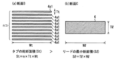
ここで、負極の場合を例とし、タブの総断面積とリードの最小断面積の比較について、
図4を参照して説明する。図4(a)は、図2の線Bで表される断面におけるタブの断面
を示した模式図である。なお、便宜上、タブの枚数は10枚とした。図4(b)は、図2
の線Cで表される断面におけるリードの断面積を示した模式図である。図4(a)に示す
ように、負極タブ4a1の厚さTtと幅Wtとを掛けることにより負極タブ4a1の断面
積を算出する。その後、負極タブ4a1の枚数と負極タブ4a1の断面積とを掛けること
により、負極タブの総断面積を算出する。一方、図4(b)に示すように、負極リード2
の断面積は、負極リード2の厚さTlと幅Wlとを掛けることにより算出する。なお、断
面積が最小であるか否かは、適宜何箇所か測定を行うことによって求める。また、寸法は
ノギスで測定した。
Here, taking the case of the negative electrode as an example, for comparison of the total cross-sectional area of the tab and the minimum cross-sectional area of the lead,
This will be described with reference to FIG. FIG. 4A is a schematic view showing a cross section of the tab in the cross section represented by line B in FIG. For convenience, the number of tabs is set to 10. FIG. 4B is the same as FIG.
It is the schematic diagram which showed the cross-sectional area of the lead in the cross section represented by line C. As shown in FIG. 4A, the cross-sectional area of the negative electrode tab 4a1 is calculated by multiplying the thickness Tt and the width Wt of the negative electrode tab 4a1. Thereafter, the total cross-sectional area of the negative electrode tab is calculated by multiplying the number of the negative electrode tabs 4a1 by the cross-sectional area of the negative electrode tab 4a1. On the other hand, as shown in FIG.
Is calculated by multiplying the thickness Tl of the
電流が流れる方向に垂直な負極リードの最小断面積は、電流が流れる方向に垂直な負極
タブの総断面積より小さい。負極リードの最小断面積(SNL)と負極タブの総断面積(SNT
)の比率(SNT/SNL)が1.3以上10以下であることが好ましい。この比率が1.3より小さい
とタブの溶断が起こり難く、電池内部の温度上昇が顕著になる。10より大きいと、負極リ
ードの抵抗が大きくなりすぎて、電池性能(負荷特性)が低下してしまう。より好ましい
範囲は、1.5以上6以下である。
The minimum cross-sectional area of the negative electrode lead perpendicular to the direction in which the current flows is smaller than the total cross-sectional area of the negative electrode tab perpendicular to the direction in which the current flows. Minimum cross-sectional area of negative electrode lead (S NL ) and total cross-sectional area of negative electrode tab (S NT
) Ratio (S NT / S NL ) is preferably 1.3 or more and 10 or less. If this ratio is less than 1.3, the tabs are hardly melted and the temperature inside the battery rises significantly. When it is larger than 10, the resistance of the negative electrode lead becomes too large, and the battery performance (load characteristic) is deteriorated. A more preferable range is 1.5 or more and 6 or less.
同様に、電流が流れる方向に垂直な正極リードの最小断面積は、電流が流れる方向に垂
直な正極タブの総断面積より小さい。正極リードの最小断面積(SPL)と正極タブの総断
面積(SPT)の比率(SPT/SPL)が1.3以上10以下であることが好ましい。この比率が1.3よ
り小さいとタブの溶断が起こり難く、電池内部の温度上昇が顕著になる。10より大きいと
、正極リードの抵抗が大きくなりすぎて、電池性能(負荷特性)が低下してしまう。より
好ましい範囲は、1.5以上6以下である。
Similarly, the minimum cross-sectional area of the positive electrode lead perpendicular to the direction of current flow is smaller than the total cross-sectional area of the positive electrode tab perpendicular to the direction of current flow. The ratio (S PT / S PL ) of the minimum cross-sectional area (S PL ) of the positive electrode lead to the total cross-sectional area (S PT ) of the positive electrode tab is preferably 1.3 or more and 10 or less. If this ratio is less than 1.3, the tabs are hardly melted and the temperature inside the battery rises significantly. When it is larger than 10, the resistance of the positive electrode lead becomes too large, and the battery performance (load characteristic) is deteriorated. A more preferable range is 1.5 or more and 6 or less.
このようなリードの溶断が生じる場合は、外部短絡時に電池に大電流が流れる場合に限
られる。すなわち、電池の内部抵抗が高く、外部短絡を行っても大電流が流れない場合に
は、このような効果は小さくなる。したがって、本発明の効果が有効に機能する電池の構
成としては、電池の内部抵抗が10mΩ以下であることが好ましい。このような電池は電極
層の厚さを60μm以下、電池容量を2Ah以上とすることで容易に達成できる。なお、ここ
で、集電体の両面に電極層を形成した場合、電極層の厚さとは、片面のみの厚さをいうも
のとする。
Such lead fusing occurs only when a large current flows through the battery during an external short circuit. That is, when the internal resistance of the battery is high and a large current does not flow even if an external short circuit is performed, such an effect is reduced. Therefore, as a battery configuration in which the effect of the present invention functions effectively, it is preferable that the internal resistance of the battery is 10 mΩ or less. Such a battery can be easily achieved by setting the electrode layer thickness to 60 μm or less and the battery capacity to 2 Ah or more. Here, when electrode layers are formed on both sides of the current collector, the thickness of the electrode layer means the thickness of only one side.
また、正極リードの最小断面積は負極リードの最小断面積に比べて、大きいことが好ま
しい。これは以下の理由による。
The minimum cross-sectional area of the positive electrode lead is preferably larger than the minimum cross-sectional area of the negative electrode lead. This is due to the following reason.
正極は負極に比べて発熱を伴う電解液の分解が激しく、正極活物質自身も熱分解するた
め、電池の異状発熱が誘発され易い。すなわち、正極は負極に比して発熱耐性が低い。し
たがって、電池の発熱は正極側よりも負極側で優先的に生じる方が好ましい。負極側に抵
抗発熱を優先的に生じさせるためには、上述の構成を採ることが有効である。何故ならば
、正極リード、負極リード、正極タブ、負極タブの中で、電流の流れる断面積を比較した
場合において、負極リードが最も小さい断面積となり、同時に最も抵抗発熱が生じやすい
箇所となるからである。
Compared with the negative electrode, the positive electrode has a more severe decomposition of the electrolytic solution, and the positive electrode active material itself is also thermally decomposed. Therefore, abnormal heat generation of the battery is easily induced. That is, the positive electrode has lower heat generation resistance than the negative electrode. Therefore, it is preferable that the heat generation of the battery occurs preferentially on the negative electrode side than on the positive electrode side. In order to preferentially generate resistance heat generation on the negative electrode side, it is effective to adopt the above-described configuration. This is because, among the positive electrode lead, the negative electrode lead, the positive electrode tab, and the negative electrode tab, when comparing the cross-sectional areas through which current flows, the negative electrode lead has the smallest cross-sectional area, and at the same time, it is the place where resistance heating is most likely to occur. It is.
このような効果は、特に正極に層状構造を有する遷移金属酸化物を用いた場合に顕著に
現れる。スピネル構造やオリビン構造を有する正極活物質に比べて、構造安定性が低く、
熱分解温度が低いためである。
Such an effect is particularly prominent when a transition metal oxide having a layered structure is used for the positive electrode. Compared to the positive electrode active material having a spinel structure or olivine structure, the structural stability is low,
This is because the thermal decomposition temperature is low.
正極リードの最小断面積(SPL)と負極リードの最小断面積(SNL)の比率(SPL/SNL)
は、1.01以上3以下であることが好ましい。(SPL/SNL)が1.01より小さいと負極側を優先
的に発熱させる効果に乏しく、3を超えると、リードの強度バランスが不均等で、振動試
験など行った際に、負極リードに負担が掛かり、破壊してしまうためである。より好まし
い範囲は1.03以上2以下である。
Ratio of the minimum cross-sectional area (S PL ) of the positive electrode lead to the minimum cross-sectional area (S NL ) of the negative electrode lead (S PL / S NL )
Is preferably 1.01 or more and 3 or less. If (S PL / S NL ) is less than 1.01, the negative electrode side will not have the effect of preferentially generating heat, and if it exceeds 3, the strength balance of the leads will be uneven and burdens on the negative electrode lead during vibration tests etc. It is because it takes and destroys. A more preferable range is 1.03 or more and 2 or less.
さらに、類似の議論から、正極タブの総断面積は、負極タブの総断面積より大きいこと
が好ましい。ただし、この場合、負極リードが最も小さい断面積となる訳ではない。よっ
て、正極負極のリードの最小断面積を調整した方が効果は顕著である。
Further, from a similar argument, it is preferable that the total cross-sectional area of the positive electrode tab is larger than the total cross-sectional area of the negative electrode tab. However, in this case, the negative electrode lead does not have the smallest cross-sectional area. Therefore, the effect is more remarkable when the minimum cross-sectional area of the positive and negative electrode leads is adjusted.
正極リードの最小断面積(SPT)と負極リードの最小断面積(SNT)の比率(SPT/SNT)
は、1.01以上3以下であることが好ましい。(SPT/SNT)が1.01より小さいと負極側を優先
的に発熱させる効果に乏しく、3を超えると、タブの強度バランスが不均等で、振動試験
など行った際に、負極タブに負担が掛かり、破壊してしまうためである。より好ましい範
囲は1.03以上2以下である。
Ratio of the minimum cross-sectional area (S PT ) of the positive electrode lead to the minimum cross-sectional area (S NT ) of the negative electrode lead (S PT / S NT )
Is preferably 1.01 or more and 3 or less. If (S PT / S NT ) is smaller than 1.01, the negative electrode side is not preferentially heated, and if it exceeds 3, the strength balance of the tab is uneven and burdens the negative electrode tab when performing vibration tests. It is because it takes and destroys. A more preferable range is 1.03 or more and 2 or less.
正極リード、負極リード、正極タブおよび負極タブは、長方形であり、電流方向に対し
て垂直方向の幅が略同一であることが好ましい。幅が小さい領域が存在すると、外部から
の振動などによる曲げなどの剪断応力が働いたときに、幅が小さい領域が核となって、リ
ード或いはタブが切れ易くなってしまう。アルミニウムもしくはアルミニウム合金箔は引
張には強いが、曲げ剪断が弱いためである。
The positive electrode lead, the negative electrode lead, the positive electrode tab, and the negative electrode tab are preferably rectangular and have substantially the same width in the direction perpendicular to the current direction. If a region with a small width exists, when a shearing stress such as bending due to external vibration or the like is applied, the region with the small width becomes a nucleus, and the lead or tab is likely to be cut. This is because aluminum or aluminum alloy foil is strong in tension but weak in bending shear.
なお、略同一とは、製造誤差の範囲内のことを指す。一般に、タブ・リード加工などの
幅方向の精度は±0.1mm位であり、実施例にて後述するタブ・リード幅から考えると±0.5
%となる。また、タブ・リードの厚みの精度は±0.1μm程度。実施例にて後述する集電体
(タブ)厚さ15μm厚さから考えると±0.67%程度となる。
Note that “substantially the same” means within a range of manufacturing errors. Generally, the accuracy in the width direction of tab / lead processing is about ± 0.1mm, and considering the tab / lead width described later in the examples, it is ± 0.5.
%. The tab / lead thickness accuracy is about ± 0.1μm. Considering the current collector (tab) thickness of 15 μm, which will be described later in the examples, it is about ± 0.67%.
以下、負極、正極、非水電解質、セパレータ、外装材、負極リード、正極リードについ
て、材料を中心として詳細に説明する。
Hereinafter, the negative electrode, the positive electrode, the nonaqueous electrolyte, the separator, the exterior material, the negative electrode lead, and the positive electrode lead will be described in detail mainly on the materials.
1)負極
この負極は、負極集電体と、前記集電体の片面もしくは両面に担持され、活物質、導電
剤および結着剤を含む負極活物質含有層とを有する。
1) Negative electrode This negative electrode includes a negative electrode current collector and a negative electrode active material-containing layer that is supported on one or both surfaces of the current collector and includes an active material, a conductive agent, and a binder.
0.4V(vs.Li/Li+)より貴な電位でリチウムを吸蔵することが可能な負極活物質は、金
属酸化物、金属硫化物、金属窒化物あるいは合金であることが望ましい。
The negative electrode active material capable of occluding lithium at a potential nobler than 0.4 V (vs. Li / Li + ) is preferably a metal oxide, metal sulfide, metal nitride, or alloy.
このような金属酸化物としては、例えば、チタン含有金属複合酸化物、例えばSnB0.
4P0.6O3.1などのアモルファススズ酸化物、例えばSnSiO3などのスズ珪素酸化物、
例えばSiOなどの酸化珪素、例えばWO3などのタングステン酸化物などが挙げられる
。中でも、チタン含有金属複合酸化物が好ましい。
Examples of such metal oxides include titanium-containing metal composite oxides such as SnB 0.
4 Amorphous tin oxide such as P 0.6 O 3.1 , for example, tin silicon oxide such as SnSiO 3 ,
For example, silicon oxide such as SiO and tungsten oxide such as WO 3 can be used. Of these, titanium-containing metal composite oxides are preferable.
チタン含有金属複合酸化物としては、例えば、リチウムチタン酸化物、酸化物合成時は
リチウムを含まないチタン系酸化物などを挙げることができる。リチウムチタン酸化物と
しては、例えばLi4+xTi5O12(xは0≦x≦3)やLi2+xTi3O7(xは0≦x≦
3)などが挙げられる。チタン系酸化物としては、TiO2、TiとP、V、Sn、Cu
、Ni及びFeよりなる群から選択される少なくとも1種類の元素を含有する金属複合酸
化物などが挙げられる。TiO2はアナターゼ型で熱処理温度が300〜500℃の低結晶性の
ものが好ましい。TiとP、V、Sn、Cu、Ni及びFeよりなる群から選択される少
なくとも1種類の元素を含有する金属複合酸化物としては、例えば、TiO2−P2O5、
TiO2−V2O5、TiO2−P2O5−SnO2、TiO2−P2O5−MeO(MeはCu、
Ni及びFeよりなる群から選択される少なくとも1種類の元素)などを挙げることがで
きる。この金属複合酸化物は、結晶性が低く、結晶相とアモルファス相が共存もしくは、
アモルファス相単独で存在したミクロ構造であることが好ましい。このようなミクロ構造
であることによりサイクル性能が大幅に向上することができる。中でも、リチウムチタン
酸化物、TiとP、V、Sn、Cu、Ni及びFeよりなる群から選択される少なくとも
1種類の元素を含有する金属複合酸化物が好ましい。
Examples of the titanium-containing metal composite oxide include lithium titanium oxide, and titanium-based oxides that do not contain lithium during oxide synthesis. Examples of the lithium titanium oxide include Li 4 + x Ti 5 O 12 (x is 0 ≦ x ≦ 3) and Li 2 + x Ti 3 O 7 (x is 0 ≦ x ≦ 3).
3). Titanium-based oxides include TiO 2 , Ti and P, V, Sn, Cu
, A metal composite oxide containing at least one element selected from the group consisting of Ni and Fe. TiO 2 is preferably anatase type and low crystalline with a heat treatment temperature of 300 to 500 ° C. Examples of the metal composite oxide containing at least one element selected from the group consisting of Ti and P, V, Sn, Cu, Ni, and Fe include TiO 2 —P 2 O 5 ,
TiO 2 —V 2 O 5 , TiO 2 —P 2 O 5 —SnO 2 , TiO 2 —P 2 O 5 —MeO (Me is Cu,
And at least one element selected from the group consisting of Ni and Fe). This metal composite oxide has low crystallinity, and the crystal phase and the amorphous phase coexist or
It is preferable that the microstructure exist in the amorphous phase alone. With such a microstructure, the cycle performance can be greatly improved. Among these, lithium titanium oxide, metal composite oxide containing at least one element selected from the group consisting of Ti and P, V, Sn, Cu, Ni and Fe are preferable.
金属硫化物としては、例えば、例えばTiS2などの硫化チタン、例えばMoS2などの
硫化モリブデン、例えば、FeS、FeS2、LixFeS2などの硫化鉄などが挙げられ
る。
Examples of the metal sulfide include titanium sulfide such as TiS 2 , molybdenum sulfide such as MoS 2, and iron sulfide such as FeS, FeS 2 , and Li x FeS 2 .
金属窒化物としては、例えば、リチウムコバルト窒化物(例えば、LixCoyN、0<
x<4,0<y<0.5)などが挙げられる。
As the metal nitride, for example, lithium cobalt nitride (for example, Li x Co y N, 0 <
x <4, 0 <y <0.5) and the like.
負極活物質は、その平均粒径が1μm以下で、かつN2吸着によるBET法での比表面
積が3〜200m2/gの範囲であることが望ましい。これにより、負極の非水電解質と
の親和性をさらに高くすることができる。
The negative electrode active material preferably has an average particle size of 1 μm or less and a specific surface area in the range of 3 to 200 m 2 / g according to the BET method by N 2 adsorption. Thereby, the affinity with the nonaqueous electrolyte of the negative electrode can be further increased.
負極の多孔度(集電体を除く)は、20〜50%の範囲にすることが望ましい。これに
より、負極と非水電解質との親和性に優れ、かつ高密度な負極を得ることができる。多孔
度のさらに好ましい範囲は、25〜40%である。
The porosity of the negative electrode (excluding the current collector) is desirably in the range of 20 to 50%. Thereby, it is possible to obtain a negative electrode having excellent affinity between the negative electrode and the non-aqueous electrolyte and a high density. A more preferable range of the porosity is 25 to 40%.
負極活物質含有層の厚さ(LN)は、集電体の片面で5μm以上、60μm以下にするこ
とが望ましい。より好ましい範囲は集電体の片面で10μm以上、35μm以下である。
The thickness (L N ) of the negative electrode active material-containing layer is desirably 5 μm or more and 60 μm or less on one side of the current collector. A more preferable range is 10 μm or more and 35 μm or less on one side of the current collector.
負極集電体は、アルミニウム箔またはアルミニウム合金箔であることが望ましい。負極
集電体は、平均結晶粒子径が50μm以下であることが好ましい。これにより、集電体の
強度を飛躍的に増大することができるため、負極を高いプレス圧で高密度化することが可
能となり、電池容量を増大することができる。また、高温環境下(40℃以上)における
過放電長期サイクルでの負極集電体の溶解・腐食劣化を防ぐことができるため、負極イン
ピーダンスの上昇を抑制することができる。さらに、出力特性、急速充電、充放電サイク
ル特性も向上することができる。平均結晶粒子径のより好ましい範囲は30μm以下であ
り、さらに好ましい範囲は5μm以下である。
The negative electrode current collector is preferably an aluminum foil or an aluminum alloy foil. The negative electrode current collector preferably has an average crystal particle size of 50 μm or less. Thereby, since the intensity | strength of an electrical power collector can be increased dramatically, it becomes possible to make a negative electrode high density with a high press pressure, and can increase battery capacity. Moreover, since the dissolution / corrosion deterioration of the negative electrode current collector in the long-term overdischarge cycle under a high temperature environment (40 ° C. or higher) can be prevented, an increase in negative electrode impedance can be suppressed. Furthermore, output characteristics, quick charge, and charge / discharge cycle characteristics can also be improved. A more preferable range of the average crystal particle diameter is 30 μm or less, and a further preferable range is 5 μm or less.
平均結晶粒子径は次のようにして求められる。集電体表面の組織を電子顕微鏡観察し、
1mm×1mm内に存在する結晶粒子数nを求める。このnを用いてS=1x10⁶/n
(μm2)から平均結晶粒子面積Sを求める。得られたSの値から下記(1)式により平
均結晶粒子径d(μm)を算出する。
The average crystal particle size is determined as follows. The structure of the current collector surface is observed with an electron microscope,
The number n of crystal grains existing within 1 mm × 1 mm is obtained. Using this n, S = 1 × 10 6 / n
The average crystal grain area S is determined from (μm 2 ). The average crystal particle diameter d (μm) is calculated from the obtained S value by the following formula (1).
d=2(S/π)1/2 (1)
前記平均結晶粒子径の範囲が50μm以下の範囲にあるアルミニウム箔またはアルミニ
ウム合金箔は、材料組成、不純物、加工条件、熱処理履歴ならび焼なましの加熱条件など
多くの因子に複雑に影響され、前記結晶粒子径(直径)は、製造工程の中で、前記諸因子
を有機的に組み合わせて調整される。
d = 2 (S / π) 1/2 (1)
The aluminum foil or aluminum alloy foil having a range of the average crystal particle diameter of 50 μm or less is complicatedly affected by many factors such as material composition, impurities, processing conditions, heat treatment history and annealing conditions, The crystal particle diameter (diameter) is adjusted by organically combining the above factors in the production process.
アルミニウム箔およびアルミニウム合金箔の厚さは、30μm以下、より好ましくは1
5μm以下である。アルミニウム箔の純度は99.99%以上が好ましい。アルミニウム
合金としては、マグネシウム、亜鉛、ケイ素などの元素を含む合金が好ましい。一方、鉄
、銅、ニッケル、クロムなどの遷移金属は100ppm以下にすることが好ましい。
The thickness of the aluminum foil and the aluminum alloy foil is 30 μm or less, more preferably 1
5 μm or less. The purity of the aluminum foil is preferably 99.99% or more. As the aluminum alloy, an alloy containing elements such as magnesium, zinc, and silicon is preferable. On the other hand, transition metals such as iron, copper, nickel, and chromium are preferably 100 ppm or less.
前記導電剤としては、例えば、アセチレンブラック、カーボンブラック、コークス、炭
素繊維、黒鉛、アルミニウム粉末、TiO等を挙げることができる。より好ましくは、熱
処理温度が800℃〜2000℃の平均粒子径10μm以下のコークス、黒鉛、TiOの
粉末、平均繊維径1μm以下の炭素繊維が好ましい。前記炭素材料のN2吸着によるBE
T比表面積は10m2/g以上が好ましい。
Examples of the conductive agent include acetylene black, carbon black, coke, carbon fiber, graphite, aluminum powder, and TiO. More preferably, coke having a heat treatment temperature of 800 ° C. to 2000 ° C. and an average particle diameter of 10 μm or less, graphite, TiO powder, and carbon fiber having an average fiber diameter of 1 μm or less are preferable. BE by N 2 adsorption of carbon material
The T specific surface area is preferably 10 m 2 / g or more.
前記結着剤としては、例えば、ポリテトラフルオロエチレン(PTFE)、ポリフッ化
ビニリデン(PVdF)、フッ素系ゴム、スチレンブタジェンゴム、コアシェルバインダ
ーなどが挙げられる。
Examples of the binder include polytetrafluoroethylene (PTFE), polyvinylidene fluoride (PVdF), fluorine-based rubber, styrene butadiene rubber, and core-shell binder.
前記負極の活物質、導電剤及び結着剤の配合比は、負極活物質80〜95重量%、導電
剤3〜18重量%、結着剤2〜7重量%の範囲にすることが好ましい。
The mixing ratio of the negative electrode active material, the conductive agent and the binder is preferably in the range of 80 to 95% by weight of the negative electrode active material, 3 to 18% by weight of the conductive agent, and 2 to 7% by weight of the binder.
2)正極
この正極は、正極集電体と、前記集電体の片面もしくは両面に担持され、活物質、導電
剤および結着剤を含む正極活物質含有層とを有する。
2) Positive electrode The positive electrode includes a positive electrode current collector and a positive electrode active material-containing layer that is supported on one or both surfaces of the current collector and includes an active material, a conductive agent, and a binder.
正極活物質には、コバルト、ニッケル、マンガン及び鉄よりなる群から選択される少な
くとも一種類の金属元素を含有するリチウム金属化合物が使用される。
As the positive electrode active material, a lithium metal compound containing at least one metal element selected from the group consisting of cobalt, nickel, manganese, and iron is used.
かかる正極活物質としては、リチウムマンガン複合酸化物(例えばLixMn2O4また
はLixMnO2)、リチウムニッケル複合酸化物(例えばLixNiO2)、リチウムコバ
ルト複合酸化物(例えばLixCoO2)、リチウムニッケルコバルト複合酸化物(例えば
LixNi1-yCoyO2)、リチウムマンガンコバルト複合酸化物(例えばLixMnyCo
1-yO2)、スピネル型リチウムマンガンニッケル複合酸化物(LixMn2-yNiyO4、x
、yは0≦x≦1、0.4≦y≦1)、オリビン構造を有するリチウムリン酸化物(Li
xFePO4、LixFe1-yMnyPO4、LixVPO4F、LixCoPO4など)、層状結
晶構造を有するリチウムニッケルコバルトマンガン複合酸化物などが挙げられる。なお、
x,yは、特に記載がない限り、0〜1の範囲であることが好ましい。
Examples of the positive electrode active material include lithium manganese composite oxide (for example, Li x Mn 2 O 4 or Li x MnO 2 ), lithium nickel composite oxide (for example, Li x NiO 2 ), and lithium cobalt composite oxide (for example, Li x CoO). 2), lithium nickel cobalt composite oxide (e.g., Li x Ni 1-y Co y O 2), lithium manganese cobalt composite oxides (e.g., Li x Mn y Co
1-y O 2 ), spinel-type lithium manganese nickel composite oxide (Li x Mn 2-y Ni y O 4 , x
, Y is 0 ≦ x ≦ 1, 0.4 ≦ y ≦ 1, and lithium phosphorous oxide (Li
x FePO 4, Li x Fe 1 -y
x, y, unless otherwise stated, is preferably in the range of 0-1.
高電圧で、出力性能に優れた非水電解質電池を得るためには、リチウムマンガン複合酸
化物、リチウムニッケル複合酸化物、リチウムコバルト複合酸化物、リチウムニッケルコ
バルト複合酸化物、スピネル型リチウムマンガンニッケル複合酸化物、リチウムマンガン
コバルト複合酸化物、リチウムリン酸鉄、層状結晶構造を有するリチウムニッケルコバル
トマンガン複合酸化物などを使用することが望ましい。
To obtain a non-aqueous electrolyte battery with high voltage and excellent output performance, lithium manganese composite oxide, lithium nickel composite oxide, lithium cobalt composite oxide, lithium nickel cobalt composite oxide, spinel type lithium manganese nickel composite It is desirable to use oxide, lithium manganese cobalt composite oxide, lithium iron phosphate, lithium nickel cobalt manganese composite oxide having a layered crystal structure, and the like.
層状結晶構造を有するリチウムニッケルコバルトマンガン複合酸化物の組成は、Lia
NibCocMndO2(但し、モル比a,b,c及びdは0≦a≦1.1、b+c+d=1
)で表されることが好ましい。モル比a,b,c及びdのより好ましい範囲は、0≦a≦
1.1、0.1≦b≦0.5、0≦c≦0.9、0.1≦d≦0.5である。
The composition of the lithium nickel cobalt manganese composite oxide having a layered crystal structure is Li a
Ni b Co c Mn d O 2 (where the molar ratios a, b, c and d are 0 ≦ a ≦ 1.1, b + c + d = 1)
) Is preferable. A more preferable range of the molar ratios a, b, c and d is 0 ≦ a ≦
1.1,0.1 a ≦ b ≦ 0.5,0 ≦ c ≦ 0.9,0.1 ≦ d ≦ 0.5.
正極活物質含有層の厚さ(LP)は、集電体の片面で5μm以上、60μm以下にするこ
とが望ましい。より好ましい範囲は集電体の片面で10μm以上、35μm以下である。
The thickness (L P ) of the positive electrode active material-containing layer is desirably 5 μm or more and 60 μm or less on one side of the current collector. A more preferred range is more than 10μm in one surface of the current collector is 35μm or less.
前記導電剤としては、例えばアセチレンブラック、カーボンブラック、黒鉛等を挙げる
ことができる。
Examples of the conductive agent include acetylene black, carbon black, and graphite.
前記結着剤としては、例えばポリテトラフルオロエチレン(PTFE)、ポリフッ化ビ
ニリデン(PVdF)、フッ素系ゴムなどが挙げられる。
Examples of the binder include polytetrafluoroethylene (PTFE), polyvinylidene fluoride (PVdF), and fluorine-based rubber.
前記正極の活物質、導電剤及び結着剤の配合比は、正極活物質80〜95重量%、導電
剤3〜19重量%、結着剤1〜7重量%の範囲にすることが好ましい。
The mixing ratio of the positive electrode active material, the conductive agent and the binder is preferably in the range of 80 to 95% by weight of the positive electrode active material, 3 to 19% by weight of the conductive agent, and 1 to 7% by weight of the binder.
前記正極は、例えば、正極活物質、導電剤及び結着剤を適当な溶媒に懸濁し、この懸濁
物をアルミニウム箔またはアルミニウム合金箔の集電体に塗布し、乾燥し、プレスを施す
ことにより作製される。
For example, the positive electrode is obtained by suspending a positive electrode active material, a conductive agent, and a binder in an appropriate solvent, applying the suspension to a current collector of an aluminum foil or an aluminum alloy foil, drying, and pressing. It is produced by.
前記正極集電体のアルミニウム箔またはアルミニウム合金箔は、負極集電体と同様に平
均結晶粒子径が50μm以下であることが好ましい。より好ましくは、平均結晶粒子径が
30μm以下である。さらに好ましくは5μm以下である。前記平均結晶粒子径の範囲が
50μm以下であることにより、アルミニウム箔またはアルミニウム合金箔の強度が飛躍
的に増大することができ、正極を高いプレス圧で高密度化することが可能となり、電池容
量を増大することができる。
The aluminum foil or aluminum alloy foil of the positive electrode current collector preferably has an average crystal particle diameter of 50 μm or less, like the negative electrode current collector. More preferably, the average crystal particle size is 30 μm or less. More preferably, it is 5 μm or less. When the range of the average crystal particle diameter is 50 μm or less, the strength of the aluminum foil or aluminum alloy foil can be drastically increased, the positive electrode can be densified with a high press pressure, and the battery capacity can be increased. Can be increased.
前記平均結晶粒子径の範囲が50μm以下の範囲にあるアルミニウム箔またはアルミニ
ウム合金箔は、材料組成、不純物、加工条件、熱処理履歴ならび焼なましの加熱条件など
多くの因子に複雑に影響され、前記結晶粒子径(直径)は、製造工程の中で、前記諸因子
を有機的に組み合わせて調整される。
The aluminum foil or aluminum alloy foil having a range of the average crystal particle diameter of 50 μm or less is complicatedly affected by many factors such as material composition, impurities, processing conditions, heat treatment history and annealing conditions, The crystal particle diameter (diameter) is adjusted by organically combining the above factors in the production process.
前記アルミニウム箔およびアルミニウム合金箔の厚さは、30μm以下、より好ましく
は15μm以下である。
The aluminum foil and the aluminum alloy foil have a thickness of 30 μm or less, more preferably 15 μm or less.
正極と負極の間にはセパレータを配置することができる。セパレータとしては、例えば
合成樹脂製不織布、ポリエチレン多孔質フィルム、ポリプロピレン多孔質フィルム、セル
ロース製不織布などを挙げることができる。
A separator can be disposed between the positive electrode and the negative electrode. Examples of the separator include a synthetic resin nonwoven fabric, a polyethylene porous film, a polypropylene porous film, and a cellulose nonwoven fabric.
3)非水電解質
非水電解質には、リチウム塩電解質を有機溶媒に溶解することにより調整される液状電
解質、前記液状電解質と高分子材料を複合化したゲル状電解質、またはリチウム塩電解質
と高分子材料を複合化した固体電解質を使用することができる。高分子材料としては、例
えば、ポリフッ化ビニリデン(PVdF)、ポリアクリロニトリル(PAN)、ポリエチ
レンオキサイド(PEO)等を挙げることができる。また、非水電解質には、揮発性がな
く不燃性のイオン性液体からなる常温溶融塩を含有させることもできる。
3) Nonaqueous electrolyte The nonaqueous electrolyte includes a liquid electrolyte prepared by dissolving a lithium salt electrolyte in an organic solvent, a gel electrolyte obtained by combining the liquid electrolyte and a polymer material, or a lithium salt electrolyte and a polymer. A solid electrolyte in which materials are combined can be used. Examples of the polymer material include polyvinylidene fluoride (PVdF), polyacrylonitrile (PAN), polyethylene oxide (PEO), and the like. The non-aqueous electrolyte can also contain a room temperature molten salt made of a non-volatile and non-flammable ionic liquid.
電解質であるリチウム塩としては、例えば、過塩素酸リチウム(LiClO4)、六フ
ッ化リン酸リチウム(LiPF6)、四フッ化ホウ酸リチウム(LiBF4)、六フッ化砒
素リチウム(LiAsF6)、トリフルオロメタスルホン酸リチウム(LiCF3SO3)
、ビストリフルオロメチルスルホニルイミドリチウム[LiN(CF3SO2)2]、Li
N(C2F5SO2)2,Li(CF3SO2)3C、LiB[(OCO)2]2などが挙げられ
る。使用する電解質の種類は、1種類または2種類以上にすることができる。
Examples of the lithium salt that is an electrolyte include lithium perchlorate (LiClO 4 ), lithium hexafluorophosphate (LiPF 6 ), lithium tetrafluoroborate (LiBF 4 ), and lithium hexafluoroarsenide (LiAsF 6 ). , Lithium trifluorometasulfonate (LiCF 3 SO 3 )
, Lithium bistrifluoromethylsulfonylimide [LiN (CF 3 SO 2 ) 2 ], Li
N (C 2 F 5 SO 2 ) 2, Li (
リチウム塩は、有機溶媒に1.5mol/L以上溶解させることが望ましい。これによ
り低温環境下においても高出力を取り出すことができる。リチウム塩濃度を1.5mol
/L未満にすると、大電流(ハイレート)で放電中に正極と非水電解質界面のリチウムイ
オン濃度が急激に低下するため、出力低下を招く恐れがある。一方、リチウム塩濃度が2
.5mol/Lを越えると、非水電解質の粘度が高くなるため、リチウムイオンの移動速
度が低下して出力低下に至る可能性がある。このため、リチウム塩濃度は、1.5mol
/L以上、2.5mol/L以下にすることが望ましい。さらに好ましい範囲は、2.2
mol/L以上、2.4mol/L以下である。
The lithium salt is desirably dissolved in an organic solvent at a rate of 1.5 mol / L or more. Thereby, a high output can be taken out even in a low temperature environment. Lithium salt concentration 1.5 mol
If it is less than / L, the lithium ion concentration at the interface between the positive electrode and the non-aqueous electrolyte is rapidly reduced during discharge at a large current (high rate), which may cause a reduction in output. On the other hand, the lithium salt concentration is 2
. If it exceeds 5 mol / L, the viscosity of the non-aqueous electrolyte increases, so the lithium ion moving speed may decrease, leading to a decrease in output. For this reason, the lithium salt concentration is 1.5 mol.
/ L or more and 2.5 mol / L or less is desirable. A more preferable range is 2.2.
More than mol / L and less than 2.4 mol / L.
前記有機溶媒としては、例えば、プロピレンカーボネート(PC)、エチレンカーボネ
ート(EC)などの環状カーボネートや、ジエチルカーボネート(DEC)、ジメチルカ
ーボネート(DMC)、メチルエチルカーボネート(MEC)などの鎖状カーボネートや
、ジメトキシエタン(DME)、ジエトキシエタン(DEE)などの鎖状エーテルや、テ
トラヒドロフラン(THF)、ジオキソラン(DOX)などの環状エーテルや、γ−ブチ
ロラクトン(GBL)、アセトニトリル(AN)、スルホラン(SL)などを挙げること
ができる。これらの有機溶媒は、単独または2種以上の混合物の形態で用いることができ
る。中でも、PC、EC、DEC及びGBLよりなる群から選択される少なくとも一種類
を含有するものが好ましい。これにより、二次電池の出力特性もしくは充放電サイクル寿
命を向上することができる。十分な特性向上を図るためには、PC、EC、DEC及びG
BLよりなる群から二種以上を選択することが望ましい。
Examples of the organic solvent include cyclic carbonates such as propylene carbonate (PC) and ethylene carbonate (EC), chain carbonates such as diethyl carbonate (DEC), dimethyl carbonate (DMC), and methyl ethyl carbonate (MEC), Chain ethers such as dimethoxyethane (DME) and diethoxyethane (DEE), cyclic ethers such as tetrahydrofuran (THF) and dioxolane (DOX), γ-butyrolactone (GBL), acetonitrile (AN), sulfolane (SL) And so on. These organic solvents may be used singly or in the form of a mixture of two or more thereof. Among these, those containing at least one selected from the group consisting of PC, EC, DEC and GBL are preferable. Thereby, the output characteristic or charge / discharge cycle life of the secondary battery can be improved. PC, EC, DEC and G are required to improve the characteristics sufficiently.
It is desirable to select two or more from the group consisting of BL.
4)セパレータ
セパレータとしては、例えば、ポリエチレン、ポリプロピレン、セルロース、またはポ
リフッ化ビニリデン(PVdF)を含む多孔質フィルム、合成樹脂製不織布等を挙げるこ
とができる。中でも、ポリエチレン又はポリプロピレンからなる多孔質フィルムは、一定
温度において溶融し、電流を遮断することが可能であり、安全性向上の観点から好ましい
。
4) Separator Examples of the separator include a porous film containing polyethylene, polypropylene, cellulose, or polyvinylidene fluoride (PVdF), and a synthetic resin nonwoven fabric. Among these, a porous film made of polyethylene or polypropylene is preferable from the viewpoint of improving safety because it can be melted at a constant temperature to interrupt the current.
5)外装材
外装材としては、肉厚0.2mm以下のラミネートフィルムが挙げられる。
5) Exterior material As the exterior material, a laminate film having a thickness of 0.2 mm or less can be mentioned.
ラミネートフィルムは、金属層と金属層を被覆する樹脂層とからなる多層フィルムであ
る。軽量化のために、金属層はアルミニウム箔若しくはアルミニウム合金箔が好ましい。
樹脂層は、金属層を補強するためのものであり、ポリプロピレン(PP)、ポリエチレン
(PE)、ナイロン、ポリエチレンテレフタレート(PET)等の高分子を用いることが
できる。ラミネートフィルムは、熱融着によりシールを行うことにより成形する。
The laminate film is a multilayer film composed of a metal layer and a resin layer covering the metal layer. In order to reduce the weight, the metal layer is preferably an aluminum foil or an aluminum alloy foil.
The resin layer is for reinforcing the metal layer, and a polymer such as polypropylene (PP), polyethylene (PE), nylon, polyethylene terephthalate (PET), or the like can be used. The laminate film is formed by sealing by heat sealing.
6)負極リード
負極リードは、リチウムイオン金属に対する電位が0.4〜3.0Vの範囲における電気的安
定性と導電性とを備える材料を用いる。具体的には、アルミニウム若しくはMg、Ti、Zn、
Mn、Fe、Cu、Si等の元素を含むアルミニウム合金が挙げられる。負極タブとの溶接抵抗を
小さくするために、軟質で低融点のアルミニウムであることが好ましい。
6) Negative electrode lead The negative electrode lead uses a material having electrical stability and electrical conductivity in the range of 0.4 to 3.0 V with respect to the lithium ion metal. Specifically, aluminum or Mg, Ti, Zn,
Examples thereof include aluminum alloys containing elements such as Mn, Fe, Cu, and Si. In order to reduce the welding resistance with the negative electrode tab, it is preferably aluminum that is soft and has a low melting point.
7)正極リード
正極リードは、リチウムイオン金属に対する電位が3.0〜5.0V以下の範囲における電気
的安定性と導電性とを備える材料を用いる。具体的には、アルミニウム若しくはMg、Ti、
Zn、Mn、Fe、Cu、Si等の元素を含むアルミニウム合金が挙げられる。正極タブとの溶接抵
抗を小さくするために、軟質で低融点のアルミニウムであることが好ましい。
7) Positive electrode lead The positive electrode lead uses a material having electrical stability and conductivity in a range of a potential of 3.0 to 5.0 V or less with respect to a lithium ion metal. Specifically, aluminum or Mg, Ti,
Zn, Mn, Fe, Cu, include aluminum alloys containing elements such as Si. In order to reduce the welding resistance with the positive electrode tab, it is preferably a soft and low melting point aluminum.
(第2の実施形態)
本発明の第2の実施形態に係る電池パックは、第1の実施形態に係る非水電解質電池を
単電池として複数備える。複数の単電池は電気的に直列もしくは並列に接続されており、
組電池を構成している。
(Second Embodiment)
The battery pack according to the second embodiment of the present invention includes a plurality of non-aqueous electrolyte batteries according to the first embodiment as unit cells. Multiple cells are electrically connected in series or in parallel,
An assembled battery is configured.
単電池の定格容量は、2Ah以上、100Ah以下にすることが望ましい。定格容量の
さらに好ましい範囲は3Ah以上、40Ah以下である。さらに、ハイブリッド自動車用
では、3Ah以上、15Ah以下の定格容量が好ましく、電気自動車用やUPS用では、
15Ah以上、40Ah以下の定格容量が好ましい。ここで、定格容量とは、0.2Cレ
ートで放電した時の容量を意味する。
Rated capacity of the cell is above 2Ah, is preferably less than 100 Ah. A more preferable range of the rated capacity is 3 Ah or more and 40 Ah or less. Furthermore, for hybrid vehicles, a rated capacity of 3 Ah or more and 15 Ah or less is preferable. For electric vehicles and UPS,
A rated capacity of 15 Ah or more and 40 Ah or less is preferable. Here, the rated capacity means a capacity when discharged at a 0.2 C rate.
単電池の個数は、少なくとも2個で良いが、5個以上、500個以下が好ましい。個数
のより好ましい範囲は、5個以上、200個以下である。さらに、ハイブリッド自動車用
や電気自動車用では、5個以上、200個以下が好ましく、UPS用では、5個以上、1
000個以下が好ましい。また、車載用では、高電圧を得るために単電池を直列に接続す
ることが望ましい。
The number of unit cells may be at least two, but is preferably 5 or more and 500 or less. A more preferable range of the number is 5 or more and 200 or less. Furthermore, 5 or more and 200 or less are preferable for hybrid vehicles and electric vehicles, and 5 or more and 1 or less for UPS.
000 or less is preferable. In addition, for in-vehicle use, it is desirable to connect single cells in series in order to obtain a high voltage.
本実施形態に係る電池パックの一例について、図5および図6を参照して説明する。 An example of the battery pack according to the present embodiment will be described with reference to FIGS. 5 and 6.
図5は、第2の実施形態に係る電池パックの分解斜視図である。 FIG. 5 is an exploded perspective view of the battery pack according to the second embodiment.
図5に示すように、複数個(例えば8個)の平板状の単電池11が厚さ方向に積層され
ており、直方体状を為す積層体20、つまり組電池が形成されている。各単電池11は、
上述したように、正極および負極夫々に接続された正極端子13および負極端子14が外
装材の外部に引き出されている。正極端子13および負極端子14が突出する側面に対し
ては、プリント配線基板12が配置される。
As shown in FIG. 5, a plurality of (for example, eight)
As described above, the
正極端子13は正極側配線15を介して正極側コネクタ16に電気的に接続される。負
極端子14は負極側配線17を介して、負極側コネクタ18に電気的に接続される。正極
側および負極側コネクタ16、18は、夫々、プリント配線基板12に搭載された相手方
コネクタに接続される。
The
単電池11の積層体20は、粘着テープ19によって固定される。積層体20について
、正極端子13および負極端子14が突出する側面以外の三側面には、ゴムもしくは樹脂
からなる保護シート21が配置される。正極端子13および負極端子14が突出する側面
とプリント配線基板12との間には、ゴムもしくは樹脂からなるブロック状の保護ブロッ
ク22が配置される。
The
この積層体20は、各保護シート21、保護ブロック22およびプリント配線基板12
と共に収納容器23に収納される。収納容器23の上面には、蓋24が取り付けられる。
The laminate 20 includes each
At the same time, it is stored in the
以下、各構成について詳細に説明する。 Hereinafter, each configuration will be described in detail.
プリント配線基板12には、図6に示すように、サーミスタ25、保護回路26および
外部機器への通電用の端子27が搭載されている。
As shown in FIG. 6, the printed
サーミスタ25は、単電池11の温度を検知するためのもので、検知信号は保護回路2
6に送信される。
The thermistor 25 is for detecting the temperature of the
6 is transmitted.
保護回路26は、図6に示すように、所定の条件で保護回路26と外部機器への通電用
端子27との間の配線28a,28bを遮断できる。所定の条件とは、例えば、サーミス
タ25の検出温度が所定温度以上になったとき、単電池11の過充電、過放電、過電流等
を検知したとき等である。この検知方法は、個々の単電池11もしくは単電池全体につい
て行われる。個々の単電池11を検知する場合、電池電圧を検知してもよいし、正極電位
もしくは負極電位を検知してもよい。後者の場合、個々の単電池11中に参照極として用
いるリチウム電極が挿入される。図6の場合、保護回路26は、電池電圧監視回路部を備
えている。単電池11それぞれが配線29を通して電池電圧監視回路部と接続されている
。このような構成によると、単電池11それぞれの電池電圧を保護回路26により検出す
ることが可能である。
As shown in FIG. 6, the
粘着テープ19に代えて、熱収縮テープを用いても良い。この場合、積層体20の両側
面に保護シート21を配置させ、熱収縮チューブを周回させた後、該熱収縮チューブを熱
収縮させて積層体20を結束させる。
Instead of the
なお、図5に示した単電池11は直列に接続されているが、電池パックの容量を増大さ
せるためには並列に接続しても良い。無論、組み上がった電池パックを直列、並列に接続
することもできる。
The
また、電池パックの態様は用途により適宜変更される。 Moreover, the aspect of a battery pack is changed suitably by a use.
本実施形態の電池パックの用途としては、高温環境下での使用が想定されるものが好ま
しい。具体的には、二輪〜四輪のハイブリッド電気自動車、二輪〜四輪の電気自動車、ア
シスト自転車等の車載用や電子機器の非常用、充電式掃除機が挙げられる。特に、車載用
が好適である。
As a use of the battery pack of this embodiment, what is assumed to be used in a high temperature environment is preferable. Specific examples include two-wheel to four-wheel hybrid electric vehicles, two-wheel to four-wheel electric vehicles, emergency bicycles such as assist bicycles, electronic devices, and rechargeable vacuum cleaners. In particular, the vehicle-mounted one is suitable.
(第3の実施の形態)
第3の実施形態に係る自動車は、第2の実施形態に係る電池パックを備える。ここでい
う自動車としては、二輪〜四輪のハイブリッド電気自動車、二輪〜四輪の電気自動車、ア
シスト自転車などが挙げられる。
(Third embodiment)
The automobile according to the third embodiment includes the battery pack according to the second embodiment. Examples of the vehicle herein include a two-wheel to four-wheel hybrid electric vehicle, a two-wheel to four-wheel electric vehicle, and an assist bicycle.
図7〜11は、内燃機関と電池駆動の電動機とを組み合わせて走行動力源としたハイブ
リッドタイプの自動車を示している。自動車の駆動力には、その走行条件に応じ、広範囲
な回転数及びトルクの動力源が必要となる。一般的に内燃機関は理想的なエネルギー効率
を示すトルク・回転数が限られているため、それ以外の運転条件ではエネルギー効率が低
下する。ハイブリッドタイプの自動車は、内燃機関を最適条件で稼動させて発電すると共
に、車輪を高効率な電動機にて駆動することによって、あるいは内燃機関と電動機の動力
を合わせて駆動したりすることによって、自動車全体のエネルギー効率を向上できるとい
う特徴を有する。また、減速時に車両のもつ運動エネルギーを電力として回生することに
よって、通常の内燃機関単独走行の自動車に比較して、単位燃料当りの走行距離を飛躍的
に増大させることができる。
FIGS. 7 to 11 show a hybrid type automobile using a driving power source by combining an internal combustion engine and a battery-driven electric motor. The driving force of an automobile requires a power source with a wide range of rotation speeds and torques depending on the running conditions. In general, an internal combustion engine has a limited torque and rotational speed that show ideal energy efficiency. Therefore, the energy efficiency decreases under other operating conditions. Hybrid type automobiles generate power by operating an internal combustion engine under optimum conditions, and by driving wheels with a high-efficiency electric motor, or by driving the internal combustion engine and the electric motor together. The overall energy efficiency can be improved. Further, by regenerating the kinetic energy of the vehicle as electric power during deceleration, the travel distance per unit fuel can be dramatically increased compared to a normal internal combustion engine vehicle.
ハイブリッド自動車は、内燃機関と電動機の組み合わせ方によって、大きく3つに分類
することができる。
Hybrid vehicles can be broadly classified into three types depending on the combination of the internal combustion engine and the electric motor.
図7には、一般にシリーズハイブリッド自動車と呼ばれるハイブリッド自動車50が示
されている。内燃機関51の動力を一旦すべて発電機52で電力に変換し、この電力をイ
ンバータ53を通じて電池パック54に蓄える。電池パック54には本発明の第4の実施
形態に係る電池パックが使用される。電池パック54の電力はインバータ53を通じて電
動機55に供給され、電動機55により車輪56が駆動する。電気自動車に発電機が複合
されたようなシステムである。内燃機関は高効率な条件で運転でき、電力回生も可能であ
る。その反面、車輪の駆動は電動機のみによって行われるため、高出力な電動機が必要と
なる。また、電池パックも比較的大容量のものが必要となる。電池パックの定格容量は、
5〜50Ahの範囲にすることが望ましい。より好ましい範囲は10〜20Ahである。
ここで、定格容量とは、0.2Cレートで放電した時の容量を意味する。
FIG. 7 shows a
It is desirable to make it the range of 5-50Ah. A more preferable range is 10 to 20 Ah.
Here, the rated capacity means a capacity when discharged at a 0.2 C rate.
図8には、パラレルハイブリッド自動車と呼ばれるハイブリッド自動車57が示されて
いる。付番58は、発電機を兼ねた電動機を示す。内燃機関51は主に車輪56を駆動し
、場合によりその動力の一部を発電機58で電力に変換し、その電力で電池パック54が
充電される。負荷が重くなる発進や加速時には電動機58により駆動力を補助する。通常
の自動車がベースになっており、内燃機関51の負荷変動を少なくして高効率化を図り、
電力回生なども合わせて行うシステムである。車輪56の駆動は主に内燃機関51によっ
て行うため、電動機58の出力は必要な補助の割合によって任意に決定することができる
。比較的小さな電動機58及び電池パック54を用いてもシステムを構成することができ
る。電池パックの定格容量は、1〜20Ahの範囲にすることができる。より好ましい範
囲は5〜10Ahである。
FIG. 8 shows a
This system also performs power regeneration. Since the driving of the
図9には、シリーズ・パラレルハイブリッド車と呼ばれるハイブリッド自動車59が示
されている。シリーズとパラレルの両方を組み合わせた方式である。動力分割機構60は
、内燃機関51の出力を、発電用と車輪駆動用とに分割する。パラレル方式よりもきめ細
かくエンジンの負荷制御を行い、エネルギー効率を高めることができる。
FIG. 9 shows a
電池パックの定格容量は、1〜20Ahの範囲にすることが望ましい。より好ましい範
囲は5〜10Ahである。
The rated capacity of the battery pack is desirably in the range of 1 to 20 Ah. A more preferable range is 5 to 10 Ah.
上述した図7〜図9に示すようなハイブリッド自動車に搭載される電池パックの公称電
圧は、200〜600Vの範囲にすることが望ましい。
The nominal voltage of the battery pack mounted on the hybrid vehicle as shown in FIGS. 7 to 9 is preferably in the range of 200 to 600V.
本発明の実施形態に係る電池パックは、シリーズ・パラレル方式のハイブリッド自動車
での使用に特に適している。
The battery pack according to the embodiment of the present invention is particularly suitable for use in a series / parallel hybrid vehicle.
電池パック54は、一般に外気温度変化の影響を受けにくく、衝突時などに衝撃を受け
にくい場所に配置されるのが好ましい。例えば図10に示すようなセダンタイプの自動車
では、後部座席61後方のトランクルーム62内などに配置することができる。また、座
席61の下や後ろに配置することができる。電池重量が大きい場合には、車両全体を低重
心化するため、座席の下や床下などに配置するのが好ましい。
The
電気自動車(EV)は、自動車外部から電力を供給して充電された電池パックに蓄えられ
たエネルギーで走行する。よって、電気自動車は、他の発電設備などを用いて高効率に発
電された電気エネルギーを利用することが可能である。また、減速時には自動車の運動エ
ネルギーを電力として回生できるため、走行時のエネルギー効率を高くすることができる
。電気自動車は二酸化炭素その他の排気ガスを全く排出しないため、クリーンな自動車で
ある。その反面、走行時の動力はすべて電動機であるため、高出力の電動機が必要である
。一般には一回の走行に必要なすべてのエネルギーを一度の充電で電池パックに蓄えて走
行する必要があるため、非常に大きな容量の電池が必要である。電池パックの定格容量は
、100〜500Ahの範囲にすることが望ましい。より好ましい範囲は200〜400
Ahである。
An electric vehicle (EV) travels with energy stored in a battery pack that is charged by supplying power from outside the vehicle. Therefore, the electric vehicle can use electric energy generated with high efficiency using other power generation facilities. Further, since the kinetic energy of the automobile can be regenerated as electric power during deceleration, the energy efficiency during traveling can be increased. Electric vehicles are clean vehicles because they emit no carbon dioxide or other exhaust gases. On the other hand, since all the power during running is an electric motor, a high output electric motor is required. In general, since it is necessary to store all energy necessary for one driving in a battery pack by one charge, a battery having a very large capacity is required. Rated capacity of the battery pack is desirably in the range of 100~500Ah. A more preferable range is 200 to 400.
Ah.
また、車両の重量に占める電池重量の割合が大きいため、電池パックは床下に敷き詰め
るなど、低い位置に、かつ車両の重心から大きく離れない位置に配置することが好ましい
。1回の走行に相当する大きな電力量を短時間のうちに充電するためには、大容量の充電
器と充電ケーブルが必要である。このため、電気自動車は、それらを接続する充電コネク
タを備えることが望ましい。充電コネクタには、電気接点による通常のコネクタを用いる
ことができるが、電磁結合による非接触式の充電コネクタを用いても良い。
Further, since the ratio of the battery weight to the weight of the vehicle is large, the battery pack is preferably disposed at a low position such as being spread under the floor and at a position not far away from the center of gravity of the vehicle. In order to charge a large amount of power corresponding to one run in a short time, a large-capacity charger and a charging cable are required. For this reason, it is desirable that the electric vehicle includes a charging connector for connecting them. As the charging connector, a normal connector using electrical contacts can be used, but a non-contact charging connector using electromagnetic coupling may be used.
図11には、ハイブリッドバイク63の一例を示す。二輪車の場合においても、ハイブ
リッド自動車と同様に、内燃機関64、電動機65、電池パック54を備えたエネルギー
効率の高いハイブリッドバイクを構成することができる。内燃機関64は主に車輪66を
駆動し、場合によりその動力の一部で電池パック54が充電される。負荷が重くなる発進
や加速時には電動機65により駆動力を補助する。車輪66の駆動は主に内燃機関64に
よって行うため、電動機65の出力は必要な補助の割合によって任意に決定することがで
きる。比較的小さな電動機65及び電池パック54を用いてもシステムを構成することが
できる。電池パックの定格容量は、1〜20Ahの範囲にすることができる。より好まし
い範囲は3〜10Ahである。
FIG. 11 shows an example of the hybrid bike 63. Also in the case of a two-wheeled vehicle, a hybrid bike with high energy efficiency including the internal combustion engine 64, the electric motor 65, and the
図12には、電動バイク67の一例を示す。電動バイク67は、外部から電力を供給し
て充電された電池パック54に蓄えられたエネルギーで走行する。走行時の動力はすべて
電動機65であるため、高出力の電動機65が必要である。一般には一回の走行に必要な
すべてのエネルギーを一度の充電で電池パックに蓄えて走行する必要があるため、比較的
大きな容量の電池が必要である。電池パックの定格容量は、10〜50Ahの範囲にする
ことが望ましい。より好ましい範囲は15〜30Ahである。
FIG. 12 shows an example of the electric motorcycle 67. The electric motorcycle 67 travels with the energy stored in the
図13には、第3の実施形態に係る充電式掃除機の一例を示す。充電式掃除機は、掃除
機の筐体70内に第2の実施形態に係る電池パックが収容されている。また、充電式掃除
機は、置き台兼用の充電器71を備えている。電池パックの定格容量は、2〜10Ahの
範囲にすることが望ましい。より好ましい範囲は2〜4Ahである。また、電池パックの
公称電圧は、40〜80Vの範囲にすることが望ましい。
FIG. 13 shows an example of a rechargeable vacuum cleaner according to the third embodiment. In the rechargeable vacuum cleaner, the battery pack according to the second embodiment is housed in a
以下、本発明の実施例について図面を参照して詳細に説明するが、本発明は以下に掲載
される実施例に限定されるものでない。
Hereinafter, embodiments of the present invention will be described in detail with reference to the drawings. However, the present invention is not limited to the embodiments described below.
(実施例1)
<正極の作製>
まず、正極活物質として平均粒径3.4μmのリチウムコバルト酸化物(LiCoO2)粉末90
重量%、導電剤として、アセチレンブラック5重量%と、ポリフッ化ビニリデン(PVd
F)5重量%をN−メチルピロリドン(NMP)に加えて混合してスラリーとし、このス
ラリーを厚さ15μmのアルミニウム箔からなる集電体の両面に塗布、乾燥した後、プレス
することにより電極密度が3.3g/cm3、正極層厚さLPが23μmの正極を作製した。
Example 1
<Preparation of positive electrode>
First, as a positive electrode active material, lithium cobalt oxide (LiCoO 2 ) powder 90 having an average particle size of 3.4 μm is used.
% By weight, 5% by weight of acetylene black as a conductive agent, and polyvinylidene fluoride (PVd
F) 5 wt% is added to N-methylpyrrolidone (NMP) and mixed to form a slurry. This slurry is applied to both sides of a current collector made of 15 μm thick aluminum foil, dried, and then pressed to form an electrode. A positive electrode having a density of 3.3 g / cm 3 and a positive electrode layer thickness L P of 23 μm was produced.
<負極の作製>
次に、負極活物質として平均粒径0.8μmのスピネル構造を有するリチウムチタン複合
酸化物(Li4Ti5O12)粉末90重量%、導電剤として1200℃で焼成したコークス(d002 = 0.
3465、平均粒径3μm)5重量%と、ポリフッ化ビニリデン(PVdF)5重量%をN−メチ
ルピロリドン(NMP)加えて混合してスラリーとし、このスラリーを厚さ15μmのアル
ミニウム箔からなる集電体の両面に塗布、乾燥した後、プレスすることにより電極密度が
2.2g/cm3、負極層厚さLNが29μmの負極を作製した。
<Production of negative electrode>
Next, 90% by weight of lithium titanium composite oxide (Li4Ti5O12) powder having a spinel structure with an average particle diameter of 0.8 μm as a negative electrode active material, coke fired at 1200 ° C. as a conductive agent (d 002 = 0.0.00
3465,
A negative electrode having a negative electrode layer thickness L N of 29 μm was prepared at 2.2 g / cm 3 .
<電極群の作製>
上記正極、負極を図3に示す形状に加工した後、負極を厚さ25μmのポリエチレン製多
孔質フィルムからなる袋状セパレータに挿入し、正極、負極、夫々20枚を互い違いに積層
させて電極群を作製した。このとき両極のタブ部は逆向きになるようにした。その後、両
極のタブ部を束ね、アルミニウム製のリードで溶接して、両極のリードが外装材から延出
するように電極群を厚さ105μmのラミネートフィルムからなるパックに収納し、80℃で1
6時間の真空乾燥を行って、電解液の注液工程に供した。
<Production of electrode group>
After processing the above positive electrode and negative electrode into the shape shown in FIG. 3, the negative electrode is inserted into a bag-like separator made of a polyethylene porous film having a thickness of 25 μm, and the positive electrode, the negative electrode, and 20 sheets are alternately stacked to form an electrode group. Was made. At this time, the tab portions of both poles were made to face in opposite directions. After that, the tabs of both electrodes are bundled and welded with aluminum leads, and the electrode group is housed in a pack made of a laminate film with a thickness of 105 μm so that the leads of both electrodes extend from the exterior material.
After 6 hours of vacuum drying, the solution was subjected to an electrolyte injection process.
このとき、正極、負極ともタブ、及びリードの幅は全て20mmとし、リードの厚さを正極
、負極とも200μmとした。
At this time, the widths of the tabs and leads were 20 mm for both the positive electrode and the negative electrode, and the thickness of the leads was 200 μm for both the positive electrode and the negative electrode.
<正極集電体、負極集電体>
正極集電体、及び負極集電体には、合金番号1N30を原料とする厚さ15μmのアルミニウ
ム箔を用いた。アルミニウムの純度は99.3%であった。
<Positive electrode current collector, negative electrode current collector>
For the positive electrode current collector and the negative electrode current collector, an aluminum foil having a thickness of 15 μm made of alloy number 1N30 was used. The purity of aluminum was 99.3%.
<正極リード、負極リード>
正極リード、及び負極リードには、合金番号1080を原料とする厚さ200μmのアルミニ
ウムリボンを用いた。アルミニウムの純度は99.8%であった。
<Positive electrode lead, negative electrode lead>
For the positive electrode lead and the negative electrode lead, an aluminum ribbon having a thickness of 200 μm made of alloy number 1080 was used. The purity of aluminum was 99.8%.
<液状非水電解質の調製>
エチレンカーボネート(EC)、γ−ブチロラクトン(GBL)の混合溶媒(体積比率
1:2)に、電解質としてのLiBF4を1.5mol/L溶解することにより液状非水電解質を調製し
た。
<Preparation of liquid nonaqueous electrolyte>
Mixed solvent (volume ratio) of ethylene carbonate (EC) and γ-butyrolactone (GBL)
A liquid nonaqueous electrolyte was prepared by dissolving 1.5 mol / L of LiBF4 as an electrolyte in 1: 2).
電極群を収納したラミネートフィルムパック内に液状非水電解質を注入した後、パック
をヒートシールにより完全密閉し、80×120×5mmの容量2Ahの非水電解質二次電池を完成
させた。作製した電池の抵抗(25℃環境下での1kHz交流インピーダンス)は、半充電(S
OC50%)で5mΩであった。
After injecting the liquid non-aqueous electrolyte into the laminated film pack containing the electrode group, the pack was completely sealed by heat sealing to complete a non-aqueous electrolyte secondary battery having a capacity of 2 Ah of 80 × 120 × 5 mm. The resistance of the fabricated battery (1kHz AC impedance at 25 ° C) is half charged (S
OC50%) and 5 mΩ.
なお、電極層の厚さは以下の手順で測定した。 The thickness of the electrode layer was measured by the following procedure.
<活物質含有層の厚さ>
負極の厚さを任意の20箇所で測定し、その平均値を求めた。集電体の両面から負極活
物質含有層を引き剥がした後、集電体の表面をアセトンで洗浄し、集電体の厚さを任意の
20箇所で測定し、その平均値を求めた。平均負極厚さから平均集電体厚さを差し引き、
得られた値に1/2を掛け合わせたものを負極活物質含有層の厚さLNとした。
<Thickness of active material containing layer>
The thickness of the negative electrode was measured at 20 arbitrary locations, and the average value was obtained. After peeling off the negative electrode active material-containing layer from both sides of the current collector, the surface of the current collector was washed with acetone, the thickness of the current collector was measured at 20 arbitrary locations, and the average value was obtained. Subtract the average current collector thickness from the average negative electrode thickness,
A value obtained by multiplying the obtained value by 1/2 was defined as the thickness L N of the negative electrode active material-containing layer.
正極の厚さを任意の20箇所で測定し、その平均値を求めた。集電体の両面から正極活
物質含有層を引き剥がした後、集電体の表面をアセトンで洗浄し、集電体の厚さを任意の
20箇所で測定し、その平均値を求めた。平均正極厚さから平均集電体厚さを差し引き、
得られた値に1/2を掛け合わせたものを正極活物質含有層の厚さLPとした。
Measuring the thickness of the positive electrode at any 20 points and the average thereof was calculated. After peeling off the positive electrode active material-containing layer from both sides of the current collector, the surface of the current collector was washed with acetone, the thickness of the current collector was measured at 20 arbitrary locations, and the average value was obtained. Subtract the average current collector thickness from the average positive electrode thickness,
A value obtained by multiplying the obtained value by 1/2 was defined as the thickness L P of the positive electrode active material-containing layer.
(実施例2〜9、比較例1、2)
正極タブ、負極タブ、正極リード、及び負極リードの厚さを表1に記載した厚さとした
以外は、実施例1と同様の手順で非水電解質二次電池を完成させた。
(Examples 2 to 9, Comparative Examples 1 and 2)
A nonaqueous electrolyte secondary battery was completed in the same procedure as in Example 1 except that the thicknesses of the positive electrode tab, the negative electrode tab, the positive electrode lead, and the negative electrode lead were changed to the thicknesses shown in Table 1.
(比較例3)
負極活物質に平均粒径が6μmの黒鉛粒子、負極集電体に厚さ15μmの銅箔、そして負極
リードに厚さ200μmの銅製リードを用いること以外は実施例1と同様の手順で非水電解
質二次電池を完成させた。
(Comparative Example 3)
A non-aqueous process similar to that of Example 1 except that graphite particles having an average particle diameter of 6 μm are used as the negative electrode active material, a copper foil having a thickness of 15 μm is used as the negative electrode current collector, and a copper lead having a thickness of 200 μm is used as the negative electrode lead. An electrolyte secondary battery was completed.
作製した電池を満充電状態とした後、0.1mΩのシャント抵抗を介して短絡させて強制
外部短絡を生じさせた。そのときの電池表面温度を測定し、表2に纏めた。電池表面の測
温は、電池中心部に熱電対を貼り付けて行った。表2中、「>150℃」と記載したものは
電極群の発熱によって、電池が異状発熱を示したことを示している。
After the prepared battery was fully charged, it was short-circuited via a 0.1 mΩ shunt resistor to cause a forced external short circuit. The battery surface temperature at that time was measured and summarized in Table 2. Temperature measurement of the battery surface was performed stuck thermocouple cell center. In Table 2, “> 150 ° C.” indicates that the battery showed abnormal heat generation due to heat generation of the electrode group.
安全性試験後、電池を解体した処、電池温度80℃以下の電池(実施例3〜9)ではセパ
レータに変化は無く、電池温度90℃の電池(実施例1〜2)では電極と接しないエッジ部
のセパレータの収縮が確認された。

表1および表2に示すように、実施例1〜9の電池は、外部短絡が生じた場合であって
も電池中心部の温度上昇が100℃未満に収まったが、比較例1、2の電池は実施例1と同
じ電極材料(活物質)を用いても電池中心部の温度上昇は150℃を超えた。従って、本実
施の形態の非水電解質二次電池は、安全性に優れることが解る。
As shown in Table 1 and Table 2, in the batteries of Examples 1 to 9, the temperature rise at the center of the battery was less than 100 ° C. even when an external short circuit occurred. Even if the battery used the same electrode material (active material) as in Example 1, the temperature rise at the center of the battery exceeded 150 ° C. Therefore, it can be seen that the nonaqueous electrolyte secondary battery of the present embodiment is excellent in safety.
また、比較例3の電池は、タブ、リード構成を実施例2と同じにした、電池中心部の温
度上昇が150℃を超えた。負極活物質が黒鉛であり、負極タブ、及び負極リードが銅であ
る従来のリチウムイオン電池の場合には本発明の効果が得られないことが解る。
Further, the battery of Comparative Example 3 had the same tab and lead configuration as Example 2, and the temperature rise at the center of the battery exceeded 150 ° C. It can be seen that the effect of the present invention cannot be obtained in the case of a conventional lithium ion battery in which the negative electrode active material is graphite and the negative electrode tab and the negative electrode lead are copper.
また、実施例3〜6の電池は、実施例1〜2に比して、低い電池温度であった。したが
って、正極リードの最小断面積は、負極リードの最小断面積より大きいと、安全性が高ま
ることがわかる。
In addition, the batteries of Examples 3 to 6 had a lower battery temperature than that of Examples 1 and 2. Therefore, it can be seen that the safety is improved if the minimum cross-sectional area of the positive electrode lead is larger than the minimum cross-sectional area of the negative electrode lead.
また、実施例7〜9の電池は、実施例1〜2に比して、低い電池温度であった。したが
って、正極タブの総断面積は、前記負極タブの総断面積より大きいと、安全性が高まるこ
とがわかる。
In addition, the batteries of Examples 7 to 9 had a lower battery temperature than Examples 1 to 2. Therefore, it can be seen that the safety is improved when the total cross-sectional area of the positive electrode tab is larger than the total cross-sectional area of the negative electrode tab.
ここで、電池温度80℃と90℃との差について補足説明する。 Here, the difference between the battery temperature of 80 ° C. and 90 ° C. will be supplementarily described.
通常、電池温度(外部測定温度)と電池内部温度の差は10℃以上の開きが出る。したが
って、実測は難しいが、電池外部温度が80℃の場合、電池内部温度は90℃以上になってい
ると思われる。
Normally, the difference between the battery temperature (external measurement temperature) and the battery internal temperature is more than 10 ° C. Therefore, actual measurement is difficult, but when the battery external temperature is 80 ° C, the battery internal temperature seems to be 90 ° C or higher.
一方、電池構成部材であるセパレータは100℃を越えるあたりから、激しく軟化・収縮
し始める。セパレータの収縮が起こると、電池の内部ショートを誘発し、電池の熱暴走に
到る可能性が高い。このため、セパレータの軟化・収縮温度に至るかどうかが、安全性試
験においては重要になる。
On the other hand, separators that are battery components begin to soften and shrink violently from above 100 ° C. When the separator contracts, the internal short circuit of the battery is induced and the battery is likely to run out of heat. For this reason, whether or not the softening / shrinking temperature of the separator is reached is important in the safety test.
このような観点から、本発明で生じた80℃と90℃との差は、セパレータの収縮するか否
かの差となり、安全性試験では大きな差といえる。
From such a viewpoint, the difference between 80 ° C. and 90 ° C. generated in the present invention is a difference in whether or not the separator contracts, and can be said to be a large difference in the safety test.
以上、本発明の実施の形態を説明したが、本発明はこれらに限られず、特許請求の範囲
に記載の発明の要旨の範疇において様々に変更可能である。また、本発明は、実施段階で
はその要旨を逸脱しない範囲で種々に変形することが可能である。さらに、上記実施形態
に開示されている複数の構成要素を適宜組み合わせることにより種々の発明を形成できる
。
As mentioned above, although embodiment of this invention was described, this invention is not restricted to these, In the category of the summary of the invention as described in a claim, it can change variously. In addition, the present invention can be variously modified without departing from the scope of the invention in the implementation stage. Furthermore, various inventions can be formed by appropriately combining a plurality of constituent elements disclosed in the embodiment.
1…外装容器、2…電極群、3…正極、3a…正極集電体、3b…正極活物質含有層、4
…負極、4a…負極集電体、4a1…負極タブ、4a2…負極層が形成される領域、4b
…負極活物質含有層、5…セパレータ、6…負極リード、7…正極リード、11…単電池
、12…プリント配線基板、13…正極端子、14…負極端子、15…正極側配線、16
…正極側コネクタ、17…負極側配線、18…負極側コネクタ、19…粘着テープ、20
…電池積層体、21…保護シート、22…保護ブロック、23…収納容器、24…蓋、2
5…サーミスタ、26…保護回路、27…通電用端子、28a,28b,29…配線、5
0,57,59…ハイブリッド自動車、51,64…内燃機関、52…発電機、53…イ
ンバータ、54…電池パック、55,65…電動機、56,66…車輪、58…発電機を
兼ねた電動機、60…動力分割機構、61…後部座席、62…トランクルーム、63…ハ
イブリッドバイク、67…電動バイク、70…筐体、71…置き台を兼ねた充電器。
DESCRIPTION OF SYMBOLS 1 ... Exterior container, 2 ... Electrode group, 3 ... Positive electrode, 3a ... Positive electrode collector, 3b ... Positive electrode active material content layer, 4
... negative electrode, 4a ... negative electrode current collector, 4a1 ... negative electrode tab, 4a2 ... region where the negative electrode layer is formed, 4b
DESCRIPTION OF SYMBOLS ... Negative electrode active material content layer, 5 ... Separator, 6 ... Negative electrode lead, 7 ... Positive electrode lead, 11 ... Single cell, 12 ... Printed wiring board, 13 ... Positive electrode terminal, 14 ... Negative electrode terminal, 15 ... Positive electrode side wiring, 16
... positive electrode side connector, 17 ... negative electrode side wiring, 18 ... negative electrode side connector, 19 ... adhesive tape, 20
... battery laminate, 21 ... protective sheet, 22 ... protective block, 23 ... storage container, 24 ... lid, 2
5 ... thermistor, 26 ... protection circuit, 27 ... energization terminal, 28a, 28b, 29 ... wiring, 5
0, 57, 59 ... hybrid vehicle, 51, 64 ... internal combustion engine, 52 ... generator, 53 ... inverter, 54 ... battery pack, 55, 65 ... electric motor, 56, 66 ... wheel, 58 ... electric motor also serving as a generator , 60 ... Power split mechanism, 61 ... Rear seat, 62 ... Trunk room, 63 ... Hybrid bike, 67 ... Electric bike, 70 ... Case, 71 ... Battery charger.
Claims (8)
前記外装材内に充填された非水電解質と、
前記外装材内に収納された正極層と、
前記正極層に坦持され、アルミニウムもしくはアルミニウム合金で形成された正極集電体と、
前記正極集電体の一部が延出した正極タブと、
一端が前記正極タブに接続され、他端が前記外装材の外に延出した、アルミニウムもしくはアルミニウム合金で形成された正極リードと、
前記外装材内に収納され、リチウム吸蔵・放出電位が0.4V(vs Li/Li+)より貴である負極活物質を含む負極層と、
前記負極層に坦持され、アルミニウムもしくはアルミニウム合金で形成された負極集電体と、
前記負極集電体の一部が延出した負極タブと、
一端が前記負極タブに接続され、他端が前記外装材の外に延出した、アルミニウムもしくはアルミニウム合金で形成された負極リードと、
を具備し、
電流が流れる方向に垂直な前記正極タブの総断面積は、電流が流れる方向に垂直な前記正極リードの最小断面積より大きく、
電流が流れる方向に垂直な前記負極タブの総断面積は、電流が流れる方向に垂直な前記負極リードの最小断面積より大きく、
前記正極リードの最小断面積は、前記負極リードの最小断面積より大きい
ことを特徴とする非水電解質電池。 An exterior material,
A non-aqueous electrolyte filled in the exterior material;
A positive electrode layer housed in the exterior material;
A positive electrode current collector carried by the positive electrode layer and formed of aluminum or an aluminum alloy;
A positive electrode tab in which a part of the positive electrode current collector extends;
One end connected to the positive electrode tab and the other end extended out of the exterior material, a positive electrode lead formed of aluminum or aluminum alloy,
A negative electrode layer containing a negative electrode active material housed in the exterior material and having a lithium occlusion / release potential of no more than 0.4 V (vs Li / Li +);
A negative electrode current collector carried by the negative electrode layer and formed of aluminum or an aluminum alloy;
A negative electrode tab from which a part of the negative electrode current collector extends;
A negative electrode lead made of aluminum or an aluminum alloy, one end connected to the negative electrode tab and the other end extended out of the exterior material;
Comprising
The total cross-sectional area of the positive electrode tab perpendicular to the direction of current flow is greater than the minimum cross-sectional area of the positive electrode lead perpendicular to the direction of current flow;
The perpendicular to the direction of current flow the total cross-sectional area of the negative electrode tab is much larger than the minimum cross-sectional area perpendicular the negative electrode lead in the direction of current flow,
The non-aqueous electrolyte battery , wherein a minimum cross-sectional area of the positive electrode lead is larger than a minimum cross-sectional area of the negative electrode lead .
ネートおよびγ-ブチロラクトンからなる群のうち2種以上を混合した溶媒を含むことを
特徴とする請求項1乃至5のいずれか1項記載の非水電解質電池。 The non-aqueous electrolyte, propylene carbonate, ethylene carbonate, non of any one of claims 1 to 5, characterized in that it comprises a mixed solvent of two or more of the group consisting of diethyl carbonate and γ- butyrolactone Water electrolyte battery.
する電池パック。 A battery pack comprising the nonaqueous electrolyte battery assembly according to any one of claims 1 to 6 .
Priority Applications (1)
| Application Number | Priority Date | Filing Date | Title |
|---|---|---|---|
| JP2006157517A JP5032063B2 (en) | 2006-06-06 | 2006-06-06 | Non-aqueous electrolyte battery, battery pack and automobile |
Applications Claiming Priority (1)
| Application Number | Priority Date | Filing Date | Title |
|---|---|---|---|
| JP2006157517A JP5032063B2 (en) | 2006-06-06 | 2006-06-06 | Non-aqueous electrolyte battery, battery pack and automobile |
Publications (2)
| Publication Number | Publication Date |
|---|---|
| JP2007328952A JP2007328952A (en) | 2007-12-20 |
| JP5032063B2 true JP5032063B2 (en) | 2012-09-26 |
Family
ID=38929282
Family Applications (1)
| Application Number | Title | Priority Date | Filing Date |
|---|---|---|---|
| JP2006157517A Active JP5032063B2 (en) | 2006-06-06 | 2006-06-06 | Non-aqueous electrolyte battery, battery pack and automobile |
Country Status (1)
| Country | Link |
|---|---|
| JP (1) | JP5032063B2 (en) |
Families Citing this family (10)
| Publication number | Priority date | Publication date | Assignee | Title |
|---|---|---|---|---|
| JP5100441B2 (en) * | 2008-02-26 | 2012-12-19 | 株式会社東芝 | Non-aqueous electrolyte battery |
| CN102428600B (en) * | 2009-05-20 | 2014-07-09 | Nec能源元器件株式会社 | Laminated secondary battery, and method for manufacturing the laminated secondary battery |
| JP5726603B2 (en) * | 2011-04-11 | 2015-06-03 | 株式会社カネカ | Nonaqueous electrolyte secondary battery |
| JP5782869B2 (en) * | 2011-07-01 | 2015-09-24 | 株式会社Gsユアサ | Nonaqueous electrolyte secondary battery and current collector for nonaqueous electrolyte secondary battery |
| US9231271B2 (en) * | 2012-02-28 | 2016-01-05 | Amperex Technology Limited | Merged battery cell with interleaved electrodes |
| KR20140011962A (en) * | 2012-07-20 | 2014-01-29 | 스미토모 덴키 고교 가부시키가이샤 | Tab lead and battery |
| JP2014049343A (en) * | 2012-08-31 | 2014-03-17 | Toshiba Corp | Battery pack |
| EP3203571B1 (en) * | 2014-09-30 | 2019-11-27 | Envision AESC Energy Devices Ltd. | Lithium-ion secondary battery and methods for manufacturing the same |
| JP7054456B2 (en) * | 2019-01-22 | 2022-04-14 | トヨタ自動車株式会社 | Secondary battery |
| CN113597701B (en) * | 2020-03-24 | 2023-04-18 | 东莞新能安科技有限公司 | Electrochemical device and electronic device |
Family Cites Families (13)
| Publication number | Priority date | Publication date | Assignee | Title |
|---|---|---|---|---|
| JPH10214614A (en) * | 1997-01-31 | 1998-08-11 | Japan Storage Battery Co Ltd | Battery |
| JP2000311691A (en) * | 1999-04-26 | 2000-11-07 | Japan Storage Battery Co Ltd | Nonaqueous electrolyte battery |
| JP4623786B2 (en) * | 1999-11-10 | 2011-02-02 | 住友電気工業株式会社 | Non-aqueous secondary battery |
| JP4001447B2 (en) * | 2000-02-18 | 2007-10-31 | 三菱電機株式会社 | battery |
| JP2001345090A (en) * | 2000-05-31 | 2001-12-14 | Yuasa Corp | Sealed-type battery |
| JP3942138B2 (en) * | 2000-08-11 | 2007-07-11 | Necトーキン株式会社 | Sealed battery |
| JP4159272B2 (en) * | 2001-08-31 | 2008-10-01 | 三洋電機株式会社 | Non-aqueous electrolyte battery |
| JP2004047239A (en) * | 2002-07-10 | 2004-02-12 | Nissan Motor Co Ltd | Thin battery, battery pack, modular battery pack and vehicle installed therewith |
| JP4454950B2 (en) * | 2003-03-27 | 2010-04-21 | 株式会社東芝 | Nonaqueous electrolyte secondary battery |
| JP3866740B2 (en) * | 2003-09-26 | 2007-01-10 | 株式会社東芝 | Non-aqueous electrolyte secondary battery, assembled battery and battery pack |
| JP2005149783A (en) * | 2003-11-12 | 2005-06-09 | Nissan Motor Co Ltd | Secondary battery, battery pack, complex battery pack, and vehicle |
| JP4495994B2 (en) * | 2004-03-29 | 2010-07-07 | 株式会社東芝 | Nonaqueous electrolyte secondary battery |
| JP4300172B2 (en) * | 2004-09-24 | 2009-07-22 | 株式会社東芝 | Nonaqueous electrolyte secondary battery |
-
2006
- 2006-06-06 JP JP2006157517A patent/JP5032063B2/en active Active
Also Published As
| Publication number | Publication date |
|---|---|
| JP2007328952A (en) | 2007-12-20 |
Similar Documents
| Publication | Publication Date | Title |
|---|---|---|
| JP4435194B2 (en) | Non-aqueous electrolyte battery, battery pack and automobile | |
| JP4284341B2 (en) | Non-aqueous electrolyte battery, automobile, assist bicycle, motorcycle, rechargeable vacuum cleaner and battery pack | |
| JP4284348B2 (en) | Non-aqueous electrolyte battery, battery pack and automobile | |
| JP4557920B2 (en) | Non-aqueous electrolyte battery | |
| JP4599314B2 (en) | Non-aqueous electrolyte battery, battery pack and automobile | |
| JP4413888B2 (en) | Storage battery system, in-vehicle power supply system, vehicle, and method for charging storage battery system | |
| JP5032063B2 (en) | Non-aqueous electrolyte battery, battery pack and automobile | |
| JP4799245B2 (en) | Non-aqueous electrolyte battery, battery pack and automobile | |
| JP4461114B2 (en) | Battery assembly system, battery assembly charging method and rechargeable vacuum cleaner | |
| KR100788073B1 (en) | Battery Pack and Vehicle | |
| JP5284221B2 (en) | Nonaqueous electrolyte battery and battery pack | |
| JP4602306B2 (en) | Anode active material for non-aqueous electrolyte battery, non-aqueous electrolyte battery, battery pack and automobile | |
| KR100749198B1 (en) | Nonaqueous electrolyte battery, battery pack and vehicle | |
| JP4421570B2 (en) | Non-aqueous electrolyte battery, battery pack and automobile | |
| US8415053B2 (en) | Nonaqueous electrolyte battery, battery pack and rechargeable vacuum cleaner | |
| US9786909B2 (en) | Nonaqueous electrolyte battery, battery pack and vehicle | |
| JP5693902B2 (en) | Nonaqueous electrolyte battery, battery pack, and automobile | |
| JP5611845B2 (en) | Nonaqueous electrolyte secondary battery, battery pack and automobile | |
| JP2008186770A (en) | Nonaqueous electrolyte battery, battery pack and automobile |
Legal Events
| Date | Code | Title | Description |
|---|---|---|---|
| A621 | Written request for application examination |
Free format text: JAPANESE INTERMEDIATE CODE: A621 Effective date: 20090423 |
|
| A977 | Report on retrieval |
Free format text: JAPANESE INTERMEDIATE CODE: A971007 Effective date: 20111027 |
|
| RD02 | Notification of acceptance of power of attorney |
Free format text: JAPANESE INTERMEDIATE CODE: A7422 Effective date: 20111125 |
|
| RD04 | Notification of resignation of power of attorney |
Free format text: JAPANESE INTERMEDIATE CODE: A7424 Effective date: 20111205 |
|
| A131 | Notification of reasons for refusal |
Free format text: JAPANESE INTERMEDIATE CODE: A131 Effective date: 20120113 |
|
| A521 | Written amendment |
Free format text: JAPANESE INTERMEDIATE CODE: A523 Effective date: 20120313 |
|
| TRDD | Decision of grant or rejection written | ||
| A01 | Written decision to grant a patent or to grant a registration (utility model) |
Free format text: JAPANESE INTERMEDIATE CODE: A01 Effective date: 20120605 |
|
| A01 | Written decision to grant a patent or to grant a registration (utility model) |
Free format text: JAPANESE INTERMEDIATE CODE: A01 |
|
| A61 | First payment of annual fees (during grant procedure) |
Free format text: JAPANESE INTERMEDIATE CODE: A61 Effective date: 20120628 |
|
| R151 | Written notification of patent or utility model registration |
Ref document number: 5032063 Country of ref document: JP Free format text: JAPANESE INTERMEDIATE CODE: R151 |
|
| FPAY | Renewal fee payment (event date is renewal date of database) |
Free format text: PAYMENT UNTIL: 20150706 Year of fee payment: 3 |