JP5032012B2 - Sheet pile combined direct foundation and its construction method - Google Patents
Sheet pile combined direct foundation and its construction method Download PDFInfo
- Publication number
- JP5032012B2 JP5032012B2 JP2005238100A JP2005238100A JP5032012B2 JP 5032012 B2 JP5032012 B2 JP 5032012B2 JP 2005238100 A JP2005238100 A JP 2005238100A JP 2005238100 A JP2005238100 A JP 2005238100A JP 5032012 B2 JP5032012 B2 JP 5032012B2
- Authority
- JP
- Japan
- Prior art keywords
- foundation
- sheet pile
- ground
- improvement body
- ground improvement
- Prior art date
- Legal status (The legal status is an assumption and is not a legal conclusion. Google has not performed a legal analysis and makes no representation as to the accuracy of the status listed.)
- Expired - Fee Related
Links
Images


Landscapes
- Consolidation Of Soil By Introduction Of Solidifying Substances Into Soil (AREA)
- Bulkheads Adapted To Foundation Construction (AREA)
Description
本発明は地中に構築すべき構造物の基礎以深に軟弱地盤が存在する場合に、杭基礎の形態にすることなく基礎の安定性を確保する矢板併用型直接基礎及びその施工方法に関するものである。 The present invention relates to a sheet pile combined direct foundation that secures the stability of the foundation without making a pile foundation form when the soft ground exists deeper than the foundation of the structure to be built in the ground, and its construction method. is there.
地中にフーチング等の構造物の基礎を構築する際、基礎には地震時に上部構造からの曲げモーメントによる転倒モーメントが作用するため、基礎の下層の、支持層までの間に例えばN値が5以下の軟弱地盤が存在する場合、特に粘性土層が存在する場合には軟弱地盤における不同沈下を防止、あるいは低減するための対策が必要になる。 When a foundation of a structure such as a footing is constructed in the ground, a tipping moment due to a bending moment from the upper structure acts on the foundation during an earthquake, so an N value of, for example, 5 between the lower layer of the foundation and the support layer. When the following soft ground exists, especially when a cohesive soil layer exists, measures are required to prevent or reduce uneven settlement in the soft ground.
通常は基礎の下に支持層に到達する先端支持杭を圧入等により設置することになるが、支持層までの距離が大きく、例えば40mを超えるような場合には杭の全長が長くなるため、基礎工事に要する経費が増大する不利益を伴う。摩擦杭は軟弱地盤自体の圧密沈下と共に沈下する可能性があるため、不同沈下を低減する上では有効とは言い難い。 Normally, the tip support pile that reaches the support layer will be installed under the foundation by press-fitting etc., but the distance to the support layer is large, for example if it exceeds 40 m, the total length of the pile will be long, This has the disadvantage of increasing the cost of foundation work. Friction piles may sink with the consolidation settlement of soft ground itself, so it is difficult to say that it is effective in reducing uneven settlement.
杭に代え、基礎の下に原地盤土と固化材液を攪拌・混合した地盤改良体を構築すると共に、軟弱地盤を利用することにより上部構造物を免震構造化する方法があるが(特許文献1、2参照)、地震時の上部構造の応答を低減する方法では上記のような上部構造からの曲げモーメントに対して基礎の安定性が十分に得られない可能性があるため、曲げモーメントを考慮すれば、地盤改良体を支持層に到達させるか、または支持層に到達する杭が併用されることになる(特許文献参照3、4)。
In place of piles, there is a method of constructing a ground improvement body that stirs and mixes the original ground soil and solidified material liquid under the foundation, and uses a soft ground to make the upper structure seismically isolated (patented) (Refer to documents 1 and 2), and the method of reducing the response of the superstructure at the time of an earthquake may not provide sufficient stability of the foundation against the bending moment from the superstructure as described above. Is taken into consideration, the ground improvement body is allowed to reach the support layer, or a pile that reaches the support layer is used in combination (see
一方、基礎の下の地盤に対しては、基礎を包囲するように矢板を圧入、もしくは打設し、矢板からなる矢板壁で地盤を拘束することにより地盤の締め固め効果と、地盤の変形抑制効果等を期待する方法がある(特許文献5参照)。 On the other hand, for the ground below the foundation, a sheet pile is press-fitted or placed so as to surround the foundation, and the ground is constrained by a sheet pile wall made of sheet piles, thereby suppressing the ground deformation and the ground deformation. There is a method of expecting an effect or the like (see Patent Document 5).
支持層までの距離が大きい場合に支持層に到達する地盤改良体を構築する、または支持杭を併用する特許文献3、4の方法によれば、経費増大の問題が伴い、中間層に地盤改良体のみを構築する特許文献1、2の方法では前記転倒モーメントに対する抵抗力が得られない可能性が高い。
According to the methods of
本発明は上記背景より、支持層までの中間層に軟弱地盤が存在する場合に、支持杭を用いることなく基礎の安定性を確保する矢板併用型直接基礎及びその施工方法を提案するものである。 The present invention proposes a sheet pile combined direct foundation and its construction method that ensures the stability of the foundation without using a support pile when soft ground exists in the intermediate layer up to the support layer. .
請求項1に記載の発明の矢板併用型直接基礎は地中に構築すべき構造物の基礎を包囲するようにその周方向に隣接しながら、地中に前記基礎の底面を超えた深度まで挿入される矢板と、前記矢板からなる矢板壁で包囲された領域に、前記基礎の底面の深度から柱状に構築され、前記領域の縁に沿って連続して並べて配置される地盤改良体とを備えることを構成要件とする。 The sheet pile combined direct foundation of the invention according to claim 1 is inserted in the ground to a depth exceeding the bottom surface of the foundation while adjacent to the circumferential direction so as to surround the foundation of the structure to be constructed in the ground. a sheet pile to be, the realm surrounded by sheet pile wall made of the sheet piles are built columnar from the depth of the bottom surface of said base, and a ground improvement body that will be arranged continuously along the edge of the area It is a constituent requirement to provide.
請求項1においては、矢板が基礎を包囲し、基礎の周方向に隣接しながら、地中に基礎底面を超えた深度まで挿入されることで、基礎直下の地盤に対する地盤の締め固め効果と変形抑制効果、並びに地盤からの水平抵抗が得られる。この場合、矢板を基礎に密着するように挿入できることと、基礎底面を超えた深度まで矢板を挿入することで、特許文献5の方法より効果が大きい。この結果、基礎に伝達される上部構造からの曲げモーメントに対し、基礎と基礎直下の地盤が一体的に挙動し、基礎が地盤から抵抗モーメントを受けることができるため、曲げモーメントによる不同沈下を軽減する効果が発揮される。
In claim 1 , the sheet pile surrounds the foundation and is inserted in the ground to a depth exceeding the bottom of the foundation while adjoining the circumferential direction of the foundation, so that the ground compaction effect and deformation on the ground directly below the foundation The suppression effect and the horizontal resistance from the ground are obtained. In this case , the effect can be greater than the method of
また矢板壁で包囲された領域に、基礎の底面の深度から軟弱地盤中に地盤改良体が構築されることで、軟弱地盤における圧密沈下が低減されるため、矢板壁で拘束された地盤による不同沈下の軽減効果を併せ、軟弱地盤上に構築された基礎の安定性が確保される。請求項1では基礎が地盤改良体の上に直接載る形になり、地盤改良体に支持されるため、基礎直下の地盤の沈下等の影響を受けにくい利点がある。 Also realm surrounded by sheet pile wall, by soil improvement body is constructed soft in the ground from the depth of the bottom of the foundation, for consolidation settlement in poor ground is reduced, due to soil constrained by sheet pile wall Combined with the effect of reducing uneven settlement, the stability of the foundation constructed on soft ground is ensured. In claim 1 , since the foundation is directly placed on the ground improvement body and is supported by the ground improvement body, there is an advantage that the foundation is not easily affected by subsidence of the ground directly under the foundation.
特に請求項1において、請求項2に記載のように矢板壁の少なくとも基礎以深の区間が地盤改良体中に埋設される場合には、矢板壁の少なくとも基礎以深の区間が地盤改良体中に埋設される形になるため、硬化した地盤改良体と矢板との一体性が得られる。この結果、矢板壁の安定性と剛性が向上するため、矢板壁による地盤の拘束効果が高まり、不同沈下を軽減する効果とそれによる基礎の安定性が向上する。
In particular, in claim 1 , when at least a section deeper than the foundation of the sheet pile wall is embedded in the ground improvement body as described in
更に請求項2において、請求項3に記載のように矢板壁の外側の地盤改良体が基礎の底面の深度より上の、例えば地表面の深度まで構築された場合には、矢板壁が深度方向の全長、またはそれに近い区間に亘って地盤改良体中に埋設される形になる結果、矢板壁の安定性と剛性が一層向上するため、矢板壁による地盤の拘束効果が更に高まり、不同沈下を軽減する効果とそれによる基礎の安定性がより向上する。
Furthermore, in
支持層の深度が20m前後程度である場合には、請求項4に記載のように地盤改良体が支持層に到達しても支持杭を打設する場合より施工に要する経費を抑えることができるため、請求項1〜3においては、支持層の深度が20m前後程度以下であるか否か、が地盤改良体の先端を支持層に到達させるか否か、の目安になる。
If the depth supporting region layer is about longitudinal 20m may be suppressed expenses required in construction than when pouring the supporting piles even soil improvement material reaches the support layer as claimed in
そこで、支持層の深度が20m前後程度以下である場合に、請求項4のように地盤改良体の先端を支持層に到達させれば、基礎が軟弱地盤の影響を受けることがないため、基礎の不同沈下が確実に防止されることになる。地盤改良体の先端を支持層に到達させない場合には、地盤改良体は表面の摩擦力と先端の抵抗力によって沈下に対する安定性を確保することになる。
Therefore, if the depth of the support layer is about 20 m or less, if the tip of the ground improvement body reaches the support layer as in
請求項1〜4に記載の発明は主に図5−(a)、(b)等に示すように基礎の底面の下から、または地表面からN値の小さい粘性土層が存在し、その粘性土層が支持層まで連続するような地盤に適用され、地盤改良体は深度方向に基礎の直下から粘性土層中の一部の区間、または粘性土層の全区間に構築される。 The invention according to claims 1 to 4 mainly includes a viscous soil layer having a small N value from the bottom of the foundation or from the ground surface as shown in FIGS. 5 (a) and 5 (b). It is applied to the ground where the cohesive soil layer continues to the support layer, and the ground improvement body is constructed in the depth direction from just below the foundation to a part of the cohesive soil layer or the entire cohesive soil layer.
請求項1〜4のいずれかに記載の矢板併用型直接基礎は請求項5に記載のように、地中に構築すべき構造物の基礎の底面の深度以下の地中に柱状に地盤改良体を構築する工程と、前記基礎を包囲するようにその周方向に隣接させながら、前記基礎の底面を超えた深度まで矢板を挿入する工程と、前記地盤改良体上の、前記矢板からなる矢板壁で包囲された領域に前記基礎を構築する工程を経て完成する。
The sheet pile combined direct foundation according to any one of claims 1 to 4 , as described in
請求項1〜4においては、矢板は地盤改良体の構築後、硬化前に地盤中、または地盤改良体中に挿入されるが、請求項2、3の場合には矢板の少なくとも先端側の一部の区間が地盤改良体中に挿入されることから、地盤改良体の硬化前に挿入を完了させれば、小さい抵抗で挿入することができるため、挿入作業性がよく、作業効率が高まる利点がある。
In claims 1-4, following the construction of the sheet piles ground improvement body ground in before curing, or is inserted into soil improvement material in, at least the distal end side of the case of
請求項2、3を含め、請求項1において、矢板壁の内周側に地盤改良体が構築され、矢板が地盤改良体に接するように挿入される場合には地盤改良体の硬化によって矢板が地盤改良体に一体化するため、矢板の剛性が上がり、矢板壁による基礎直下の地盤の拘束効果が高まる。
Including
請求項1〜4の場合、矢板は地盤改良体の構築後に地中に挿入されるが、地盤改良体の構築は地表面から施工され、地盤改良体の構築深度に至るまでの区間の地盤は地盤改良機の掘削によって緩められるため、請求項5では矢板の挿入作業と、基礎の構築位置の地盤の掘削、排出作業が容易になる。また請求項5では矢板の挿入前に地盤改良体を先行して構築することで、地中に存在する礫や玉石等の地中埋設物を排除することが可能であるため、その後の矢板の挿入作業を円滑に遂行できる利点がある。
In the case of claims 1 to 4 , the sheet pile is inserted into the ground after construction of the ground improvement body, but the construction of the ground improvement body is constructed from the ground surface, and the ground of the section until reaching the construction depth of the ground improvement body is since the loosened by the drilling of the ground improvement machine, the operation of inserting the sheet piles in
上記の通り、構築すべき基礎を包囲しながら、地中に基礎底面を超えた深度まで矢板を挿入し、基礎直下の地盤に対する締め固め効果と変形抑制効果、並びに地盤からの水平抵抗を得ることで、基礎に伝達される上部構造からの曲げモーメントに対し、基礎と矢板壁によって拘束された基礎直下の地盤を一体的に挙動させ、基礎が地盤からの抵抗モーメントを受けることができるため、曲げモーメントによる不同沈下を軽減することができる。 As mentioned above, while surrounding the foundation to be built, insert a sheet pile into the ground to a depth exceeding the bottom of the foundation, and obtain a compaction effect and deformation suppression effect on the ground directly below the foundation, and a horizontal resistance from the ground Because the ground directly under the foundation restrained by the foundation and the sheet pile wall can behave integrally with the bending moment transmitted from the superstructure to the foundation, the foundation can receive the resistance moment from the ground. Uneven settlement due to moment can be reduced.
また矢板壁で包囲された領域より下層の軟弱地盤中に地盤改良体が構築される、または矢板壁で包囲された領域を含む領域に、基礎の底面の深度から軟弱地盤中に地盤改良体が構築されることで、軟弱地盤における圧密沈下が低減されるため、矢板壁で拘束された地盤による不同沈下の軽減効果を併せ、軟弱地盤上に構築された基礎の安定性を確保することができる。 In addition, the ground improvement body is constructed in the soft ground below the area surrounded by the sheet pile wall, or in the area including the area surrounded by the sheet pile wall, the ground improvement body is inserted into the soft ground from the depth of the bottom of the foundation. By being constructed, consolidation settlement in soft ground is reduced, so it is possible to ensure the stability of foundations built on soft ground together with the effect of reducing uneven settlement due to the ground constrained by sheet pile walls .
以下、図面を用いて本発明を実施するための最良の形態を説明する。 Hereinafter, the best mode for carrying out the present invention will be described with reference to the drawings.
矢板併用型直接基礎(以下、直接基礎と言う)1は、図1〜図4に示すように地中に構築されるフーチング等、構造物の基礎2を包囲するようにその周方向に隣接しながら、地中に基礎2の底面を超えた深度まで挿入される矢板4と、矢板4からなる矢板壁5で包囲された領域より下層の地中に構築される地盤改良体6とを備えている。
A sheet pile combined direct foundation (hereinafter referred to as a direct foundation) 1 is adjacent in the circumferential direction so as to surround a
基礎2は主に鉄筋コンクリート造、鉄骨鉄筋コンクリート造等で構築され、その上の橋脚や建物等の上部構造3は主に鉄筋コンクリート造、鉄骨鉄筋コンクリート造の他、鋼管コンクリート造、鉄骨造等で構築される。矢板4には圧入作業性の面から鋼矢板の使用が適切であるが、地盤条件によってはコンクリート矢板、鋼管矢板も使用される。基礎2は図1等に示すように基礎2上に構築され、埋め戻し土中に埋設される等、地表面以深に位置する上部構造3の脚部を含むこともある。
The
矢板4は矢板壁5で包囲された地盤の締め固め効果や地盤からの水平抵抗、及び基礎2と直下の地盤との一体化の効果を有効に発揮させるために、地表面から基礎2の底面を超えた深度、例えば基礎2底面の深度の2倍前後程度以上の深度まで挿入される。矢板4は山留め壁を兼ねることから、頂部は地表面、またはその付近に位置する。具体的な数値は図1−(a)の具体例を示す図4−(a)に記載されている。
In order for the
地盤改良体6は例えば後述のように先端に掘削攪拌翼7を有するロッド8を回転させながら、ロッド8の先端へ固化材液を供給し、掘削土と固化材液を攪拌・混合する深層混合処理工法等により構築されるが、構築される深度が浅く、平面上、広範囲に連続的に構築される場合にはバックホウ等の地上の掘削機を使用することも可能であり、特に構築方法は問われない。掘削土と固化材液を攪拌は機械攪拌方式の他、高圧噴射方式によって行われ、掘削土は固化材液と攪拌・混合されることなく、完全に置換されることもある。
For example, the
図1〜図3の場合、地盤改良体6は基礎2の底面から距離を隔てた下層の地中に構築されることに伴い、基礎2の底面からの上部構造3の鉛直荷重は下層側へは次第に拡大した領域に伝達されることから、上部構造3の荷重を漏れなく地盤改良体6に伝達する上では、図4に示すように矢板壁5で包囲された領域より平面上、広範囲の領域に地盤改良体6を構築することが適切である。
In the case of FIG. 1 to FIG. 3, the
直接基礎1の施工は前記基礎2の底面の深度より下層の地中に地盤改良体6を構築した後、基礎2の周囲の地中に基礎2の底面を超えた深度まで矢板4を挿入し、基礎2の周方向に周回する矢板4から山留め壁となる矢板壁5を構成し、その矢板壁5で包囲された領域の地盤を掘削・排出し、矢板4へのアンカー筋の接合、基礎2部分における鉄筋等の配筋、矢板壁5内部へのコンクリートの打設により基礎2を構築する、という要領で行われ、引き続き、基礎2上に上部構造3が構築される。基礎2の施工は矢板壁5を山留め壁として行われるため、基礎2の完成により矢板4は基礎2に密着することになる。
In the construction of the foundation 1 directly, after the
地盤改良体6が上記の深層混合処理工法によって構築される場合には地盤改良体6の構築開始深度から固化材液を吐出することになるが、その深度に至るまでは地表面から掘削攪拌翼7によって地盤が空掘りされ、土の抵抗が低減されているため、その後の矢板4の挿入作業と、基礎2の構築位置の地盤の掘削、及び排出作業が容易に行われる。図6以降の例においても同様である。
When the
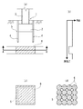
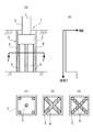
図1は基礎2の下層の地盤中の、基礎2の底面より広範囲の領域の全面、またはほぼ全面に地盤改良体6を構築した場合を示す。(a)は基礎2及び矢板4と地盤改良体6の関係を、(b)は深度に対応したN値の変化の様子を示す。ここに示すように地盤改良体6はN値が相対的に小さい(地盤強度が小さい)深度の範囲に集中的に構築されるが、そのN値が小さい範囲の一部の区間に、またはその範囲を挟んだ区間に亘って構築されることもある。(c)、(d)は(a)のA−A線の断面を示す。(c)は前記領域の全面に隙間なく地盤改良体6を構築した場合、(d)は円柱状の地盤改良体6を互いに接触、または重複させながら構築した場合である。
FIG. 1 shows a case where a
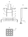
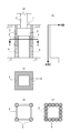
図2は基礎2の底面より広範囲の領域のほぼ全面に地盤改良体6を構築した場合を示す。(a)は基礎2及び矢板4と地盤改良体6の関係を、(b)は深度に対応したN値の変化の様子を示す。(c)は(a)のB−B線の断面を示す。ここでは前記領域の周辺部分を含めて格子状に、円柱状の地盤改良体6を互いに接触、または重複させながら構築している。
FIG. 2 shows a case where the
図3は基礎2の底面より広範囲の領域の周辺部分に地盤改良体6を構築した場合を示す。(a)は基礎2及び矢板4と地盤改良体6の関係を、(b)は深度に対応したN値の変化の様子を示す。(c)〜(e)は(a)のC−C線の断面を示す。(c)は前記領域の周辺部分に、周方向に連続的に地盤改良体6を構築した場合、(d)は前記周辺部分の隅角部にのみ円柱状の地盤改良体6を構築した場合、(e)は周方向に沿って円柱状の地盤改良体6を互いに接触、または重複させながら構築した場合である。
FIG. 3 shows a case where the
図1〜図3は地盤改良体6の下端が支持層に接している場合の例を示しているが、支持層の深度が例えば20mを超えるような場合には地盤改良体6が支持層に接しない状態で構築されることもある。その場合、地盤改良体6は沈下に対し、表面の摩擦力と先端の抵抗力によって抵抗する。
1 to 3 show an example in which the lower end of the
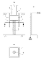
図4−(a)は図1−(a)の具体例として基礎2上に連続して上部構造3である橋脚を構築し、その上に橋桁を構築、または架設した場合を示している。(b)は柱状図とN値の関係を示す。ここでは地表面から地下18m程度の深度まで砂質土が存在し、その下に24m程度の深度まで粘性土が存在する地盤において、基礎2の底面の深度が5m、基礎2の幅が5mの場合に、10mの深度まで矢板4を挿入し、地下15m程度から24m程度までの範囲の区間に、基礎2底面の幅より広い、12m程度の幅に亘って円柱状の地盤改良体6を互いに接触させながら構築している。支持層は地下40mを超えた深度に存在している。
FIG. 4- (a) shows a case where a bridge pier which is the
図4−(a)に示す直接基礎1の施工手順例を図5−(a)〜(d)に示す。図5の場合、(a)に示すようにロッド8の先端に掘削攪拌翼7を有する地盤改良機を用いて地表面から地盤を掘削し、地盤改良体6の構築開始深度から地中に固化材液を吐出しながら掘削土と攪拌・混合し、地盤改良体6の構築終了深度まで到達したところで、固化材液の吐出を停止し、ロッド8を引き上げる、という作業を繰り返すことにより地盤改良体6が構築される。
Examples of construction procedures for the direct foundation 1 shown in FIG. 4- (a) are shown in FIGS. In the case of FIG. 5, the ground is excavated from the ground surface using a ground improvement machine having the
続いて(b)に示すように地表面から矢板4を挿入し、腹起しと切梁等の支保工9により矢板4の安定性を確保しながら矢板壁5を形成する一方、(c)に示すように矢板壁5内部の掘削土が排出される。(a)の地盤改良体6の構築時点で、地盤改良体6上の地盤は掘削攪拌翼7によって一旦、掘削され、緩められているため、ここでは改めて掘削を行う必要はない。
Subsequently, as shown in (b), the
その後、矢板壁5の内周面に基礎2との一体性を確保するための孔あき鋼板10等の鋼材やアンカー筋等を接合すると共に、根切り底に捨てコンクリート11を打設して基礎2の鉄筋を配筋し、矢板壁5の内部にコンクリートを打設することにより基礎2が構築される。更に(d)に示すように基礎2に連続して上部構造3を構築し、矢板壁5内の基礎2上に掘削土を埋め戻して直接基礎1の施工が終了する。
After that, steel material such as a
図6〜図9に示す直接基礎1は、地中に構築される構造物の基礎2を包囲するようにその周方向に隣接しながら、地中に基礎2の底面を超えた深度まで挿入される矢板4と、矢板4からなる矢板壁5で包囲された領域を含む領域に、基礎2の底面の深度から構築される地盤改良体6とを備えている。基礎2と上部構造3の構造、矢板4の種類、挿入深度、地盤改良体6の構築方法、並びに直接基礎1の施工手順等は図1〜図4に示す直接基礎1と同様である。
The direct foundation 1 shown in FIGS . 6 to 9 is inserted into the ground to a depth exceeding the bottom surface of the
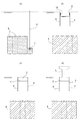
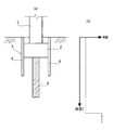
図6は矢板壁5で包囲された領域内の矢板壁5寄りの部分に地盤改良体6を構築した場合を示す。(a)は基礎2及び矢板4と地盤改良体6の関係を、(b)は深度に対応したN値の変化の様子を示す。(c)〜(e)は(a)のD−D線の断面を示す。(c)は矢板壁5で包囲された領域の隅角部に円柱状の地盤改良体6を構築した場合、(d)は前記領域の縁に沿って連続的に地盤改良体6を構築した場合、(e)は前記領域の縁に沿い、円柱状の地盤改良体6を互いに接触、または重複させながら構築した場合を示す。
FIG. 6 shows a case where the
図7は矢板壁5で包囲された領域の中心部分に地盤改良体6を構築した場合を示す。(c)は(a)のE−E線の断面を示す。ここでは前記領域の中心部分に、径の大きめの、1本の円柱状の地盤改良体6を構築しているが、小径の円柱状の地盤改良体6を多数集合させることもある。
FIG. 7 shows a case where the
図8は矢板壁5で包囲された領域の隅角部と中心部分に地盤改良体6を構築した場合を示す。(c)〜(e)は(a)のF−F線の断面を示す。(c)は矢板壁5で包囲された領域の隅角部と中心部に円柱状の地盤改良体6を構築した場合、(d)は隅角部と中心部を含む部分に連続的に地盤改良体6を構築した場合、(e)は(d)と同じく隅角部と中心部を含む部分に円柱状の地盤改良体6を互いに接触、または重複させながら構築した場合を示す。
FIG. 8 shows a case where the
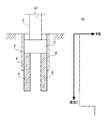
図9は矢板壁5の内側の領域に加え、外側の領域にも地盤改良体6を構築した場合、特に外側の地盤改良体6を基礎2の底面の深度より上の深度、例えば地表面まで構築した場合を示す。(c)〜(e)は(a)のG−G線の断面を示す。(c)は矢板壁5を挟んだ内側と外側の領域に連続的に地盤改良体6を構築した場合、(d)は矢板壁5の隅角部に円柱状の地盤改良体6を構築した場合、(e)は矢板壁5を挟んだ内側と外側の領域に円柱状の地盤改良体6を互いに接触、または重複させながら構築した場合を示す。
FIG. 9 shows that when the
図9では矢板壁5の外側の領域の地盤改良体6を地表面まで構築することで、矢板壁5が深度方向の全長に亘って地盤改良体6中に埋設される形になるため、矢板壁5の安定性と剛性が高まる利点がある。
In FIG. 9, since the
以上の図6〜図9の例では地盤改良体6の先端が支持層に到達している場合を示しているが、支持層の深度が大きく、例えば20mを超えるような場合には図10〜図13に示すように地盤改良体6の先端を支持層に到達させず、地盤改良体6の表面の摩擦力と先端の抵抗力によって上部構造3の荷重に抵抗させることもできる。図10〜図13はそれぞれ図6〜図9に対応している。
Although the example of the above FIG. 6 to FIG. 9 shows the case where the tip of the
1………矢板併用型直接基礎
2………基礎
3………上部構造
4………矢板
5………矢板壁
6………地盤改良体
7………掘削攪拌翼
8………ロッド
9………支保工
10……孔あき鋼板
11……捨てコンクリート
1 ……… Sheet combination type
Claims (5)
記基礎の底面を超えた深度まで挿入される矢板と、
前記矢板からなる矢板壁で包囲された領域に、前記基礎の底面の深度から柱状に構築され、前記領域の縁に沿って連続して並べて配置される地盤改良体とを備えることを特徴とする矢板併用型直接基礎。 A sheet pile inserted into the ground up to a depth beyond the bottom of the foundation, while adjoining the circumferential direction so as to surround the foundation of the structure to be built in the ground,
A realm that is surrounded by sheet pile wall made of the sheet piles are built columnar from the depth of the bottom surface of said base, and characterized in that it comprises a ground improvement body along the edge Ru are arranged in succession in the region A sheet pile combined direct base.
する請求項1に記載の矢板併用型直接基礎。 The sheet pile combined direct foundation according to claim 1 , wherein at least a section deeper than the foundation of the sheet pile wall is embedded in a ground improvement body.
ることを特徴とする請求項2に記載の矢板併用型直接基礎。 The ground pile combined direct foundation according to claim 2 , wherein the ground improvement body outside the sheet pile wall is constructed to a depth above the depth of the bottom surface of the foundation.
れかに記載の矢板併用型直接基礎。 The sheet pile improved direct foundation according to any one of claims 1 to 3 , wherein the ground improvement body reaches a support layer.
構造物の基礎が構築される地中に柱状に地盤改良体を構築する工程と、
前記基礎を包囲するようにその周方向に隣接させながら、前記基礎の底面を超えた深度まで矢板を挿入する工程と、
前記地盤改良体上の、前記矢板からなる矢板壁で包囲された領域に前記基礎を構築する工程とを含むことを特徴とする矢板併用型直接基礎の施工方法。 It is a construction method of a sheet pile combined type direct foundation according to any one of claims 1 to 4 ,
A step of constructing a ground improvement body in the shape of a pillar in the ground where the foundation of the structure is constructed ;
Inserting the sheet pile to a depth exceeding the bottom surface of the foundation while adjoining the circumferential direction so as to surround the foundation;
And a step of constructing the foundation in a region surrounded by a sheet pile wall made of the sheet pile on the ground improvement body.
Priority Applications (1)
| Application Number | Priority Date | Filing Date | Title |
|---|---|---|---|
| JP2005238100A JP5032012B2 (en) | 2005-08-19 | 2005-08-19 | Sheet pile combined direct foundation and its construction method |
Applications Claiming Priority (1)
| Application Number | Priority Date | Filing Date | Title |
|---|---|---|---|
| JP2005238100A JP5032012B2 (en) | 2005-08-19 | 2005-08-19 | Sheet pile combined direct foundation and its construction method |
Publications (2)
| Publication Number | Publication Date |
|---|---|
| JP2007051486A JP2007051486A (en) | 2007-03-01 |
| JP5032012B2 true JP5032012B2 (en) | 2012-09-26 |
Family
ID=37916101
Family Applications (1)
| Application Number | Title | Priority Date | Filing Date |
|---|---|---|---|
| JP2005238100A Expired - Fee Related JP5032012B2 (en) | 2005-08-19 | 2005-08-19 | Sheet pile combined direct foundation and its construction method |
Country Status (1)
| Country | Link |
|---|---|
| JP (1) | JP5032012B2 (en) |
Families Citing this family (7)
| Publication number | Priority date | Publication date | Assignee | Title |
|---|---|---|---|---|
| EP2063418A4 (en) | 2006-09-15 | 2010-12-15 | Panasonic Corp | Audio encoding device and audio encoding method |
| KR100862428B1 (en) * | 2007-07-12 | 2008-10-08 | 현대자동차주식회사 | Vehicle inclination preventing system using camber adjustment |
| JP4855359B2 (en) * | 2007-09-07 | 2012-01-18 | 新日本製鐵株式会社 | Steel sheet pile, steel sheet pile wall, and method for constructing steel sheet pile wall |
| JP5551943B2 (en) * | 2010-02-15 | 2014-07-16 | 株式会社竹中工務店 | Foundation structure using ground improvement body |
| JP5480744B2 (en) * | 2010-08-02 | 2014-04-23 | 公益財団法人鉄道総合技術研究所 | Foundation for structure and its construction method |
| CN102767173B (en) * | 2012-07-09 | 2014-05-07 | 河海大学 | High polymer material slurry filled discrete material pile composite foundation and construction method thereof |
| JP6969901B2 (en) * | 2017-05-24 | 2021-11-24 | 清水建設株式会社 | Co-fall suppression structure and caisson sinking method |
Family Cites Families (6)
| Publication number | Priority date | Publication date | Assignee | Title |
|---|---|---|---|---|
| JPH09125361A (en) * | 1994-03-29 | 1997-05-13 | Minami Kiso Kogyo Kk | Foundation soil improving technique for building |
| JPH093876A (en) * | 1995-06-26 | 1997-01-07 | Nippon Steel Corp | Soil cement underground continuous wall and building material made of steel therefor |
| JP3765000B2 (en) * | 1998-03-10 | 2006-04-12 | 株式会社竹中工務店 | Ground improvement foundation method for soft ground. |
| JP2005023670A (en) * | 2003-07-03 | 2005-01-27 | Shimizu Corp | Foundation construction of structure |
| JP2005023671A (en) * | 2003-07-03 | 2005-01-27 | Shimizu Corp | Settlement decrease structure of structure |
| JP4249046B2 (en) * | 2004-01-30 | 2009-04-02 | 財団法人鉄道総合技術研究所 | Support capacity increase method, sheet pile foundation construction method, sheet pile foundation, bridge |
-
2005
- 2005-08-19 JP JP2005238100A patent/JP5032012B2/en not_active Expired - Fee Related
Also Published As
| Publication number | Publication date |
|---|---|
| JP2007051486A (en) | 2007-03-01 |
Similar Documents
| Publication | Publication Date | Title |
|---|---|---|
| JP5032012B2 (en) | Sheet pile combined direct foundation and its construction method | |
| JP4794390B2 (en) | Pile foundation reinforcement structure and reinforcement method | |
| JP4281567B2 (en) | Reinforcement structure of existing pier foundation and reinforcement method of existing pier foundation | |
| JP2008190116A (en) | Liquefaction countermeasure structure of foundation ground of building | |
| JP5041223B2 (en) | Reinforcement method and structure of existing structure foundation | |
| JP3639294B1 (en) | Seismic reinforcement structure for structures | |
| JP4391292B2 (en) | Reinforcement structure for floating structures | |
| KR102223856B1 (en) | Foundation structure of waste landfill site and construction method thereof | |
| JP5296585B2 (en) | Soil cement improved structure and piled raft foundation | |
| JP3756385B2 (en) | Composite pile and its construction method | |
| JP3515567B1 (en) | Seismic reinforcement structure of structures | |
| JP3899094B2 (en) | Foundation reinforcement method for existing structures by press-fitting steel pipe piles | |
| JP5071852B2 (en) | Structure subsidence suppression structure | |
| JP2019127746A (en) | Flotation inhibition structure and inverted construction method | |
| JP2007277830A (en) | Core material, continuous underground wall, soil cement wall, continuous underground wall pile, soil cement wall pile, cast-in-place concrete pile, underground structure, and foundation structure of building | |
| JP2006077447A (en) | Foundation structure of construction | |
| JP3832845B2 (en) | Steel sheet pile combined direct foundation and construction method of steel sheet pile combined direct foundation | |
| JP2007032065A (en) | Pile foundation reinforcing structure | |
| JP4607485B2 (en) | Expanded caisson foundation structure and seismic reinforcement structure for existing caisson foundation | |
| JP7338995B2 (en) | Building foundation construction method and partition frame | |
| JP7359515B2 (en) | Liquefaction countermeasure structure for underground structures | |
| JP5053807B2 (en) | Ground improvement body construction method and ground improvement foundation structure | |
| JP2018071308A (en) | Restoration method of existing foundation, and restoration structure of existing foundation | |
| KR100374200B1 (en) | Reinforcement method fot tip of still pile | |
| JP2010209605A (en) | Piled-raft foundation |
Legal Events
| Date | Code | Title | Description |
|---|---|---|---|
| A621 | Written request for application examination |
Free format text: JAPANESE INTERMEDIATE CODE: A621 Effective date: 20071112 |
|
| A977 | Report on retrieval |
Free format text: JAPANESE INTERMEDIATE CODE: A971007 Effective date: 20100405 |
|
| A131 | Notification of reasons for refusal |
Free format text: JAPANESE INTERMEDIATE CODE: A131 Effective date: 20101124 |
|
| A521 | Written amendment |
Free format text: JAPANESE INTERMEDIATE CODE: A523 Effective date: 20110124 |
|
| A131 | Notification of reasons for refusal |
Free format text: JAPANESE INTERMEDIATE CODE: A131 Effective date: 20110906 |
|
| A521 | Written amendment |
Free format text: JAPANESE INTERMEDIATE CODE: A523 Effective date: 20111107 |
|
| TRDD | Decision of grant or rejection written | ||
| A01 | Written decision to grant a patent or to grant a registration (utility model) |
Free format text: JAPANESE INTERMEDIATE CODE: A01 Effective date: 20120619 |
|
| A01 | Written decision to grant a patent or to grant a registration (utility model) |
Free format text: JAPANESE INTERMEDIATE CODE: A01 |
|
| A61 | First payment of annual fees (during grant procedure) |
Free format text: JAPANESE INTERMEDIATE CODE: A61 Effective date: 20120628 |
|
| R150 | Certificate of patent or registration of utility model |
Free format text: JAPANESE INTERMEDIATE CODE: R150 |
|
| FPAY | Renewal fee payment (event date is renewal date of database) |
Free format text: PAYMENT UNTIL: 20150706 Year of fee payment: 3 |
|
| LAPS | Cancellation because of no payment of annual fees |