JP5025286B2 - Encoding device and decoding device - Google Patents
Encoding device and decoding device Download PDFInfo
- Publication number
- JP5025286B2 JP5025286B2 JP2007048279A JP2007048279A JP5025286B2 JP 5025286 B2 JP5025286 B2 JP 5025286B2 JP 2007048279 A JP2007048279 A JP 2007048279A JP 2007048279 A JP2007048279 A JP 2007048279A JP 5025286 B2 JP5025286 B2 JP 5025286B2
- Authority
- JP
- Japan
- Prior art keywords
- motion vector
- mvd
- selection information
- bits
- pmv
- Prior art date
- Legal status (The legal status is an assumption and is not a legal conclusion. Google has not performed a legal analysis and makes no representation as to the accuracy of the status listed.)
- Expired - Fee Related
Links
Images


Description
本発明は、所定のデータを予測符号化する符号化装置及び予測符号化された符号化データを復号する復号装置に関するものである。 The present invention relates to an encoding device that predictively encodes predetermined data and a decoding device that decodes predictive-encoded encoded data.
近年、映像符号化技術、映像符号化方式の発展はめざましく、なかでも、非特許文献1、2に記載される映像符号化方式は、その符号化効率の高さゆえに、さまざまな用途に幅広く応用されている。
これらの映像符号化方式においては、映像を構成する各静止画像(ピクチャ)を所定サイズ(16×16など)のブロックに分割し、前記ブロック単位で画面内予測方式、画面間予測方式と呼ばれる2つの予測方式を適宜切替えて予測符号化を行う。
ここで、予測符号化とは、所定の方法で符号化対象の画像についての予測画像を生成し、前記符号化対象の画像と前記予測画像との差分(差分情報)と、前記予測画像の生成方法についての情報(予測情報)とを符号化することにより、高い符号化効率を実現する符号化方法である。
また、画面内予測方式とは、所定ブロックの符号化の際、前記所定ブロックと同一ピクチャに属するブロックのうち、既に符号化済みのブロックについての再生画像を利用して、前記所定ブロックについての予測画像を生成する予測方式である。
一方、画面間予測方式とは、符号化の際、前記所定ブロックを含むピクチャ以前に符号化されたピクチャの再生画像(参照画像)を利用して、前記所定のブロックについての予測画像を生成する予測方式である。
In recent years, video coding technology and video coding schemes have been remarkably developed. Among them, the video coding schemes described in Non-Patent
In these video encoding schemes, each still image (picture) constituting a video is divided into blocks of a predetermined size (16 × 16, etc.), and each block is called an intra-screen prediction scheme or an inter-screen prediction scheme. Predictive coding is performed by appropriately switching between two prediction methods.
Here, predictive coding generates a predicted image for an image to be encoded by a predetermined method, generates a difference (difference information) between the image to be encoded and the predicted image, and generates the predicted image. This is an encoding method that realizes high encoding efficiency by encoding information (prediction information) about the method.
The intra prediction method is a method for predicting a predetermined block by using a reproduced image of an already encoded block among blocks belonging to the same picture as the predetermined block when the predetermined block is encoded. This is a prediction method for generating an image.
On the other hand, the inter-screen prediction method generates a predicted image for the predetermined block by using a reproduced image (reference image) of a picture encoded before the picture including the predetermined block at the time of encoding. This is a prediction method.
より具体的には、符号化対象のブロック(ブロック1)の内容が参照画像内の所定位置のブロック(ブロック2)の内容に近い場合、ブロック2からブロック1への平行移動量(動きベクトル)を画面間予測の予測情報とし、ブロック1とブロック2との内容の差分を差分情報として符号化する。
ブロック1の内容に最も近い内容を持つブロック2の位置を参照画像の中から見つけること(動き探索という)が、画面間予測符号化の符号化効率向上の観点で重要になる。
一般に、参照画像と符号化対象の画像の間に大きな変化(シーンチェンジなど)が発生しなければ、画面内予測を用いるより画面間予測を用いた方が高い符号化効率が得られる。
ただ、画面間予測方式における予測情報、すなわち動きベクトル情報は、通常水平方向と垂直方向の2成分を持ち、さらにブロック単位で符号化される。また、映像に動きが少なければ少ないほど、割り当てる符号量が短くなるように符号表が設計されることが多い。そのため、ブロック数が多い場合や動きが激しい場合、その符号量は無視できない。よって、動きベクトル情報についても、所定の方法で予測を行い、得られた予測ベクトル(以下PMVと呼ぶ)との差分ベクトル(以下MVDと呼ぶ)のみを符号化することにより、符号量を削減することが一般的である。このような動きベクトルの符号化方法は、非特許文献1、2に記載の映像符号化方式においても採用されている。
More specifically, when the content of the block to be encoded (block 1) is close to the content of the block (block 2) at a predetermined position in the reference image, the translation amount (motion vector) from
Finding the position of the
In general, if a large change (such as a scene change) does not occur between a reference image and an encoding target image, higher encoding efficiency can be obtained by using inter-screen prediction than by using intra-screen prediction.
However, the prediction information in the inter-screen prediction method, that is, motion vector information, normally has two components in the horizontal direction and the vertical direction, and is encoded in units of blocks. In addition, the code table is often designed so that the smaller the motion in the video, the shorter the code amount to be assigned. Therefore, when the number of blocks is large or the motion is intense, the code amount cannot be ignored. Therefore, the motion vector information is also predicted by a predetermined method, and only the difference vector (hereinafter referred to as MVD) from the obtained prediction vector (hereinafter referred to as PMV) is encoded, thereby reducing the code amount. It is common. Such a motion vector encoding method is also employed in the video encoding methods described in
図14は、非特許文献1に記載の映像符号化方式における、MVDの各成分の可変長符号表の一部である。左の列はMVDの各成分値、中央の列は前記MVDの各成分値に対応するビット列、右の列は前記ビット列の符号量(ビット数)を表す。本符号表から、MVDの各成分の絶対値(大きさ)が小さければ小さいほど、MVD、ひいては動きベクトルの符号化に掛かるビット数が小さいことが分かる。この関係は、符号表の中身は異なるものの、非特許文献2に記載の映像符号化方式においても成り立っている。また、図14に示す符号表からは、動きベクトルの大きさが2倍になると、符号量が2ビット増加するという関係性があることも分かる。紙面の都合上示せていないが、この関係性はMVDの大きさが20より大きいところにおいても常に成り立っている。
また、動きベクトルの予測方法としては、符号化対象のブロックと空間的あるいは時間的に近傍する複数の符号化済みブロックの動きベクトル情報をPMV候補とし、所定の方法で前記PMV候補の中から1つのPMVを選択する、という方法がある。
FIG. 14 is a part of a variable-length code table of each component of MVD in the video coding method described in Non-Patent
In addition, as a motion vector prediction method, motion vector information of a plurality of encoded blocks that are spatially or temporally adjacent to a block to be encoded is used as a PMV candidate, and one of the PMV candidates is selected by a predetermined method. There is a method of selecting one PMV.
図15は、符号化対象ブロックとその空間的近傍のブロックの一例を示すイメージ図である。Y01を現在の符号化対象ブロックとすると、Y02は符号化対象ブロックの左(位置Aと呼ぶ)に位置するブロック、Y03は符号化対象ブロックの上(位置B)に位置するブロック、Y04は符号化対象ブロックの右上(位置C)に位置するブロックである。ピクチャ内の各ブロックがラスタースキャン順に符号化される場合、ブロックY01の符号化を行う時点で、ブロックY02〜Y04は、いずれも既に符号化済みである。そのため、これらのブロックについての動きベクトルは、ブロックY01の動きベクトルの符号化におけるPMV候補として用いることが可能である。 FIG. 15 is an image diagram showing an example of an encoding target block and blocks in the spatial vicinity thereof. If Y01 is the current encoding target block, Y02 is a block located on the left of the encoding target block (referred to as position A), Y03 is a block located above the encoding target block (position B), and Y04 is a code. This block is located in the upper right (position C) of the conversion target block. When each block in the picture is encoded in the raster scan order, all of the blocks Y02 to Y04 are already encoded at the time of encoding the block Y01. Therefore, the motion vectors for these blocks can be used as PMV candidates in the coding of the motion vector of block Y01.
そして、例えば非特許文献1、2に記載の映像符号化方式では、ブロックY02〜Y04が全て画面間予測符号化されているとき、(例外はあるものの)基本的にこれら3つのブロックの動きベクトルのメジアンが、ブロックY01の動きベクトルの符号化におけるPMVとして選択される。ただし、前記3つのブロックの動きベクトルのうち、1つでも利用できない場合は、そのままではメジアンを求めることはできない。例えば、ブロックY01がピクチャの左端のブロックであった場合、ブロックY01の左に位置するブロックY02は存在しないため、利用できない。このような場合、例えば非特許文献1においては、位置Aのブロックの動きベクトルをゼロベクトルと仮定することでメジアンを求められるようにしている。一方、前記3つのブロックのうち2つのブロックの動きベクトルが利用できない場合は、残る1つのブロックの動きベクトルをPMVとする。その他にも例外はあるものの、いずれにせよ複数のPMV候補の中からPMVを特定する方法を示す情報を特に符号化することなく、PMV候補の利用可能状況などに応じた固定的な方法によりPMVは選択される。
For example, in the video encoding methods described in
ここでもし、メジアン固定ではなく、ブロック毎にMVD最小となるPMVを適切に選択することが出来れば、より効率的に動きベクトル情報を符号化出来ることは言うまでもない。しかし、前記選択のために、画面間予測符号化を行う全てのブロックにPMVの選択情報などを付与して符号化するとなると、それは却って符号化効率を低下させることにもつながりかねない。 In this case, it is needless to say that motion vector information can be encoded more efficiently if the PMV that minimizes the MVD can be appropriately selected for each block instead of being fixed to the median. However, if encoding is performed by adding PMV selection information or the like to all the blocks to be subjected to inter-frame predictive encoding for the selection, this may lead to a decrease in encoding efficiency.
このような状況に鑑み、特許文献1においては、動きベクトルの符号化の際、画面間予測符号化を行う全てのブロックに一律でPMVの選択情報を付与するのではなく、MVDの符号量削減が期待出来るブロックにのみ選択情報を付与する技術が提案されている。
具体的には、PMV候補間の分散を求め、その分散値が所定の閾値未満であれば選択情報は付与せず従来どおりメジアンをPMVとして選択し、そうでないときはMVDが最小となるPMVの選択を指示する選択情報を付与して符号化することにより、選択情報による符号量増加を抑えつつ、動きベクトル全体の符号化効率向上を図るという技術である。
なお、前記分散値DISは、以下の式によって求められる。
In view of such a situation, in
Specifically, the variance between the PMV candidates is obtained, and if the variance value is less than a predetermined threshold value, selection information is not given and the median is selected as the PMV as in the conventional case. Otherwise, the PMV that minimizes the MVD is selected. This is a technique for improving the coding efficiency of the entire motion vector while suppressing an increase in the code amount due to the selection information by adding selection information for instructing selection and encoding.
The variance value DIS is obtained by the following formula.
![]()
![]()
ここで、Nは、PMV候補の数で、MVi1、MVi2は、それぞれPMV候補の水平成分、垂直成分で、MED1、MED2は、それぞれPMV候補の水平成分、垂直成分のメジアンである。以下では、N=3の場合について考える。 Here, N is the number of PMV candidates, MVi1 and MVi2 are the horizontal component and vertical component of the PMV candidate, respectively, and MED1 and MED2 are the median of the horizontal component and vertical component of the PMV candidate, respectively. In the following, the case where N = 3 is considered.
図16は、3つのPMV候補から1つのPMVを選択するために付与する選択情報の可変長符号表の例である。選択情報は成分ごとに付与され、3つのPMV候補のメジアンを選択する場合はビット列「0」、メジアンよりも小さいものを選択する場合はビット列「10」、メジアンよりも大きいものを選択する場合はビット列「11」、をMVDとは別に符号化する。 FIG. 16 is an example of a variable-length code table of selection information provided for selecting one PMV from three PMV candidates. Selection information is given for each component. When selecting median of three PMV candidates, bit string “0” is selected. When selecting smaller than median, bit string “10” is selected. When selecting median larger than median, The bit string “11” is encoded separately from the MVD.
例えば、符号化対象ブロックY01の動きベクトルが(−8、−8)であるとし、近傍ブロックY02、Y03、Y04の動きベクトル、すなわちPMV候補がそれぞれ(−7、−7)、(−4、−4)、(−1、−1)である場合を考える(符号化パターン1)。このとき、PMV候補のメジアンは(−4、−4)となり、メジアンをPMVに選択した場合のMVDは(−4、−4)となる。図14に示す符号表により符号化することを考えると、(−4、−4)というMVDの符号化に掛かるビット数は、各成分ともに7ビットであるため、合計14ビットとなる。 For example, it is assumed that the motion vector of the encoding target block Y01 is (−8, −8), and the motion vectors of neighboring blocks Y02, Y03, Y04, that is, PMV candidates are (−7, −7), (−4, -4) and (-1, -1) are considered (coding pattern 1). At this time, the median of the PMV candidate is (−4, −4), and the MVD when the median is selected as PMV is (−4, −4). Considering that encoding is performed using the code table shown in FIG. 14, the number of bits required for MVD encoding (−4, −4) is 7 bits for each component, and is a total of 14 bits.
ここで、仮に前記所定の閾値がDIS1(4/3<DIS1≦12)であるとする。符号化パターン1における分散値DISは、式(1)より12と求められるから、DIS≧DIS1が成り立ち、選択情報の付与によるPMVの選択が可能となる。そこで、ブロックY02の動きベクトル(−7、−7)をPMVとして選択することで、MVDは(−1、−1)となり、その符号化に掛かるビット数は、図14に示す符号表から、合計6ビットとなる。しかし、3つのブロックY02〜Y04のうち、いずれの動きベクトルをPMVとして選択したかを明示するため、成分ごとに選択情報を付与する必要がある。図16の符号表に従うと、PMV(−7、−7)の各成分は、メジアン(−4、−4)と比べていずれも小さいため、2ビットのビット列「10」を成分ごとに付与することになる。結果、動きベクトルの符号化に掛かるビット数は合計10ビットとなり、固定的にメジアンをPMVとする場合に掛かる符号量14ビットと比べて、4ビットの符号を削減できたことになる。
Here, it is assumed that the predetermined threshold is DIS1 (4/3 <DIS1 ≦ 12). Since the variance value DIS in the
次に、符号化対象ブロックY01の動きベクトルが(−9、−9)であるとし、近傍ブロックY02、Y03、Y04の動きベクトル、すなわちPMV候補がそれぞれ(−5、−5)、(−4、−4)、(−3、−3)である場合を考える(符号化パターン2)。このときもPMV候補のメジアンは(−4、−4)となり、メジアンをPMVに選択した場合のMVDは(−5、−5)となる。図14に示す符号表により符号化することを考えると、(−5、−5)というMVDの符号化に掛かるビット数は、各成分ともに7ビットであるため、合計14ビットとなる。
符号化パターン2における分散値DISは、式(1)より4/3と求められるから、DIS<DIS1が成り立ち、選択情報の付与は行われず、固定的にPMV候補のメジアンがPMVとして選択されることになる。つまり、動きベクトルの符号化に掛かるビット数は依然合計14ビットのままで、符号量の削減はなされていない。
Next, it is assumed that the motion vector of the encoding target block Y01 is (−9, −9), and the motion vectors of neighboring blocks Y02, Y03, Y04, that is, PMV candidates are (−5, −5), (−4), respectively. -4, and -3, -3) (encoding pattern 2). Also at this time, the median of the PMV candidate is (−4, −4), and the MVD when the median is selected as PMV is (−5, −5). Considering encoding using the code table shown in FIG. 14, the number of bits required for MVD encoding (−5, −5) is 7 bits for each component, so that the total is 14 bits.
Since the variance value DIS in the
しかし、仮に符号化パターン2においても選択情報を付与するとすれば、最もMVDの大きさが小さくなる(−5、−5)をPMVとして選択することにより、MVDは(−4、−4)となる。しかし、その符号化に掛かるビット数は、図14に示す符号表から、合計14ビットとなり、固定的にPMV候補のメジアンをPMVとする場合と比べてなんら符号量の削減はなされていない。それどころか、実際にはMVDの14ビットに加えてさらに成分ごとに選択情報を付与しなければならないため、動きベクトル全体の符号量は逆に増大してしまう。
つまり、符号化パターン2においては、選択情報を付与せずに、固定的にPMV候補のメジアンをPMVとして選択する方法が最も動きベクトルの符号化に掛かるビット数を小さくできるのである。
However, if selection information is given also in the
That is, in the
一方、符号化対象ブロックY01の動きベクトルが(−15、−15)であるとし、近傍ブロックY02、Y03、Y04の動きベクトル、すなわちPMV候補が符号化パターン1と同様にそれぞれ(−7、−7)、(−4、−4)、(−1、−1)である場合を考える(符号化パターン3)。このときもPMV候補のメジアンは(−4、−4)となるため、メジアンをPMVに選択した場合のMVDは(−11、−11)となる。図14に示す符号表により符号化することを考えると、(−11、−11)というMVDの符号化に掛かるビット数は、各成分ともに9ビットであるため、合計18ビットとなる。 On the other hand, it is assumed that the motion vector of the encoding target block Y01 is (−15, −15), and the motion vectors of neighboring blocks Y02, Y03, Y04, that is, PMV candidates are (−7, − 7), (-4, -4), and (-1, -1) are considered (encoding pattern 3). At this time, the median of the PMV candidate is (−4, −4), and thus the MVD when the median is selected as PMV is (−11, −11). Considering that encoding is performed using the code table shown in FIG. 14, the number of bits required for MVD encoding of (-11, -11) is 9 bits for each component, so that the total is 18 bits.
PMV候補の内容は、符号化パターン3においても、符号化パターン1と同じであるから、分散値DISの値は12となる。よって、DIS≧DIS1が成立し、選択情報を付与してPMVを選択することが可能である。ここで、MVDの大きさが最小となるPMVの候補は、ブロックY02の動きベクトル(−7、−7)で、このときのMVDは(−8、−8)となり、その符号化に掛かるビット数は、図14に示す符号表から、合計18ビットとなる。また、選択されたPMVは符号化パターン1のときと同じなので、成分ごとに2ビットのビット列「10」が付与される。結果、動きベクトルの符号化に掛かるビット数は合計22ビットとなり、固定的にメジアンをPMVとする場合に掛かる符号量18ビットと比べて、逆に4ビット増えたことになる。
以上の説明から、特許文献1に記載の動きベクトル符号化装置によると、たとえPMV候補の内容が同一であっても、つまりPMV候補間の分散が同一であっても、符号化対象の動きベクトルの内容によって、符号量を削減できる場合と、逆に符号量を増大させてしまう場合の両方があることが分かる。
From the above description, according to the motion vector encoding device described in
本発明は、このような状況に鑑みてなされたもので、特許文献1に記載される従来技術と比べて、PMVの選択情報の付与・非付与の判定方法を改善し、符号量が増大するケースを極小化することで、より効率的に動きベクトルを符号化することができる符号化装置を提供すると共にその符号化装置により符号化された動きベクトル符号化データを正しく復号することが出来る復号装置を提供するものである。
The present invention has been made in view of such a situation. Compared with the prior art described in
上記課題を解決するため、第1の技術手段は、所定の動きベクトルの符号化に際し、既に符号化済みの所定のM個(Mは2以上の自然数)の動きベクトルを予測動きベクトル候補とし、前記予測動きベクトル候補の中から符号化に用いる予測動きベクトルを選択し、前記所定の動きベクトルと前記予測動きベクトルとの差分を符号化する符号化装置であって、前記所定の動きベクトルと前記予測動きベクトル候補との差分候補を求める差分計算部と、前記予測動きベクトル候補間の距離の符号化に必要な符号量と前記差分候補の符号化に必要な符号量との差を所定の閾値と比較し、予測動きベクトルの選択情報を付与するか否かを判定する選択情報付与判定部と、前記選択情報と前記差分候補の符号化に必要な符号量から、符号化する差分を選択し、前記差分の計算に用いる予測動きベクトルを選択する予測動きベクトル選択部と、前記差分を符号化する差分符号化部と、前記選択情報を付与する場合には前記選択情報を符号化する選択情報符号化部と、を備える符号化装置を特徴とする。 In order to solve the above-mentioned problem, the first technical means, when encoding a predetermined motion vector, uses predetermined M motion vectors (M is a natural number of 2 or more) already encoded as predicted motion vector candidates, An encoding apparatus that selects a prediction motion vector used for encoding from among the prediction motion vector candidates and encodes a difference between the predetermined motion vector and the prediction motion vector, the predetermined motion vector and the prediction motion vector A difference calculation unit for obtaining a difference candidate with a motion vector predictor candidate; and a difference between a code amount necessary for encoding a distance between the motion vector predictor candidates and a code amount required for encoding the difference candidate with a predetermined threshold compared to a determining selection information addition determining unit that determines whether to grant selection information of the prediction motion vector, the amount of code required for encoding the difference candidate with the selected information, the difference of encoding And-option, to encode the selection information in the case of applying the prediction motion vector selection unit for selecting a prediction motion vector to be used for calculating the difference, a difference encoding unit for encoding the difference, the selection information And a selection information encoding unit.
第2の技術手段は、第1の技術手段において、前記予測動きベクトル選択部は、前記選択情報付与判定部が前記選択情報を付与しないと判定した場合には、前記予測動きベクトル候補の中から所定の基準選択方法にて予測動きベクトルを選択することを特徴とする。
第3の技術手段は、第2の技術手段において、前記所定の基準選択方法とは、前記予測動きベクトル候補のメジアンを予測動きベクトルとして選択することであることを特徴とする。
A second technical means is the first technical means, wherein the prediction motion vector selection unit, when the selection information addition determining unit determines not to grant the selection information, from among the candidate predicted motion vector A predictive motion vector is selected by a predetermined reference selection method.
According to a third technical means, in the second technical means, the predetermined reference selection method is to select a median of the predicted motion vector candidates as a predicted motion vector.
第4の技術手段は、所定の動きベクトルの復号に際し、符号化されている差分を復号し、既に復号済みの所定のM個(Mは2以上の自然数)の動きベクトルを予測動きベクトル候補とし、前記予測動きベクトル候補の中から復号に用いる予測動きベクトルを選択し、前記差分と前記予測動きベクトルを足し合わせることで前記所定の動きベクトルを復号する復号装置であって、前記差分を復号する差分復号部と、前記差分の符号量と前記予測動きベクトル候補間の距離の符号化に必要な符号量との差を所定の閾値と比較し、予測動きベクトルの選択情報が存在するか否かを判定する選択情報存在判定部と、前記判定の結果が前記選択情報の存在を示す場合には前記選択情報を復号する選択情報復号部と、前記選択情報が存在する場合は、前記選択情報を利用して予測動きベクトルを決定する予測動きベクトル決定部と、を備える復号装置を特徴とする。 The fourth technical means decodes the encoded difference when decoding the predetermined motion vector, and uses predetermined M motion vectors (M is a natural number of 2 or more) already decoded as predicted motion vector candidates. A decoding device that selects a prediction motion vector used for decoding from the prediction motion vector candidates and decodes the predetermined motion vector by adding the difference and the prediction motion vector, and decodes the difference The difference decoding unit compares the difference between the code amount of the difference and the code amount necessary for encoding the distance between the prediction motion vector candidates with a predetermined threshold value, and whether or not there is prediction motion vector selection information. A selection information presence determination unit that determines the selection information, a selection information decoding unit that decodes the selection information when the determination result indicates the presence of the selection information, and A predicted motion vector determination unit that determines a prediction motion vector by using the-option information, and wherein the decoding device comprising a.
第5の技術手段は、第4の技術手段において、前記予測動きベクトル決定部は、前記選択情報が存在しない場合には前記予測動きベクトル候補の中から所定の基準選択方法にて予測動きベクトルを選択して決定することを特徴とする。
第6の技術手段は、前記所定の基準選択方法とは、前記予測動きベクトル候補のメジアンを予測動きベクトルとして選択することであることを特徴とする。
According to a fifth technical means, in the fourth technical means, the predicted motion vector determination unit determines a predicted motion vector by a predetermined reference selection method from the predicted motion vector candidates when the selection information does not exist. It is characterized by selecting and determining .
In a sixth technical means, the predetermined reference selection method is to select a median of the predicted motion vector candidates as a predicted motion vector.
本発明の符号化装置によれば、PMVの選択情報の付与・非付与の判定において、PMV候補だけでなく、さらにMVD候補の値も利用することで、PMVを選択することによるMVDの符号量削減効果の期待値をより正確に見積もることが出来るようになり、結果として、動きベクトル全体の符号量を削減出来るようになる。
また、本発明の復号装置によれば、まずMVDを復号し、続いてPMVの選択情報を復号することにより、本発明の符号化装置により効率的に符号化された動きベクトル符号化データを正しく復号することが出来るようになる。
According to the encoding apparatus of the present invention, in determining whether to assign or not give selection information of PMV, not only the PMV candidate but also the value of the MVD candidate is used, so that the code amount of MVD by selecting the PMV The expected value of the reduction effect can be estimated more accurately, and as a result, the code amount of the entire motion vector can be reduced.
Also, according to the decoding device of the present invention, the MVD is first decoded, and then the PMV selection information is decoded, so that the motion vector encoded data efficiently encoded by the encoding device of the present invention is correctly corrected. It can be decrypted.
以下に、本発明の各実施例での共通部分について、図面を用いて説明する。
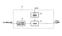
図1は、本発明の実施形態における符号化装置の構成の概要を示すブロック図である。
図において、11は、符号化装置、12は、動きベクトルを保持するためのメモリ部、13は、メモリ部12からM個(M>1)のPMV候補を抽出し、各PMV候補に所定のインデクスを付与した上で後段に出力する、PMV候補抽出部である。PMV候補抽出部13の具体的なインデクスの付与方法の例については後述する。
Hereinafter, common parts in the respective embodiments of the present invention will be described with reference to the drawings.
FIG. 1 is a block diagram showing an outline of the configuration of an encoding apparatus according to an embodiment of the present invention.
In the figure, 11 is an encoding device, 12 is a memory unit for holding a motion vector, 13 is extracted from the memory unit 12 M (M> 1) PMV candidates, and each PMV candidate has a predetermined value. This is a PMV candidate extraction unit that outputs an index after adding an index. An example of a specific index assignment method of the PMV
14は、動きベクトルとPMV候補を入力し、差分を計算、MVD候補として後段に出力する、MVD候補計算部である。動きベクトルの符号化において、PMV候補を決定すると、それに対応するMVD候補も一意に計算される。よって、PMV候補を特定することは、すなわち対応するMVD候補を特定することと等価である。また、その逆も真である。なお、MVD候補計算部14が出力するMVD候補には、対応するPMV候補に付与されているインデクスと同一のインデクスが付与されるものとする。
15は、MVD候補(復号時は「候補」ではなく正式なMVD)とM個のPMV候補を入力し、PMVの選択情報を付与するか否かを所定の方法により判定、その判定結果を選択情報付与情報として後段に出力する、MVD偏差評価部である。MVD偏差評価部15が出力する選択情報付与情報には、対応するMVD候補に付与されているインデクスと同一のインデクスが付与されるものとする。つまり、各PMV候補と、それに対応するMVD候補、選択情報付与情報には、それぞれ同一のインデクスが付与されることになる。MVD偏差評価部15は、本発明において中核をなすブロックであるため、後述する各実施例において詳細に説明する。
15 inputs MVD candidates (formal MVD instead of “candidate” at the time of decoding) and M PMV candidates, determines whether or not to add PMV selection information by a predetermined method, and selects the determination result This is an MVD deviation evaluation unit that outputs to the subsequent stage as information provision information. It is assumed that the same index as that assigned to the corresponding MVD candidate is assigned to the selection information addition information output by the MVD
16は、M個のMVD候補と各MVD候補に対応する選択情報付与情報を入力し、所定の方法にて実際の符号化に用いるPMVをM個のPMV候補の中から選択、そのインデクス(使用インデクス)を後段に出力する、インデクス選択部である。前記選択の方法の具体例としては、入力されたMVD候補と選択情報付与情報から動きベクトルの符号化コストを計算し、前記符号化コストが最小となるPMV候補をPMVとして選択する方法(PMV選択方法1)や、PMV候補を抽出したM個の符号化済みブロックのうち符号化対象ブロックと画像内容が最も似通っているブロックについての使用インデクスをそのまま符号化対象ブロックについての使用インデクスとする方法(PMV選択方法2)などが挙げられるが、動きベクトル情報などの符号化に掛かるビット数を小ならしめることが期待できるその他任意の方法で選択しても構わない。以下では、PMV選択方法1によって、PMVを選択するものとして説明する。PMV選択方法1における動きベクトルの符号化コストの具体例としては、動きベクトルの符号化に掛かるビット数や、MVDの絶対値などが挙げられる。以下では、動きベクトルの符号化コスト=動きベクトルの符号化に掛かるビット数として説明する。なお、説明を簡単にするため、インデクス選択部16においては、1つ1つの符号化対象ブロックそれぞれの符号化コストが最小となるようPMVを選択するものとしているが、複数の符号化対象ブロックについての符号化コストの「合計」が最小となるようそれぞれの符号化対象ブロックについてのPMVを選択するようにしてもよい。
16 inputs M MVD candidates and selection information addition information corresponding to each MVD candidate, selects a PMV to be used for actual encoding from M PMV candidates by a predetermined method, and uses its index (use This is an index selection unit that outputs (index) to the subsequent stage. As a specific example of the selection method, a method of calculating a motion vector encoding cost from an input MVD candidate and selection information addition information, and selecting a PMV candidate having the minimum encoding cost as a PMV (PMV selection) Method 1) or a method in which the used index for the block whose image content is most similar to the encoding target block among the M encoded blocks from which PMV candidates are extracted is used as the used index for the encoding target block as it is ( The PMV selection method 2) may be used, but any other method that can be expected to reduce the number of bits for encoding motion vector information or the like may be used. In the following description, it is assumed that the PMV is selected by the
17は、使用インデクスとM個のMVD候補を入力し、その使用インデクスによって指し示されるMVD候補を正式なMVDとして符号化、その符号化データを後段に出力する、MVD符号化部である。18は、使用インデクスとM個の選択情報付与情報を入力し、所定の方法でPMV選択情報を生成、符号化、その符号化データを後段に出力する、選択情報符号化部である。なお、必要に応じて、選択情報符号化部18の入力にM個のPMV候補を追加してもよい。
以下、MVDの符号化データ、または、PMVの選択情報の符号化データのことを総称して、動きベクトル符号化データと呼ぶ。
また、説明を簡単にするためと、前記従来技術の説明との整合を取るために、M=3とし、3つのPMV候補は、上記非特許文献1、2に記載の映像符号化方式と同様にして選択されるものとする。また、選択情報を付与しない場合に選択されるPMV(基準PMV候補と呼ぶ)は、以下においても、3つのPMV候補のメジアンであるとするが、固定的に位置Aについての動きベクトルとするなど、他の方法で基準PMV候補を選択しても構わない。
Hereinafter, the MVD encoded data or the encoded data of the PMV selection information is collectively referred to as motion vector encoded data.
In order to simplify the explanation and to match the explanation of the prior art, M = 3 and the three PMV candidates are the same as the video encoding methods described in
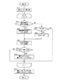
図5は、符号化装置11が、1つの動きベクトルを符号化する際の動作フローチャートの一例である。
動きベクトルの符号化処理開始後、まず、符号化対象の動きベクトルをメモリ部12にて保持する(ステップS1)。ステップS1にて保持される動きベクトルは、後の動きベクトルの符号化においてPMV候補として参照される。メモリ部12は、その実現に必要十分な容量を持つものとする。
次に、PMV候補抽出部13にて、メモリ部12に保持されている既に符号化済みの動きベクトルの中からPMV候補3つを選択、抽出する(ステップS2)。このとき、各PMV候補にはインデクスを付与する。例えば、抽出されたPMV候補のうち、メジアンと等しい値を持つものにはインデクス0、メジアンより小さい値を持つものにはインデクス1、メジアンより大きい値を持つものにはインデクス2、などというように、成分ごとに独立したインデクスの付与を行っておく(インデクス付与方法1)。なお、PMVの選択が、成分ごとではなく、ベクトルごとに出来れば十分という場合には、必ずしも成分ごとに独立したインデクスを付与する必要はなく、各PMV候補について1つのインデクスを付与するようにしてもよい。
FIG. 5 is an example of an operation flowchart when the
After starting the motion vector encoding process, first, the motion vector to be encoded is held in the memory unit 12 (step S1). The motion vector held in step S1 is referred to as a PMV candidate in the subsequent motion vector encoding. It is assumed that the
Next, the PMV
図11は、ベクトルごとにインデクスの付与をする方法の一例を示すイメージ図である。PMV候補のうち、水平成分、垂直成分ともに基準PMV候補と等しい値を持つものにはインデクス0を付与し、残りの2つのPMV候補のうち、位置的に左側にあるブロックの動きベクトルにはインデクス1、位置的に右側にあるブロックの動きベクトルにはインデクス2を付与する。図11に示すインデクスの付与方法を、インデクス付与方法2と命名する。インデクス付与方法2によりインデクスの付与を行うためには、水平成分、垂直成分ともに基準PMV候補と等しい値を持つ動きベクトルが、位置A、B、Cのうちのいずれかに存在しなければならない。一方、位置A、B、Cの動きベクトルのうち2つが水平成分、垂直成分がともに基準PMV候補と等しい値を持つ場合には、前記2つのPMV候補にインデクス0を付与し、残る1つのPMV候補に対し、インデクス1を付与するとよい。
FIG. 11 is an image diagram illustrating an example of a method for assigning an index for each vector. Among the PMV candidates, those having the same value as the reference PMV candidate in both the horizontal component and the vertical component are given
次に、MVD候補計算部14にて、各PMV候補に対応したMVD候補を導出する(ステップS3)。
次に、MVD偏差評価部15にて、選択情報の付与がコストに見合うか否かを、各MVD候補とM個のPMV候補に対する所定の演算の結果から判定し、選択情報付与情報を生成する(ステップS4)。
このように、本発明の符号化装置においては、選択情報の付与・非付与の判定のために、PMV候補だけでなく、MVDを用いる点で前記従来技術と異なっている。選択情報の付与・非付与の判定に、MVDを用いることの効果については、後述する各実施例において説明する。
なお、選択情報の付与・非付与の判定は、ベクトルごとに行ってもよいし、成分ごとに行ってもよい。前記判定を、ベクトルごとに行う方法を選択情報判定方法1、成分ごとに行う方法を選択情報判定方法2と命名する。以下では、特に記載がない限り、成分ごとに判定する(つまり選択情報判定方法2を採用する)ものとして説明する。
Next, the MVD
Next, the MVD
As described above, the encoding apparatus according to the present invention is different from the above-described prior art in that not only PMV candidates but also MVDs are used to determine whether or not selection information is given. The effect of using MVD for determination of whether or not selection information is given will be described in each example described later.
Whether the selection information is given or not may be determined for each vector or for each component. A method for performing the determination for each vector is named selection
ステップS4にて、3つのMVD候補の各候補についてそれぞれの選択情報付与情報を求めた後、インデクス選択部16にて、使用インデクスを選択する(ステップS5)。使用インデクスの選択についても、ベクトルごと、成分ごとのいずれかで行うことができるが、選択情報の付与・非付与の判定を選択情報判定方法2で行った場合には、使用インデクスの選択をベクトルごとに行うことはできない。なぜなら、一方の成分で選択情報を付与すると判定され、他方の成分で選択情報を付与しないと判定された場合、使用インデクスをベクトルで1つだけ選択することは必ずしもできないためである。前記選択を、ベクトルごとに行う方法をインデクス選択方法1、成分ごとに行う方法をインデクス選択方法2と命名する。以下では、特に記載がない限り、成分ごとに選択する(つまりインデクス選択方法2を採用する)ものとして説明する。なお、インデクス選択部16の具体的な動作フローの例は、図6を用いて後述する。
In step S4, the selection information giving information is obtained for each of the three MVD candidates, and then the
次に、MVD符号化部17にて、使用インデクスが指し示すMVD候補を正式なMVDとして符号化する(ステップS6)。
最後に、選択情報符号化部18にて、使用インデクスが指し示す選択情報付与情報が選択情報を付与することを示している場合のみ、3つのPMV候補のうちのいずれを正式なPMVとして選んだかを示す選択情報を符号化して(ステップS7)、処理を終了する。例えば、インデクス付与方法1に従ってPMV候補にインデクスが付与されているならば、図16の符号表を用いて、使用インデクスが0のときはビット列「0」、使用インデクスが1のときはビット列「10」、使用インデクスが2のときはビット列「11」、と符号化する(使用インデクス符号化方法1)。
Next, the
Finally, the selection
なお、3つのPMV候補のうち、2つが同値を持つ場合には、必ず前記同値がメジアンとなり、残るPMV候補は1つしかないため、インデクス1とインデクス2を区別する必要はない。そのため、使用インデクス0のときはビット列「0」、使用インデクス1または2のときはビット列「1」、と符号化することにより、選択情報の符号化に掛かるビット数の期待値をさらに削減することも可能である。
また、3つのPMV候補全てが一致する場合は、選択情報の符号化そのものが不要となるが、そもそもこの場合、MVD偏差評価部15にて、選択情報そのものを付与する必要がないと判定されるべきであろう。
When two of the three PMV candidates have the same value, the same value is always the median and there is only one remaining PMV candidate, so it is not necessary to distinguish between
If all three PMV candidates match, the encoding of the selection information itself is not necessary, but in this case, the MVD
一方、PMV候補が3つ全て存在しない場合を考える。例えば、符号化対象ブロックがピクチャの左端のブロックの場合、位置Aのブロックは存在せず、PMV候補が2つしか利用できない。このような場合、位置Aのブロックの動きベクトルをゼロベクトルとすることでPMV候補の数をあくまで3つとして扱うようにしてもよいが、利用できる2つのPMV候補のうちいずれか一方を基準PMV候補とした上で、2つのPMV候補を区別すべくインデクスを付与し、各インデクスに対応した選択情報を符号化するようにしてもよい。例えば、2つのPMV候補がそれぞれ属するブロックのうち、左側に位置するブロックについての動きベクトルを基準PMV候補とし、前記基準PMV候補にはインデクス0、もう一方のPMV候補にはインデクス1を付与するとした上で(インデクス付与方法3)、使用インデクス0のときはビット列「0」、使用インデクス1のときはビット列「1」、を符号化する方法が考えられる。
On the other hand, consider a case where all three PMV candidates do not exist. For example, when the encoding target block is the leftmost block of the picture, there is no block at position A, and only two PMV candidates can be used. In such a case, the number of PMV candidates may be handled as three by setting the motion vector of the block at position A to the zero vector, but either one of the two available PMV candidates is used as the reference PMV. After selecting candidates, an index may be assigned to distinguish two PMV candidates, and selection information corresponding to each index may be encoded. For example, a motion vector for a block located on the left side of two blocks to which two PMV candidates belong is set as a reference PMV candidate,
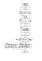
図6は、インデクス選択部16が、3つのMVD候補と各MVD候補に対応する選択情報付与情報を用いて、使用インデクスを選択する際の動作フローチャートの一例である。
処理開始後、まず、最小コスト値をコスト値が取りうる最大値に設定する(ステップS11)。
次に、ループカウンタであるiを0〜2まで変化させて、ステップS12〜S18の処理を繰り返し実行する。
FIG. 6 is an example of an operation flowchart when the
After the process starts, first, the minimum cost value is set to the maximum value that the cost value can take (step S11).
Next, i, which is a loop counter, is changed from 0 to 2, and the processes of steps S12 to S18 are repeatedly executed.
ステップS12では、iの値をインデクスに持つ選択情報付与情報が、選択情報の付与・非付与のいずれを示しているかを判定する。
「選択情報を付与」と判定された場合は(ステップS12/YES)、選択情報の符号化に掛かるコスト値を計算し(ステップS13)、後述するステップS16に移行する。
他方、「選択情報を非付与」と判定された場合は(ステップS12/NO)、ループカウンタiの値が0か否かを判定する(ステップS14)。
「i=0」と判定された場合は(ステップS14/YES)、コスト値を0として(ステップS15)、後述するステップS16に移行する。
他方、「i≠0」と判定された場合は(ステップS14/NO)、1回分のループ処理を完了する。
In step S12, it is determined whether the selection information giving information having the value of i indicates whether the selection information is given or not.
If it is determined that “selection information is given” (step S12 / YES), a cost value for encoding the selection information is calculated (step S13), and the process proceeds to step S16 described later.
On the other hand, when it is determined that “selection information is not given” (step S12 / NO), it is determined whether the value of the loop counter i is 0 (step S14).
If it is determined that “i = 0” (step S14 / YES), the cost value is set to 0 (step S15), and the process proceeds to step S16 described later.
On the other hand, if it is determined that “i ≠ 0” (step S14 / NO), one loop processing is completed.
ステップS16では、ステップS13またはステップS15にて設定されたコスト値に、MVDの符号化に掛かるコスト値を加算し、最終的に得られたコスト値と最小コスト値とを比較する(ステップS17)。
「コスト値<最小コスト値」と判定された場合は(ステップS17/YES)、最小コスト値をコスト値にて更新するとともに、最小コスト・インデクスをiに設定し(ステップS18)、1回分のループ処理を完了する。
他方、「コスト値≧最小コスト値」と判定された場合は(ステップS17/NO)、1回分のループ処理を完了する。
全てのループ処理が終了すると、その時点での最小コスト・インデクスを使用インデクスとして後段に出力し(ステップS19)、処理を終了する。
以上の流れにより、コスト最小で符号化することが出来るMVD候補のインデクスを選択できるのである。
In step S16, the cost value required for MVD encoding is added to the cost value set in step S13 or step S15, and the finally obtained cost value is compared with the minimum cost value (step S17). .
When it is determined that “cost value <minimum cost value” (step S17 / YES), the minimum cost value is updated with the cost value, and the minimum cost index is set to i (step S18). Complete the loop process.
On the other hand, if it is determined that “cost value ≧ minimum cost value” (step S17 / NO), one loop processing is completed.
When all the loop processes are completed, the minimum cost index at that time is output as a use index to the subsequent stage (step S19), and the process is terminated.
With the above flow, it is possible to select an index of an MVD candidate that can be encoded at a minimum cost.
ところで、MVDと対応する選択情報を1本のストリームに多重化して符号化する場合には、MVDを符号化した後に、対応する選択情報を符号化するようにしなければならない。
なぜなら、このように符号化された動きベクトルの復号時、選択情報が符号化されているか否かを判定するために、MVDが先に必要となるからである。
By the way, when the selection information corresponding to the MVD is multiplexed and encoded into one stream, the selection information corresponding to the MVD must be encoded after the MVD is encoded.
This is because MVD is first required to determine whether selection information is encoded when decoding a motion vector encoded in this way.
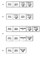
図10には、各MVDに対応する選択情報を多重化して符号化する際の形式(多重化形式)のいくつかの例を示す。
図10(A)、(B)は、選択情報判定方法2、インデクス選択方法2を採用する場合の、MVDと選択情報の多重化形式の例である。これらの多重化形式においては、PMVの選択情報が成分ごとに独立して符号化される。また、各成分のMVDを符号化した後に、対応する選択情報が符号化されているのが分かる。
FIG. 10 shows some examples of formats (multiplexing formats) when the selection information corresponding to each MVD is multiplexed and encoded.
FIGS. 10A and 10B are examples of multiplexing formats of MVD and selection information when the selection
図10(C)は、選択情報判定方法2、インデクス選択方法2を採用する場合の、MVDと選択情報の多重化形式の別の例である。図10(A)、(B)に示す多重化形式とは異なり、選択情報の付与に際して、まず、付与しようとする選択情報の水平成分、垂直成分の内容が同一であるか否かを判定し、その旨を同期選択情報として多重化する。前記判定の結果が同一でない場合は、値0の同期選択情報を多重化した上で、図10(A)と同様に、各成分の選択情報を多重化する(図10(C)上)。他方、前記判定の結果が同一である場合は、値1の同期選択情報を多重化した上で、各成分で共通の選択情報を1つだけ多重化する(図10(C)下)。
FIG. 10C is another example of the multiplexing format of MVD and selection information when the selection
なお、図10(A)、(C)については、選択情報判定方法1、インデクス選択方法2を採用する場合の、MVDと選択情報の多重化形式の例でもある。選択情報判定方法1においては、選択情報の付与・非付与の判定をベクトルごとに行う。そのため、MVD偏差評価部15における選択情報付与・非付与の判定に、MVDの水平成分、垂直成分の両方を利用可能にするために、MVDの両成分の後に、MVDの各成分に対応する選択情報を多重化することが望ましい。
10A and 10C are also examples of multiplexing formats of MVD and selection information when the selection
図10(D)は、選択情報判定方法1、インデクス選択方法1を採用する場合の、MVDと選択情報の多重化形式の例である。図10(A)とは異なり、インデクス選択方法1により、PMVの選択情報は、ベクトルに1つしか多重化されていない。
なお、選択情報判定方法2、インデクス選択方法1を採用する場合については例示しない。なぜなら、上述のとおり、選択情報の付与・非付与の判定を成分ごとに行うと、使用インデクスの選択をベクトルごとに行うことが必ずしも可能とは限らなくなるため、前記方法の組み合わせが採用されることは実際には起こりえないからである。
FIG. 10D is an example of a multiplexing format of MVD and selection information when the selection
Note that the case of adopting the selection
実際に使用される、選択情報判定方法、インデクス選択方法、および図10に示すようなMVDと選択情報の多重化方法を特定するためには、所定時間の映像(シーケンス)やピクチャなどのヘッダに前記各種方法を特定する情報を多重化するとよい。例えば、ピクチャのヘッダに前記情報を多重化する場合は、ピクチャ単位で前記各種方法を切替えることができるようになる。もちろん、逆に使用する前記各種方法を固定化することで、前記情報の多重化を回避しても構わない。 In order to specify the selection information determination method, the index selection method, and the MVD and selection information multiplexing method as shown in FIG. 10 that are actually used, the header of video (sequence) or picture for a predetermined time is used. Information specifying the various methods may be multiplexed. For example, when the information is multiplexed in the header of a picture, the various methods can be switched for each picture. Of course, the information multiplexing may be avoided by fixing the various methods used in reverse.
具体的な動きベクトルの復号の流れについては、以下で説明する。
図2は、本発明の実施形態における復号装置の構成の概要を示すブロック図である。
図示の復号装置21において、符号化装置11と同一のブロックには、同一符号を付し、その説明は省略する。22は、動きベクトル符号化データを入力し、MVDを復号、結果を後段に出力する、MVD復号部である。23は、選択情報付与情報と動きベクトル符号化データを入力として、PMVを特定するためのインデクスを導出、前記インデクスを後段に出力する、インデクス再生部である。24は、PMV候補とインデクスとMVDを入力とし、動きベクトルを再生し、後段に出力する、動きベクトル再生部である。動きベクトル再生部24はさらに、再生された動きベクトルをメモリ部12に保存する。
A specific flow of motion vector decoding will be described below.
FIG. 2 is a block diagram showing an outline of the configuration of the decoding device according to the embodiment of the present invention.
In the illustrated
図7は、復号装置21が、1つの動きベクトルを復号する際の動作フローチャートの一例である。
動きベクトルの復号処理開始後、まず、MVD復号部22にて、動きベクトル符号化データからMVDを抽出、復号する(ステップS21)。
次に、PMV候補抽出部13にて、メモリ部12に保持されている既に復号済みの動きベクトルの中からPMV候補3つを選択、抽出する(ステップS22)。このとき、各PMV候補にはインデクスを付与する。前記インデクスの付与の方法は、符号化処理におけるインデクスの付与の方法と同一であるとする。
FIG. 7 is an example of an operation flowchart when the
After starting the motion vector decoding process, first, the
Next, the PMV
次に、MVD偏差評価部15にて、PMVの選択情報が符号化されているか否かを、ステップS21で復号されたMVDとM個のPMV候補に対する所定の演算の結果から判定し、選択情報付与情報を生成する(ステップS23)。なお、前記所定の演算の内容は、符号化時のMVD偏差評価部15にて施される演算の内容と同一であるとする。
次に、インデクス再生部23にて、PMV候補を特定するためのインデクスを再生、出力する(ステップS24)。
インデクス再生部23は、ステップS23にて生成された選択情報付与情報がPMVの選択情報が符号化されていないことを示す場合は、動きベクトル符号化データからは何も読み出さず、無条件でPMV候補のメジアンを指し示すインデクスを後段に出力する。
Next, the MVD
Next, the
When the selection information addition information generated in step S23 indicates that the PMV selection information is not encoded, the
一方、前記選択情報付与情報がPMVの選択情報が符号化されていることを示す場合、インデクス再生部23は、まず動きベクトル符号化データから前記選択情報を読み出す。例えば、前記選択情報が図16の符号表を用いて符号化されている場合、動きベクトル符号化データからまず1ビット(ビット1)を読み出す。ビット1の内容が「0」の場合、前記選択情報の符号化ビット列を「0」として確定する。他方、ビット1の内容が「1」であった場合には、さらにもう1ビット(ビット2)を読み出し、ビット2の内容に応じて、前記選択情報の符号化ビット列を「10」または「11」として確定する。そして、インデクス再生部23は、読み出された選択情報のビット列に応じて、PMV候補を特定するインデクスを再生し、出力する。例えば、符号化装置11が、インデクス付与方法1に従ってPMV候補にインデクスを付与していたのであれば、符号化時とは逆に、符号化ビット列「0」はインデクス0、符号化ビット列「10」はインデクス1、符号化ビット列「11」はインデクス2、とすることで、符号化時における使用インデクスを再生できることになる。
On the other hand, when the selection information addition information indicates that PMV selection information is encoded, the
次に、動きベクトル再生部24は、インデクス再生部23が出力するインデクスにより、PMV候補抽出部13が出力するPMV候補の中から動きベクトルの再生に用いるPMVを特定し、MVD復号部22が出力するMVDに前記PMVを加算することで、動きベクトルを再生、出力する(ステップS25)。
最後に、ステップS25にて再生された動きベクトルを、以降の動きベクトル再生におけるPMV候補として再利用するため、メモリ部12に保持して処理を終了する(ステップS26)。
Next, the motion
Finally, in order to reuse the motion vector reproduced in step S25 as a PMV candidate in the subsequent motion vector reproduction, the processing is ended by holding it in the memory unit 12 (step S26).
以下の各実施例においては、MVD偏差評価部15について具体的な動作の例を挙げることにより、符号化装置11が、如何にして前記従来技術よりも動きベクトルの符号化に掛かるビット数を削減できるかを説明する。また、復号装置21が、如何にして符号化装置11が出力する動きベクトル符号化データを正しく復号するのかを説明する。
In each of the following embodiments, an example of a specific operation of the MVD
<実施例1>
まず、本発明の実施例1としての符号化装置について説明する。なお、本実施例における符号化装置の構成の概要は図1と同様であり、その動作の概要についても既に説明したとおりなので、ここでは、MVD偏差評価部15の動作の詳細に限って説明を行うこととする。
図3は、上述した符号化装置11、復号装置21における、MVD偏差評価部15のより詳細な構成を示すブロック図である。図3において、31は、M個のPMV候補を入力し、所定の方法でPMV候補の偏差(PMV偏差)を計算し、結果を後段に出力する、PMV候補偏差計算部である。なお、本発明の記載において「偏差」とは、標準となる数値からのばらつき、のことを指す。PMV候補における前記標準とは、例えば、メジアンなどが妥当であろう。32は、MVD候補(復号時は「候補」ではなく正式なMVD)を入力し、所定の方法でMVDの値をPMV候補の偏差と同一オーダーの値に変換し、後段に出力する、MVD変換部である。以下、変換されたMVDの値を変換MVDと呼ぶ。33は、PMV偏差と変換MVDを入力とし、両者の差分を所定の閾値と比較、前記比較結果に基づいて選択情報の付与・非付与を判定し、選択情報付与情報を生成、出力する、比較部である。
<Example 1>
First, an encoding apparatus as
FIG. 3 is a block diagram illustrating a more detailed configuration of the MVD
図8は、図3に示すMVD偏差評価部15が、1つのMVD候補(復号時は「候補」ではなく正式なMVD)とM個のPMV候補から、選択情報の付与・非付与を判定する際の動作フローチャートである。
処理開始後、まず、PMV候補偏差計算部31にて、PMV偏差を計算する(ステップS31)。具体的には、PMV候補のメジアンと前記メジアンから最も離れたPMV候補との差分を導出し、前記差分をMVDの符号表で符号化するのに掛かるビット数を以って、PMV偏差とする方法などが挙げられる(PMV偏差計算方法1)。その他、前記従来技術と同様PMV候補の分散、PMV候補の標準偏差、PMV候補の最大と最小との差分、あるいは前記差分をMVDの符号表で符号化するのに掛かるビット数など、PMV候補間のばらつきを表現する値であれば、何をPMV偏差としても構わない。以下では、PMV偏差計算方法1によりPMV偏差を計算することを前提に説明を行う。
8, the MVD
After the start of processing, first, the PMV candidate
次に、MVD変換部32にて、MVDをPMV偏差と同じ単位に変換する(ステップS32)。PMV偏差計算方法1によりPMV偏差を求めるのなら、前記変換とは、すなわち単にMVDの符号化に掛かるビット数を求める、ということと等価である。つまり、MVDの符号化に掛かるビット数こそが、変換MVDということになる。
次に、比較部33にて、PMV偏差と変換MVDの差を求め、所定の閾値THR1以上か否かを判定する(ステップS33)。
前記判定結果が「閾値THR1未満」の場合は(ステップS33/NO)、選択情報の非付与を示す選択情報付与情報を出力し(ステップS34)、処理を終了する。
他方、前記判定結果が「閾値THR1以上」の場合は(ステップS33/YES)、選択情報の付与を示す選択情報付与情報を出力し(ステップS35)、処理を終了する。
1つの動きベクトルの符号化において、図8に示す動作フローチャートの処理が、3つのMVD候補それぞれを入力として呼び出される。
Next, the
Next, the
When the determination result is “less than threshold value THR1” (step S33 / NO), selection information addition information indicating non-attachment of selection information is output (step S34), and the process ends.
On the other hand, when the determination result is “threshold value THR1 or more” (step S33 / YES), selection information addition information indicating the addition of selection information is output (step S35), and the process ends.
In encoding one motion vector, the process of the operation flowchart shown in FIG. 8 is called with each of the three MVD candidates as input.
ここで、本発明の実施形態として示した符号化装置11により、実際に動きベクトルを符号化する場合を考える。なお、以下では、閾値THR1の値を「2ビット」として説明する。まず、前記従来技術の説明における符号化パターン1について考える。符号化パターン1においては、符号化対象の動きベクトル、各PMV候補ともに、それぞれの水平成分、垂直成分の値が等しいため、いずれの成分についても同じ処理が施されることになる。よって以下では、一方の成分だけを抽出して説明を行う。
Here, consider a case where a motion vector is actually encoded by the
PMV偏差計算方法1によると、PMV候補のメジアンは−4、メジアンから最も離れたPMV候補は−7(あるいは−1)であり、差分は−3(あるいは3)、この差分を図14に示す符号表で符号化すると5ビット所要するため、PMV偏差は「5ビット」となる。
インデクス付与方法1に従って、PMV候補にインデクスが付与されているとするなら、インデクス0、1、2のPMV候補は、それぞれ−4、−7、−1である。また、符号化対象の動きベクトルは−8であるから、対応するMVD候補は、それぞれ−4、−1、−7となる。
According to the PMV
If indexes are assigned to PMV candidates according to the
インデクス0のMVD候補「−4」について、図8に示すフローチャートの処理を呼び出すと、変換MVDは、図14に示す符号表より、「7ビット」となる。また、ステップS33の計算結果は−2ビット(<THR1)となるため、図3のMVD偏差評価部15は、選択情報の「非付与」を示す選択情報付与情報を出力する。
インデクス1のMVD候補「−1」について、図8に示すフローチャートの処理を呼び出すと、変換MVDは、図14に示す符号表より、「3ビット」となる。また、ステップS33の計算結果は2ビット(≧THR1)となるため、図3のMVD偏差評価部15は、選択情報の「付与」を示す選択情報付与情報を出力する。
インデクス2のMVD候補「−7」について、図8に示すフローチャートの処理を呼び出すと、変換MVDは、図14に示す符号表より、「7ビット」となる。また、ステップS33の計算結果は−2ビット(<THR1)となるため、図3のMVD偏差評価部15は、選択情報の「非付与」を示す選択情報付与情報を出力する。
When the process of the flowchart shown in FIG. 8 is called for the MVD candidate “−4” of
When the processing of the flowchart shown in FIG. 8 is called for the MVD candidate “−1” of
When the process of the flowchart shown in FIG. 8 is called for the MVD candidate “−7” of
上記の結果を受けて、図6に示すフローチャートの処理を、コスト=符号化に掛かるビット数、として呼び出すと、使用インデクスは「1」で、そのときのMVDと選択情報の合計コストは「5ビット」となり、水平、垂直の2成分の合計では「10ビット」となる。これは、固定的にメジアンをPMVとする場合の「14ビット」に比べて、前記従来技術と同様「4ビット」の符号量削減効果が得られたことを意味する。
図12(A)は、符号化パターン1についての動きベクトル符号化において、図10(A)に示す多重化形式で出力した場合の動きベクトル符号化データの例である。
When the processing of the flowchart shown in FIG. 6 is called as the cost = the number of bits required for encoding in response to the above result, the used index is “1”, and the total cost of the MVD and the selection information at that time is “5”. “Bit”, and the total of the two horizontal and vertical components is “10 bits”. This means that, compared to “14 bits” when the median is fixedly set to PMV, the code amount reduction effect of “4 bits” is obtained as in the conventional technique.
FIG. 12A shows an example of motion vector encoded data when output in the multiplexed format shown in FIG. 10A in the motion vector encoding for
次に、前記従来技術の説明における符号化パターン2について考える。
符号化パターン2においては、符号化対象の動きベクトル、各PMV候補ともに、それぞれの水平成分、垂直成分の値が等しいため、いずれの成分についても同じ処理が施されることになる。よって以下では、一方の成分だけを抽出して説明を行う。
PMV偏差計算方法1によると、PMV候補のメジアンは−4、メジアンから最も離れたPMV候補は−5(あるいは−3)であり、差分は−1(あるいは1)、この差分を図14に示す符号表で符号化すると3ビット所要するため、PMV偏差は「3ビット」となる。
インデクス付与方法1に従って、PMV候補にインデクスが付与されているとするなら、インデクス0、1、2のPMV候補は、それぞれ−4、−5、−3である。また、符号化対象の動きベクトルは−9であるから、対応するMVD候補は、それぞれ−5、−4、−6となる。
Next, consider the
In
According to the PMV
If indexes are assigned to PMV candidates according to the
インデクス0のMVD候補「−5」について、図8に示すフローチャートの処理を呼び出すと、変換MVDは、図14に示す符号表より、「7ビット」となる。また、ステップS33の計算結果は−4ビット(<THR1)となるため、図3のMVD偏差評価部15は、選択情報の「非付与」を示す選択情報付与情報を出力する。
インデクス1のMVD候補「−4」について、図8に示すフローチャートの処理を呼び出すと、変換MVDは、図14に示す符号表より、「7ビット」となる。また、ステップS33の計算結果は−4ビット(<THR1)となるため、図3のMVD偏差評価部15は、選択情報の「非付与」を示す選択情報付与情報を出力する。
インデクス2のMVD候補「−6」について、図8に示すフローチャートの処理を呼び出すと、変換MVDは、図14に示す符号表より、「7ビット」となる。また、ステップS33の計算結果は−4ビット(<THR1)となるため、図3のMVD偏差評価部15は、選択情報の「非付与」を示す選択情報付与情報を出力する。
When the process of the flowchart shown in FIG. 8 is called for the MVD candidate “−5” of
When the process of the flowchart shown in FIG. 8 is called for the MVD candidate “−4” of
When the process of the flowchart shown in FIG. 8 is called for the MVD candidate “−6” of
上記の結果を受けて、図6に示すフローチャートの処理を、コスト=符号化に掛かるビット数、として呼び出すと、使用インデクスは「0」で、そのときのMVDと選択情報の合計コスト(このケースでは選択情報は0ビット)は「7ビット」となり、水平、垂直の2成分の合計では「14ビット」となる。これは、固定的にメジアンをPMVとする場合と同じで、前記従来技術とも同じ結果である。
図12(B)は、符号化パターン2についての動きベクトル符号化において、図10(A)に示す多重化形式で出力した動きベクトルの符号化データの例である。選択情報は付与されないため、MVDの水平成分、垂直成分のみが多重化されている。
When the processing of the flowchart shown in FIG. 6 is called as the cost = the number of bits required for encoding based on the above result, the used index is “0”, and the total cost of the MVD and selection information at this time (in this case) In this case, the selection information is 0 bit) is “7 bits”, and the total of the two horizontal and vertical components is “14 bits”. This is the same as the case where the median is fixedly set to PMV, and the same result as in the prior art.
FIG. 12B is an example of motion vector encoded data output in the multiplexing format shown in FIG. 10A in the motion vector encoding for the
次に、前記従来技術の説明における符号化パターン3について考える。
符号化パターン3においても、符号化対象の動きベクトル、各PMV候補ともに、それぞれの水平成分、垂直成分の値が等しいため、いずれの成分についても同じ処理が施されることになる。よって以下では、一方の成分だけを抽出して説明を行う。
PMV偏差については、PMV候補の内容が符号化パターン1と全く同じであるため、「5ビット」となる。
インデクス付与方法1に従って、PMV候補にインデクスが付与されているとするなら、インデクス0、1、2のPMV候補は、それぞれ−4、−7、−1である。また、対応するMVD候補は、それぞれ−11、−8、−14となる。
Next, consider the
Also in the
The PMV deviation is “5 bits” because the content of the PMV candidate is exactly the same as that of the
If indexes are assigned to PMV candidates according to the
インデクス0のMVD候補「−11」について、図8に示すフローチャートの処理を呼び出すと、変換MVDは、図14に示す符号表より、「9ビット」となる。また、ステップS33の計算結果は−4ビット(<THR1)となるため、図3のMVD偏差評価部15は、選択情報の「非付与」を示す選択情報付与情報を出力する。
インデクス1のMVD候補「−8」について、図8に示すフローチャートの処理を呼び出すと、変換MVDは、図14に示す符号表より、「9ビット」となる。また、ステップS33の計算結果は−4ビット(<THR1)となるため、図3のMVD偏差評価部15は、選択情報の「非付与」を示す選択情報付与情報を出力する。
インデクス2のMVD候補「−14」について、図8に示すフローチャートの処理を呼び出すと、変換MVDは、図14に示す符号表より、「9ビット」となる。また、ステップS33の計算結果は−4ビット(<THR1)となるため、図3のMVD偏差評価部15は、選択情報の「非付与」を示す選択情報付与情報を出力する。
When the process of the flowchart shown in FIG. 8 is called for the MVD candidate “−11” of
When the process of the flowchart shown in FIG. 8 is called for the MVD candidate “−8” of
When the process of the flowchart shown in FIG. 8 is called for the MVD candidate “−14” of
上記の結果を受けて、図6に示すフローチャートの処理を、コスト=符号化に掛かるビット数、として呼び出すと、使用インデクスは「0」で、そのときのMVDと選択情報の合計コスト(このケースでは選択情報は0ビット)は「9ビット」となり、水平、垂直の2成分の合計では「18ビット」となる。これは、固定的にメジアンをPMVとする場合と同じ符号量となる。このことは、前記従来技術によると逆に符号量が増大していた問題を解決していることになる。
図12(C)は、符号化パターン3についての動きベクトル符号化において、図10(A)に示す多重化形式で出力した動きベクトル符号化データの例である。選択情報は付与されないため、MVDの水平成分、垂直成分のみが多重化されている。
When the processing of the flowchart shown in FIG. 6 is called as the cost = the number of bits required for encoding in response to the above result, the used index is “0”, and the total cost of the MVD and selection information at this time (in this case In this case, the selection information is 0 bits) is “9 bits”, and the total of the two horizontal and vertical components is “18 bits”. This is the same code amount as when the median is fixed to PMV. This solves the problem that the code amount is increased according to the prior art.
FIG. 12C is an example of motion vector encoded data output in the multiplexing format shown in FIG. 10A in the motion vector encoding for the
以上、選択情報判定方法2、インデクス選択方法2を採用するケースについて説明してきたが、選択情報の付与・非付与の判定、選択情報の多重化などを、成分単位に行うかベクトル単位に行うか、だけの違いであり、同様の手法を他のパターンに対して適用した場合でも、同様の効果が得られることはいうまでもない。ただし、選択情報の付与・非付与に用いられる閾値THR1の最適な値は、各パターンに応じて異なるため、適切に設定する必要がある。例えば、成分単位で処理する場合と、ベクトル単位で処理する場合では、前者の方が一般的に小さな閾値THR1を設定してやる必要があることはいうまでもない。
The case where the selection
なお、いずれの選択情報判定方法、インデクス選択方法を採用する場合であっても、実際に閾値THR1を設定する際には、特定の動きベクトルの符号化パターンでのみ符号化効率向上の効果がある値を設定するのではなく、実際の映像を符号化した際に発生する符号化データをトータルで極小化出来るような値に設定することが望ましい。このような値は、例えば、さまざまな映像について、閾値THR1を変えながら符号化を試行することで特定することが可能である。 Note that, regardless of which selection information determination method and index selection method are employed, when the threshold value THR1 is actually set, there is an effect of improving the coding efficiency only with the coding pattern of a specific motion vector. Instead of setting a value, it is desirable to set the value so that encoded data generated when an actual video is encoded can be minimized in total. Such a value can be specified by, for example, trying to encode various videos while changing the threshold value THR1.
以上の説明から、本発明の実施例1に記載の符号化装置によれば、PMVの選択情報の付与・非付与の判定において、前記従来技術のようにPMV候補だけを利用するのではなく、さらにMVD候補の値をも利用することで、PMVを選択することによるMVDの符号量削減効果の期待値をより正確に見積もることが出来るようになり、結果として、動きベクトル全体の符号量を削減出来るようになる。 From the above description, according to the encoding device described in the first embodiment of the present invention, instead of using only the PMV candidates as in the above-described prior art, in the determination of the grant / non-assignment of the PMV selection information, Furthermore, by using the value of the MVD candidate, the expected value of the MVD code amount reduction effect by selecting the PMV can be estimated more accurately, and as a result, the code amount of the entire motion vector is reduced. become able to do.
<実施例2>
次に、本発明の実施例2としての復号装置について説明する。なお、本実施例における復号装置の構成の概要を示すブロック図は、図2に示すとおりであり、また、同復号装置におけるMVD偏差評価部は図3にそれぞれ示したとおりである。それらの動作の概要についても既述したとおりなので説明は省略し、ここでは、本発明の実施例1に記載の符号化装置によって符号化された図12に示す動きベクトル符号化データが、本実施例の復号装置によって正しく復号できることを証明する。
<Example 2>
Next, a decoding apparatus as
まず、図12(A)で示される動きベクトル符号化データを復号することを考える。復号処理開始後、まず、MVD復号部22にて、MVDの水平成分、垂直成分を復号する。復号に際しては、図14に示す符号表を用いる。すると、MVD(−1、−1)が得られる。
次に、PMV候補抽出部13にて、PMV候補3つを選択、抽出する。ここで、既に復号済みの動きベクトルが正しいものであると仮定すると、符号化時と同様、インデクス付与方法1に従ってインデクス0、1、2が付与されるPMV候補はそれぞれ(−4、−4)、(−7、−7)、(−1、−1)となる。
ここで、MVD、各PMV候補ともに、それぞれの水平成分、垂直成分の値が等しいため、いずれの成分についても同じ処理が施されることになる。よって以下では、一方の成分だけを抽出して説明を行う。
First, consider decoding the motion vector encoded data shown in FIG. After starting the decoding process, first, the
Next, the PMV
Here, since both the MVD and each PMV candidate have the same horizontal component and vertical component values, the same processing is performed for both components. Therefore, in the following, only one component will be extracted and described.
次に、MVD偏差評価部15にて、上記PMV候補と上記MVDを用いて、図8に示すフローチャートの処理を呼び出す。PMV偏差計算方法1によると得られるPMV偏差は「5ビット」、図14に示す符号表によるとMVD「−1」についての変換MVDは「3ビット」となり、PMV偏差−変換MVDは、「2ビット」となる。この値を、本発明の実施例1における符号化装置でも用いた閾値THR1=2ビットと比較すると、PMV偏差−変換MVD≧閾値THR1、が成立し、結果、PMV候補を選択する選択情報は符号化されていると判定される。
Next, the MVD
次に、インデクス再生部23にて、インデクスを再生する。前記判定において、PMV候補を選択する選択情報が符号化されていることが分かったので、図16に示す符号表から、メジアンより小さいPMV候補を選択するインデクス、すなわちインデクス1がPMV候補を特定するインデクスとして得られる。
動きベクトル再生部24は、インデクス1のPMV候補「−7」と、MVD「−1」とを加算することにより、動きベクトル「−8」(水平成分、垂直成分とも)を再生する。
この再生された動きベクトルは、本発明の実施例1に記載の符号化装置が、図12(A)に示す動きベクトル符号化データを生成、出力した際の、入力動きベクトルと合致する。
Next, the
The motion
This reproduced motion vector matches the input motion vector when the encoding apparatus according to the first embodiment of the present invention generates and outputs the motion vector encoded data shown in FIG.
次に、図12(B)で示される動きベクトル符号化データを復号することを考える。
復号処理開始後、まず、MVD復号部22にて、MVDの水平成分、垂直成分を復号する。復号に際しては、図14に示す符号表を用いる。すると、MVD(−5、−5)が得られる。
次に、PMV候補抽出部13にて、PMV候補3つを選択、抽出する。ここで、既に復号済みの動きベクトルが正しいものであると仮定すると、符号化時と同様、インデクス付与方法1に従ってインデクス0、1、2が付与されるPMV候補はそれぞれ(−4、−4)、(−5、−5)、(−3、−3)となる。
ここで、MVD、各PMV候補ともに、それぞれの水平成分、垂直成分の値が等しいため、いずれの成分についても同じ処理が施されることになる。よって以下では、一方の成分だけを抽出して説明を行う。
Next, consider decoding the motion vector encoded data shown in FIG.
After starting the decoding process, first, the
Next, the PMV
Here, since both the MVD and each PMV candidate have the same horizontal component and vertical component values, the same processing is performed for both components. Therefore, in the following, only one component will be extracted and described.
次に、MVD偏差評価部15にて、上記PMV候補と上記MVDを用いて、図8に示すフローチャートの処理を呼び出す。PMV偏差計算方法1によると得られるPMV偏差は「3ビット」、図14に示す符号表によるとMVD「−5」についての変換MVDは「7ビット」となり、PMV偏差−変換MVDは、「−4ビット」となる。この値を、本発明の実施例1における符号化装置でも用いた閾値THR1=2ビットと比較すると、PMV偏差−変換MVD<閾値THR1、が成立し、結果、PMV候補を選択する選択情報は符号化されていないと判定される。
次に、インデクス再生部23にて、インデクスを再生する。前記判定において、PMV候補を選択する選択情報が符号化されていないことが分かったので、PMV候補のメジアンを選択するインデクス0がPMV候補を特定するインデクスとして得られる。
動きベクトル再生部24は、インデクス0のPMV候補「−4」と、MVD「−5」とを加算することにより、動きベクトル「−9」(水平成分、垂直成分とも)を再生する。
この再生された動きベクトルは、本発明の実施例1に記載の符号化装置が、図12(B)に示す動きベクトル符号化データを生成、出力した際の、入力動きベクトルと合致する。
Next, the MVD
Next, the
The motion
This reproduced motion vector matches the input motion vector when the encoding apparatus described in the first embodiment of the present invention generates and outputs the motion vector encoded data shown in FIG.
次に、図12(C)で示される動きベクトル符号化データを復号することを考える。
復号処理開始後、まず、MVD復号部22にて、MVDの水平成分、垂直成分を復号する。復号に際しては、図14に示す符号表を用いる。すると、MVD(−11、−11)が得られる。
次に、PMV候補抽出部13にて、PMV候補3つを選択、抽出する。ここで、既に復号済みの動きベクトルが正しいものであると仮定すると、符号化時と同様、インデクス付与方法1に従ってインデクス0、1、2が付与されるPMV候補はそれぞれ(−4、−4)、(−7、−7)、(−1、−1)となる。
Next, consider decoding the motion vector encoded data shown in FIG.
After starting the decoding process, first, the
Next, the PMV
ここで、MVD、各PMV候補ともに、それぞれの水平成分、垂直成分の値が等しいため、いずれの成分についても同じ処理が施されることになる。よって以下では、一方の成分だけを抽出して説明を行う。
次に、MVD偏差評価部15にて、上記PMV候補と上記MVDを用いて、図8に示すフローチャートの処理を呼び出す。PMV偏差計算方法1によると得られるPMV偏差は「5ビット」、図14に示す符号表よるとMVD「−11」についての変換MVDは「9ビット」となり、PMV偏差−変換MVDは、「−4ビット」となる。この値を、本発明の実施例1における符号化装置でも用いた閾値THR1=2ビットと比較すると、PMV偏差−変換MVD<閾値THR1、が成立し、結果、PMV候補を選択する選択情報は符号化されていないと判定される。
Here, since both the MVD and each PMV candidate have the same horizontal component and vertical component values, the same processing is performed for both components. Therefore, in the following, only one component will be extracted and described.
Next, the MVD
次に、インデクス再生部23にて、インデクスを再生する。前記判定において、PMV候補を選択する選択情報が符号化されていないことが分かったので、PMV候補のメジアンを選択するインデクス0がPMV候補を特定するインデクスとして得られる。
動きベクトル再生部24は、インデクス0のPMV候補「−4」と、MVD「−11」とを加算することにより、動きベクトル「−15」(水平成分、垂直成分とも)を再生する。
この再生された動きベクトルは、本発明の実施例1に記載の符号化装置が、図12(C)に示す動きベクトル符号化データを生成、出力した際の、入力動きベクトルと合致する。
Next, the
The motion
This reproduced motion vector matches the input motion vector when the encoding apparatus according to the first embodiment of the present invention generates and outputs the motion vector encoded data shown in FIG.
以上の説明から、本発明の実施例2に記載の復号装置によれば、動きベクトルの復号において、最初にMVDの復号を行い、続いてPMV候補の選択情報を復号することにより、本発明の実施例1に記載の符号化装置により効率的に符号化された動きベクトル符号化データを復号、再生することが出来るようになる。 From the above description, according to the decoding apparatus described in the second embodiment of the present invention, in the decoding of the motion vector, the MVD is first decoded and then the selection information of the PMV candidate is decoded. It becomes possible to decode and reproduce motion vector encoded data efficiently encoded by the encoding device described in the first embodiment.
<実施例3>
次に、本発明の実施例3としての符号化装置について説明する。なお、本実施例における符号化装置の構成の概要を示すブロック図は、図1に示すとおりであり、その動作の概要についても既述したとおりなので説明は省略し、ここでは、MVD偏差評価部の動作の詳細に限って説明を行うこととする。
図4は、本発明の符号化装置、復号装置における、MVD偏差評価部のさらに詳細な別の構成を示すブロック図である。図4において、41は、MVD候補(復号時は「候補」ではなく正式なMVD)とPMV候補を入力し、両者を加算することで再生動きベクトルの候補を生成、後段に出力する、再生ベクトル候補計算部である。再生ベクトル候補計算部41は、再生動きベクトル候補をメモリ部12に保存する動作は行わないが、それ以外は復号装置21における動きベクトル再生部24と同等の処理を行う。42は、再生動きベクトル候補とPMV候補を入力し、両者の差分を再計算MVDとして計算、後段に出力する、MVD再計算部である。43は、合計M×M個の再計算MVDを入力し、前記再計算MVD間の偏差を所定の方法で求め、前記偏差を所定の閾値と比較、前記比較結果に基づいて選択情報の付与・非付与を判定し、選択情報付与情報を生成、出力する、再計算MVD偏差評価部である。
<Example 3>
Next, an encoding apparatus as
FIG. 4 is a block diagram showing another detailed configuration of the MVD deviation evaluation unit in the encoding device and decoding device of the present invention. In FIG. 4,
図9は、図4に示すMVD偏差評価部15′が、1つのMVD候補(復号時は「候補」ではなく正式なMVD)とM個のPMV候補から、選択情報の付与・非付与を判定する際の動作フローチャートである。
処理開始後、ループカウンタであるiを0〜2まで変化させて、ステップS41〜S43を繰り返し実行する(ループ1)。
FIG. 9 shows that the MVD
After the processing is started, the loop counter i is changed from 0 to 2 and steps S41 to S43 are repeatedly executed (loop 1).
ステップS41では、再生ベクトル候補計算部41にて、iの値をインデクスに持つPMV候補であるPMViと入力されたMVDとから、再生動きベクトルの候補RMViを求める。次に、ループカウンタであるjを0〜2まで変化させて、ステップS42の処理を繰り返し実行する(ループ2)。
ステップS42では、MVD再計算部42にて、ステップS41で求めた再生動きベクトルの候補RMViとjの値をインデクスに持つPMV候補であるPMVjとから、再計算MVDであるRMVDijを求める。
In step S41, the reproduction vector
In step S42, the
ループ2の処理が終了すると、次に、再計算MVD偏差評価部43にて、RMVDi0、RMVDi1、RMVDi2の偏差DEViを所定の方法で求める(ステップS43)。前記所定の方法の具体的なものとしては、例えば、RMVDi0、RMVDi1、RMVDi2のメジアンの符号化に掛かるビット数と、RMVDi0、RMVDi1、RMVDi2の符号化に掛かるビット数の最小値との差分を偏差DEViとする方法がある(第1段階偏差計算方法)。その他、RMVDi0、RMVDi1、RMVDi2それぞれの符号化に掛かるビット数の分散、標準偏差、または最大値−最小値などを偏差DEViとしてもよい。以下では、偏差DEViの計算に前記第1段階再計算MVD偏差計算方法を用いるものとして説明する。
このようなステップS41〜S43で構成されるループ1の処理が終了すると、偏差DEV0、DEV1、DEV2が得られることになる。
When the processing of the
When the processing of the
次に、同じく再計算MVD偏差評価部43にて、これらDEV0、DEV1、DEV2の間の偏差DEVALLを所定の方法で求め、前記偏差DEVALLが所定の閾値THR3以上か否かを判定する(ステップS44)。ここで、前記所定の方法の具体的なものとしては、DEV0、DEV1、DEV2の最大値を偏差DEVALLとする方法がある(第2段階偏差計算方法)。その他、各DEViの分散、標準偏差、最大値−最小値などを偏差DEVALLとしてもよい。以下では、偏差DEVALLの計算に前記第2段階偏差計算方法を用いるものとして説明する。
Next, similarly, the recalculation MVD
前記判定結果が「閾値THR3未満」の場合は(ステップS44/NO)、選択情報の非付与を示す選択情報付与情報を出力し(ステップS45)、処理を終了する。
他方、前記判定結果が「閾値THR3以上」の場合は(ステップS44/YES)、選択情報の付与を示す選択情報付与情報を出力し(ステップS46)、処理を終了する。
1つの動きベクトルの符号化において、図9に示す動作フローチャートの処理が、3つのMVD候補それぞれを入力として呼び出される。
When the determination result is “less than threshold value THR3” (step S44 / NO), selection information addition information indicating non-attachment of selection information is output (step S45), and the process is terminated.
On the other hand, when the determination result is “threshold value THR3 or more” (step S44 / YES), selection information addition information indicating the addition of selection information is output (step S46), and the process ends.
In the encoding of one motion vector, the process of the operation flowchart shown in FIG. 9 is called with each of the three MVD candidates as input.
ここで、本発明の実施例3に記載の符号化装置により、実際に動きベクトルを符号化する場合を考える。なお、以下では、閾値THR3の値を「4ビット」として説明する。
まず、前記従来技術の説明における符号化パターン1について考える。
符号化パターン1においては、符号化対象の動きベクトル、各PMV候補ともに、それぞれの水平成分、垂直成分の値が等しいため、いずれの成分についても同じ処理が施されることになる。よって以下では、一方の成分だけを抽出して説明を行う。
Here, consider a case where a motion vector is actually encoded by the encoding apparatus described in the third embodiment of the present invention. In the following description, the value of the threshold THR3 is assumed to be “4 bits”.
First, consider the
In the
インデクス付与方法1に従って、PMV候補にインデクスが付与されているとするなら、インデクス0、1、2のPMV候補は、それぞれ−4、−7、−1である。また、対応するMVD候補は、それぞれ−4、−1、−7となる。
インデクス0のMVD候補「−4」について、図9に示すフローチャートの処理を呼び出すと、その計算過程は以下のようになる。
If indexes are assigned to PMV candidates according to the
When the process of the flowchart shown in FIG. 9 is called for the MVD candidate “−4” of
RMV0=PMV0+MVD=(−4)+(−4)=−8
RMVD00=RMV0−PMV0=(−8)−(−4)=−4
RMVD01=RMV0−PMV1=(−8)−(−7)=−1
RMVD02=RMV0−PMV2=(−8)−(−1)=−7
DEV0=(RMVD0jのメジアンの符号量)
−(RMVD0jの最小の符号量)
=(RMVD00の符号量)−(RMVD01の符号量)
=7ビット−3ビット=4ビット
RMV0 = PMV0 + MVD = (− 4) + (− 4) = − 8
RMVD00 = RMV0−PMV0 = (− 8) − (− 4) = − 4
RMVD01 = RMV0−PMV1 = (− 8) − (− 7) = − 1
RMVD02 = RMV0−PMV2 = (− 8) − (− 1) = − 7
DEV0 = (median code amount of RMVD0j)
-(Minimum code amount of RMVD0j)
= (RMVD00 code amount)-(RMVD01 code amount)
= 7 bits-3 bits = 4 bits
RMV1=PMV1+MVD=(−7)+(−4)=−11
RMVD10=RMV1−PMV0=(−11)−(−4)=−7
RMVD11=RMV1−PMV1=(−11)−(−7)=−4
RMVD12=RMV1−PMV2=(−11)−(−1)=−10
DEV1=(RMVD1jのメジアンの符号量)
−(RMVD1jの最小の符号量)
=(RMVD10の符号量)−(RMVD10、11の符号量)
=7ビット−7ビット=0ビット
RMV1 = PMV1 + MVD = (− 7) + (− 4) = − 11
RMVD10 = RMV1-PMV0 = (-11)-(-4) =-7
RMVD11 = RMV1-PMV1 = (-11)-(-7) =-4
RMVD12 = RMV1-PMV2 = (-11)-(-1) =-10
DEV1 = (median code amount of RMVD1j)
-(Minimum code amount of RMVD1j)
= (RMVD10 code amount)-(RMVD10, 11 code amount)
= 7 bits-7 bits = 0 bits
RMV2=PMV2+MVD=(−1)+(−4)=−5
RMVD20=RMV2−PMV0=(−5)−(−4)=−1
RMVD21=RMV2−PMV1=(−5)−(−7)=2
RMVD22=RMV2−PMV2=(−5)−(−1)=−4
DEV2=(RMVD2jのメジアンの符号量)
−(RMVD2jの最小の符号量)
=(RMVD20の符号量)−(RMVD20の符号量)
=3ビット−3ビット=0ビット
RMV2 = PMV2 + MVD = (-1) + (-4) =-5
RMVD20 = RMV2-PMV0 = (− 5) − (− 4) = − 1
RMVD21 = RMV2-PMV1 = (− 5) − (− 7) = 2
RMVD22 = RMV2-PMV2 = (− 5) − (− 1) = − 4
DEV2 = (median code amount of RMVD2j)
-(Minimum code amount of RMVD2j)
= (Code amount of RMVD20)-(Code amount of RMVD20)
= 3 bits-3 bits = 0 bits
結果、偏差DEV0、1、2の値は、それぞれ、4ビット、0ビット、0ビットとなり、これらの最大値である偏差DEVALLは「4ビット」となる。よって、偏差DEVALL≧閾値THR3となり、図4のMVD偏差評価部15′は、選択情報の「付与」を示す選択情報付与情報を出力する。
As a result, the values of the deviations DEV0, 1, and 2 are 4 bits, 0 bits, and 0 bits, respectively, and the deviation DEVALL that is the maximum value thereof is “4 bits”. Therefore, deviation DEVALL ≧ threshold value THR3, and the MVD
インデクス1のMVD候補「−1」について、図9に示すフローチャートの処理を呼び出すと、その計算過程は以下のようになる。
When the process of the flowchart shown in FIG. 9 is called for the MVD candidate “−1” of
RMV0=PMV0+MVD=(−4)+(−1)=−5
RMVD00=RMV0−PMV0=(−5)−(−4)=−1
RMVD01=RMV0−PMV1=(−5)−(−7)=2
RMVD02=RMV0−PMV2=(−5)−(−1)=−4
DEV0=(RMVD0jのメジアンの符号量)
−(RMVD0jの最小の符号量)
=(RMVD00の符号量)−(RMVD00の符号量)
=3ビット−3ビット=0ビット
RMV0 = PMV0 + MVD = (− 4) + (− 1) = − 5
RMVD00 = RMV0−PMV0 = (− 5) − (− 4) = − 1
RMVD01 = RMV0−PMV1 = (− 5) − (− 7) = 2
RMVD02 = RMV0−PMV2 = (− 5) − (− 1) = − 4
DEV0 = (median code amount of RMVD0j)
-(Minimum code amount of RMVD0j)
= (Code amount of RMVD00)-(Code amount of RMVD00)
= 3 bits-3 bits = 0 bits
RMV1=PMV1+MVD=(−7)+(−1)=−8
RMVD10=RMV1−PMV0=(−8)−(−4)=−4
RMVD11=RMV1−PMV1=(−8)−(−7)=−1
RMVD12=RMV1−PMV2=(−8)−(−1)=−7
DEV1=(RMVD1jのメジアンの符号量)
−(RMVD1jの最小の符号量)
=(RMVD10の符号量)−(RMVD11の符号量)
=7ビット−3ビット=4ビット
RMV1 = PMV1 + MVD = (− 7) + (− 1) = − 8
RMVD10 = RMV1-PMV0 = (− 8) − (− 4) = − 4
RMVD11 = RMV1-PMV1 = (− 8) − (− 7) = − 1
RMVD12 = RMV1-PMV2 = (− 8) − (− 1) = − 7
DEV1 = (median code amount of RMVD1j)
-(Minimum code amount of RMVD1j)
= (Code amount of RMVD10)-(Code amount of RMVD11)
= 7 bits-3 bits = 4 bits
RMV2=PMV2+MVD=(−1)+(−1)=−2
RMVD20=RMV2−PMV0=(−2)−(−4)=2
RMVD21=RMV2−PMV1=(−2)−(−7)=5
RMVD22=RMV2−PMV2=(−2)−(−1)=−1
DEV2=(RMVD2jのメジアンの符号量)
−(RMVD2jの最小の符号量)
=(RMVD20の符号量)−(RMVD22の符号量)
=5ビット−3ビット=2ビット
RMV2 = PMV2 + MVD = (-1) + (-1) =-2
RMVD20 = RMV2-PMV0 = (-2)-(-4) = 2
RMVD21 = RMV2-PMV1 = (− 2) − (− 7) = 5
RMVD22 = RMV2-PMV2 = (-2)-(-1) =-1
DEV2 = (median code amount of RMVD2j)
-(Minimum code amount of RMVD2j)
= (Code amount of RMVD20)-(Code amount of RMVD22)
= 5 bits-3 bits = 2 bits
結果、偏差DEV0、1、2の値は、それぞれ、0ビット、4ビット、2ビットとなり、これらの最大値である偏差DEVALLは「4ビット」となる。よって、偏差DEVALL≧閾値THR3となり、図4のMVD偏差評価部15′は、選択情報の「付与」を示す選択情報付与情報を出力する。
As a result, the values of the deviations DEV0, 1, and 2 are 0 bit, 4 bits, and 2 bits, respectively, and the deviation DEVALL that is the maximum value thereof is “4 bits”. Therefore, deviation DEVALL ≧ threshold value THR3, and the MVD
インデクス2のMVD候補「−7」について、図9に示すフローチャートの処理を呼び出すと、その計算過程は以下のようになる。
When the process of the flowchart shown in FIG. 9 is called for the MVD candidate “−7” of the
RMV0=PMV0+MVD=(−4)+(−7)=−11
RMVD00=RMV0−PMV0=(−11)−(−4)=−7
RMVD01=RMV0−PMV1=(−11)−(−7)=−4
RMVD02=RMV0−PMV2=(−11)−(−1)=−10
DEV0=(RMVD0jのメジアンの符号量)
−(RMVD0jの最小の符号量)
=(RMVD00の符号量)−(RMVD00、01の符号量)
=7ビット−7ビット=0ビット
RMV0 = PMV0 + MVD = (− 4) + (− 7) = − 11
RMVD00 = RMV0-PMV0 = (-11)-(-4) =-7
RMVD01 = RMV0-PMV1 = (-11)-(-7) =-4
RMVD02 = RMV0-PMV2 = (-11)-(-1) =-10
DEV0 = (median code amount of RMVD0j)
-(Minimum code amount of RMVD0j)
= (Code amount of RMVD00)-(Code amount of RMVD00, 01)
= 7 bits-7 bits = 0 bits
RMV1=PMV1+MVD=(−7)+(−7)=−14
RMVD10=RMV1−PMV0=(−14)−(−4)=−10
RMVD11=RMV1−PMV1=(−14)−(−7)=−7
RMVD12=RMV1−PMV2=(−14)−(−1)=−13
DEV1=(RMVD1jのメジアンの符号量)
−(RMVD1jの最小の符号量)
=(RMVD10の符号量)−(RMVD11の符号量)
=9ビット−7ビット=2ビット
RMV1 = PMV1 + MVD = (− 7) + (− 7) = − 14
RMVD10 = RMV1-PMV0 = (-14)-(-4) =-10
RMVD11 = RMV1-PMV1 = (− 14) − (− 7) = − 7
RMVD12 = RMV1-PMV2 = (-14)-(-1) =-13
DEV1 = (median code amount of RMVD1j)
-(Minimum code amount of RMVD1j)
= (Code amount of RMVD10)-(Code amount of RMVD11)
= 9 bits-7 bits = 2 bits
RMV2=PMV2+MVD=(−1)+(−7)=−8
RMVD20=RMV2−PMV0=(−8)−(−4)=−4
RMVD21=RMV2−PMV1=(−8)−(−7)=−1
RMVD22=RMV2−PMV2=(−8)−(−1)=−7
DEV2=(RMVD2jのメジアンの符号量)
−(RMVD2jの最小の符号量)
=(RMVD20の符号量)−(RMVD21の符号量)
=7ビット−3ビット=4ビット
RMV2 = PMV2 + MVD = (− 1) + (− 7) = − 8
RMVD20 = RMV2-PMV0 = (− 8) − (− 4) = − 4
RMVD21 = RMV2-PMV1 = (− 8) − (− 7) = − 1
RMVD22 = RMV2-PMV2 = (− 8) − (− 1) = − 7
DEV2 = (median code amount of RMVD2j)
-(Minimum code amount of RMVD2j)
= (Code amount of RMVD20)-(Code amount of RMVD21)
= 7 bits-3 bits = 4 bits
結果、偏差DEV0、1、2の値は、それぞれ、0ビット、2ビット、4ビットとなり、これらの最大値である偏差DEVALLは「4ビット」となる。よって、偏差DEVALL≧閾値THR3となり、図4のMVD偏差評価部15′は、選択情報の「付与」を示す選択情報付与情報を出力する。
上記の結果を受けて、図6に示すフローチャートの処理を、コスト=符号化に掛かるビット数、として呼び出すと、使用インデクスは「1」で、そのときのMVDと選択情報の合計コストは「5ビット」となり、水平、垂直の2成分の合計では「10ビット」となる。これは、固定的にメジアンをPMVとする場合と比べて、前記従来技術と同様「4ビット」の符号量削減効果があることが分かる。
本発明の実施例1に記載の符号化装置同様、図12(A)が、符号化パターン1についての動きベクトル符号化データである(多重化形式が図10(A)の場合)。
As a result, the values of the deviations DEV0, 1, and 2 are 0 bit, 2 bits, and 4 bits, respectively, and the deviation DEVALL that is the maximum value thereof is “4 bits”. Therefore, deviation DEVALL ≧ threshold value THR3, and the MVD
When the processing of the flowchart shown in FIG. 6 is called as the cost = the number of bits required for encoding in response to the above result, the used index is “1”, and the total cost of the MVD and the selection information at that time is “5”. “Bit”, and the total of the two horizontal and vertical components is “10 bits”. This shows that there is an effect of reducing the code amount of “4 bits” as in the prior art as compared with the case where the median is fixedly set to PMV.
Similar to the encoding apparatus described in the first embodiment of the present invention, FIG. 12A shows motion vector encoded data for the encoding pattern 1 (when the multiplexing format is FIG. 10A).
次に、前記従来技術の説明における符号化パターン2について考える。符号化パターン2においても、符号化対象の動きベクトル、各PMV候補ともに、それぞれの水平成分、垂直成分の値が等しいため、いずれの成分についても同じ処理が施されることになる。よって以下では、一方の成分だけを抽出して説明を行う。
インデクス付与方法1に従って、PMV候補にインデクスが付与されているとするなら、インデクス0、1、2のPMV候補は、それぞれ−4、−5、−3である。また、対応するMVD候補は、それぞれ−5、−4、−6となる。
インデクス0のMVD候補「−5」について、図9に示すフローチャートの処理を呼び出すと、その計算過程は以下のようになる。
Next, consider the
If indexes are assigned to PMV candidates according to the
When the process of the flowchart shown in FIG. 9 is called for the MVD candidate “−5” of
RMV0=PMV0+MVD=(−4)+(−5)=−9
RMVD00=RMV0−PMV0=(−9)−(−4)=−5
RMVD01=RMV0−PMV1=(−9)−(−5)=−4
RMVD02=RMV0−PMV2=(−9)−(−3)=−6
DEV0=(RMVD0jのメジアンの符号量)
−(RMVD0jの最小の符号量)
=(RMVD00の符号量)−(RMVD00、01、02の符号量)
=7ビット−7ビット=0ビット
RMV0 = PMV0 + MVD = (− 4) + (− 5) = − 9
RMVD00 = RMV0−PMV0 = (− 9) − (− 4) = − 5
RMVD01 = RMV0−PMV1 = (− 9) − (− 5) = − 4
RMVD02 = RMV0−PMV2 = (− 9) − (− 3) = − 6
DEV0 = (median code amount of RMVD0j)
-(Minimum code amount of RMVD0j)
= (Code amount of RMVD00)-(Code amount of RMVD00, 01, 02)
= 7 bits-7 bits = 0 bits
RMV1=PMV1+MVD=(−5)+(−5)=−10
RMVD10=RMV1−PMV0=(−10)−(−4)=−6
RMVD11=RMV1−PMV1=(−10)−(−5)=−5
RMVD12=RMV1−PMV2=(−10)−(−3)=−7
DEV1=(RMVD1jのメジアンの符号量)
−(RMVD1jの最小の符号量)
=(RMVD10の符号量)−(RMVD10、11、12の符号量)
=7ビット−7ビット=0ビット
RMV1 = PMV1 + MVD = (− 5) + (− 5) = − 10
RMVD10 = RMV1-PMV0 = (− 10) − (− 4) = − 6
RMVD11 = RMV1-PMV1 = (− 10) − (− 5) = − 5
RMVD12 = RMV1-PMV2 = (− 10) − (− 3) = − 7
DEV1 = (median code amount of RMVD1j)
-(Minimum code amount of RMVD1j)
= (Code amount of RMVD10)-(Code amount of RMVD10, 11, 12)
= 7 bits-7 bits = 0 bits
RMV2=PMV2+MVD=(−3)+(−5)=−8
RMVD20=RMV2−PMV0=(−8)−(−4)=−4
RMVD21=RMV2−PMV1=(−8)−(−5)=−3
RMVD22=RMV2−PMV2=(−8)−(−3)=−5
DEV2=(RMVD2jのメジアンの符号量)
−(RMVD2jの最小の符号量)
=(RMVD20の符号量)−(RMVD21の符号量)
=7ビット−5ビット=2ビット
RMV2 = PMV2 + MVD = (− 3) + (− 5) = − 8
RMVD20 = RMV2-PMV0 = (− 8) − (− 4) = − 4
RMVD21 = RMV2-PMV1 = (− 8) − (− 5) = − 3
RMVD22 = RMV2-PMV2 = (− 8) − (− 3) = − 5
DEV2 = (median code amount of RMVD2j)
-(Minimum code amount of RMVD2j)
= (Code amount of RMVD20)-(Code amount of RMVD21)
= 7 bits-5 bits = 2 bits
結果、偏差DEV0、1、2の値は、それぞれ、0ビット、0ビット、2ビットとなり、これらの最大値である偏差DEVALLは「2ビット」となる。よって、偏差DEVALL<閾値THR3となり、図4のMVD偏差評価部15′は、選択情報の「非付与」を示す選択情報付与情報を出力する。
インデクス1のMVD候補「−4」について、図9に示すフローチャートの処理を呼び出すと、その計算過程は以下のようになる。
As a result, the values of the deviations DEV0, 1, and 2 are 0 bit, 0 bit, and 2 bits, respectively, and the deviation DEVALL that is the maximum value thereof is “2 bits”. Therefore, deviation DEVALL <threshold value THR3, and the MVD
When the process of the flowchart shown in FIG. 9 is called for the MVD candidate “−4” of
RMV0=PMV0+MVD=(−4)+(−4)=−8
RMVD00=RMV0−PMV0=(−8)−(−4)=−4
RMVD01=RMV0−PMV1=(−8)−(−5)=−3
RMVD02=RMV0−PMV2=(−8)−(−3)=−5
DEV0=(RMVD0jのメジアンの符号量)
−(RMVD0jの最小の符号量)
=(RMVD00の符号量)−(RMVD01の符号量)
=7ビット−5ビット=2ビット
RMV0 = PMV0 + MVD = (− 4) + (− 4) = − 8
RMVD00 = RMV0−PMV0 = (− 8) − (− 4) = − 4
RMVD01 = RMV0−PMV1 = (− 8) − (− 5) = − 3
RMVD02 = RMV0−PMV2 = (− 8) − (− 3) = − 5
DEV0 = (median code amount of RMVD0j)
-(Minimum code amount of RMVD0j)
= (RMVD00 code amount)-(RMVD01 code amount)
= 7 bits-5 bits = 2 bits
RMV1=PMV1+MVD=(−5)+(−4)=−9
RMVD10=RMV1−PMV0=(−9)−(−4)=−5
RMVD11=RMV1−PMV1=(−9)−(−5)=−4
RMVD12=RMV1−PMV2=(−9)−(−3)=−6
DEV1=(RMVD1jのメジアンの符号量)
−(RMVD1jの最小の符号量)
=(RMVD10の符号量)−(RMVD10、11、12の符号量)
=7ビット−7ビット=0ビット
RMV1 = PMV1 + MVD = (− 5) + (− 4) = − 9
RMVD10 = RMV1-PMV0 = (-9)-(-4) =-5
RMVD11 = RMV1-PMV1 = (-9)-(-5) =-4
RMVD12 = RMV1-PMV2 = (-9)-(-3) =-6
DEV1 = (median code amount of RMVD1j)
-(Minimum code amount of RMVD1j)
= (Code amount of RMVD10)-(Code amount of RMVD10, 11, 12)
= 7 bits-7 bits = 0 bits
RMV2=PMV2+MVD=(−3)+(−4)=−7
RMVD20=RMV2−PMV0=(−7)−(−4)=−3
RMVD21=RMV2−PMV1=(−7)−(−5)=−2
RMVD22=RMV2−PMV2=(−7)−(−3)=−4
DEV2=(RMVD2jのメジアンの符号量)
−(RMVD2jの最小の符号量)
=(RMVD20の符号量)−(RMVD20、21の符号量)
=5ビット−5ビット=0ビット
RMV2 = PMV2 + MVD = (− 3) + (− 4) = − 7
RMVD20 = RMV2-PMV0 = (− 7) − (− 4) = − 3
RMVD21 = RMV2-PMV1 = (− 7) − (− 5) = − 2
RMVD22 = RMV2-PMV2 = (− 7) − (− 3) = − 4
DEV2 = (median code amount of RMVD2j)
-(Minimum code amount of RMVD2j)
= (RMVD20 code amount)-(RMVD20, 21 code amount)
= 5 bits-5 bits = 0 bits
結果、偏差DEV0、1、2の値は、それぞれ、2ビット、0ビット、0ビットとなり、これらの最大値である偏差DEVALLは「2ビット」となる。よって、偏差DEVALL<閾値THR3となり、図4のMVD偏差評価部15′は、選択情報の「非付与」を示す選択情報付与情報を出力する。
インデクス2のMVD候補「−6」について、図9に示すフローチャートの処理を呼び出すと、その計算過程は以下のようになる。
As a result, the values of the deviations DEV0, 1, and 2 are 2 bits, 0 bits, and 0 bits, respectively, and the deviation DEVALL that is the maximum value thereof is “2 bits”. Therefore, deviation DEVALL <threshold value THR3, and the MVD
When the process of the flowchart shown in FIG. 9 is called for the MVD candidate “−6” of the
RMV0=PMV0+MVD=(−4)+(−6)=−10
RMVD00=RMV0−PMV0=(−10)−(−4)=−6
RMVD01=RMV0−PMV1=(−10)−(−5)=−5
RMVD02=RMV0−PMV2=(−10)−(−3)=−7
DEV0=(RMVD0jのメジアンの符号量)
−(RMVD0jの最小の符号量)
=(RMVD00の符号量)−(RMVD00、01、02の符号量)
=7ビット−7ビット=0ビット
RMV0 = PMV0 + MVD = (− 4) + (− 6) = − 10
RMVD00 = RMV0−PMV0 = (− 10) − (− 4) = − 6
RMVD01 = RMV0−PMV1 = (− 10) − (− 5) = − 5
RMVD02 = RMV0−PMV2 = (− 10) − (− 3) = − 7
DEV0 = (median code amount of RMVD0j)
-(Minimum code amount of RMVD0j)
= (Code amount of RMVD00)-(Code amount of RMVD00, 01, 02)
= 7 bits-7 bits = 0 bits
RMV1=PMV1+MVD=(−5)+(−6)=−11
RMVD10=RMV1−PMV0=(−11)−(−4)=−7
RMVD11=RMV1−PMV1=(−11)−(−5)=−6
RMVD12=RMV1−PMV2=(−11)−(−3)=−8
DEV1=(RMVD1jのメジアンの符号量)
−(RMVD1jの最小の符号量)
=(RMVD10の符号量)−(RMVD10、11の符号量)
=7ビット−7ビット=0ビット
RMV1 = PMV1 + MVD = (− 5) + (− 6) = − 11
RMVD10 = RMV1-PMV0 = (-11)-(-4) =-7
RMVD11 = RMV1-PMV1 = (-11)-(-5) =-6
RMVD12 = RMV1-PMV2 = (-11)-(-3) =-8
DEV1 = (median code amount of RMVD1j)
-(Minimum code amount of RMVD1j)
= (RMVD10 code amount)-(RMVD10, 11 code amount)
= 7 bits-7 bits = 0 bits
RMV2=PMV2+MVD=(−3)+(−6)=−9
RMVD20=RMV2−PMV0=(−9)−(−4)=−5
RMVD21=RMV2−PMV1=(−9)−(−5)=−4
RMVD22=RMV2−PMV2=(−9)−(−3)=−6
DEV2=(RMVD2jのメジアンの符号量)
−(RMVD2jの最小の符号量)
=(RMVD20の符号量)−(RMVD20、21、22の符号量)
=7ビット−7ビット=0ビット
RMV2 = PMV2 + MVD = (− 3) + (− 6) = − 9
RMVD20 = RMV2-PMV0 = (-9)-(-4) =-5
RMVD21 = RMV2-PMV1 = (-9)-(-5) =-4
RMVD22 = RMV2-PMV2 = (-9)-(-3) =-6
DEV2 = (median code amount of RMVD2j)
-(Minimum code amount of RMVD2j)
= (Code amount of RMVD20)-(Code amount of RMVD20, 21, 22)
= 7 bits-7 bits = 0 bits
結果、偏差DEV0、1、2の値は、それぞれ、0ビット、0ビット、0ビットとなり、これらの最大値である偏差DEVALLは「0ビット」となる。よって、偏差DEVALL<閾値THR3となり、図4のMVD偏差評価部15′は、選択情報の「非付与」を示す選択情報付与情報を出力する。
As a result, the values of the deviations DEV0, 1, and 2 are 0 bit, 0 bit, and 0 bit, respectively, and the deviation DEVALL that is the maximum value thereof is “0 bit”. Therefore, deviation DEVALL <threshold value THR3, and the MVD
上記の結果を受けて、図6に示すフローチャートの処理を、コスト=符号化に掛かるビット数、として呼び出すと、使用インデクスは「0」で、そのときのMVDと選択情報の合計コスト(このケースでは選択情報は0ビット)は「7ビット」となり、水平、垂直の2成分の合計では「14ビット」となる。これは、固定的にメジアンをPMVとする場合と同じで、前記従来技術とも同じ結果である。
本発明の実施例1に記載の符号化装置同様、図12(B)が、符号化パターン2についての動きベクトル符号化データである(多重化形式が図10(A)の場合)。
When the processing of the flowchart shown in FIG. 6 is called as the cost = the number of bits required for encoding based on the above result, the used index is “0”, and the total cost of the MVD and selection information at this time (in this case) In this case, the selection information is 0 bit) is “7 bits”, and the total of the two horizontal and vertical components is “14 bits”. This is the same as the case where the median is fixedly set to PMV, and the same result as in the prior art.
Similar to the encoding apparatus described in the first embodiment of the present invention, FIG. 12B shows motion vector encoded data for the encoding pattern 2 (when the multiplexing format is FIG. 10A).
次に、前記従来技術の説明における符号化パターン3について考える。符号化パターン3においても、符号化対象の動きベクトル、各PMV候補ともに、それぞれの水平成分、垂直成分の値が等しいため、いずれの成分についても同じ処理が施されることになる。よって以下では、一方の成分だけを抽出して説明を行う。
インデクス付与方法1に従って、PMV候補にインデクスが付与されているとするなら、インデクス0、1、2のPMV候補は、それぞれ−4、−7、−1である。また、対応するMVD候補は、それぞれ−11、−8、−14となる。
インデクス0のMVD候補「−11」について、図9に示すフローチャートの処理を呼び出すと、その計算過程は以下のようになる。
Next, consider the
If indexes are assigned to PMV candidates according to the
When the process of the flowchart shown in FIG. 9 is called for the MVD candidate “−11” at
RMV0=PMV0+MVD=(−4)+(−11)=−15
RMVD00=RMV0−PMV0=(−15)−(−4)=−11
RMVD01=RMV0−PMV1=(−15)−(−7)=−8
RMVD02=RMV0−PMV2=(−15)−(−1)=−14
DEV0=(RMVD0jのメジアンの符号量)
−(RMVD0jの最小の符号量)
=(RMVD00の符号量)−(RMVD00、01、02の符号量)
=9ビット−9ビット=0ビット
RMV0 = PMV0 + MVD = (− 4) + (− 11) = − 15
RMVD00 = RMV0-PMV0 = (-15)-(-4) =-11
RMVD01 = RMV0−PMV1 = (− 15) − (− 7) = − 8
RMVD02 = RMV0−PMV2 = (− 15) − (− 1) = − 14
DEV0 = (median code amount of RMVD0j)
-(Minimum code amount of RMVD0j)
= (Code amount of RMVD00)-(Code amount of RMVD00, 01, 02)
= 9 bits-9 bits = 0 bits
RMV1=PMV1+MVD=(−7)+(−11)=−18
RMVD10=RMV1−PMV0=(−18)−(−4)=−14
RMVD11=RMV1−PMV1=(−18)−(−7)=−11
RMVD12=RMV1−PMV2=(−18)−(−1)=−17
DEV1=(RMVD1jのメジアンの符号量)
−(RMVD1jの最小の符号量)
=(RMVD10の符号量)−(RMVD10、11の符号量)
=9ビット−9ビット=0ビット
RMV1 = PMV1 + MVD = (− 7) + (− 11) = − 18
RMVD10 = RMV1-PMV0 = (− 18) − (− 4) = − 14
RMVD11 = RMV1-PMV1 = (− 18) − (− 7) = − 11
RMVD12 = RMV1-PMV2 = (− 18) − (− 1) = − 17
DEV1 = (median code amount of RMVD1j)
-(Minimum code amount of RMVD1j)
= (RMVD10 code amount)-(RMVD10, 11 code amount)
= 9 bits-9 bits = 0 bits
RMV2=PMV2+MVD=(−1)+(−11)=−12
RMVD20=RMV2−PMV0=(−12)−(−4)=−8
RMVD21=RMV2−PMV1=(−12)−(−7)=−5
RMVD22=RMV2−PMV2=(−12)−(−1)=−11
DEV2=(RMVD2jのメジアンの符号量)
−(RMVD2jの最小の符号量)
=(RMVD20の符号量)−(RMVD21の符号量)
=9ビット−7ビット=2ビット
RMV2 = PMV2 + MVD = (− 1) + (− 11) = − 12
RMVD20 = RMV2-PMV0 = (− 12) − (− 4) = − 8
RMVD21 = RMV2-PMV1 = (− 12) − (− 7) = − 5
RMVD22 = RMV2-PMV2 = (− 12) − (− 1) = − 11
DEV2 = (median code amount of RMVD2j)
-(Minimum code amount of RMVD2j)
= (Code amount of RMVD20)-(Code amount of RMVD21)
= 9 bits-7 bits = 2 bits
結果、偏差DEV0、1、2の値は、それぞれ、0ビット、0ビット、2ビットとなり、これらの最大値である偏差DEVALLは「2ビット」となる。よって、偏差DEVALL<閾値THR3となり、図4のMVD偏差評価部15′は、選択情報の「非付与」を示す選択情報付与情報を出力する。
インデクス1のMVD候補「−8」について、図9に示すフローチャートの処理を呼び出すと、その計算過程は以下のようになる。
As a result, the values of the deviations DEV0, 1, and 2 are 0 bit, 0 bit, and 2 bits, respectively, and the deviation DEVALL that is the maximum value thereof is “2 bits”. Therefore, deviation DEVALL <threshold value THR3, and the MVD
When the process of the flowchart shown in FIG. 9 is called for the MVD candidate “−8” of
RMV0=PMV0+MVD=(−4)+(−8)=−12
RMVD00=RMV0−PMV0=(−12)−(−4)=−8
RMVD01=RMV0−PMV1=(−12)−(−7)=−5
RMVD02=RMV0−PMV2=(−12)−(−1)=−11
DEV0=(RMVD0jのメジアンの符号量)
−(RMVD0jの最小の符号量)
=(RMVD00の符号量)−(RMVD01の符号量)
=9ビット−7ビット=2ビット
RMV0 = PMV0 + MVD = (− 4) + (− 8) = − 12
RMVD00 = RMV0−PMV0 = (− 12) − (− 4) = − 8
RMVD01 = RMV0−PMV1 = (− 12) − (− 7) = − 5
RMVD02 = RMV0−PMV2 = (− 12) − (− 1) = − 11
DEV0 = (median code amount of RMVD0j)
-(Minimum code amount of RMVD0j)
= (RMVD00 code amount)-(RMVD01 code amount)
= 9 bits-7 bits = 2 bits
RMV1=PMV1+MVD=(−7)+(−8)=−15
RMVD10=RMV1−PMV0=(−15)−(−4)=−11
RMVD11=RMV1−PMV1=(−15)−(−7)=−8
RMVD12=RMV1−PMV2=(−15)−(−1)=−14
DEV1=(RMVD1jのメジアンの符号量)
−(RMVD1jの最小の符号量)
=(RMVD10の符号量)−(RMVD10、11、12の符号量)
=9ビット−9ビット=0ビット
RMV1 = PMV1 + MVD = (− 7) + (− 8) = − 15
RMVD10 = RMV1-PMV0 = (-15)-(-4) =-11
RMVD11 = RMV1-PMV1 = (− 15) − (− 7) = − 8
RMVD12 = RMV1-PMV2 = (-15)-(-1) =-14
DEV1 = (median code amount of RMVD1j)
-(Minimum code amount of RMVD1j)
= (Code amount of RMVD10)-(Code amount of RMVD10, 11, 12)
= 9 bits-9 bits = 0 bits
RMV2=PMV2+MVD=(−1)+(−8)=−9
RMVD20=RMV2−PMV0=(−9)−(−4)=−5
RMVD21=RMV2−PMV1=(−9)−(−7)=−2
RMVD22=RMV2−PMV2=(−9)−(−1)=−8
DEV2=(RMVD2jのメジアンの符号量)
−(RMVD2jの最小の符号量)
=(RMVD20の符号量)−(RMVD21の符号量)
=7ビット−5ビット=2ビット
RMV2 = PMV2 + MVD = (− 1) + (− 8) = − 9
RMVD20 = RMV2-PMV0 = (-9)-(-4) =-5
RMVD21 = RMV2-PMV1 = (-9)-(-7) =-2
RMVD22 = RMV2-PMV2 = (− 9) − (− 1) = − 8
DEV2 = (median code amount of RMVD2j)
-(Minimum code amount of RMVD2j)
= (Code amount of RMVD20)-(Code amount of RMVD21)
= 7 bits-5 bits = 2 bits
結果、偏差DEV0、1、2の値は、それぞれ、2ビット、0ビット、2ビットとなり、これらの最大値である偏差DEVALLは「2ビット」となる。よって、偏差DEVALL<閾値THR3となり、図4のMVD偏差評価部15′は、選択情報の「非付与」を示す選択情報付与情報を出力する。
インデクス2のMVD候補「−14」について、図9に示すフローチャートの処理を呼び出すと、その計算過程は以下のようになる。
As a result, the values of the deviations DEV0, 1, and 2 are 2 bits, 0 bits, and 2 bits, respectively, and the deviation DEVALL that is the maximum value thereof is “2 bits”. Therefore, deviation DEVALL <threshold value THR3, and the MVD
When the process of the flowchart shown in FIG. 9 is called for the MVD candidate “−14” of
RMV0=PMV0+MVD=(−4)+(−14)=−18
RMVD00=RMV0−PMV0=(−18)−(−4)=−14
RMVD01=RMV0−PMV1=(−18)−(−7)=−11
RMVD02=RMV0−PMV2=(−18)−(−1)=−17
DEV0=(RMVD0jのメジアンの符号量)
−(RMVD0jの最小の符号量)
=(RMVD00の符号量)−(RMVD00、01の符号量)
=9ビット−9ビット=0ビット
RMV0 = PMV0 + MVD = (− 4) + (− 14) = − 18
RMVD00 = RMV0−PMV0 = (− 18) − (− 4) = − 14
RMVD01 = RMV0−PMV1 = (− 18) − (− 7) = − 11
RMVD02 = RMV0−PMV2 = (− 18) − (− 1) = − 17
DEV0 = (median code amount of RMVD0j)
-(Minimum code amount of RMVD0j)
= (Code amount of RMVD00)-(Code amount of RMVD00, 01)
= 9 bits-9 bits = 0 bits
RMV1=PMV1+MVD=(−7)+(−14)=−21
RMVD10=RMV1−PMV0=(−21)−(−4)=−17
RMVD11=RMV1−PMV1=(−21)−(−7)=−14
RMVD12=RMV1−PMV2=(−21)−(−1)=−20
DEV1=(RMVD1jのメジアンの符号量)
−(RMVD1jの最小の符号量)
=(RMVD10の符号量)−(RMVD11の符号量)
=11ビット−9ビット=2ビット
RMV1 = PMV1 + MVD = (− 7) + (− 14) = − 21
RMVD10 = RMV1-PMV0 = (-21)-(-4) =-17
RMVD11 = RMV1-PMV1 = (-21)-(-7) =-14
RMVD12 = RMV1-PMV2 = (-21)-(-1) =-20
DEV1 = (median code amount of RMVD1j)
-(Minimum code amount of RMVD1j)
= (Code amount of RMVD10)-(Code amount of RMVD11)
= 11 bits-9 bits = 2 bits
RMV2=PMV2+MVD=(−1)+(−14)=−15
RMVD20=RMV2−PMV0=(−15)−(−4)=−11
RMVD21=RMV2−PMV1=(−15)−(−7)=−8
RMVD22=RMV2−PMV2=(−15)−(−1)=−14
DEV2=(RMVD2jのメジアンの符号量)
−(RMVD2jの最小の符号量)
=(RMVD20の符号量)−(RMVD20、21、22の符号量)
=9ビット−9ビット=0ビット
RMV2 = PMV2 + MVD = (− 1) + (− 14) = − 15
RMVD20 = RMV2-PMV0 = (-15)-(-4) =-11
RMVD21 = RMV2-PMV1 = (− 15) − (− 7) = − 8
RMVD22 = RMV2-PMV2 = (− 15) − (− 1) = − 14
DEV2 = (median code amount of RMVD2j)
-(Minimum code amount of RMVD2j)
= (Code amount of RMVD20)-(Code amount of RMVD20, 21, 22)
= 9 bits-9 bits = 0 bits
結果、偏差DEV0、1、2の値は、それぞれ、0ビット、2ビット、0ビットとなり、これらの最大値である偏差DEVALLは「2ビット」となる。よって、偏差DEVALL<閾値THR3となり、図4のMVD偏差評価部15′は、選択情報の「非付与」を示す選択情報付与情報を出力する。
上記の結果を受けて、図6に示すフローチャートの処理を、コスト=符号化に掛かるビット数、として呼び出すと、使用インデクスは「0」で、そのときのMVDと選択情報の合計コスト(このケースでは選択情報は0ビット)は「9ビット」となり、水平、垂直の2成分の合計では「18ビット」となる。これは、固定的にメジアンをPMVとする場合と同じ符号量となる。このことは、前記従来技術によると逆に符号量が増大していた問題を解決していることになる。
本発明の実施例1に記載の符号化装置同様、図12(C)が、符号化パターン3についての動きベクトル符号化データである(多重化形式が図10(A)の場合)。
As a result, the values of the deviations DEV0, 1, and 2 are 0 bit, 2 bits, and 0 bit, respectively, and the deviation DEVALL that is the maximum value thereof is “2 bits”. Therefore, deviation DEVALL <threshold value THR3, and the MVD
When the processing of the flowchart shown in FIG. 6 is called as the cost = the number of bits required for encoding in response to the above result, the used index is “0”, and the total cost of the MVD and selection information at this time (in this case In this case, the selection information is 0 bits) is “9 bits”, and the total of the two horizontal and vertical components is “18 bits”. This is the same code amount as when the median is fixed to PMV. This solves the problem that the code amount is increased according to the prior art.
Similar to the encoding apparatus described in the first embodiment of the present invention, FIG. 12C shows motion vector encoded data for the encoding pattern 3 (when the multiplexing format is FIG. 10A).
最後に、符号化対象ブロックの動きベクトルを(−8、−8)であるとし、3つのPMV候補がそれぞれ(−7、−7)、(−4、−4)、(−2、−2)である場合を考える(符号化パターン4)。
符号化パターン4においても、符号化対象の動きベクトル、各PMV候補ともに、それぞれの水平成分、垂直成分の値が等しいため、いずれの成分についても同じ処理が施されることになる。よって以下では、一方の成分だけを抽出して説明を行う。
インデクス付与方法1に従って、PMV候補にインデクスが付与されているとするなら、インデクス0、1、2のPMV候補は、それぞれ−4、−7、−2である。また、対応するMVD候補は、それぞれ−4、−1、−6となる。
インデクス0のMVD候補「−4」について、図9に示すフローチャートの処理を呼び出すと、その計算過程は以下のようになる。
Finally, assuming that the motion vector of the encoding target block is (−8, −8), the three PMV candidates are (−7, −7), (−4, −4), (−2, −2), respectively. ) (Encoding pattern 4).
Also in the
If indexes are assigned to PMV candidates according to the
When the process of the flowchart shown in FIG. 9 is called for the MVD candidate “−4” of
RMV0=PMV0+MVD=(−4)+(−4)=−8
RMVD00=RMV0−PMV0=(−8)−(−4)=−4
RMVD01=RMV0−PMV1=(−8)−(−7)=−1
RMVD02=RMV0−PMV2=(−8)−(−2)=−6
DEV0=(RMVD0jのメジアンの符号量)
−(RMVD0jの最小の符号量)
=(RMVD00の符号量)−(RMVD01の符号量)
=7ビット−3ビット=4ビット
RMV0 = PMV0 + MVD = (− 4) + (− 4) = − 8
RMVD00 = RMV0−PMV0 = (− 8) − (− 4) = − 4
RMVD01 = RMV0−PMV1 = (− 8) − (− 7) = − 1
RMVD02 = RMV0−PMV2 = (− 8) − (− 2) = − 6
DEV0 = (median code amount of RMVD0j)
-(Minimum code amount of RMVD0j)
= (RMVD00 code amount)-(RMVD01 code amount)
= 7 bits-3 bits = 4 bits
RMV1=PMV1+MVD=(−7)+(−4)=−11
RMVD10=RMV1−PMV0=(−11)−(−4)=−7
RMVD11=RMV1−PMV1=(−11)−(−7)=−4
RMVD12=RMV1−PMV2=(−11)−(−2)=−9
DEV1=(RMVD1jのメジアンの符号量)
−(RMVD1jの最小の符号量)
=(RMVD10の符号量)−(RMVD10、11の符号量)
=7ビット−7ビット=0ビット
RMV1 = PMV1 + MVD = (− 7) + (− 4) = − 11
RMVD10 = RMV1-PMV0 = (-11)-(-4) =-7
RMVD11 = RMV1-PMV1 = (-11)-(-7) =-4
RMVD12 = RMV1-PMV2 = (-11)-(-2) =-9
DEV1 = (median code amount of RMVD1j)
-(Minimum code amount of RMVD1j)
= (RMVD10 code amount)-(RMVD10, 11 code amount)
= 7 bits-7 bits = 0 bits
RMV2=PMV2+MVD=(−2)+(−4)=−6
RMVD20=RMV2−PMV0=(−6)−(−4)=−2
RMVD21=RMV2−PMV1=(−6)−(−7)=1
RMVD22=RMV2−PMV2=(−6)−(−2)=−4
DEV2=(RMVD2jのメジアンの符号量)
−(RMVD2jの最小の符号量)
=(RMVD20の符号量)−(RMVD21の符号量)
=5ビット−3ビット=2ビット
RMV2 = PMV2 + MVD = (− 2) + (− 4) = − 6
RMVD20 = RMV2-PMV0 = (-6)-(-4) =-2
RMVD21 = RMV2-PMV1 = (− 6) − (− 7) = 1
RMVD22 = RMV2-PMV2 = (− 6) − (− 2) = − 4
DEV2 = (median code amount of RMVD2j)
-(Minimum code amount of RMVD2j)
= (Code amount of RMVD20)-(Code amount of RMVD21)
= 5 bits-3 bits = 2 bits
結果、偏差DEV0、1、2の値は、それぞれ、4ビット、0ビット、2ビットとなり、これらの最大値である偏差DEVALLは「4ビット」となる。よって、偏差DEVALL≧閾値THR3となり、図4のMVD偏差評価部15′は、選択情報の「付与」を示す選択情報付与情報を出力する。
インデクス1のMVD候補「−1」について、図9に示すフローチャートの処理を呼び出すと、その計算過程は以下のようになる。
As a result, the values of the deviations DEV0, 1, and 2 are 4 bits, 0 bits, and 2 bits, respectively, and the deviation DEVALL that is the maximum value thereof is “4 bits”. Therefore, deviation DEVALL ≧ threshold value THR3, and the MVD
When the process of the flowchart shown in FIG. 9 is called for the MVD candidate “−1” of
RMV0=PMV0+MVD=(−4)+(−1)=−5
RMVD00=RMV0−PMV0=(−5)−(−4)=−1
RMVD01=RMV0−PMV1=(−5)−(−7)=2
RMVD02=RMV0−PMV2=(−5)−(−2)=−3
DEV0=(RMVD0jのメジアンの符号量)
−(RMVD0jの最小の符号量)
=(RMVD00の符号量)−(RMVD00の符号量)
=3ビット−3ビット=0ビット
RMV0 = PMV0 + MVD = (− 4) + (− 1) = − 5
RMVD00 = RMV0−PMV0 = (− 5) − (− 4) = − 1
RMVD01 = RMV0−PMV1 = (− 5) − (− 7) = 2
RMVD02 = RMV0−PMV2 = (− 5) − (− 2) = − 3
DEV0 = (median code amount of RMVD0j)
-(Minimum code amount of RMVD0j)
= (Code amount of RMVD00)-(Code amount of RMVD00)
= 3 bits-3 bits = 0 bits
RMV1=PMV1+MVD=(−7)+(−1)=−8
RMVD10=RMV1−PMV0=(−8)−(−4)=−4
RMVD11=RMV1−PMV1=(−8)−(−7)=−1
RMVD12=RMV1−PMV2=(−8)−(−2)=−6
DEV1=(RMVD1jのメジアンの符号量)
−(RMVD1jの最小の符号量)
=(RMVD10の符号量)−(RMVD11の符号量)
=7ビット−3ビット=4ビット
RMV1 = PMV1 + MVD = (− 7) + (− 1) = − 8
RMVD10 = RMV1-PMV0 = (− 8) − (− 4) = − 4
RMVD11 = RMV1-PMV1 = (− 8) − (− 7) = − 1
RMVD12 = RMV1-PMV2 = (− 8) − (− 2) = − 6
DEV1 = (median code amount of RMVD1j)
-(Minimum code amount of RMVD1j)
= (Code amount of RMVD10)-(Code amount of RMVD11)
= 7 bits-3 bits = 4 bits
RMV2=PMV2+MVD=(−2)+(−1)=−3
RMVD20=RMV2−PMV0=(−3)−(−4)=1
RMVD21=RMV2−PMV1=(−3)−(−7)=4
RMVD22=RMV2−PMV2=(−3)−(−2)=−1
DEV2=(RMVD2jのメジアンの符号量)
−(RMVD2jの最小の符号量)
=(RMVD20の符号量)−(RMVD20、22の符号量)
=3ビット−3ビット=0ビット
RMV2 = PMV2 + MVD = (− 2) + (− 1) = − 3
RMVD20 = RMV2-PMV0 = (-3)-(-4) = 1
RMVD21 = RMV2-PMV1 = (− 3) − (− 7) = 4
RMVD22 = RMV2-PMV2 = (-3)-(-2) =-1
DEV2 = (median code amount of RMVD2j)
-(Minimum code amount of RMVD2j)
= (RMVD20 code amount)-(RMVD20, 22 code amount)
= 3 bits-3 bits = 0 bits
結果、偏差DEV0、1、2の値は、それぞれ、0ビット、4ビット、0ビットとなり、これらの最大値である偏差DEVALLは「4ビット」となる。よって、偏差DEVALL≧閾値THR3となり、図4のMVD偏差評価部15′は、選択情報の「付与」を示す選択情報付与情報を出力する。
インデクス2のMVD候補「−6」について、図9に示すフローチャートの処理を呼び出すと、その計算過程は以下のようになる。
As a result, the values of the deviations DEV0, 1, and 2 are 0 bit, 4 bits, and 0 bit, respectively, and the deviation DEVALL that is the maximum value thereof is “4 bits”. Therefore, deviation DEVALL ≧ threshold value THR3, and the MVD
When the process of the flowchart shown in FIG. 9 is called for the MVD candidate “−6” of the
RMV0=PMV0+MVD=(−4)+(−6)=−10
RMVD00=RMV0−PMV0=(−10)−(−4)=−6
RMVD01=RMV0−PMV1=(−10)−(−7)=−3
RMVD02=RMV0−PMV2=(−10)−(−2)=−8
DEV0=(RMVD0jのメジアンの符号量)
−(RMVD0jの最小の符号量)
=(RMVD00の符号量)−(RMVD01の符号量)
=7ビット−5ビット=2ビット
RMV0 = PMV0 + MVD = (− 4) + (− 6) = − 10
RMVD00 = RMV0−PMV0 = (− 10) − (− 4) = − 6
RMVD01 = RMV0−PMV1 = (− 10) − (− 7) = − 3
RMVD02 = RMV0−PMV2 = (− 10) − (− 2) = − 8
DEV0 = (median code amount of RMVD0j)
-(Minimum code amount of RMVD0j)
= (RMVD00 code amount)-(RMVD01 code amount)
= 7 bits-5 bits = 2 bits
RMV1=PMV1+MVD=(−7)+(−6)=−13
RMVD10=RMV1−PMV0=(−13)−(−4)=−9
RMVD11=RMV1−PMV1=(−13)−(−7)=−6
RMVD12=RMV1−PMV2=(−13)−(−2)=−11
DEV1=(RMVD1jのメジアンの符号量)
−(RMVD1jの最小の符号量)
=(RMVD10の符号量)−(RMVD11の符号量)
=9ビット−7ビット=2ビット
RMV1 = PMV1 + MVD = (− 7) + (− 6) = − 13
RMVD10 = RMV1-PMV0 = (− 13) − (− 4) = − 9
RMVD11 = RMV1-PMV1 = (− 13) − (− 7) = − 6
RMVD12 = RMV1-PMV2 = (− 13) − (− 2) = − 11
DEV1 = (median code amount of RMVD1j)
-(Minimum code amount of RMVD1j)
= (Code amount of RMVD10)-(Code amount of RMVD11)
= 9 bits-7 bits = 2 bits
RMV2=PMV2+MVD=(−2)+(−6)=−8
RMVD20=RMV2−PMV0=(−8)−(−4)=−4
RMVD21=RMV2−PMV1=(−8)−(−7)=−1
RMVD22=RMV2−PMV2=(−8)−(−2)=−6
DEV2=(RMVD2jのメジアンの符号量)
−(RMVD2jの最小の符号量)
=(RMVD20の符号量)−(RMVD21の符号量)
=7ビット−3ビット=4ビット
RMV2 = PMV2 + MVD = (− 2) + (− 6) = − 8
RMVD20 = RMV2-PMV0 = (− 8) − (− 4) = − 4
RMVD21 = RMV2-PMV1 = (− 8) − (− 7) = − 1
RMVD22 = RMV2-PMV2 = (− 8) − (− 2) = − 6
DEV2 = (median code amount of RMVD2j)
-(Minimum code amount of RMVD2j)
= (Code amount of RMVD20)-(Code amount of RMVD21)
= 7 bits-3 bits = 4 bits
結果、偏差DEV0、1、2の値は、それぞれ、2ビット、2ビット、4ビットとなり、これらの最大値である偏差DEVALLは「4ビット」となる。よって、偏差DEVALL≧閾値THR3となり、図4のMVD偏差評価部15′は、選択情報の「付与」を示す選択情報付与情報を出力する。
上記の結果を受けて、図6に示すフローチャートの処理を、コスト=符号化に掛かるビット数、として呼び出すと、使用インデクスは「1」で、そのときのMVDと選択情報の合計コストは「5ビット」となり、水平、垂直の2成分の合計では「10ビット」となる。
図13(A)は、符号化パターン4についての動きベクトル符号化において、図10(A)に示す多重化形式で出力した場合の動きベクトル符号化データの例である。
As a result, the values of the deviations DEV0, 1, and 2 are 2 bits, 2 bits, and 4 bits, respectively, and the deviation DEVALL that is the maximum value thereof is “4 bits”. Therefore, deviation DEVALL ≧ threshold value THR3, and the MVD
When the processing of the flowchart shown in FIG. 6 is called as the cost = the number of bits required for encoding in response to the above result, the used index is “1”, and the total cost of the MVD and the selection information at that time is “5”. “Bit”, and the total of the two horizontal and vertical components is “10 bits”.
FIG. 13A shows an example of motion vector encoded data in the case of outputting in the multiplexing format shown in FIG. 10A in the motion vector encoding for the
ところで、符号化パターン4についての計算過程においては、任意のi(=0〜2)に対して、
(RMVDi2の符号量)≧(RMVDi0の符号量)・・・(2)
が常に成立している。
そして、式(2)が成立するということは、符号化パターン4に示す動きベクトルの符号化において、インデクス2が使用インデクスとして選択される可能性はないと判断してよい、ということを意味するのである。その理由を以下に説明する。
By the way, in the calculation process for the
(Code amount of RMVDi2) ≧ (Code amount of RMVDi0) (2)
Is always true.
When the expression (2) is satisfied, it means that it may be determined that there is no possibility that the
使用インデクスとは、符号化コスト、例えばMVDと選択情報の合計符号量を最小とするようなインデクスであり、インデクス0が使用インデクスであると仮定したときの符号量BITS0は、
BITS0=(RMVDi0の符号量)+(0または1ビット)・・・(3)
となる。
一方、インデクス2が使用インデクスであると仮定したときの符号量BITS2は、
BITS2=(RMVDi2の符号量)+(2ビット)・・・(4)
となる。ここで、式(2)〜(4)から、
BITS2>BITS0・・・(5)
が常に真となることが分かる。
The used index is an index that minimizes the coding cost, for example, the total code amount of MVD and selection information. The code amount BITS0 when it is assumed that the
BITS0 = (RMVDi0 code amount) + (0 or 1 bit) (3)
It becomes.
On the other hand, when it is assumed that the
BITS2 = (code amount of RMVDi2) + (2 bits) (4)
It becomes. Here, from the equations (2) to (4),
BITS2> BITS0 (5)
Is always true.
式(5)で示される結果は、インデクス0を選択する方が、インデクス2を選択するよりも常に符号化コストが小さくなることを表し、ひいては使用インデクスが2となる可能性がないことを意味するのである。
つまり、符号化パターン4においては、インデクス0とインデクス1のみが区別できればよいため、例えば使用インデクスが0のときのビット列を「0」、使用インデクスが1のときのビット列を「1」、として符号化するならば、使用インデクスが「1」の場合の動きベクトルの符号化に掛かるビット数は成分ごとにさらに1ビットずつ削減することができ、結果、水平、垂直の2成分の合計で「8ビット」とすることができるのである。
図13(B)は、このときの動きベクトル符号化データを図10(A)に示す多重化形式で出力した場合の例である。
The result shown in equation (5) indicates that the encoding cost is always lower when
That is, in the
FIG. 13B shows an example in which the motion vector encoded data at this time is output in the multiplexed format shown in FIG.
なお、上記のような選択情報の符号量削減方法が使えるか否かは、
・使用インデクスを「1」とするとき、式(2)が任意のiについて成立する。
・使用インデクスを「2」とするとき、以下の式が任意のiについて成立する。
(RMVDi1の符号量)≧(RMVDi0の符号量)・・・(6)
のいずれかが成り立つか否かで判断できる。これらのいずれも成立しない場合には、依然としてインデクス1とインデクス2を区別して選択情報を符号化しなければならない。
Note that whether or not the code amount reduction method of the selection information as described above can be used is as follows.
When the usage index is “1”, equation (2) holds for any i.
When the usage index is “2”, the following equation holds for any i.
(Code amount of RMVDi1) ≧ (Code amount of RMVDi0) (6)
It can be judged whether or not either of the above holds. If none of these is established, the selection information must still be encoded by distinguishing between
以上、選択情報判定方法2、インデクス選択方法2を採用するケースについて説明してきたが、選択情報の付与・非付与の判定、選択情報の多重化などを、成分単位に行うか、ベクトル単位に行うか、だけの違いであり、同様の手法を他のパターンに対して適用した場合でも、同様の効果が得られることはいうまでもない。ただし、選択情報の付与・非付与に用いられる閾値THR3の最適な値は、各パターンに応じて異なるため、適切に変更する必要がある。例えば、成分単位で処理する場合と、ベクトル単位で処理する場合では、前者の方が一般的に小さな閾値THR3を設定してやる必要があることはいうまでもない。
The case where the selection
なお、いずれの選択情報判定方法、インデクス選択方法を採用する場合であっても、実際に閾値THR3を設定する際には、特定の動きベクトルの符号化パターンでのみ符号化効率向上の効果がある値を設定するのではなく、実際の映像を符号化した際に発生する符号化データをトータルで極小化出来るような値に設定することが望ましい。このような値は、例えば、さまざまな映像について、閾値THR3を変えながら符号化を試行することで特定することが可能である。 Note that, regardless of which selection information determination method and index selection method are employed, when the threshold value THR3 is actually set, there is an effect of improving the coding efficiency only with the coding pattern of a specific motion vector. Instead of setting a value, it is desirable to set the value so that encoded data generated when an actual video is encoded can be minimized in total. Such a value can be specified by, for example, trying to encode various videos while changing the threshold value THR3.
以上の説明から、本発明の実施例3に記載の符号化装置によれば、PMVの選択情報の付与・非付与の判定において、前記従来技術のようにPMV候補だけを利用するのではなく、さらにMVD候補の値をも利用することで、PMVを選択することによるMVDの符号量削減効果の期待値をより正確に見積もることが出来るようになり、結果として、動きベクトル全体の符号量を削減出来るようになる。 From the above description, according to the encoding device described in the third embodiment of the present invention, instead of using only the PMV candidates as in the above-described prior art, in the determination of the addition / non-assignment of PMV selection information, Furthermore, by using the value of the MVD candidate, the expected value of the MVD code amount reduction effect by selecting the PMV can be estimated more accurately, and as a result, the code amount of the entire motion vector is reduced. become able to do.
<実施例4>
次に、本発明の実施例4としての復号装置について説明する。なお、本実施例における復号装置の構成の概要を示すブロック図は図2に示すとおりであり、また、本発明の実施例3に記載の符号化装置及び本実施例の復号装置におけるMVD偏差評価部15′の詳細な構成を示すブロック図は、図4に示すとおりである。
図2に示した復号装置21および図4に示したMVD偏差評価部15′の動作については、既述したとおりなので説明は省略し、ここでは、本発明の実施例3に記載の符号化装置によって符号化された図12に示す動きベクトル符号化データが、本実施例の復号装置によって正しく復号できることを証明する。
<Example 4>
Next, a decoding device as
Since the operations of the
まず、図12(A)で示される動きベクトル符号化データを復号することを考える。
復号処理開始後、まず、MVD復号部22にて、MVDの水平成分、垂直成分を復号する。復号に際しては、図14に示す符号表を用いる。すると、MVD(−1、−1)が得られる。
次に、PMV候補抽出部13にて、PMV候補3つを選択、抽出する。ここで、既に復号済みの動きベクトルが正しいものであると仮定すると、符号化時と同様、インデクス付与方法1に従ってインデクス0、1、2が付与されるPMV候補はそれぞれ(−4、−4)、(−7、−7)、(−1、−1)となる。
ここで、MVD、各PMV候補ともに、それぞれの水平成分、垂直成分の値が等しいため、いずれの成分についても同じ処理が施されることになる。よって以下では、一方の成分だけを抽出して説明を行う。
次に、MVD偏差評価部15′にて、上記PMV候補と上記MVDを用いて、図9に示すフローチャートの処理を呼び出すと、その計算過程は以下のようになる。
First, consider decoding the motion vector encoded data shown in FIG.
After starting the decoding process, first, the
Next, the PMV
Here, since both the MVD and each PMV candidate have the same horizontal component and vertical component values, the same processing is performed for both components. Therefore, in the following, only one component will be extracted and described.
Next, when the process of the flowchart shown in FIG. 9 is called using the PMV candidate and the MVD by the MVD
RMV0=PMV0+MVD=(−4)+(−1)=−5
RMVD00=RMV0−PMV0=(−5)−(−4)=−1
RMVD01=RMV0−PMV1=(−5)−(−7)=2
RMVD02=RMV0−PMV2=(−5)−(−1)=−4
DEV0=(RMVD0jのメジアンの符号量)
−(RMVD0jの最小の符号量)
=(RMVD00の符号量)−(RMVD00の符号量)
=3ビット−3ビット=0ビット
RMV0 = PMV0 + MVD = (− 4) + (− 1) = − 5
RMVD00 = RMV0−PMV0 = (− 5) − (− 4) = − 1
RMVD01 = RMV0−PMV1 = (− 5) − (− 7) = 2
RMVD02 = RMV0−PMV2 = (− 5) − (− 1) = − 4
DEV0 = (median code amount of RMVD0j)
-(Minimum code amount of RMVD0j)
= (Code amount of RMVD00)-(Code amount of RMVD00)
= 3 bits-3 bits = 0 bits
RMV1=PMV1+MVD=(−7)+(−1)=−8
RMVD10=RMV1−PMV0=(−8)−(−4)=−4
RMVD11=RMV1−PMV1=(−8)−(−7)=−1
RMVD12=RMV1−PMV2=(−8)−(−1)=−7
DEV1=(RMVD1jのメジアンの符号量)
−(RMVD1jの最小の符号量)
=(RMVD10の符号量)−(RMVD11の符号量)
=7ビット−3ビット=4ビット
RMV1 = PMV1 + MVD = (− 7) + (− 1) = − 8
RMVD10 = RMV1-PMV0 = (− 8) − (− 4) = − 4
RMVD11 = RMV1-PMV1 = (− 8) − (− 7) = − 1
RMVD12 = RMV1-PMV2 = (− 8) − (− 1) = − 7
DEV1 = (median code amount of RMVD1j)
-(Minimum code amount of RMVD1j)
= (Code amount of RMVD10)-(Code amount of RMVD11)
= 7 bits-3 bits = 4 bits
RMV2=PMV2+MVD=(−1)+(−1)=−2
RMVD20=RMV2−PMV0=(−2)−(−4)=2
RMVD21=RMV2−PMV1=(−2)−(−7)=5
RMVD22=RMV2−PMV2=(−2)−(−1)=−1
DEV2=(RMVD2jのメジアンの符号量)
−(RMVD2jの最小の符号量)
=(RMVD20の符号量)−(RMVD22の符号量)
=5ビット−3ビット=2ビット
RMV2 = PMV2 + MVD = (-1) + (-1) =-2
RMVD20 = RMV2-PMV0 = (-2)-(-4) = 2
RMVD21 = RMV2-PMV1 = (− 2) − (− 7) = 5
RMVD22 = RMV2-PMV2 = (-2)-(-1) =-1
DEV2 = (median code amount of RMVD2j)
-(Minimum code amount of RMVD2j)
= (Code amount of RMVD20)-(Code amount of RMVD22)
= 5 bits-3 bits = 2 bits
結果、偏差DEV0、1、2の値は、それぞれ、0ビット、4ビット、2ビットとなり、これらの最大値である偏差DEVALLは「4ビット」となる。よって、偏差DEVALL≧閾値THR3、が成立し、結果、PMV候補を選択する選択情報は符号化されていると判定される。
次に、インデクス再生部23にて、インデクスを再生する。前記判定において、PMV候補を選択する選択情報が符号化されていることが分かったので、図16に示す符号表から、水平成分、垂直成分ともに、メジアンより小さいPMV候補を選択するインデクス、すなわちインデクス1がPMV候補を特定するインデクスとして得られる。
動きベクトル再生部24は、インデクス1のPMV候補「−7」と、MVD「−1」とを加算することにより、動きベクトル「−8」(水平成分、垂直成分とも)を再生する。
この再生された動きベクトルは、本発明の実施例3に記載の符号化装置が、図12(A)に示す動きベクトル符号化データを生成、出力した際の、入力動きベクトルと合致する。
As a result, the values of the deviations DEV0, 1, and 2 are 0 bit, 4 bits, and 2 bits, respectively, and the deviation DEVALL that is the maximum value thereof is “4 bits”. Therefore, deviation DEVALL ≧ threshold value THR3 is established, and as a result, it is determined that selection information for selecting a PMV candidate is encoded.
Next, the
The motion
This reproduced motion vector matches the input motion vector when the encoding apparatus described in the third embodiment of the present invention generates and outputs the motion vector encoded data shown in FIG.
次に、図12(B)で示される動きベクトル符号化データを復号することを考える。
復号処理開始後、まず、MVD復号部22にて、MVDの水平成分、垂直成分を復号する。復号に際しては、図14に示す符号表を用いる。すると、MVD(−5、−5)が得られる。
次に、PMV候補抽出部13にて、PMV候補3つを選択、抽出する。ここで、既に復号済みの動きベクトルが正しいものであると仮定すると、符号化時と同様、インデクス付与方法1に従ってインデクス0、1、2が付与されるPMV候補はそれぞれ(−4、−4)、(−5、−5)、(−3、−3)となる。
ここで、MVD、各PMV候補ともに、それぞれの水平成分、垂直成分の値が等しいため、いずれの成分についても同じ処理が施されることになる。よって以下では、一方の成分だけを抽出して説明を行う。
次に、MVD偏差評価部15′にて、上記PMV候補と上記MVDを用いて、図9に示すフローチャートの処理を呼び出すと、その計算過程は以下のようになる。
Next, consider decoding the motion vector encoded data shown in FIG.
After starting the decoding process, first, the
Next, the PMV
Here, since both the MVD and each PMV candidate have the same horizontal component and vertical component values, the same processing is performed for both components. Therefore, in the following, only one component will be extracted and described.
Next, when the process of the flowchart shown in FIG. 9 is called using the PMV candidate and the MVD by the MVD
RMV0=PMV0+MVD=(−4)+(−5)=−9
RMVD00=RMV0−PMV0=(−9)−(−4)=−5
RMVD01=RMV0−PMV1=(−9)−(−5)=−4
RMVD02=RMV0−PMV2=(−9)−(−3)=−6
DEV0=(RMVD0jのメジアンの符号量)
−(RMVD0jの最小の符号量)
=(RMVD00の符号量)−(RMVD00、01、02の符号量)
=7ビット−7ビット=0ビット
RMV0 = PMV0 + MVD = (− 4) + (− 5) = − 9
RMVD00 = RMV0−PMV0 = (− 9) − (− 4) = − 5
RMVD01 = RMV0−PMV1 = (− 9) − (− 5) = − 4
RMVD02 = RMV0−PMV2 = (− 9) − (− 3) = − 6
DEV0 = (median code amount of RMVD0j)
-(Minimum code amount of RMVD0j)
= (Code amount of RMVD00)-(Code amount of RMVD00, 01, 02)
= 7 bits-7 bits = 0 bits
RMV1=PMV1+MVD=(−5)+(−5)=−10
RMVD10=RMV1−PMV0=(−10)−(−4)=−6
RMVD11=RMV1−PMV1=(−10)−(−5)=−5
RMVD12=RMV1−PMV2=(−10)−(−3)=−7
DEV1=(RMVD1jのメジアンの符号量)
−(RMVD1jの最小の符号量)
=(RMVD10の符号量)−(RMVD10、11、12の符号量)
=7ビット−7ビット=0ビット
RMV1 = PMV1 + MVD = (− 5) + (− 5) = − 10
RMVD10 = RMV1-PMV0 = (− 10) − (− 4) = − 6
RMVD11 = RMV1-PMV1 = (− 10) − (− 5) = − 5
RMVD12 = RMV1-PMV2 = (− 10) − (− 3) = − 7
DEV1 = (median code amount of RMVD1j)
-(Minimum code amount of RMVD1j)
= (Code amount of RMVD10)-(Code amount of RMVD10, 11, 12)
= 7 bits-7 bits = 0 bits
RMV2=PMV2+MVD=(−3)+(−5)=−8
RMVD20=RMV2−PMV0=(−8)−(−4)=−4
RMVD21=RMV2−PMV1=(−8)−(−5)=−3
RMVD22=RMV2−PMV2=(−8)−(−3)=−5
DEV2=(RMVD2jのメジアンの符号量)
−(RMVD2jの最小の符号量)
=(RMVD20の符号量)−(RMVD21の符号量)
=7ビット−5ビット=2ビット
RMV2 = PMV2 + MVD = (− 3) + (− 5) = − 8
RMVD20 = RMV2-PMV0 = (− 8) − (− 4) = − 4
RMVD21 = RMV2-PMV1 = (− 8) − (− 5) = − 3
RMVD22 = RMV2-PMV2 = (− 8) − (− 3) = − 5
DEV2 = (median code amount of RMVD2j)
-(Minimum code amount of RMVD2j)
= (Code amount of RMVD20)-(Code amount of RMVD21)
= 7 bits-5 bits = 2 bits
結果、偏差DEV0、1、2の値は、それぞれ、0ビット、0ビット、2ビットとなり、これらの最大値である偏差DEVALLは「2ビット」となる。よって、偏差DEVALL<閾値THR3、が成立し、結果、PMV候補を選択する選択情報は符号化されていないと判定される。
次に、インデクス再生部23にて、インデクスを再生する。前記判定において、PMV候補を選択する選択情報が符号化されていないことが分かったので、PMV候補のメジアンを選択するインデクス0がPMV候補を特定するインデクスとして得られる。
動きベクトル再生部24は、インデクス0のPMV候補「−4」と、MVD「−5」とを加算することにより、動きベクトル「−9」(水平成分、垂直成分とも)を再生する。
この再生された動きベクトルは、本発明の実施例3に記載の符号化装置が、図12(B)に示す動きベクトル符号化データを生成、出力した際の、入力動きベクトルと合致する。
As a result, the values of the deviations DEV0, 1, and 2 are 0 bit, 0 bit, and 2 bits, respectively, and the deviation DEVALL that is the maximum value thereof is “2 bits”. Therefore, deviation DEVALL <threshold value THR3 is established, and as a result, it is determined that selection information for selecting a PMV candidate is not encoded.
Next, the
The motion
This reproduced motion vector matches the input motion vector when the encoding apparatus according to the third embodiment of the present invention generates and outputs the motion vector encoded data shown in FIG.
次に、図12(C)で示される動きベクトル符号化データを復号することを考える。
復号処理開始後、まず、MVD復号部22にて、MVDの水平成分、垂直成分を復号する。復号に際しては、図14に示す符号表を用いる。すると、MVD(−11、−11)が得られる。
次に、PMV候補抽出部13にて、PMV候補3つを選択、抽出する。ここで、既に復号済みの動きベクトルが正しいものであると仮定すると、符号化時と同様、インデクス付与方法1に従ってインデクス0、1、2が付与されるPMV候補はそれぞれ(−4、−4)、(−7、−7)、(−1、−1)となる。
ここで、MVD、各PMV候補ともに、それぞれの水平成分、垂直成分の値が等しいため、いずれの成分についても同じ処理が施されることになる。よって以下では、一方の成分だけを抽出して説明を行う。
次に、MVD偏差評価部15′にて、上記PMV候補と上記MVDを用いて、図9に示すフローチャートの処理を呼び出すと、その計算過程は以下のようになる。
Next, consider decoding the motion vector encoded data shown in FIG.
After starting the decoding process, first, the
Next, the PMV
Here, since both the MVD and each PMV candidate have the same horizontal component and vertical component values, the same processing is performed for both components. Therefore, in the following, only one component will be extracted and described.
Next, when the process of the flowchart shown in FIG. 9 is called using the PMV candidate and the MVD by the MVD
RMV0=PMV0+MVD=(−4)+(−11)=−15
RMVD00=RMV0−PMV0=(−15)−(−4)=−11
RMVD01=RMV0−PMV1=(−15)−(−7)=−8
RMVD02=RMV0−PMV2=(−15)−(−1)=−14
DEV0=(RMVD0jのメジアンの符号量)
−(RMVD0jの最小の符号量)
=(RMVD00の符号量)−(RMVD00、01、02の符号量)
=9ビット−9ビット=0ビット
RMV0 = PMV0 + MVD = (− 4) + (− 11) = − 15
RMVD00 = RMV0-PMV0 = (-15)-(-4) =-11
RMVD01 = RMV0−PMV1 = (− 15) − (− 7) = − 8
RMVD02 = RMV0−PMV2 = (− 15) − (− 1) = − 14
DEV0 = (median code amount of RMVD0j)
-(Minimum code amount of RMVD0j)
= (Code amount of RMVD00)-(Code amount of RMVD00, 01, 02)
= 9 bits-9 bits = 0 bits
RMV1=PMV1+MVD=(−7)+(−11)=−18
RMVD10=RMV1−PMV0=(−18)−(−4)=−14
RMVD11=RMV1−PMV1=(−18)−(−7)=−11
RMVD12=RMV1−PMV2=(−18)−(−1)=−17
DEV1=(RMVD1jのメジアンの符号量)
−(RMVD1jの最小の符号量)
=(RMVD10の符号量)−(RMVD10、11の符号量)
=9ビット−9ビット=0ビット
RMV1 = PMV1 + MVD = (− 7) + (− 11) = − 18
RMVD10 = RMV1-PMV0 = (− 18) − (− 4) = − 14
RMVD11 = RMV1-PMV1 = (− 18) − (− 7) = − 11
RMVD12 = RMV1-PMV2 = (− 18) − (− 1) = − 17
DEV1 = (median code amount of RMVD1j)
-(Minimum code amount of RMVD1j)
= (RMVD10 code amount)-(RMVD10, 11 code amount)
= 9 bits-9 bits = 0 bits
RMV2=PMV2+MVD=(−1)+(−11)=−12
RMVD20=RMV2−PMV0=(−12)−(−4)=−8
RMVD21=RMV2−PMV1=(−12)−(−7)=−5
RMVD22=RMV2−PMV2=(−12)−(−1)=−11
DEV2=(RMVD2jのメジアンの符号量)
−(RMVD2jの最小の符号量)
=(RMVD20の符号量)−(RMVD21の符号量)
=9ビット−7ビット=2ビット
RMV2 = PMV2 + MVD = (− 1) + (− 11) = − 12
RMVD20 = RMV2-PMV0 = (− 12) − (− 4) = − 8
RMVD21 = RMV2-PMV1 = (− 12) − (− 7) = − 5
RMVD22 = RMV2-PMV2 = (− 12) − (− 1) = − 11
DEV2 = (median code amount of RMVD2j)
-(Minimum code amount of RMVD2j)
= (Code amount of RMVD20)-(Code amount of RMVD21)
= 9 bits-7 bits = 2 bits
結果、偏差DEV0、1、2の値は、それぞれ、0ビット、0ビット、2ビットとなり、これらの最大値である偏差DEVALLは「2ビット」となる。よって、偏差DEVALL<閾値THR3、が成立し、結果、PMV候補を選択する選択情報は符号化されていないと判定される。
次に、インデクス再生部23にて、インデクスを再生する。前記判定において、PMV候補を選択する選択情報が符号化されていないことが分かったので、PMV候補のメジアンを選択するインデクス0がPMV候補を特定するインデクスとして得られる。
As a result, the values of the deviations DEV0, 1, and 2 are 0 bit, 0 bit, and 2 bits, respectively, and the deviation DEVALL that is the maximum value thereof is “2 bits”. Therefore, deviation DEVALL <threshold value THR3 is established, and as a result, it is determined that selection information for selecting a PMV candidate is not encoded.
Next, the
動きベクトル再生部24は、インデクス0のPMV候補「−4」と、MVD「−11」とを加算することにより、動きベクトル「−15」(水平成分、垂直成分とも)を再生する。この再生された動きベクトルは、本発明の実施例3に記載の符号化装置が、図12(C)に示す動きベクトル符号化データを生成、出力した際の、入力動きベクトルと合致する。
なお、図13(A)で示される動きベクトル符号化データについては、図12(A)で示される動きベクトル符号化データとほぼ同様にして復号できるため、説明を省略する。
最後に、図13(B)で示される動きベクトル符号化データを復号することを考える。
復号処理開始後、まず、MVD復号部22にて、MVDの水平成分、垂直成分を復号する。復号に際しては、図14に示す符号表を用いる。すると、MVD(−1、−1)が得られる。
The motion
It should be noted that the motion vector encoded data shown in FIG. 13A can be decoded in substantially the same manner as the motion vector encoded data shown in FIG.
Finally, consider decoding the motion vector encoded data shown in FIG.
After starting the decoding process, first, the
次に、PMV候補抽出部13にて、PMV候補3つを選択、抽出する。ここで、既に復号済みの動きベクトルが正しいものであると仮定すると、符号化時と同様、インデクス付与方法1に従ってインデクス0、1、2が付与されるPMV候補はそれぞれ(−4、−4)、(−7、−7)、(−2、−2)となる。
ここで、MVD、各PMV候補ともに、それぞれの水平成分、垂直成分の値が等しいため、いずれの成分についても同じ処理が施されることになる。よって以下では、一方の成分だけを抽出して説明を行う。
次に、MVD偏差評価部15′にて、上記PMV候補と上記MVDを用いて、図9に示すフローチャートの処理を呼び出すと、その計算過程は以下のようになる。
Next, the PMV
Here, since both the MVD and each PMV candidate have the same horizontal component and vertical component values, the same processing is performed for both components. Therefore, in the following, only one component will be extracted and described.
Next, when the process of the flowchart shown in FIG. 9 is called using the PMV candidate and the MVD by the MVD
RMV0=PMV0+MVD=(−4)+(−1)=−5
RMVD00=RMV0−PMV0=(−5)−(−4)=−1
RMVD01=RMV0−PMV1=(−5)−(−7)=2
RMVD02=RMV0−PMV2=(−5)−(−2)=−3
DEV0=(RMVD0jのメジアンの符号量)
−(RMVD0jの最小の符号量)
=(RMVD00の符号量)−(RMVD00の符号量)
=3ビット−3ビット=0ビット
RMV0 = PMV0 + MVD = (− 4) + (− 1) = − 5
RMVD00 = RMV0−PMV0 = (− 5) − (− 4) = − 1
RMVD01 = RMV0−PMV1 = (− 5) − (− 7) = 2
RMVD02 = RMV0−PMV2 = (− 5) − (− 2) = − 3
DEV0 = (median code amount of RMVD0j)
-(Minimum code amount of RMVD0j)
= (Code amount of RMVD00)-(Code amount of RMVD00)
= 3 bits-3 bits = 0 bits
RMV1=PMV1+MVD=(−7)+(−1)=−8
RMVD10=RMV1−PMV0=(−8)−(−4)=−4
RMVD11=RMV1−PMV1=(−8)−(−7)=−1
RMVD12=RMV1−PMV2=(−8)−(−2)=−6
DEV1=(RMVD1jのメジアンの符号量)
−(RMVD1jの最小の符号量)
=(RMVD10の符号量)−(RMVD11の符号量)
=7ビット−3ビット=4ビット
RMV1 = PMV1 + MVD = (− 7) + (− 1) = − 8
RMVD10 = RMV1-PMV0 = (− 8) − (− 4) = − 4
RMVD11 = RMV1-PMV1 = (− 8) − (− 7) = − 1
RMVD12 = RMV1-PMV2 = (− 8) − (− 2) = − 6
DEV1 = (median code amount of RMVD1j)
-(Minimum code amount of RMVD1j)
= (Code amount of RMVD10)-(Code amount of RMVD11)
= 7 bits-3 bits = 4 bits
RMV2=PMV2+MVD=(−2)+(−1)=−3
RMVD20=RMV2−PMV0=(−3)−(−4)=1
RMVD21=RMV2−PMV1=(−3)−(−7)=4
RMVD22=RMV2−PMV2=(−3)−(−2)=−1
DEV2=(RMVD2jのメジアンの符号量)
−(RMVD2jの最小の符号量)
=(RMVD20の符号量)−(RMVD20、22の符号量)
=3ビット−3ビット=0ビット
RMV2 = PMV2 + MVD = (− 2) + (− 1) = − 3
RMVD20 = RMV2-PMV0 = (-3)-(-4) = 1
RMVD21 = RMV2-PMV1 = (− 3) − (− 7) = 4
RMVD22 = RMV2-PMV2 = (-3)-(-2) =-1
DEV2 = (median code amount of RMVD2j)
-(Minimum code amount of RMVD2j)
= (RMVD20 code amount)-(RMVD20, 22 code amount)
= 3 bits-3 bits = 0 bits
結果、偏差DEV0、1、2の値は、それぞれ、0ビット、4ビット、0ビットとなり、これらの最大値である偏差DEVALLは「4ビット」となる。よって、偏差DEVALL≧閾値THR3、が成立し、結果、PMV候補を選択する選択情報は符号化されていると判定される。
次に、インデクス再生部23にて、インデクスを再生する。前記判定において、PMV候補を選択する選択情報が符号化されていることが分かったので、まず1ビットだけを復号する。復号されたビット列の内容は「1」であるため、次に前記式(2)あるいは前記式(6)が成立するか否かを判定する。結果、式(2)のみが成立すると判定されるため、インデクス2が選択される可能性はない。よって、これ以上ビット列を読み出す必要はなく、インデクス1がPMV候補を特定するインデクスとして確定する。全く同じ処理が、水平、垂直の2成分に対して行われる。
動きベクトル再生部24は、インデクス1のPMV候補「−7」と、MVD「−1」とを加算することにより、動きベクトル「−8」(水平成分、垂直成分とも)を再生する。
この再生された動きベクトルは、本発明の実施例3に記載の符号化装置が、図13(B)に示す動きベクトル符号化データを生成、出力した際の、入力動きベクトルと合致する。
As a result, the values of the deviations DEV0, 1, and 2 are 0 bit, 4 bits, and 0 bit, respectively, and the deviation DEVALL that is the maximum value thereof is “4 bits”. Therefore, deviation DEVALL ≧ threshold value THR3 is established, and as a result, it is determined that selection information for selecting a PMV candidate is encoded.
Next, the
The motion
This reproduced motion vector matches the input motion vector when the encoding apparatus according to the third embodiment of the present invention generates and outputs the motion vector encoded data shown in FIG.
以上の説明から、本発明の実施例4に記載の復号装置によれば、動きベクトルの復号において、最初にMVDの復号を行い、続いてPMV候補の選択情報を復号することにより、本発明の実施例3に記載の符号化装置により効率的に符号化された動きベクトル符号化データを復号、再生することが出来るようになる。 From the above description, according to the decoding apparatus described in the fourth embodiment of the present invention, in the decoding of the motion vector, the MVD is first decoded and then the selection information of the PMV candidate is decoded, thereby It becomes possible to decode and reproduce motion vector encoded data efficiently encoded by the encoding apparatus described in the third embodiment.
11…符号化装置、12…メモリ部、13…PMV候補抽出部、14…MVD候補計算部、15,15′…MVD偏差評価部、16…インデクス選択部、17…MVD符号化部、118…選択情報符号化部、21…復号装置、22…MVD復号部、23…インデクス再生部、24…動きベクトル再生部、31…PMV候補偏差計算部、32…MVD変換部、33…比較部、41…再生ベクトル候補計算部、42…MVD再計算部、43…再計算MVD偏差評価部。
DESCRIPTION OF
Claims (6)
前記所定の動きベクトルと前記予測動きベクトルとの差分を符号化する符号化装置であって、
前記所定の動きベクトルと前記予測動きベクトル候補との差分候補を求める差分計算部と、
前記予測動きベクトル候補間の距離の符号化に必要な符号量と前記差分候補の符号化に必要な符号量との差を所定の閾値と比較し、予測動きベクトルの選択情報を付与するか否かを判定する選択情報付与判定部と、
前記選択情報と前記差分候補の符号化に必要な符号量から、符号化する差分を選択し、前記差分の計算に用いる予測動きベクトルを選択する予測動きベクトル選択部と、
前記差分を符号化する差分符号化部と、
前記選択情報を付与する場合には前記選択情報を符号化する選択情報符号化部と、を備えることを特徴とする符号化装置。 When encoding a predetermined motion vector, predetermined M motion vectors (M is a natural number of 2 or more) that have already been encoded are used as predicted motion vector candidates, and predicted motions used for encoding from the predicted motion vector candidates Select a vector
An encoding device that encodes a difference between the predetermined motion vector and the predicted motion vector,
A difference calculation unit for obtaining a difference candidate between the predetermined motion vector and the predicted motion vector candidate;
Whether or not to add prediction motion vector selection information by comparing a difference between a code amount required for encoding the distance between the motion vector predictor candidates and a code amount required for encoding the difference candidate with a predetermined threshold A selection information addition determination unit for determining whether or not
A prediction motion vector selection unit that selects a difference to be encoded from the selection information and a code amount necessary for encoding the difference candidate, and selects a prediction motion vector used for the calculation of the difference ;
A differential coding unit for encoding the difference,
Encoding apparatus characterized by comprising a selection information encoding unit for encoding the selection information in the case of applying the selection information.
前記差分を復号する差分復号部と、
前記差分の符号量と前記予測動きベクトル候補間の距離の符号化に必要な符号量との差を所定の閾値と比較し、予測動きベクトルの選択情報が存在するか否かを判定する選択情報存在判定部と、
前記判定の結果が前記選択情報の存在を示す場合には前記選択情報を復号する選択情報復号部と、
前記選択情報が存在する場合は、前記選択情報を利用して予測動きベクトルを決定する予測動きベクトル決定部と、を備えることを特徴とする復号装置。 When decoding a predetermined motion vector, the encoded difference is decoded, and predetermined M motion vectors (M is a natural number of 2 or more) already decoded are used as predicted motion vector candidates. A decoding device that decodes the predetermined motion vector by selecting a prediction motion vector used for decoding from among the above and adding the difference and the prediction motion vector,
A differential decoding unit for decoding the difference;
Selection information for comparing the difference between the code amount of the difference and the code amount necessary for encoding the distance between the prediction motion vector candidates with a predetermined threshold and determining whether or not the selection information of the prediction motion vector exists A presence determination unit;
A selection information decoding unit that decodes the selection information when the result of the determination indicates the presence of the selection information;
And a prediction motion vector determination unit that determines a prediction motion vector using the selection information when the selection information exists.
Priority Applications (1)
| Application Number | Priority Date | Filing Date | Title |
|---|---|---|---|
| JP2007048279A JP5025286B2 (en) | 2007-02-28 | 2007-02-28 | Encoding device and decoding device |
Applications Claiming Priority (1)
| Application Number | Priority Date | Filing Date | Title |
|---|---|---|---|
| JP2007048279A JP5025286B2 (en) | 2007-02-28 | 2007-02-28 | Encoding device and decoding device |
Publications (3)
| Publication Number | Publication Date |
|---|---|
| JP2008211697A JP2008211697A (en) | 2008-09-11 |
| JP2008211697A5 JP2008211697A5 (en) | 2009-05-28 |
| JP5025286B2 true JP5025286B2 (en) | 2012-09-12 |
Family
ID=39787612
Family Applications (1)
| Application Number | Title | Priority Date | Filing Date |
|---|---|---|---|
| JP2007048279A Expired - Fee Related JP5025286B2 (en) | 2007-02-28 | 2007-02-28 | Encoding device and decoding device |
Country Status (1)
| Country | Link |
|---|---|
| JP (1) | JP5025286B2 (en) |
Families Citing this family (45)
| Publication number | Priority date | Publication date | Assignee | Title |
|---|---|---|---|---|
| JP5422168B2 (en) * | 2008-09-29 | 2014-02-19 | 株式会社日立製作所 | Video encoding method and video decoding method |
| SI3448031T1 (en) | 2009-06-18 | 2021-03-31 | Kabushiki Kaisha Toshiba | Video decoding apparatus and video decoding method |
| US9628794B2 (en) | 2009-06-18 | 2017-04-18 | Kabushiki Kaisha Toshiba | Video encoding apparatus and a video decoding apparatus |
| JPWO2011034148A1 (en) * | 2009-09-18 | 2013-02-14 | シャープ株式会社 | Encoding device, decoding device, moving image encoding device, moving image decoding device, and encoded data |
| US20120207221A1 (en) * | 2009-10-16 | 2012-08-16 | Tomoko Aono | Video coding device and video decoding device |
| JPWO2011061880A1 (en) * | 2009-11-19 | 2013-04-04 | 三菱電機株式会社 | Image encoding device, image decoding device, image encoding method, and image decoding method |
| KR101768207B1 (en) * | 2010-01-19 | 2017-08-16 | 삼성전자주식회사 | Method and apparatus for encoding/decoding motion vector based on reduced motion vector predictor candidates |
| JP6523494B2 (en) * | 2010-01-19 | 2019-06-05 | サムスン エレクトロニクス カンパニー リミテッド | Method and apparatus for encoding / decoding motion vector based on reduced predicted motion vector candidate |
| JPWO2011104993A1 (en) * | 2010-02-24 | 2013-06-17 | シャープ株式会社 | Image encoding apparatus and image decoding apparatus |
| CN107241604B (en) * | 2010-04-01 | 2020-11-03 | 索尼公司 | Image processing apparatus and method |
| SG10201506682SA (en) * | 2010-09-30 | 2015-10-29 | Mitsubishi Electric Corp | Moving image encoding device, moving image decoding device, moving image coding method, and moving image decoding method |
| US11284081B2 (en) | 2010-11-25 | 2022-03-22 | Lg Electronics Inc. | Method for signaling image information, and method for decoding image information using same |
| KR101478959B1 (en) | 2010-11-25 | 2015-01-06 | 엘지전자 주식회사 | Method offor signaling image information, and method offor decoding image information using same |
| JP2012124591A (en) * | 2010-12-06 | 2012-06-28 | Sony Corp | Image encoder and motion vector encoding method, image decoder and motion vector decoding method, and program |
| JP2012124580A (en) * | 2010-12-06 | 2012-06-28 | Sony Corp | Image processing apparatus and method |
| GB2487200A (en) * | 2011-01-12 | 2012-07-18 | Canon Kk | Video encoding and decoding with improved error resilience |
| JP2012151576A (en) | 2011-01-18 | 2012-08-09 | Hitachi Ltd | Image coding method, image coding device, image decoding method and image decoding device |
| MX2013008691A (en) | 2011-02-10 | 2013-08-21 | Panasonic Corp | Moving picture encoding method, moving picture encoding device, moving picture decoding method, moving picture decoding device, and moving picture encoding decoding device. |
| JP5837575B2 (en) | 2011-04-12 | 2015-12-24 | パナソニック インテレクチュアル プロパティ コーポレーション オブアメリカPanasonic Intellectual Property Corporation of America | Moving picture coding method, moving picture coding apparatus, moving picture decoding method, moving picture decoding apparatus, and moving picture coding / decoding apparatus |
| KR20120118780A (en) * | 2011-04-19 | 2012-10-29 | 삼성전자주식회사 | Method and apparatus for encoding and decoding motion vector of multi-view video |
| JP5865366B2 (en) | 2011-05-27 | 2016-02-17 | パナソニック インテレクチュアル プロパティ コーポレーション オブアメリカPanasonic Intellectual Property Corporation of America | Image encoding method, image encoding device, image decoding method, image decoding device, and image encoding / decoding device |
| US9485518B2 (en) | 2011-05-27 | 2016-11-01 | Sun Patent Trust | Decoding method and apparatus with candidate motion vectors |
| ES2779226T3 (en) | 2011-05-31 | 2020-08-14 | Sun Patent Trust | Video decoding procedure and video decoding device |
| EP3309969B1 (en) * | 2011-06-24 | 2023-04-19 | Sun Patent Trust | Image coding method and apparatus |
| KR101598306B1 (en) * | 2011-06-30 | 2016-02-26 | 가부시키가이샤 제이브이씨 켄우드 | Image encoding device, image encoding method, image encoding program, image decoding device, image decoding method, and image decoding program |
| EP2728878B1 (en) * | 2011-06-30 | 2020-02-19 | Sun Patent Trust | Image decoding method, image encoding method, image decoding device, image encoding device, and image encoding/decoding device |
| US10536701B2 (en) * | 2011-07-01 | 2020-01-14 | Qualcomm Incorporated | Video coding using adaptive motion vector resolution |
| EP3487178A1 (en) | 2011-08-03 | 2019-05-22 | Sun Patent Trust | Video encoding method, video encoding apparatus, video decoding method, video decoding apparatus, and video encoding/decoding apparatus |
| CN103024370B (en) * | 2011-09-23 | 2018-03-23 | 中兴通讯股份有限公司 | A kind of motion vector second-compressed decoding method and device |
| CA2850595C (en) | 2011-10-19 | 2020-09-08 | Panasonic Corporation | Picture coding method, picture coding apparatus, picture decoding method, and picture decoding apparatus |
| KR20130050405A (en) | 2011-11-07 | 2013-05-16 | 오수미 | Method for determining temporal candidate in inter prediction mode |
| AU2013285749B2 (en) * | 2012-07-02 | 2016-06-16 | Samsung Electronics Co., Ltd. | Method and apparatus for predicting motion vector for coding video or decoding video |
| WO2015029229A1 (en) * | 2013-08-30 | 2015-03-05 | 株式会社小松製作所 | Management system and management method for mining machinery |
| JP5788952B2 (en) * | 2013-11-25 | 2015-10-07 | 日立マクセル株式会社 | Video decoding method |
| JP5739025B2 (en) * | 2014-01-20 | 2015-06-24 | 株式会社東芝 | Moving picture decoding apparatus and method |
| JP5739026B2 (en) * | 2014-01-20 | 2015-06-24 | 株式会社東芝 | Video encoding apparatus and method |
| JP5666028B2 (en) * | 2014-01-20 | 2015-02-04 | 株式会社東芝 | Moving picture decoding apparatus and method |
| JP5750191B2 (en) * | 2014-10-15 | 2015-07-15 | 日立マクセル株式会社 | Image decoding method |
| JP5911982B2 (en) * | 2015-02-12 | 2016-04-27 | 日立マクセル株式会社 | Image decoding method |
| JP5951915B2 (en) * | 2016-03-30 | 2016-07-13 | 日立マクセル株式会社 | Image decoding method |
| JP5946980B1 (en) * | 2016-03-30 | 2016-07-06 | 日立マクセル株式会社 | Image decoding method |
| JP6181242B2 (en) * | 2016-06-08 | 2017-08-16 | 日立マクセル株式会社 | Image decoding method |
| CN111095926A (en) * | 2017-09-12 | 2020-05-01 | 三星电子株式会社 | Method for encoding and decoding motion information and apparatus for encoding and decoding motion information |
| KR20200098520A (en) * | 2018-01-08 | 2020-08-20 | 삼성전자주식회사 | Motion information encoding and decoding method, and motion information encoding and decoding apparatus |
| JP6862522B2 (en) * | 2019-10-18 | 2021-04-21 | 株式会社東芝 | Moving image coding device and moving image decoding device |
Family Cites Families (1)
| Publication number | Priority date | Publication date | Assignee | Title |
|---|---|---|---|---|
| KR100252342B1 (en) * | 1997-08-12 | 2000-04-15 | 전주범 | Motion vector coding method and apparatus |
-
2007
- 2007-02-28 JP JP2007048279A patent/JP5025286B2/en not_active Expired - Fee Related
Also Published As
| Publication number | Publication date |
|---|---|
| JP2008211697A (en) | 2008-09-11 |
Similar Documents
| Publication | Publication Date | Title |
|---|---|---|
| JP5025286B2 (en) | Encoding device and decoding device | |
| US11368710B2 (en) | Image decoding method and image decoding apparatus using candidate motion vectors | |
| CN110169061B (en) | Coding and decoding electronic device and method | |
| US10841609B1 (en) | Modification of motion vector with adaptive motion vector resolution | |
| JP7096373B2 (en) | Partial cost calculation | |
| US11228784B2 (en) | Decoding method and apparatuses with candidate motion vectors | |
| US10721474B2 (en) | Image coding method, image coding apparatus, image decoding method, image decoding apparatus, and image coding and decoding apparatus | |
| US10097850B2 (en) | Method and apparatus for removing redundancy in motion vector predictors | |
| US11109057B2 (en) | Overlapped block motion compensation based on blended predictors | |
| US9113110B2 (en) | Method and apparatus for estimating motion vector using plurality of motion vector predictors, encoder, decoder, and decoding method | |
| US11218708B2 (en) | Picture decoding method for decoding using a merging candidate selected from a first merging candidate derived using a first derivation process and a second merging candidate derived using a second derivation process | |
| US10165298B1 (en) | Moving picture coding device, moving picture coding method, and moving picture coding program, and moving picture decoding device, moving picture decoding method, and moving picture decoding program | |
| US11539940B2 (en) | Method and apparatus of multi-hypothesis in video coding | |
| JP2009508388A (en) | Apparatus and method for encoding and decoding multi-view video | |
| US11863771B2 (en) | Updating of history based motion vector prediction tables | |
| JP2015053720A (en) | Image encoding apparatus, method and program as well as transmission apparatus, method and program | |
| JP2017076980A (en) | Image encoding device |
Legal Events
| Date | Code | Title | Description |
|---|---|---|---|
| A521 | Written amendment |
Free format text: JAPANESE INTERMEDIATE CODE: A523 Effective date: 20090414 |
|
| A621 | Written request for application examination |
Free format text: JAPANESE INTERMEDIATE CODE: A621 Effective date: 20090414 |
|
| A977 | Report on retrieval |
Free format text: JAPANESE INTERMEDIATE CODE: A971007 Effective date: 20101124 |
|
| A131 | Notification of reasons for refusal |
Free format text: JAPANESE INTERMEDIATE CODE: A131 Effective date: 20101130 |
|
| A521 | Written amendment |
Free format text: JAPANESE INTERMEDIATE CODE: A523 Effective date: 20110128 |
|
| A131 | Notification of reasons for refusal |
Free format text: JAPANESE INTERMEDIATE CODE: A131 Effective date: 20111115 |
|
| A521 | Written amendment |
Free format text: JAPANESE INTERMEDIATE CODE: A523 Effective date: 20120112 |
|
| TRDD | Decision of grant or rejection written | ||
| A01 | Written decision to grant a patent or to grant a registration (utility model) |
Free format text: JAPANESE INTERMEDIATE CODE: A01 Effective date: 20120619 |
|
| A01 | Written decision to grant a patent or to grant a registration (utility model) |
Free format text: JAPANESE INTERMEDIATE CODE: A01 |
|
| A61 | First payment of annual fees (during grant procedure) |
Free format text: JAPANESE INTERMEDIATE CODE: A61 Effective date: 20120619 |
|
| FPAY | Renewal fee payment (event date is renewal date of database) |
Free format text: PAYMENT UNTIL: 20150629 Year of fee payment: 3 |
|
| R150 | Certificate of patent or registration of utility model |
Free format text: JAPANESE INTERMEDIATE CODE: R150 |
|
| LAPS | Cancellation because of no payment of annual fees |