JP5017501B1 - Vascular pulse wave measurement system - Google Patents
Vascular pulse wave measurement system Download PDFInfo
- Publication number
- JP5017501B1 JP5017501B1 JP2012519812A JP2012519812A JP5017501B1 JP 5017501 B1 JP5017501 B1 JP 5017501B1 JP 2012519812 A JP2012519812 A JP 2012519812A JP 2012519812 A JP2012519812 A JP 2012519812A JP 5017501 B1 JP5017501 B1 JP 5017501B1
- Authority
- JP
- Japan
- Prior art keywords
- pulse wave
- blood pressure
- pressure value
- circuit
- blood vessel
- Prior art date
- Legal status (The legal status is an assumption and is not a legal conclusion. Google has not performed a legal analysis and makes no representation as to the accuracy of the status listed.)
- Active
Links
Images


Classifications
-
- A—HUMAN NECESSITIES
- A61—MEDICAL OR VETERINARY SCIENCE; HYGIENE
- A61B—DIAGNOSIS; SURGERY; IDENTIFICATION
- A61B5/00—Measuring for diagnostic purposes; Identification of persons
- A61B5/02—Detecting, measuring or recording pulse, heart rate, blood pressure or blood flow; Combined pulse/heart-rate/blood pressure determination; Evaluating a cardiovascular condition not otherwise provided for, e.g. using combinations of techniques provided for in this group with electrocardiography or electroauscultation; Heart catheters for measuring blood pressure
- A61B5/024—Detecting, measuring or recording pulse rate or heart rate
- A61B5/0245—Detecting, measuring or recording pulse rate or heart rate by using sensing means generating electric signals, i.e. ECG signals
-
- A—HUMAN NECESSITIES
- A61—MEDICAL OR VETERINARY SCIENCE; HYGIENE
- A61B—DIAGNOSIS; SURGERY; IDENTIFICATION
- A61B5/00—Measuring for diagnostic purposes; Identification of persons
- A61B5/02—Detecting, measuring or recording pulse, heart rate, blood pressure or blood flow; Combined pulse/heart-rate/blood pressure determination; Evaluating a cardiovascular condition not otherwise provided for, e.g. using combinations of techniques provided for in this group with electrocardiography or electroauscultation; Heart catheters for measuring blood pressure
- A61B5/021—Measuring pressure in heart or blood vessels
- A61B5/02108—Measuring pressure in heart or blood vessels from analysis of pulse wave characteristics
-
- A—HUMAN NECESSITIES
- A61—MEDICAL OR VETERINARY SCIENCE; HYGIENE
- A61B—DIAGNOSIS; SURGERY; IDENTIFICATION
- A61B5/00—Measuring for diagnostic purposes; Identification of persons
- A61B5/0059—Measuring for diagnostic purposes; Identification of persons using light, e.g. diagnosis by transillumination, diascopy, fluorescence
- A61B5/0082—Measuring for diagnostic purposes; Identification of persons using light, e.g. diagnosis by transillumination, diascopy, fluorescence adapted for particular medical purposes
-
- A—HUMAN NECESSITIES
- A61—MEDICAL OR VETERINARY SCIENCE; HYGIENE
- A61B—DIAGNOSIS; SURGERY; IDENTIFICATION
- A61B5/00—Measuring for diagnostic purposes; Identification of persons
- A61B5/02—Detecting, measuring or recording pulse, heart rate, blood pressure or blood flow; Combined pulse/heart-rate/blood pressure determination; Evaluating a cardiovascular condition not otherwise provided for, e.g. using combinations of techniques provided for in this group with electrocardiography or electroauscultation; Heart catheters for measuring blood pressure
- A61B5/021—Measuring pressure in heart or blood vessels
- A61B5/02108—Measuring pressure in heart or blood vessels from analysis of pulse wave characteristics
- A61B5/02125—Measuring pressure in heart or blood vessels from analysis of pulse wave characteristics of pulse wave propagation time
-
- A—HUMAN NECESSITIES
- A61—MEDICAL OR VETERINARY SCIENCE; HYGIENE
- A61B—DIAGNOSIS; SURGERY; IDENTIFICATION
- A61B5/00—Measuring for diagnostic purposes; Identification of persons
- A61B5/02—Detecting, measuring or recording pulse, heart rate, blood pressure or blood flow; Combined pulse/heart-rate/blood pressure determination; Evaluating a cardiovascular condition not otherwise provided for, e.g. using combinations of techniques provided for in this group with electrocardiography or electroauscultation; Heart catheters for measuring blood pressure
- A61B5/021—Measuring pressure in heart or blood vessels
- A61B5/022—Measuring pressure in heart or blood vessels by applying pressure to close blood vessels, e.g. against the skin; Ophthalmodynamometers
- A61B5/02225—Measuring pressure in heart or blood vessels by applying pressure to close blood vessels, e.g. against the skin; Ophthalmodynamometers using the oscillometric method
-
- A—HUMAN NECESSITIES
- A61—MEDICAL OR VETERINARY SCIENCE; HYGIENE
- A61B—DIAGNOSIS; SURGERY; IDENTIFICATION
- A61B5/00—Measuring for diagnostic purposes; Identification of persons
- A61B5/02—Detecting, measuring or recording pulse, heart rate, blood pressure or blood flow; Combined pulse/heart-rate/blood pressure determination; Evaluating a cardiovascular condition not otherwise provided for, e.g. using combinations of techniques provided for in this group with electrocardiography or electroauscultation; Heart catheters for measuring blood pressure
- A61B5/026—Measuring blood flow
- A61B5/0285—Measuring or recording phase velocity of blood waves
-
- A—HUMAN NECESSITIES
- A61—MEDICAL OR VETERINARY SCIENCE; HYGIENE
- A61B—DIAGNOSIS; SURGERY; IDENTIFICATION
- A61B5/00—Measuring for diagnostic purposes; Identification of persons
- A61B5/48—Other medical applications
- A61B5/4806—Sleep evaluation
- A61B5/4812—Detecting sleep stages or cycles
-
- A—HUMAN NECESSITIES
- A61—MEDICAL OR VETERINARY SCIENCE; HYGIENE
- A61B—DIAGNOSIS; SURGERY; IDENTIFICATION
- A61B5/00—Measuring for diagnostic purposes; Identification of persons
- A61B5/48—Other medical applications
- A61B5/4806—Sleep evaluation
- A61B5/4818—Sleep apnoea
-
- A—HUMAN NECESSITIES
- A61—MEDICAL OR VETERINARY SCIENCE; HYGIENE
- A61B—DIAGNOSIS; SURGERY; IDENTIFICATION
- A61B5/00—Measuring for diagnostic purposes; Identification of persons
- A61B5/72—Signal processing specially adapted for physiological signals or for diagnostic purposes
- A61B5/7221—Determining signal validity, reliability or quality
-
- A—HUMAN NECESSITIES
- A61—MEDICAL OR VETERINARY SCIENCE; HYGIENE
- A61B—DIAGNOSIS; SURGERY; IDENTIFICATION
- A61B5/00—Measuring for diagnostic purposes; Identification of persons
- A61B5/72—Signal processing specially adapted for physiological signals or for diagnostic purposes
- A61B5/7271—Specific aspects of physiological measurement analysis
- A61B5/7278—Artificial waveform generation or derivation, e.g. synthesising signals from measured signals
-
- G—PHYSICS
- G01—MEASURING; TESTING
- G01L—MEASURING FORCE, STRESS, TORQUE, WORK, MECHANICAL POWER, MECHANICAL EFFICIENCY, OR FLUID PRESSURE
- G01L9/00—Measuring steady of quasi-steady pressure of fluid or fluent solid material by electric or magnetic pressure-sensitive elements; Transmitting or indicating the displacement of mechanical pressure-sensitive elements, used to measure the steady or quasi-steady pressure of a fluid or fluent solid material, by electric or magnetic means
- G01L9/0001—Transmitting or indicating the displacement of elastically deformable gauges by electric, electro-mechanical, magnetic or electro-magnetic means
- G01L9/0007—Transmitting or indicating the displacement of elastically deformable gauges by electric, electro-mechanical, magnetic or electro-magnetic means using photoelectric means
-
- A—HUMAN NECESSITIES
- A61—MEDICAL OR VETERINARY SCIENCE; HYGIENE
- A61B—DIAGNOSIS; SURGERY; IDENTIFICATION
- A61B5/00—Measuring for diagnostic purposes; Identification of persons
- A61B5/02—Detecting, measuring or recording pulse, heart rate, blood pressure or blood flow; Combined pulse/heart-rate/blood pressure determination; Evaluating a cardiovascular condition not otherwise provided for, e.g. using combinations of techniques provided for in this group with electrocardiography or electroauscultation; Heart catheters for measuring blood pressure
- A61B5/024—Detecting, measuring or recording pulse rate or heart rate
- A61B5/02438—Detecting, measuring or recording pulse rate or heart rate with portable devices, e.g. worn by the patient
-
- A—HUMAN NECESSITIES
- A61—MEDICAL OR VETERINARY SCIENCE; HYGIENE
- A61B—DIAGNOSIS; SURGERY; IDENTIFICATION
- A61B5/00—Measuring for diagnostic purposes; Identification of persons
- A61B5/48—Other medical applications
- A61B5/4806—Sleep evaluation
- A61B5/4809—Sleep detection, i.e. determining whether a subject is asleep or not
-
- A—HUMAN NECESSITIES
- A61—MEDICAL OR VETERINARY SCIENCE; HYGIENE
- A61B—DIAGNOSIS; SURGERY; IDENTIFICATION
- A61B5/00—Measuring for diagnostic purposes; Identification of persons
- A61B5/68—Arrangements of detecting, measuring or recording means, e.g. sensors, in relation to patient
- A61B5/6801—Arrangements of detecting, measuring or recording means, e.g. sensors, in relation to patient specially adapted to be attached to or worn on the body surface
- A61B5/6813—Specially adapted to be attached to a specific body part
- A61B5/6824—Arm or wrist
-
- A—HUMAN NECESSITIES
- A61—MEDICAL OR VETERINARY SCIENCE; HYGIENE
- A61B—DIAGNOSIS; SURGERY; IDENTIFICATION
- A61B5/00—Measuring for diagnostic purposes; Identification of persons
- A61B5/68—Arrangements of detecting, measuring or recording means, e.g. sensors, in relation to patient
- A61B5/6801—Arrangements of detecting, measuring or recording means, e.g. sensors, in relation to patient specially adapted to be attached to or worn on the body surface
- A61B5/6813—Specially adapted to be attached to a specific body part
- A61B5/6825—Hand
- A61B5/6826—Finger
-
- A—HUMAN NECESSITIES
- A61—MEDICAL OR VETERINARY SCIENCE; HYGIENE
- A61B—DIAGNOSIS; SURGERY; IDENTIFICATION
- A61B5/00—Measuring for diagnostic purposes; Identification of persons
- A61B5/72—Signal processing specially adapted for physiological signals or for diagnostic purposes
- A61B5/7203—Signal processing specially adapted for physiological signals or for diagnostic purposes for noise prevention, reduction or removal
Landscapes
- Health & Medical Sciences (AREA)
- Life Sciences & Earth Sciences (AREA)
- Engineering & Computer Science (AREA)
- Physics & Mathematics (AREA)
- Public Health (AREA)
- Surgery (AREA)
- Veterinary Medicine (AREA)
- General Health & Medical Sciences (AREA)
- Animal Behavior & Ethology (AREA)
- Biophysics (AREA)
- Pathology (AREA)
- Biomedical Technology (AREA)
- Heart & Thoracic Surgery (AREA)
- Medical Informatics (AREA)
- Molecular Biology (AREA)
- Cardiology (AREA)
- Physiology (AREA)
- Vascular Medicine (AREA)
- Signal Processing (AREA)
- Psychiatry (AREA)
- Computer Vision & Pattern Recognition (AREA)
- Artificial Intelligence (AREA)
- General Physics & Mathematics (AREA)
- Ophthalmology & Optometry (AREA)
- Hematology (AREA)
- Measuring Pulse, Heart Rate, Blood Pressure Or Blood Flow (AREA)
- Measurement Of The Respiration, Hearing Ability, Form, And Blood Characteristics Of Living Organisms (AREA)
Abstract
皮膚を介して血管に光を放射する発光素子と、血管からの反射光又は血管を介した透過光を皮膚を介して受光する受光素子とを含む光探触子と、入力される駆動信号に基づいて発光素子を駆動する駆動回路と、受光素子により受光された光を電気信号に変換して出力する検出回路とを備えた光探触子回路を用いて血管脈波測定を行う血管脈波測定システムにおいて、電気信号を駆動信号として駆動回路に直接に同期帰還することで、検出回路から自励発振信号を発生して、当該自励発振信号を血管脈波信号として測定する測定手段と、自励発振信号のレベルが実質的に最大となるように、検出回路及び駆動回路の少なくとも一方の動作点を制御する制御手段とを含む。
【選択図】図1An optical probe including a light emitting element that emits light to the blood vessel through the skin, a light receiving element that receives reflected light from the blood vessel or transmitted light through the blood vessel through the skin, and an input drive signal Blood vessel pulse wave for performing blood vessel pulse wave measurement using an optical probe circuit provided with a drive circuit for driving the light emitting element based on this and a detection circuit for converting the light received by the light receiving element into an electrical signal and outputting it In the measurement system, a measurement unit that generates a self-excited oscillation signal from the detection circuit and directly measures the self-excited oscillation signal as a vascular pulse wave signal by synchronously feeding back an electrical signal as a drive signal directly to the drive circuit; Control means for controlling the operating point of at least one of the detection circuit and the drive circuit so that the level of the self-excited oscillation signal is substantially maximized.
[Selection] Figure 1
Description
本発明は、血管脈波測定システムに関し、特に、発光素子と受光素子とを用いて血管の脈動波形(以下、脈波という。)を取得して血管脈波測定を行う血管脈波測定システムに関する。 The present invention relates to a vascular pulse wave measurement system, and more particularly to a vascular pulse wave measurement system that acquires a pulsation waveform of a blood vessel (hereinafter referred to as a pulse wave) using a light emitting element and a light receiving element to measure the vascular pulse wave. .
物質の特性を評価する技術として振動を用いる方法が知られている。特許文献1には、物質特性の相違は振動の周波数の変化よりも位相の変化が大きいが、位相測定技術の精度が必ずしも高くないことを考慮し位相変化を周波数変化に変換する方法が開示されている。この方法を用いた装置は、物質に振動として超音波を入射する振動子と物質からの反射波を検出する振動検出センサと、振動検出センサの信号出力端に入力端が接続された増幅器と、増幅器の出力端と振動子の入力端との間に設けられ、振動子への入力波形と振動検出センサからの出力波形との間に位相差が生じるときは、周波数を変化させて前記位相差をゼロにシフトする位相シフト回路と、位相差をゼロにシフトさせるための周波数変化量を検出する周波数変化量検出手段とを含むことを特徴とする。
As a technique for evaluating the characteristics of a substance, a method using vibration is known.
特許文献1の装置においては、具体的には、周波数偏差検出回路を利用した硬さ測定器において、軟質の被測定物から硬質の被測定物までの広い範囲において硬さ情報を正確に測定するために、接触要素、振動子、自励発振回路及びゲイン変化補正回路を備え、自励発振回路は振動子の振動情報を帰還し共振状態にし、ゲイン変化補正回路は自励発振回路に設け、ゲイン変化補正回路は、自励発振回路の中心周波数と異なる中心周波数を有し、周波数の変化に対してゲインを上昇させる。
In the apparatus of
上記装置では、周波数変化量検出手段において、硬さの相違による位相差をゼロにシフトさせてこれを周波数変化量に変換している。この変換は、周波数に対する反射彼の振幅ゲインと位相の関係を示す基準伝達関数を予め求めておいてこれを用いている。また、振動として超音波振動を用いているが、これを電気回路における電気信号の振動とすることができる。例えば、発光素子を駆動信号で駆動して光を放射し、その光を受光素子で検出し検出信号を発光素子の駆動信号として帰還することで帰還ループを形成するが、この帰還ループを流れる電気信号の振動を用いることができる。 In the above apparatus, the frequency change amount detecting means shifts the phase difference due to the difference in hardness to zero and converts it to a frequency change amount. In this conversion, a reference transfer function indicating a relationship between the amplitude gain and the phase of the reflection of the reflection with respect to the frequency is obtained in advance and used. Moreover, although ultrasonic vibration is used as vibration, this can be used as vibration of an electric signal in an electric circuit. For example, a light emitting element is driven by a driving signal to emit light, the light is detected by a light receiving element, and a detection signal is fed back as a driving signal for the light emitting element. Thus, a feedback loop is formed. Signal vibration can be used.
すなわち、発光素子の駆動信号と放射される光信号との間には、発光素子の構造に起因する信号の遅れがあり、同様に受光素子に入射する光信号と受光素子が出力する検出信号との間にも受光素子の構造に起因する信号の遅れがある。従って、発光素子と受光素子とを組み合わせて帰還ループを形成すると、これらの遅れである位相差をゼロにするようにして自励発振が生じる。この帰還ループに特許文献1で開示されている位相シフト回路を設けることで、位相差を周波数差に変換することができる。
That is, there is a signal delay due to the structure of the light emitting element between the drive signal of the light emitting element and the emitted optical signal. Similarly, the optical signal incident on the light receiving element and the detection signal output by the light receiving element There is also a signal delay due to the structure of the light receiving element. Therefore, when a feedback loop is formed by combining a light emitting element and a light receiving element, self-excited oscillation occurs so that the phase difference that is a delay between them is made zero. By providing the feedback loop with the phase shift circuit disclosed in
そして、発光素子から放射した光を評価対象の物質に当て、その物質から反射した光を受光素子で受けて、上記の帰還ループを形成すると、自励発振回路の周波数は、受光素子と発光素子の構造に起因する遅れと、評価対象の物質の特性に起因する遅れに依存することになる。従って、この帰還ループに位相シフト回路を設け、位相差を周波数毎に変換して周波数差を観察することで、非接触的に、あるいは非侵襲的に、物質特性を測定することができる。 When the light emitted from the light emitting element is applied to the substance to be evaluated, the light reflected from the substance is received by the light receiving element, and the above feedback loop is formed, the frequency of the self-excited oscillation circuit is determined by the light receiving element and the light emitting element. It depends on the delay caused by the structure of the substance and the delay caused by the characteristics of the substance to be evaluated. Therefore, by providing a phase shift circuit in the feedback loop, converting the phase difference for each frequency and observing the frequency difference, the material characteristics can be measured in a non-contact or non-invasive manner.
例えば特許文献2には、血圧測定装置として、赤外光を体内に送波し体内における反射波を受波するセンサユニットと、受波した反射波に基づく電気信号を送波部に帰還して自励発振する自励発振回路とを備え、自励発振回路には周波数の変化に対しゲインを変化させ、入力位相と出方位相との間の位相差をゼロに調整して帰還発振を促進するゲイン変化補正回路を含み、このようにして得られる自励発振回路の発振周波数に基づいて血圧を算出することが述べられている。
For example, in
特許文献2の装置では、血圧の測定を精度良く行いかつ被測定者の負担を軽減するために、送波部は、電気信号を変換して電磁波または超音波例えば赤外光の体内へ送波し、受波部は、体内における反射波を受波して電気信号に変換し、周波数測定部により測定された自励発振回路の周波数は、血圧計算部において呼び出された相関パラメータに基づいて血圧値に変換され、表示部においてこの血圧値あるいは血圧波形の表示が逐次実施される。
In the apparatus of
このように、位相シフト法の技術によれば、発光素子と受光素子とを用いて血管の脈動波形を精度よく求めることができる。ところが、血管の脈動を測定する対象の生体、例えば被測定者は必ずしも測定中に安定した状態を維持していない。発光素子と受光素子とが取り付けられた腕を動かす等のように姿勢を変化させることがあり、また、発光素子と受光素子の取り付け状態が不完全であると、測定中に取り付け状態が変化することがある。 As described above, according to the technique of the phase shift method, the pulsation waveform of the blood vessel can be accurately obtained using the light emitting element and the light receiving element. However, a living body that measures the pulsation of a blood vessel, for example, a measurement subject, does not always maintain a stable state during measurement. The posture may change, such as moving the arm to which the light emitting element and the light receiving element are attached, and if the mounting state of the light emitting element and the light receiving element is incomplete, the mounting state changes during measurement. Sometimes.
従って、測定中に脈動波形が次第に変化し例えば測定範囲、演算範囲を外れてしまうことが生じ得る。このように脈動波形が測定範囲に対しずれてゆくと正確な血管脈波測定を行うことができない。当該問題点を解決するために、より正確な測定を可能とする血管脈波測定システムを提供するために、本願出願人らは、特許文献3において、以下の血管脈波測定システムを提案した。
Therefore, the pulsation waveform gradually changes during measurement, and for example, it may occur that the measurement range and the calculation range are deviated. If the pulsation waveform deviates from the measurement range in this way, accurate blood vessel pulse wave measurement cannot be performed. In order to solve the problem, in order to provide a vascular pulse wave measurement system that enables more accurate measurement, the applicant of the present application proposed the following vascular pulse wave measurement system in
特許文献3の血管脈波測定システムは、被測定者の血管の脈動取得に適した部位に取り付けられる光探触子と、光探触子回路を介して光探触子に接続され位相シフト法を用いることで周波数の時間変化として脈動波形を出力する脈動波形出力部と、演算処理部とを備え、演算処理部の浮動中央値設定処理モジュールは周期的な周波数データの最大振幅値が演算範囲に対して予め定めた比率となるように最大振幅値を増幅し、その中央値をその絶対値に関わらず浮動的に演算範囲の中央値に設定する機能を有することを特徴としている。
The blood vessel pulse wave measurement system disclosed in
さらに、特許文献4では、脈波の状態を示す脈波信号に基づいて、脈拍数及び脈拍振幅を求め、これらに基づいて呼吸異常の判定を行う呼吸異常判定手段を備えた呼吸異常検出装置が提案されている。当該装置では、例えば、脈波振幅と単位時間当たりの脈拍数との比に基づいて呼吸異常を検出し、もしくは、呼吸数の変化、脈拍数の変化、血液中の酸素飽和濃度の変化に基づいて呼吸異常を検出することを特徴としている。
Furthermore, in
しかしながら、上記特許文献1〜3で開示された従来技術に係る各装置では、
(a)発光素子と受光素子の取り付け状態の変化に加えて、
(b)例えば手首の橈骨動脈部に取り付けるか、もしくは、指先に取り付けるかの取り付け部位に応じて、
(c)また、例えば同一の橈骨動脈部の部位に取り付けるにしても、痩せた被測定者と、太った被測定者とでその者の皮膚の厚さに応じて、
(d)さらに、例えば血管からの反射光を用いる反射型光探触子を用いるか、もしくは、血管を通過した通過光を用いる通過型光探触子を用いるかの光探触子の種類に応じて、
血管の脈動取得動作がしばしば不安定な状態になり、脈動波形データを取得できない場合が多発して、測定現場ではほとんど全く使いものにならないという問題点があった。However, in each device according to the prior art disclosed in
(A) In addition to changes in the mounting state of the light emitting element and the light receiving element,
(B) For example, depending on whether it is attached to the radial artery of the wrist or attached to the fingertip,
(C) Moreover, even if it attaches to the site | part of the same radial artery part, for example, according to the thickness of the person's skin with a thin measured person and a fat measured person,
(D) Further, for example, a type of optical probe that uses a reflection type optical probe that uses light reflected from a blood vessel or a transmission type optical probe that uses light passing through a blood vessel is used. Depending on,
The blood vessel pulsation acquisition operation is often in an unstable state, and pulsation waveform data cannot be acquired frequently, and there is a problem that it is hardly usable at the measurement site.
また、上記特許文献4で開示された従来技術に係る呼吸異常検出装置では、上記の問題点に加えて、呼吸異常の検出精度がいまだ低いという問題点があった。
Further, the respiratory abnormality detection device according to the prior art disclosed in
本発明の第1の目的は以上の問題点を解決し、発光素子から受光素子までの光の伝搬距離が異なる場合であっても、従来技術に比較して簡単な構成で脈動波形データを取得でき、血管脈波測定を行うことができる血管脈波測定システムを提供することにある。 The first object of the present invention is to solve the above-described problems, and to acquire pulsation waveform data with a simpler configuration compared to the prior art even when the light propagation distance from the light emitting element to the light receiving element is different. An object of the present invention is to provide a vascular pulse wave measurement system capable of performing vascular pulse wave measurement.
また、本発明の第2の目的は以上の問題点を解決し、上記血管脈波測定システムを用いて、従来技術に比較して簡単な構成でかつ高精度で、呼吸異常を検出することができる血管脈波測定システムを提供することにある。 In addition, the second object of the present invention is to solve the above-mentioned problems, and to detect a respiratory abnormality with a simpler configuration and higher accuracy than the prior art using the vascular pulse wave measurement system. An object of the present invention is to provide a blood vessel pulse wave measurement system that can be used.
さらに、本発明の第3の目的は、上記血管脈波測定システムを用いて、従来技術に比較して簡単な構成でかつ高精度で、血管脈波信号の血圧値電圧を血圧値に変換するように校正することができる血管脈波測定システムを提供することにある。 Furthermore, a third object of the present invention is to convert a blood pressure value voltage of a vascular pulse wave signal into a blood pressure value with a simpler configuration and higher accuracy than the prior art using the vascular pulse wave measurement system. An object of the present invention is to provide a blood vessel pulse wave measurement system that can be calibrated as described above.
第1の発明に係る血管脈波測定システムは、
皮膚を介して血管に光を放射する発光素子と、上記血管からの反射光又は上記血管を介した透過光を皮膚を介して受光する受光素子とを含む光探触子と、
入力される駆動信号に基づいて上記発光素子を駆動する駆動回路と、
上記受光素子により受光された光を電気信号に変換して出力する検出回路とを備えた光探触子回路を用いて血管脈波測定を行う血管脈波測定システムにおいて、
上記電気信号を上記駆動信号として上記駆動回路に直接に同期帰還することで、上記検出回路から自励発振信号を発生して、当該自励発振信号を血管脈波信号として測定する測定手段と、
上記自励発振信号のレベルが実質的に最大となるように、上記検出回路及び上記駆動回路の少なくとも一方の動作点を制御する制御手段とを備えたことを特徴とする。A blood vessel pulse wave measurement system according to a first invention is
An optical probe including a light emitting element that emits light to a blood vessel through the skin, and a light receiving element that receives reflected light from the blood vessel or transmitted light through the blood vessel through the skin;
A driving circuit for driving the light emitting element based on an input driving signal;
In a blood vessel pulse wave measurement system that performs blood vessel pulse wave measurement using an optical probe circuit including a detection circuit that converts light received by the light receiving element into an electrical signal and outputs the electrical signal,
Measurement means for generating a self-excited oscillation signal from the detection circuit and measuring the self-excited oscillation signal as a vascular pulse wave signal by directly synchronously feeding back the electrical signal as the drive signal to the drive circuit;
Control means for controlling an operating point of at least one of the detection circuit and the drive circuit so that the level of the self-excited oscillation signal is substantially maximized.
上記血管脈波測定システムにおいて、
上記光探触子回路における駆動回路及び検出回路の各動作点はそれぞれ上記駆動回路及び検出回路の各素子値により決定され、当該決定により、上記発光素子から放射された光が上記受光素子に到達するまでの光の伝搬距離に対する上記電気信号のレベルを示す電気特性における動作点が決定され、
上記制御手段は、上記検出回路及び上記駆動回路の各動作点をそれぞれ所定の動作点初期値に設定した後、上記自励発振信号のレベルが実質的に最大となるように、上記検出回路及び上記駆動回路の少なくとも一方の動作点を制御することにより、上記電気特性における動作点を制御することを特徴とする。In the above vascular pulse wave measurement system,
The operating points of the drive circuit and the detection circuit in the optical probe circuit are determined by the element values of the drive circuit and the detection circuit, respectively, and the light emitted from the light emitting element reaches the light receiving element by the determination. The operating point in the electrical characteristics indicating the level of the electrical signal with respect to the propagation distance of the light is determined,
The control means sets the operating points of the detecting circuit and the driving circuit to predetermined operating point initial values, and then sets the detecting circuit and the detecting circuit and the driving circuit so that the level of the self-excited oscillation signal is substantially maximized. The operating point in the electrical characteristics is controlled by controlling at least one operating point of the driving circuit.
また、上記血管脈波測定システムにおいて、上記電気特性は、所定の境界伝搬距離において上記電気信号のレベルについて所定の極値を有し、
上記制御手段は、上記境界伝搬距離よりも短い第1の伝搬距離範囲と、上記境界伝搬距離よりも長い第2の伝搬距離範囲のうちの少なくとも一つの範囲で上記検出回路及び上記駆動回路を動作させることを特徴とする。In the vascular pulse wave measurement system, the electrical characteristic has a predetermined extreme value with respect to a level of the electrical signal at a predetermined boundary propagation distance,
The control means operates the detection circuit and the drive circuit in at least one of a first propagation distance range shorter than the boundary propagation distance and a second propagation distance range longer than the boundary propagation distance. It is characterized by making it.
さらに、上記血管脈波測定システムにおいて、上記制御手段は、
上記第1の伝搬距離範囲における所定の動作点初期値に対応する上記検出回路及び駆動回路の各動作点初期値を予め記憶し、上記第2の伝搬距離範囲における所定の動作点初期値に対応する上記検出回路及び駆動回路の各動作点初期値を予め記憶する記憶手段と、
上記第1の伝搬距離範囲の動作点初期値と、上記第2の伝搬距離範囲の動作点初期値とのうちの一方を選択する第1のスイッチ手段とを備え、
上記制御手段は、上記第1のスイッチ手段により選択された動作点初期値に対応する上記検出回路及び駆動回路の各動作点初期値を用いて、上記検出回路及び上記駆動回路の各動作点をそれぞれ設定することを特徴とする。Furthermore, in the vascular pulse wave measurement system, the control means includes:
Preliminarily storing each operating point initial value of the detection circuit and driving circuit corresponding to a predetermined operating point initial value in the first propagation distance range, and corresponding to a predetermined operating point initial value in the second propagation distance range Storage means for previously storing each operating point initial value of the detection circuit and the drive circuit;
First switch means for selecting one of the operating point initial value of the first propagation distance range and the operating point initial value of the second propagation distance range;
The control means uses the operating point initial values of the detecting circuit and the driving circuit corresponding to the operating point initial values selected by the first switch means to determine the operating points of the detecting circuit and the driving circuit. It is characterized by setting each.
またさらに、上記血管脈波測定システムにおいて、上記光探触子回路は、互いに異なる境界伝搬距離が有する、発光素子及び受光素子の複数の対を備え、
上記記憶手段は、上記各対に対応して上記電気特性における所定の動作点初期値に対応する上記検出回路及び駆動回路の各動作点初期値を予め記憶し、
上記制御手段は、上記複数の対の1つを選択する第2のスイッチ手段を備え、
上記制御手段は、上記第2のスイッチ手段により選択された対に対応する上記検出回路及び駆動回路の各動作点初期値を用いて、上記検出回路及び上記駆動回路の各動作点をそれぞれ設定することを特徴とする。Still further, in the vascular pulse wave measurement system, the optical probe circuit includes a plurality of pairs of light emitting elements and light receiving elements having different boundary propagation distances,
The storage means stores in advance each operating point initial value of the detection circuit and the driving circuit corresponding to a predetermined operating point initial value in the electrical characteristics corresponding to each pair,
The control means includes second switch means for selecting one of the plurality of pairs,
The control means sets the operation points of the detection circuit and the drive circuit using the initial values of the operation points of the detection circuit and the drive circuit corresponding to the pair selected by the second switch means. It is characterized by that.
さらに、上記血管脈波測定システムにおいて、上記測定手段は、上記測定された所定周期分の血管脈波信号に基づいて、最大血圧値の時間に対する傾きと、最大血圧値の平均値と、最大血圧値と最小血圧値との差である脈圧とを含む複数の判断パラメータを演算し、当該複数の判断パラメータに基づいて、被測定者が覚醒状態であるか、もしくは無呼吸状態であるかを判断することを特徴とする。 Further, in the vascular pulse wave measurement system, the measurement means includes a gradient of the maximum blood pressure value with respect to time, an average value of the maximum blood pressure value, and a maximum blood pressure based on the measured vascular pulse wave signal for a predetermined period. A plurality of determination parameters including a pulse pressure that is a difference between the blood pressure value and the minimum blood pressure value, and based on the plurality of determination parameters, whether the measurement subject is in an awake state or in an apnea state It is characterized by judging.
またさらに、上記血管脈波測定システムにおいて、上記測定手段は、所定時刻の最大血圧値が上記最大血圧値の平均値に対して所定の第1のしきい値割合以上減少し、かつ上記脈圧が上記最大血圧値の平均値に対して所定の第2のしきい値割合以上減少していることが所定周期分連続して発生したときに、上記最大血圧値の時間に対する傾きが所定のしきい値を超えたときに、被測定者が覚醒状態であると判断する一方、上記しきい値以下のときに無呼吸状態であると判断することを特徴とする。 Still further, in the vascular pulse wave measurement system, the measuring means reduces the maximum blood pressure value at a predetermined time by a predetermined first threshold ratio or more with respect to the average value of the maximum blood pressure values, and the pulse pressure. Is continuously decreased for a predetermined period with respect to the average value of the maximum blood pressure values, the slope of the maximum blood pressure value with respect to time is predetermined. When the threshold value is exceeded, it is determined that the person being measured is in an awake state, and on the other hand, it is determined that the subject is in an apnea state when the threshold value is not more than the above threshold value.
またさらに、上記血管脈波測定システムにおいて、上記測定手段は、上記光探触子回路上の押圧部との間に設けられた圧力シートセンサをさらに備え、
上記測定手段は、上記血管脈波信号を測定したときに、上記押圧部に対する圧力アクチュエータ又は人間の押圧により上記血管上の光探触子回路に対して応力を印加した後、上記血管脈波信号を測定しなくなったとき、その直前の血管脈波信号の電圧値を最大血圧値電圧として記憶し、上記圧力シートセンサの検出圧力値を最大血圧値として記憶し、次いで、上記押圧を低下させて上記血管脈波信号を測定したとき、その直後の血管脈波信号の電圧値を最小血圧値電圧として記憶し、上記圧力シートセンサの検出圧力値を最小血圧値として記憶し、上記記憶された最大血圧値電圧とそれに対応する最大血圧値、及び上記記憶された最小血圧値電圧とそれに対応する最小血圧値に基づいて、血圧値電圧から血圧値への変換を示す変換式を生成することにより、当該変換式を用いて上記血管脈波信号の血圧値電圧を血圧値に変換するように校正する校正手段をさらに備えたことを特徴とする。Furthermore, in the vascular pulse wave measurement system, the measurement means further includes a pressure sheet sensor provided between the pressing portion on the optical probe circuit,
The measuring means applies the stress to the optical probe circuit on the blood vessel by the pressure actuator on the pressing portion or human pressing when measuring the blood vessel pulse wave signal, and then the blood vessel pulse wave signal. Is stored as the maximum blood pressure value voltage, the pressure value detected by the pressure sheet sensor is stored as the maximum blood pressure value, and then the pressure is reduced. When the vascular pulse wave signal is measured, the voltage value of the vascular pulse wave signal immediately after that is stored as the minimum blood pressure value voltage, the detected pressure value of the pressure sheet sensor is stored as the minimum blood pressure value, and the stored maximum Based on the blood pressure value voltage and the maximum blood pressure value corresponding thereto, and the stored minimum blood pressure value voltage and the corresponding minimum blood pressure value, a conversion formula indicating conversion from the blood pressure value voltage to the blood pressure value is generated. It allows characterized by further comprising calibration means for calibrating to convert the blood pressure value voltage of the blood vessel pulse wave signal to the blood pressure value using the conversion equation.
第2の発明に係る血管脈波測定システムは、
皮膚を介して血管に光を放射する発光素子と、上記血管からの反射光又は上記血管を介した透過光を皮膚を介して受光する受光素子とを含む光探触子と、
入力される駆動信号に基づいて上記発光素子を駆動する駆動回路と、
上記受光素子により受光された光を電気信号に変換して出力する検出回路と
を含む光探触子回路を用いて、血管脈波測定を行って血管脈波信号を測定する測定手段を備えた血管脈波測定システムにおいて、
上記測定手段は、上記光探触子回路上の押圧部との間に設けられた圧力シートセンサをさらに備え、
上記測定手段は、上記血管脈波信号を測定したときに、上記押圧部に対する圧力アクチュエータ又は人間の押圧により上記血管上の光探触子回路に対して応力を印加した後、上記血管脈波信号を測定しなくなったとき、その直前の血管脈波信号の電圧値を最大血圧値電圧として記憶し、上記圧力シートセンサの検出圧力値を最大血圧値として記憶し、次いで、上記押圧を低下させて上記血管脈波信号を測定したとき、その直後の血管脈波信号の電圧値を最小血圧値電圧として記憶し、上記圧力シートセンサの検出圧力値を最小血圧値として記憶し、上記記憶された最大血圧値電圧とそれに対応する最大血圧値、及び上記記憶された最小血圧値電圧とそれに対応する最小血圧値に基づいて、血圧値電圧から血圧値への変換を示す変換式を生成することにより、当該変換式を用いて上記血管脈波信号の血圧値電圧を血圧値に変換するように校正する校正手段をさらに備えたことを特徴とする。The vascular pulse wave measurement system according to the second invention is
An optical probe including a light emitting element that emits light to a blood vessel through the skin, and a light receiving element that receives reflected light from the blood vessel or transmitted light through the blood vessel through the skin;
A driving circuit for driving the light emitting element based on an input driving signal;
Measuring means for measuring a vascular pulse wave signal by performing a vascular pulse wave measurement using an optical probe circuit including a detection circuit that converts the light received by the light receiving element into an electrical signal and outputs the electrical signal In the vascular pulse wave measurement system,
The measuring means further includes a pressure sheet sensor provided between the pressing portion on the optical probe circuit,
The measuring means applies the stress to the optical probe circuit on the blood vessel by the pressure actuator on the pressing portion or human pressing when measuring the blood vessel pulse wave signal, and then the blood vessel pulse wave signal. Is stored as the maximum blood pressure value voltage, the pressure value detected by the pressure sheet sensor is stored as the maximum blood pressure value, and then the pressure is reduced. When the vascular pulse wave signal is measured, the voltage value of the vascular pulse wave signal immediately after that is stored as the minimum blood pressure value voltage, the detected pressure value of the pressure sheet sensor is stored as the minimum blood pressure value, and the stored maximum Based on the blood pressure value voltage and the maximum blood pressure value corresponding thereto, and the stored minimum blood pressure value voltage and the corresponding minimum blood pressure value, a conversion formula indicating conversion from the blood pressure value voltage to the blood pressure value is generated. It allows characterized by further comprising calibration means for calibrating to convert the blood pressure value voltage of the blood vessel pulse wave signal to the blood pressure value using the conversion equation.
本発明に係る血管脈波測定システムによれば、上記電気信号を上記駆動信号として上記駆動回路に直接に同期帰還することで、上記検出回路から自励発振信号を発生して、当該自励発振信号を血管脈波信号として測定する測定手段と、上記自励発振信号のレベルが実質的に最大となるように、上記検出回路及び上記駆動回路の少なくとも一方の動作点を制御する制御手段とを備える。ここで、好ましくは、上記光探触子回路における駆動回路及び検出回路の各動作点はそれぞれ上記駆動回路及び検出回路の各素子値により決定され、当該決定により、上記発光素子から放射された光が上記受光素子に到達するまでの光の伝搬距離に対する上記電気信号のレベルを示す電気特性における動作点が決定され、上記制御手段は、上記検出回路及び上記駆動回路の各動作点をそれぞれ所定の動作点初期値に設定した後、上記自励発振信号のレベルが実質的に最大となるように、上記検出回路及び上記駆動回路の少なくとも一方の動作点を制御することにより、上記電気特性における動作点を制御する。従って、発光素子から受光素子までの光の伝搬距離が異なる場合であっても、従来技術に比較して簡単な構成で脈動波形データを取得でき、血管脈波測定を行うことができる。 According to the vascular pulse wave measurement system of the present invention, the self-excited oscillation signal is generated from the detection circuit by directly synchronously feeding back the electrical signal as the drive signal to the drive circuit, and the self-excited oscillation Measuring means for measuring the signal as a vascular pulse wave signal, and control means for controlling the operating point of at least one of the detection circuit and the drive circuit so that the level of the self-excited oscillation signal is substantially maximized. Prepare. Here, preferably, the operating points of the drive circuit and the detection circuit in the optical probe circuit are determined by the element values of the drive circuit and the detection circuit, respectively, and the light emitted from the light emitting element is determined by the determination. The operating point in the electrical characteristics indicating the level of the electrical signal with respect to the light propagation distance until the light reaches the light receiving element is determined, and the control means sets each operating point of the detection circuit and the driving circuit to a predetermined value. After setting the initial value of the operating point, by controlling at least one operating point of the detection circuit and the driving circuit so that the level of the self-excited oscillation signal is substantially maximized, the operation in the electrical characteristics is performed. Control the point. Therefore, even when the propagation distance of light from the light emitting element to the light receiving element is different, the pulsation waveform data can be acquired with a simpler structure than in the prior art, and the blood vessel pulse wave can be measured.
また、上記血管脈波測定システムにおいて、上記電気特性は、所定の境界伝搬距離において上記電気信号のレベルについて所定の極値を有し、上記制御手段は、上記境界伝搬距離よりも短い第1の伝搬距離範囲と、上記境界伝搬距離よりも長い第2の伝搬距離範囲のうちの少なくとも一つの範囲で上記検出回路及び上記駆動回路を動作させる。ここで、上記制御手段は、上記第1の伝搬距離範囲における所定の動作点初期値に対応する上記検出回路及び駆動回路の各動作点初期値を予め記憶し、上記第2の伝搬距離範囲における所定の動作点初期値に対応する上記検出回路及び駆動回路の各動作点初期値を予め記憶する記憶手段と、上記第1の伝搬距離範囲の動作点初期値と、上記第2の伝搬距離範囲の動作点初期値とのうちの一方を選択する第1のスイッチ手段とを備え、上記制御手段は、上記第1のスイッチ手段により選択された動作点初期値に対応する上記検出回路及び駆動回路の各動作点初期値を用いて、上記検出回路及び上記駆動回路の各動作点をそれぞれ設定する。従って、上記境界伝搬距離に着目して上記動作点を選択的に切り換えることで、発光素子から受光素子までの光の伝搬距離が異なる場合であっても、従来技術に比較して簡単な構成で脈動波形データを取得でき、血管脈波測定を行うことができる。 Further, in the vascular pulse wave measurement system, the electrical characteristic has a predetermined extreme value with respect to a level of the electrical signal at a predetermined boundary propagation distance, and the control means has a first shorter than the boundary propagation distance. The detection circuit and the drive circuit are operated in at least one of a propagation distance range and a second propagation distance range longer than the boundary propagation distance. Here, the control means stores in advance each operating point initial value of the detection circuit and the driving circuit corresponding to a predetermined operating point initial value in the first propagation distance range, and in the second propagation distance range. Storage means for preliminarily storing each operating point initial value of the detection circuit and driving circuit corresponding to a predetermined operating point initial value, an operating point initial value of the first propagation distance range, and the second propagation distance range A first switch means for selecting one of the operating point initial values, and the control means corresponds to the detecting circuit and the driving circuit corresponding to the operating point initial value selected by the first switch means. The operating points of the detection circuit and the driving circuit are set using the initial values of the operating points. Therefore, by selectively switching the operating point by paying attention to the boundary propagation distance, even if the light propagation distance from the light emitting element to the light receiving element is different, the structure is simpler than that of the prior art. Pulsation waveform data can be acquired, and blood vessel pulse waves can be measured.
さらに、上記血管脈波測定システムにおいて、上記光探触子回路は、互いに異なる境界伝搬距離が有する、発光素子及び受光素子の複数の対を備え、上記記憶手段は、上記各対に対応して上記電気特性における所定の動作点初期値に対応する上記検出回路及び駆動回路の各動作点初期値を予め記憶し、上記制御手段は、上記複数の対の1つを選択する第2のスイッチ手段を備え、上記制御手段は、上記第2のスイッチ手段により選択された対に対応する上記検出回路及び駆動回路の各動作点初期値を用いて、上記検出回路及び上記駆動回路の各動作点をそれぞれ設定する。従って、脈動波形データをほとんど得られない境界伝搬距離に着目して上記動作点を選択的に切り換えることで、発光素子から受光素子までの光の伝搬距離が異なる場合であっても、従来技術に比較して簡単な構成で脈動波形データを取得でき、血管脈波測定を行うことができる。 Furthermore, in the vascular pulse wave measurement system, the optical probe circuit includes a plurality of pairs of light emitting elements and light receiving elements having different boundary propagation distances, and the storage means corresponds to each of the pairs. Second detection means for preliminarily storing each operation point initial value of the detection circuit and the drive circuit corresponding to a predetermined operation point initial value in the electrical characteristics, and the control means selects one of the plurality of pairs And the control means uses the initial values of the operation points of the detection circuit and the drive circuit corresponding to the pair selected by the second switch means to determine the operation points of the detection circuit and the drive circuit. Set each. Therefore, even if the light propagation distance from the light emitting element to the light receiving element is different by selectively switching the operating point by paying attention to the boundary propagation distance from which almost no pulsation waveform data can be obtained, In comparison, pulsation waveform data can be acquired with a simple configuration, and blood vessel pulse wave measurement can be performed.
またさらに、上記血管脈波測定システムにおいて、上記測定手段は、上記測定された所定周期分の血管脈波信号に基づいて、最大血圧値の時間に対する傾きと、最大血圧値の平均値と、最大血圧値と最小血圧値との差である脈圧とを含む複数の判断パラメータを演算し、当該複数の判断パラメータに基づいて、被測定者が覚醒状態であるか、もしくは無呼吸状態であるかを判断する。ここで、好ましくは、上記測定手段は、所定時刻の最大血圧値が上記最大血圧値の平均値に対して所定の第1のしきい値割合以上減少し、かつ上記脈圧が上記最大血圧値の平均値に対して所定の第2のしきい値割合以上減少していることが所定周期分連続して発生したときに、上記最大血圧値の時間に対する傾きが所定のしきい値を超えたときに、被測定者が覚醒状態であると判断する一方、上記しきい値以下のときに無呼吸状態であると判断する。従って、上記血管脈波測定システムを用いて、従来技術に比較して簡単な構成でかつ高精度で、無呼吸状態などの呼吸異常を検出することができる。 Still further, in the vascular pulse wave measurement system, the measuring means, based on the measured vascular pulse wave signal for a predetermined period, the gradient of the maximum blood pressure value with respect to time, the average value of the maximum blood pressure value, the maximum A plurality of judgment parameters including a blood pressure value and a pulse pressure that is a difference between the minimum blood pressure values are calculated, and based on the plurality of judgment parameters, whether the subject is awake or is in an apnea state Judging. Here, it is preferable that the measurement means reduce the maximum blood pressure value at a predetermined time by a predetermined first threshold ratio or more with respect to the average value of the maximum blood pressure values, and the pulse pressure is the maximum blood pressure value. The slope of the maximum blood pressure value with respect to time exceeds a predetermined threshold value when it continuously decreases for a predetermined period with respect to the average value of Sometimes, it is determined that the person being measured is in an awake state, while it is determined that the subject is in an apnea state when the measured value is equal to or less than the threshold value. Therefore, by using the vascular pulse wave measurement system, it is possible to detect a respiratory abnormality such as an apnea state with a simpler configuration and higher accuracy than in the prior art.
またさらに、上記測定手段は、上記光探触子回路上の押圧部との間に設けられた圧力シートセンサをさらに備え、上記測定手段は、上記血管脈波信号を測定したときに、上記押圧部に対する圧力アクチュエータ又は人間の押圧により上記血管上の光探触子回路に対して応力を印加した後、上記血管脈波信号を測定しなくなったとき、その直前の血管脈波信号の電圧値を最大血圧値電圧として記憶し、上記圧力シートセンサの検出圧力値を最大血圧値として記憶し、次いで、上記押圧を低下させて上記血管脈波信号を測定したとき、その直後の血管脈波信号の電圧値を最小血圧値電圧として記憶し、上記圧力シートセンサの検出圧力値を最小血圧値として記憶し、上記記憶された最大血圧値電圧とそれに対応する最大血圧値、及び上記記憶された最小血圧値電圧とそれに対応する最小血圧値に基づいて、血圧値電圧から血圧値への変換を示す変換式を生成することにより、当該変換式を用いて上記血管脈波信号の血圧値電圧を血圧値に変換するように校正する校正手段をさらに備える。従って、上記血管脈波測定システムにおいて、従来技術に比較して極めて簡単な校正でかつ高精度で、血管脈波信号の血圧値電圧を血圧値に変換するように校正することができる。 Furthermore, the measuring means further includes a pressure sheet sensor provided between the pressing portion on the optical probe circuit, and the measuring means measures the pressure when measuring the vascular pulse wave signal. After applying stress to the optical probe circuit on the blood vessel by a pressure actuator on the part or human pressing, when the blood vessel pulse wave signal is not measured, the voltage value of the blood vessel pulse wave signal immediately before The maximum blood pressure value voltage is stored, the pressure value detected by the pressure sheet sensor is stored as the maximum blood pressure value, and then when the vascular pulse wave signal is measured by reducing the pressure, the vascular pulse wave signal immediately after that is measured. The voltage value is stored as a minimum blood pressure value voltage, the detected pressure value of the pressure seat sensor is stored as a minimum blood pressure value, the stored maximum blood pressure value voltage and the corresponding maximum blood pressure value, and the stored Based on the minimum blood pressure value voltage and the corresponding minimum blood pressure value, by generating a conversion equation indicating the conversion from the blood pressure value voltage to the blood pressure value, the blood pressure value voltage of the vascular pulse wave signal is calculated using the conversion equation. Calibration means for calibrating so as to convert the blood pressure value is further provided. Therefore, the blood vessel pulse wave measurement system can be calibrated so as to convert the blood pressure value voltage of the blood vessel pulse wave signal into a blood pressure value with a very simple calibration and high accuracy as compared with the prior art.
以下、本発明に係る実施形態について図面を参照して説明する。なお、以下の各実施形態において、同様の構成要素については同一の符号を付している。以下では、測定対象として人間の血管の脈波について説明するが、生体の血管の脈波であればよく、人間以外の動物等を対象とすることができる。また、以下では、血管脈波測定として、脈拍、最大血圧、最小血圧の測定について説明するが、これ以外に、血管の脈動波形を用いて測定するものであればよい。例えば、脈拍波形の積分値から血流量に対応する量の測定を行い、脈動波形の微分値から血管の柔軟性を評価する測定を行うものであってもよい。以下で説明する材料、形状、寸法は例示であって、使用目的に応じこれらの内容を適宜変更してもよい、 Hereinafter, embodiments according to the present invention will be described with reference to the drawings. In addition, in each following embodiment, the same code | symbol is attached | subjected about the same component. In the following, the pulse wave of a human blood vessel will be described as a measurement target. However, any pulse wave of a blood vessel of a living body may be used, and an animal other than a human can be targeted. In the following description, measurement of pulse, maximum blood pressure, and minimum blood pressure will be described as blood vessel pulse wave measurement. However, any other measurement may be used as long as measurement is performed using a blood vessel pulsation waveform. For example, the measurement corresponding to the blood flow volume may be performed from the integral value of the pulse waveform, and the measurement for evaluating the flexibility of the blood vessel may be performed from the differential value of the pulsation waveform. The materials, shapes, and dimensions described below are examples, and these contents may be appropriately changed according to the purpose of use.
本発明者らは、上述の「上記特許文献1〜3で開示された従来技術に係る各装置では、
(a)発光素子と受光素子の取り付け状態の変化に加えて、
(b)例えば手首の橈骨動脈部に取り付けるか、もしくは、指先に取り付けるかの取り付け部位に応じて、
(c)また、例えば同一の橈骨動脈部の部位に取り付けるにしても、痩せた被測定者と、太った被測定者とでその者の皮膚の厚さに応じて、
(d)さらに、例えば血管からの反射光を用いる反射型光探触子を用いるか、もしくは、血管を通過した通過光を用いる通過型光探触子を用いるかの光探触子の種類に応じて、
血管の脈動取得動作がしばしば不安定な状態になり、脈動波形データを取得できない場合が多発して、測定現場ではほとんど全く使いものにならないという問題点」を解決するために鋭意研究した結果、これらの変化が、発光素子から受光素子までの光の伝搬距離が変化することに着目し、詳細後述するように実験を行って、その実験結果に基づいて、上記の状況変化にかかわらず、安定に動作することが可能である、以下の血管脈波測定システムを研究開発するに至った。The inventors of the present invention described above, “In each apparatus according to the prior art disclosed in the
(A) In addition to changes in the mounting state of the light emitting element and the light receiving element,
(B) For example, depending on whether it is attached to the radial artery of the wrist or attached to the fingertip,
(C) Moreover, even if it attaches to the site | part of the same radial artery part, for example, according to the thickness of the person's skin with a thin measured person and a fat measured person,
(D) Further, for example, a type of optical probe that uses a reflection type optical probe that uses light reflected from a blood vessel or a transmission type optical probe that uses light passing through a blood vessel is used. Depending on,
As a result of earnest research to solve the `` problem that blood vessel pulsation acquisition operation is often unstable and pulsation waveform data can not be acquired frequently, and it is almost useless at the measurement site '', these results Focusing on the change in the propagation distance of light from the light emitting element to the light receiving element, we conducted experiments as will be described in detail later, and based on the experimental results, stable operation was performed regardless of the above situation changes The following vascular pulse wave measurement systems that can be used have been researched and developed.
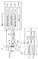
図1は本発明の一実施形態に係る血管脈波測定システムの構成を示すブロック図である。図1において、血管脈波測定システム10の構成要素ではないが、血圧等を測定する対象の被測定者6と、実際に血圧を測定する血管8が図1に示されている。なお、以下の図において、被測定者6の皮膚については図示を省略する。本実施形態に係る血管脈波測定システム10は、従来用いられているコロトコフ音を測定する圧迫カフ法、あるいは、動脈内に、圧力センサが連結されたカテーテルを挿入侵襲させて血管内の圧力を直接測定する観血法に代えて、発光素子と受光素子とを有する光探触子12を用いて血管8の脈動波形を収得して脈波測定を行うシステムである。
FIG. 1 is a block diagram showing a configuration of a vascular pulse wave measurement system according to an embodiment of the present invention. In FIG. 1, although not a component of the vascular pulse
血管脈波測定システム10は、
(a)被測定者6の血管8の脈動取得に適した部位に取り付けられる光探触子12を含み、光探触子12を構成する発光素子を駆動して光を放射させ、皮膚を介して血管により反射される反射光を受光素子によって検出するための光探触子回路20(又は20A,20B)と、
(b)光探触子回路20(又は26)からの出力電圧Voutを増幅する増幅器30と、
(c)増幅器30からの出力電圧をディジタルデータにA/D変換するA/D変換器31と、
(d)内部メモリ50mを含む例えばディジタル計算機などの制御装置であって、血管脈波測定処理モジュール51と、血圧値校正処理モジュール52と、睡眠状態判別処理モジュール53とを備え、A/D変換器31からのディジタルデータを処理して血管脈波データを発生し、血管脈波データに対して血圧値校正処理(図19)、血管脈波測定処理(図20)及び睡眠状態判別処理(図21)を実行する装置コントローラ50と、
(e)例えばディスプレイ又はプリンタであって、装置コントローラ50からの出力データに基づいて、脈動波形表示(移動平均処理後の脈動波形表示61及びローパスフィルタ処理後の脈動波形表示62)及び各血管脈波測定値表示(脈拍、最大血圧値Pmax及び最小血圧値Pmin)を表示する表示部60と、
を備えて構成される。The vascular pulse
(A) It includes an
(B) an
(C) an A /
(D) A control device such as a digital computer including an
(E) A display or printer, for example, based on output data from the device controller 50, pulsation waveform display (
It is configured with.
なお、圧力シートセンサ35及び圧力アクチュエータ36を含む光探触子回路10A(図7A及び図9A)からの出力電圧Voutは増幅器30に出力され、当該圧力シートセンサの圧力値データは装置コントローラ50に出力され、圧力アクチュエータ36への制御信号は装置コントローラ50から出力される。また、圧力シートセンサ36のみの場合は(図7B)、装置コントローラ50と接続される。
The output voltage Vout from the optical probe circuit 10A (FIGS. 7A and 9A) including the
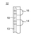
図2は図1の反射型光探触子12の構成を示す側面図である。光探触子12は、所定の保持部13に発光素子14と受光素子16とが回路基板18に取り付けられて配置されて構成される。保持部13は、回路基板18を内蔵し、発光素子14の光放射部と、受光素子16の光検出部とを表面に突き出して配置する部材で、例えば適当なプラスチック材料を成形してなる。発光素子14としては、発光ダイオード(Light Emission Diode: LED)を用いることができ、例えば赤外LEDが用いられる。また、受光素子16としては、フォトダイオード又はフォトトランジスタを用いられる。
FIG. 2 is a side view showing the configuration of the reflective
発光素子14と受光素子16とは、近接して配置されることが好ましいが、発光素子14からの光が受光素子16に直接入らないように、間に遮光璧を設ける等の構造的工夫をすることが好ましい。あるいは、レンズを発光素子14と受光素子16に設け、指向性を高めることもよい。図2の例では、発光素子14と受光素子16が1つずつ設けられているが、複数の発光素子14、複数の受光素子16を設けるものとしてもよい。また、受光素子16の周りを複数の発光素子14で囲むように配置してもよい。光探触子12には、図示されていない適当なバンド、テープ等で被測定者6の血管8の脈拍の検出に適した部位に取り付けられる。図1では、光探触子12が手首の橈骨動脈部7に取り付けられる様子が示されているが、これ以外に、腕の肘部の内側に対応する上腕動脈部、指先、心臓の近傍等の部位に光探触子12を取り付けてもよい。
The
図3は図1の光探触子回路20の構成を示す回路図である。光探触子回路20は、発光素子14に対する駆動回路と、受光素子16に対する検出回路とにより構成され、検出回路からの出力信号を直接に駆動回路に入力させることで同期帰還させて自励発振回路を構成する。
FIG. 3 is a circuit diagram showing a configuration of the
発光素子14に対する駆動回路としては、電源電圧Vccと接地の間に発光素子14と駆動トランジスタ24とを直列に接続して駆動トランジスタ24の制御端子であるベースを所定のバイアス条件とする構成が用いられる。この構成において、駆動トランジスタ24のベースヘの入力信号がハイとなると、駆動トランジスタ24がオンして、発光素子14に駆動電流が流れる。これによって発光素子14が発光し、その光が皮膚を介して血管8に向けて放射される。また、受光素子16のための検出回路としては、正の電源電圧Vccと負の電源電圧−Vccとの間に負荷抵抗22とトランジスタ23と受光素子16とが直列に接続される構成が用いられる。この構成において、発光素子14の光によって照射された血管8からの反射光を皮膚を介して受光素子14が受光することで、受光素子16に光電流が発生する。その光電流の大きさは、負荷抵抗22に流れる電流の大きさに対応する出力電圧Voutの信号(出力電圧信号)として出力される。なお、出力電圧Voutの信号は自励発振信号であるので交流信号である。
As a driving circuit for the
図1に示すように、上記自励発振回路を構成する光探触子回路20からの出力電圧信号は増幅器30及びA/D変換器31を介して装置コントローラ50に出力される。このように、発光素子14から光が血管8(正確には、例えば酸化ヘモグロンビンを含む血液が充填された血管の血管壁)により放射され、血管8からの反射光を受光素子16が受け取る場合には、発光素子14から受光素子16に直接入射する光の影響がないものとして、光探触子回路20からの出力電圧信号は光の伝搬距離(発光素子14から放射された光が受光素子16に到達するまでの距離をいう。)に応じて出力電圧Voutが変化するので、血管8が脈動により変化すると、出力電圧Voutが変化し、すなわち、出力電圧Voutは脈動の変化に対応して変化する。
As shown in FIG. 1, the output voltage signal from the
特許文献1〜3などの従来技術では、大きな出力電圧の変化を得ることができなかったために、その周波数変化を電圧変化に変換して、脈動の変化を検出していたが、本実施形態では、図3に示すように、光探触子回路20内の検出回路の出力信号を直接に駆動回路の入力信号として同期帰還させて自励発振させて自励発振信号を発生させ、かつ詳細後述するように、センサコントローラ25により出力電圧Vout(交流信号である自励発振信号の振幅幅(変化量))が実質的に最大となるように制御して設定することで、脈動波形をきわめて簡単に得ることができる。
In the prior arts such as
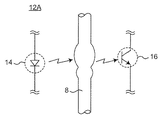
図4は変形例に係る透過型光探触子12Aの構成を示す概略図である。図3の反射型光探触子12に代えて、図4の透過型光探触子12Aを用いてもよい。図3の反射型光探触子12における光の伝搬距離に比較して、透過光の伝搬距離は長くなるが、同様に用いて血管脈波測定を行うことができる。
FIG. 4 is a schematic diagram showing a configuration of a transmission
図5Aは図1の光探触子回路20及び増幅器30の具体例を示す回路図である。図5Aにおいて、光探触子20は、発光素子14とそれの駆動回路と、受光素子16とその検出回路と、駆動回路及び検出回路の動作点を制御するセンサコントローラ25とを備えて構成される。
FIG. 5A is a circuit diagram showing a specific example of the
センサコントローラ25は例えばディジタル計算機などの制御装置であって、距離選択スイッチ26を備える。距離選択スイッチ26は、駆動回路及び検出回路の動作点を決定する初期値(具体的には、抵抗R1,R4の初期値)を設定するためのスイッチであり、例えば「距離大」「距離小」を選択できるように構成される。これは、図10乃至図13を参照して詳細後述するように、それらに図示の電気特性において出力電圧の極値を有する所定の境界伝搬距離を境にしてその前後の領域で、伝搬距離の変化に対する出力電圧の変化(自励発振信号の振幅)として大きな値を得ることができ、脈波電圧を得ることができるからで、測定可能な伝搬距離を拡大することができる。すなわち、「距離大」は境界伝搬距離よりも長い伝搬距離で血管脈波測定を行う場合であり、「距離小」は境界伝搬距離よりも短い伝搬距離で血管脈波測定を行う場合である。
The
センサコントローラ25は、図18の受発光センサ制御処理に従って、抵抗R1,R4を所定の初期値を設定した後、抵抗R1,R4の各抵抗値を変化させて光探触子回路20の出力電圧Voutが実質的に最大となるように制御する。また、光探触子回路20におけるキャパシタC4は直流阻止用に設けられ、かつ検出回路及び駆動回路により構成される同期帰還を含む自励発振回路における自励発振信号の周波数特性を決定するために設けられ、例えば最大心拍周波数を240回/分とすれば、カットオフ周波数が4Hzであるローパスフィルタを挿入するように構成される。さらに、増幅器30は例えばオペアンプ32を備えて公知のごとく構成される。
The
以上の光探触子回路20においては、受光素子16の検出回路からの出力電圧Voutを発光素子14の駆動回路への駆動信号として用いているが、本発明はこれに限らず、出力電流などの電気信号を発光素子14の駆動回路への駆動信号として用いてもよい。
In the
図5Bは図5Aの光探触子回路20の変形例を示す回路図である。図5の光探触子回路20においては、発光素子14と受光素子16との組は1対しか図示していないが、好ましくは、境界伝搬距離(受光素子16の出力コレクタ電流が実質的に最大となる伝搬距離)が互いに異なる2対以上備えて素子選択スイッチ27を用いて切り換えるように構成される。これは、図10乃至図13を参照して詳細後述するように、上記境界伝搬距離付近では、伝搬距離の変化に対する出力電圧の変化が小さくなり、自励発振信号である脈波電圧として実質的に得ることができないためで、互いに異なる境界伝搬距離を有する2対以上の受発光センサを備えることで、測定不可能な伝搬距離を解消することができるためである。図5Bでは、発光素子14と受光素子16の第1の光探触子12と、発光素子14aと受光素子16aの第2の光探触子12aとの2対の受発光センサ対を備えるとともに、センサコントローラ25はさらに素子選択スイッチ27を備える。素子選択スイッチ27により例えば「素子1」「素子2」を選択できるように構成され、「素子1」を選択したとき、センサコントローラ25はスイッチ41,42を連動して接点a側に切り換えて、発光素子14と受光素子16の第1の光探触子12を選択して動作させ、「素子2」を選択したとき、センサコントローラ25はスイッチ41,42を連動して接点b側に切り換えて、発光素子14aと受光素子16aの第2の光探触子12aを選択して動作させる。
FIG. 5B is a circuit diagram showing a modification of the
図6は、図1の光探触子回路20の受発光センサの取り付け例を示す正面図であって、図6(a)は被測定者の手首の橈骨動脈部7に光探触子回路20の受発光センサを取り付けた一例を示す正面図であり、図6(b)は被測定者の指先9に光探触子回路20の受発光センサを取り付けた一例を示す正面図である。
FIG. 6 is a front view showing an example of attachment of the light emitting / receiving sensor of the
図7Aは第1の変形例に係る、圧力シートセンサ及び受発光センサを含む光探触子回路20Aの取り付け例を示す正面図であって、図7Bは第2の変形例であって、被測定者の指先9に光探触子回路20の受発光センサを取り付けかつ圧力シートセンサ35を手首の橈骨動脈部7に取り付けた場合の一例を示す正面図である。すなわち、図7Aに示すように、圧力シートセンサを受発光センサともに光探触子回路20Aに内蔵してもよいし、図7Bに示すように、圧力シートセンサと、受発光センサとを別々に設けてもよい。ここで、各圧力シートセンサは、図20の血管脈波測定処理に先立って実行される図19の血圧値校正処理において、電圧値と血圧値とを対応づける変換式(又は変換テーブル)を生成するために用いられる。
FIG. 7A is a front view showing an attachment example of an
図8Aは図1の血管脈波測定システムにより測定された脈波電圧値(例えば、増幅器30の出力電圧値)の最大電圧値Vmax及び最小電圧値Vminを示すグラフである。図8Aから明らかなように、脈波電圧値は、脈動の変化に応じて周期的に変化し、最大電圧値Vmaxと最小電圧値Vminをとり、互いに隣接する2つの最小電圧値Vmin間の時間期間を時間期間Tintと定義する。 FIG. 8A is a graph showing the maximum voltage value Vmax and the minimum voltage value Vmin of the pulse wave voltage value (for example, the output voltage value of the amplifier 30) measured by the vascular pulse wave measurement system of FIG. As is clear from FIG. 8A, the pulse wave voltage value periodically changes according to the change in pulsation, takes the maximum voltage value Vmax and the minimum voltage value Vmin, and the time between two adjacent minimum voltage values Vmin. The period is defined as a time period Tint.
図8Bは図1の血管脈波測定システムにより測定された脈波電圧値に対応する血圧値の最大血圧値Pmax及び最小血圧値Pminを示すグラフである。図8Bから明らかなように、血圧値は、脈動の変化に応じて図8Aの脈波電圧値と同様に周期的に変化し、最大血圧値Pmaxと最小血圧値Pminをとる。図8Aと図8Bとの間の変換は、図8Cを参照して説明するように、図19の血圧値校正処理で生成される変換式(変換テーブルであってもよい)で行うことができる。 FIG. 8B is a graph showing the maximum blood pressure value Pmax and the minimum blood pressure value Pmin of the blood pressure values corresponding to the pulse wave voltage values measured by the vascular pulse wave measurement system of FIG. As is clear from FIG. 8B, the blood pressure value periodically changes in the same manner as the pulse wave voltage value of FIG. 8A according to the change in pulsation, and takes the maximum blood pressure value Pmax and the minimum blood pressure value Pmin. The conversion between FIG. 8A and FIG. 8B can be performed with a conversion formula (which may be a conversion table) generated by the blood pressure value calibration processing of FIG. 19 as described with reference to FIG. 8C. .
図8Cは図1の血管脈波測定システムにより測定された脈波電圧値から血圧値への変換を示すグラフである。公知の通り、被測定者が異なれば、脈波電圧値と血圧値との間の相関関係が異なるので、予め被測定者ごとに相関関係を求めておく必要がある。また、同じ被測定者であっても、安静状態と運動状態等で、脈波電圧値と血圧値との間の相関関係が異なることがあるので、予め測定状態を設定してそれぞれ相関関係を求めておく必要がある。図1の血管脈波測定システムで得られる脈波電圧値と血圧値との間の相関関係は、被測定者ごとに、測定条件ごとに関連付けられて変換式(又は変換テーブル)の形式で装置コントローラ50の内部メモリ50mに格納される。図8Cは、被測定者より変換式Q1,Q2で異なることを示すものである。このようにして、脈波電圧値から血圧値への変換を行うと、これに基づいて、脈拍数、最大血圧Pmax、最小血圧Pmin等の血管脈波測定を行うことができる。
FIG. 8C is a graph showing the conversion from the pulse wave voltage value measured by the blood vessel pulse wave measurement system of FIG. 1 into a blood pressure value. As is well known, since the correlation between the pulse wave voltage value and the blood pressure value is different for each person to be measured, it is necessary to obtain the correlation for each person to be measured in advance. Even if the subject is the same, the correlation between the pulse wave voltage value and the blood pressure value may be different between the resting state and the exercise state. It is necessary to ask for it. The correlation between the pulse wave voltage value and the blood pressure value obtained by the vascular pulse wave measurement system in FIG. 1 is associated with each measurement condition for each measurement condition and is converted into a conversion formula (or conversion table). It is stored in the
図9Aは図7Aに図示された第1の変形例に係る、圧力シートセンサ及び受発光センサを含む光探触子回路20Aの構成を示す縦断面図である。図9Aにおいて、光探触子回路20Aは、発光素子及び受光素子を含む光探触子回路20と、被測定者の血管8に対する圧力を検出する圧力シートセンサ35と、被測定者の血管8に対して圧力を印加する圧力アクチュエータ36とが所定の筐体37内で例えばウレタンなどの充填材38を用いて設けられる。ここで、好ましくは、光探触子回路20と圧力シートセンサ35とは直接に接触しかつ圧力シートセンサ35と圧力アクチュエータ36とは直接に接触して設けられる。これにより、圧力アクチュエータ36の応力が図の下側方向36aで、圧力シートセンサ35の上部中央の押圧部35aに対して、圧力シートセンサ35を介して光探触子回路20に印加され、さらに、その応力が光探触子回路20から被測定者の皮膚を介して血管8に印加される。この光探触子回路20Aは例えば図19の血圧値校正処理で用いられる。
FIG. 9A is a longitudinal sectional view showing a configuration of an
図9Bは図9Aの変形例であって、被験者などの人間の指先で押圧する光探触子回路20Bの構成を示す縦断面図である。図9Aの光探触子回路20Aの圧力アクチュエータ36に代えて、被験者などの人間の指先8により図の下側方向9aで筐体37の上部中央部37aから圧力シートセンサ35の上部中央の押圧部35aに対して応力を加えるものである。この光探触子回路20Bは例えば図19の血圧値校正処理の変形例で用いられる。
FIG. 9B is a modification of FIG. 9A and is a longitudinal sectional view showing a configuration of an
次いで、図5のセンサコントローラ25による受発光センサ制御処理(図18)を実行するための意義を発見した実験結果について以下に説明する。以下の実験で使用した受発光センサは、ローム社製RPR−220型反射型フォトセンサ(フォトリフレクタ)であって、出力トランジスタのコレクタ電流が実質的に最大となる境界伝搬距離は6乃至7mmである。なお、図面において示していないが、各種の受発光センサはそれぞれ境界伝搬距離を用途ごとに有しており、本実施形態では、上述のように、血管脈波測定時の不可能な伝搬距離を無くするために複数対の受発光センサを備えることが好ましい。
Next, an experimental result in which the significance for executing the light emitting / receiving sensor control process (FIG. 18) by the
図10は図5の光探触子回路20において、電源電圧Vcc=15Vで抵抗R1=18kΩのときであって、抵抗R4を変化したときの光の伝搬距離に対する出力電圧を示すグラフである。図10から明らかなように、伝搬距離が6mm付近では、出力電圧曲線の傾斜が小さくなっており、伝搬距離に対する変化は小さいので、血管壁が変動しても出力電圧の変化は小さいといえる。特に、抵抗R4=200Ωでは、出力電圧の傾斜はほとんど0であり、脈波信号の変化を得ることができないと考えられる。これが、上述した血管脈波測定の不可能な伝搬距離である。この問題点を解消するためには、境界伝搬距離が異なる受発光センサを用いて当該血管脈波測定の不可能な伝搬距離を解消できる。
FIG. 10 is a graph showing the output voltage with respect to the light propagation distance when the power supply voltage Vcc = 15 V and the resistance R1 = 18 kΩ in the
光探触子12の取り付け位置を指先である場合、0mm〜2mm程度となり、境界伝搬距離(6mm)の左側の出力電圧曲線の領域で動作させれば、脈波信号の変化を得ることができると考えられる。一方、光探触子12の取り付け位置を手首の橈骨動脈部である場合、1mm〜3mm程度となり、当該出力電圧曲線の極小値に対応する境界伝搬距離(6mm)の右側の出力電圧曲線の領域で動作させれば、脈波信号の変化を得ることができると考えられる。従って、前者を「距離小」の動作点の初期値として設定し、後者を「距離大」の動作点の初期値として設定できる。また、抵抗R4を変化させることで、出力電圧曲線の傾斜を大きくすることができ、より大きな脈波信号の変化を得ることができると考えられる。
When the attachment position of the
図10の具体例を参照して動作点の初期値の設定について以下に説明する。抵抗R4=250Ωとしたとき、「距離小」領域の伝搬距離=4mmにおける動作点P1で動作させれば、所定のしきい値以上の傾斜角度θ1を得ることができ、これを動作点の初期値として設定した後、センサコントローラ25は、抵抗R1,R4の抵抗値を変化させて実質的に最大の出力電圧値Voutを得ることができるように制御することで、より大きな脈波信号を得ることができる。また、抵抗R4=250Ωとしたとき、「距離大」領域の伝搬距離=10mmにおける動作点P2で動作させれば、所定のしきい値以上の傾斜角度θ2を得ることができ、これを動作点の初期値として設定した後、センサコントローラ25は、抵抗R1,R4の抵抗値を変化させて実質的に最大の出力電圧値Vout(自励発振信号)を得ることができるように制御することで、より大きな脈波信号を得ることができる。
The setting of the initial value of the operating point will be described below with reference to the specific example of FIG. When the resistance R4 = 250Ω, if the operation is performed at the operating point P1 at the propagation distance = 4 mm in the “small distance” region, an inclination angle θ1 greater than a predetermined threshold value can be obtained. After setting as a value, the
なお、本実施形態において、駆動回路の動作点は例えば抵抗R4の抵抗値で決定され、検出回路の動作点は例えば抵抗R1の抵抗値で決定され、これら駆動回路の動作点及び駆動回路の動作点の決定により、図10の電気特性の動作点(例えばP1,P2)を決定できる。 In this embodiment, the operating point of the driving circuit is determined by, for example, the resistance value of the resistor R4, and the operating point of the detection circuit is determined by, for example, the resistance value of the resistor R1, and the operating point of these driving circuits and the operation of the driving circuit are determined. By determining the points, the operating points (for example, P1 and P2) of the electrical characteristics of FIG. 10 can be determined.
図11は、図5の光探触子回路20において、電源電圧Vcc=15Vで抵抗R4=200Ωのときであって、抵抗R1を変化したときの光の伝搬距離に対する出力電圧を示すグラフである。図11の出力電圧曲線も図10と同様の出力電圧曲線が得られており、「距離大」「距離小」の動作点の初期値の設定、並びに抵抗R1の変化による出力電圧曲線の傾斜の制御及びその最大化の設定を行うことができる。
FIG. 11 is a graph showing the output voltage with respect to the light propagation distance when the resistance R1 is changed in the
図12は図5の光探触子回路20において、電源電圧Vcc=5Vで抵抗R4=200Ωのときであって、抵抗R1を変化したときの光の伝搬距離に対する出力電圧を示すグラフである。図12の出力電圧曲線も、抵抗R1=15kΩ及び20kΩのときのより長い距離範囲での飽和状態を除いて、図11と同様の出力電圧曲線が得られており、「距離大」「距離小」の動作点の初期値の設定、並びに抵抗R1の変化による出力電圧曲線の傾斜の制御及びその最大化の設定を行うことができる。
FIG. 12 is a graph showing the output voltage with respect to the light propagation distance when the power supply voltage Vcc = 5V and the resistance R4 = 200Ω in the
図13は、図5の光探触子回路20において、電源電圧Vcc=30Vで抵抗R4=200Ωのときであって、抵抗R1を変化したときの光の伝搬距離に対する出力電圧を示すグラフである。図13の出力電圧曲線も、抵抗R1=40kΩのときのより長い距離範囲での傾斜ゼロの状態を除いて、図11と同様の出力電圧曲線が得られており、「距離大」「距離小」の動作点の初期値の設定、並びに抵抗R1の変化による出力電圧曲線の傾斜の制御及びその最大化の設定を行うことができる。
FIG. 13 is a graph showing the output voltage with respect to the light propagation distance when the power supply voltage Vcc = 30 V and the resistance R4 = 200Ω in the
なお、グラフを図示しないが、光探触子12の発光素子及び受光素子を別の素子対に取り替えた場合、境界伝搬距離を異ならせることができ、これにより、上記いわゆる「距離大」「距離小」の距離範囲を異ならせることができる。すなわち、距離範囲の選択設定を素子選択スイッチ27により選択できる。
Although the graph is not shown, when the light emitting element and the light receiving element of the
以上説明したように、センサコントローラ25は、距離選択スイッチ26を備え、さらに好ましくは素子選択スイッチ27を備え、距離選択スイッチ26により、駆動回路及び検出回路を含む光探触回路20の動作点を決定する初期値(具体的には、抵抗R1,R4の初期値)を設定するために、例えば「距離大」「距離小」を選択でき、素子選択スイッチ27により例えば「素子1」「素子2」を選択できる。センサコントローラ25は、図18の受発光センサ制御処理に従って、抵抗R1,R4を所定の初期値(予め測定された伝搬距離に対する出力電圧特性に基づいて決定される最適な動作点に対応する値をいう。)を設定した後、抵抗R1,R4の各抵抗値を変化させて光探触子回路20の出力電圧Voutが実質的に最大となるように制御する。
As described above, the
図14は、図1の血管脈波測定システムにより測定された脈動波形を血圧波形に変換して示すグラフである。図14から明らかなように、出力電圧波形を血圧波形に変換することで図14の脈波波形の表示を得ることができる。 FIG. 14 is a graph showing the pulsation waveform measured by the vascular pulse wave measurement system of FIG. 1 converted into a blood pressure waveform. As is clear from FIG. 14, the display of the pulse wave waveform of FIG. 14 can be obtained by converting the output voltage waveform into a blood pressure waveform.
図15は図1の血管脈波測定システムにおいて、移動平均法を用いて脈動波形を処理する動作を示すグラフである。図15において、血管脈波測定システムにより得られた脈波電圧の生データから移動平均法を用いて滑らかな脈動波形を生成する様子を示す図である。図15(a)は、横軸が時間で、縦軸は脈波電圧であり、各サンプリングタイムにおける脈波電圧の変化の様子が示されている。図15(b)は、横軸が時間で、その原点位置等は図15(a)と揃えてある。縦軸は、図15(a)の各サンプリングタイムにおけるデータの移動平均値bである。移動平均値は、例えば5つのデータについて行うものとした。この場合、サンプリングタイムiのとぎの脈波電圧の生データをaiとすると、サンプリングタイムiのときの移動平均値biは次式を用いて計算できる。FIG. 15 is a graph showing an operation of processing the pulsation waveform using the moving average method in the vascular pulse wave measurement system of FIG. In FIG. 15, it is a figure which shows a mode that a smooth pulsation waveform is produced | generated using the moving average method from the raw data of the pulse wave voltage obtained by the vascular pulse wave measurement system. In FIG. 15A, the horizontal axis represents time and the vertical axis represents pulse wave voltage, and the state of change of the pulse wave voltage at each sampling time is shown. In FIG. 15B, the horizontal axis is time, and the origin position and the like are aligned with FIG. The vertical axis represents the moving average value b of the data at each sampling time in FIG. For example, the moving average value is set for five data. In this case, the raw data of the pulse wave voltage sharpener sampling time i and a i, the moving average value b i when the sampling time i can be calculated using the following equation.
[数1]
b=(ai−4+ai−3+ai−2+ai−1+ai)/5[Equation 1]
b = (a i−4 + a i−3 + a i−2 + a i−1 + a i ) / 5
すなわち、サンブリングデータaiが取得されると直ちに移動平均値biが算出できるのでリアルタイム処理が可能である。なお、移動平均に用いるデータ数は5でなくてもよい。That is, since the moving average value b i can be calculated as soon as the sampling data a i is acquired, real-time processing is possible. Note that the number of data used for the moving average need not be five.
図16(a)は図1の血管脈波測定システムにより測定されたある被測定者の覚醒時の各種信号波形の一例を示すグラフであり、図16(b)は図1の血管脈波測定システムにより測定されたある被測定者の無呼吸時の各種信号波形の一例を示すグラフである。 16A is a graph showing an example of various signal waveforms at the time of awakening of a measurement subject measured by the vascular pulse wave measurement system of FIG. 1, and FIG. 16B is a vascular pulse wave measurement of FIG. It is a graph which shows an example of the various signal waveforms at the time of apnea of a certain subject measured by the system.
図16(a)において、覚醒時の各測定波形は以下の通りである。
(a)R−EOG A1:公知の眼球電計により測定された眼球電波形である。
(b)Chin−Ref:公知の顎運動測定器により測定された顎の変位量である。
(c)心電図:公知の心電計により測定された心電波形である。
(d)筋電図:公知の筋電計により測定された筋電波形である。
(e)いびき:小型マイクロホンにより測定されたいびき音である。
(f)呼吸波形:被測定者の呼吸にともなう身体下の圧力変化を感圧センサが検出し、呼吸波形を計測したときの呼吸波形である。
(g)SpO2:公知のパルスオキシメーターにより測定された血中酸素飽和度である。
(h)本システム:本実施形態に係る血管脈波測定システムにより測定された脈波波形である。In FIG. 16A, each measurement waveform at the time of awakening is as follows.
(A) R-EOG A1: An electrooculogram measured by a known electrooculometer.
(B) Chin-Ref: The amount of jaw displacement measured by a known jaw movement measuring device.
(C) Electrocardiogram: An electrocardiogram waveform measured by a known electrocardiograph.
(D) Electromyogram: EMG waveform measured by a known electromyograph.
(E) Snoring: A snoring sound measured by a small microphone.
(F) Respiration waveform: a respiration waveform when the pressure sensor detects a change in pressure under the body accompanying the respiration of the measurement subject and measures the respiration waveform.
(G) SpO2: blood oxygen saturation measured by a known pulse oximeter.
(H) This system: a pulse wave waveform measured by the blood vessel pulse wave measurement system according to this embodiment.
図16(b)において、無呼吸時の各測定波形は以下の通りである。
(a)R−EOG A1:公知の眼球電計により測定された眼球電波形である。
(b)Chin−Ref:公知の顎運動測定器により測定された顎の変位量である。
(c)心電図:公知の心電計により測定された心電波形である。
(d)筋電図:公知の筋電計により測定された筋電波形である。
(e)いびき:小型マイクロホンにより測定されたいびき音である。
(f)呼吸温度センサ:口元に設けられた温度センサにより測定された呼吸温度である。
(g)呼吸圧:被測定者の呼吸にともなう身体下の圧力変化を感圧センサが検出し、呼吸波形を計測したときの呼吸圧波形である。
(h)胸郭変動:被測定者の胸郭の変化を測定する応力センサにより測定された胸郭変動量である。
(i)腹部変動:被測定者の腹部の変化を測定する応力センサにより測定された腹部変動量である。
(j)SpO2:公知のパルスオキシメーターにより測定された血中酸素飽和度である。
(k)本システム:本実施形態に係る血管脈波測定システムにより測定された脈波波形である。In FIG.16 (b), each measurement waveform at the time of apnea is as follows.
(A) R-EOG A1: An electrooculogram measured by a known electrooculometer.
(B) Chin-Ref: The amount of jaw displacement measured by a known jaw movement measuring device.
(C) Electrocardiogram: An electrocardiogram waveform measured by a known electrocardiograph.
(D) Electromyogram: EMG waveform measured by a known electromyograph.
(E) Snoring: A snoring sound measured by a small microphone.
(F) Respiration temperature sensor: Respiration temperature measured by a temperature sensor provided at the mouth.
(G) Respiratory pressure: This is a respiratory pressure waveform when the pressure sensor detects a change in pressure under the body accompanying the breathing of the measurement subject and measures the respiratory waveform.
(H) Thoracic variation: Thoracic variation measured by a stress sensor that measures changes in the subject's thorax.
(I) Abdominal variation: An abdominal variation measured by a stress sensor that measures a change in the abdomen of the measurement subject.
(J) SpO2: blood oxygen saturation measured by a known pulse oximeter.
(K) This system: a pulse wave waveform measured by the blood vessel pulse wave measurement system according to this embodiment.
本実施形態に係る血管脈波測定システムにより測定された図16のデータには、いままでの測定装置ではわからなかった多くの情報が含まれている。図16(a)においては、正常レム睡眠中であるが、当該記録120秒間に2回の覚醒反応があり、その2回とも覚醒反応開始とともに脈圧はやや上昇しその後、急激な低下を示している。覚醒反応による交感神経活動上昇と抹消の血管抵抗の一時的上昇、その後反射的な血管拡張による脈圧低下が観察され、正常睡眠において脈圧の変化が、脳波上の覚醒反応と同期していると考えられる。これは脳波を測定しない小型の血管脈波測定システムで睡眠評価が可能となると考えられる。 The data in FIG. 16 measured by the vascular pulse wave measurement system according to the present embodiment includes a lot of information that has not been understood by conventional measurement apparatuses. In FIG. 16 (a), while normal REM sleep is in progress, there are two wakefulness responses in the recorded 120 seconds, and the pulse pressure rises a little at the start of the wakefulness response, and then shows a sharp drop. ing. Increased sympathetic nerve activity due to arousal response, temporary increase in peripheral vascular resistance, and subsequent decrease in pulse pressure due to reflex vasodilation were observed, and changes in pulse pressure in normal sleep are synchronized with arousal response on EEG it is conceivable that. This is considered to enable sleep evaluation with a small vascular pulse wave measurement system that does not measure brain waves.
図16(b)では、典型的な無呼吸、努力性呼吸〜覚醒反応、過呼吸という一連の中で、無呼吸中の努力性呼吸に同期する小さな周期の変動がみられながら(変動が小さいため実測定数から周波数解析をする必要があると考えられる)無呼吸終了まで、脈圧が徐々に上昇していくことがわかる。その後、覚醒反応、呼吸再開〜過呼吸とともに脈圧は急激に降下する。おそらくこの患者の昼の安静時の血圧はこの降下した後、安定したレベルであり、無呼吸中の血圧上昇は、無呼吸による交感神経活動の過剰上昇によるもので、過去に本発明者らが調べた中では、ピークが収縮期血圧228という患者もいた。従って、無呼吸症候群の患者の場合は合併頻度が問題となる、循環器系疾患の発症に関わる、睡眠中の特殊な循環動態を評価できると考えられる。 In FIG. 16B, in a series of typical apnea, forced breathing-wakefulness reaction, and hyperpnea, a small cycle fluctuation synchronized with the forced breathing during apnea is observed (the fluctuation is small). Therefore, it can be seen that the pulse pressure gradually increases until the end of apnea. Thereafter, the pulse pressure drops rapidly with awakening reaction, resumption of breathing and hyperventilation. Perhaps the patient's daytime resting blood pressure is at a stable level after this drop, and the increase in blood pressure during apnea is due to excessive increase in sympathetic nerve activity due to apnea. Among the patients examined, some patients had peak systolic blood pressure 228. Therefore, in the case of patients with apnea syndrome, it is considered that special circulatory dynamics during sleep related to the onset of circulatory system diseases in which complication frequency is a problem can be evaluated.
図16(a)及び図16(b)の脈波波形のグラフから、レム覚醒時は、最大血圧値Pmaxが無呼吸時に比較して緩やかに上昇した後、下降し、それを繰り返していることがわかる。また、無呼吸時は、最大血圧値Pmaxがレム覚醒時に比較して早く上昇した後、下降し、それを繰り返していることがわかる。 From the pulse wave graphs of FIGS. 16 (a) and 16 (b), when REM awakens, the maximum blood pressure value Pmax gradually rises compared to apnea, then falls and repeats. I understand. It can also be seen that during apnea, the maximum blood pressure value Pmax rises earlier than when REM awakens, then falls and repeats.
図17(a)は覚醒時の最大血圧値Pmaxの変化をモデル化して示す図であり、図17(b)は無呼吸時の最大血圧値Pmaxの変化をモデル化して示す図である。図17(a)及び図17(b)の最大血圧値Pmaxのモデル図から明らかなように、レム覚醒時の最大血圧値Pamxの変化周期Tarは無呼吸時のそれに比較して長く、原点Sから見た、レム覚醒時の最大血圧値Pmaxの上昇傾斜角度αarは無呼吸時のそれに比較して小さいことがわかる。これらの知見及び治験に基づいて、図21の睡眠異常判別処理のフローチャートを作成した。 FIG. 17A is a diagram showing a change in the maximum blood pressure value Pmax at the time of awakening, and FIG. 17B is a diagram showing a change in the maximum blood pressure value Pmax at the time of apnea. As is apparent from the model diagrams of the maximum blood pressure value Pmax in FIGS. 17A and 17B, the change period Tar of the maximum blood pressure value Pamx at the time of REM awakening is longer than that at the time of apnea, and the origin S It can be seen that the rising inclination angle αar of the maximum blood pressure value Pmax at the time of REM awakening is smaller than that at the time of apnea. Based on these findings and clinical trials, the flowchart of the sleep abnormality determination process of FIG. 21 was created.
図18は図5のセンサコントローラ25により実行される受発光センサ制御処理を示すフローチャートである。当該受発光センサ制御処理では、図5の実施形態を含む変形例に係る図5Bの場合について説明する。
FIG. 18 is a flowchart showing a light emitting / receiving sensor control process executed by the
図18において、まず、ステップS1で選択スイッチ26,27の設定値は「距離大」「素子1」であるか否かが判断され、YESのときはステップS4に進む一方、NOのときはステップS2に進む。次いで、ステップS2で選択スイッチ26,27の設定値は「距離小」「素子1」であるか否かが判断され、YESのときはステップS5に進む一方、NOのときはステップS3に進む。さらに、ステップS3で選択スイッチ26,27の設定値は「距離大」「素子2」であるか否かが判断され、YESのときはステップS6に進む一方、NOのときはステップS7に進む。
In FIG. 18, first, in step S1, it is determined whether or not the set values of the selection switches 26 and 27 are “large distance” and “
ステップS4では、「距離大」「素子1」であるときの最適な動作点の初期値である抵抗R1,R4の抵抗値R1int1,R4int1をそれぞれ抵抗R1,R4の抵抗値として設定してステップS8に進む。ステップS5では、「距離小」「素子1」であるときの最適な動作点の初期値である抵抗R1,R4の抵抗値R1int2,R4int2をそれぞれ抵抗R1,R4の抵抗値として設定してステップS8に進む。ステップS6では、「距離大」「素子2」であるときの最適な動作点の初期値である抵抗R1,R4の抵抗値R1int3,R4int3をそれぞれ抵抗R1,R4の抵抗値として設定してステップS8に進む。ステップS7では、「距離小」「素子2」であるときの最適な動作点の初期値である抵抗R1,R4の抵抗値R1int4,R4int4をそれぞれ抵抗R1,R4の抵抗値として設定してステップS8に進む。さらに、ステップS8では抵抗R1の抵抗値を固定して出力電圧Voutが実質的に最大となるように抵抗R4の抵抗値を変化させ、次いで、ステップS9では、抵抗R4の抵抗値を固定して出力電圧Voutが実質的に最大となるように抵抗R1の抵抗値を変化させて、当該処理を終了する。
In step S4, the resistance values R1int1 and R4int1 of the resistors R1 and R4, which are the initial values of the optimum operating points when “distance is large” and “
なお、上記各動作点の初期値である抵抗R1,R4の抵抗値R1int1〜R1int4,R4int1〜R4int4は予め測定された図10などの電気特性から予め決定されて内部メモリ50mに格納される。
Note that the resistance values R1int1 to R1int4 and R4int1 to R4int4 of the resistors R1 and R4, which are initial values of the respective operating points, are determined in advance from the electrical characteristics shown in FIG. 10 and the like measured in advance and stored in the
以上の図18の処理では、検出回路と駆動回路の両方の動作点をそれぞれ所定の初期値に設定した後、出力電圧Voutが実質的に最大となるように検出回路と駆動回路の両方の動作点を制御しているが、本発明はこれに限らず、検出回路と駆動回路の両方の動作点をそれぞれ所定の初期値に設定した後、出力電圧Voutが実質的に最大となるように検出回路と駆動回路の少なくとも一方の動作点を制御してもよい。 In the processing of FIG. 18, the operation points of both the detection circuit and the drive circuit are set so that the output voltage Vout is substantially maximized after the operating points of both the detection circuit and the drive circuit are set to predetermined initial values. However, the present invention is not limited to this, and after setting the operating points of both the detection circuit and the drive circuit to predetermined initial values, detection is performed so that the output voltage Vout is substantially maximized. You may control the operating point of at least one of a circuit and a drive circuit.
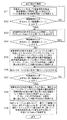
図19は、従来技術に係るカフ圧迫法と同様の原理を用いて、最大血圧値と最小血圧値を校正するための、図1の装置コントローラ50の血圧値校正処理モジュール52により実行される血圧値校正処理を示すフローチャートである。
FIG. 19 shows the blood pressure executed by the blood pressure value
図19において、まず、ステップS11で受発光センサを用いて脈波信号を検出し、脈波信号の時間的に互いに隣接する2つの最小電圧値の時間期間Tint(図8A参照)を演算し、ステップS12において時間期間Tintは所定のしきい値範囲に入っているか否かが判断され(すなわち、脈波信号が検出されているか否かが判断され)、YESのときはステップS13に進む一方、NOのときはステップS11に戻る。ここで、時間期間Tintの所定のしきい値範囲は、脈波信号を検出したか否かの判断範囲であり、上記しきい値範囲は経験値として、例えば0.2秒≦Tint≦2秒である。当該しきい値範囲に時間期間Tintが入っておれば、脈波を検出したと判断する。ステップS13において、被測定者6の脈波を検出したと判断し、圧力アクチュエータ36に所定の差分圧力だけインクリメントする圧力上昇コマンドを出力する。そして、ステップS14において、時間期間Tintは所定のしきい値範囲に入っているか否かが判断され(すなわち、脈波信号が検出されているか否かが判断され)、NOのときはステップS15に進む一方、YESのときはステップS13に戻る。 In FIG. 19, first, in step S11, a pulse wave signal is detected using a light emitting / receiving sensor, and a time period Tint (see FIG. 8A) of two minimum voltage values adjacent to each other in time of the pulse wave signal is calculated. In step S12, it is determined whether or not the time period Tint is within a predetermined threshold range (that is, whether or not a pulse wave signal is detected). If YES, the process proceeds to step S13. If NO, the process returns to step S11. Here, the predetermined threshold range of the time period Tint is a determination range of whether or not a pulse wave signal is detected, and the threshold range is an experience value, for example, 0.2 seconds ≦ Tint ≦ 2 seconds. It is. If the time period Tint is within the threshold range, it is determined that a pulse wave has been detected. In step S13, it is determined that the pulse wave of the person to be measured 6 has been detected, and a pressure increase command for incrementing the pressure actuator 36 by a predetermined differential pressure is output. In step S14, it is determined whether or not the time period Tint is within a predetermined threshold range (that is, whether or not a pulse wave signal is detected). If NO, the process proceeds to step S15. On the other hand, if YES, the process returns to step S13.
ステップS15では、被測定者6の脈波を検出しなくなったと判断し、検出しなくなったサンプリングタイミングよりも1つ前のサンプリングタイミングよりも前の脈波信号の一周期期間内の最大電圧値を最大血圧値電圧として内部メモリ50mに格納するとともに、圧力シートセンサ35の検出圧力値を最大血圧値として内部メモリ50mに格納する。そして、ステップS16において、所定の差分圧力だけデクリメントする圧力アクチュエータ36に圧力下降コマンドを出力する。次いで、ステップS17において、時間期間Tintは所定のしきい値範囲に入っているか否かが判断され(すなわち、脈波信号が検出されているか否かが判断され)、YESのときはステップS18に進む一方、NOのときはステップS16に進む。ステップS18では、被測定者6の脈波を検出したと判断し、検出したサンプリングタイミングからその直後の脈波信号の一周期期間内の最小電圧値を最小血圧値電圧として内部メモリ50mに格納するとともに、圧力シートセンサ35の検出圧力値を最小血圧値として内部メモリ50mに格納する。また、ステップS19において、内部メモリ50mに格納された最大血圧値電圧とそれに対応する最大血圧値及び最小血圧値電圧とそれに対応する最小血圧値に基づいて、図8Cを参照して説明したように、直線近似法を用いて電圧値から血圧値への変換を示す変換式(又は血圧変換テーブル)を生成して内部メモリ50mに格納し、当該処理を終了する。
In step S15, it is determined that the pulse wave of the person to be measured 6 is no longer detected, and the maximum voltage value within one cycle period of the pulse wave signal before the sampling timing immediately before the sampling timing that is no longer detected is determined. The maximum blood pressure value voltage is stored in the
図19の血圧値校正処理を例えば図9Aの光探触子回路20Aを用いて実行しているが、本発明はこれに限らず、図9Bの光探触子回路20Bを用いて実行してもよい。この場合において、ステップS13では、被測定者6の脈波を検出したと判断し、圧力アクチュエータ36を用いず、被験者などの人間に対して指先9で光探触子回路20Bの上部(それを介して圧力シートセンサ35の押圧部)を押圧するように指示するメッセージをLCD表示部(図示せず。)などに表示する。このとき、人間は指先9で押圧する。また、ステップS16では、被測定者6の脈波を検出しなくなったと判断し、圧力アクチュエータ36を用いず、被験者などの人間に対して指先9での上記応力をゆるめて低下させるように指示するメッセージをLCD表示部(図示せず。)などに表示する。このとき、人間は指先9の押圧をゆるめる。このように、圧力アクチュエータ36に代えて、被測定者などの人間の指先9で代用することができる。
The blood pressure value calibration process of FIG. 19 is executed using, for example, the
以上で説明した図9A又は図9Bの光探触子回路20A又は20Bと、図19又はその変形例の血圧値校正処理を用いることにより、当該血管脈波測定システムにおいて、従来技術に比較して極めて簡単な校正でかつ高精度で、血管脈波信号の血圧値電圧を血圧値に変換するように校正することができる。
By using the
図20は図1の装置コントローラ50の血管脈波測定処理モジュール51により実行される血管脈波測定を示すフローチャートである。
FIG. 20 is a flowchart showing blood vessel pulse wave measurement executed by the blood vessel pulse wave
図20において、ステップS21で例えば直近の5周期分の脈波波形データ(A/D変換器31からの電圧値データをいう。)をバッファメモリに格納し、ステップS22において脈波波形データのデータ値は演算範囲以内であるか否かが判断され、YESのときはステップS23に進む一方、NOのときはステップS21に戻る。ステップS23において、上記5周期分の脈波波形データに対して高周波ノイズ除去のためのローパスフィルタ処理を実行し、ステップS24において、ローパスフィルタ処理後の脈動波形データに対して、図15を参照して説明した移動平均法を用いた移動平均処理を実行し、さらに、ステップS25において変換式を用いた電圧値から血圧値への変換による血圧測定処理を実行する。さらに、ステップS26において、変換された血圧値を用いて脈波表示データを作成して脈波(リアルタイム)を表示部60に表示し、脈拍及び最大血圧値及び最小血圧値を演算して表示部60に表示する。ステップS27では、測定終了か否かが判断され、YESのときは当該処理を終了する一方、NOのときはステップS21に戻る。
20, in step S21, for example, pulse waveform data for the latest five cycles (referred to as voltage value data from the A / D converter 31) is stored in the buffer memory, and in step S22, the pulse waveform data is stored. It is determined whether or not the value is within the calculation range. If YES, the process proceeds to step S23. If NO, the process returns to step S21. In step S23, low-pass filter processing for removing high-frequency noise is performed on the pulse waveform data for the above five cycles. In step S24, referring to FIG. 15 for pulsation waveform data after low-pass filter processing. The moving average process using the moving average method described above is executed, and the blood pressure measurement process by converting the voltage value into the blood pressure value using the conversion formula is executed in step S25. Further, in step S26, pulse wave display data is generated using the converted blood pressure value, the pulse wave (real time) is displayed on the
図21は図1の装置コントローラ50の睡眠異常判別処理モジュール53により実行される睡眠異常判別処理を示すフローチャートである。
FIG. 21 is a flowchart showing sleep abnormality determination processing executed by the sleep abnormality
図21において、ステップS31で例えば直近の21周期分の脈波波形データをバッファメモリに格納し、ステップS32において格納された21周期分の脈波波形データに基づいて上記変換された最大血圧値及び最小血圧値を用いて、21周期分の最大血圧値Pmax(1)〜Pmax(21)及び21周期分の最小血圧値Pmin(1)〜Pmin(21)を演算し、時刻t(1)〜t(21)をバッファメモリに格納する。次いで、ステップS33において、21周期分(n=1,2,…,21)について以下のパラメータを演算する。 In FIG. 21, for example, pulse waveform data for the latest 21 cycles is stored in the buffer memory in step S31, and the converted maximum blood pressure value and the converted blood pressure value based on the pulse waveform data for 21 cycles stored in step S32 Using the minimum blood pressure value, the maximum blood pressure values Pmax (1) to Pmax (21) for 21 cycles and the minimum blood pressure values Pmin (1) to Pmin (21) for 21 cycles are calculated, and time t (1) to t t (21) is stored in the buffer memory. Next, in step S33, the following parameters are calculated for 21 periods (n = 1, 2,..., 21).
[数2]
最大血圧値Pmaxの時間に対する傾き(20周期の期間)
P’=(Pmax(21)−Pmax(1))/(t(21)―t(1))
[数3]
Pmaxave=平均値(Pmax(1)〜Pmax(20))
[数4]
脈圧Pp=Pmax(20)−Pmin(20)[Equation 2]
Slope of maximum blood pressure value Pmax with respect to time (period of 20 cycles)
P ′ = (Pmax (21) −Pmax (1)) / (t (21) −t (1))
[Equation 3]
Pmaxave = average value (Pmax (1) to Pmax (20))
[Equation 4]
Pulse pressure Pp = Pmax (20) −Pmin (20)
次いで、ステップS34において、Pmax(21)がPmaxaveに対して20%以上減少している(以下、条件1という。)か否かが判断され、YESのときはステップS35に進む一方、NOのときはステップS31に戻る。次いで、ステップS35において、脈圧Ppが平均値Pmaxaveに対して20%以上減少している(以下、条件2という。)か否かが判断され、YESのときはステップS36に進む一方、NOのときはステップS31に戻る。そして、ステップS36において、ステップS21〜S25を3周期分についてそれぞれ1周期ごと移動シフトして実行し、条件1及び条件2の判定を行って3周期分以上連続して満足するか否かが判断され、YESのときはステップS37に進む一方、NOのときはステップS31に戻る。ステップS37において、傾きP’>P’th(所定のしきい値であって、図17の傾斜角度αarと傾斜角度αsaとを識別するためのしきい値である。)であるか否かが判断され、YESのときはステップS38に進む一方、NOのときはステップS39に進む。ステップS38では、被測定者は「無呼吸状態」であると判断して表示部60に表示し、ステップS40に進む。一方、ステップS39では被測定者は「覚醒状態」であると判断して表示部60に表示し、ステップS40に進む。ステップS40では、測定終了か否かが判断され、YESのときは当該処理を終了する一方、NOのときはステップS31に戻る。
Next, in step S34, it is determined whether or not Pmax (21) has decreased by 20% or more with respect to Pmaxave (hereinafter referred to as condition 1). If YES, the process proceeds to step S35, but if NO. Returns to step S31. Next, in step S35, it is determined whether or not the pulse pressure Pp has decreased by 20% or more with respect to the average value Pmaxave (hereinafter referred to as condition 2). If YES, the process proceeds to step S36 while NO. If so, the process returns to step S31. In step S36, steps S21 to S25 are shifted and executed for each of the three periods, and
図21の処理において、処理データ数や判断分岐などの「20周期」「21周期」「20%」「3周期分」などは一例であって、本発明はこれに限られない。例えば、「20%」は判断するための所定のしきい値割合である。 In the processing of FIG. 21, “20 cycles”, “21 cycles”, “20%”, “3 cycles”, etc., such as the number of processing data and decision branches, are examples, and the present invention is not limited to this. For example, “20%” is a predetermined threshold ratio for determination.
以上の実施形態において、上記の各処理をソフトウエアで実現してもよいし、それらの一部をハードウエア回路で実現してもよい。 In the above embodiment, each of the above processes may be realized by software, or a part of them may be realized by a hardware circuit.
以上の実施形態において、カフ圧迫法により最大血圧値と最小血圧値の校正を行っているが、本発明はこれに限らず、その他の校正方法を用いてもよい。 In the above embodiment, the maximum blood pressure value and the minimum blood pressure value are calibrated by the cuff compression method, but the present invention is not limited to this, and other calibration methods may be used.
従来技術と本発明との相違点について
本発明に係る血管脈波測定法は、従来技術に係る容積振動法(例えば、特許文献5参照。)や超音波を用いた方法(例えば、特許文献6、非特許文献1参照。)などとは全く異なる原理に基づく測定方法であって、いわば「直接帰還最大化法」と呼ぶ非侵襲的測定方法である。本発明者らは、例えば図10〜図13に図示した伝搬距離に対する出力電圧の電気特性を独自に測定し、当該電気特性を用いて、血管脈波を図16(a)及び(b)に示すように、血管脈波の振動のみならず、従来技術に係る非侵襲的測定方法では取得しえなかった、覚醒反応による交感神経活動上昇と抹消の血管抵抗の一時的上昇、その後反射的な血管拡張による脈圧低下、並びに、無呼吸による交感神経活動の過剰上昇などの血圧値のベースライン(電圧信号DCレベル)の変化をも測定できるという特有の作用効果を有している。Differences between the prior art and the present invention The vascular pulse wave measurement method according to the present invention is a volume vibration method according to the prior art (for example, see Patent Document 5) or a method using ultrasonic waves (for example, Patent Document 6). ,
非特許文献1では、動脈系内の血管脈波の強度(Wave Intensity)の超音波計測について説明されており、その図2.44は、ヒトの総頸動脈において、超音波エコートラッキング法で測定した血管径変化波形とカテーテル先端圧力計で測定した血管波形を示し、両者の関係は一心周期全体で完全に相似とはいえないが、実用上十分な制度で相似とみなすことができる。特に、血管脈波の強度(Wave Intensity)が定義される駆出期ではほぼ完全に相似である。本発明に係る血管脈波測定法でも、光の発振信号を用いて血管径変化波形(血管脈波)を得ることができる。
以上詳述したように、本発明に係る血管脈波測定システムは、血管の脈動波形を用いて、血圧の測定等、血管を流れる血液の状態を測定することに利用できる。具体的には以下の通りである。 As described above in detail, the blood vessel pulse wave measurement system according to the present invention can be used to measure the state of blood flowing through a blood vessel, such as blood pressure measurement, using a blood vessel pulsation waveform. Specifically, it is as follows.
本発明に係る血管脈波測定システムによれば、上記電気信号を上記駆動信号として上記駆動回路に直接に同期帰還することで、上記検出回路から自励発振信号を発生して、当該自励発振信号を血管脈波信号として測定する測定手段と、上記自励発振信号のレベルが実質的に最大となるように、上記検出回路及び上記駆動回路の少なくとも一方の動作点を制御する制御手段とを備える。ここで、好ましくは、上記光探触子回路における駆動回路及び検出回路の各動作点はそれぞれ上記駆動回路及び検出回路の各素子値により決定され、当該決定により、上記発光素子から放射された光が上記受光素子に到達するまでの光の伝搬距離に対する上記電気信号のレベルを示す電気特性における動作点が決定され、上記制御手段は、上記検出回路及び上記駆動回路の各動作点をそれぞれ所定の動作点初期値に設定した後、上記自励発振信号のレベルが実質的に最大となるように、上記検出回路及び上記駆動回路の少なくとも一方の動作点を制御することにより、上記電気特性における動作点を制御する。従って、発光素子から受光素子までの光の伝搬距離が異なる場合であっても、従来技術に比較して簡単な構成で脈動波形データを取得でき、血管脈波測定を行うことができる。 According to the vascular pulse wave measurement system of the present invention, the self-excited oscillation signal is generated from the detection circuit by directly synchronously feeding back the electrical signal as the drive signal to the drive circuit, and the self-excited oscillation Measuring means for measuring the signal as a vascular pulse wave signal, and control means for controlling the operating point of at least one of the detection circuit and the drive circuit so that the level of the self-excited oscillation signal is substantially maximized. Prepare. Here, preferably, the operating points of the drive circuit and the detection circuit in the optical probe circuit are determined by the element values of the drive circuit and the detection circuit, respectively, and the light emitted from the light emitting element is determined by the determination. The operating point in the electrical characteristics indicating the level of the electrical signal with respect to the light propagation distance until the light reaches the light receiving element is determined, and the control means sets each operating point of the detection circuit and the driving circuit to a predetermined value. After setting the initial value of the operating point, by controlling at least one operating point of the detection circuit and the driving circuit so that the level of the self-excited oscillation signal is substantially maximized, the operation in the electrical characteristics is performed. Control points. Therefore, even when the propagation distance of light from the light emitting element to the light receiving element is different, the pulsation waveform data can be acquired with a simpler structure than in the prior art, and the blood vessel pulse wave can be measured.
また、上記血管脈波測定システムにおいて、上記電気特性は、所定の境界伝搬距離において上記電気信号のレベルについて所定の極値を有し、上記制御手段は、上記境界伝搬距離よりも短い第1の伝搬距離範囲と、上記境界伝搬距離よりも長い第2の伝搬距離範囲のうちの少なくとも一つの範囲で上記検出回路及び上記駆動回路を動作させる。ここで、上記制御手段は、上記第1の伝搬距離範囲における所定の動作点初期値に対応する上記検出回路及び駆動回路の各動作点初期値を予め記憶し、上記第2の伝搬距離範囲における所定の動作点初期値に対応する上記検出回路及び駆動回路の各動作点初期値を予め記憶する記憶手段と、上記第1の伝搬距離範囲の動作点初期値と、上記第2の伝搬距離範囲の動作点初期値とのうちの一方を選択する第1のスイッチ手段とを備え、上記制御手段は、上記第1のスイッチ手段により選択された動作点初期値に対応する上記検出回路及び駆動回路の各動作点初期値を用いて、上記検出回路及び上記駆動回路の各動作点をそれぞれ設定する。従って、上記境界伝搬距離に着目して上記動作点を選択的に切り換えることで、発光素子から受光素子までの光の伝搬距離が異なる場合であっても、従来技術に比較して簡単な構成で脈動波形データを取得でき、血管脈波測定を行うことができる。 Further, in the vascular pulse wave measurement system, the electrical characteristic has a predetermined extreme value with respect to a level of the electrical signal at a predetermined boundary propagation distance, and the control means has a first shorter than the boundary propagation distance. The detection circuit and the drive circuit are operated in at least one of a propagation distance range and a second propagation distance range longer than the boundary propagation distance. Here, the control means stores in advance each operating point initial value of the detection circuit and the driving circuit corresponding to a predetermined operating point initial value in the first propagation distance range, and in the second propagation distance range. Storage means for preliminarily storing each operating point initial value of the detection circuit and driving circuit corresponding to a predetermined operating point initial value, an operating point initial value of the first propagation distance range, and the second propagation distance range A first switch means for selecting one of the operating point initial values, and the control means corresponds to the detecting circuit and the driving circuit corresponding to the operating point initial value selected by the first switch means. The operating points of the detection circuit and the driving circuit are set using the initial values of the operating points. Therefore, by selectively switching the operating point by paying attention to the boundary propagation distance, even if the light propagation distance from the light emitting element to the light receiving element is different, the structure is simpler than that of the prior art. Pulsation waveform data can be acquired, and blood vessel pulse waves can be measured.
さらに、上記血管脈波測定システムにおいて、上記光探触子回路は、互いに異なる境界伝搬距離が有する、発光素子及び受光素子の複数の対を備え、上記記憶手段は、上記各対に対応して上記電気特性における所定の動作点初期値に対応する上記検出回路及び駆動回路の各動作点初期値を予め記憶し、上記制御手段は、上記複数の対の1つを選択する第2のスイッチ手段を備え、上記制御手段は、上記第2のスイッチ手段により選択された対に対応する上記検出回路及び駆動回路の各動作点初期値を用いて、上記検出回路及び上記駆動回路の各動作点をそれぞれ設定する。従って、脈動波形データをほとんど得られない境界伝搬距離に着目して上記動作点を選択的に切り換えることで、発光素子から受光素子までの光の伝搬距離が異なる場合であっても、従来技術に比較して簡単な構成で脈動波形データを取得でき、血管脈波測定を行うことができる。 Furthermore, in the vascular pulse wave measurement system, the optical probe circuit includes a plurality of pairs of light emitting elements and light receiving elements having different boundary propagation distances, and the storage means corresponds to each of the pairs. Second detection means for preliminarily storing each operation point initial value of the detection circuit and the drive circuit corresponding to a predetermined operation point initial value in the electrical characteristics, and the control means selects one of the plurality of pairs And the control means uses the initial values of the operation points of the detection circuit and the drive circuit corresponding to the pair selected by the second switch means to determine the operation points of the detection circuit and the drive circuit. Set each. Therefore, even if the light propagation distance from the light emitting element to the light receiving element is different by selectively switching the operating point by paying attention to the boundary propagation distance from which almost no pulsation waveform data can be obtained, In comparison, pulsation waveform data can be acquired with a simple configuration, and blood vessel pulse wave measurement can be performed.
またさらに、上記血管脈波測定システムにおいて、上記測定手段は、上記測定された所定周期分の血管脈波信号に基づいて、最大血圧値の時間に対する傾きと、最大血圧値の平均値と、最大血圧値と最小血圧値との差である脈圧とを含む複数の判断パラメータを演算し、当該複数の判断パラメータに基づいて、被測定者が覚醒状態であるか、もしくは無呼吸状態であるかを判断する。ここで、好ましくは、上記測定手段は、所定時刻の最大血圧値が上記最大血圧値の平均値に対して所定の第1のしきい値割合以上減少し、かつ上記脈圧が上記最大血圧値の平均値に対して所定の第2のしきい値割合以上減少していることが所定周期分連続して発生したときに、上記最大血圧値の時間に対する傾きが所定のしきい値を超えたときに、被測定者が覚醒状態であると判断する一方、上記しきい値以下のときに無呼吸状態であると判断する。従って、上記血管脈波測定システムを用いて、従来技術に比較して簡単な構成でかつ高精度で、無呼吸状態などの呼吸異常を検出することができる。 Still further, in the vascular pulse wave measurement system, the measuring means, based on the measured vascular pulse wave signal for a predetermined period, the gradient of the maximum blood pressure value with respect to time, the average value of the maximum blood pressure value, the maximum A plurality of judgment parameters including a blood pressure value and a pulse pressure that is a difference between the minimum blood pressure values are calculated, and based on the plurality of judgment parameters, whether the subject is awake or is in an apnea state Judging. Here, it is preferable that the measurement means reduce the maximum blood pressure value at a predetermined time by a predetermined first threshold ratio or more with respect to the average value of the maximum blood pressure values, and the pulse pressure is the maximum blood pressure value. The slope of the maximum blood pressure value with respect to time exceeds a predetermined threshold value when it continuously decreases for a predetermined period with respect to the average value of Sometimes, it is determined that the person being measured is in an awake state, while it is determined that the subject is in an apnea state when the measured value is equal to or less than the threshold value. Therefore, by using the vascular pulse wave measurement system, it is possible to detect a respiratory abnormality such as an apnea state with a simpler configuration and higher accuracy than in the prior art.
またさらに、上記測定手段は、上記光探触子回路上の押圧部との間に設けられた圧力シートセンサをさらに備え、上記測定手段は、上記血管脈波信号を測定したときに、上記押圧部に対する圧力アクチュエータ又は人間の押圧により上記血管上の光探触子回路に対して応力を印加した後、上記血管脈波信号を測定しなくなったとき、その直前の血管脈波信号の電圧値を最大血圧値電圧として記憶し、上記圧力シートセンサの検出圧力値を最大血圧値として記憶し、次いで、上記押圧を低下させて上記血管脈波信号を測定したとき、その直後の血管脈波信号の電圧値を最小血圧値電圧として記憶し、上記圧力シートセンサの検出圧力値を最小血圧値として記憶し、上記記憶された最大血圧値電圧とそれに対応する最大血圧値、及び上記記憶された最小血圧値電圧とそれに対応する最小血圧値に基づいて、血圧値電圧から血圧値への変換を示す変換式を生成することにより、当該変換式を用いて上記血管脈波信号の血圧値電圧を血圧値に変換するように校正する校正手段をさらに備える。従って、上記血管脈波測定システムにおいて、従来技術に比較して極めて簡単な校正でかつ高精度で、血管脈波信号の血圧値電圧を血圧値に変換するように校正することができる。 Furthermore, the measuring means further includes a pressure sheet sensor provided between the pressing portion on the optical probe circuit, and the measuring means measures the pressure when measuring the vascular pulse wave signal. After applying stress to the optical probe circuit on the blood vessel by a pressure actuator on the part or human pressing, when the blood vessel pulse wave signal is not measured, the voltage value of the blood vessel pulse wave signal immediately before The maximum blood pressure value voltage is stored, the pressure value detected by the pressure sheet sensor is stored as the maximum blood pressure value, and then when the vascular pulse wave signal is measured by reducing the pressure, the vascular pulse wave signal immediately after that is measured. The voltage value is stored as a minimum blood pressure value voltage, the detected pressure value of the pressure seat sensor is stored as a minimum blood pressure value, the stored maximum blood pressure value voltage and the corresponding maximum blood pressure value, and the stored Based on the minimum blood pressure value voltage and the corresponding minimum blood pressure value, by generating a conversion equation indicating the conversion from the blood pressure value voltage to the blood pressure value, the blood pressure value voltage of the vascular pulse wave signal is calculated using the conversion equation. Calibration means for calibrating so as to convert the blood pressure value is further provided. Therefore, the blood vessel pulse wave measurement system can be calibrated so as to convert the blood pressure value voltage of the blood vessel pulse wave signal into a blood pressure value with a very simple calibration and high accuracy as compared with the prior art.
6…被測定者、
7…橈骨動脈部、
8…血管、
9…指先、
9a,36a…応力の方向、
10…血管脈波測定システム、
12,12a,12A…光探触子、
13…保持部、
14,14a…発光素子、
16,16a…受光素子、
18…回路基板、
20,20A,20B…光探触子回路、
22…負荷抵抗、
24…駆動トランジスタ、
25…センサコントローラ、
26…距離選択スイッチ、
27…素子選択スイッチ、
30…増幅器、
31…A/D変換器、
32…オペアンプ、
35…圧力シートセンサ、
36…圧力アクチュエータ、
37…筐体、
38…充填材、
41,42…スイッチ、
50…装置コントローラ、
50m…内部メモリ、
51…血管脈波測定処理モジュール、
52…血圧値校正処理モジュール、
53…睡眠状態判別処理モジュール、
60…表示部、
61,62…脈動波形表示、
63…血管脈波測定値表示、
T1…出力端子。6 ... measured person,
7 ... radial artery,
8 ... blood vessels,
9 ... fingertips,
9a, 36a ... direction of stress,
10 ... blood vessel pulse wave measurement system,
12, 12a, 12A ... optical probe,
13 ... holding part,
14, 14a ... light emitting element,
16, 16a ... light receiving element,
18 ... circuit board,
20, 20A, 20B ... optical probe circuit,
22 ... Load resistance,
24 ... Driving transistor,
25 ... Sensor controller,
26: Distance selection switch,
27: Element selection switch,
30 ... Amplifier,
31 ... A / D converter,
32. Operational amplifier,
35 ... Pressure sheet sensor,
36 ... Pressure actuator,
37 ... Case,
38 ... filler,
41, 42 ... switch,
50: Device controller,
50m ... internal memory,
51. Blood vessel pulse wave measurement processing module,
52. Blood pressure value calibration processing module,
53 ... Sleep state determination processing module,
60 ... display section,
61, 62 ... Pulsation waveform display,
63 ... Display of blood vessel pulse wave measurement value,
T1: Output terminal.
Claims (9)
入力される駆動信号に基づいて上記発光素子を駆動する駆動回路と、
上記受光素子により受光された光を電気信号に変換して出力する検出回路とを備えた光探触子回路を用いて血管脈波測定を行う血管脈波測定システムにおいて、
上記電気信号を上記駆動信号として上記駆動回路に直接に同期帰還することで、上記検出回路から自励発振信号を発生して、当該自励発振信号を血管脈波信号として測定する測定手段と、
上記自励発振信号のレベルが実質的に最大となるように、上記検出回路及び上記駆動回路の少なくとも一方の動作点を制御する制御手段とを備えたことを特徴とする血管脈波測定システム。An optical probe including a light emitting element that emits light to a blood vessel through the skin, and a light receiving element that receives reflected light from the blood vessel or transmitted light through the blood vessel through the skin;
A driving circuit for driving the light emitting element based on an input driving signal;
In a blood vessel pulse wave measurement system that performs blood vessel pulse wave measurement using an optical probe circuit including a detection circuit that converts light received by the light receiving element into an electrical signal and outputs the electrical signal,
Measurement means for generating a self-excited oscillation signal from the detection circuit and measuring the self-excited oscillation signal as a vascular pulse wave signal by directly synchronously feeding back the electrical signal as the drive signal to the drive circuit;
A vascular pulse wave measurement system comprising: control means for controlling at least one operating point of the detection circuit and the drive circuit so that the level of the self-excited oscillation signal is substantially maximized.
上記制御手段は、上記検出回路及び上記駆動回路の各動作点をそれぞれ所定の動作点初期値に設定した後、上記自励発振信号のレベルが実質的に最大となるように、上記検出回路及び上記駆動回路の少なくとも一方の動作点を制御することにより、上記電気特性における動作点を制御することを特徴とする請求項1記載の血管脈波測定システム。The operating points of the drive circuit and the detection circuit in the optical probe circuit are determined by the element values of the drive circuit and the detection circuit, respectively, and the light emitted from the light emitting element reaches the light receiving element by the determination. The operating point in the electrical characteristics indicating the level of the electrical signal with respect to the propagation distance of the light is determined,
The control means sets the operating points of the detecting circuit and the driving circuit to predetermined operating point initial values, and then sets the detecting circuit and the detecting circuit and the driving circuit so that the level of the self-excited oscillation signal is substantially maximized. 2. The vascular pulse wave measurement system according to claim 1, wherein the operating point in the electrical characteristics is controlled by controlling at least one operating point of the drive circuit.
上記制御手段は、上記境界伝搬距離よりも短い第1の伝搬距離範囲と、上記境界伝搬距離よりも長い第2の伝搬距離範囲のうちの少なくとも一つの範囲で上記検出回路及び上記駆動回路を動作させることを特徴とする請求項2記載の血管脈波測定システム。The electrical characteristic has a predetermined extreme value for the level of the electrical signal at a predetermined boundary propagation distance;
The control means operates the detection circuit and the drive circuit in at least one of a first propagation distance range shorter than the boundary propagation distance and a second propagation distance range longer than the boundary propagation distance. The vascular pulse wave measurement system according to claim 2, wherein:
上記第1の伝搬距離範囲における所定の動作点初期値に対応する上記検出回路及び駆動回路の各動作点初期値を予め記憶し、上記第2の伝搬距離範囲における所定の動作点初期値に対応する上記検出回路及び駆動回路の各動作点初期値を予め記憶する記憶手段と、
上記第1の伝搬距離範囲の動作点初期値と、上記第2の伝搬距離範囲の動作点初期値とのうちの一方を選択する第1のスイッチ手段とを備え、
上記制御手段は、上記第1のスイッチ手段により選択された動作点初期値に対応する上記検出回路及び駆動回路の各動作点初期値を用いて、上記検出回路及び上記駆動回路の各動作点をそれぞれ設定することを特徴とする請求項3記載の血管脈波測定システム。The control means includes
Preliminarily storing each operating point initial value of the detection circuit and driving circuit corresponding to a predetermined operating point initial value in the first propagation distance range, and corresponding to a predetermined operating point initial value in the second propagation distance range Storage means for previously storing each operating point initial value of the detection circuit and the drive circuit;
First switch means for selecting one of the operating point initial value of the first propagation distance range and the operating point initial value of the second propagation distance range;
The control means uses the operating point initial values of the detecting circuit and the driving circuit corresponding to the operating point initial values selected by the first switch means to determine the operating points of the detecting circuit and the driving circuit. The vascular pulse wave measurement system according to claim 3, wherein each is set.
上記記憶手段は、上記各対に対応して上記電気特性における所定の動作点初期値に対応する上記検出回路及び駆動回路の各動作点初期値を予め記憶し、
上記制御手段は、上記複数の対の1つを選択する第2のスイッチ手段を備え、
上記制御手段は、上記第2のスイッチ手段により選択された対に対応する上記検出回路及び駆動回路の各動作点初期値を用いて、上記検出回路及び上記駆動回路の各動作点をそれぞれ設定することを特徴とする請求項2乃至4のうちのいずれか1つに記載の血管脈波測定システム。The optical probe circuit includes a plurality of pairs of light emitting elements and light receiving elements having different boundary propagation distances,
The storage means stores in advance each operating point initial value of the detection circuit and the driving circuit corresponding to a predetermined operating point initial value in the electrical characteristics corresponding to each pair,
The control means includes second switch means for selecting one of the plurality of pairs,
The control means sets the operation points of the detection circuit and the drive circuit using the initial values of the operation points of the detection circuit and the drive circuit corresponding to the pair selected by the second switch means. The vascular pulse wave measurement system according to any one of claims 2 to 4, wherein
上記測定手段は、上記血管脈波信号を測定したときに、上記押圧部に対する圧力アクチュエータ又は人間の押圧により上記血管上の光探触子回路に対して応力を印加した後、上記血管脈波信号を測定しなくなったとき、その直前の血管脈波信号の電圧値を最大血圧値電圧として記憶し、上記圧力シートセンサの検出圧力値を最大血圧値として記憶し、次いで、上記押圧を低下させて上記血管脈波信号を測定したとき、その直後の血管脈波信号の電圧値を最小血圧値電圧として記憶し、上記圧力シートセンサの検出圧力値を最小血圧値として記憶し、上記記憶された最大血圧値電圧とそれに対応する最大血圧値、及び上記記憶された最小血圧値電圧とそれに対応する最小血圧値に基づいて、血圧値電圧から血圧値への変換を示す変換式を生成することにより、当該変換式を用いて上記血管脈波信号の血圧値電圧を血圧値に変換するように校正する校正手段をさらに備えたことを特徴とする請求項1乃至7のうちのいずれか1つに記載の血管脈波測定システム。The measuring means further includes a pressure sheet sensor provided between the pressing portion on the optical probe circuit,
The measuring means applies the stress to the optical probe circuit on the blood vessel by the pressure actuator on the pressing portion or human pressing when measuring the blood vessel pulse wave signal, and then the blood vessel pulse wave signal. Is stored as the maximum blood pressure value voltage, the pressure value detected by the pressure sheet sensor is stored as the maximum blood pressure value, and then the pressure is reduced. When the vascular pulse wave signal is measured, the voltage value of the vascular pulse wave signal immediately after that is stored as the minimum blood pressure value voltage, the detected pressure value of the pressure sheet sensor is stored as the minimum blood pressure value, and the stored maximum Based on the blood pressure value voltage and the maximum blood pressure value corresponding thereto, and the stored minimum blood pressure value voltage and the corresponding minimum blood pressure value, a conversion formula indicating conversion from the blood pressure value voltage to the blood pressure value is generated. Accordingly, calibration means is further provided for calibrating the blood pressure value voltage of the vascular pulse wave signal into a blood pressure value using the conversion formula. The vascular pulse wave measurement system described in 1.
入力される駆動信号に基づいて上記発光素子を駆動する駆動回路と、
上記受光素子により受光された光を電気信号に変換して出力する検出回路と
を含む光探触子回路を用いて、血管脈波測定を行って血管脈波信号を測定する測定手段を備えた血管脈波測定システムにおいて、
上記測定手段は、上記光探触子回路上の押圧部との間に設けられた圧力シートセンサをさらに備え、
上記測定手段は、上記血管脈波信号を測定したときに、上記押圧部に対する圧力アクチュエータ又は人間の押圧により上記血管上の光探触子回路に対して応力を印加した後、上記血管脈波信号を測定しなくなったとき、その直前の血管脈波信号の電圧値を最大血圧値電圧として記憶し、上記圧力シートセンサの検出圧力値を最大血圧値として記憶し、次いで、上記押圧を低下させて上記血管脈波信号を測定したとき、その直後の血管脈波信号の電圧値を最小血圧値電圧として記憶し、上記圧力シートセンサの検出圧力値を最小血圧値として記憶し、上記記憶された最大血圧値電圧とそれに対応する最大血圧値、及び上記記憶された最小血圧値電圧とそれに対応する最小血圧値に基づいて、血圧値電圧から血圧値への変換を示す変換式を生成することにより、当該変換式を用いて上記血管脈波信号の血圧値電圧を血圧値に変換するように校正する校正手段をさらに備えたことを特徴とする血管脈波測定システム。An optical probe including a light emitting element that emits light to a blood vessel through the skin, and a light receiving element that receives reflected light from the blood vessel or transmitted light through the blood vessel through the skin;
A driving circuit for driving the light emitting element based on an input driving signal;
Measuring means for measuring a vascular pulse wave signal by performing a vascular pulse wave measurement using an optical probe circuit including a detection circuit that converts the light received by the light receiving element into an electrical signal and outputs the electrical signal In the vascular pulse wave measurement system,
The measuring means further includes a pressure sheet sensor provided between the pressing portion on the optical probe circuit,
The measuring means applies the stress to the optical probe circuit on the blood vessel by the pressure actuator on the pressing portion or human pressing when measuring the blood vessel pulse wave signal, and then the blood vessel pulse wave signal. Is stored as the maximum blood pressure value voltage, the pressure value detected by the pressure sheet sensor is stored as the maximum blood pressure value, and then the pressure is reduced. When the vascular pulse wave signal is measured, the voltage value of the vascular pulse wave signal immediately after that is stored as the minimum blood pressure value voltage, the detected pressure value of the pressure sheet sensor is stored as the minimum blood pressure value, and the stored maximum Based on the blood pressure value voltage and the maximum blood pressure value corresponding thereto, and the stored minimum blood pressure value voltage and the corresponding minimum blood pressure value, a conversion formula indicating conversion from the blood pressure value voltage to the blood pressure value is generated. By vascular pulse wave measuring system characterized by further comprising calibration means for calibrating to convert the blood pressure value voltage of the blood vessel pulse wave signal to the blood pressure value using the conversion equation.
Priority Applications (1)
| Application Number | Priority Date | Filing Date | Title |
|---|---|---|---|
| JP2012519812A JP5017501B1 (en) | 2011-01-24 | 2011-12-27 | Vascular pulse wave measurement system |
Applications Claiming Priority (4)
| Application Number | Priority Date | Filing Date | Title |
|---|---|---|---|
| JP2011012106 | 2011-01-24 | ||
| JP2011012106 | 2011-01-24 | ||
| JP2012519812A JP5017501B1 (en) | 2011-01-24 | 2011-12-27 | Vascular pulse wave measurement system |
| PCT/JP2011/080339 WO2012101951A1 (en) | 2011-01-24 | 2011-12-27 | Blood vessel pulse-wave measuring system |
Publications (2)
| Publication Number | Publication Date |
|---|---|
| JP5017501B1 true JP5017501B1 (en) | 2012-09-05 |
| JPWO2012101951A1 JPWO2012101951A1 (en) | 2014-06-30 |
Family
ID=46580532
Family Applications (1)
| Application Number | Title | Priority Date | Filing Date |
|---|---|---|---|
| JP2012519812A Active JP5017501B1 (en) | 2011-01-24 | 2011-12-27 | Vascular pulse wave measurement system |
Country Status (6)
| Country | Link |
|---|---|
| US (2) | US8483805B2 (en) |
| EP (2) | EP2752156B1 (en) |
| JP (1) | JP5017501B1 (en) |
| KR (1) | KR101354429B1 (en) |
| CN (2) | CN104000563A (en) |
| WO (1) | WO2012101951A1 (en) |
Cited By (2)
| Publication number | Priority date | Publication date | Assignee | Title |
|---|---|---|---|---|
| JP5543036B1 (en) * | 2013-07-17 | 2014-07-09 | エーエムイー株式会社 | Vascular pulse wave measurement system |
| US10582859B2 (en) | 2015-03-13 | 2020-03-10 | Act Medical Service Co., Ltd. | MEMS pressure sensor and method for positioning MEMS pressure sensor using two film sheets |
Families Citing this family (39)
| Publication number | Priority date | Publication date | Assignee | Title |
|---|---|---|---|---|
| US11399898B2 (en) | 2012-03-06 | 2022-08-02 | Briteseed, Llc | User interface for a system used to determine tissue or artifact characteristics |
| US10244949B2 (en) | 2012-10-07 | 2019-04-02 | Rhythm Diagnostic Systems, Inc. | Health monitoring systems and methods |
| US10610159B2 (en) | 2012-10-07 | 2020-04-07 | Rhythm Diagnostic Systems, Inc. | Health monitoring systems and methods |
| USD850626S1 (en) | 2013-03-15 | 2019-06-04 | Rhythm Diagnostic Systems, Inc. | Health monitoring apparatuses |
| US10413251B2 (en) | 2012-10-07 | 2019-09-17 | Rhythm Diagnostic Systems, Inc. | Wearable cardiac monitor |
| WO2014141293A2 (en) * | 2013-03-01 | 2014-09-18 | Abhishek Sen | A method and system for estimation of blood anylates |
| WO2015098137A1 (en) * | 2013-12-25 | 2015-07-02 | エーエムイー株式会社 | Blood pressure measuring device and method |
| JP5683759B1 (en) * | 2013-12-25 | 2015-03-11 | エーエムイー株式会社 | Blood pressure measuring device and method |
| JP6059669B2 (en) * | 2014-01-20 | 2017-01-11 | エーエムイー株式会社 | Sleep state monitoring system |
| JP6181576B2 (en) * | 2014-02-25 | 2017-08-16 | 日本光電工業株式会社 | Hemodynamic measurement apparatus and hemodynamic measurement method |
| JP6600126B2 (en) * | 2014-03-25 | 2019-10-30 | フクダ電子株式会社 | Biological signal processing apparatus and control method thereof |
| EP3122237B1 (en) | 2014-03-25 | 2018-10-17 | Briteseed, LLC | Vessel detector and method of detection |
| JP2016016144A (en) * | 2014-07-09 | 2016-02-01 | セイコーエプソン株式会社 | Biological information processing system and method of controlling biological information processing system |
| WO2016035460A1 (en) * | 2014-09-03 | 2016-03-10 | 株式会社アクトメディカルサービス | Sleep state monitoring system |
| JP6366463B2 (en) | 2014-10-31 | 2018-08-01 | オムロンヘルスケア株式会社 | Blood pressure measurement device |
| CN109394185B (en) * | 2014-11-11 | 2021-04-27 | 原相科技股份有限公司 | Blood vessel sensing device with correction function |
| WO2016134327A1 (en) | 2015-02-19 | 2016-08-25 | Briteseed Llc | System for determining vessel size using light absorption |
| EP3545830B1 (en) | 2015-02-19 | 2022-01-05 | Briteseed, LLC | System for determining vessel edge |
| JP7057277B2 (en) | 2015-10-08 | 2022-04-19 | ブライトシード・エルエルシー | A system for determining vascular size and its method |
| JP6928906B2 (en) * | 2016-01-07 | 2021-09-01 | パナソニックIpマネジメント株式会社 | Biological information measuring device |
| US10799129B2 (en) | 2016-01-07 | 2020-10-13 | Panasonic Intellectual Property Management Co., Ltd. | Biological information measuring device including light source, light detector, and control circuit |
| JP6951348B2 (en) | 2016-02-12 | 2021-10-20 | ブライトシード・エルエルシーBriteseed,Llc | Systems and methods for determining organizational characteristics |
| EP3435855B1 (en) * | 2016-03-29 | 2023-05-10 | The Board of Trustees of the Leland Stanford Junior University | Proximity sensor circuits and related sensing methods |
| US11363961B2 (en) * | 2016-04-15 | 2022-06-21 | Omron Corporation | Biological information analysis device, system, and program |
| JP6750367B2 (en) * | 2016-07-25 | 2020-09-02 | セイコーエプソン株式会社 | Blood pressure measuring device and blood pressure measuring method |
| EP3506815B1 (en) | 2016-08-30 | 2022-03-09 | Briteseed, LLC | Optical surgical system with non-parallel jaws with angular distortion compensation |
| JP2018130227A (en) * | 2017-02-14 | 2018-08-23 | 株式会社アクトメディカルサービス | Vascular pulse wave measuring system |
| JP6766708B2 (en) * | 2017-03-15 | 2020-10-14 | オムロンヘルスケア株式会社 | Information processing equipment, methods and programs |
| EP3678535B1 (en) | 2017-09-05 | 2021-11-03 | Briteseed, LLC | System and method used to determine tissue and/or artifact characteristics |
| WO2019126633A1 (en) | 2017-12-22 | 2019-06-27 | Briteseed, Llc | A compact system used to determine tissue or artifact characteristics |
| CN111918612A (en) * | 2018-06-05 | 2020-11-10 | 谷和雄 | Blood flow volume measuring system |
| KR102182599B1 (en) * | 2018-11-16 | 2020-11-24 | 주식회사 로보프린트 | Pulse sensing module, blood pressure calculation module, blood pressure measuring device and method for manufacturing pulse sensing module |
| KR102182598B1 (en) * | 2018-11-16 | 2020-11-24 | 주식회사 로보프린트 | Pulse sensing module, blood pressure calculation module, blood pressure measuring device and method for manufacturing pulse sensing module |
| US11272851B2 (en) | 2018-11-16 | 2022-03-15 | Roboprint Co., Ltd | Pulse sensing module, blood pressure calculation module, blood pressure measuring device and method for manufacturing pulse sensing module |
| KR102182600B1 (en) * | 2018-11-16 | 2020-11-24 | 주식회사 로보프린트 | Pulse sensing module, blood pressure calculation module, blood pressure measuring device and method for manufacturing pulse sensing module |
| KR102191057B1 (en) * | 2018-12-18 | 2020-12-15 | 한국전자기술연구원 | Non-invasive biometric measurement based calibration system and method using multiple sensors |
| EP3902471A1 (en) | 2018-12-30 | 2021-11-03 | Briteseed, LLC | A system and method used to detect or differentiate tissue or an artifact |
| KR102273817B1 (en) * | 2019-08-19 | 2021-07-06 | 주식회사 스타로닉 | Skin care equipment system using ultrasonic phase control |
| JP2022546991A (en) | 2019-08-28 | 2022-11-10 | アールディーエス | Vital signs or health monitoring system and method |
Citations (2)
| Publication number | Priority date | Publication date | Assignee | Title |
|---|---|---|---|---|
| JP2008142254A (en) * | 2006-12-08 | 2008-06-26 | Univ Nihon | Blood flow rate measurement device |
| WO2010089893A1 (en) * | 2009-02-09 | 2010-08-12 | 株式会社タウザー研究所 | System for measuring pulse wave of blood vessel |
Family Cites Families (16)
| Publication number | Priority date | Publication date | Assignee | Title |
|---|---|---|---|---|
| JP2958503B2 (en) | 1992-12-07 | 1999-10-06 | 日本光電工業株式会社 | Non-invasive blood pressure measurement device |
| US5485838A (en) | 1992-12-07 | 1996-01-23 | Nihon Kohden Corporation | Non-invasive blood pressure measurement device |
| JP3151153B2 (en) | 1995-09-20 | 2001-04-03 | 定夫 尾股 | Frequency deviation detection circuit and measuring instrument using the same |
| WO2000072750A1 (en) * | 1999-06-01 | 2000-12-07 | Massachusetts Institute Of Technology | Cuffless continuous blood pressure monitor |
| JP4505093B2 (en) | 1999-12-28 | 2010-07-14 | 株式会社 タウザー研究所 | Blood pressure measuring device |
| US6616613B1 (en) * | 2000-04-27 | 2003-09-09 | Vitalsines International, Inc. | Physiological signal monitoring system |
| US6731967B1 (en) * | 2001-07-16 | 2004-05-04 | Pacesetter, Inc. | Methods and devices for vascular plethysmography via modulation of source intensity |
| US6561984B1 (en) * | 2001-10-16 | 2003-05-13 | Pacesetter, Inc. | Assessing heart failure status using morphology of a signal representative of arterial pulse pressure |
| JP2004121668A (en) | 2002-10-04 | 2004-04-22 | Denso Corp | System for detecting and measuring abnormal respiration, and method for detecting abnormal respiration |
| JP2005021477A (en) | 2003-07-04 | 2005-01-27 | Matsushita Electric Ind Co Ltd | Blood pressure monitoring device and ultrasonic diagnostic equipment |
| AT412702B (en) * | 2003-10-21 | 2005-06-27 | Cnsystems Medizintechnik Gmbh | DEVICE AND METHOD FOR CONTROLLING THE PRESSURE IN AN INFLATABLE CUFF OF A BLOOD PRESSURE METER |
| US7238159B2 (en) * | 2004-04-07 | 2007-07-03 | Triage Wireless, Inc. | Device, system and method for monitoring vital signs |
| US7324848B1 (en) * | 2004-07-19 | 2008-01-29 | Pacesetter, Inc. | Reducing data acquisition, power and processing for photoplethysmography and other applications |
| US7690378B1 (en) * | 2004-07-21 | 2010-04-06 | Pacesetter, Inc. | Methods, systems and devices for monitoring respiratory disorders |
| CN201085618Y (en) * | 2007-10-19 | 2008-07-16 | 北京工业大学 | Volume pulsation wave signal capture apparatus based on USB interface |
| JP5388891B2 (en) * | 2009-02-09 | 2014-01-15 | 株式会社 タウザー研究所 | Vascular pulse wave measurement system and physical property measurement system using light |
-
2011
- 2011-12-27 WO PCT/JP2011/080339 patent/WO2012101951A1/en active Application Filing
- 2011-12-27 CN CN201410216223.1A patent/CN104000563A/en active Pending
- 2011-12-27 EP EP14160835.6A patent/EP2752156B1/en active Active
- 2011-12-27 JP JP2012519812A patent/JP5017501B1/en active Active
- 2011-12-27 EP EP11857016.7A patent/EP2668896B1/en active Active
- 2011-12-27 CN CN201180065803.XA patent/CN103354729B/en active Active
- 2011-12-27 KR KR1020137019595A patent/KR101354429B1/en active IP Right Grant
-
2012
- 2012-07-31 US US13/562,655 patent/US8483805B2/en active Active
-
2013
- 2013-03-29 US US13/853,487 patent/US8718749B2/en active Active
Patent Citations (2)
| Publication number | Priority date | Publication date | Assignee | Title |
|---|---|---|---|---|
| JP2008142254A (en) * | 2006-12-08 | 2008-06-26 | Univ Nihon | Blood flow rate measurement device |
| WO2010089893A1 (en) * | 2009-02-09 | 2010-08-12 | 株式会社タウザー研究所 | System for measuring pulse wave of blood vessel |
Cited By (3)
| Publication number | Priority date | Publication date | Assignee | Title |
|---|---|---|---|---|
| JP5543036B1 (en) * | 2013-07-17 | 2014-07-09 | エーエムイー株式会社 | Vascular pulse wave measurement system |
| WO2015008350A1 (en) * | 2013-07-17 | 2015-01-22 | エーエムイー株式会社 | Vascular pulse wave measurement system |
| US10582859B2 (en) | 2015-03-13 | 2020-03-10 | Act Medical Service Co., Ltd. | MEMS pressure sensor and method for positioning MEMS pressure sensor using two film sheets |
Also Published As
| Publication number | Publication date |
|---|---|
| EP2668896A4 (en) | 2014-02-19 |
| KR101354429B1 (en) | 2014-01-22 |
| EP2668896B1 (en) | 2014-12-17 |
| EP2668896A1 (en) | 2013-12-04 |
| US20130296717A1 (en) | 2013-11-07 |
| US8718749B2 (en) | 2014-05-06 |
| JPWO2012101951A1 (en) | 2014-06-30 |
| CN103354729B (en) | 2015-06-24 |
| KR20130094858A (en) | 2013-08-26 |
| WO2012101951A1 (en) | 2012-08-02 |
| CN104000563A (en) | 2014-08-27 |
| EP2752156B1 (en) | 2017-09-27 |
| CN103354729A (en) | 2013-10-16 |
| US20120289839A1 (en) | 2012-11-15 |
| US8483805B2 (en) | 2013-07-09 |
| EP2752156A1 (en) | 2014-07-09 |
Similar Documents
| Publication | Publication Date | Title |
|---|---|---|
| JP5017501B1 (en) | Vascular pulse wave measurement system | |
| CN107920760B (en) | Monitoring device for monitoring blood pressure of a subject | |
| JP4342455B2 (en) | Health management device and health management system | |
| US9326692B2 (en) | Blood pressure measurement device and blood pressure measurement method | |
| CN107249444A (en) | Wearable hemodynamics sensor | |
| CN105708431A (en) | Real-time blood pressure measuring device and measuring method | |
| WO2018030380A1 (en) | Blood pressure state measurement device | |
| JP5543036B1 (en) | Vascular pulse wave measurement system | |
| JP5961327B1 (en) | Sleep state monitoring system | |
| JP5780505B1 (en) | Pulse wave and pressure detection application device, and blood vessel pulse wave measurement system | |
| JP2009082175A (en) | Respiration training instrument and computer program | |
| WO2021024460A1 (en) | Sphygmomanometer | |
| JP2018130227A (en) | Vascular pulse wave measuring system | |
| JP4629430B2 (en) | Vascular endothelial function measuring device | |
| JP6059669B2 (en) | Sleep state monitoring system | |
| JP5683759B1 (en) | Blood pressure measuring device and method | |
| JP3913612B2 (en) | Cardiodynamic measurement device | |
| WO2015098137A1 (en) | Blood pressure measuring device and method | |
| US20240016399A1 (en) | Method and measuring device for continuously non-invasively determining at least one cardiovascular parameter | |
| WO2023080143A1 (en) | Biometric information measurement device | |
| WO2023106295A1 (en) | Blood-pressure-measuring device and blood-pressure-measuring system | |
| TWI332395B (en) | Blood pressure measuring apparatus with heart rate variability measuring function and method |
Legal Events
| Date | Code | Title | Description |
|---|---|---|---|
| TRDD | Decision of grant or rejection written | ||
| A975 | Report on accelerated examination |
Free format text: JAPANESE INTERMEDIATE CODE: A971005 Effective date: 20120530 |
|
| A01 | Written decision to grant a patent or to grant a registration (utility model) |
Free format text: JAPANESE INTERMEDIATE CODE: A01 Effective date: 20120605 |
|
| A01 | Written decision to grant a patent or to grant a registration (utility model) |
Free format text: JAPANESE INTERMEDIATE CODE: A01 |
|
| A61 | First payment of annual fees (during grant procedure) |
Free format text: JAPANESE INTERMEDIATE CODE: A61 Effective date: 20120611 |
|
| FPAY | Renewal fee payment (event date is renewal date of database) |
Free format text: PAYMENT UNTIL: 20150615 Year of fee payment: 3 |
|
| R150 | Certificate of patent or registration of utility model |
Ref document number: 5017501 Country of ref document: JP Free format text: JAPANESE INTERMEDIATE CODE: R150 Free format text: JAPANESE INTERMEDIATE CODE: R150 |
|
| R250 | Receipt of annual fees |
Free format text: JAPANESE INTERMEDIATE CODE: R250 |
|
| R250 | Receipt of annual fees |
Free format text: JAPANESE INTERMEDIATE CODE: R250 |
|
| R250 | Receipt of annual fees |
Free format text: JAPANESE INTERMEDIATE CODE: R250 |
|
| R250 | Receipt of annual fees |
Free format text: JAPANESE INTERMEDIATE CODE: R250 |
|
| R250 | Receipt of annual fees |
Free format text: JAPANESE INTERMEDIATE CODE: R250 |
|
| R250 | Receipt of annual fees |
Free format text: JAPANESE INTERMEDIATE CODE: R250 |
|
| R250 | Receipt of annual fees |
Free format text: JAPANESE INTERMEDIATE CODE: R250 |
|
| R250 | Receipt of annual fees |
Free format text: JAPANESE INTERMEDIATE CODE: R250 |
|
| R250 | Receipt of annual fees |
Free format text: JAPANESE INTERMEDIATE CODE: R250 |