JP5016851B2 - Printing apparatus, printing method, and program - Google Patents
Printing apparatus, printing method, and program Download PDFInfo
- Publication number
- JP5016851B2 JP5016851B2 JP2006154837A JP2006154837A JP5016851B2 JP 5016851 B2 JP5016851 B2 JP 5016851B2 JP 2006154837 A JP2006154837 A JP 2006154837A JP 2006154837 A JP2006154837 A JP 2006154837A JP 5016851 B2 JP5016851 B2 JP 5016851B2
- Authority
- JP
- Japan
- Prior art keywords
- paper
- information
- printing
- type
- setting
- Prior art date
- Legal status (The legal status is an assumption and is not a legal conclusion. Google has not performed a legal analysis and makes no representation as to the accuracy of the status listed.)
- Expired - Fee Related
Links
Images


Classifications
-
- G—PHYSICS
- G06—COMPUTING; CALCULATING OR COUNTING
- G06K—GRAPHICAL DATA READING; PRESENTATION OF DATA; RECORD CARRIERS; HANDLING RECORD CARRIERS
- G06K15/00—Arrangements for producing a permanent visual presentation of the output data, e.g. computer output printers
- G06K15/02—Arrangements for producing a permanent visual presentation of the output data, e.g. computer output printers using printers
- G06K15/021—Adaptations for printing on specific media
-
- G—PHYSICS
- G03—PHOTOGRAPHY; CINEMATOGRAPHY; ANALOGOUS TECHNIQUES USING WAVES OTHER THAN OPTICAL WAVES; ELECTROGRAPHY; HOLOGRAPHY
- G03G—ELECTROGRAPHY; ELECTROPHOTOGRAPHY; MAGNETOGRAPHY
- G03G15/00—Apparatus for electrographic processes using a charge pattern
- G03G15/50—Machine control of apparatus for electrographic processes using a charge pattern, e.g. regulating differents parts of the machine, multimode copiers, microprocessor control
- G03G15/5016—User-machine interface; Display panels; Control console
- G03G15/502—User-machine interface; Display panels; Control console relating to the structure of the control menu, e.g. pop-up menus, help screens
-
- G—PHYSICS
- G03—PHOTOGRAPHY; CINEMATOGRAPHY; ANALOGOUS TECHNIQUES USING WAVES OTHER THAN OPTICAL WAVES; ELECTROGRAPHY; HOLOGRAPHY
- G03G—ELECTROGRAPHY; ELECTROPHOTOGRAPHY; MAGNETOGRAPHY
- G03G15/00—Apparatus for electrographic processes using a charge pattern
- G03G15/50—Machine control of apparatus for electrographic processes using a charge pattern, e.g. regulating differents parts of the machine, multimode copiers, microprocessor control
- G03G15/5075—Remote control machines, e.g. by a host
- G03G15/5087—Remote control machines, e.g. by a host for receiving image data
-
- G—PHYSICS
- G03—PHOTOGRAPHY; CINEMATOGRAPHY; ANALOGOUS TECHNIQUES USING WAVES OTHER THAN OPTICAL WAVES; ELECTROGRAPHY; HOLOGRAPHY
- G03G—ELECTROGRAPHY; ELECTROPHOTOGRAPHY; MAGNETOGRAPHY
- G03G15/00—Apparatus for electrographic processes using a charge pattern
- G03G15/55—Self-diagnostics; Malfunction or lifetime display
-
- G—PHYSICS
- G03—PHOTOGRAPHY; CINEMATOGRAPHY; ANALOGOUS TECHNIQUES USING WAVES OTHER THAN OPTICAL WAVES; ELECTROGRAPHY; HOLOGRAPHY
- G03G—ELECTROGRAPHY; ELECTROPHOTOGRAPHY; MAGNETOGRAPHY
- G03G2215/00—Apparatus for electrophotographic processes
- G03G2215/00025—Machine control, e.g. regulating different parts of the machine
- G03G2215/00109—Remote control of apparatus, e.g. by a host
-
- G—PHYSICS
- G03—PHOTOGRAPHY; CINEMATOGRAPHY; ANALOGOUS TECHNIQUES USING WAVES OTHER THAN OPTICAL WAVES; ELECTROGRAPHY; HOLOGRAPHY
- G03G—ELECTROGRAPHY; ELECTROPHOTOGRAPHY; MAGNETOGRAPHY
- G03G2215/00—Apparatus for electrophotographic processes
- G03G2215/00362—Apparatus for electrophotographic processes relating to the copy medium handling
- G03G2215/00443—Copy medium
- G03G2215/00447—Plural types handled
Abstract
Description
本発明は、印刷装置、情報処理装置及び印刷方法に関する。 The present invention relates to a printing apparatus, an information processing apparatus, and a printing method.
従来から、印刷装置に印刷処理を実行させるにあたって複数の印刷設定項目を設定する技術が知られている。ここでいう印刷設定項目として、例えば、印刷装置が複数の給紙カセットを有する場合に何れの給紙カセットから用紙を給紙させるべきかという給紙元を設定する項目がある。また、例えば、印刷装置にて両面印刷が可能な場合に、両面印刷を実行させるか、片面印刷を実行させるかを設定する項目がある。 2. Description of the Related Art Conventionally, a technique for setting a plurality of print setting items when a printing apparatus executes print processing is known. As the print setting item here, for example, when the printing apparatus has a plurality of paper feed cassettes, there is an item for setting a paper feed source from which paper feed cassette the paper should be fed. In addition, for example, there is an item for setting whether to execute double-sided printing or single-sided printing when double-sided printing is possible in the printing apparatus.
そして、このような複数の印刷設定項目を設定可能な印刷装置においては、複数の印刷設定項目の組み合わせが印刷装置にて実行不可能な設定となってしまうことがある。例えば、印刷装置が厚紙を両面印刷させることが装置の機構上不可能である場合には、用紙の種類として厚紙を設定した上で、両面印刷することを設定できてしまうと、印刷装置にて印刷不良が発生してしまう。そこで、複数の印刷設定項目について、設定可能となる組み合わせを示す情報(以下、設定許可情報という)を予め記憶しておき、印刷装置が印刷処理できないような印刷設定がなされないようにする技術が知られている(例えば、特許文献1参照。)。
しかしながら、特許文献1に記載したような従来技術では、印刷処理を実行するのに用いることができる用紙として、印刷装置の使用者が新規に用紙を登録できるような場合に問題が生じる。
However, the conventional technique described in
例えば、印刷装置にて用いる印刷用紙の種類として数百〜数千種類が新規に登録できるような場合に、各種類について設定許可情報を用意しておくのは困難である。ここでいう困難とは、各種類について設定許可情報を用意しておく手間がかかり、また設定許可情報を記憶するのに記憶容量を要することを意味する。 For example, when hundreds to thousands of types of printing paper used in the printing apparatus can be newly registered, it is difficult to prepare setting permission information for each type. The difficulty here means that it takes time and effort to prepare the setting permission information for each type, and a storage capacity is required to store the setting permission information.
本発明は、上記の問題点を鑑みてなされたものであり、用紙の種類を使用者が登録可能な印刷装置を用いて印刷処理する場合、印刷処理するための複数の印刷設定項目について各印刷設定項目にて設定可能な内容の組み合わせを示す設定許可情報を用紙の種類に応じて増加させることなく、適切に複数の印刷設定項目の印刷設定を実行することができる。 The present invention has been made in view of the above-described problems, and when printing is performed using a printing apparatus in which a user can register the paper type, printing is performed for a plurality of print setting items for printing processing. The print setting of a plurality of print setting items can be appropriately executed without increasing the setting permission information indicating the combination of contents that can be set by the setting items according to the type of paper.
上記目的を達成するために、本発明の印刷装置は、印刷処理を実行する印刷手段と、前記印刷処理で使用可能な用紙に関する用紙情報であって当該用紙の特性を示す特性情報を含む用紙情報と、前記印刷処理を実行する際に特定の印刷設定を許可するか否かを示す許可情報とを対応付けて記憶する記憶手段と、前記記憶手段に記憶されている用紙情報とは異なる特性情報を含む新たな用紙情報が登録され、当該新たな用紙情報を用いた前記印刷処理を実行する場合に、当該新たな用紙情報に含まれる特性情報に基づいて、前記記憶手段に記憶されている複数の用紙情報の中から当該新たな用紙情報に対応する特定の用紙情報を選択する選択手段と、前記新たな用紙情報を用いた印刷処理を実行する場合に、前記選択手段によって選択された前記特定の用紙情報に対応する許可情報に基づいて前記新たな用紙情報を用いた印刷処理を実行するように前記印刷手段を制御する制御手段とを備えることを特徴とする。 In order to achieve the above object, a printing apparatus according to the present invention includes a printing unit that executes a printing process, and sheet information that includes sheet information relating to a sheet that can be used in the printing process and that indicates characteristics of the sheet. Storage means that associates and stores permission information indicating whether or not to allow specific print settings when executing the printing process, and characteristic information that is different from the sheet information stored in the storage means When the new paper information including the new paper information is registered and the printing process using the new paper information is executed, a plurality of information stored in the storage unit is stored based on the characteristic information included in the new paper information. selection means for selecting a specific paper information corresponding to the new paper information from the paper information, when performing print processing using the new paper information, before selected by the selection means And a controlling means for controlling said printing means to execute printing processing using the new paper information based on the permission information corresponding to a particular paper information.
また、本発明の印刷方法は、印刷処理を実行する印刷ステップと、前記印刷処理で使用可能な用紙に関する用紙情報であって当該用紙の特性を示す特性情報を含む用紙情報と、前記印刷処理を実行する際に特定の印刷設定を許可するか否かを示す許可情報とを対応付けて記憶装置に記憶する記憶ステップと、前記記憶手段に記憶されている用紙情報とは異なる特性情報を含む新たな用紙情報が登録され、当該新たな用紙情報を用いた前記印刷処理を実行する場合に、当該新たな用紙情報に含まれる特性情報に基づいて、前記記憶装置に記憶されている複数の用紙情報の中から当該新たな用紙情報に対応する特定の用紙情報を選択する選択ステップと、前記新たな用紙情報を用いた印刷処理を実行する場合に、前記選択手段によって選択された前記特定の用紙情報に対応する許可情報に基づいて前記新たな用紙情報を用いた印刷処理を実行するように制御する制御ステップとを有することを特徴とする。 Further, the printing method of the present invention includes a printing step for executing a printing process, sheet information relating to sheet information that can be used in the printing process and including characteristic information indicating characteristics of the sheet, and the printing process. A storage step of storing in the storage device in association with permission information indicating whether or not to permit a specific print setting when executing, and new information including characteristic information different from the sheet information stored in the storage unit A plurality of pieces of paper information stored in the storage device based on the characteristic information included in the new paper information when the new paper information is registered and the print processing using the new paper information is executed. a selection step of selecting a specific paper information corresponding to the new paper information from the, in case of executing a printing process using the new paper information, selected by the selection means Serial, characterized in that on the basis of the permission information corresponding to a specific paper information and a control step of controlling to execute the print process using the new paper information.
本発明によれば、用紙の種類を使用者が登録可能な印刷装置を用いて印刷処理する場合、印刷処理するための複数の印刷設定項目について各印刷設定項目にて設定可能な内容の組み合わせを示す設定許可情報を増加させることなく、適切に複数の印刷設定項目の印刷設定を実行することができる。 According to the present invention, when print processing is performed using a printing apparatus in which a user can register paper types, a combination of contents that can be set in each print setting item for a plurality of print setting items for print processing. The print setting of a plurality of print setting items can be appropriately executed without increasing the setting permission information shown.
以下、添付の図面を参照して本発明の好適な実施形態を説明する。 Hereinafter, preferred embodiments of the present invention will be described with reference to the accompanying drawings.
以下、添付図面を参照して本発明の実施の形態を説明する。 Embodiments of the present invention will be described below with reference to the accompanying drawings.
(第1の実施形態)
<製本システム(製本装置)の全体構成>
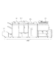
図1は、本発明の実施形態に対応する製本システム(製本装置)の全体構成を示す図である。
(First embodiment)
<Overall configuration of bookbinding system (bookbinding device)>
FIG. 1 is a diagram showing an overall configuration of a bookbinding system (bookbinding apparatus) corresponding to an embodiment of the present invention.
図1において、105は印刷装置であり、画像データに基づいてシートに印刷処理をするとともに、印刷処理されたシートをスタッカ装置104へ搬送する。スタッカ装置104は、印刷装置105から搬送されたシートをスタックトレイ(不図示)に積載する。また、スタッカ装置104は、印刷装置105から搬送されたシートをスタックトレイに積載することなく、くるみ製本装置103へ搬送することもできる。くるみ製本装置103は、印刷装置105からスタッカ装置104を介して搬送される複数のシートSを集積トレイにシート束として積載する。そして、集積トレイに積載されたシート束をカバーシート積載トレイに積載されたカバーシートでくるむことでくるみ製本物を作成する。
In FIG. 1,
なお、くるみ製本装置103は、スタッカ装置104から搬送されたシートSを集積トレイに積載することなく、中綴じ製本装置102へ搬送することもできる。中綴じ製本装置102は、印刷装置105からくるみ製本装置103を介して搬送される複数のシートSからなるシート束S1に対してステイプル処理を実行することで中綴じ製本物を作成する。なお、中綴じ製本装置102にて作成された中綴じ製本物は、断裁装置101に搬送され断裁処理が実行される。
The
<印刷装置の制御構成>
図2は、本発明の実施形態に対応する印刷装置105の制御構成を示すブロック図である。
<Control configuration of printing device>
FIG. 2 is a block diagram showing a control configuration of the
図2において201はスキャナ部であり、複数枚の原稿(紙等のシートに画像が印刷されたもの)を光学的に読み取って画像データを生成するとともに、読み取られた画像データに対して画像処理(例えば、シェーディング補正処理)を実行する。そして、スキャナ部201は、画像処理が実行された複数ページの画像データを1つの印刷ジョブとしてハードディスク(HDD)209へ記憶させる。202は外部I/Fであり、印刷装置105にネットワーク232を介して接続された外部装置としてのコンピュータ端末233から複数ページの画像データを含む印刷ジョブを受信する。そして、外部I/F202は、受信した印刷ジョブをハードディスク209へ記憶させる。203はプリンタ部であり、ハードディスク209に記憶された印刷ジョブに基づいて、複数のシート(用紙)に印刷処理を実行する。なお、印刷ジョブは複数ページの画像データから構成されているので、複数の画像データが複数のシートの各々に印刷処理される。204は操作部であり、印刷装置105の操作者による各種の指示を受け付け、受け付けた指示をメモリコントローラ部206へ伝えることで印刷装置105に各種の設定を行うものである。
In FIG. 2, a
CPU205は、ROM207から読み込んだプログラムをRAM208へ書き込み、RAM208を用いてプログラムを実行することで印刷装置105を含む製本システム2000の全体を制御する。なお、ROM207には、外部I/F202が外部装置から印刷ジョブとして受信したPDL(Page Description language:ページ記述言語)コードデータを解釈するためのプログラムが記憶されている。さらに、ROM207には、PDLコードデータを解釈した後にプリント部203にて印刷可能なデータを生成するためのプログラムが記憶されている。メモリコントローラ部206は、ROM207、RAM208、及びハードディスク209に対する、各部からのアクセスを制御する。
The
圧縮伸長部210は、JBIGやJPEG等といった各種圧縮方式によってRAM208、ハードディスク209に記憶されている画像データに圧縮処理を実行することができる。また、圧縮伸長部210は、各種圧縮方式により圧縮処理された画像データを伸長する伸長処理を実行することができる。
The compression /
回転部231は、ハードディスク209に記憶された画像データをプリンタ部203へ送信して印刷処理を実行させるにあたって、画像データを回転させる必要がある場合に、回転処理を実行するものである。回転部231は、回転処理として、画像データの天地方向を逆転させる180°回転処理や、90°回転処理等の、任意の角度の回転処理を実行することができる。なお、回転部231が実行する回転処理の回転角度の設定等は、CPU205からできるものとする。
The
オプションI/F230は、CPU205が、印刷装置105に接続されるオプション装置としてのスタッカ装置104、くるみ製本装置103、中綴じ製本装置102及び断裁装置101と通信するためのインターフェースである。スタッカ装置104、くるみ製本装置103、中綴じ製本装置102及び断裁装置101は各々内部の動作を制御するためのCPU(不図示)を有する。そして、印刷装置105のCPU205は、オプションI/F230を介して各オプション装置のCPUを制御するための制御コマンドを送信することにより、スタッカ装置104、くるみ製本装置103、中綴じ製本装置102及び断裁装置101を制御する。
The option I / F 230 is an interface for the
<印刷装置の構成>
次に、印刷装置105の構成について、図3を用いて説明する。
<Configuration of printing device>
Next, the configuration of the
印刷装置105は、大きく分けてスキャナ部201およびプリンタ部203から構成される。スキャナ部201は、原稿給送ユニット250に積載されたシート束をその積載順に従って先頭(最上部)から順次1枚ずつプラテンガラス211上に給送する。そして原稿給送ユニット250は、スキャナユニット220による読み取り動作が終了した後、排出トレイ219に排出する。スキャナユニット210は、プラテンガラス211上に原稿シートが搬送されると、ランプ212を点灯して光学ユニット213の移動を開始させ、シート状の原稿を下方から照射しながら走査する。原稿からの反射光が複数のミラー214、215、216およびレンズ217を通ってCCDイメージセンサ(以下、CCD)218に導かれ、走査された原稿上の画像はCCD218によって画像データとして読み取られる。CCD218で読み取られた画像データは、所定の画像処理が施された後、ハードディスク209に記憶される。
The
プリンタ部203は、ハードディスク209から読み出される画像データに対応するレーザ光を、レーザドライバ321によって駆動されるレーザ発光部322から出力する。レーザ光を照射された感光ドラム323にはレーザ光に応じた静電潜像が形成され、現像器324は静電潜像の部分に現像剤(例えば、トナー)を付着させる。
The
一方、レーザ光の照射開始と同期したタイミングで、カセット311、カセット312、カセット313、カセット314、手差しトレイ315の何れかからシートSを給紙し、搬送路331を経由して転写部325まで搬送する。ここで、手差しトレイ315には、シートSが載置されたことを検知するシート検知センサ315aが設けられている。転写部325は感光ドラム323に付着している現像剤をシートS上に転写する。現像剤が転写されたシートSは搬送ベルト326によって定着部327に搬送され、定着部327にて加熱される。それによりシートS上の現像剤は、シートSに定着される。現像剤が定着したシートSは、搬送路335、334を経由してスタッカ装置104に搬送される。スタッカ装置104にシートSを搬送するにあたってシートSを反転させてから搬送する場合、CPU205はシートSを搬送路336、338まで導くようプリンタ部203を制御する。そしてその後に、シートSを逆方向に搬送し、搬送路337、334を経由してスタッカ装置104にシートSを搬送する。
On the other hand, the sheet S is fed from any one of the
次に、図6を参照しつつ、第1の実施形態におけるプリンタ部203の制御構成について説明する。
Next, the control configuration of the
印刷装置105が備えるプリンタ部203は、メモリコントローラ部206を介してCPU205と相互に通信可能となっている。プリンタ部203のCPU2003は、メモリコントローラ部206から画像データと印刷処理を実行するためのコマンドを受信し、受信した画像データを解析してビットデータに変換するとともに、受信したコマンドの解析を行う。
The
プリンタ部203は、CPU2003により制御される各種制御部を備えている。各種制御部としては、シートSを搬送するために印刷装置105が備える各種ローラの制御をするためのシート搬送制御部2004、感光ドラム323を所定電位に帯電するために帯電ローラに印加する電圧を制御するための帯電制御部2005がある。また、CPU203がメモリコントローラ部206から受信した画像データに基づいて感光ドラム323の表面を露光するレーザの走査を制御するためのレーザ走査制御部2006を有する。更に、プリンタ部2003は、感光ドラム323の表面に形成された静電潜像を現像すべく現像器324を制御するための現像制御部2007を有する。更に、プリンタ部203は、感光ドラム323上に形成されたトナー像をシートSに転写するよう転写部325に印加する転写電圧を制御するための転写制御部2008を有する。また、プリンタ部203は、トナー像が転写されたシートS上にトナー像を定着させるよう定着部327を構成するローラ対の回転及びローラ対の少なくとも一方が有するヒータへの投入電力を制御するための定着制御部2009を有する。また、プリンタ部203は、印刷部2へシートSを給紙するようカセット311、カセット312、カセット313、カセット314が備えるローラの駆動を制御するための給紙装置制御部2010を備えている。
The
<操作部の構成>
次に、図4を用いて印刷装置105が備える操作部204の構成について説明する。
<Configuration of operation unit>
Next, the configuration of the
操作部204は、各種ハードキー4−241〜4−246を含むハードキー群4−240を備える。また、操作部204は、液晶表示装置からなるドットマトリックスで構成される液晶表示部4−250を有する。液晶表示部4−250は表面にタッチパネルを備えている。操作部204は、印刷装置105の操作者がキー表示部を押下したことによりキー入力がされたことを検知し、CPU205へキー入力に応じた信号を送信する。そして、CPU205は、ROM207に記憶されたプログラムに基づいて印刷装置105を制御し、受信した信号に応じた動作を実行する。
The
キー4−243は電源キーで、電源のON/OFFをする為のキーである。キー4−244は節電キーで、節電モードにする/節電モードを解除する為のキーである。スタートキー4−241は、スキャナ部201による原稿上の画像の読み取り動作を開始させる指示等の各種処理をスタートさせる指示を操作者に入力させる為のキーである。ストップキー4−242は、印刷装置105を含む製本システム2000により実行中の動作を中止させる指示を操作者に入力させる為のキーである。
A key 4-243 is a power key for turning the power ON / OFF. A key 4-244 is a power saving key, and is a key for setting the power saving mode / releasing the power saving mode. A start key 4-241 is a key for causing an operator to input an instruction to start various processes such as an instruction to start an image reading operation on an original by the
また、キー群4−245は、コピー枚数、ズーム倍率等を入力させる0〜9までのテンキーとその入力をクリアするためのクリアキーを有する。このキー郡4−245で入力されたコピー部数は、液晶表示部4−253に表示される。リセットキー4−246は、液晶表示部4−250やハードキー群4−240を介して操作者により設定された設定条件を初期状態に戻すためのキーである。 The key group 4-245 has ten keys from 0 to 9 for inputting the number of copies, zoom magnification, etc. and a clear key for clearing the input. The number of copies input in the key group 4-245 is displayed on the liquid crystal display unit 4-253. The reset key 4-246 is a key for returning the setting conditions set by the operator via the liquid crystal display unit 4-250 and the hard key group 4-240 to the initial state.
液晶表示部4−250は、CPU205からの指示により、製本システム2000の動作状態等を表示する。液晶表示部4−250には、タッチキーも表示される。液晶表示部4−250において、キー4−252は、印刷装置105が印刷処理に用いるシートS(用紙)が積載されたカセットを選択するキーである。CPU205は、このキーが操作者により押下されると、液晶表示部4−250に図5に示す用紙選択画面を表示するよう操作部204を制御する。
The liquid crystal display unit 4-250 displays an operation state of the
図5(a)に示す用紙選択画面のキー群4−271で印刷処理に用いるカセット(カセット311〜315のいずれか)が選択される。そして、CPU205は、閉じるキー4−270が操作者により押下されると、この画面は閉じて図4の画面に戻し、選択されたカセットを表示部4−251に表示させる。
A cassette (one of the
図4のキー4−258、4−262は、濃度調整を行うためのキーである。CPU205は、これらのキーにより調整される濃度を表示部4−263に表示させる。キー4−259は、自動濃度調整機能をON/OFFするためのキーである。キー4−261は写真モード/テキストモード等の設定を行うためのキーである。
Keys 4-258 and 4-262 in FIG. 4 are keys for adjusting the density. The
キー4−254,キー4−255は、それぞれ等倍,縮小/拡大を設定するためのキーである。キー4−255が押下されると、CPU205は液晶表示部4−250に、図5(b)に示す倍率画面を表示させ、拡大縮小を詳細に設定可能にする。図に示す倍率画面のキー群4−273で倍率が選択され、閉じるキー4−272が操作者により押下されると、CPU205はこの画面は閉じて図4の画面に戻す。そして、CPU205は、設定された倍率を表示部4−251に表示させる。
Keys 4-254 and 4-255 are keys for setting equal magnification and reduction / enlargement, respectively. When the key 4-255 is pressed, the
キー4−257は両面キーで、キー4−257が押下されると、CPU205は液晶表示部4−250に、図5(c)に示す両面印刷設定画面を表示させる。以下、両面印刷の設定に関して図5(c)を参照して説明する。
A key 4-257 is a double-sided key. When the key 4-257 is pressed, the
図5(c)において、キー4−280は、片面にのみ画像が印刷された原稿(以下、片面原稿)を用いてシートの両面に印刷処理するための設定キーである。そして、キー4−281は、両面に画像が印刷された原稿(以下、両面原稿)を用いてシートの両面に印刷処理するための設定キーである。キー4−283は、両面原稿をもちいてシートの片面のみに印刷処理するための設定キーである。また、キー4−284は、ページ連写両面を行うための設定キーである。 In FIG. 5C, a key 4-280 is a setting key for performing printing processing on both sides of a sheet using a document on which an image is printed only on one side (hereinafter referred to as a single-sided document). A key 4-281 is a setting key for performing printing processing on both sides of a sheet using an original on which images are printed on both sides (hereinafter referred to as a double-sided original). A key 4-283 is a setting key for printing on only one side of a sheet using a double-sided document. A key 4-284 is a setting key for performing page continuous double-sided copying.
キー4−285は、図5(c)の両面印刷設定画面において操作者によりなされた設定を有効にするためのキーである。このキーが押下されると、CPU205は、図5(c)の両面印刷設定画面での設定を有効にし、液晶表示部4−250の表示を図4の画面に戻す。また、キー4−282は、図5(c)において行った設定を取り消すためのキーであり、このキーが押下されると、CPU205は、図5(c)の両面印刷設定画面での設定を無効にし、液晶表示部4−250の表示を図4の画面に戻す。
A key 4-285 is a key for validating the setting made by the operator on the duplex printing setting screen of FIG. When this key is pressed, the
図4の表示画面上のキー4−256は、印刷装置105が印刷処理した用紙(シート)を製本システム2000における何れの装置に排紙するかをユーザにより入力可能にする為のキーである。
A key 4-256 on the display screen in FIG. 4 is a key for allowing the user to input to which apparatus in the
図7は、給紙カセット(カセット311〜315のいずれか)に積載するシートSのサイズを指定するための操作画面である。図7の操作画面は、図5(a)にて給紙カセットのいずれか1つ(カセット311〜315のいずれか)が選択された後に表示される画面である。図7の画面上のキー群701は、図5(a)にて選択されたシートに積載するシートのサイズを操作者により設定させる為のキーである。例えば、操作者により、図7の画面上の「A4」サイズが押下され「次へ」キーが押下されると、CPU205は、液晶表示部4−250に図8に示す操作画面を表示させる。
FIG. 7 is an operation screen for designating the size of the sheet S to be stacked on the paper feed cassette (any of the
図8は、給紙トレイに積載される用紙の種類を設定するための操作部204の表示画面を示す図である。
FIG. 8 is a diagram showing a display screen of the
図8において801〜808のいずれかを押下することにより、用紙種類を設定する。そして、印刷装置105の使用者がキー810を押下することで、用紙の種類が確定し、図5(a)の操作画面に戻る。
In FIG. 8, the paper type is set by pressing any one of 801 to 808. Then, when the user of the
以上のように図5(a)にて選択されたカセットに積載される用紙について、図7で用紙サイズが設定され、図8で用紙種類が設定される。そして、CPU205は、設定された用紙に付与された用紙IDを各々の給紙トレイに対応付けてHDD209に給紙トレイ情報として記憶させる。給紙トレイ情報の一例を示したものが、図14である。例えば、コンピュータ端末233から印刷ジョブを受信して印刷処理を実行する場合に、給紙トレイ(給紙元)のみを指定した印刷ジョブがコンピュータ端末233にて生成される場合がある。このような場合、印刷ジョブには給紙トレイを特定する情報が含まれているので、CPU205は図14の給紙トレイを参照することで、印刷処理で用いる用紙の種類を特定することができる。
As described above, for the paper stacked in the cassette selected in FIG. 5A, the paper size is set in FIG. 7, and the paper type is set in FIG. Then, the
次に、HDD209に記憶される用紙情報について説明する。
Next, paper information stored in the
印刷装置105は、プリンタ部203にて印刷処理を実行するにあたって、各種の制御情報を用いて印刷処理を実行する。ここでいう制御情報とは、定着部327を加熱する際の温度値や、転写部325にて印加する転写電圧値や、用紙をプリンタ部203にて搬送させる際の搬送速度値(印刷速度値)等のプリンタ部203の各部を制御するための情報をいう。印刷装置105は、様々な種類の用紙を用いて印刷処理を実行することが想定されるが、どのような種類の用紙を用いた場合でも一定の印刷結果が得られることが望まれる。そこで、印刷装置105は、用紙情報に制御情報をも含ませておくことで、用紙の種類に応じて転写電圧、印刷速度及び定着温度を適切に制御する。
When the
用紙情報について、本実施形態においては、Type1、Type2及びType3という3つのタイプの用紙情報が存在する。 Regarding the paper information, in the present embodiment, there are three types of paper information of Type1, Type2, and Type3.
まず、用紙情報の1種であるType1の用紙情報について説明する。
First,
Type1とは、印刷装置105のHDD209に予め(例えば、製造時)記憶されている用紙情報であり、図9に示すようなテーブルとしてHDD209に記憶されている。図9のテーブルにおいて、IDとは複数種類のType1の用紙を識別するための情報であり、印刷装置105のCPU205は、このIDにより用紙の種類を判別する。用紙名称とは、用紙に与えられた名称を示すものである。また坪量とは、用紙の1m2辺りの重量を示すものであり、表面性とは用紙の表面の材質を示すものである。なお、用紙の坪量と、用紙の材質は、用紙そのものの特性を示す情報であるので、用紙特性情報と呼ぶ。
また、定着温度は定着部327を加熱する際の温度値であり、印刷速度はプリンタ部203にて印刷処理を実行するにあたって用紙を搬送させる際の搬送速度値である。また、転写電圧は、転写部325にて用紙に印加する転写電圧値を示すものである。Type1の用紙情報に含まれる用紙は、印刷装置105の操作部204から印刷処理に用いる用紙として選択することができる。具体的には、Type1の用紙情報に含まれる用紙は、図8の操作画面にて選択できるようになっている。図9の例では、印刷装置105のHDD209にType1の用紙として8種類の用紙が登録されている場合を示したが、8種類に限らず任意の種類をType1として予め登録しておくようにしても良い。
The fixing temperature is a temperature value when the fixing
次に、用紙情報の1種であるType3の用紙情報について説明する。
Next,
Type3とは、印刷装置105のHDD209に予め(例えば、製造時)記憶されている用紙情報であり、この点ではType1の用紙情報と同じである。しかし、Type3がType1と異なる点は、Type3の用紙情報に含まれる用紙が、印刷装置105の印刷処理に用いる用紙として図8の画面にて選択することができない点である。つまり、Type3の用紙情報に含まれる用紙は、印刷装置105による印刷処理には用いることができず、後述するType2の用紙情報として登録することで、初めて印刷処理に用いることができるようになる。印刷処理に用いる用紙は数千種類のものが市場に存在するが、これら全ての種類の用紙について印刷装置105の印刷処理にて用いることができるようにするのは問題がある。具体的には、図8のような操作画面にて、数千種類の用紙の中から所望の用紙を選択するのは困難である。そこで、印刷装置105は、Type3の用紙の中から印刷装置105の使用者が必要とする種類の用紙だけを印刷処理にて用いることができるようにする。
具体的には、Type3の用紙情報に含まれる用紙を印刷装置105による印刷処理に用いることができるようにする場合、印刷装置105の使用者は、図8の操作画面において、用紙の登録キー810を押下する。CPU205は、用紙の登録キー810が押下されたことに応じて、図12に示す操作画面を操作部204に表示させる。図12の操作画面においては、Type3に含まれる用紙が選択できる。図12に示した例では、Type3の中でIDが0234−0000〜0241−0000に相当する8種類の用紙が選択できるように表示されている。この8種類の用紙を特定する部分(1201〜1208)が押下され、OKキー1209が押下されると、図8において選択できる用紙として新たな用紙がType2の用紙情報として登録される。このような登録が行われることで、印刷装置105が印刷処理に用いることができる用紙が新たに登録(追加)されることとなる。なお、図12の例では8種類のType3に含まれる用紙が選択できるものとしたが、Type3には図10に示す1000種類の用紙が含まれるので、図12の画面においては、用紙情報をスクロール表示させることで1000種類の用紙のいずれかが選択できるものとする。
Specifically, when the paper included in the paper information of
次に、用紙情報の1種であるType2の用紙情報について説明する。
Next,
Type2の用紙情報に含まれる用紙とは、Type3に含まれる用紙のうち、図12の画面を用いた登録処理により新たに印刷装置105が印刷処理に使用できるものとなった用紙のことをいう。また、Type1に含まれる用紙を複製して新たにType2の用紙として登録することもできる。複製を行う場合は、図8の操作画面にてType1に含まれる用紙を選択した状態で、複製キー812を押下すればよい。キー812を押下すると、Type1の用紙とは別にType2の用紙として新たな用紙が追加される。Type2の用紙情報の一例を示したものが図11である。なお、Type1から複製したType2の用紙は、Type1の用紙と同じ用紙情報となるが、用紙名称については重複しないように書き換えられる。なお、Type2に含まれる用紙については、図8にて編集キー811を押下することで、用紙の編集をすることが可能である。一例として、図9に示すType1の用紙情報の中からIDが0002−0000の用紙情報をType2の用紙情報として新たに登録(複製)した場合について説明する。この場合、図8のキー802を押下した状態で複製キー812を押下することで新規の用紙情報がType2に登録(複製)される。そして、Type2として登録された用紙を図8の画面にて選択した後に編集キー811を押下すると、図13の操作画面が操作部204に表示される。ここで、印刷装置105の操作者は、変更キー1301を押下してその後に表示される画面(不図示)にて操作部204を用いた文字入力を行うことで、用紙情報のうち用紙名称情報を変更することができる。また、印刷装置105の操作者は、変更キー1302を押下してその後に表示される画面(不図示)にて操作部204を用いた数値入力を行うことで、用紙情報のうち坪量情報を変更することができる。また、印刷装置105の操作者は、変更キー1303を押下してその後に表示される画面(不図示)にて操作部204を用いた選択処理(上質、再生、コートのいずれかの選択処理)を行うことで、用紙情報のうち表面性情報を変更することができる。また、印刷装置105の操作者は、変更キー1304を押下してその後に表示される画面(不図示)にて操作部204を用いた数値入力を行うことで、用紙情報のうち定着温度情報を変更することができる。また、印刷装置105の操作者は、変更キー1305を押下してその後に表示される画面(不図示)にて操作部204を用いた数値入力を行うことで、用紙情報のうち印刷速度情報を変更することができる。また、印刷装置105の操作者は、変更キー1306を押下してその後に表示される画面(不図示)にて操作部204を用いた数値入力を行うことで、用紙情報のうち転写電圧情報を変更することができる。
The sheet included in the sheet information of
なお、以上の変更処理は、CPU205が、操作部204に入力された情報に基づいて、HDD209に記憶されたType2の用紙情報を書き換えることにより実行される。また、以上の変更処理の結果として操作部204には、印刷装置105が印刷処理に用いることができる用紙として、Type1とType2の用紙情報を含むものが表示される。
The above change processing is executed by the
次に、印刷装置105が印刷処理可能な印刷設定項目の組み合わせを示す設定許可情報について説明する。
Next, setting permission information indicating combinations of print setting items that can be printed by the
スキャナ部201から入力される画像データを用いてプリンタ部203で印刷処理をする場合、印刷装置105の使用者は、複数の印刷設定項目の設定をしたうえで印刷処理を実行させる。ここで、複数の印刷設定項目を設定可能な印刷装置105においては、複数の印刷設定項目の組み合わせが印刷装置にて実行不可能な設定となってしまうことがある。そこで、複数の印刷設定項目について、設定可能となる組み合わせを示す情報として設定許可情報を予め記憶しておき、印刷装置が印刷処理できないような印刷設定がなされないようにする。図15は、設定許可情報を示すテーブルであり、用紙タイプ毎に複数組の設定許可情報が存在する。印刷設定項目として、図15には、両面印刷が可能か否かを設定する項目、用紙の給紙元として利用可能なカセットを設定する項目及び用紙の排紙先として利用可能な装置を設定する項目がある。また、設定許可情報は用紙サイズが異なる場合には、同じ用紙タイプであっても異なる設定情報が存在する。例えば、A4サイズの普通紙については、断裁装置101が用紙の排紙先として選択できないものの、両面印刷可能であり、いずれのカセット(又は手差し)であっても給紙元として選択可能であり、スタッカ装置104やくるみ製本装置103や中綴じ製本装置102のいずれも選択可能である。なお、図15に記載されているように、用紙種類としては、Type1の用紙情報に相当するものが用意されている。また、これらの複数組の設定許可情報は、HDD109に記憶されている。
When the
なお、設定許可情報としてType1に相当する情報だけでなく、Type2及びType3の用紙情報に対して予め用意しておくのは困難である。例えば、Type3の用紙情報として本実施形態では1000種類もの用紙が存在するので、それら全種類について設定許可情報を用意しておくのは困難である。そこで、本実施形態では、印刷処理するための複数の印刷設定項目について各印刷設定項目にて設定可能な内容の組み合わせを示す設定許可情報を用紙種類に応じて増加させることなく、適切に複数の印刷設定項目の印刷設定を実行することができるようにする。具体的には、CPU205は、図16のテーブルを用いてType2の用紙情報に対して、図15における複数組の設定許可情報の中からいずれか1つの設定許可情報を選択することで、複数の設定許可情報を増加させることなく、適切に複数の印刷設定項目の印刷設定を実行する。図16は、Type2の用紙情報をType1の用紙情報と対応付けるためのテーブルである。
It is difficult to prepare not only information corresponding to
次に、図17を用いて、CPU205がType2の用紙情報に対して図15にあるType1に対応付けられた複数の設定許可情報のいずれかを選択し、印刷処理を実行する動作を説明する。図17は、CPU205がHDD209に記憶された制御プログラムに基づいて実行される動作である。
Next, an operation in which the
図17のステップS1701でCPU205は、図5(a)の操作画面を介して使用者により選択された給紙元(カセット311〜314及び手差し315のいずれか)を印刷処理に用いる用紙の給紙元として選択する。
In step S1701 in FIG. 17, the
ステップS1702で、CPU205は、図5(a)の操作画面に引き続いて表示される図7の操作画面にて使用者により選択された用紙サイズを、印刷処理に用いる用紙の用紙サイズとして選択(指定)する。
In step S1702, the
ステップS1703で、CPU205は、図7の操作画面に引き続いて表示される図8の操作画面にて使用者により選択された用紙種類を、印刷処理に用いる用紙の用紙種類として選択する。なお、図8の例では、操作画面にはType1に相当する用紙情報しか表示されていないが、このステップでは、用紙情報を表示する画面をスクロールさせ、Type2として登録されている図11の“ABC Coated 1”(ID=0236−0001)が選択されたものとする。
In step S1703, the
ステップS1704で、CPU205は、ステップS1703にて選択した用紙種類に対応する用紙情報、図15及び図16のテーブルを参照し、ステップS1703にて選択した用紙種類に対応する設定許可情報を選択する。具体的には、CPU205は、ステップS1703にて選択した用紙種類の坪量が200g/m2であり、表面性がコートであることから、図16にて“コート紙2”を選択し、更に“コート紙2”に対応する設定許可情報を図15にて選択する。ステップS1704で、CPU205が選択した設定許可情報では、両面印刷が使用不可、くるみ製本装置が使用不可、断裁装置が使用不可となっている。
In step S1704, the
ステップS1705で、CPU205は、ステップS1704で選択した設定許可情報に基づいて他の印刷設定を行う。ここでは、印刷設定項目として両面印刷の設定項目、排紙先の設定項目について説明する。まず、両面印刷の設定を行う場合は、図4の操作画面において、キー4−257を押下する。そうすると、CPU205は、操作部204に図5(c)に示す操作画面を表示させる。ここで、ステップS1704で選択した設定許可情報では、両面印刷の設定が不可となっているので、CPU205は、図5(c)に示す操作画面では、キー4−280及びキー4−281が押下できないようにする。即ち、CPU205は、Type2の“ABC Coated 1”を印刷処理にて使用する場合は、両面印刷処理が実行できないように制御する。次に、排紙先の設定を行う場合は、図4の操作画面において、キー4−256を押下する。そうすると、CPU205は、操作部204に図18に示す操作画面を表示させる。ここで、ステップS1704で選択した設定許可情報では、排紙先として断裁装置101の設定が不可となっているので、CPU205は、図18に示す操作画面では、キー1804が押下できないようにする。即ち、CPU205は、Type2の“ABC Coated 1”を印刷処理にて使用する場合は、排紙先として断裁装置101が指定できないように制御する。なお、CPU205は、図18に示す操作画面にて印刷装置105の使用者が排紙先としてスタッカ装置104、くるみ製本装置103又は中綴じ製本装置102を選択した場合、各装置において用紙に対する処理を設定するための操作画面(不図示)を操作部204に表示させる。
In step S1705, the
ステップS1706で、CPU205は、ステップS1701〜ステップS1705の各ステップにおいて設定した印刷設定に基づいて、プリンタ部203に印刷処理を実行させる。なお、ステップS1706は、スキャナ部201の原稿給送ユニット250にシート束が積載された状態で図4のキー4−241を印刷装置105の使用者が押下したことを、CPU205が検知することにより開始される。なお、プリンタ部201を制御するCPU2003は、図17のS1703で選択された用紙種類に対応する用紙情報に基づいて、プリンタ部2003の各部を制御する。ステップS1703では、用紙種類として“ABC Coated 1”(ID=0236−0001)が選択されたので、図11に示すように用紙情報には、定着温度が191℃、印刷速度が200mm/sec、転写電圧が1.2KVとなっている。そこで、CPU2003は、印刷処理時の定着部327の定着温度が191℃となるよう定着制御部2009を制御する。また、CPU2003は、印刷処理時の用紙の搬送速度が200mm/secとなるよう、シート搬送制御部2004を制御する。また、CPU2003は、印刷処理時の転写部325の転写電圧が1.2KVとなるよう転写制御部2008を制御する。このように、用紙情報には、印刷処理を実行する際のプリンタ部203に対する各種の設定情報が含まれているため、印刷装置105は、用紙の種類に応じた適切な印刷処理を実行することができる。
In step S1706, the
以上説明したように、本実施形態においては、印刷装置105にて使用可能な用紙の種類としてType1の用紙情報に対応するものに加えて、新たな用紙情報をType3から登録してType2の用紙情報を登録(生成)することができる。また、Type1の用紙情報の中から新たにType2の用紙情報を生成することができる。これにより、印刷装置105で、Type1の用紙情報とType2の用紙情報のいずれかに対応するものが印刷処理に使用可能になる。そして、Type2の用紙情報に対応する用紙については、印刷処理をするための複数の印刷設定項目について各印刷設定項目にて設定可能な内容の組み合わせを示す設定許可情報を、Type2の用紙情報に対して設けられている設定許可情報の中から選択することができる。
As described above, in this embodiment, in addition to the type of paper that can be used by the
そして、以上説明したような本実施形態によれば、印刷装置が使用可能な用紙情報を新たに登録(追加)した場合であっても、印刷処理するための複数の印刷設定項目について各印刷設定項目にて設定可能な内容の組み合わせを示す設定許可情報を増加させることがない。また、印刷装置が使用可能な用紙情報を新たに登録(追加)した場合であっても、適切な設定許可情報を選択することで、適切に複数の印刷設定項目の印刷設定を実行することができる。 According to the present embodiment as described above, even when paper information that can be used by the printing apparatus is newly registered (added), each print setting is set for a plurality of print setting items for print processing. Setting permission information indicating a combination of contents that can be set in the item is not increased. Further, even when paper information that can be used by the printing apparatus is newly registered (added), it is possible to appropriately execute print settings for a plurality of print setting items by selecting appropriate setting permission information. it can.
(第2の実施形態)
次に、本発明にかかる第2の実施形態について説明する。
(Second Embodiment)
Next, a second embodiment according to the present invention will be described.
第2の実施形態は第1の実施形態の変形例である。第1の実施形態では、プリンタ部203が印刷処理を実行するのに用いる画像データは、スキャナ部201から入力されたものであったが、第2の実施形態では外部装置であるコンピュータ端末233から外部I/F202を介して入力される点が異なる。
The second embodiment is a modification of the first embodiment. In the first embodiment, the image data used by the
図19は、外部装置としてのコンピュータ端末233の構成を示す図である。
FIG. 19 is a diagram illustrating a configuration of a
図19において、コンピュータ端末233は、ROM903のプログラム用ROMあるいは外部メモリ911に記憶された文書処理プログラム等に基づいて図形、イメージ、文字、表(表計算等を含む)等が混在した文書処理を実行するCPU901を備える。CPU901は、システムバス904に接続される各バスデバイスを総括的に制御する。また、ROM903のプログラム用ROMあるいは外部メモリ911には、CPU901の制御プログラムであるオペレーティングシステムプログラム(以下OS)や後述するプリンタドライバ等が記憶されている。ROM903のフォント用ROMあるいは外部メモリ911には文書処理の際に使用するフォントデータ等が記憶されている。また、ROM903のデータ用ROMあるいは外部メモリ911には文書処理等を行う際に使用する各種データが記憶される。RAM902は、CPU901の主メモリ、ワークエリア等として機能する。
In FIG. 19, the
キーボードコントローラ(KBC)905は、キーボード909や不図示のポインティングデバイスからのキー入力を制御する。CRTコントローラ(CRTC)906は、CRTディスプレイ(CRT)910の表示を制御する。ディスクコントローラ(DKC)907は、ハードディスク(HD)、フロッピー(登録商標)ディスク(FD)等の外部メモリ911とのアクセスを制御する。外部メモリ911は、ブートプログラム、各種のアプリケーション、プリンタ制御コマンド生成プログラム(以下プリンタドライバ)等を記憶する。プリンタコントローラ(PRTC)908は、ネットワーク232を介して印刷装置105に接続されて、印刷装置105との通信制御処理を実行する。
A keyboard controller (KBC) 905 controls key input from a
図25は、コンピュータ端末233のソフトウェア構成図である。アプリケーション1001、グラフィックエンジン1002、プリンタドライバ1003、およびシステムスプーラ1004は、外部メモリ911に保存されたソフトウェアプログラムとして存在する。
FIG. 25 is a software configuration diagram of the
外部メモリ911に保存されているアプリケーション1001は、RAM902にロードされて実行される。そして、アプリケーション1001から印刷装置105に対して印刷ジョブを送信する際には、RAM902にロードされ実行可能となっているグラフィックエンジン1002を利用して出力(描画)を行う。
The
グラフィックエンジン1002が出力したデータは、プリンタドライバ1003に渡される。プリンタドライバ1003は、外部メモリ911からRAM2にロードされ、CPU901により実行されるものである。そして、プリンタドライバ1003は、グラフィックエンジン1002から渡されたデータを印刷装置105が解釈可能な制御コマンド(例えば、PDLコマンド)に変換する。制御コマンドは、OSによってRAM902にロードされたシステムスプーラ1004を経てネットワーク232経由で印刷装置105へ出力される仕組みとなっている。そして、このような制御コマンドを、印刷ジョブと呼ぶものとする。
Data output from the
なお、プリンタドライバ1003による印刷ジョブの生成を行うためには、印刷装置105における印刷処理条件(印刷処理に用いるシートの種類、両面・片面印刷の指定等の印刷設定項目の組み合わせを示すもの)を設定する必要がある。この設定は、通常プリンタドライバ203が提供するウィンドウ(CRT910上に表示するもの)から行う。そして、プリンタドライバ203は、ウィンドウを介してコンピュータ端末233の操作者が設定した内容を印刷ジョブに印刷処理条件として付加する。
In order to generate a print job by the
図20は、コンピュータ端末233にインストールされているプリンタドライバ1003が印刷処理設定項目を設定するためのウィンドウを示す図である。
FIG. 20 is a view showing a window for the
コンピュータ端末233は、アプリケーション1001にて文書を作成している際に、プリンタドライバ1003を起動させることで図20の設定画面をCRT910に表示させる。
The
図20の設定画面において、コンピュータ端末233の操作者(使用者)は、プリンタ名選択ボックス1101を不図示のポインティングデバイス等を用いて操作する。この操作により、コンピュータ端末233が印刷ジョブを送信する送信先として、印刷装置105又は他の印刷装置が選択される。図20においてコンピュータ端末233は、印刷装置105を選択している。また、コンピュータ端末233を操作する操作者は、印刷範囲選択ボックス1102を、ポインティングデバイス等を用いて操作する。これにより、アプリケーション1001が生成する文書のうち所望のページが印刷装置105にて印刷すべき範囲として決定する。プリンタドライバ1003は、操作者が「すべて」を選択した場合には、アプリケーション1001が生成した文書の全てのページを印刷対象とする。また、プリンタドライバ1003は、操作者が「現在のページ」を選択した場合には、アプリケーション1001が生成した複数ページの文書のうち現在CRT910上に表示されているページを印刷対象とする。また、プリンタドライバ1003は、操作者が「ページ指定」を選択した場合には、アプリケーション1001が生成した複数ページの文書のうちエディットボックス1103に入力されているページを印刷対象とする。また、プリンタドライバ1003は、操作者が印刷部数設定ボックス1104に入力した部数を印刷対象の部数にする。
On the setting screen of FIG. 20, the operator (user) of the
そして、コンピュータ端末233の操作者は、印刷装置105へ送信する印刷ジョブの印刷処理条件の設定が終了したならばOKボタン1106を押下する。それにより、プリンタドライバ1003は、印刷ジョブの生成を開始する。なお、コンピュータ端末233の操作者は、印刷ジョブの生成を中止する場合には、キャンセルボタン1107を押下する。
Then, the operator of the
図21は、図20のプリンタドライバのプロパティ設定画面においてプロパティボタン1105を押下したときに表示される画面を示す図である。 FIG. 21 is a diagram showing a screen displayed when the property button 1105 is pressed on the property setting screen of the printer driver of FIG.
コンピュータ端末233を操作する操作者は、原稿サイズ選択ボックス2101を不図示のポインティングデバイス等を用いて操作する。この操作により、プリンタドライバ1003は、アプリケーション1001が編集する文書における各ページの原稿サイズを選択する。なお、通常はアプリケーション1001が編集する文書には原稿サイズが指定されているので、この原稿サイズが自動的に選択される(図21ではA4)。また、プリンタドライバ1003は、操作者が出力用紙サイズ選択ボックス2102について「原稿サイズと同じ」を選択した場合には、印刷装置105にて印刷処理(出力処理)に用いるシートのサイズとしてA4サイズを選択する。なお、操作者は出力用紙サイズとして、「原稿サイズと同じ」を選択する以外にも「A3サイズ」、「B5サイズ」等の所望のシートサイズを選択することができる。ただし、この場合は、原稿サイズと異なるサイズが選択されるので、プリンタドライバ1003は、倍率を変更しつつ印刷ジョブを生成する。また、プリンタドライバ1003は、操作者が部数選択ボックス1203について所望の印刷部数を入力したことに応じて入力された部数を印刷ジョブに設定する。また、プリンタドライバ1003は、操作者が印刷方向指定ボックス1204にて選択した印刷方向を入力する。
An operator who operates the
そして、操作者がOKボタン2105を選択したことにより原稿サイズ選択ボックス2101、出力用紙サイズ選択ボックス2102、部数選択ボックス2103、印刷方向指定ボックス2104に入力されている値を確定する。一方、操作者がキャンセルボタン1206を選択したことによりボックス2101〜2104に入力されている値を確定せずに予め定められている初期設定に戻す。
Then, when the operator selects the
図22は、図20のプリンタドライバ1003のプロパティ設定画面において仕上げタブ2108が選択されたときに表示される画面を示す図である。
FIG. 22 is a diagram showing a screen displayed when the
コンピュータ端末233を操作する操作者は、印刷方法選択ボックス2201を不図示のポインティングデバイス等を用いて操作する。この操作により、プリンタドライバ1003は、印刷ジョブを印刷装置105にて印刷処理させるときのの印刷方法(印刷処理条件の1つ)を選択する。なお、印刷方法としては、シートの片面のみに印刷処理をする「片面印刷」、シートの両面に印刷処理をする「両面印刷」等がある。
An operator who operates the
また、コンピュータ端末233を操作する操作者は、シート処理選択ボックス2204を不図示のポインティングデバイス等を用いて操作する。この操作により、プリンタドライバ1003は、印刷装置105にて印刷処理されたシートを排紙する排紙先の装置を選択する。選択できる排紙先の装置としては、スタッカ装置104、断裁装置101、中綴じ製本装置102、くるみ製本装置103がある。
An operator who operates the
そして、操作者がOKボタン2202を選択したことにより印刷方法選択ボックス2201及びシート処理選択ボックス2204に入力されている値を確定する。一方、操作者がキャンセルボタン2203を選択したことにより印刷方法選択ボックス2201及びシート処理選択ボックス2204に入力されている値を確定せずに予め定められている初期設定に戻す。
Then, when the operator selects the
図23は、図21のプリンタドライバ1003のプロパティ設定画面において給紙タブ2109が選択されたときに表示される画面を示す図である。
FIG. 23 is a diagram showing a screen displayed when the
コンピュータ端末233を操作する操作者は、用紙の給紙方法選択ボックス2301を不図示のポインティングデバイス等を用いて操作する。この操作により、プリンタドライバ1003は、印刷ジョブを印刷装置105にて印刷処理させるときに用いる用紙の指定方法を選択する。なお、図23の例では、用紙の指定方法として用紙種類で指定する方法が選択されている。そして、用紙種類で指定する方法が選択された場合、用紙種類を指定するための表示2302がされる。なお、2302に表示される用紙としては、プリンタドライバ1003がコンピュータ端末233にインストールされた時点においては、前述したType1に相当する用紙だけが表示されることとなる。しかし、前述した通り、使用者がType3の用紙情報を新たにType2の用紙情報として登録することにより、印刷装置105は新たな用紙を印刷処理に使用することが可能となる。ところが、コンピュータ端末1003のプリンタドライバ1003は、印刷装置105から、印刷装置105にて新たに登録された用紙に関する用紙情報を取得しなければ、Type2の用紙を印刷処理で使用する用紙として選択することができない。そこで、図23の画面には用紙情報取得キー2303が設けられている。コンピュータ端末23を操作する操作者は、用紙情報取得キー2303をポインティングデバイスにてクリックすることにより、印刷装置105からType2の用紙情報(図11に示すテーブル)をコンピュータ端末233の外部メモリ911に転送させることができる。そして、コンピュータ端末233のプリンタドライバ1003は、外部メモリ911に記憶されたType2の用紙情報と、予めプリンタドライバ1003が情報として持っているType1の用紙情報とを、2302として表示させることができる。コンピュータ端末23を操作する操作者は、表示2302の中から印刷ジョブを印刷処理させるのに用いる用紙種類をポインティングデバイスで指定する。そして、操作者がOKボタン2304を選択したことにより用紙種類を確定する。
An operator who operates the
以上の図21、図22、図23のプリンタドライバのプロパティ設定画面における設定が終了すると(OKボタン2105、OKボタン2202、OKボタン2304が押下されると)、図20のプリンタドライバの設定画面に戻る。
When the setting on the property setting screen of the printer driver of FIGS. 21, 22, and 23 is completed (when the
そして、図20のプリンタドライバの設定画面におけるOKボタン1106が押下されると、外部装置は、プロパティ設定画面において設定された設定内容と、アプリケーションデータとを合成して1つの印刷ジョブを生成する。さらに、コンピュータ端末233は、印刷ジョブを印刷装置105へ送信する。
When the
なお、印刷ジョブのデータ構造の具体例を図24に示す。 A specific example of the data structure of the print job is shown in FIG.
図24は、コンピュータ端末233が印刷装置105に送信する印刷ジョブのデータ構造を示す図である。
FIG. 24 is a diagram illustrating a data structure of a print job transmitted from the
図24において2401は印刷ジョブIDであり、コンピュータ端末233が印刷装置105に印刷ジョブを送信する場合に、印刷ジョブを特定できるよう印刷ジョブに付与される固有のIDである。また、2402は出力方法指定情報であり、印刷方法選択ボックス1301にて選択された印刷方法を特定する情報である。また、2403は給紙部指定情報であり、給紙部選択ボックス(2301にて“給紙元で指定”が選択された場合に表示されるボックス)にて選択された給紙部を特定する情報である。また、2404は用紙情報であり、出力用紙サイズ選択ボックス1202にて選択された出力用紙サイズを特定する用紙サイズ情報を含む情報である。また、用紙情報には、用紙種類を示す用紙種類情報も含む。図23の表示2302にて選択された用紙種類が“カスタム普通紙1”であった場合、用紙種類情報は用紙ID(0002−0001)となる。
In FIG. 24,
また、2405は印刷部数指定情報であり、印刷部数設定ボックス1104にて入力された印刷部数を特定する情報である。また、2406は、印刷ジョブ名であり、アプリケーションにて管理する際のファイル名を示すテキストデータが印刷ジョブ名として付与されている。そして、2407は、ドキュメントデータであり、コンピュータ端末233上で動作するアプリケーションにて生成されたドキュメント(文書)のデータである。
なお、コンピュータ端末233は、印刷設定項目の組み合わせを示す設定許可情報としてType1の用紙情報(図15)に相当するものを外部メモリ911に記憶している。また、図16のテーブルも外部メモリ911に記憶している。そして、第1の実施形態において印刷装置105が実行していたのと同様に、プリンタドライバ1003は、外部メモリ911に記憶された設定許可情報に基づいて印刷装置105が印刷処理できないような印刷設定がされないようにする。
The
ここで、図26を用いて、プリンタドライバ1003がType2の用紙情報に対して図15にあるType1に対応付けられた複数の設定許可情報のいずれかを選択し、印刷ジョブを生成する動作を説明する。図26は、CPU901により動作するプログラムとしてのプリンタドライバ1003が実行する動作である。
Here, with reference to FIG. 26, an operation in which the
図26のステップS2601でプリンタドライバ1003は、図21画面にて選択された出力用紙サイズを、印刷処理に用いる用紙の用紙サイズとして選択する。
In step S2601 of FIG. 26, the
ステップS2602で、プリンタドライバ1003は、図23の画面にて使用者により選択された用紙種類を、印刷処理に用いる用紙の用紙種類として選択する。なお、図23の例では、Type2として登録されている“カスタム普通紙1”(ID=00002−0001)が選択されたものとする。
In step S2602, the
ステップS2603で、プリンタドライバ1003は、ステップS2603にて選択した用紙種類に対応する用紙情報、図15及び図16のテーブルを参照し、ステップS2502にて選択した用紙種類に対応する設定許可情報を選択する。具体的には、プリンタドライバ1003は、ステップS2602にて選択した用紙種類の坪量が95g/m2であり、表面性が上質であることから、図16にて“普通紙”を選択し、更に“普通紙”に対応する設定許可情報を図15にて選択する。ステップS2603で、プリンタドライバ1003が選択した設定許可情報では、断裁装置が使用不可となっている。
In step S2603, the
ステップS2604で、プリンタドライバ1003は、ステップS2603で選択した設定許可情報に基づいて他の印刷設定を行う。ここでは、印刷設定項目として両面印刷の設定項目、排紙先の設定項目について説明する。まず、両面印刷の設定を行う場合は、図22の画面において、印刷方法選択ボックス1301において両面印刷を選択する。ここで、ステップS2603で選択した設定許可情報では、両面印刷の設定が可となっているので、プリンタドライバ1003は、図22の画面では、両面印刷が選択できるようにする。即ち、CPU205は、Type2の“カスタム普通紙1”を印刷処理にて使用する場合は、両面印刷処理が実行できるように制御する。次に、排紙先の設定を行う場合は、図22の画面において、シート処理選択ボックス1304にて排紙先として指定する装置を選択する。ここで、ステップS2603で選択した設定許可情報では、排紙先として断裁装置101の設定が不可となっているので、プリンタドライバ1003は、図22の画面では、断裁装置101が排紙先として選択できないようにする。即ち、プリンタドライバ1003は、Type2の“カスタム普通紙1”を印刷処理にて使用する場合であって出力用紙サイズを“A4”とする場合は、排紙先として断裁装置101が指定できないように制御する。まお、出力用紙サイズが“A3”であればステップS2603にて選択される設定許可情報が異なったものとなるので、断裁装置101が指定できる。なお、プリンタドライバ1003は、図22に示す画面にてコンピュータ端末233の使用者が排紙先としてスタッカ装置104、くるみ製本装置103又は中綴じ製本装置102を選択した場合、各装置において用紙に対する処理を設定するための操作画面(不図示)を表示させる。
In step S2604, the
ステップS2605で、プリンタドライバ1003は、ステップS2601〜ステップS2604の各ステップにおいて設定した印刷設定に基づいて、印刷ジョブを生成して印刷装置105へ転送する。
In step S2605, the
なお、図26のフローチャートによりプリンタドライバ1003が生成した印刷ジョブを受信した印刷装置105は、図24の印刷ジョブをCPU205にて解析することにより印刷処理を実行する。
Note that the
具体的には、プリンタ部201を制御するCPU2003は、印刷ジョブにて指定されている用紙情報に基づいて、プリンタ部2003の各部を制御する。印刷ジョブでは、用紙種類として“カスタム普通紙1”(ID=00002−0001)が選択されたので、図11に示すように用紙情報には、定着温度が179℃、印刷速度が240mm/sec、転写電圧が1.0KVとなっている。そこで、CPU2003は、印刷処理時の定着部327の定着温度が179℃となるよう定着制御部2009を制御する。また、CPU2003は、印刷処理時の用紙の搬送速度が240mm/secとなるよう、シート搬送制御部2004を制御する。また、CPU2003は、印刷処理時の転写部325の転写電圧が1.0KVとなるよう転写制御部2008を制御する。このように、用紙情報には、印刷処理を実行する際のプリンタ部203に対する各種の設定情報が含まれているため、印刷装置105は、用紙の種類に応じた適切な印刷処理を実行することができる。
Specifically, the
以上説明したように、本実施形態においては、プリンタドライバが、印刷ジョブにて指定可能な用紙の種類としてType1の用紙情報に対応するものに加えて、新たな用紙情報を印刷装置105から取得することできる。また、Type1の用紙情報の中から新たにType2の用紙情報を生成することができる。これにより、印刷装置105で、Type1の用紙情報とType2の用紙情報のいずれかに対応するものが印刷処理に使用可能になる。そして、Type2の用紙情報に対応する用紙については、印刷処理をするための複数の印刷設定項目について各印刷設定項目にて設定可能な内容の組み合わせを示す設定許可情報を、Type2の用紙情報に対して設けられている設定許可情報の中から選択することができる。
As described above, in the present embodiment, the printer driver acquires new paper information from the
そして、以上説明したような本実施形態によれば、印刷装置が使用可能な用紙情報を新たに登録(追加)した場合であっても、プリンタドライバが印刷ジョブを生成するための複数の印刷設定項目について各印刷設定項目にて設定可能な内容の組み合わせを示す設定許可情報を増加させることがない。また、印刷装置が使用可能な用紙情報を新たに登録(追加)した場合であっても、印刷装置から用紙情報を取得した上で適切な設定許可情報を選択することで、プリンタドライバが適切に複数の印刷設定項目の印刷設定を実行することができる。 According to the present embodiment as described above, a plurality of print settings for the printer driver to generate a print job even when paper information that can be used by the printing apparatus is newly registered (added). Setting permission information indicating a combination of contents that can be set in each print setting item is not increased. Even when new paper information that can be used by the printing device is newly registered (added), the printer driver can select the appropriate setting permission information after obtaining the paper information from the printing device. It is possible to execute print settings for a plurality of print setting items.
(他の実施形態)
第1の実施形態及び第2の実施形態においては、設定許可情報を用紙サイズごとに異なる設定許可情報として用意しておくものであったが他の態様であっても良い。例えば、用紙サイズにかかわらず、用紙種類に対して1つの設定許可情報を設けるようにしてもよい。
(Other embodiments)
In the first embodiment and the second embodiment, the setting permission information is prepared as different setting permission information for each paper size. However, other forms may be used. For example, one setting permission information may be provided for the paper type regardless of the paper size.
また、本発明の目的は、前述した実施形態の機能を実現するソフトウェアのプログラムコードを記録した記憶媒体を、システムあるいは装置に供給することによっても達成される。この場合、そのシステムあるいは装置のコンピュータが記憶媒体に格納されたプログラムコードを読み出し実行すること前述した実施形態の機能を実現する。この場合、記憶媒体から読み出されたプログラムコード自体が前述した実施形態の機能を実現することになり、そのプログラムコードを記憶した記憶媒体は本発明を構成することになる。 The object of the present invention can also be achieved by supplying a storage medium storing software program codes for realizing the functions of the above-described embodiments to a system or apparatus. In this case, the function of the above-described embodiment is realized by reading and executing the program code stored in the storage medium by the computer of the system or apparatus. In this case, the program code itself read from the storage medium realizes the functions of the above-described embodiments, and the storage medium storing the program code constitutes the present invention.
101 断裁装置
102 中綴じ製本装置
103 くるみ製本装置
104 スタッカ装置
105 印刷装置
DESCRIPTION OF
Claims (6)
前記印刷処理で使用可能な用紙に関する用紙情報であって当該用紙の特性を示す特性情報を含む用紙情報と、前記印刷処理を実行する際に特定の印刷設定を許可するか否かを示す許可情報とを対応付けて記憶する記憶手段と、
前記記憶手段に記憶されている用紙情報とは異なる特性情報を含む新たな用紙情報が登録され、当該新たな用紙情報を用いた前記印刷処理を実行する場合に、当該新たな用紙情報に含まれる特性情報に基づいて、前記記憶手段に記憶されている複数の用紙情報の中から当該新たな用紙情報に対応する特定の用紙情報を選択する選択手段と、
前記新たな用紙情報を用いた印刷処理を実行する場合に、前記選択手段によって選択された前記特定の用紙情報に対応する許可情報に基づいて前記新たな用紙情報を用いた印刷処理を実行するように前記印刷手段を制御する制御手段とを備えることを特徴とする印刷装置。 Printing means for executing a printing process;
Paper information relating to paper that can be used in the printing process, including paper information including characteristic information indicating characteristics of the paper, and permission information indicating whether or not specific print settings are permitted when the printing process is executed Storage means for associating and storing,
When new paper information including characteristic information different from the paper information stored in the storage unit is registered and the printing process using the new paper information is executed, the new paper information is included in the new paper information. Selection means for selecting specific paper information corresponding to the new paper information from the plurality of paper information stored in the storage means based on the characteristic information;
When executing the print processing using the new paper information, so that the executing print processing using the new paper information based on the permission information corresponding to the specific paper information selected by said selection means And a control means for controlling the printing means.
前記印刷処理で使用可能な用紙に関する用紙情報であって当該用紙の特性を示す特性情報を含む用紙情報と、前記印刷処理を実行する際に特定の印刷設定を許可するか否かを示す許可情報とを対応付けて記憶装置に記憶する記憶ステップと、
前記記憶手段に記憶されている用紙情報とは異なる特性情報を含む新たな用紙情報が登録され、当該新たな用紙情報を用いた前記印刷処理を実行する場合に、当該新たな用紙情報に含まれる特性情報に基づいて、前記記憶装置に記憶されている複数の用紙情報の中から当該新たな用紙情報に対応する特定の用紙情報を選択する選択ステップと、
前記新たな用紙情報を用いた印刷処理を実行する場合に、前記選択手段によって選択された前記特定の用紙情報に対応する許可情報に基づいて前記新たな用紙情報を用いた印刷処理を実行するように制御する制御ステップとを有することを特徴とする印刷方法。 A printing step for executing the printing process;
Paper information relating to paper that can be used in the printing process, including paper information including characteristic information indicating characteristics of the paper, and permission information indicating whether or not specific print settings are permitted when the printing process is executed And storing in the storage device in association with each other,
When new paper information including characteristic information different from the paper information stored in the storage unit is registered and the printing process using the new paper information is executed, the new paper information is included in the new paper information. A selection step of selecting specific paper information corresponding to the new paper information from the plurality of paper information stored in the storage device based on the characteristic information;
When executing the print processing using the new paper information, so that the executing print processing using the new paper information based on the permission information corresponding to the specific paper information selected by said selection means And a control step for controlling the printing method.
Priority Applications (5)
| Application Number | Priority Date | Filing Date | Title |
|---|---|---|---|
| JP2006154837A JP5016851B2 (en) | 2006-06-02 | 2006-06-02 | Printing apparatus, printing method, and program |
| US11/755,163 US8482759B2 (en) | 2006-06-02 | 2007-05-30 | Printing apparatus, information processing device, and printing method |
| CN200710105487A CN100590537C (en) | 2006-06-02 | 2007-06-01 | Printing apparatus, information processing device, and printing method |
| EP07109469.2A EP1862865B1 (en) | 2006-06-02 | 2007-06-01 | Printing apparatus, information processing device, and printing method |
| US13/911,988 US9501726B2 (en) | 2006-06-02 | 2013-06-06 | Printing apparatus, information processing device, and printing method |
Applications Claiming Priority (1)
| Application Number | Priority Date | Filing Date | Title |
|---|---|---|---|
| JP2006154837A JP5016851B2 (en) | 2006-06-02 | 2006-06-02 | Printing apparatus, printing method, and program |
Related Child Applications (1)
| Application Number | Title | Priority Date | Filing Date |
|---|---|---|---|
| JP2012002330A Division JP5031932B2 (en) | 2012-01-10 | 2012-01-10 | Printing apparatus, printing apparatus control method, and program |
Publications (3)
| Publication Number | Publication Date |
|---|---|
| JP2007320247A JP2007320247A (en) | 2007-12-13 |
| JP2007320247A5 JP2007320247A5 (en) | 2009-07-16 |
| JP5016851B2 true JP5016851B2 (en) | 2012-09-05 |
Family
ID=38566120
Family Applications (1)
| Application Number | Title | Priority Date | Filing Date |
|---|---|---|---|
| JP2006154837A Expired - Fee Related JP5016851B2 (en) | 2006-06-02 | 2006-06-02 | Printing apparatus, printing method, and program |
Country Status (4)
| Country | Link |
|---|---|
| US (2) | US8482759B2 (en) |
| EP (1) | EP1862865B1 (en) |
| JP (1) | JP5016851B2 (en) |
| CN (1) | CN100590537C (en) |
Families Citing this family (41)
| Publication number | Priority date | Publication date | Assignee | Title |
|---|---|---|---|---|
| JP5017083B2 (en) * | 2007-12-26 | 2012-09-05 | キヤノン株式会社 | Printer and its control method |
| US9402707B2 (en) | 2008-07-22 | 2016-08-02 | Neuravi Limited | Clot capture systems and associated methods |
| US9405497B2 (en) * | 2009-05-15 | 2016-08-02 | Canon U.S.A. Inc. | Custom paper information converter |
| JP4952821B2 (en) | 2010-05-17 | 2012-06-13 | コニカミノルタビジネステクノロジーズ株式会社 | Image forming system, image forming apparatus, image forming method, and image forming program |
| JP2012008860A (en) * | 2010-06-25 | 2012-01-12 | Canon Inc | Image forming apparatus, print control method, and program |
| JP5791243B2 (en) * | 2010-07-23 | 2015-10-07 | キヤノン株式会社 | Printing apparatus, printing apparatus control method, and program |
| JP5675269B2 (en) * | 2010-10-22 | 2015-02-25 | キヤノン株式会社 | Print processing apparatus, print system, control method for print processing apparatus, control method for print system, and program |
| ES2683943T3 (en) | 2010-10-22 | 2018-09-28 | Neuravi Limited | Clot capture and removal system |
| JP2012141875A (en) * | 2011-01-05 | 2012-07-26 | Murata Mach Ltd | Network printing system, printing device, print data transmitting device and computer program |
| US11259824B2 (en) | 2011-03-09 | 2022-03-01 | Neuravi Limited | Clot retrieval device for removing occlusive clot from a blood vessel |
| JP5967963B2 (en) | 2011-03-14 | 2016-08-10 | キヤノン株式会社 | Image forming apparatus, information processing method and program in image forming apparatus |
| US20120307267A1 (en) * | 2011-06-05 | 2012-12-06 | Apple Inc. | Capability-based configuration of print jobs |
| US20120307291A1 (en) * | 2011-06-05 | 2012-12-06 | Apple Inc. | Configuration of print jobs based on printer state |
| CN102390736B (en) * | 2011-07-13 | 2015-08-05 | 成都数梦软件有限公司 | For the control setup of consumptive material and method, the chopping machine specially controlled for consumptive material |
| JP2013256097A (en) | 2012-06-14 | 2013-12-26 | Canon Inc | Printing apparatus, control method thereof, and program |
| JP6235774B2 (en) * | 2012-10-24 | 2017-11-22 | キヤノン株式会社 | Printing apparatus and control method and program therefor |
| PL2967611T3 (en) | 2013-03-14 | 2019-08-30 | Neuravi Limited | Devices for removal of acute blockages from blood vessels |
| CN105208950A (en) | 2013-03-14 | 2015-12-30 | 尼尔拉维有限公司 | A clot retrieval device for removing occlusive clot from a blood vessel |
| JP6376744B2 (en) * | 2013-10-21 | 2018-08-22 | キヤノン株式会社 | Image reading apparatus, method for controlling image reading apparatus, program, and storage medium |
| JP6387752B2 (en) * | 2014-09-04 | 2018-09-12 | 富士ゼロックス株式会社 | Printer control device, printer control program |
| US9575441B2 (en) * | 2014-11-07 | 2017-02-21 | Ricoh Company, Ltd. | Image forming system |
| US11253278B2 (en) | 2014-11-26 | 2022-02-22 | Neuravi Limited | Clot retrieval system for removing occlusive clot from a blood vessel |
| EP3223723B1 (en) | 2014-11-26 | 2020-01-08 | Neuravi Limited | A clot retrieval device for removing occlusive clot from a blood vessel |
| US10617435B2 (en) | 2014-11-26 | 2020-04-14 | Neuravi Limited | Clot retrieval device for removing clot from a blood vessel |
| JP6552189B2 (en) * | 2014-12-09 | 2019-07-31 | キヤノン株式会社 | Information processing apparatus, control method and driver installation program |
| JP6536180B2 (en) * | 2015-05-29 | 2019-07-03 | ブラザー工業株式会社 | Copier |
| MX2019002565A (en) | 2016-09-06 | 2019-09-18 | Neuravi Ltd | A clot retrieval device for removing occlusive clot from a blood vessel. |
| JP6929062B2 (en) | 2016-12-28 | 2021-09-01 | キヤノン株式会社 | Printing system, printing system control method, and program |
| KR20180084240A (en) * | 2017-01-16 | 2018-07-25 | 에이치피프린팅코리아 주식회사 | An image forming apparatus and method thereof for outputting a plurality of images having different sizes |
| US10694934B2 (en) * | 2017-03-29 | 2020-06-30 | Boston Scientific Scimed, Inc. | Devices and methods for tissue retraction |
| JP6971635B2 (en) * | 2017-06-01 | 2021-11-24 | キヤノン株式会社 | Image forming device |
| US11406416B2 (en) | 2018-10-02 | 2022-08-09 | Neuravi Limited | Joint assembly for vasculature obstruction capture device |
| CN109850669A (en) * | 2019-04-15 | 2019-06-07 | 拓卡奔马机电科技有限公司 | A kind of layout machine, paving cloth method and system |
| US11717308B2 (en) | 2020-04-17 | 2023-08-08 | Neuravi Limited | Clot retrieval device for removing heterogeneous clots from a blood vessel |
| US11730501B2 (en) | 2020-04-17 | 2023-08-22 | Neuravi Limited | Floating clot retrieval device for removing clots from a blood vessel |
| US11871946B2 (en) | 2020-04-17 | 2024-01-16 | Neuravi Limited | Clot retrieval device for removing clot from a blood vessel |
| US11737771B2 (en) | 2020-06-18 | 2023-08-29 | Neuravi Limited | Dual channel thrombectomy device |
| US11937836B2 (en) | 2020-06-22 | 2024-03-26 | Neuravi Limited | Clot retrieval system with expandable clot engaging framework |
| US11395669B2 (en) | 2020-06-23 | 2022-07-26 | Neuravi Limited | Clot retrieval device with flexible collapsible frame |
| US11439418B2 (en) | 2020-06-23 | 2022-09-13 | Neuravi Limited | Clot retrieval device for removing clot from a blood vessel |
| US11864781B2 (en) | 2020-09-23 | 2024-01-09 | Neuravi Limited | Rotating frame thrombectomy device |
Family Cites Families (36)
| Publication number | Priority date | Publication date | Assignee | Title |
|---|---|---|---|---|
| DE3807121A1 (en) * | 1988-03-04 | 1989-09-14 | Siemens Ag | ELECTROPHOTOGRAPHIC PRINTING DEVICE WITH CONTROLLED ELECTROPHOTOGRAPHIC PROCESS |
| US5258779A (en) * | 1990-02-17 | 1993-11-02 | Canon Kabushiki Kaisha | Image forming apparatus with means for controlling feeding of recording medium |
| DE69133427T2 (en) * | 1990-05-21 | 2005-11-10 | Canon K.K. | Image forming apparatus |
| US5153736A (en) * | 1991-05-20 | 1992-10-06 | Xerox Corporation | Toggling sheet transport and registration system |
| JP3696893B2 (en) * | 1993-04-07 | 2005-09-21 | キヤノン株式会社 | Sheet post-processing apparatus having sheet bundle transfer means |
| FR2719521B1 (en) * | 1994-05-06 | 1996-07-19 | Otor Sa | Machine and method for manufacturing a single-sided corrugated sheet by gluing under tension. |
| US5830320A (en) * | 1996-09-18 | 1998-11-03 | Weyerhaeuser Company | Method of enhancing strength of paper products and the resulting products |
| US5903804A (en) * | 1996-09-30 | 1999-05-11 | Science Applications International Corporation | Printer and/or scanner and/or copier using a field emission array |
| JP3250718B2 (en) * | 1996-10-22 | 2002-01-28 | セイコーエプソン株式会社 | Printing system |
| CN1097014C (en) * | 1997-07-25 | 2002-12-25 | 株式会社理光 | Image forming device |
| JPH11215358A (en) * | 1997-11-14 | 1999-08-06 | Canon Inc | Image processing unit, its conrol method and image processing system |
| US6279892B1 (en) * | 1998-04-17 | 2001-08-28 | Minolta Co., Ltd. | Image forming apparatus with highly operable sheet discharge device |
| JP2000225754A (en) | 1999-02-08 | 2000-08-15 | Fuji Xerox Co Ltd | Parameter processing apparatus and printing system |
| US6271870B1 (en) * | 1999-04-22 | 2001-08-07 | Hewlett-Packard Company | Producing photographic images on a matte laser printer |
| JP4438034B2 (en) * | 1999-05-20 | 2010-03-24 | キヤノン株式会社 | Printing control apparatus, printing control method, and computer-readable recording medium |
| US6912071B1 (en) * | 1999-11-29 | 2005-06-28 | Xerox Corporation | Virtual tech rep by remote image quality analysis |
| TW475327B (en) * | 2000-01-10 | 2002-02-01 | Avision Inc | Scanner capable of detecting the border of the object to be scanned |
| US6798543B1 (en) * | 2000-09-13 | 2004-09-28 | Sharp Laboratories Of America Inc. | Method and apparatus for compression and decompression of halftoned images |
| JP2002236568A (en) * | 2000-12-05 | 2002-08-23 | Canon Inc | Printer, print method, managing method for printer, print program, managing program for printer, storage medium stored with print program, and storage medium stored with managing program for printer |
| JP2003107965A (en) * | 2001-09-28 | 2003-04-11 | Konica Corp | Image forming apparatus and data processor for the same |
| EP1355261B1 (en) * | 2002-04-16 | 2013-02-27 | Canon Kabushiki Kaisha | Print media quality assurance |
| JP2004020751A (en) * | 2002-06-13 | 2004-01-22 | Sharp Corp | Heating device and heating method |
| KR100453057B1 (en) * | 2002-09-06 | 2004-10-15 | 삼성전자주식회사 | Method of controlling printing operation in inkjet printer |
| JP4181892B2 (en) * | 2003-02-21 | 2008-11-19 | キヤノン株式会社 | Image processing method |
| US6920307B2 (en) * | 2003-04-25 | 2005-07-19 | Xerox Corporation | Systems and methods for simplex and duplex image on paper registration |
| JP2005070859A (en) * | 2003-08-27 | 2005-03-17 | Canon Inc | Data processor, printing device, print control method, computer readable storage medium with program stored thereon and its program |
| JP4617651B2 (en) * | 2003-09-26 | 2011-01-26 | セイコーエプソン株式会社 | Printing apparatus and printing method on media |
| JP2005339217A (en) * | 2004-05-27 | 2005-12-08 | Seiko Epson Corp | Print management system and program used for the same |
| US7336265B2 (en) * | 2004-06-17 | 2008-02-26 | Kyocera Mita Corporation | Display control device for touch panel-type setting-operation unit, electronic apparatus and image forming apparatus |
| JP4337682B2 (en) * | 2004-08-11 | 2009-09-30 | コニカミノルタビジネステクノロジーズ株式会社 | Image forming apparatus |
| US7751072B2 (en) * | 2004-09-29 | 2010-07-06 | Xerox Corporation | Automated modification of a marking engine in a printing system |
| US7546056B2 (en) * | 2004-12-22 | 2009-06-09 | Canon Kabushiki Kaisha | Printing apparatus and method performing either automatic or manual duplex printing based on copy media attributes |
| US7430380B2 (en) * | 2005-09-23 | 2008-09-30 | Xerox Corporation | Printing system |
| US20070176000A1 (en) * | 2006-01-31 | 2007-08-02 | Konica Minolta Systems Laboratory, Inc. | Selective image encoding and replacement |
| US7986890B2 (en) * | 2007-04-27 | 2011-07-26 | Kabushiki Kaisha Toshiba | Image forming apparatus and method of setting printing condition in the same |
| JP5371517B2 (en) * | 2008-04-25 | 2013-12-18 | キヤノン株式会社 | Apparatus, system, method and program capable of handling two-dimensional code |
-
2006
- 2006-06-02 JP JP2006154837A patent/JP5016851B2/en not_active Expired - Fee Related
-
2007
- 2007-05-30 US US11/755,163 patent/US8482759B2/en active Active
- 2007-06-01 CN CN200710105487A patent/CN100590537C/en active Active
- 2007-06-01 EP EP07109469.2A patent/EP1862865B1/en not_active Expired - Fee Related
-
2013
- 2013-06-06 US US13/911,988 patent/US9501726B2/en active Active
Also Published As
| Publication number | Publication date |
|---|---|
| EP1862865B1 (en) | 2017-03-01 |
| US20130271788A1 (en) | 2013-10-17 |
| US20070279673A1 (en) | 2007-12-06 |
| JP2007320247A (en) | 2007-12-13 |
| CN100590537C (en) | 2010-02-17 |
| US9501726B2 (en) | 2016-11-22 |
| CN101082790A (en) | 2007-12-05 |
| EP1862865A2 (en) | 2007-12-05 |
| EP1862865A3 (en) | 2015-05-27 |
| US8482759B2 (en) | 2013-07-09 |
Similar Documents
| Publication | Publication Date | Title |
|---|---|---|
| JP5016851B2 (en) | Printing apparatus, printing method, and program | |
| JP5241224B2 (en) | Printing apparatus, printing apparatus control method, and program | |
| US6963721B2 (en) | Image forming apparatus having function of automatically selecting one of sheet feeders, method of controlling the image forming apparatus and storage medium | |
| JP4956134B2 (en) | Printing apparatus, printing apparatus control method, and program | |
| US8693026B2 (en) | Printing system, apparatus and control method therefor, storage medium and program | |
| JP5078496B2 (en) | Image forming apparatus, control method, and control program | |
| US8047543B2 (en) | Printing system, control method, and computer-readable storage medium | |
| US8000618B2 (en) | Image formation device and image formation method | |
| JP2009012256A (en) | Print system, method for controlling print system, memory medium, and program | |
| US20080168450A1 (en) | Printing system, method for controlling the printing system, printing apparatus, and storage medium | |
| JP5506254B2 (en) | Image reading apparatus, image reading apparatus control method, and program | |
| JP4871916B2 (en) | Printing system and control method therefor, print control apparatus and control method therefor, and program | |
| JP5116882B2 (en) | Printing apparatus, printing apparatus control method, and program | |
| JP5317708B2 (en) | Printing apparatus and control method | |
| JP5031932B2 (en) | Printing apparatus, printing apparatus control method, and program | |
| JP5528601B2 (en) | Printing apparatus, printing apparatus control method, and program | |
| JP6839895B2 (en) | Document reading device, image processing device, multifunction device, and document scanning method | |
| JP5791667B2 (en) | Image forming apparatus, control method, and control program | |
| JP2007067859A (en) | Image forming device having stacker provided with sample tray | |
| JP2001235979A (en) | Image forming device, image forming system, controlling method for designating feeding paper agency and storage medium | |
| JPH11184316A (en) | Composite image forming device |
Legal Events
| Date | Code | Title | Description |
|---|---|---|---|
| A521 | Request for written amendment filed |
Free format text: JAPANESE INTERMEDIATE CODE: A523 Effective date: 20090529 |
|
| A621 | Written request for application examination |
Free format text: JAPANESE INTERMEDIATE CODE: A621 Effective date: 20090529 |
|
| RD04 | Notification of resignation of power of attorney |
Free format text: JAPANESE INTERMEDIATE CODE: A7424 Effective date: 20100201 |
|
| RD01 | Notification of change of attorney |
Free format text: JAPANESE INTERMEDIATE CODE: A7421 Effective date: 20100630 |
|
| A977 | Report on retrieval |
Free format text: JAPANESE INTERMEDIATE CODE: A971007 Effective date: 20110519 |
|
| A131 | Notification of reasons for refusal |
Free format text: JAPANESE INTERMEDIATE CODE: A131 Effective date: 20110809 |
|
| A521 | Request for written amendment filed |
Free format text: JAPANESE INTERMEDIATE CODE: A523 Effective date: 20111007 |
|
| A131 | Notification of reasons for refusal |
Free format text: JAPANESE INTERMEDIATE CODE: A131 Effective date: 20111108 |
|
| A521 | Request for written amendment filed |
Free format text: JAPANESE INTERMEDIATE CODE: A523 Effective date: 20120110 |
|
| A02 | Decision of refusal |
Free format text: JAPANESE INTERMEDIATE CODE: A02 Effective date: 20120207 |
|
| A521 | Request for written amendment filed |
Free format text: JAPANESE INTERMEDIATE CODE: A523 Effective date: 20120507 |
|
| A911 | Transfer to examiner for re-examination before appeal (zenchi) |
Free format text: JAPANESE INTERMEDIATE CODE: A911 Effective date: 20120515 |
|
| TRDD | Decision of grant or rejection written | ||
| A01 | Written decision to grant a patent or to grant a registration (utility model) |
Free format text: JAPANESE INTERMEDIATE CODE: A01 Effective date: 20120605 |
|
| A01 | Written decision to grant a patent or to grant a registration (utility model) |
Free format text: JAPANESE INTERMEDIATE CODE: A01 |
|
| A61 | First payment of annual fees (during grant procedure) |
Free format text: JAPANESE INTERMEDIATE CODE: A61 Effective date: 20120611 |
|
| FPAY | Renewal fee payment (event date is renewal date of database) |
Free format text: PAYMENT UNTIL: 20150615 Year of fee payment: 3 |
|
| R151 | Written notification of patent or utility model registration |
Ref document number: 5016851 Country of ref document: JP Free format text: JAPANESE INTERMEDIATE CODE: R151 |
|
| FPAY | Renewal fee payment (event date is renewal date of database) |
Free format text: PAYMENT UNTIL: 20150615 Year of fee payment: 3 |
|
| LAPS | Cancellation because of no payment of annual fees |