JP5016669B2 - System for improving ATP therapy using neural stimulation - Google Patents
System for improving ATP therapy using neural stimulation Download PDFInfo
- Publication number
- JP5016669B2 JP5016669B2 JP2009509919A JP2009509919A JP5016669B2 JP 5016669 B2 JP5016669 B2 JP 5016669B2 JP 2009509919 A JP2009509919 A JP 2009509919A JP 2009509919 A JP2009509919 A JP 2009509919A JP 5016669 B2 JP5016669 B2 JP 5016669B2
- Authority
- JP
- Japan
- Prior art keywords
- therapy
- feature set
- heart rate
- atp
- tachyarrhythmia
- Prior art date
- Legal status (The legal status is an assumption and is not a legal conclusion. Google has not performed a legal analysis and makes no representation as to the accuracy of the status listed.)
- Expired - Fee Related
Links
Images


Classifications
-
- A—HUMAN NECESSITIES
- A61—MEDICAL OR VETERINARY SCIENCE; HYGIENE
- A61N—ELECTROTHERAPY; MAGNETOTHERAPY; RADIATION THERAPY; ULTRASOUND THERAPY
- A61N1/00—Electrotherapy; Circuits therefor
- A61N1/18—Applying electric currents by contact electrodes
- A61N1/32—Applying electric currents by contact electrodes alternating or intermittent currents
- A61N1/36—Applying electric currents by contact electrodes alternating or intermittent currents for stimulation
- A61N1/362—Heart stimulators
- A61N1/3621—Heart stimulators for treating or preventing abnormally high heart rate
-
- A—HUMAN NECESSITIES
- A61—MEDICAL OR VETERINARY SCIENCE; HYGIENE
- A61N—ELECTROTHERAPY; MAGNETOTHERAPY; RADIATION THERAPY; ULTRASOUND THERAPY
- A61N1/00—Electrotherapy; Circuits therefor
- A61N1/18—Applying electric currents by contact electrodes
- A61N1/32—Applying electric currents by contact electrodes alternating or intermittent currents
- A61N1/36—Applying electric currents by contact electrodes alternating or intermittent currents for stimulation
- A61N1/3605—Implantable neurostimulators for stimulating central or peripheral nerve system
- A61N1/3606—Implantable neurostimulators for stimulating central or peripheral nerve system adapted for a particular treatment
- A61N1/36114—Cardiac control, e.g. by vagal stimulation
-
- A—HUMAN NECESSITIES
- A61—MEDICAL OR VETERINARY SCIENCE; HYGIENE
- A61N—ELECTROTHERAPY; MAGNETOTHERAPY; RADIATION THERAPY; ULTRASOUND THERAPY
- A61N1/00—Electrotherapy; Circuits therefor
- A61N1/18—Applying electric currents by contact electrodes
- A61N1/32—Applying electric currents by contact electrodes alternating or intermittent currents
- A61N1/36—Applying electric currents by contact electrodes alternating or intermittent currents for stimulation
- A61N1/362—Heart stimulators
- A61N1/365—Heart stimulators controlled by a physiological parameter, e.g. heart potential
- A61N1/36514—Heart stimulators controlled by a physiological parameter, e.g. heart potential controlled by a physiological quantity other than heart potential, e.g. blood pressure
- A61N1/36564—Heart stimulators controlled by a physiological parameter, e.g. heart potential controlled by a physiological quantity other than heart potential, e.g. blood pressure controlled by blood pressure
-
- A—HUMAN NECESSITIES
- A61—MEDICAL OR VETERINARY SCIENCE; HYGIENE
- A61N—ELECTROTHERAPY; MAGNETOTHERAPY; RADIATION THERAPY; ULTRASOUND THERAPY
- A61N1/00—Electrotherapy; Circuits therefor
- A61N1/18—Applying electric currents by contact electrodes
- A61N1/32—Applying electric currents by contact electrodes alternating or intermittent currents
- A61N1/38—Applying electric currents by contact electrodes alternating or intermittent currents for producing shock effects
- A61N1/39—Heart defibrillators
- A61N1/3956—Implantable devices for applying electric shocks to the heart, e.g. for cardioversion
- A61N1/3962—Implantable devices for applying electric shocks to the heart, e.g. for cardioversion in combination with another heart therapy
- A61N1/39622—Pacing therapy
Landscapes
- Health & Medical Sciences (AREA)
- Cardiology (AREA)
- Life Sciences & Earth Sciences (AREA)
- Animal Behavior & Ethology (AREA)
- Public Health (AREA)
- Nuclear Medicine, Radiotherapy & Molecular Imaging (AREA)
- Radiology & Medical Imaging (AREA)
- Engineering & Computer Science (AREA)
- Heart & Thoracic Surgery (AREA)
- General Health & Medical Sciences (AREA)
- Biomedical Technology (AREA)
- Veterinary Medicine (AREA)
- Neurology (AREA)
- Neurosurgery (AREA)
- Hematology (AREA)
- Biophysics (AREA)
- Physiology (AREA)
- Electrotherapy Devices (AREA)
Description
優先権主張
優先権の利益が、2006年5月8日に出願された米国特許出願第11/382120号に対して本明細書により請求され、その出願は、参照により本明細書に組み込まれる。
本出願は、一般的に心臓病の処置に関し、かつ特には電気刺激による心臓不整脈を処置するシステム、装置及び方法に関する。
Priority Claims The benefit of priority is claimed herein for US patent application Ser. No. 11 / 382,120, filed on May 8, 2006, which application is incorporated herein by reference.
The present application relates generally to the treatment of heart disease, and in particular to systems, devices and methods for treating cardiac arrhythmias due to electrical stimulation.
心臓はヒトの循環系の中枢である。心臓の左側部分は、酸素を豊富に含む血液を肺から汲み出し、身体器官までポンピングして器官に酸素の代謝要求を与える。心臓の右側部分は、脱酸素化した血液を身体器官から汲み出し、肺までポンピングし、そこで血液が酸素化される。心筋の収縮が、これらのポンピング機能を提供する。正常な心臓では、心臓の天然のペースメーカである洞房結節が、電気インパルスを発生させ、この電気インパルスは、電気伝導系を介して心臓の種々の領域に伝搬し、これらの部位の心筋組織を興奮させる。正常な電気伝導系での電気インパルスの伝搬の協調的した遅延により、心臓の種々の部分が同期して収縮し、それが血液を効率的にポンピングする。遮断された、又は異常な電気伝導又は劣化した心筋組織は、心臓の同期不全収縮を引き起こし、心臓及び身体の他の部位への血液供給低下を含む不十分な血行力学的性能をもたらす。心不全は、心臓が、身体の代謝要求を満たすために十分な血液をポンピングできない時に起こる。 The heart is the center of the human circulatory system. The left side of the heart pumps oxygen-rich blood from the lungs and pumps it to the body organs, giving the organs a metabolic demand for oxygen. The right side of the heart pumps deoxygenated blood from the body organs and pumps it to the lungs where it is oxygenated. Myocardial contraction provides these pumping functions. In a normal heart, the sinoatrial node, the heart's natural pacemaker, generates electrical impulses that propagate through the electrical conduction system to various regions of the heart and excite myocardial tissue at these sites. Let Due to the coordinated delay in the propagation of electrical impulses in a normal electrical conduction system, various parts of the heart contract in synchrony, which effectively pumps blood. Blocked or abnormal electrical conduction or degraded myocardial tissue causes dyssynchrony of the heart, resulting in poor hemodynamic performance, including reduced blood supply to the heart and other parts of the body. Heart failure occurs when the heart is unable to pump enough blood to meet the body's metabolic needs.
頻脈性不整脈は、速い心拍数を特徴とする心律動異常である。頻脈性不整脈の例には、心房頻脈(AT)及び心房細動(AF)のような上室頻脈(SVT)と、心室頻脈(VT)及び心室細動(VF)を含む更に危険な心室頻脈性不整脈とを含む。心室律動異常は、異なる伝導特性を有する心室筋領域への脱分極波面のリエントリーが、自己持続的になる時か、又は心室内の興奮焦点が洞房結節から心拍数の制御を奪う時に起こる。結果は、心房との電気機械的同期性のない、心室の急速かつ効果のない収縮である。脱分極は、興奮焦点又はリエントリー点から、正常な心室伝導系を介するよりもむしろ心筋に直接的に広がるので、極めて異常な心室律動は、心電図にQRS群異常を示す。心室頻脈は、高速で起こるゆがんだQRS群を概して特徴とするが、他方で心室細動は、心室が識別可能なQRS群なしに、無秩序に脱分極する時に診断される。心室頻脈及び心室細動の両方とも、血行力学的に悪化しており、かつ両方とも、生命にかかわる。しかしながら、心室細動は、数秒以内に循環停止を引き起こし、かつ突然心臓死の最大の原因である。 Tachyarrhythmia is an abnormal heart rhythm characterized by a rapid heart rate. Examples of tachyarrhythmias include supraventricular tachycardia (SVT) such as atrial tachycardia (AT) and atrial fibrillation (AF), and ventricular tachycardia (VT) and ventricular fibrillation (VF). Including dangerous ventricular tachyarrhythmia. Ventricular rhythm abnormalities occur when depolarization wavefront reentry into a ventricular muscle region with different conduction characteristics becomes self-sustained, or when the excitatory focus within the ventricle deprives heart rate control from the sinoatrial node. The result is a rapid and ineffective contraction of the ventricle without electromechanical synchrony with the atria. Since depolarization extends directly from the excitatory focus or reentry point to the myocardium rather than through the normal ventricular conduction system, extremely abnormal ventricular rhythms indicate QRS complex abnormalities in the electrocardiogram. Ventricular tachycardia is generally characterized by a distorted QRS complex that occurs at high speed, while ventricular fibrillation is diagnosed when the ventricle depolarizes randomly without an identifiable QRS complex. Both ventricular tachycardia and ventricular fibrillation are hemodynamically worse, and both are life-threatening. However, ventricular fibrillation causes circulatory arrest within seconds and is the greatest cause of sudden cardiac death.
QRS群と同期して心臓に送られる電気ショックである電気除細動(カーディオバージョン)、及びQRS群との同期化なしに送られる電気ショックである除細動は、大部分の頻脈性不整脈を終結させるために使用できる。電気ショックは、同時に、心筋を脱分極化し、かつそれを不応性にすることによって頻脈性不整脈を終結させる。埋め込み型電気除細動器(ICD)として知られる、あるクラスの心律動管理(CRM)装置は、装置が頻脈性不整脈を検出する時に、心臓にショックパルスを送達することによってこの種類の治療を提供する。頻脈のためのもう1つのタイプの電気治療は、抗頻脈ペーシング(ATP)である。心室ATPにおいて、心室は、頻脈を引き起こすリエントリー回路を遮断しようとして、1つ以上のペーシングパルスによって競合的にペーシングされる。現代のICDは、概してATP能力を有し、かつ頻脈性不整脈が検出される時に、ATP治療又はショックパルスを送達する。 Cardioversion, which is an electrical shock delivered to the heart in sync with the QRS complex, and defibrillation, an electrical shock delivered without synchronization with the QRS complex, is the majority of tachyarrhythmias Can be used to terminate. Electric shock simultaneously terminates tachyarrhythmia by depolarizing the myocardium and rendering it refractory. A class of cardiac rhythm management (CRM) devices, known as implantable cardioverter defibrillators (ICDs), treat this type of therapy by delivering shock pulses to the heart when the device detects tachyarrhythmia. I will provide a. Another type of electrical therapy for tachycardia is anti-tachycardia pacing (ATP). In ventricular ATP, the ventricles are competitively paced with one or more pacing pulses in an attempt to block the reentry circuit that causes tachycardia. Modern ICDs generally have ATP capability and deliver ATP therapy or shock pulses when tachyarrhythmias are detected.
電気除細動/除細動は、電池から比較的大量の蓄積電力を消費し、かつ患者の不快感を引き起こし得る。従って、ショック治療を使用せずに、可能であればいつでも頻脈性不整脈を終結させることが望ましい。 Cardioversion / defibrillation consumes a relatively large amount of stored power from the battery and can cause patient discomfort. Therefore, it is desirable to terminate tachyarrhythmia whenever possible without using shock therapy.
上記課題を解決するために、本発明は、例えば、以下を提供する:
(項目1)
頻脈性不整脈と関連した少なくとも1つの感知信号を受信するように構成された少なくとも1つのセンサ入力と、
上記頻脈性不整脈と関連した上記少なくとも1つの感知信号から少なくとも2つの特徴を抽出するように構成された特徴セット抽出器と、
上記特徴セット抽出器によって抽出された上記少なくとも2つの特徴を使用して特徴セットを形成するように構成された特徴セット発生器と、
抗頻脈ペーシング(ATP)治療及び神経刺激治療を選択的に適用するための使用に適した少なくとも1つの発生器と、
上記特徴セットに応答するコントローラにして、上記特徴セットが、頻脈性不整脈を改善するためにNS治療を適用する基準に対応する時に、上記NS治療を開始し、かつ改善された頻脈性不整脈を終結させるために上記ATP治療を開始するように構成されたコントローラと
を備えて成るシステム。
(項目2)
上記少なくとも1つのセンサ入力は、電気記録図(EGM)信号を受信するための入力を含む項目1に記載のシステム。
(項目3)
上記少なくとも1つのセンサ入力は、血行力学的センサからの信号を受信するための入力を含む項目1に記載のシステム。
(項目4)
上記少なくとも2つの特徴は、心拍数、心拍数の安定性、電気記録図の形態異常、又は圧力から選択される項目1から3のいずれかに記載のシステム。
(項目5)
上記少なくとも2つの特徴は、心拍数、心拍数の安定性、電気記録図の形態異常、又は圧力を含む項目1から4のいずれかに記載のシステム。
(項目6)
上記圧力、心拍数、心拍数の安定性は、上記頻脈性不整脈が血行力学的に安定しているが、上記心拍数が速く、かつ不安定であることを示す項目5に記載のシステム。
(項目7)
頻脈性不整脈を改善するためにNS治療を適用する基準は: 上記圧力が第1圧力閾値よりも高いこと、上記心拍数が第1心拍数閾値よりも高くかつ第2心拍数閾値よりも低いこと、かつ、上記心拍数の安定性が、第1閾値よりも高くかつ第2閾値よりも低いこと、を含む項目4又は5に記載のシステム。
(項目8)
少なくとも1つの上記発生器は、単一の埋め込み型医療装置のハウジング内に組み込まれる項目1から7のいずれかに記載のシステム。
(項目9)
少なくとも1つの上記発生器は、第1埋め込み型医療装置のハウジング内に組み込まれた第1発生器と、第2埋め込み型医療装置のハウジング内に組み込まれた第2発生器とを含む項目1から8のいずれかに記載のシステム。
(項目10)
迷走神経を刺激するように構成された少なくとも1つの電極を更に含む項目1から9のいずれかに記載のシステム。
(項目11)
内頸静脈から上記迷走神経を経血管的に刺激する際の使用に適した血管内供給される電極を更に含む項目10に記載のシステム。
(項目12)
上記迷走神経を刺激する際の使用に適した皮下供給されるリード神経カフ電極を更に含む項目10に記載のシステム。
(項目13)
心室頻脈(VT)を改善するために神経刺激(NS)治療を適用する手段と、
改善されたVTを終結させるために抗頻脈ペーシング(ATP)治療を適用する手段と
を含むシステム。
(項目14)
VTを改善するためにNS治療を適用する上記手段は、VTに関連した少なくとも1つの感知信号からの複合特徴セットの比較を行う手段にして、改善されたVTに関連した感知信号が、ATP治療で改善されたVTの終結の成功を示す複合特徴セットを、有するまで、当該比較を行う手段を含む、項目13に記載のシステム。
(項目15)
上記複合特徴セットは、上記少なくとも1つの感知信号からの少なくとも2つの特徴を含み、上記少なくとも2つの特徴は、心拍数、心拍数の安定性、電気記録図の形態異常、又は圧力から選択される項目14に記載のシステム。
(項目16)
心室頻脈(VT)を改善するために神経刺激(NS)治療の適用を行い、
改善されたVTを終結させるために抗頻脈ペーシング(ATP)治療を適用する
ことを含む方法。
(項目17)
上記ATP治療の適用は、上記VTが上記NS治療後に依然として存在する場合にのみ上記ATP治療を適用することを含む、上記NS治療が適用された後に上記VTがなおも存在するかを決定することを更に含む項目16に記載の方法。
(項目18)
上記ATP治療の適用は、上記VTが上記ATP治療に関して改善されたことが決定される時に上記ATP治療を適用することを含む、上記NS治療が適用された後に上記VTが上記ATP治療に関して改善されたかを決定することを更に含む項目16に記載の方法。
(項目19)
上記NS治療が、上記ATP治療に関して上記VTを改善しなかったことが決定される時、ショック治療を適用することを更に含む項目18に記載の方法。
(項目20)
ショック治療の適用とは、タイムアウトが起こった後にショック治療を適用することを含む項目19に記載の方法。
(項目21)
上記NS治療が、上記ATP治療に関して上記VTを改善しなかったことが決定される時、上記NS治療を再度適用することを更に含む項目18に記載の方法。
(項目22)
上記NS治療を再度適用する前に、NS治療パラメータを調整することを更に含む項目21に記載の方法。
(項目23)
上記VTを改善するために上記NS治療を適用することは、ATP治療が改善されたVTの終結に成功することを示す複合特徴セットを、改善されたVTと関連した感知信号が有するまで、VTと関連した少なくとも1つの感知信号からの複合特徴セットを比較することを含む項目16に記載の方法。
(項目24)
上記複合特徴セットは、上記少なくとも1つの感知信号からの少なくとも2つの特徴を含み、上記少なくとも2つの特徴は、心拍数、心拍数の安定性、電気記録図の形態異常、又は圧力から選択される項目16に記載の方法。
(項目25)
頻脈性不整脈と関連した少なくとも1つの感知信号を受信するように構成された少なくとも1つのセンサ入力と、
上記頻脈性不整脈と関連した上記少なくとも1つの感知信号から少なくとも2つの特徴を抽出するように構成された特徴セット抽出器と、
上記特徴セット抽出器によって抽出された上記少なくとも2つの特徴を使用して特徴セットを形成するように構成された特徴セット発生器と、
ショック治療、抗頻脈ペーシング(ATP)治療及び神経刺激治療を選択的に適用するための使用に適した少なくとも1つの発生器と、
上記特徴セットに応答するように構成されたコントローラとを含むシステムであって、上記コントローラは、上記特徴セットが、上記ショック治療を適用する基準に対応する時に上記ショック治療を開始し、上記特徴セットが、上記ATP治療を適用する基準に対応する時に上記ATP治療を開始し、かつ上記特徴セットが、上記NS治療を適用する基準に対応する時に上記NS治療を開始するように構成されるシステム。
(項目26)
上記コントローラは、上記特徴セットが、ATP治療を適用する基準に対応するか決定し、次に上記特徴セットが、上記ATP治療に対応しないならば、上記特徴セットが、ショック治療を適用する基準に対応するか決定するように構成される項目25に記載のシステム。
(項目27)
上記少なくとも1つのセンサ入力は、電気記録図(EGM)信号を受信するための入力を含む項目25に記載のシステム。
(項目28)
上記少なくとも1つのセンサ入力は、血行力学的センサからの信号を受信するための入力を含む項目25に記載のシステム。
(項目29)
上記少なくとも2つの特徴は、心拍数、心拍数の安定性、電気記録図の形態異常、又は圧力から選択される項目25に記載のシステム。
(項目30)
上記NS治療は、ATP治療に適した頻脈性不整脈を改善するように構成され、上記特徴セット抽出器は、上記改善された頻脈性不整脈から特徴を抽出するように構成され、上記特徴セット発生器は、上記改善された頻脈性不整脈に関して対応する特徴セットを形成するように構成され、かつ上記コントローラは、上記改善された頻脈性不整脈の特徴セットが上記ATP治療を適用する基準に対応する時にATP治療を開始するように構成される項目25に記載のシステム。
(項目31)
頻脈性不整脈と関連した少なくとも1つの感知信号を受信する手段と、
上記頻脈性不整脈と関連した上記少なくとも1つの感知信号から少なくとも2つの特徴を抽出し、かつ上記少なくとも2つの特徴を使用して特徴セットを形成する手段と、
上記特徴セットが、ショック治療を適用する基準に対応する時に上記ショック治療を提供する手段と、
上記特徴セットが、抗頻脈ペーシング(ATP)治療を適用する基準に対応する時に上記ATP治療を提供する手段と、
上記特徴セットが、上記ATP治療に適する、頻脈性不整脈を改善するために神経刺激(NS)治療を適用する基準に対応する時に上記NS治療を提供する手段とを含むシステム。
(項目32)
頻脈性不整脈と関連した少なくとも1つの感知信号を受信する上記手段は、心拍数値、心拍数の安定性値、電気記録図の形態の規則性値、及び圧力値を受信する手段を含む項目31に記載のシステム。
(項目33)
頻脈性不整脈と関連した少なくとも1つの感知信号を受信することと、
上記頻脈性不整脈と関連した上記少なくとも1つの感知信号から少なくとも2つの特徴を抽出し、かつ上記少なくとも2つの特徴を使用して特徴セットを形成することと、
上記特徴セットが、ショック治療を適用する基準に対応する時に上記ショック治療を提供することと、
上記特徴セットが、抗頻脈ペーシング(ATP)治療を適用する基準に対応する時に上記ATP治療を提供することと、
上記特徴セットが、上記ATP治療に適する、頻脈性不整脈を改善するために神経刺激(NS)治療を適用する基準に対応する時に上記NS治療を提供することとを含む方法。
(項目34)
上記頻脈性不整脈と関連した少なくとも1つの感知信号を受信することは、心拍数値、心拍数の安定性値、電気記録図の形態の規則性値、及び圧力値を受信することを含む項目33に記載の方法。
(項目35)
上記ショック治療を適用する上記基準は:
上記頻脈性不整脈が、高い不安定性閾値より上で、血行力学的に不安定であることを示す基準、
上記頻脈性不整脈が、高い心拍数閾値より上の心拍数を有することを示す基準、又は
上記頻脈性不整脈が、低い不安定性閾値より上、かつ高い不安定性値よりも下で、血行力学的に不安定であることを示し、上記頻脈性不整脈が、低い心拍数閾値より上、かつ高い不安定性値よりも下の心拍数を有することを示し、かつ上記頻脈性不整脈が、不規則な心拍数及び形態を有することを示す基準を含む項目33に記載の方法。
(項目36)
上記ATP治療を適用する上記基準は:
上記頻脈性不整脈が、遅く、かつ安定していることを示す基準、
上記頻脈性不整脈が、血行力学的に安定し、かつ遅いことを示す基準、又は
上記頻脈性不整脈が、血行力学的に安定し、かつ中程度の心拍数及び規則的な形態を有することを示す基準を含む項目33に記載の方法。
(項目37)
神経刺激を適用する上記基準は、上記頻脈性不整脈が、血行力学的に安定し、かつ速くかつ不安定な心拍数を有することを示す基準を含む項目33に記載の方法。
従って、装置は、低速の頻脈を処置するATPを使用するために、かつ細動及びある種の高速の頻脈を終結させる電気除細動/除細動を使用するためにプログラムされた。
ATP及びショック治療に加えて神経刺激を用いる、心房又は心室頻脈性不整脈を処置する装置、システム及び方法が、本明細書に記載される。神経刺激は、副交感神経刺激又は交感神経阻害であっても良い。
In order to solve the above problems, the present invention provides, for example:
(Item 1)
At least one sensor input configured to receive at least one sensing signal associated with a tachyarrhythmia;
A feature set extractor configured to extract at least two features from the at least one sense signal associated with the tachyarrhythmia;
A feature set generator configured to form a feature set using the at least two features extracted by the feature set extractor;
At least one generator suitable for use to selectively apply anti-tachycardia pacing (ATP) therapy and neural stimulation therapy;
With the controller responsive to the feature set, the NS treatment is initiated and improved tachyarrhythmia when the feature set corresponds to a criterion for applying NS treatment to improve tachyarrhythmia. A controller configured to initiate the ATP therapy to terminate
A system comprising:
(Item 2)
The system of
(Item 3)
The system of
(Item 4)
4. The system according to any one of
(Item 5)
5. The system according to any one of
(Item 6)
6. The system according to
(Item 7)
Criteria for applying NS therapy to improve tachyarrhythmia are: the pressure is higher than the first pressure threshold, the heart rate is higher than the first heart rate threshold and lower than the second heart rate threshold And the stability of the heart rate is higher than the first threshold and lower than the second threshold.
(Item 8)
8. The system of any of
(Item 9)
At least one of the generators from
(Item 10)
10. The system according to any of items 1-9, further comprising at least one electrode configured to stimulate the vagus nerve.
(Item 11)
11. The system of
(Item 12)
11. The system of
(Item 13)
Means for applying neural stimulation (NS) therapy to improve ventricular tachycardia (VT);
Means for applying anti-tachycardia pacing (ATP) therapy to terminate the improved VT; and
Including system.
(Item 14)
The means for applying NS therapy to improve VT is a means for performing a composite feature set comparison from at least one sensing signal associated with VT, wherein the improved VT-related sensing signal is ATP therapy. 14. The system of item 13, comprising means for performing the comparison until having a composite feature set that indicates improved VT termination success in.
(Item 15)
The composite feature set includes at least two features from the at least one sensing signal, wherein the at least two features are selected from heart rate, heart rate stability, electrogram morphological abnormality, or pressure. Item 15. The system according to Item 14.
(Item 16)
Apply neural stimulation (NS) therapy to improve ventricular tachycardia (VT),
Apply anti-tachycardia pacing (ATP) therapy to terminate improved VT
A method involving that.
(Item 17)
Application of the ATP therapy includes determining whether the VT is still present after the NS therapy is applied, including applying the ATP therapy only if the VT is still present after the NS therapy. The method according to item 16, further comprising:
(Item 18)
The application of the ATP therapy includes applying the ATP therapy when it is determined that the VT has improved with respect to the ATP therapy, and the VT is improved with respect to the ATP therapy after the NS therapy is applied. The method of item 16, further comprising: determining.
(Item 19)
19. The method of item 18, further comprising applying shock therapy when it is determined that the NS therapy did not improve the VT with respect to the ATP therapy.
(Item 20)
20. The method of item 19, wherein applying shock therapy includes applying shock therapy after a timeout has occurred.
(Item 21)
19. The method of item 18, further comprising reapplying the NS treatment when it is determined that the NS treatment did not improve the VT with respect to the ATP treatment.
(Item 22)
The method of item 21, further comprising adjusting NS treatment parameters before reapplying the NS treatment.
(Item 23)
Applying the NS therapy to improve the VT until the sensing signal associated with the improved VT has a composite feature set indicating that the ATP therapy is successful in terminating the improved VT. 17. The method of item 16, comprising comparing a composite feature set from at least one sensing signal associated with the.
(Item 24)
The composite feature set includes at least two features from the at least one sensing signal, wherein the at least two features are selected from heart rate, heart rate stability, electrogram morphological abnormality, or pressure. Item 17. The method according to Item16.
(Item 25)
At least one sensor input configured to receive at least one sensing signal associated with a tachyarrhythmia;
A feature set extractor configured to extract at least two features from the at least one sense signal associated with the tachyarrhythmia;
A feature set generator configured to form a feature set using the at least two features extracted by the feature set extractor;
At least one generator suitable for use to selectively apply shock therapy, anti-tachycardia pacing (ATP) therapy and neural stimulation therapy;
A controller configured to respond to the feature set, wherein the controller initiates the shock therapy when the feature set corresponds to a criterion for applying the shock therapy, and the feature set. Is configured to initiate the ATP treatment when corresponding to a criterion for applying the ATP treatment, and to initiate the NS treatment when the feature set corresponds to a criterion for applying the NS treatment.
(Item 26)
The controller determines whether the feature set corresponds to a criterion for applying ATP therapy, and if the feature set does not correspond to the ATP therapy, then the feature set corresponds to a criterion for applying shock therapy. 26. The system of item 25 configured to determine if it corresponds.
(Item 27)
26. The system of item 25, wherein the at least one sensor input includes an input for receiving an electrogram (EGM) signal.
(Item 28)
26. The system of item 25, wherein the at least one sensor input includes an input for receiving a signal from a hemodynamic sensor.
(Item 29)
26. A system according to item 25, wherein the at least two features are selected from heart rate, heart rate stability, electrogram anomalies, or pressure.
(Item 30)
The NS therapy is configured to improve tachyarrhythmia suitable for ATP therapy, and the feature set extractor is configured to extract features from the improved tachyarrhythmia, and the feature set The generator is configured to form a corresponding feature set with respect to the improved tachyarrhythmia, and the controller uses the improved tachyarrhythmia feature set as a basis for applying the ATP therapy. 26. The system of item 25 configured to initiate ATP therapy at a corresponding time.
(Item 31)
Means for receiving at least one sensing signal associated with tachyarrhythmia;
Means for extracting at least two features from the at least one sense signal associated with the tachyarrhythmia and forming a feature set using the at least two features;
Means for providing the shock therapy when the feature set corresponds to a criterion for applying the shock therapy;
Means for providing the ATP therapy when the feature set corresponds to a criterion for applying anti-tachycardia pacing (ATP) therapy;
Means for providing said NS treatment when said feature set corresponds to a criterion for applying neural stimulation (NS) treatment to ameliorate tachyarrhythmia, suitable for said ATP treatment.
(Item 32)
Item 31 wherein said means for receiving at least one sense signal associated with tachyarrhythmia comprises means for receiving a heart rate value, a heart rate stability value, a regularity value in the form of an electrogram, and a pressure value. The system described in.
(Item 33)
Receiving at least one sensing signal associated with tachyarrhythmia;
Extracting at least two features from the at least one sense signal associated with the tachyarrhythmia and using the at least two features to form a feature set;
Providing the shock treatment when the feature set corresponds to a criterion for applying the shock treatment;
Providing the ATP therapy when the feature set corresponds to criteria for applying anti-tachycardia pacing (ATP) therapy;
Providing the NS treatment when the feature set corresponds to a criterion for applying neural stimulation (NS) treatment to ameliorate tachyarrhythmia suitable for the ATP treatment.
(Item 34)
Receiving at least one sensing signal associated with the tachyarrhythmia includes receiving a heart rate value, a heart rate stability value, a regularity value in the form of an electrogram, and a pressure value. The method described in 1.
(Item 35)
The criteria for applying the shock treatment are:
Criteria indicating that the tachyarrhythmia is hemodynamically unstable above a high instability threshold;
A criterion indicating that the tachyarrhythmia has a heart rate above a high heart rate threshold, or
Indicating that the tachyarrhythmia is hemodynamically unstable above a low instability threshold and below a high instability value, wherein the tachyarrhythmia is above a low heart rate threshold; 34. The method of item 33, comprising criteria that indicates that the heart rate is below a high instability value and that the tachyarrhythmia has an irregular heart rate and morphology.
(Item 36)
The criteria for applying the ATP treatment are:
Criteria indicating that the tachyarrhythmia is slow and stable;
Criteria indicating that the tachyarrhythmia is hemodynamically stable and slow, or
34. A method according to item 33, comprising criteria indicating that the tachyarrhythmia is hemodynamically stable and has a moderate heart rate and regular morphology.
(Item 37)
34. The method of item 33, wherein the criteria for applying neural stimulation includes criteria indicating that the tachyarrhythmia is hemodynamically stable and has a fast and unstable heart rate.
Thus, the device was programmed to use ATP to treat slow tachycardia and to use cardioversion / defibrillation to terminate fibrillation and some fast tachycardia.
Described herein are devices, systems and methods for treating atrial or ventricular tachyarrhythmias using neural stimulation in addition to ATP and shock therapy. Neural stimulation may be parasympathetic stimulation or sympathetic inhibition.
本件発明の種々の形態は、システムに関する。種々のシステムのある実施態様は、頻脈性不整脈と関連した少なくとも1つの感知信号を受信するように構成された少なくとも1つのセンサ入力と、その頻脈性不整脈と関連した前記少なくとも1つの感知信号から少なくとも2つの特徴を抽出するように構成された特徴セット抽出器と、その特徴セット抽出器によって抽出された少なくとも2つの特徴を使用して特徴セットを形成するように構成された特徴セット発生器と、抗頻脈ペーシング(ATP)治療及び神経刺激(NS)治療を選択的に適用するための使用に適した少なくとも1つの発生器と、前記特徴セットに応答するように構成されたコントローラとを含む。そのコントローラは、前記特徴セットが、頻脈性不整脈を改善するためにNS治療を適用する基準に対応する時に、NS治療を開始し、かつ改善された頻脈性不整脈を終結させるためにATP治療を開始するように構成される。 Various aspects of the present invention relate to a system. An embodiment of the various systems includes at least one sensor input configured to receive at least one sense signal associated with a tachyarrhythmia and the at least one sense signal associated with the tachyarrhythmia. A feature set extractor configured to extract at least two features from the feature set and a feature set generator configured to form a feature set using at least two features extracted by the feature set extractor And at least one generator suitable for use to selectively apply anti-tachycardia pacing (ATP) therapy and neural stimulation (NS) therapy; and a controller configured to respond to the feature set Including. The controller initiates NS therapy when the feature set corresponds to a criterion for applying NS therapy to improve tachyarrhythmia and ATP therapy to terminate the improved tachyarrhythmia Configured to start.
種々のシステムのある実施態様は、頻脈性不整脈に関連した少なくとも1つの感知信号を受信するように構成された少なくとも1つのセンサ入力と、その頻脈性不整脈と関連した少なくとも1つの前記感知信号から少なくとも2つの特徴を抽出するように構成された特徴セット抽出器と、その特徴セット抽出器によって抽出された少なくとも2つの特徴を使用して特徴セットを形成するように構成された特徴セット発生器と、ショック治療、ATP治療及び神経刺激治療を選択的に適用するための使用に適した少なくとも1つの発生器と、前記特徴セットに応答するように構成されたコントローラとを含む。そのコントローラは、前記特徴セットがショック治療を適用する基準に対応する時に、ショック治療を開始し、前記特徴セットがATP治療を適用する基準に対応する時に、ATP治療を開始し、そして、前記特徴セットがNS治療を適用する基準に対応する時に、NS治療を開始するように構成される。 An embodiment of the various systems includes at least one sensor input configured to receive at least one sensing signal associated with tachyarrhythmia and at least one said sensing signal associated with the tachyarrhythmia. A feature set extractor configured to extract at least two features from the feature set and a feature set generator configured to form a feature set using at least two features extracted by the feature set extractor And at least one generator suitable for use to selectively apply shock therapy, ATP therapy and neural stimulation therapy, and a controller configured to respond to the feature set. The controller initiates shock therapy when the feature set corresponds to a criterion for applying shock therapy, initiates ATP therapy when the feature set corresponds to a criterion for applying ATP therapy, and the feature The NS treatment is configured to start when the set corresponds to a criterion for applying NS treatment.
発明の種々の形態の幾つかは方法に関する。方法の種々の実施態様によれば、NS治療が、心室頻脈(VT)を改善するために適用され、かつATP治療が、改善されたVTを終結させるために適用される。 Some of the various aspects of the invention relate to methods. According to various embodiments of the method, NS therapy is applied to improve ventricular tachycardia (VT) and ATP therapy is applied to terminate the improved VT.
方法の種々の実施態様によれば、頻脈性不整脈と関連する少なくとも1つの感知信号が、受信され、少なくとも2つの特徴が、その頻脈性不整脈と関連する少なくとも1つの前記感知信号から抽出され、かつ、その特徴セットは、少なくとも2つの特徴を使用して形成される。ショック治療は、特徴セットがショック治療を適用する基準に対応する時に、与えられる。ATP治療は、特徴セットがATP治療を適用する基準に対応する時に、与えられる。NS治療は、特徴セットがATP治療に適している頻脈性不整脈を改善するためにNS治療を適用する基準に対応する時に、与えられる。 According to various embodiments of the method, at least one sense signal associated with a tachyarrhythmia is received and at least two features are extracted from at least one of the sense signals associated with the tachyarrhythmia. And the feature set is formed using at least two features. A shock therapy is given when the feature set corresponds to the criteria for applying the shock therapy. ATP therapy is given when the feature set corresponds to the criteria for applying ATP therapy. NS therapy is given when the feature set corresponds to criteria for applying NS therapy to improve tachyarrhythmias that are suitable for ATP therapy.
この概要は、本出願の教示内容の幾つかの概観であって、本件発明の唯一の又は網羅的な処置であることは意図されない。この概要に関する更なる詳細は、詳細な説明及び添付の請求項に見出される。他の形態は、以下の詳細な説明を読み、かつ理解し、かつその一部をなす図面を見れば、当業者に明らかになるであろうが、それらの各々は、限定的な意味で解釈されるべきでない。本発明の範囲は、添付の請求項及びそれらの同等物によって定義される。 This summary is an overview of some of the teachings of the present application and is not intended to be the only or exhaustive treatment of the present invention. Further details about this summary are found in the detailed description and appended claims. Other forms will become apparent to those skilled in the art upon reading and understanding the following detailed description and viewing the drawings that form a part thereof, each of which is to be interpreted in a limiting sense. Should not be done. The scope of the present invention is defined by the appended claims and their equivalents.
以下の詳細な説明では添付図面が参照されるが、添付図面は、本件発明が実施され得る特定の形態及び実施態様を例示として示すものである。これらの実施態様は、当業者が本要旨を実施することを可能にするために、十分に詳細に記載される。他の実施態様が利用でき、かつ構造的、論理的及び電気的変更が、本要旨の範囲から逸脱することなく、なされ得る。この開示における「ある」、「1つの」又は「種々の」実施態様への参照は、必ずしも同じ実施態様に向けられるものでなく、そのような参照は1以上の実施態様を意図することがある。従って、以下の詳細な説明は、限定的な意味で解釈されるべきでなく、かつ範囲は、添付の請求項と、かかる請求項が権利を与えられる法的同等物の全範囲によってのみ定義される。 In the following detailed description, reference is made to the accompanying drawings, which show by way of illustration specific embodiments and embodiments in which the invention may be practiced. These embodiments are described in sufficient detail to enable those skilled in the art to practice the present subject matter. Other embodiments are available and structural, logical and electrical changes can be made without departing from the scope of the present subject matter. References to “an”, “one” or “various” embodiments in this disclosure are not necessarily directed to the same embodiments, and such references may contemplate one or more embodiments. . The following detailed description is, therefore, not to be taken in a limiting sense, and the scope is defined only by the appended claims and the full scope of legal equivalents to which such claims are entitled. The
心拍数、収縮性、及び興奮性は、中枢を介した反射経路によって変調されることが知られている。心臓、大血管及び肺内の圧受容器及び化学受容器は、迷走神経及び交感神経求心性線維を通して中枢神経系に心臓活動を伝達する。交感神経求心性神経の活性化は、反射性交感神経活性化、副交感神経阻害、血管収縮及び頻脈を引き起こす。対照的に、副交感神経活性化は、徐脈、血管拡張及びバソプレッシン遊離の阻害をもたらす。多くの他の要因の中で、副交感神経若しくは迷走神経緊張の減少、又は交感神経緊張の増加は、心室頻脈及び心房細動を含む種々の不整脈発生に関連する。ICDにおいて、ATPのような頻脈治療の効率は、交感/副交感神経活性化によっても重大な影響を受ける。VT発症に先行する洞頻脈及びベータ遮断薬の欠如が、高いATP失敗及び加速を、個別に予測したことが報告された。ATP成功の概日パターンは、交感神経活性化の増加が、ATP治療の有効性に関与することも示唆し得る。 Heart rate, contractility, and excitability are known to be modulated by a reflex pathway through the center. Baroreceptors and chemoreceptors in the heart, large vessels, and lungs transmit cardiac activity to the central nervous system through the vagus and sympathetic afferent fibers. Activation of sympathetic afferents causes reflex sympathetic activation, parasympathetic inhibition, vasoconstriction and tachycardia. In contrast, parasympathetic activation results in bradycardia, vasodilation and inhibition of vasopressin release. Among many other factors, a decrease in parasympathetic or vagal tone or an increase in sympathetic tone is associated with various arrhythmia occurrences, including ventricular tachycardia and atrial fibrillation. In ICD, the efficiency of tachycardia treatments such as ATP is also significantly affected by sympathetic / parasympathetic activation. It was reported that sinus tachycardia and the lack of beta blockers preceding the onset of VT independently predicted high ATP failure and acceleration. The circadian pattern of ATP success may also suggest that increased sympathetic activation is involved in the effectiveness of ATP treatment.
ここでの開示は、頻脈性不整脈の存在を感知し、かつ神経刺激、ATP及び/又は高圧ショックの組み合わせによって不整脈を終結させる能力を有する埋め込み型装置に関する。本件発明の実施態様は、頻脈性不整脈と関連した特徴の複合セットを使用して頻脈性不整脈のための適切な治療を直接決定する。特徴セット中の特徴の数は、特徴セットに関連する少なくとも2つの特徴である。例えば、種々の実施態様は、特徴セットを使用して、適切な治療への頻脈性不整脈のマッピングをする。 The present disclosure relates to an implantable device that has the ability to sense the presence of tachyarrhythmia and terminate the arrhythmia by a combination of neural stimulation, ATP and / or high pressure shock. Embodiments of the present invention directly determine an appropriate treatment for tachyarrhythmia using a complex set of features associated with tachyarrhythmia. The number of features in the feature set is at least two features associated with the feature set. For example, various embodiments use the feature set to map tachyarrhythmia to the appropriate treatment.
本件発明の実施態様は、頻脈性不整脈を調整して、ATP治療に更に適するようにするために、神経刺激を使用する。交感神経阻害又は副交感神経活性化の形の神経刺激は、心筋興奮性及び伝導時間を減少させる。神経刺激は、頻脈の特性を、ATPによって処置可能なものに変更する。上記のように、ATPは、低速度の頻脈を処置するために従来使用され、他方でショックは、高速の頻脈及び細動を終結させるために使用された。本願主題の実施態様は、高速の及び/又はそれほど安定しない律動を有するような、更に広範囲のVTに対するATP有効性を改善する方法を提供する。本件発明によれば、神経刺激(NS)は、VT特性を修正し(例えば、心拍数を低下させる)、かつVTが、即時ATPによって処置されることが不適切であるとみなされる時に、血行力学的機能をある程度復元する(例えば、LV充満を増加させる)ために使用される。不整脈のこの予備調整は、VTをATP治療に更に修正可能であるようにするために、VT特性を変更し、それ故に幅広いVTに対するATPの全体的な成功を改善する。 Embodiments of the present invention use neural stimulation to adjust tachyarrhythmia to make it more suitable for ATP treatment. Neural stimulation in the form of sympathetic inhibition or parasympathetic activation reduces myocardial excitability and conduction time. Neural stimulation changes the characteristics of tachycardia to be treatable by ATP. As noted above, ATP has traditionally been used to treat low rate tachycardia while shock has been used to terminate fast tachycardia and fibrillation. Embodiments of the present subject matter provide a way to improve ATP effectiveness over a wider range of VTs, such as having a fast and / or less stable rhythm. According to the present invention, neural stimulation (NS) modifies VT characteristics (eg, reduces heart rate) and blood circulation when VT is deemed inappropriate to be treated with immediate ATP. Used to restore some mechanical function (eg, increase LV filling). This pre-arrangement of arrhythmia alters the VT characteristics in order to allow the VT to be further modified for ATP treatment and therefore improves the overall success of ATP for a wide range of VTs.
実施態様によれば、VTは、検出され(例えば、ある心拍数ゾーンに含まれ、かつ持続し)、かつN次元特徴セットRが構築され、ここでR={R1,R2,...,RN}である。セットR中の各要素Riは、心臓内EGMのような電気信号か、加速度計、圧力センサ、インピーダンスセンサ等のような1つ以上のセンサによって記録された信号から抽出された特徴である。これらのセンサ信号からの特徴は、VT中の血行力学的安定性の測定又は推定である。R中の複合特徴は次に、以下の決定:「ATPを送る」、「ショックを送る」、「NSを送る」の1つにマッピングされる。マッピングは、アルゴリズムセットとして実施される。 According to an embodiment, the VT is detected (eg, included and persisted in a heart rate zone) and an N-dimensional feature set R is constructed, where R = {R1, R2,. . . , RN}. Each element Ri in the set R is a feature extracted from an electrical signal such as an intracardiac EGM or a signal recorded by one or more sensors such as an accelerometer, pressure sensor, impedance sensor, and the like. A feature from these sensor signals is a measurement or estimation of hemodynamic stability during VT. The composite features in R are then mapped to one of the following decisions: “Send ATP”, “Send Shock”, “Send NS”. Mapping is implemented as an algorithm set.
「NSを送る」は、VT律動が、中程度に高速かつ不安定な律動、及び小幅な血行力学的悪化を特徴とするならば選択される。電気パルスは、装置によって発生し、かつ刺激電極が位置決めされるある血管表面で迷走神経にNSリードを通して送られる。適切なNSパラメータは、特徴セットを使用して、選択できる。VTが、MSの後に持続するが、「ATPを送達する」基準を満たすように改善されるならば、ATPが送達される。ATP治療のための頻脈性不整脈を予め調整するためにNSを適用することで、患者の不快感を引き起こし得るショック治療か、又はNS予備調整なしに、失敗するか、又は律動を加速することさえあるATPが施されてしまう可能性のある、多数のVTをATPによって終結させることを可能にすることが予期される。 “Send NS” is selected if the VT rhythm is characterized by moderately fast and unstable rhythms and minor hemodynamic deterioration. An electrical pulse is generated by the device and delivered through the NS lead to the vagus nerve at the surface of the vessel where the stimulation electrode is positioned. Appropriate NS parameters can be selected using feature sets. If the VT persists after the MS but is improved to meet the “deliver ATP” criteria, then ATP is delivered. Apply NS to precondition tachyarrhythmia for ATP treatment, either shock treatment that can cause patient discomfort, or fail or accelerate rhythm without NS preconditioning It is expected to allow many VTs to be terminated by ATP, even if some ATP may be applied.
抗頻脈治療の実施態様
以上に与えられたように、収集された特徴セットは、ATP治療、ショック治療、又は神経刺激によって頻脈を処置するかを決定するためにマッピングできる。ATP治療が、成功しそうにないことを、マッピングされた特徴セットが示すならば、実施態様は、副交感神経系を刺激し、かつ/又は交感神経系を阻害し、かつ次に結果として生じた頻脈がATP治療に適するかを決定するために、神経刺激(NS)を適用する。
Anti-Tachycardia Therapy Embodiments As given above, the collected feature sets can be mapped to determine whether to treat tachycardia with ATP therapy, shock therapy, or neural stimulation. If the mapped feature set indicates that ATP therapy is unlikely to be successful, embodiments may stimulate the parasympathetic nervous system and / or inhibit the sympathetic nervous system and then the resulting frequency. Neural stimulation (NS) is applied to determine if the pulse is suitable for ATP treatment.
図1は、種々の実施態様に従った、抗頻脈治療を示す。101で、神経刺激が、ATPのためにVTを改善するために適用される。神経刺激が、VTを終結させる可能性がある。従って、102で、VTがなお存在するかが決定される。VTがなお存在すると決定されるならば、103で、改善されたVTが、ATPによって首尾良く処置できるように改善されたものであるかが決定される。改善されたならば、プロセスは、104に進み、ATP治療を提供して、VTを終結させる。VTが、ATPのために改善されなかったならば、プロセスは、105に進み、タイムアウトが起こったかを決定する。タイムアウトは、ATP治療のためにVTを改善するための神経刺激の試みの期間又は数である。タイムアウトが105で起こるならば、プロセスは、106に進み、除細動又は電気除細動治療のようなショック治療を適用し、VTを終結させる。タイムアウトが105で起こらなかったならば、プロセスは、107に進み、神経刺激パラメータが、調整されるべきかを決定する。NSパラメータが107で調整されるべきでないならば、プロセスは101に戻り、神経刺激を送達する。NSパラメータが107で調整されるべきならば、プロセスは進み、108で神経刺激パラメータを調整し、かつ次に101に戻り、神経刺激を送達する。図2に関して後述するように、NSパラメータは、神経刺激治療の強度を調整するように、調整できる。 FIG. 1 illustrates anti-tachycardia therapy according to various embodiments. At 101, neural stimulation is applied to improve VT for ATP. Neural stimulation can terminate VT. Thus, at 102, it is determined whether the VT is still present. If it is determined that the VT is still present, it is determined at 103 whether the improved VT has been improved so that it can be successfully treated by ATP. If so, the process proceeds to 104 to provide ATP therapy and terminate the VT. If the VT was not improved due to ATP, the process proceeds to 105 to determine if a timeout has occurred. Timeout is the duration or number of neural stimulation attempts to improve VT for ATP treatment. If a timeout occurs at 105, the process proceeds to 106 where a shock therapy such as defibrillation or cardioversion therapy is applied to terminate the VT. If a timeout did not occur at 105, the process proceeds to 107 and determines whether the neural stimulation parameters should be adjusted. If the NS parameter is not to be adjusted at 107, the process returns to 101 to deliver neural stimulation. If the NS parameter is to be adjusted at 107, the process proceeds to adjust the neural stimulation parameter at 108 and then return to 101 to deliver the neural stimulation. As described below with respect to FIG. 2, the NS parameters can be adjusted to adjust the intensity of the neural stimulation therapy.
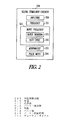
図2は、種々の実施態様に従った、神経刺激器を示し、かつ神経刺激治療を調整するように、調整できる種々の神経刺激パラメータを更に示す。種々の実施態様によれば、神経刺激器209は、神経刺激電極又はトランスデューサに送られる以下のパルス特徴:刺激パルスの振幅210、刺激パルスの周波数211、パルスのバースト周波数212、パルスの波形態213及びパルス幅214のいずれか、又はそれらの2つ以上のいかなる組み合わせも設定又は調整するためのモジュールを含む。神経刺激電極の例には、神経カフと、神経標的を経血管刺激する血管内供給される電極とを含む。刺激トランスデューサの例には、神経標的を刺激するために使用される超音波、磁気及び光トランスデューサを含む。示したバースト周波数パルス特徴212は、バースト周波数パルス特徴の一部として調整できるか、又は別個に調整できるバースト持続時間215と、デューティ・サイクル216とを含む。例えば、バースト周波数は、毎分バースト数を参照できる。これらのバーストの各々は、バースト持続時間(刺激のバーストが提供される時間量)と、デューティ・サイクル(刺激が提供される時間の、時間全体に対する比)を有する。従って、限定でなく例として、6つのバーストを1分間の刺激時間(バースト持続時間)中に送りうる。バーストは、それおぞれの長さ(パルス幅)が5秒であり、かつバースト間の期間が5秒である。この実施例では、バースト周波数は毎分6バーストであり、刺激時間すなわちバースト持続時間は、60秒であり、かつ、デューティ・サイクルは、50%である((6バースト×5秒/バースト)/60秒)。その上、1つ以上のバーストの持続時間は、いかなる定常バースト周波数も参照せずに、調整できる。例えば、所定バースト持続時間の単一の刺激バースト又は所定パルス幅のバーストパターン、及びバーストタイミングは、感知信号に応答して提供できる。更に、デューティ・サイクルは、バーストを定常バースト周波数で送る必要なしに、バースト数を調整することによって、かつ/又は1つ以上のバースト期間を調整することによって、調整できる。波形形態の例には、方形波、三角波、正弦波、及び自然発生的な圧反射刺激を示すような、白色雑音を模倣するための所望の調和成分を有する波が含まれる。
FIG. 2 illustrates a neural stimulator according to various embodiments and further illustrates various neural stimulation parameters that can be adjusted to adjust the neural stimulation therapy. According to various embodiments, the
図3は、種々の実施態様に従った、抗頻脈治療を示す。317で、頻脈が検出されるかが決定される。頻脈が検出されるならば、プロセスは318に進み、そこでVT治療選択のための複合特徴セットRが形成される。例えば、VT特性は、電気記録図(EGM)及び血行力学的センサから抽出できる。複合特徴は、頻脈治療にマッピングされる。それ故に、複合特徴セットRに基づき、プロセスは、進み、319でATP治療を提供し、320でショック治療を提供し、又は321で神経刺激を送る。示したプロセスにおいて、例えば、322で複合特徴セットRが、ATP治療の即時適用の基準を満たすかが決定でき、かつ満たすならば323でATP治療を提供する。満たさないならば、324で複合特徴セットRが、ショックを即時に適用する基準を満たすかが決定でき、かつ満たすならば325でショック治療を提供する。満たさないならば、326でこの頻脈発症のための最大数の神経刺激の試みが、なされたかが決定でき、かつなされたならば、ショックが325で送られ得る。なされないならば、神経刺激が、327で適用される。当業者は、この開示を読み、かつ理解すれば、特徴セットがATP基準の前にショック基準を満たすか決定されるように、これらの決定の順序が、変化できることを理解するであろう。その上、当業者は、ある種の基準が満たされる時、323でATPを直接に提供し、他の基準が満たされる時、325でショックを直接に送り、かつ更に他の基準が満たされる時、321で神経刺激を送るために、マッピング機能が使用できることを理解するであろう。328で、頻脈発症が継続しているかが、決定される。VTが329で検出されるならば、プロセスは、318に戻り、検出VTの複合特徴セット特性を形成する。VTが329で検出されないならば、治療が、成功であり、かつVT発症が終結したことが決定される。 FIG. 3 illustrates anti-tachycardia therapy according to various embodiments. At 317, it is determined whether a tachycardia is detected. If a tachycardia is detected, the process proceeds to 318 where a composite feature set R for VT treatment selection is formed. For example, VT characteristics can be extracted from electrograms (EGM) and hemodynamic sensors. Composite features are mapped to tachycardia therapy. Therefore, based on the composite feature set R, the process proceeds, providing ATP therapy at 319, providing shock therapy at 320, or sending neural stimulation at 321. In the illustrated process, for example, at 322, it can be determined whether the composite feature set R meets the criteria for immediate application of ATP therapy, and if so, at 323 provides ATP therapy. If not, it can be determined at 324 whether the composite feature set R meets the criteria for immediate shock application and if so, at 325 shock therapy is provided. If not, at 326 it can be determined whether the maximum number of neural stimulation attempts for the onset of tachycardia have been made and if so, a shock can be sent at 325. If not, neural stimulation is applied at 327. Those skilled in the art will understand that upon reading and understanding this disclosure, the order of these decisions can be varied so that the feature set is determined to meet the shock criteria before the ATP criteria. Moreover, those skilled in the art will provide ATP directly at 323 when certain criteria are met, deliver shocks directly at 325 when other criteria are met, and when other criteria are met 321, it will be appreciated that a mapping function can be used to send the neural stimulation. At 328, it is determined whether the onset of tachycardia continues. If a VT is detected at 329, the process returns to 318 to form a composite feature set characteristic of the detected VT. If VT is not detected at 329, it is determined that the treatment is successful and that VT onset has ended.
装置の実施態様
図4は、種々の実施態様に従った、埋め込み型医療装置を示す。示した装置430は、例えばEGM又は血行力学的センサのような、センサ入力431を含む。センサは、リード又は無線チャネルを介してセンサ入力に接続できる。センサは、頻脈性不整脈が検出される時期を決定するためにも使用できる。特徴抽出器432は、センサ入力431に接続され、頻脈性不整脈に関連した多数の感知特徴を抽出する。限定でなく、例として、特徴抽出器は、心拍数433と、心拍数安定性434と、形態異常435と、圧力変化436とを検出できる。特徴抽出器に接続された特徴セット発生器437は、抽出された特徴から、複合特徴セットを形成する。コンパレータ438は、発生した特徴セットを特徴セット基準439と比較する。示した特徴セット基準には、ショックを適用する基準440と、ATPを適用する基準441と、ATP治療のために頻脈性不整脈を調整するための、神経刺激を適用する基準442とを含む。コントローラ443は、コンパレータ438から信号を受信し、かつ発生した特徴セットの、特徴セット基準との比較に基づき、ショック発生器444、ATP発生器445、及び/又はNS発生器446を適切に制御する。ショック発生器444、ATP発生器445、及びNS発生器446は、ショック治療と、ATP治療と、神経刺激治療とを提供するために使用する刺激提供システム447に接続される。これらの治療の幾つかは、種々の実施態様により共通の電極を使用できる。幾つかの実施態様において、これらの治療は、別個の電極を使用する。
Device Embodiments FIG. 4 illustrates an implantable medical device according to various embodiments. The illustrated
図5は、種々の実施態様に従った、ショック治療、抗頻脈ペーシング(ATP)治療、又は不整脈を予め調整するための神経刺激によるATP治療を提供するかを決定する際に使用する基準を示す。種々の実施態様によれば、VTが検出される時(例えば、ある心拍数ゾーン内の持続的律動)、N次元特徴セットRが構築され、ここでR={R1,R2,...,RN}である。セットR中の各要素Riは、EGMのような電気信号か、加速度計、圧力センサ、インピーダンスセンサ等のような1つ以上のセンサによって記録された信号から抽出された特徴である。これらのセンサ信号からの特徴は、VT中の血行力学的安定性の測定又は推定である。一実施態様において、セットRは、以下のように構築される:R={R1,R2,R3,R4}(式中、R1は、装置内の心拍数感知チャネルを使用して測定された心房又は心室心拍数であり、R2は、最新のAA又はRR間隔の分散として算出される心拍数の安定性であり、R3は、最新のM拍動形態の試料エントロピーとして算出された心臓内形態異常であり、かつR4は、専用の埋め込み型肺動脈圧センサを使用することによって測定された(例えば、正常洞制御中の)正常状態からの心室内圧力差である)。 FIG. 5 illustrates the criteria used in determining whether to provide shock therapy, anti-tachycardia pacing (ATP) therapy, or neural stimulation ATP therapy to precondition arrhythmias, according to various embodiments. Show. According to various embodiments, when a VT is detected (eg, a continuous rhythm within a heart rate zone), an N-dimensional feature set R is constructed, where R = {R1, R2,. . . , RN}. Each element Ri in the set R is a feature extracted from an electrical signal such as EGM or a signal recorded by one or more sensors such as accelerometers, pressure sensors, impedance sensors, and the like. A feature from these sensor signals is a measurement or estimation of hemodynamic stability during VT. In one embodiment, the set R is constructed as follows: R = {R1, R2, R3, R4}, where R1 is the atrium measured using a heart rate sensing channel in the device. Or R2 is the stability of the heart rate calculated as the variance of the latest AA or RR interval, and R3 is the intracardiac morphological abnormality calculated as the sample entropy of the latest M beat form And R4 was measured by using a dedicated implantable pulmonary artery pressure sensor (eg, the intraventricular pressure difference from normal (eg during normal sinus control)).
幾つかの実施態様において、圧力は、例えば、経胸腔インピーダンス変動、S1及び/又はS2心音の強度変動等を測定する他のセンサを使用して間接的に推定される。R中の複合特徴は、以下の決定:「ATPを送る」、「ショックを送る」、及び「NSを送る」の1つにマッピングされる。種々の実施態様において、マッピングは、プロセッサ又はコントローラにおけるアルゴリズムセットとして実施される。種々の実施態様において、マッピングは、参照テーブルを使用して実行される。種々の実施態様において、マッピングは、論理回路によって実行される。 In some embodiments, the pressure is estimated indirectly using other sensors that measure, for example, transthoracic impedance variation, S1 and / or S2 heart sound intensity variation, and the like. The composite features in R are mapped to one of the following decisions: “Send ATP”, “Send Shock”, and “Send NS”. In various embodiments, the mapping is implemented as an algorithm set in a processor or controller. In various embodiments, the mapping is performed using a lookup table. In various embodiments, the mapping is performed by a logic circuit.
頻脈性不整脈が、著しく不安定な血行力学、非常に速い心拍数、又は心拍数及び形態の両方において非常に不安定な律動を特徴とすることを、特徴セットが示す時、ショック治療が、システムの能力内で即時又はほぼ即時に、提供される。頻脈性不整脈が、遅く、かつ血行力学的に安定した単源性VTを特徴とすることを、特徴セットが示す時、ATP治療が、システムの能力内で即時又はほぼ即時に、提供される。かかる律動は、遅く、かつ血行力学的に安定した単源性VTである。頻脈性不整脈が、中程度に高速で、不安定な律動、及び小幅な血行力学的悪化を特徴とすることを特徴セットが示す時、NS治療が適用される。神経刺激が、頻脈性不整脈を終結させることがあるが、NS治療は、改善された頻脈性不整脈が、ATP治療に修正できると分類でき、かつ対応する特徴セットがATP治療を引き起こすように、心拍数を減少させ、かつ不整脈の安定性を増加させるために、頻脈性不整脈を調整するために適用される。従って、VTは、伝統的なICD内から提供されるように、ショック治療よりもむしろATP治療が続くNS治療を予め調整することによって終結させることができる。一実施態様において、マッピングは、複合規則が、N次元特徴空間において治療決定を行うために使用される、「規則ベース」として実施される。 When the feature set indicates that tachyarrhythmia is characterized by markedly unstable hemodynamics, very fast heart rate, or a very unstable rhythm in both heart rate and morphology, shock therapy is Provided immediately or almost immediately within the capabilities of the system. When the feature set indicates that tachyarrhythmia is characterized by a slow and hemodynamically stable monogenic VT, ATP treatment is provided immediately or nearly immediately within the capabilities of the system. . Such a rhythm is a slow and hemodynamically stable unigenic VT. NS therapy is applied when the feature set indicates that tachyarrhythmia is characterized by moderately fast, unstable rhythms, and minor hemodynamic deterioration. Nerve stimulation may terminate tachyarrhythmia, but NS treatment can be classified as improved tachyarrhythmia can be modified to ATP treatment, and the corresponding feature set causes ATP treatment Applied to adjust tachyarrhythmia to reduce heart rate and increase arrhythmia stability. Thus, VT can be terminated by preconditioning NS treatment followed by ATP treatment rather than shock treatment, as provided from within traditional ICDs. In one embodiment, the mapping is implemented as a “rule base” where compound rules are used to make treatment decisions in an N-dimensional feature space.
種々の実施態様において、例えばショック治療は、以下の諸状態のいずれでも提供できる。圧力は、頻脈性不整脈が、血行力学的に非常に不安定であることを示す所定値未満であること; 心拍数は、頻脈性不整脈が極めて高い心拍数と関連することを示す所定値よりも大きいこと; 圧力は、所定の圧力範囲内であり、心拍数は、所定の心拍数範囲内であり、安定性は、閾値よりも高く、かつ、形態(モーフォロジイ)は、頻脈性不整脈が血行力学的に不安定であって速く且つ不規則な心拍数及び形態を有することを示す閾値よりも高いこと。 In various embodiments, for example, shock therapy can be provided in any of the following conditions. The pressure is less than a predetermined value indicating that the tachyarrhythmia is very hemodynamically unstable; the heart rate is a predetermined value indicating that the tachyarrhythmia is associated with a very high heart rate Pressure is within a predetermined pressure range, heart rate is within a predetermined heart rate range, stability is above a threshold, and morphology is a tachyarrhythmia Is higher than a threshold indicating that it is hemodynamically unstable and has a fast and irregular heart rate and morphology.
種々の実施態様において、例えばATP治療は、以下の状態のいずれでも提供される。心拍数は所定の範囲内であり、且つ、安定性は、頻脈が遅くかつ安定したVTであることを示す閾値よりも低いこと; 圧力は、閾値よりも高く、かつ心拍数は、血行力学的に安定し、かつ遅いVTであることを示す閾値よりも低いこと; 圧力は、閾値よりも高く、心拍数は、所定の範囲内であり、かつ安定性は、閾値未満であり、かつ形態異常は、中程度の心拍数を有する血行力学的に安定したVTを示す閾値よりも低いこと。 In various embodiments, for example, ATP treatment is provided in any of the following conditions. The heart rate is within a predetermined range, and the stability is lower than a threshold indicating that the tachycardia is slow and stable VT; the pressure is higher than the threshold, and the heart rate is hemodynamic Lower than a threshold indicating stable and slow VT; pressure is above threshold, heart rate is within a predetermined range, and stability is below threshold, and morphology Abnormality is below a threshold indicating a hemodynamically stable VT with a moderate heart rate.
種々の実施態様において、例えばNS治療は、圧力が閾値よりも高く、心拍数が所定範囲内にあり、かつ、安定性が所定範囲内(すなわち、頻脈性不整脈が、血行力学的に安定しているが、心拍数が速く、かつ不安定であることを示す所定範囲内)にある時に、提供される。 In various embodiments, for example, NS therapy is such that the pressure is above a threshold, the heart rate is within a predetermined range, and the stability is within a predetermined range (ie, tachyarrhythmia is hemodynamically stable). Provided that the heart rate is within a predetermined range indicating that it is fast and unstable.
種々の実施態様は、ショック、ATP又はNS治療を適用するかを決定するために、決定融合方法(decision fusion method)を使用する。融合エンジン機能の例は、X=f(R1,R2,...,RN)によって提供される。一実施例において、Riは、大きいRiが重度の状態を示すように定義され、かつfは、Xが全ての特徴Rの加重和であるような全てのRiの一次関数である。加重kは、危険因子である。次に、例えばショックは、Xが第1閾値よりも大きいならば提供できる。ATP治療は、Xが第2閾値未満ならば、提供でき、かつNS治療は、Xが第1及び第2閾値の間にあるならば提供できる。 Various embodiments use a decision fusion method to determine whether to apply shock, ATP or NS therapy. An example of a fusion engine function is provided by X = f (R1, R2,..., RN). In one embodiment, Ri is defined such that large Ri indicates a severe condition, and f is a linear function of all Ri such that X is a weighted sum of all features R. The weight k is a risk factor. Next, for example, a shock can be provided if X is greater than the first threshold. ATP therapy can be provided if X is below the second threshold, and NS therapy can be provided if X is between the first and second thresholds.
幾つかの実施態様において、(周波数、持続期間等のような)異なる設定を有する多数のNSプロトコルは、装置内で予めプログラムされ、かつ記憶される。一実施態様において、「NSを送る」決定がなされる時に、いずれのNSプロトコルを使用するか決定するために、心拍数変動(HRV)が、VT前及び中に監視される。標準HRVパラメータ(例えば、時間領域ではSDANN、又は周波数領域ではLF/HF比)は、交感/副交感神経平衡を記載するための数量である。心拍数不整(HRT)又は神経センサのような自律平衡又は健康を決定する他の方法が、使用できる。有意な自律神経失調は、より積極的なNS治療を必要とし得る。適切なNSプロトコルの選択は、時刻に基づくこともできる。VT発生は、概日リズムに従うので(有意に高率のVT発生及びATP失敗が午前6時から午後12時の間に起こる)、より積極的なNS治療が、このVT危険性増加の期間中に適用できる。 In some embodiments, multiple NS protocols with different settings (such as frequency, duration, etc.) are pre-programmed and stored in the device. In one embodiment, heart rate variability (HRV) is monitored before and during VT to determine which NS protocol to use when a “send NS” decision is made. Standard HRV parameters (eg, SDANN in the time domain, or LF / HF ratio in the frequency domain) are quantities that describe sympathetic / parasympathetic balance. Other methods of determining autonomic balance or health such as heart rate irregularity (HRT) or neural sensors can be used. Significant autonomic ataxia may require more aggressive NS treatment. The selection of an appropriate NS protocol can also be based on time of day. Since VT occurrence follows a circadian rhythm (significantly higher rates of VT occurrence and ATP failure occur between 6 am and 12 pm), more aggressive NS treatment is applied during this increased VT risk it can.
神経刺激は、迷走神経、迷走神経の心臓枝、心臓脂肪体、圧受容器部位、又は副交感神経系を刺激するか、交感神経系を阻害する他の神経標的に適用できる。神経刺激は、血管内供給される電極、神経カフ、サテライト電極、及び神経標的を刺激する他の公知の手段を使用して適用できる。 Neural stimulation can be applied to vagus nerves, vagus nerve heart branches, cardiac fat pads, baroreceptor sites, or other neural targets that inhibit or inhibit the sympathetic nervous system. Neural stimulation can be applied using intravascularly supplied electrodes, neural cuffs, satellite electrodes, and other known means of stimulating neural targets.
ATP治療前のNS治療の適用は、その高速で、不安定な律動、又は血行力学的悪化のために従来のICD内でショックを与えられたであろう広範囲のVTを終結させる際に有用であり得る。無痛性治療の有効性は、大いに改善でき、かつ疼痛を伴うショック治療は、減少できる。 The application of NS treatment prior to ATP treatment is useful in terminating the wide range of VT that would have been shocked within conventional ICDs due to its fast, unstable rhythm, or hemodynamic deterioration. possible. The effectiveness of analgesic treatment can be greatly improved, and painful shock treatment can be reduced.
図6は、種々の実施態様に従った、神経刺激(NS)部品649と、心律動管理(CRM)部品650とを有する埋め込み型医療装置(IMD)648を示す。示した装置は、コントローラ651と、メモリ652とを含む。種々の実施態様によれば、コントローラは、神経刺激及びCRM機能を実行するために、ハードウェア、ソフトウェア、並びにハードウェア及びソフトウェアの組み合わせを含む。例えば、本開示において論じられたプログラムされた治療応用は、メモリにおいて具体化され、かつプロセッサによって実行されるコンピュータ読み取り可能な命令として記憶されることができる。種々の実施態様によれば、コントローラは、神経刺激及びCRM機能を実行するための、メモリに埋設された命令を実行するために、プロセッサを含む。CRM機能の例には、徐脈ペーシング、ATP、除細動及び電気除細動、並びにCRTのような抗頻脈治療を含む。コントローラは、頻脈を検出するための命令を同様に実行する。示した装置は、トランシーバ653と、プログラマ又は他の外部若しくは内部装置と通信するために使用する関連した回路とを更に含む。種々の実施態様は、遠隔測定コイルを含む。
FIG. 6 shows an implantable medical device (IMD) 648 having a neural stimulation (NS)
CRM治療セクション650は、1つ以上の電極を使用して、心臓を刺激し、かつ/又は心臓信号を感知するために、コントローラの制御下で部品を含む。示したCRM治療セクションは、心臓を刺激するために電極を通して電気信号を提供するために使用するパルス発生器654を含み、かつ感知心臓信号を検出及び処理するための感知回路655を更に含む。インタフェース656は、コントローラ651及びパルス発生器654及び感知回路655間の通信に使用するために一般的に示される。3つの電極は、CRM治療を提供するための使用例として示される。しかしながら、本件発明は、特定数の電極部位に限定されない。各電極は、それ自身のパルス発生器と、感知回路とを含むことができる。しかしながら、本件発明は、そのように限定されない。パルス発生及び感知機能は、複数の電極と機能するために多重化できる。
The
NS治療セクション649は、神経刺激標的を刺激し、かつ/又は血圧及び呼吸のような、神経活動若しくは神経活動の代用物と関連するパラメータを感知するために、コントローラの制御下で、部品を含む。3つのインタフェース657が、神経刺激を提供するための使用のために示される。しかしながら、本件発明は、特定数のインタフェース、又はいかなる特定の刺激若しくは感知機能にも限定されない。パルス発生器658は、トランスデューサ、又は神経刺激標的を刺激をするために使用するトランスデューサに、電気パルスを提供するために使用される。種々の実施態様によれば、パルス発生器は、刺激パルスの振幅、刺激パルスの周波数、パルスのバースト周波数、及び方形波、三角波、正弦波、及び白色雑音又は他の信号を模倣するための所望の調和成分を有する波のようなパルスの形態を設定し、かつ幾つかの実施態様では変更する回路を含む。感知回路659は、神経活動、血圧、呼吸等のセンサのような、センサからの信号を検出及び処理するために使用される。インタフェース657は、一般的にコントローラ651及びパルス発生器658及び感知回路659間の通信に使用するために示される。各インタフェースは、例えば別個のリードを制御するために使用できる。NS治療セクションの種々の実施態様は、迷走神経のような神経標的を刺激するパルス発生器のみを含む。
図7は、種々の実施態様に従った、マイクロプロセッサに基づく埋め込み型装置の実施態様の系統図を示す。装置のコントローラは、双方向データバスを介してメモリ761と通信するマイクロプロセッサ760である。コントローラは、状態機械タイプの設計を使用する、他のタイプの論理回路(例えば、個別部品又はプログラマブルロジックアレイ)によって実装できるが、マイクロプロセッサに基づくシステムが、好ましい。本明細書で使用されるように、用語「回路」は、個別論理回路か、マイクロプロセッサのプログラミングを指すと解釈されるべきである。図中に、リング電極762A−C及びチップ電極763A−Cを有する双極リードと、感知増幅器764A−Cと、パルス発生器765A−Cと、チャネルインタフェース766A−Cとを含む、「A」から「C」と指定される感知及びペーシングチャネルの3つの例が、示される。各チャネルは、このようにして電極に接続されるパルス発生器で構成されるペーシングチャネルと、電極に接続される感知増幅器で構成される感知チャネルとを含む。チャネルインタフェース766A−Cは、マイクロプロセッサ760と双方向で通信し、かつ各インタフェースは、ペーシングパルスを出力し、ペーシングパルスの振幅を変え、かつ感知増幅器の利得及び閾値を調整するために、マイクロプロセッサによって書き込めるレジスタ及び感知増幅器からの感知信号入力をディジタル化するアナログ−ディジタル変換器を含むことがある。ペースメーカの感知回路は、特定のチャネルによって発生した電気記録図信号(すなわち心臓電気活性を表す電極によって感知された電圧)が、規定の検出閾値を超える時、心腔感知、心房感知又は心室感知を検出する。特定のペーシングモードで使用されるペーシングアルゴリズムは、ペーシングを引き起こすか、又は阻害するためにかかる感知を用いる。内因性心房及び/又は心室拍数は、それぞれ心房及び心室感知の間の時間間隔を測定することによって測定でき、かつ心房及び心室頻脈性不整脈を検出するために使用できる。
FIG. 7 shows a system diagram of an embodiment of a microprocessor-based implantable device according to various embodiments. The controller of the device is a
各双極リードの電極は、リード内の導体を介して、マイクロプロセッサによって制御されるスイッチング回路網767に接続される。スイッチング回路網は、内因性心臓活動を検出するために感知増幅器の入力に、かつペーシングパルスを送るためにパルス発生器の出力に、電極を切り替えるために使用される。スイッチング回路網は、装置が、リードのリング及びチップ電極の両方を使用する双極モードで、又はリードの電極の一方のみを使用する単極モードで感知又はペーシングすることも可能にし、装置ハウジング(缶)768、又は他のリード上の他の電極が、接地電極の役目を果たす。ショックパルス発生器769は、ショックを与えられる頻脈性不整脈を検出すると、心房又は心室に一対のショック電極770及び771を介して除細動ショックを送るコントローラにもインタフェースで接続される。
The electrode of each bipolar lead is connected via a conductor in the lead to a
コントローラは、抗頻脈ペーシングが提供される方法を定義する複数の選択可能なATPペーシングプロトコルによってプログラムできる。マイクロプロセッサに基づく装置において、ペーシングパルスの出力は、種々のパラメータによって定義されるような、選択されたペーシングプロトコルを実施するペーシングルーチンによって制御できる。メモリ内に記憶されたデータ構造は、利用可能なペーシングプロトコルの各々を定義するパラメータセットを含む。様々なプロトコルが、心拍数及び/又は脱分極パターンに関して異なり得る、特定の頻脈性不整脈を終結させることにおいて、他のものよりも成功する傾向がある。この理由のために、現代の心律動管理装置は、治療を提供するために多数の異なるATPプロトコルを使用することが可能である。 The controller can be programmed with a plurality of selectable ATP pacing protocols that define how anti-tachycardia pacing is provided. In microprocessor-based devices, the output of pacing pulses can be controlled by a pacing routine that implements a selected pacing protocol, as defined by various parameters. The data structure stored in the memory includes a set of parameters that define each of the available pacing protocols. Various protocols tend to be more successful than others in terminating certain tachyarrhythmias, which can differ in terms of heart rate and / or depolarization pattern. For this reason, modern cardiac rhythm management devices can use many different ATP protocols to provide therapy.
チャネルD及びEと識別される、神経刺激チャネルは、副交感神経刺激及び/又は交感神経阻害を提供するために装置に組み込まれ、そこで一方のチャネルは、第1電極772Dと、第2電極773Dと、パルス発生器774Dと、チャネルインタフェース775Dとを有する双極リードを含み、かつ他方のチャネルは、第1電極772Eと、第2電極773Eと、パルス発生器774Eと、チャネルインタフェース775Eとを有する双極リードを含む。他の実施態様は、単極リードを使用でき、その場合に神経刺激パルスが、缶又は他の電極に関係付けられる。各チャネルのパルス発生器は、振幅、周波数、デューティ・サイクル等に関してコントローラによって異なっても良い、一連の神経刺激パルスを出力する。この実施態様において、神経刺激チャネルの各々は、適切な神経標的の近くに、例えば、交感神経阻害チャネルの場合に圧受容器の近く、又は副交感神経刺激チャネルの場合に副交感神経の近くに、血管内配置できるリードを使用する。他のタイプのリード及び/又は電極も、用いることができる。神経カフ電極は、神経刺激を提供するために、血管内配置電極の代わりに使用でき、ここで電極は、副交感神経刺激を提供するために、例えば頸部迷走神経束の周りに、又は交感神経阻害を提供するために、大動脈又は頸動脈洞神経の周りに設置できる。肺動脈内又はその近くの圧受容器も刺激できる。もう1つの実施態様において、神経刺激電極のリードは、無線リンクによって置き換えられ、かつ副交感神経刺激及び/又は交感神経阻害を提供する電極は、サテライト装置に組み込まれる。適用される神経刺激は、頻脈性不整脈を終結させ得るが、神経刺激は、頻脈を、ATPによって首尾良く終結させられる、高い可能性を有する律動に変化させることが期待される。
A neural stimulation channel, identified as channels D and E, is incorporated into the device to provide parasympathetic stimulation and / or sympathetic inhibition, where one channel is a first electrode 772D, a second electrode 773D, and A bipolar lead having a
図は、外部装置と通信するために使用できる、マイクロプロセッサに接続された遠隔測定インタフェース776を示す。示したマイクロプロセッサ760は、神経刺激治療ルーチン及び心筋刺激ルーチンを実行することが可能である。NS治療ルーチンの例には、頻脈性不整脈用のATP前NS治療を含む。心筋治療ルーチンの例には、徐脈ペーシング治療、電気除細動又は除細動治療のような抗頻脈ショック治療、抗頻脈ペーシング治療、及び心臓再同期治療を含む。
The figure shows a
システムの実施態様
図8は、種々の実施態様に従った、埋め込み型医療装置(IMD)878と、外部システム又は装置879とを含むシステム877を示す。IMD878の種々の実施態様は、NS及びCRM機能の組み合わせを含む。IMDは、生物剤と、医薬品も提供できる。外部システム879及びIMD878は、データ及び命令を無線通信することが可能である。種々の実施態様において、例えば外部システム及びIMDは、データ及び命令を無線通信するために、遠隔測定コイルを使用する。従って、プログラマが、IMDによって提供されるプログラムされた治療を調整するために使用でき、かつIMDは、例えば、無線遠隔測定を使用してプログラマに、(電池及びリード抵抗のような)装置データと、(感知及び刺激データのような)治療データとを報告できる。種々の実施態様によれば、IMDは、抗頻脈治療を提供するために神経標的及び心筋を刺激する。
System Embodiments FIG. 8 shows a
外部システムは、医師若しくは他の介護者又は患者のような利用者が、IMDの操作を制御し、かつIMDによって獲得された情報を得ることを可能にする。一実施態様において、外部システムは、IMDと遠隔測定リンクを介して双方向に通信するプログラマを含む。もう1つの実施態様において、外部システムは、電気通信網を通して遠隔装置と通信する外部装置を含む患者管理システムである。外部装置は、IMDの近傍にあり、かつIMDと遠隔測定リンクを介して双方向に通信する。遠隔装置は、利用者が離れた位置から患者を監視し、かつ処置することを可能にする。患者監視システムは、更に後述する。 The external system allows a user such as a physician or other caregiver or patient to control the operation of the IMD and obtain information obtained by the IMD. In one embodiment, the external system includes a programmer that communicates bidirectionally with the IMD via a telemetry link. In another embodiment, the external system is a patient management system that includes an external device that communicates with a remote device through a telecommunications network. The external device is in the vicinity of the IMD and communicates bidirectionally with the IMD via the telemetry link. The remote device allows the user to monitor and treat the patient from a remote location. The patient monitoring system is further described below.
遠隔測定リンクは、埋め込み型医療装置から外部システムへのデータ伝送を提供する。このことは、例えばIMDによって獲得されたリアルタイム生理的データを伝送することと、IMDによって獲得され、かつ記憶された生理的データを抽出することと、埋め込み型医療装置に記憶された治療履歴データを抽出することと、IMDの作動状態(例えば、電池状態及びリードインピーダンス)を示すデータを抽出することとを含む。遠隔測定リンクは、外部システムからIMDへのデータ伝送も提供する。このことは、例えば生理的データを獲得するためにIMDをプログラミングすることと、(装置作動状態のような)少なくとも1つの自己診断テストを実行するためにIMDをプログラミングすることと、少なくとも1つの治療を提供するために、IMDをプログラミングすることとを含む。 The telemetry link provides data transmission from the implantable medical device to an external system. This includes, for example, transmitting real-time physiological data acquired by the IMD, extracting physiological data acquired and stored by the IMD, and treating history data stored in the implantable medical device. Extracting, and extracting data indicating the operating state of the IMD (eg, battery state and lead impedance). The telemetry link also provides data transmission from the external system to the IMD. This includes, for example, programming the IMD to acquire physiological data, programming the IMD to perform at least one self-test (such as device operating status), and at least one therapy Programming the IMD to provide:
図9は、種々の実施態様に従った、外部装置979と、埋め込み型神経刺激(NS)装置980と、埋め込み型心律動管理(CRM)装置981とを含むシステム977を示す。種々の形態は、NS装置及びCRM装置又は他の心臓刺激器の間で通信する方法を含む。種々の実施態様において、この通信は、他の装置から受信したデータに基づき、装置980又は981の一方がより適切な治療(すなわちより適切なNS治療又はCRM治療)を提供することを可能にする。幾つかの実施態様は、オンデマンド通信を提供する。種々の実施態様において、この通信は、装置の各々が、他の装置から受信したデータに基づき、より適切な治療(すなわち、より適切なNS治療及びCRM治療)を提供することを可能にする。示したNS装置及びCRM装置は、互いに無線通信することが可能であり、かつ外部システムは、NS及びCRM装置の少なくとも一方と無線通信することが可能である。例えば、種々の実施態様は、互いにデータ及び命令を無線通信するために、遠隔測定コイルを使用する。他の実施態様において、データ及び/又はエネルギーの通信は、超音波手段による。NS及びCRM装置の間に無線通信を提供するよりもむしろ、種々の実施態様は、NS装置及びCRM装置間の通信に使用するため静脈内供給されるリードのような、通信ケーブル又はワイヤを提供する。幾つかの実施態様において、外部システムは、NS及びCRM装置間の通信ブリッジの役目を果たす。
FIG. 9 illustrates a
図10は、限定でなく、例として、種々の実施態様に従った、リード1083が心臓にCRM治療を提供するために位置決めされ、かつリード1084が迷走神経を刺激するために位置決めされる、患者の胸部に皮下又は筋肉下に設置されたIMD1082を示す。リード1083は、ATP及び/又はショック治療を提供するために使用できる。種々の実施態様によれば、リード1083は、所望の心臓ペーシング治療を提供するために、心臓内又はそれに近接して位置決めされる。幾つかの実施態様において、リード1083は、所望のCRT治療を提供するために、心臓内又はそれに近接して位置決めされる。幾つかの実施態様は、リードが、心臓に対し、ペーシング、除細動及びCRT治療の少なくとも2つの組み合わせを提供できるようにする位置に、設置する。種々の実施態様によれば、神経刺激リード1084は、神経標的に皮下で貫通され、かつ神経標的を刺激するために神経カフ電極を有することができる。幾つかのリードの実施態様は、神経標的に近接した血管に血管内供給され、かつ神経標的を経血管刺激するために血管内でトランスデューサを使用する。例えば、幾つかの実施態様は、内頸静脈内に位置決めされる電極を使用して迷走神経を刺激する。
FIG. 10 illustrates, by way of example and not limitation, a patient with lead 1083 positioned to provide CRM therapy to the heart and lead 1084 positioned to stimulate the vagus nerve, according to various embodiments. Figure 2 shows an
図11は、種々の実施態様に従った、リード1183が心臓にCRM治療を提供するために位置決めされ、かつサテライトトランスデューサ1184が、心筋調整治療の一環として、少なくとも1つの副交感神経標的を刺激するために位置決めされる、IMD182を示す。サテライトトランスデューサは、無線リンクを介して、衛星に対する惑星の役目を果たす、IMDに接続される。刺激及び通信は、無線リンクを通して実行できる。無線リンクの例には、RFリンク及び超音波リンクを含む。示さないが、幾つかの実施態様は、無線リンクを使用して心筋刺激を実行する。サテライトトランスデューサの例には、皮下トランスデューサ、神経カフトランスデューサ及び血管内トランスデューサを含む。
FIG. 11 illustrates that lead 1183 is positioned to provide CRM therapy to the heart and
図12は、外部システム1285の実施態様を示すブロック図である。外部システムは、幾つかの実施態様においてプログラマを含む。図12に示した実施態様において、外部システムは、患者管理システムを含む。示すように、外部システム1285は、外部装置1286と、電気通信網1287と、遠隔装置1288とを含む患者管理システムである。外部装置1286は、IMDの近傍に設置され、かつIMDと通信するために外部遠隔測定システム1289を含む。遠隔装置1288は、1つ以上の遠隔位置にあり、かつ通信網1287を通して外部装置1286と通信し、このようにして医師又は他の介護者が離れた位置から患者を監視及び処置することを可能にし、かつ/又は1つ以上の離れた位置からの種々の処置情報源へのアクセスを可能にする。示した遠隔装置1288は、ユーザインタフェース1290を含む。
FIG. 12 is a block diagram illustrating an embodiment of the
当業者は、本明細書に示され、かつ記載されたモジュール及び他の回路が、ソフトウェア、ハードウェア、並びにソフトウェア及びハードウェアの組み合わせを使用して実施できることを理解するであろう。このようにして、用語モジュールは、ソフトウェアの実装、ハードウェアの実装、並びにソフトウェア及びハードウェアの実装を包含することが意図される。 Those skilled in the art will appreciate that the modules and other circuits shown and described herein can be implemented using software, hardware, and combinations of software and hardware. As such, the term module is intended to encompass software implementations, hardware implementations, and software and hardware implementations.
本開示に示した方法は、本願主題の範囲内の他の方法を除くことが意図されない。当業者は、本開示を読み、かつ理解すれば、本願主題の範囲内の他の方法を理解するであろう。上記実施態様、及び示した実施態様の部分は、必ずしも相互に排他的でない。これらの実施態様、又はその部分は、組み合わせることができる。種々の実施態様において、以上で提供された方法は、プロセッサによって行われる時に、プロセッサにそれぞれの方法を実行させる、命令シーケンスを表す搬送波又は伝搬信号において具体化されるコンピュータデータ信号として実施される。種々の実施態様において、以上に提供された方法は、プロセッサがそれぞれの方法を実行することを命令できるコンピュータアクセス可能な媒体に含まれる1組の命令として実施される。種々の実施態様において、媒体は、磁気媒体、電子媒体又は光学媒体である。 The methods presented in this disclosure are not intended to exclude other methods within the scope of the present subject matter. Those skilled in the art will understand other methods within the scope of the present subject matter upon reading and understanding the present disclosure. The above embodiments, and the portions of the embodiments shown, are not necessarily mutually exclusive. These embodiments, or portions thereof, can be combined. In various embodiments, the method provided above is implemented as a computer data signal embodied in a carrier wave or propagation signal representing a sequence of instructions that, when performed by the processor, causes the processor to perform the respective method. In various embodiments, the methods provided above are implemented as a set of instructions contained in a computer-accessible medium that can instruct a processor to perform each method. In various embodiments, the medium is a magnetic medium, an electronic medium, or an optical medium.
具体的な実施態様が、本明細書に示され、かつ記載されたが、同じ目的を達成するために計算されるいかなる配列も、示した具体的な実施態様の代わりに用いられることが、当業者によって認められるであろう。本出願は、本要旨の適応例及び変形例をカバーすることが意図される。上記の記述は、例示的であり、かつ限定的でないことが意図されることを理解すべきである。上記実施態様の組み合わせ、並びに他の実施態様における上記実施態様の一部の組み合わせは、上記記述を検討すれば、当業者にとって明らかであろう。本要旨の範囲は、添付の請求項を、かかる請求項が権利を与えられる同等物の全範囲と共に参照して、決定されるべきである。 Although specific embodiments are shown and described herein, it should be understood that any sequence calculated to achieve the same purpose may be used in place of the specific embodiments shown. Will be recognized by the vendor. This application is intended to cover adaptations and variations of the present subject matter. It should be understood that the above description is intended to be illustrative and not limiting. Combinations of the above embodiments, as well as some combinations of the above embodiments in other embodiments, will be apparent to those of skill in the art upon reviewing the above description. The scope of the present subject matter should be determined with reference to the appended claims, along with the full scope of equivalents to which such claims are entitled.
431 センサ入力
432 特徴抽出器
437 特徴セット発生器
443 コントローラ
444 ショック発生器
445 ATP発生器
446 NS発生器
447 刺激提供システム
651 コントローラ
654 パルス発生器
431
Claims (14)
前記頻脈性不整脈と関連した前記少なくとも1つの感知信号から少なくとも2つの特徴を抽出するように構成された特徴セット抽出器と、
前記特徴セット抽出器によって抽出された前記少なくとも2つの特徴を使用して特徴セットを形成するように構成された特徴セット発生器と、
抗頻脈ペーシング(ATP)治療及び神経刺激治療を選択的に適用するための使用に適した少なくとも1つの発生器と、
心室頻脈(VT)を検出するように構成され、そして前記特徴セット発生器を用いて前記特徴セットを構築することにより検出されたVTに応答するコントローラにして、前記特徴セットの特徴を、神経刺激(NS)を送達するための決定を含むいくつかの決定の1つにマッピングし、前記特徴セットが、前記検出されたVTを改変するためにNS治療を適用する基準に対応するときに前記NS治療を開始し、前記検出されたVTがATP治療に更に適するように改変し、前記基準が、中程度に高速、不安定な律動、および小幅な血行力学的悪化を含み、かつ前記コントローラが、改変されたVTを終結させるために前記ATP治療を開始するように構成されたコントローラと
を備えて成るシステム。At least one sensor input configured to receive at least one sensing signal associated with a tachyarrhythmia;
A feature set extractor configured to extract at least two features from the at least one sense signal associated with the tachyarrhythmia;
A feature set generator configured to form a feature set using the at least two features extracted by the feature set extractor;
At least one generator suitable for use to selectively apply anti-tachycardia pacing (ATP) therapy and neural stimulation therapy;
A controller configured to detect ventricular tachycardia (VT) and responsive to the detected VT by constructing the feature set using the feature set generator , when mapping to one of several decisions including a decision for delivering stimulation (NS), the feature set corresponds to the criteria for applying the NS therapy the detected VT to break varying start the pre Symbol NS therapy, the detected VT is modified as further suitable for ATP therapy includes the criteria, fast moderately unstable rhythm, and modest hemodynamic deterioration, and the controller, comprising a controller configured to initiate the ATP therapy to terminate the modified variable has been VT system.
Applications Claiming Priority (3)
| Application Number | Priority Date | Filing Date | Title |
|---|---|---|---|
| US11/382,120 | 2006-05-08 | ||
| US11/382,120 US8255049B2 (en) | 2006-05-08 | 2006-05-08 | Method and device for providing anti-tachyarrhythmia therapy |
| PCT/US2007/066741 WO2007133877A2 (en) | 2006-05-08 | 2007-04-17 | System to improve atp therapy using neurostimulation |
Publications (3)
| Publication Number | Publication Date |
|---|---|
| JP2009536558A JP2009536558A (en) | 2009-10-15 |
| JP2009536558A5 JP2009536558A5 (en) | 2010-04-02 |
| JP5016669B2 true JP5016669B2 (en) | 2012-09-05 |
Family
ID=38662109
Family Applications (1)
| Application Number | Title | Priority Date | Filing Date |
|---|---|---|---|
| JP2009509919A Expired - Fee Related JP5016669B2 (en) | 2006-05-08 | 2007-04-17 | System for improving ATP therapy using neural stimulation |
Country Status (4)
| Country | Link |
|---|---|
| US (2) | US8255049B2 (en) |
| EP (1) | EP2021075B1 (en) |
| JP (1) | JP5016669B2 (en) |
| WO (1) | WO2007133877A2 (en) |
Families Citing this family (45)
| Publication number | Priority date | Publication date | Assignee | Title |
|---|---|---|---|---|
| KR101114585B1 (en) * | 2004-02-05 | 2012-03-14 | 이데미쓰 고산 가부시키가이샤 | Adamantane derivatives and process for producing the same |
| US8055340B2 (en) * | 2005-05-05 | 2011-11-08 | Cardiac Pacemakers, Inc. | Method and device for comprehensive anti-tachyarrhythmia therapy |
| US8255049B2 (en) | 2006-05-08 | 2012-08-28 | Cardiac Pacemakers, Inc. | Method and device for providing anti-tachyarrhythmia therapy |
| US8983598B2 (en) * | 2006-10-04 | 2015-03-17 | Cardiac Pacemakers, Inc. | System for neurally-mediated anti-arrhythmic therapy |
| US8706212B2 (en) * | 2006-12-13 | 2014-04-22 | Cardiac Pacemakers, Inc. | Neural stimulation systems, devices and methods |
| US8437849B2 (en) * | 2007-01-30 | 2013-05-07 | Cardiac Pacemakers, Inc. | Method and apparatus for atrial pacing during tachyarrhythmia |
| US8233982B2 (en) | 2007-02-21 | 2012-07-31 | Cardiac Pacemakers, Inc. | Systems and methods for treating supraventricular arrhythmias |
| US20080281372A1 (en) * | 2007-05-09 | 2008-11-13 | Cardiac Pacemakers, Inc. | Neural stimulation system analyzer |
| US8170669B2 (en) * | 2007-10-10 | 2012-05-01 | Cardiac Pacemakers, Inc. | Method and apparatus for concurrent atrio-ventricular anti-tachycardia pacing |
| WO2009114096A1 (en) | 2008-03-13 | 2009-09-17 | Cardiac Pacemakers, Inc. | Systems and devices for modulating autonomic tone |
| JP5292416B2 (en) * | 2008-03-13 | 2013-09-18 | カーディアック ペースメイカーズ, インコーポレイテッド | Autonomic balance monitoring to control intermittent therapy |
| US8706220B2 (en) * | 2008-04-09 | 2014-04-22 | Medtronic, Inc. | Method and apparatus for detecting and treating tachyarrhythmias incorporating diagnostic/therapeutic pacing techniques |
| US8244350B2 (en) * | 2008-08-05 | 2012-08-14 | Cardiac Pacemakers, Inc. | Neural stimulation for arrhythmia recognition and therapy |
| US9597505B2 (en) | 2008-10-31 | 2017-03-21 | Medtronic, Inc. | Implantable medical device crosstalk evaluation and mitigation |
| US8611996B2 (en) * | 2008-10-31 | 2013-12-17 | Medtronic, Inc. | Implantable medical device crosstalk evaluation and mitigation |
| US8260412B2 (en) * | 2008-10-31 | 2012-09-04 | Medtronic, Inc. | Implantable medical device crosstalk evaluation and mitigation |
| WO2010051499A1 (en) | 2008-10-31 | 2010-05-06 | Medtronic, Inc. | Therapy system including cardiac rhythm therapy and neurostimulation capabilities |
| US8005539B2 (en) * | 2008-10-31 | 2011-08-23 | Medtronic, Inc. | Implantable medical device crosstalk evaluation and mitigation |
| US8612020B2 (en) * | 2008-10-31 | 2013-12-17 | Medtronic, Inc. | Implantable therapeutic nerve stimulator |
| US8406893B2 (en) * | 2008-10-31 | 2013-03-26 | Medtronic, Inc. | Interference mitigation for implantable device recharging |
| US8452394B2 (en) * | 2008-10-31 | 2013-05-28 | Medtronic, Inc. | Implantable medical device crosstalk evaluation and mitigation |
| US8265771B2 (en) * | 2008-10-31 | 2012-09-11 | Medtronic, Inc. | Interference mitigation for implantable device recharging |
| US20100114209A1 (en) * | 2008-10-31 | 2010-05-06 | Medtronic, Inc. | Communication between implantable medical devices |
| US8688210B2 (en) | 2008-10-31 | 2014-04-01 | Medtronic, Inc. | Implantable medical device crosstalk evaluation and mitigation |
| US8301263B2 (en) * | 2008-10-31 | 2012-10-30 | Medtronic, Inc. | Therapy module crosstalk mitigation |
| US8774918B2 (en) | 2008-10-31 | 2014-07-08 | Medtronic, Inc. | Implantable medical device crosstalk evaluation and mitigation |
| US9775987B2 (en) * | 2008-10-31 | 2017-10-03 | Medtronic, Inc. | Implantable medical device crosstalk evaluation and mitigation |
| US9289613B2 (en) | 2008-10-31 | 2016-03-22 | Medtronic, Inc. | Interdevice impedance |
| US8532779B2 (en) * | 2008-10-31 | 2013-09-10 | Medtronic, Inc. | Implantable medical device crosstalk evaluation and mitigation |
| US8249708B2 (en) * | 2008-10-31 | 2012-08-21 | Medtronic, Inc. | Implantable medical device crosstalk evaluation and mitigation |
| US9814886B2 (en) | 2009-01-30 | 2017-11-14 | Medtronic, Inc. | Detecting and treating electromechanical dissociation of the heart |
| US8285371B2 (en) * | 2009-04-22 | 2012-10-09 | Cardiac Pacemakers, Inc. | Dynamic selection of algorithms for arrhythmia detection |
| WO2011103071A1 (en) * | 2010-02-17 | 2011-08-25 | Cardiac Pacemakers, Inc. | Hemodynamic stability detection during arrhythmia using respiration sensor |
| US8903490B2 (en) * | 2010-03-03 | 2014-12-02 | Cardiac Pacemakers, Inc. | Methods and systems for recognizing arrhythmias using neural stimulation |
| US8639327B2 (en) | 2010-04-29 | 2014-01-28 | Medtronic, Inc. | Nerve signal differentiation in cardiac therapy |
| US8888699B2 (en) | 2010-04-29 | 2014-11-18 | Medtronic, Inc. | Therapy using perturbation and effect of physiological systems |
| JP5608812B2 (en) | 2010-05-07 | 2014-10-15 | カーディアック ペースメイカーズ, インコーポレイテッド | Output circuit for both electrical stimulation and neuromodulation |
| US8706223B2 (en) | 2011-01-19 | 2014-04-22 | Medtronic, Inc. | Preventative vagal stimulation |
| US8781582B2 (en) * | 2011-01-19 | 2014-07-15 | Medtronic, Inc. | Vagal stimulation |
| US8725259B2 (en) | 2011-01-19 | 2014-05-13 | Medtronic, Inc. | Vagal stimulation |
| US8718763B2 (en) | 2011-01-19 | 2014-05-06 | Medtronic, Inc. | Vagal stimulation |
| US8880170B2 (en) | 2011-11-29 | 2014-11-04 | Cardiac Pacemakers, Inc. | Autonomic modulation using peripheral nerve field stimulation |
| US8600500B1 (en) | 2012-12-11 | 2013-12-03 | Pacesetter, Inc. | Method and system to provide neural stimulation therapy to assist anti-tachycardia pacing therapy |
| US10765875B2 (en) | 2017-05-04 | 2020-09-08 | University Of Utah Research Foundation | Implantable cardiac devices and methods for delivering low energy, pain-free defibrillation signals for ventricular arrhythmias |
| WO2022261001A1 (en) * | 2021-06-07 | 2022-12-15 | Boston Scientific Neuromodulation Corporation | Stimulation systems with user-specified routines and methods of making and using |
Family Cites Families (59)
| Publication number | Priority date | Publication date | Assignee | Title |
|---|---|---|---|---|
| US5405363A (en) | 1991-03-15 | 1995-04-11 | Angelon Corporation | Implantable cardioverter defibrillator having a smaller displacement volume |
| US5203326A (en) | 1991-12-18 | 1993-04-20 | Telectronics Pacing Systems, Inc. | Antiarrhythmia pacer using antiarrhythmia pacing and autonomic nerve stimulation therapy |
| US5697953A (en) | 1993-03-13 | 1997-12-16 | Angeion Corporation | Implantable cardioverter defibrillator having a smaller displacement volume |
| US5957956A (en) | 1994-06-21 | 1999-09-28 | Angeion Corp | Implantable cardioverter defibrillator having a smaller mass |
| EP0688577A1 (en) | 1994-06-24 | 1995-12-27 | Pacesetter AB | Device for treating atrial tachyarrhythmia |
| EP0688579B1 (en) | 1994-06-24 | 2001-08-22 | St. Jude Medical AB | Device for heart therapy |
| EP0688578B1 (en) | 1994-06-24 | 1999-11-10 | Pacesetter AB | Arrhythmia detector |
| US5662689A (en) | 1995-09-08 | 1997-09-02 | Medtronic, Inc. | Method and apparatus for alleviating cardioversion shock pain |
| US5836976A (en) | 1997-04-30 | 1998-11-17 | Medtronic, Inc. | Cardioversion energy reduction system |
| US5954752A (en) | 1997-04-30 | 1999-09-21 | Medtronic, Inc. | Cardioversion energy reduction system |
| US6292695B1 (en) | 1998-06-19 | 2001-09-18 | Wilton W. Webster, Jr. | Method and apparatus for transvascular treatment of tachycardia and fibrillation |
| US6668191B1 (en) | 1998-10-26 | 2003-12-23 | Birinder R. Boveja | Apparatus and method for electrical stimulation adjunct (add-on) therapy of atrial fibrillation, inappropriate sinus tachycardia, and refractory hypertension with an external stimulator |
| US6134470A (en) | 1998-11-09 | 2000-10-17 | Medtronic, Inc. | Method and apparatus for treating a tachyarrhythmic patient |
| DE10061169B4 (en) | 1999-11-30 | 2006-07-27 | Biotronik Meß- und Therapiegeräte GmbH & Co. Ingenieurbüro Berlin | Implantable device for the diagnosis and differentiation of supraventricular and ventricular tachycardias |
| US6567691B1 (en) | 2000-03-22 | 2003-05-20 | Medtronic, Inc. | Method and apparatus diagnosis and treatment of arrhythias |
| US6896159B2 (en) * | 2000-06-08 | 2005-05-24 | Beverage Works, Inc. | Beverage dispensing apparatus having fluid director |
| US7069080B2 (en) | 2000-09-18 | 2006-06-27 | Cameron Health, Inc. | Active housing and subcutaneous electrode cardioversion/defibrillating system |
| US6950705B2 (en) | 2000-09-18 | 2005-09-27 | Cameron Health, Inc. | Canister designs for implantable cardioverter-defibrillators |
| US6788974B2 (en) | 2000-09-18 | 2004-09-07 | Cameron Health, Inc. | Radian curve shaped implantable cardioverter-defibrillator canister |
| US7043299B2 (en) | 2000-09-18 | 2006-05-09 | Cameron Health, Inc. | Subcutaneous implantable cardioverter-defibrillator employing a telescoping lead |
| US7120495B2 (en) | 2000-09-18 | 2006-10-10 | Cameron Health, Inc. | Flexible subcutaneous implantable cardioverter-defibrillator |
| US6988003B2 (en) | 2000-09-18 | 2006-01-17 | Cameron Health, Inc. | Implantable cardioverter-defibrillator having two spaced apart shocking electrodes on housing |
| US6952610B2 (en) | 2000-09-18 | 2005-10-04 | Cameron Health, Inc. | Current waveforms for anti-tachycardia pacing for a subcutaneous implantable cardioverter- defibrillator |
| US6721597B1 (en) | 2000-09-18 | 2004-04-13 | Cameron Health, Inc. | Subcutaneous only implantable cardioverter defibrillator and optional pacer |
| US6647292B1 (en) | 2000-09-18 | 2003-11-11 | Cameron Health | Unitary subcutaneous only implantable cardioverter-defibrillator and optional pacer |
| WO2002041946A2 (en) | 2000-11-22 | 2002-05-30 | Medtronic, Inc. | Apparatus for detecting and treating ventricular arrhythmia |
| US7519421B2 (en) | 2001-01-16 | 2009-04-14 | Kenergy, Inc. | Vagal nerve stimulation using vascular implanted devices for treatment of atrial fibrillation |
| US6571125B2 (en) | 2001-02-12 | 2003-05-27 | Medtronic, Inc. | Drug delivery device |
| US6658286B2 (en) * | 2001-04-06 | 2003-12-02 | Cardiac Pacemakers, Inc. | Atrial and ventricular tachyarrhythmia detection system and method |
| JP2004533297A (en) | 2001-05-29 | 2004-11-04 | メドトロニック・インコーポレーテッド | Closed loop neuromodulation system for prevention and treatment of heart disease |
| US6718204B2 (en) * | 2001-07-30 | 2004-04-06 | Medtronic, Inc. | Method and apparatus to control delivery of high-voltage and anti-tachy pacing therapy in an implantable medical device |
| US7778711B2 (en) | 2001-08-31 | 2010-08-17 | Bio Control Medical (B.C.M.) Ltd. | Reduction of heart rate variability by parasympathetic stimulation |
| US6934583B2 (en) | 2001-10-22 | 2005-08-23 | Pacesetter, Inc. | Implantable lead and method for stimulating the vagus nerve |
| US7123959B2 (en) | 2002-03-25 | 2006-10-17 | Cardiac Pacemakers, Inc. | Method and apparatus for preventing cardiac arrhythmias with endovascular stimulation |
| US6922585B2 (en) | 2002-04-05 | 2005-07-26 | Medtronic, Inc. | Method and apparatus for predicting recurring ventricular arrhythmias |
| US7321793B2 (en) | 2003-06-13 | 2008-01-22 | Biocontrol Medical Ltd. | Vagal stimulation for atrial fibrillation therapy |
| US8204591B2 (en) | 2002-05-23 | 2012-06-19 | Bio Control Medical (B.C.M.) Ltd. | Techniques for prevention of atrial fibrillation |
| US7225017B1 (en) | 2002-06-12 | 2007-05-29 | Pacesetter, Inc. | Parasympathetic nerve stimulation for ICD and/or ATP patients |
| US7245967B1 (en) | 2002-06-12 | 2007-07-17 | Pacesetter, Inc. | Parasympathetic nerve stimulation for termination of supraventricular arrhythmias |
| US7292890B2 (en) * | 2002-06-20 | 2007-11-06 | Advanced Bionics Corporation | Vagus nerve stimulation via unidirectional propagation of action potentials |
| US6931278B1 (en) | 2002-12-06 | 2005-08-16 | Pacesetter, Inc. | Implantable cardioverter defibrillator having fast action operation |
| US7302294B2 (en) | 2003-04-11 | 2007-11-27 | Cardiac Pacemakers, Inc. | Subcutaneous cardiac sensing and stimulation system employing blood sensor |
| US7130681B2 (en) * | 2003-05-09 | 2006-10-31 | Medtronic, Inc. | Use of accelerometer signal to augment ventricular arrhythmia detection |
| US20080046016A1 (en) | 2003-05-23 | 2008-02-21 | Biocontrol Medical Ltd. | Intravascular parasympatheticstimulation for atrial cardioversion |
| US8060197B2 (en) | 2003-05-23 | 2011-11-15 | Bio Control Medical (B.C.M.) Ltd. | Parasympathetic stimulation for termination of non-sinus atrial tachycardia |
| JP4213522B2 (en) | 2003-05-30 | 2009-01-21 | テルモ株式会社 | Heart treatment equipment |
| WO2004110549A2 (en) | 2003-06-13 | 2004-12-23 | Biocontrol Medical Ltd. | Applications of vagal stimulation |
| US20050131467A1 (en) | 2003-11-02 | 2005-06-16 | Boveja Birinder R. | Method and apparatus for electrical stimulation therapy for at least one of atrial fibrillation, congestive heart failure, inappropriate sinus tachycardia, and refractory hypertension |
| US7532929B2 (en) * | 2004-02-23 | 2009-05-12 | Biotronik Crm Patent Ag | Adaptive ventricular rate smoothing during atrial fibrillation |
| US20060004417A1 (en) | 2004-06-30 | 2006-01-05 | Cvrx, Inc. | Baroreflex activation for arrhythmia treatment |
| ATE517658T1 (en) | 2004-09-30 | 2011-08-15 | Cardiac Pacemakers Inc | ARRYTHMIA CLASSIFICATION AND THERAPY CHOICE |
| AR047851A1 (en) | 2004-12-20 | 2006-03-01 | Giniger Alberto German | A NEW MARCAPASOS THAT RESTORES OR PRESERVES THE PHYSIOLOGICAL ELECTRIC DRIVING OF THE HEART AND A METHOD OF APPLICATION |
| JP5028404B2 (en) | 2005-03-11 | 2012-09-19 | カーディアック ペースメイカーズ, インコーポレイテッド | Neural stimulation and cardiac resynchronization therapy |
| US7587238B2 (en) | 2005-03-11 | 2009-09-08 | Cardiac Pacemakers, Inc. | Combined neural stimulation and cardiac resynchronization therapy |
| US8055340B2 (en) | 2005-05-05 | 2011-11-08 | Cardiac Pacemakers, Inc. | Method and device for comprehensive anti-tachyarrhythmia therapy |
| US8255049B2 (en) | 2006-05-08 | 2012-08-28 | Cardiac Pacemakers, Inc. | Method and device for providing anti-tachyarrhythmia therapy |
| US8983598B2 (en) | 2006-10-04 | 2015-03-17 | Cardiac Pacemakers, Inc. | System for neurally-mediated anti-arrhythmic therapy |
| US20080269819A1 (en) | 2007-04-26 | 2008-10-30 | Xiaohong Zhou | Discrimination of supraventricular tachycardia from ventricular tachycardia |
| US8244350B2 (en) | 2008-08-05 | 2012-08-14 | Cardiac Pacemakers, Inc. | Neural stimulation for arrhythmia recognition and therapy |
-
2006
- 2006-05-08 US US11/382,120 patent/US8255049B2/en not_active Expired - Fee Related
-
2007
- 2007-04-17 EP EP07760739.8A patent/EP2021075B1/en not_active Not-in-force
- 2007-04-17 WO PCT/US2007/066741 patent/WO2007133877A2/en active Application Filing
- 2007-04-17 JP JP2009509919A patent/JP5016669B2/en not_active Expired - Fee Related
-
2012
- 2012-08-08 US US13/569,208 patent/US9084898B2/en not_active Expired - Fee Related
Also Published As
| Publication number | Publication date |
|---|---|
| WO2007133877A2 (en) | 2007-11-22 |
| US20120296383A1 (en) | 2012-11-22 |
| US20070260283A1 (en) | 2007-11-08 |
| EP2021075B1 (en) | 2014-10-15 |
| US8255049B2 (en) | 2012-08-28 |
| WO2007133877A3 (en) | 2008-03-20 |
| EP2021075A2 (en) | 2009-02-11 |
| JP2009536558A (en) | 2009-10-15 |
| US9084898B2 (en) | 2015-07-21 |
Similar Documents
| Publication | Publication Date | Title |
|---|---|---|
| JP5016669B2 (en) | System for improving ATP therapy using neural stimulation | |
| US11890481B2 (en) | AV nodal stimulation during atrial tachyarrhythmia to prevent inappropriate therapy delivery | |
| US8965503B2 (en) | Systems and methods for treating supraventricular arrhythmias | |
| US8983598B2 (en) | System for neurally-mediated anti-arrhythmic therapy | |
| US9186522B2 (en) | Neural stimulation systems, devices and methods | |
| JP4395075B2 (en) | Stress-reducing pacing mode to prevent arrhythmia | |
| JP2620819B2 (en) | Cardiac ischemia control device | |
| JP4343107B2 (en) | Method and apparatus for preventing continuously occurring arrhythmia using overdrive pacing | |
| US20100121399A1 (en) | Closed loop neural stimulation synchronized to cardiac cycles | |
| JP2005529690A5 (en) | ||
| EP1888167A1 (en) | Device for comprehensive anti-tachyarrhythmia therapy | |
| US8903490B2 (en) | Methods and systems for recognizing arrhythmias using neural stimulation |
Legal Events
| Date | Code | Title | Description |
|---|---|---|---|
| A521 | Written amendment |
Free format text: JAPANESE INTERMEDIATE CODE: A821 Effective date: 20100118 |
|
| RD02 | Notification of acceptance of power of attorney |
Free format text: JAPANESE INTERMEDIATE CODE: A7422 Effective date: 20100118 |
|
| A521 | Written amendment |
Free format text: JAPANESE INTERMEDIATE CODE: A523 Effective date: 20100210 |
|
| A621 | Written request for application examination |
Free format text: JAPANESE INTERMEDIATE CODE: A621 Effective date: 20100210 |
|
| A521 | Written amendment |
Free format text: JAPANESE INTERMEDIATE CODE: A821 Effective date: 20100715 |
|
| RD04 | Notification of resignation of power of attorney |
Free format text: JAPANESE INTERMEDIATE CODE: A7424 Effective date: 20100715 |
|
| A131 | Notification of reasons for refusal |
Free format text: JAPANESE INTERMEDIATE CODE: A131 Effective date: 20120120 |
|
| A521 | Written amendment |
Free format text: JAPANESE INTERMEDIATE CODE: A523 Effective date: 20120410 |
|
| TRDD | Decision of grant or rejection written | ||
| A01 | Written decision to grant a patent or to grant a registration (utility model) |
Free format text: JAPANESE INTERMEDIATE CODE: A01 Effective date: 20120529 |
|
| A01 | Written decision to grant a patent or to grant a registration (utility model) |
Free format text: JAPANESE INTERMEDIATE CODE: A01 |
|
| A61 | First payment of annual fees (during grant procedure) |
Free format text: JAPANESE INTERMEDIATE CODE: A61 Effective date: 20120608 |
|
| FPAY | Renewal fee payment (event date is renewal date of database) |
Free format text: PAYMENT UNTIL: 20150615 Year of fee payment: 3 |
|
| R150 | Certificate of patent or registration of utility model |
Free format text: JAPANESE INTERMEDIATE CODE: R150 |
|
| R250 | Receipt of annual fees |
Free format text: JAPANESE INTERMEDIATE CODE: R250 |
|
| RD03 | Notification of appointment of power of attorney |
Free format text: JAPANESE INTERMEDIATE CODE: R3D03 |
|
| R250 | Receipt of annual fees |
Free format text: JAPANESE INTERMEDIATE CODE: R250 |
|
| LAPS | Cancellation because of no payment of annual fees |