JP5014916B2 - Brake control device - Google Patents
Brake control device Download PDFInfo
- Publication number
- JP5014916B2 JP5014916B2 JP2007208869A JP2007208869A JP5014916B2 JP 5014916 B2 JP5014916 B2 JP 5014916B2 JP 2007208869 A JP2007208869 A JP 2007208869A JP 2007208869 A JP2007208869 A JP 2007208869A JP 5014916 B2 JP5014916 B2 JP 5014916B2
- Authority
- JP
- Japan
- Prior art keywords
- pressure
- brake
- master
- control
- control unit
- Prior art date
- Legal status (The legal status is an assumption and is not a legal conclusion. Google has not performed a legal analysis and makes no representation as to the accuracy of the status listed.)
- Active
Links
Images


Classifications
-
- B—PERFORMING OPERATIONS; TRANSPORTING
- B60—VEHICLES IN GENERAL
- B60T—VEHICLE BRAKE CONTROL SYSTEMS OR PARTS THEREOF; BRAKE CONTROL SYSTEMS OR PARTS THEREOF, IN GENERAL; ARRANGEMENT OF BRAKING ELEMENTS ON VEHICLES IN GENERAL; PORTABLE DEVICES FOR PREVENTING UNWANTED MOVEMENT OF VEHICLES; VEHICLE MODIFICATIONS TO FACILITATE COOLING OF BRAKES
- B60T8/00—Arrangements for adjusting wheel-braking force to meet varying vehicular or ground-surface conditions, e.g. limiting or varying distribution of braking force
- B60T8/32—Arrangements for adjusting wheel-braking force to meet varying vehicular or ground-surface conditions, e.g. limiting or varying distribution of braking force responsive to a speed condition, e.g. acceleration or deceleration
- B60T8/34—Arrangements for adjusting wheel-braking force to meet varying vehicular or ground-surface conditions, e.g. limiting or varying distribution of braking force responsive to a speed condition, e.g. acceleration or deceleration having a fluid pressure regulator responsive to a speed condition
- B60T8/44—Arrangements for adjusting wheel-braking force to meet varying vehicular or ground-surface conditions, e.g. limiting or varying distribution of braking force responsive to a speed condition, e.g. acceleration or deceleration having a fluid pressure regulator responsive to a speed condition co-operating with a power-assist booster means associated with a master cylinder for controlling the release and reapplication of brake pressure through an interaction with the power assist device, i.e. open systems
- B60T8/441—Arrangements for adjusting wheel-braking force to meet varying vehicular or ground-surface conditions, e.g. limiting or varying distribution of braking force responsive to a speed condition, e.g. acceleration or deceleration having a fluid pressure regulator responsive to a speed condition co-operating with a power-assist booster means associated with a master cylinder for controlling the release and reapplication of brake pressure through an interaction with the power assist device, i.e. open systems using hydraulic boosters
- B60T8/442—Arrangements for adjusting wheel-braking force to meet varying vehicular or ground-surface conditions, e.g. limiting or varying distribution of braking force responsive to a speed condition, e.g. acceleration or deceleration having a fluid pressure regulator responsive to a speed condition co-operating with a power-assist booster means associated with a master cylinder for controlling the release and reapplication of brake pressure through an interaction with the power assist device, i.e. open systems using hydraulic boosters the booster being a fluid return pump, e.g. in combination with a brake pedal force booster
-
- B—PERFORMING OPERATIONS; TRANSPORTING
- B60—VEHICLES IN GENERAL
- B60T—VEHICLE BRAKE CONTROL SYSTEMS OR PARTS THEREOF; BRAKE CONTROL SYSTEMS OR PARTS THEREOF, IN GENERAL; ARRANGEMENT OF BRAKING ELEMENTS ON VEHICLES IN GENERAL; PORTABLE DEVICES FOR PREVENTING UNWANTED MOVEMENT OF VEHICLES; VEHICLE MODIFICATIONS TO FACILITATE COOLING OF BRAKES
- B60T13/00—Transmitting braking action from initiating means to ultimate brake actuator with power assistance or drive; Brake systems incorporating such transmitting means, e.g. air-pressure brake systems
- B60T13/10—Transmitting braking action from initiating means to ultimate brake actuator with power assistance or drive; Brake systems incorporating such transmitting means, e.g. air-pressure brake systems with fluid assistance, drive, or release
- B60T13/12—Transmitting braking action from initiating means to ultimate brake actuator with power assistance or drive; Brake systems incorporating such transmitting means, e.g. air-pressure brake systems with fluid assistance, drive, or release the fluid being liquid
- B60T13/14—Transmitting braking action from initiating means to ultimate brake actuator with power assistance or drive; Brake systems incorporating such transmitting means, e.g. air-pressure brake systems with fluid assistance, drive, or release the fluid being liquid using accumulators or reservoirs fed by pumps
- B60T13/142—Systems with master cylinder
- B60T13/147—In combination with distributor valve
-
- B—PERFORMING OPERATIONS; TRANSPORTING
- B60—VEHICLES IN GENERAL
- B60T—VEHICLE BRAKE CONTROL SYSTEMS OR PARTS THEREOF; BRAKE CONTROL SYSTEMS OR PARTS THEREOF, IN GENERAL; ARRANGEMENT OF BRAKING ELEMENTS ON VEHICLES IN GENERAL; PORTABLE DEVICES FOR PREVENTING UNWANTED MOVEMENT OF VEHICLES; VEHICLE MODIFICATIONS TO FACILITATE COOLING OF BRAKES
- B60T13/00—Transmitting braking action from initiating means to ultimate brake actuator with power assistance or drive; Brake systems incorporating such transmitting means, e.g. air-pressure brake systems
- B60T13/10—Transmitting braking action from initiating means to ultimate brake actuator with power assistance or drive; Brake systems incorporating such transmitting means, e.g. air-pressure brake systems with fluid assistance, drive, or release
- B60T13/12—Transmitting braking action from initiating means to ultimate brake actuator with power assistance or drive; Brake systems incorporating such transmitting means, e.g. air-pressure brake systems with fluid assistance, drive, or release the fluid being liquid
- B60T13/16—Transmitting braking action from initiating means to ultimate brake actuator with power assistance or drive; Brake systems incorporating such transmitting means, e.g. air-pressure brake systems with fluid assistance, drive, or release the fluid being liquid using pumps directly, i.e. without interposition of accumulators or reservoirs
- B60T13/161—Systems with master cylinder
-
- B—PERFORMING OPERATIONS; TRANSPORTING
- B60—VEHICLES IN GENERAL
- B60T—VEHICLE BRAKE CONTROL SYSTEMS OR PARTS THEREOF; BRAKE CONTROL SYSTEMS OR PARTS THEREOF, IN GENERAL; ARRANGEMENT OF BRAKING ELEMENTS ON VEHICLES IN GENERAL; PORTABLE DEVICES FOR PREVENTING UNWANTED MOVEMENT OF VEHICLES; VEHICLE MODIFICATIONS TO FACILITATE COOLING OF BRAKES
- B60T13/00—Transmitting braking action from initiating means to ultimate brake actuator with power assistance or drive; Brake systems incorporating such transmitting means, e.g. air-pressure brake systems
- B60T13/10—Transmitting braking action from initiating means to ultimate brake actuator with power assistance or drive; Brake systems incorporating such transmitting means, e.g. air-pressure brake systems with fluid assistance, drive, or release
- B60T13/66—Electrical control in fluid-pressure brake systems
- B60T13/68—Electrical control in fluid-pressure brake systems by electrically-controlled valves
- B60T13/686—Electrical control in fluid-pressure brake systems by electrically-controlled valves in hydraulic systems or parts thereof
-
- B—PERFORMING OPERATIONS; TRANSPORTING
- B60—VEHICLES IN GENERAL
- B60T—VEHICLE BRAKE CONTROL SYSTEMS OR PARTS THEREOF; BRAKE CONTROL SYSTEMS OR PARTS THEREOF, IN GENERAL; ARRANGEMENT OF BRAKING ELEMENTS ON VEHICLES IN GENERAL; PORTABLE DEVICES FOR PREVENTING UNWANTED MOVEMENT OF VEHICLES; VEHICLE MODIFICATIONS TO FACILITATE COOLING OF BRAKES
- B60T13/00—Transmitting braking action from initiating means to ultimate brake actuator with power assistance or drive; Brake systems incorporating such transmitting means, e.g. air-pressure brake systems
- B60T13/74—Transmitting braking action from initiating means to ultimate brake actuator with power assistance or drive; Brake systems incorporating such transmitting means, e.g. air-pressure brake systems with electrical assistance or drive
- B60T13/745—Transmitting braking action from initiating means to ultimate brake actuator with power assistance or drive; Brake systems incorporating such transmitting means, e.g. air-pressure brake systems with electrical assistance or drive acting on a hydraulic system, e.g. a master cylinder
-
- B—PERFORMING OPERATIONS; TRANSPORTING
- B60—VEHICLES IN GENERAL
- B60T—VEHICLE BRAKE CONTROL SYSTEMS OR PARTS THEREOF; BRAKE CONTROL SYSTEMS OR PARTS THEREOF, IN GENERAL; ARRANGEMENT OF BRAKING ELEMENTS ON VEHICLES IN GENERAL; PORTABLE DEVICES FOR PREVENTING UNWANTED MOVEMENT OF VEHICLES; VEHICLE MODIFICATIONS TO FACILITATE COOLING OF BRAKES
- B60T7/00—Brake-action initiating means
- B60T7/02—Brake-action initiating means for personal initiation
- B60T7/04—Brake-action initiating means for personal initiation foot actuated
- B60T7/042—Brake-action initiating means for personal initiation foot actuated by electrical means, e.g. using travel or force sensors
-
- B—PERFORMING OPERATIONS; TRANSPORTING
- B60—VEHICLES IN GENERAL
- B60T—VEHICLE BRAKE CONTROL SYSTEMS OR PARTS THEREOF; BRAKE CONTROL SYSTEMS OR PARTS THEREOF, IN GENERAL; ARRANGEMENT OF BRAKING ELEMENTS ON VEHICLES IN GENERAL; PORTABLE DEVICES FOR PREVENTING UNWANTED MOVEMENT OF VEHICLES; VEHICLE MODIFICATIONS TO FACILITATE COOLING OF BRAKES
- B60T8/00—Arrangements for adjusting wheel-braking force to meet varying vehicular or ground-surface conditions, e.g. limiting or varying distribution of braking force
- B60T8/32—Arrangements for adjusting wheel-braking force to meet varying vehicular or ground-surface conditions, e.g. limiting or varying distribution of braking force responsive to a speed condition, e.g. acceleration or deceleration
- B60T8/34—Arrangements for adjusting wheel-braking force to meet varying vehicular or ground-surface conditions, e.g. limiting or varying distribution of braking force responsive to a speed condition, e.g. acceleration or deceleration having a fluid pressure regulator responsive to a speed condition
- B60T8/48—Arrangements for adjusting wheel-braking force to meet varying vehicular or ground-surface conditions, e.g. limiting or varying distribution of braking force responsive to a speed condition, e.g. acceleration or deceleration having a fluid pressure regulator responsive to a speed condition connecting the brake actuator to an alternative or additional source of fluid pressure, e.g. traction control systems
- B60T8/4809—Traction control, stability control, using both the wheel brakes and other automatic braking systems
- B60T8/4827—Traction control, stability control, using both the wheel brakes and other automatic braking systems in hydraulic brake systems
- B60T8/4863—Traction control, stability control, using both the wheel brakes and other automatic braking systems in hydraulic brake systems closed systems
- B60T8/4872—Traction control, stability control, using both the wheel brakes and other automatic braking systems in hydraulic brake systems closed systems pump-back systems
Landscapes
- Engineering & Computer Science (AREA)
- Transportation (AREA)
- Mechanical Engineering (AREA)
- Physics & Mathematics (AREA)
- Fluid Mechanics (AREA)
- Regulating Braking Force (AREA)
- Braking Systems And Boosters (AREA)
- Valves And Accessory Devices For Braking Systems (AREA)
Description
本発明は、マスタ圧制御装置とホイル圧制御装置とを備えた車両のブレーキ制御装置に関し、特に、マスタ圧制御装置が故障した際の制御方法に関する。 The present invention relates to a brake control device for a vehicle including a master pressure control device and a wheel pressure control device, and more particularly to a control method when a master pressure control device fails.
マスタシリンダは運転者のブレーキ操作に応じて作動し、ホイルシリンダに向けて作動液を供給する。運転者のブレーキ操作とは別にマスタシリンダを作動させ、運転者の操作を補助するブレーキ倍力装置としては、真空倍力装置が最も一般的である。従来、この真空倍力装置の負圧を発生させるために内燃機関の吸込み圧力を利用しているが、内燃機関の吸込み圧力の代用として真空ポンプを用いる場合もある。この場合には、従来よりもブレーキ倍力装置の故障の危険性が大きくなる。このためブレーキ倍力装置の故障時には、アンチロックブレーキ制御(以下、ABS制御)ユニットのポンプを使用することでホイルシリンダ内の圧力(以下、ホイル圧)を制御し、ブレーキ力の低下を抑制する技術が知られている(例えば、特許文献1)。
しかし、上記従来技術では、ブレーキ倍力装置(これを制御するマスタ圧制御装置を含む。以下、同様)の故障検出方法が不明確である。また、ブレーキ倍力装置の故障として、倍力の発生を継続可能な故障もあるが、その場合の対応も開示されておらず、どのような故障が発生した場合に、どのような対応を採るかが不明確である。よって、ブレーキ倍力装置が故障した際、運転者の要求通りのブレーキ力を必ずしも発生できるとは限らず、安全性や操作性・快適性の面で改善の余地があった。 However, in the above prior art, the failure detection method of the brake booster (including a master pressure control device that controls the brake booster; the same applies hereinafter) is unclear. In addition, there is a failure that can continue the generation of the boost as a failure of the brake booster, but the response in that case is not disclosed, and what kind of response is taken when any failure occurs It is unclear. Therefore, when the brake booster breaks down, it is not always possible to generate the braking force as requested by the driver, and there is room for improvement in terms of safety, operability, and comfort.
本発明は、上記問題に着目してなされたもので、その目的とするところは、ブレーキ倍力装置(マスタ圧制御装置)が故障した際、できるだけ運転者の要求通りのブレーキ力を発生させることができ、安全性が高く、操作性と快適性に優れたブレーキ制御装置を提供することにある。 The present invention has been made paying attention to the above problems, and its purpose is to generate as much braking force as required by the driver when the brake booster (master pressure control device) fails. It is possible to provide a brake control device that can perform safety, has high safety, and is excellent in operability and comfort.
上記目的を達成するため、本発明のブレーキ制御装置は、ホイルシリンダ内の圧力を加圧可能なマスタシリンダと、前記マスタシリンダに発生した圧力を検出するマスタ圧センサと、運転者のブレーキ操作量をブレーキペダルのストロークによって検出するストロークセンサと、ブレーキ操作による前記ストロークセンサの検出値に応じてまたは前記ブレーキ操作とは別に、電動式のモータが作動して前記マスタシリンダ内のピストンを作動させ、前記ホイルシリンダ内の圧力を加圧する倍力機構と、前記倍力機構の作動を制御する第1のコントロールユニットと、前記倍力機構とは別に設けられ、前記ホイルシリンダ内の圧力を加圧可能な液圧源を有する液圧制御部と、前記液圧制御部の作動を制御する第2のコントロールユニットと、を備え、前記第1のコントロールユニットは、演算装置と、前記演算装置の状態を監視して異常を検出する監視回路と、前記モータの駆動に必要な要素の異常を検出するモータ異常検出装置と、前記マスタ圧センサの異常を検出するセンサ異常検出装置と、を備え、前記第2のコントロールユニットは、前記監視回路によって前記演算装置の異常が検出されたときに、または、前記モータ異常検出装置によって前記モータの駆動に必要な要素の異常が検出されたときに、前記液圧制御部を作動させることにより前記ホイルシリンダ内の圧力を制御する液圧制御部によるバックアップモードを実行し、前記第1のコントロールユニットは、前記ブレーキ操作とは別に、前記マスタ圧センサの検出値が自動ブレーキ要求液圧と一致するように前記倍力機構を作動させて前記マスタシリンダ内のピストンを作動させる自動ブレーキ制御を実行し、前記センサ異常検出装置によって前記マスタ圧センサの異常が検出されたときに、前記自動ブレーキ制御を禁止する処理を実行する。
In order to achieve the above object, the brake control device of the present invention includes a master cylinder capable of pressurizing the pressure in the wheel cylinder, a master pressure sensor for detecting the pressure generated in the master cylinder, and the brake operation amount of the driver. A stroke sensor for detecting the stroke by the stroke of the brake pedal, and depending on the detected value of the stroke sensor by the brake operation or separately from the brake operation, an electric motor is operated to operate the piston in the master cylinder, A booster mechanism that pressurizes the pressure in the wheel cylinder, a first control unit that controls the operation of the booster mechanism, and the booster mechanism are provided separately and can pressurize the pressure in the wheel cylinder. A hydraulic pressure control unit having an appropriate hydraulic pressure source, and a second control unit for controlling the operation of the hydraulic pressure control unit. The first control unit includes an arithmetic device, a monitoring circuit that detects an abnormality by monitoring the state of the arithmetic device, a motor abnormality detection device that detects an abnormality of an element necessary for driving the motor, and a sensor abnormality detection apparatus for detecting an abnormality of the master pressure sensor, the second control unit, the when the monitoring circuits therefore that of the operational equipment failure is detected, or the motor abnormality When an abnormality of an element necessary for driving the motor is detected by the detection device, a backup mode is executed by a hydraulic pressure control unit that controls the pressure in the wheel cylinder by operating the hydraulic pressure control unit, In addition to the brake operation, the first control unit performs the multiplication so that the detected value of the master pressure sensor matches the automatic brake required hydraulic pressure. An automatic brake control for operating a piston in the master cylinder by operating a mechanism is executed, and a process for prohibiting the automatic brake control is executed when an abnormality of the master pressure sensor is detected by the sensor abnormality detection device To do.
よって、ブレーキ倍力装置(マスタ圧制御装置)の故障状態に応じてブレーキ制御装置内の対応の方法を選択し、ブレーキ制御方法を切替えることで、故障が発生した際にも、できるだけ運転者の要求通りのブレーキ力を発生させることができ、安全性が高く、操作性と快適性に優れる。 Therefore, by selecting the corresponding method in the brake control device according to the failure state of the brake booster (master pressure control device) and switching the brake control method, the driver can It can generate the required braking force, is highly safe, and has excellent operability and comfort.
以下、本発明のブレーキ制御装置を実現する最良の形態を、図面に基づき説明する。 Hereinafter, the best mode for realizing the brake control device of the present invention will be described with reference to the drawings.
[ブレーキ制御装置の構成]
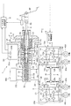
図1は、本実施例1のブレーキ制御装置1の全体構成を示す。FL輪は左前輪、FR輪は右前輪、RL輪は左後輪、RR輪は右後輪である。また、矢印付きの破線は信号線であり、矢印の向きによって信号の流れを表す。
[Configuration of brake control device]
FIG. 1 shows an overall configuration of a
ブレーキ制御装置1は、マスタシリンダ2と、リザーバタンクRESと、ホイル圧制御機構3と、各輪FL,FR,RL,RRに設けられたホイルシリンダ4a〜4dと、マスタシリンダ2に接続して設けられたマスタ圧制御機構5およびインプットロッド6と、ブレーキ操作量検出装置7と、マスタ圧制御機構5を制御するマスタ圧制御装置8と、ホイル圧制御機構3を制御するホイル圧制御装置9と、を有している。
The
インプットロッド6は、ブレーキペダルBPとともに、マスタシリンダ2内の液圧(以下、マスタ圧Pmc)を加減圧する第1の加減圧手段を構成している。マスタ圧制御機構5およびマスタ圧制御装置8は、マスタシリンダ2のプライマリピストン2bとともに、マスタ圧Pmcを加減圧する第2の加減圧手段を構成している。
The
以下、説明のため、マスタシリンダ2の軸方向にx軸を設定し、ブレーキペダルBPの側を負方向と定義する。マスタシリンダ2はいわゆるタンデム型であり、シリンダ2a内にプライマリピストン2bおよびセカンダリピストン2cを有している。シリンダ2aの内周面と、プライマリピストン2bのx軸正方向側の面およびセカンダリピストン2cのx軸負方向側の面との間で、加圧室としてのプライマリ液室2dが形成されている。シリンダ2aの内周面とセカンダリピストン2cのx軸正方向側の面との間で、加圧室としてのセカンダリ液室2eが形成されている。
Hereinafter, for the sake of explanation, the x-axis is set in the axial direction of the master cylinder 2, and the brake pedal BP side is defined as the negative direction. The master cylinder 2 is a so-called tandem type, and has a
プライマリ液室2dは、ブレーキ回路10と連通可能に接続され、セカンダリ液室2eは、ブレーキ回路20と連通可能に接続されている。プライマリ液室2dの容積は、プライマリピストン2bおよびセカンダリピストン2cがシリンダ2a内で摺動することで変化する。プライマリ液室2dには、プライマリピストン2bをx軸負方向側に付勢する戻しバネ2fが設置されている。セカンダリ液室2eの容積は、セカンダリピストン2cがシリンダ2a内で摺動することで変化する。セカンダリ液室2eには、セカンダリピストン2cをx軸負方向側に付勢する戻しバネ2gが設置されている。
The
インプットロッド6のx軸正方向側の一端6aは、プライマリピストン2bの隔壁2hを貫通し、プライマリ液室2d内に設置されている。インプットロッド6の一端6aとプライマリピストン2bの隔壁2hとの間はシールされ、液密性が保たれているとともに、一端6aは隔壁2hに対してx軸方向に摺動可能に設けられている。一方、インプットロッド6のx軸負方向側の他端6bは、ブレーキペダルBPに連結されている。ブレーキペダルBPが踏まれるとインプットロッド6はx軸正方向側に移動し、ブレーキペダルBPが戻されるとインプットロッド6はx軸負方向側に移動する。
One
プライマリ液室2dの作動液は、インプットロッド6または(駆動モータ50により駆動される)プライマリピストン2bがx軸正方向側へ推進することによって加圧される。加圧された作動液は、ブレーキ回路10を経由してホイル圧制御機構3に供給される。また、加圧されたプライマリ液室2dの圧力により、セカンダリピストン2cがx軸正方向側へ推進する。セカンダリ液室2eの作動液は、セカンダリピストン2cの上記推進によって加圧され、ブレーキ回路20を経由してホイル圧制御機構3に供給される。
The hydraulic fluid in the
このようにインプットロッド6がブレーキペダルBPと連動して移動し、プライマリ液室2dを加圧する構成により、万一、故障により駆動モータ50が停止した場合にも、運転者のブレーキ操作によってマスタ圧Pmcを上昇でき、所定のブレーキ力が確保される。また、マスタ圧Pmcに応じた力がインプットロッド6を介してブレーキペダルBPに作用し、ブレーキペダル反力として運転者に伝達されるため、上記構成を採らない場合に必要な、ブレーキペダル反力を生成するバネ等の装置が不要となる。よって、ブレーキ制御装置の小型化・軽量化が図られ、車両への搭載性が向上する。
In this way, the
インプットロッド6の他端6b側には、運転者の要求ブレーキ力を検出するブレーキ操作量検出装置7が設けられている。ブレーキ操作量検出装置7は、インプットロッド6のx軸方向変位量を検出する変位センサ(ブレーキペダルBPのストロークセンサ)である。本実施例1では、2つの変位センサ7a,7bが設けられており、これらにより検出された変位量はそれぞれマスタ圧制御装置8に入力される。このように複数個の変位センサを組み合わせることにより、万一、故障により1つのセンサからの信号が途絶えた場合にも、残りのセンサによって運転者のブレーキ要求が検出・認知されるため、フェールセーフが確保される。
On the
また、ブレーキ操作量検出装置7としては、ブレーキペダルBPの踏力を検出する踏力センサや、ストロークセンサと踏力センサを組み合わせた構成であってもよい。 Further, the brake operation amount detection device 7 may have a configuration in which a pedal force sensor for detecting the pedal force of the brake pedal BP, or a combination of a stroke sensor and a pedal force sensor.
リザーバタンクRESは、隔壁によって互いに仕切られた少なくとも2つの液室を有している。各液室はそれぞれブレーキ回路10j,20jを介して、マスタシリンダ2のプライマリ液室2dおよびセカンダリ液室2eと連通可能に接続されている。
The reservoir tank RES has at least two liquid chambers separated from each other by a partition wall. Each fluid chamber is connected to the
ホイル圧制御機構3は、ABS制御や車両挙動安定化制御等を実行可能な液圧制御ユニットであり、マスタシリンダ2等で加圧された作動液を、ホイル圧制御装置9の制御指令に従って、各ホイルシリンダ4a〜4dへ供給する。
The wheel
ホイルシリンダ4a〜4dは、シリンダ、ピストン、パッド等を有しており、ホイル圧制御機構3から供給された作動液によって上記ピストンが推進され、このピストンに連結されたパッドがディスクロータ40a〜40dに押圧される周知のものである。なお、ディスクロータ40a〜40dはそれぞれ車輪FL,FR,RL,RRと一体回転し、ディスクロータ40a〜40dに作用するブレーキトルクは、車輪FL,FR,RL,RRと路面との間に作用するブレーキ力となる。
The
マスタ圧制御機構5は、プライマリピストン2bの変位量すなわちマスタ圧Pmcを、マスタ圧制御装置8の制御指令に従って制御するものであり、駆動モータ50と、減速装置51と、回転−並進変換装置55と、を有している。
The master
マスタ圧制御装置8は演算処理回路であり、ブレーキ操作量検出装置7や駆動モータ50からのセンサ信号、およびホイル圧制御装置9からの制御指令等に基づいて、駆動モータ50の作動を制御する。
The master
ホイル圧制御装置9は演算処理回路であり、先行車との車間距離や道路情報、および車両状態量(例えば、ヨーレート、前後加速度、横加速度、ハンドル舵角、車輪速、車体速等)に基づき、各輪FL,FR,RL,RRで発生させるべき目標ブレーキ力を算出する。そして、この算出結果に基づき、ホイル圧制御機構3の各アクチュエータ(ソレノイドバルブやポンプ)の作動を制御する。
The wheel
なお、マスタ圧制御装置8とホイル圧制御装置9とは双方向の通信を行っており、制御指令、車両状態量、故障情報、および作動状態等の状態を共有している。
Note that the master
[ホイル圧制御機構]
以下、ホイル圧制御機構3の油圧回路構成を説明する。
[Foil pressure control mechanism]
Hereinafter, the hydraulic circuit configuration of the wheel
ブレーキ回路は独立した2つのブレーキ系統を有し、プライマリ系統およびセカンダリ系統に分かれている。プライマリ系統は、プライマリ液室2dから作動液の供給を受け、ブレーキ回路10を介してFL輪とRR輪のブレーキ力を制御する。セカンダリ系統は、セカンダリ液室2eから作動液の供給を受け、ブレーキ回路20を介してFR輪とRL輪のブレーキ力を制御する。このようにいわゆるX配管構造であるため、一方のブレーキ系統が失陥した場合でも、他方の正常なブレーキ系統によって対角2輪分のブレーキ力が確保され、車両の挙動が安定に保たれる。以下、プライマリ系統を例にとって説明する。
The brake circuit has two independent brake systems and is divided into a primary system and a secondary system. The primary system receives the supply of hydraulic fluid from the
ブレーキ回路10のマスタシリンダ2側(以下、上流という)からホイルシリンダ4a、4d側(以下、下流という)に向かう途中には、アウト側ゲート弁11が設けられている。アウト側ゲート弁11は、マスタシリンダ2で加圧された作動液をホイルシリンダ4a、4dに供給する際に開弁される。
On the way from the master cylinder 2 side (hereinafter referred to as upstream) of the
アウト側ゲート弁11が設けられたブレーキ回路10kの下流はブレーキ回路10a,10bに分岐し、ブレーキ回路10a,10bは、それぞれブレーキ回路10l、10mを介してホイルシリンダ4a、4dに接続している。ブレーキ回路10a,10b上には、それぞれ増圧弁12,13が設けられている。増圧弁12,13は、マスタシリンダ2または後述のポンプPで加圧された作動液をホイルシリンダ4a、4dに供給する際に開弁される。
The downstream side of the
ブレーキ回路10a,10bには、増圧弁12,13の下流側で、リターン回路10c,10dがそれぞれ接続している。リターン回路10c,10d上にはそれぞれ減圧弁14,15が設けられている。減圧弁14,15は、ホイルシリンダ4a、4d内の圧力(以下、ホイル圧Pwc)を減圧する際に開弁される。リターン回路10c,10dは合流してリターン回路10eを形成し、リターン回路10eはリザーバ16に接続している。
一方、ブレーキ回路10はアウト側ゲート弁11の上流で分岐し、吸入回路10gを形成している。吸入回路10g上には、吸入回路10gの連通・遮断を切り換えるイン側ゲート弁17が設けられている。イン側ゲート弁17は、例えば、マスタシリンダ2で加圧された作動液を後述のポンプPで昇圧してホイルシリンダ4a、4dに供給する際に開弁される。吸入回路10gは、リザーバ16からのリターン回路10fと合流して吸入回路10hを形成している。
On the other hand, the
ブレーキ回路10には、マスタシリンダ2以外の液圧源として、作動液の吸入・吐出を行うポンプPが接続されている。ポンプPはギヤ式のポンプであって、第1ポンプP1および第2ポンプP2を備えている。ポンプPは、例えば、車両挙動安定化制御等の自動ブレーキ制御を行う際、マスタシリンダ2の作動圧を超える圧力が必要な場合に、マスタ圧Pmcを昇圧してホイルシリンダ4a、4dに供給する。第1ポンプP1は、吸入回路10hおよび吐出回路10iと接続し、吐出回路10iを介してブレーキ回路10kと接続している。
The
モータMは、DC(直流)ブラシレスモータであり、その出力軸にはポンプP1、P2が連結されている。モータMは、ホイル圧制御装置9の制御指令に基づき供給される電力によって作動し、ポンプP1、P2を駆動する。
The motor M is a DC (direct current) brushless motor, and pumps P1 and P2 are connected to its output shaft. The motor M is operated by the electric power supplied based on the control command of the wheel
アウト側ゲート弁11、イン側ゲート弁17、増圧弁12,13、および減圧弁14,15は、ソレノイドへの通電により弁の開閉が行われる電磁式のものであり、ホイル圧制御装置9が出力する駆動信号に応じた大きさの駆動電流が通電されることで、弁の開閉量が各弁個々に制御される。
The out-
なお、アウト側ゲート弁11および増圧弁12,13は常開弁であり、イン側ゲート弁17および減圧弁14,15は常閉弁である。これにより万一、故障によりいずれかの弁への電力供給が停止した場合であっても、マスタシリンダ2で加圧された作動液が全てホイルシリンダ4a、4dに到達する回路構成となるため、運転者の要求通りのブレーキ力を発生させることができる。ただし、アウト側ゲート弁11および増圧弁12,13を常閉弁とし、イン側ゲート弁17および減圧弁14,15を常開弁とすることとしてもよく、特に限定しない。
The out-
ブレーキ回路20側の油圧回路も、上記ブレーキ回路10側と同様に構成されている。
The hydraulic circuit on the
ブレーキ回路10(マスタシリンダ2とホイル圧制御機構3との間)、およびブレーキ回路20(ホイル圧制御機構3内)には、それぞれ、マスタ圧Pmc(プライマリ液室2dおよびセカンダリ液室2eの圧力)を検出する圧力センサであるマスタ圧センサ3a,3bが設けられている。マスタ圧センサ3a,3bが検出したマスタ圧Pmcの情報は、マスタ圧制御装置8およびホイル圧制御装置9に入力される。なお、マスタ圧センサの個数および設置位置に関しては、制御性やフェールセーフ等を考慮して任意に決定できる。
In the brake circuit 10 (between the master cylinder 2 and the wheel pressure control mechanism 3) and the brake circuit 20 (in the wheel pressure control mechanism 3), the master pressure Pmc (the pressure in the
以下、ブレーキ制御時のホイル圧制御機構3の動作を説明する。
通常制御時には、マスタシリンダ2の作動液がブレーキ回路10,20を介して各ホイルシリンダ4a〜4dに供給され、ブレーキ力が発生する。
Hereinafter, the operation of the wheel
During normal control, the hydraulic fluid in the master cylinder 2 is supplied to the
ABS制御時には、車輪FLを例にとると、ホイルシリンダ4aに接続されている減圧弁14を開弁させるとともに増圧弁12を閉弁させ、ホイルシリンダ4aの作動液をリザーバ16に戻すことで減圧を行う。また、車輪FLがロック傾向から回復したら、増圧弁12を開弁させるとともに減圧弁14を閉弁させることで増圧を行う。このときポンプPは、リザーバ16に逃がした作動液をブレーキ回路10kに戻す。
At the time of ABS control, taking the wheel FL as an example, the
車両挙動安定化制御等の自動ブレーキ制御時には、アウト側ゲート弁11,21を閉弁させる一方で、イン側ゲート弁17,27を開弁させる。同時にポンプPを作動させ、吸入回路10g,10h,20g,20h、吐出回路10i,20iを介してマスタシリンダ2からブレーキ回路10k,20kに向けて作動液を吐出させる。さらに、ホイル圧Pwcが必要なブレーキ力に応じた目標圧となるようにアウト側ゲート弁11,21または増圧弁12,13,22,23を制御する。
During automatic brake control such as vehicle behavior stabilization control, the out-
(ホイル圧制御機構における倍力制御構成)
運転者がブレーキペダルを踏み込むと、マスタ圧が発生する。通常、倍力システムでは、ブレーキペダルの軸力(インプットロッド6の推力に相当)を増幅する機構(マスタ圧制御機構5やマスタ圧制御装置8に相当)を備えることで高いマスタ圧を発生させる。しかし、上記機構が故障した場合は、マスタ圧自体を高くすることができなくなる。
(A boost control structure in the foil pressure control mechanism)
When the driver depresses the brake pedal, master pressure is generated. Normally, a booster system generates a high master pressure by providing a mechanism (corresponding to the master
ここで、運転者のブレーキペダル踏力が発生させるマスタ圧に比べてホイル圧が高くなれば、倍力していることと等価である。よって、マスタ圧に対して所定の倍力比に応じた差圧分だけ高い目標ホイル圧を設定し、ホイル圧がこの目標ホイル圧に維持される状況を達成すれば、倍力システムを実現できる。よって、本実施例1のブレーキ制御装置1では、ホイル圧制御機構3において、上記差圧を維持する機能をアウト側ゲート弁11,21の制御により達成する(下記のバックアップモード1,2)。
Here, if the wheel pressure is higher than the master pressure generated by the driver's brake pedal depression force, it is equivalent to boosting. Therefore, a boost system can be realized by setting a target foil pressure that is higher than the master pressure by a differential pressure corresponding to a predetermined boost ratio and achieving a situation in which the foil pressure is maintained at the target foil pressure. . Therefore, in the
以下、ホイル圧制御機構3を用いた倍力制御構成について説明する。ホイル圧制御機構3では、ポンプP1,P2、イン側ゲート弁17,27、およびアウト側ゲート弁11,21の制御によって倍力システムを実現する。概要としては、イン側ゲート弁17,27を開弁してモータMの駆動制御によりポンプPが所定液圧を吐出可能な状態としておき、アウト側ゲート弁11,21を差圧制御することで倍力システムを実現する。以下、ブレーキ回路10側を例にとって、各構成の詳細について説明する。
Hereinafter, a boost control configuration using the wheel
(アウト側ゲート弁の制御について)
アウト側ゲート弁11は、電磁吸引力を発生するコイルと、この電磁吸引力に応じて作動し開弁量を調節する可動子と、ブレーキ回路10kおよびブレーキ回路10が接続されたバルブボディから構成されている。
(Regarding control of out-side gate valve)
The out-
可動子には、ホイルシリンダ4a、4d側の圧力に応じた開弁方向の力Fwcと、マスタ圧Pmcに応じた閉弁方向の力Fmcと、電磁吸引力に応じた閉弁方向の力Fbが作用する。尚、アウト側ゲート弁11は常開弁であるため実際にはスプリングにより開弁方向の力が作用しているが、ここでは無視して考える(考慮する場合はオフセット値等を与えればよい)。
The mover includes a valve opening direction force Fwc corresponding to the pressure on the
可動子は、これらの力の釣り合いが取れた位置で停止する。言い換えると、可動子は、Fmc+Fb−Fwc=0(Fb = Fwc−Fmc)のとき停止し、Fmc+Fb−Fwc>0(Fb>Fwc− Fmc)のとき閉弁方向に移動し、Fmc+Fb−Fwc<0(Fb<Fwc−Fmc)のとき開弁方向に移動する。Fmcはマスタ圧Pmcと相関する値であり、Fwcはホイル圧Pwcと相関する値であることから、倍力制御によって達成すべきマスタ圧Pmcとホイル圧Pwcとの差圧である目標差圧ΔPは、(Fwc−Fmc)と相関がある。一方、上記のようにFbと(Fwc−Fmc)との大小関係によって可動子の位置が決まる。よって、目標差圧ΔPに相当する(Fwc−Fmc)と同じ大きさの電磁吸引力Fbを設定すれば、目標差圧ΔPを確保できる可動子の位置が自動的に決定される。 The mover stops at a position where these forces are balanced. In other words, the mover stops when Fmc + Fb−Fwc = 0 (Fb = Fwc−Fmc), moves in the valve closing direction when Fmc + Fb−Fwc> 0 (Fb> Fwc−Fmc), and Fmc + Fb−Fwc <0. Moves in the valve opening direction when (Fb <Fwc−Fmc). Since Fmc is a value that correlates with the master pressure Pmc, and Fwc is a value that correlates with the wheel pressure Pwc, the target differential pressure ΔP that is the differential pressure between the master pressure Pmc and the wheel pressure Pwc to be achieved by the boost control. Is correlated with (Fwc−Fmc). On the other hand, as described above, the position of the mover is determined by the magnitude relationship between Fb and (Fwc−Fmc). Therefore, if an electromagnetic attractive force Fb having the same magnitude as (Fwc−Fmc) corresponding to the target differential pressure ΔP is set, the position of the mover that can ensure the target differential pressure ΔP is automatically determined.
目標差圧ΔPは、マスタ圧センサ3a,3bにより検出されたマスタ圧Pmcと目標倍力比とに基づき設定される。なお、ブレーキ操作量検出装置7により検出されたブレーキ操作量をマスタ圧制御装置8から受信し、これを用いて目標差圧ΔPを設定してもよい。
The target differential pressure ΔP is set based on the master pressure Pmc detected by the
今、ホイル圧制御機構3を用いて倍力制御を実現することを考えると、アウト側ゲート弁11よりもホイルシリンダ4a、4d側でポンプP1等を用いて高い圧力を発生させ、マスタ圧Pmcよりホイル圧Pwcが高い状態を設定することとなる。このとき、電磁吸引力Fbを、目標差圧ΔPに相当する値に設定しておけば、ホイルシリンダ4a、4d側で行われる増圧作用に応じて自動的に可動子の位置が変更され、目標とするホイル圧Pwcを得ることができる。例えば、ホイル圧Pwcが目標値より高いときは可動子が開弁側に移動して、目標差圧ΔPが実現されるまで自動的にホイルシリンダ4a、4dのブレーキ液をマスタシリンダ2側に排出し、ホイル圧Pwcを減圧する。すなわち、ホイル圧Pwcの検出センサ等を用いたフィードバック制御を行わなくとも、自動的にホイル圧Pwcが所望の値に制御される。
Considering the realization of boost control using the wheel
これにより、複雑なフィードバック制御が不要となるとともに、モータMの制御誤差をアウト側ゲート弁11で吸収することが可能となる。言い換えると、運転者のブレーキペダル踏力に相当するマスタ圧Pmcに基づき、フィードフォワード的に目標差圧ΔPに相当する電磁吸引力Fbが与えられれば、アウト側ゲート弁11は目標差圧ΔPを達成し、機械的フィードバック機構と同様の機能を発揮する。このため、電子的フィードバック制御機構で必要となる制御対象の状態を検出するセンサ等が不要であり、制御安定性が非常に高い。
As a result, complicated feedback control becomes unnecessary, and the control error of the motor M can be absorbed by the out-
(モータ駆動制御について)
アウト側ゲート弁11を上記のように制御している間は、基本的にイン側ゲート弁17を開弁してポンプP1を駆動させる。ポンプP1はモータMにより駆動されることから、例えば、マスタ圧Pmcに応じて設定される倍力されたホイル圧Pwcを供給可能な吐出圧を実現する最低回転数等を設定し、その最低回転数になるようにモータMを駆動する。すると、ポンプP1から必要な液圧が確保されるため、ホイル圧Pwcを所望の液圧に制御することができる。
(About motor drive control)
While the out
なお、上記のように、ポンプP1は、ブレーキ回路10g,10hを介してマスタシリンダ2のブレーキ液を吸入し、ホイルシリンダ4a、4d側に吐出する。よって、ストロークシミュレータ等を備えることなく、運転者のブレーキペダルストロークを確保することができる。また、マスタ圧Pmcのみ検出すればよいため、ストロークセンサ(ブレーキ操作量検出装置7)等が故障した場合であっても、倍力システムを実現することができる(後述するバックアップモード1,2等を実行可能である)。
As described above, the pump P1 sucks the brake fluid in the master cylinder 2 through the
[マスタ圧制御機構]
以下、マスタ圧制御機構5の構成と動作について説明する。
駆動モータ50は三相DCブラシレスモータであり、マスタ圧制御装置8の制御指令に基づき供給される電力によって動作し、所望の回転トルクを発生する。
[Master pressure control mechanism]
Hereinafter, the configuration and operation of the master
The
減速装置51は、駆動モータ50の出力回転をプーリ減速方式により減速する。減速装置51は、駆動モータ50の出力軸に設けられた小径の駆動側プーリ52と、回転−並進変換装置55のボールネジナット56に設けられた大径の従動側プーリ53と、駆動側および従動側プーリ52,53に巻き掛けられたベルト54と、を有している。減速装置51は、駆動モータ50の回転トルクを、減速比(駆動側および従動側プーリ52,53の半径比)分だけ増幅させて、回転−並進変換装置55に伝達する。
The
なお、駆動モータ50の回転トルクが十分に大きく、減速によるトルク増幅が必要でない場合には、減速装置51を省略して、駆動モータ50と回転−並進変換装置55とを直結することとしてもよい。この場合、減速装置51の介在に起因して発生する、信頼性や静粛性、および搭載性等に関する諸問題を回避できる。
If the rotational torque of the
回転−並進変換装置55は、駆動モータ50の回転動力を並進動力に変換し、この並進動力によりプライマリピストン2bを押圧する。本実施例1では、動力変換機構としてボールネジ方式を採用しており、回転−並進変換装置55は、ボールネジナット56と、ボールネジ軸57と、可動部材58と、戻しバネ59と、を有している。
The rotation-
マスタシリンダ2のx軸負方向側には第1ハウジング部材HSG1が接続され、第1ハウジング部材HSG1のx軸負方向側には第2ハウジング部材HSG2が接続されている。ボールネジナット56は、第2ハウジング部材HSG2内に設けられたベアリングBRGの内周に、軸回転可能に設置されている。ボールネジナット56のx軸負方向側の外周には、従動側プーリ53が嵌合されている。ボールネジナット56の内周には、中空のボールネジ軸57が螺合している。ボールネジナット56とボールネジ軸57との間の隙間には、複数のボールが回転移動可能に設置されている。
A first housing member HSG1 is connected to the x-axis negative direction side of the master cylinder 2, and a second housing member HSG2 is connected to the x-axis negative direction side of the first housing member HSG1. The ball screw
ボールネジ軸57のx軸正方向側の端には、可動部材58が一体に設けられている。可動部材58のx軸正方向側の面には、プライマリピストン2bが接合している。プライマリピストン2bは、第1ハウジング部材HSG1内に収容されている。プライマリピストン2bのx軸正方向側の端は第1ハウジング部材HSG1から突出してマスタシリンダ2のシリンダ2aの内周に嵌合している。
A
第1ハウジング部材HSG1内では、プライマリピストン2bの外周に、戻しバネ59が設置されている。戻しバネ59のx軸正方向側の端は第1ハウジング部材HSG1内部のx軸正方向側の面Aに固定される一方、x軸負方向側の端は可動部材58に係合している。戻しバネ59は、面Aと可動部材28との間でx軸方向に押し縮められて設置され、可動部材58およびボールネジ軸57をx軸負方向側に付勢している。
In the first housing member HSG1, a
従動側プーリ53が回転するとボールネジナット56が一体に回転し、このボールネジナット56の回転運動により、ボールネジ軸57がx軸方向に並進運動する。x軸正方向側へのボールネジ軸57の並進運動の推力により、可動部材58を介して、プライマリピストン2bがx軸正方向側に押圧される。なお、図1では、ブレーキ非作動時にボールネジ軸57がx軸負方向側に最大変位した初期位置にある状態を示す。
When the driven
一方、ボールネジ軸57には、上記x軸正方向側への推力と反対方向(x軸負方向側)に、戻しバネ59の弾性力が作用する。これによりブレーキ中、すなわちプライマリピストン2bがx軸正方向側に押圧されマスタ圧Pmcが加圧されている状態で、万一、故障により駆動モータ50が停止し、ボールネジ軸57の戻し制御が不能となった場合でも、戻しバネ59の反力によりボールネジ軸27が初期位置に戻される。これによりマスタ圧Pmcがゼロ付近まで低下するため、ブレーキ力の引きずりの発生が防止され、この引きずりに起因して車両挙動が不安定になる事態が回避される。
On the other hand, the elastic force of the
また、インプットロッド6とプライマリピストン2bとの間に画成された環状空間Bには、一対のバネ6d、6eが配設されている。一対のバネ6d、6eは、その各一端がインプットロッド6に設けられたフランジ部6cに係止され、バネ6dの他端がプライマリピストン2bの隔壁2hに係止され、バネ6eの他端が可動部材58に係止されている。一対のバネ6d、6eは、プライマリピストン2bに対してインプットロッド6を両者の相対変位の中立位置に向けて付勢し、ブレーキ非作動時にインプットロッド6とプライマリピストン2bとを相対移動の中立位置に保持する機能を有している。また、インプットロッド6とプライマリピストン2bとが中立位置からいずれかの方向に相対変位したとき、一対のバネ6d、6eにより、プライマリピストン2bに対してインプットロッド6を中立位置に戻す付勢力が作用する。
A pair of
なお、駆動モータ50には回転角検出センサ50aが設けられており、これにより検出されるモータ出力軸の位置信号がマスタ圧制御装置8に入力される。マスタ圧制御装置8は、入力された位置信号に基づき駆動モータ50の回転角を算出し、この回転角に基づき回転−並進変換装置25の推進量、すなわちプライマリピストン2bのx軸方向変位量を算出する。
The
また、駆動モータ50には温度センサ50bが設けられており、検出された駆動モータ50の温度情報はマスタ圧制御装置8に入力される。
The
(倍力制御処理)
次に、マスタ圧制御機構5とマスタ圧制御装置8による、インプットロッド6の推力の増幅作用について説明する。
(Boost control process)
Next, the amplifying action of the thrust of the
マスタ圧制御機構5およびマスタ圧制御装置8は、運転者のブレーキ操作によるインプットロッド6の変位量に応じて、プライマリピストン2bを変位させる。これによりプライマリ液室2dが、インプットロッド6の推力に加えてプライマリピストン2bの推力によって加圧され、マスタ圧Pmcが調整される。すなわちインプットロッド6の推力が増幅される。増幅比(以下、倍力比α)は、プライマリ液室2dにおけるインプットロッド6とプライマリピストン2bの軸直方向断面積(以下、それぞれ受圧面積AIRおよびAPP)の比等により、以下のように決定される。
The master
マスタ圧Pmcの液圧調整は、式(1)で示される圧力平衡関係をもって行われる。
Pmc=(FIR+K×△x)/AIR=(FPP−K×△x)/APP …(1)
ここで、圧力平衡式(1)における各要素は、以下のとおりである。
Pmc:プライマリ液室2dの液圧(マスタ圧)、
FIR :インプットロッド6の推力、
FPP :プライマリピストン2bの推力、
AIR :インプットロッド6の受圧面積、
APP :プライマリピストン2bの受圧面積、
K :バネ6d、6eのバネ定数、
Δx:インプットロッド6とプライマリピストン2bとの相対変位量。
The hydraulic pressure adjustment of the master pressure Pmc is performed with a pressure equilibrium relationship represented by the equation (1).
Pmc = (F IR + K × Δx) / A IR = (F PP −K × Δx) / A PP (1)
Here, each element in the pressure balance equation (1) is as follows.
Pmc: Fluid pressure (master pressure) in the
F IR : Thrust of
F PP : Thrust of
A IR : pressure receiving area of the
A PP : pressure receiving area of the
K: spring constant of
Δx: relative displacement between the
ここで相対変位量Δxは、インプットロッド6の変位をxIR、プライマリピストン2bの変位をxPPとして、Δx=xPP−xIRと定義する。よって、Δxは、相対移動の中立位置では0、インプットロッド6に対してプライマリピストン2bが前進(x軸正方向側へ変位)する方向では正符号、その逆方向では負符号となる。なお、圧力平衡式(1)ではシールの摺動抵抗を無視している。プライマリピストン2bの推力FPPは、駆動モータ50の電流値から推定できる。
一方、倍力比αは、下記(2)式のように表わされる。
α=PM/C×(APP+AIR)/FIR …(2)
よって、この(2)式に上記(1)式のPM/Cを代入すると、倍力比αは下記(3)式のようになる。
α=(1+K×Δx/FIR)×(AIR+APP)/AIR …(3)
Here the relative displacement [Delta] x is the displacement of the input rod 6 x IR, the displacement of
On the other hand, the boost ratio α is expressed by the following equation (2).
α = P M / C × (A PP + A IR ) / F IR (2)
Therefore, when P M / C of the above equation (1) is substituted into this equation (2), the boost ratio α is expressed by the following equation (3).
α = (1 + K × Δx / F IR ) × (A IR + A PP ) / A IR (3)
倍力制御では、目標のマスタ圧特性が得られるように、駆動モータ50(プライマリピストン2bの変位xPP)を制御する。ここでマスタ圧特性とは、インプットロッド6の変位xIRに対するマスタ圧Pmcの変化の特性を指す。インプットロッド6の変位xIRに対するプライマリピストン2bの変位xPPを示すストローク特性と、上記目標マスタ圧特性とに対応して、インプットロッド6の変位xIRに対する相対変位量Δxの変化を示す目標変位量算出特性が得られる。検証により得られた目標変位量算出特性データに基づき、相対変位量Δxの目標値(以下、目標変位量Δx*)が算出される。
In the boost control, the drive motor 50 (displacement x PP of the
すなわち、目標変位量算出特性は、インプットロッド6の変位xIRに対する目標変位量Δx*の変化の特性を示し、インプットロッド6の1つの変位量xIRに対応して1つの目標変位量Δx*が定まる。検出されたインプットロッド6の変位量xIRに対応して決定される目標変位量Δx*を実現するように駆動モータ50の回転(プライマリピストン2bの変位量xPP)を制御すると、目標変位量Δx*に対応する大きさのマスタ圧Pmcがマスタシリンダ2で発生する。
That is, the target displacement calculation characteristic shows a characteristic of the target displacement [Delta] x * changes with respect to the displacement x IR of the
ここで、上記のようにインプットロッド6の変位量xIRはブレーキ操作量検出装置7により検出され、プライマリピストン2bの変位量xPPは回転角検出センサ50aの信号に基づき算出され、相対変位量Δxは上記検出(算出)された変位量の差により求められる。倍力制御では、具体的には、上記検出した変位量xIRと目標変位量算出特性とに基づいて目標変位量Δx*を設定し、上記検出(算出)された相対変位量Δxが目標変位量Δx*と一致するように駆動モータ50を制御(フィードバック制御)する。なお、プライマリピストン2bの変位量xPPを検出するストロークセンサを別途設けることとしてもよい。
Here, as described above, the displacement amount x IR of the
このように高価な踏力センサを用いることなく倍力制御を行うため、その分、コストを低減できる。また、相対変位量Δxが任意の所定値となるように駆動モータ50を制御することにより、受圧面積比(AIR+APP)/AIRで定まる倍力比よりも大きな倍力比や小さな倍力比を得ることができ、所望の倍力比に基づく制動力を得ることができる。
Since boost control is performed without using an expensive pedal force sensor in this way, the cost can be reduced accordingly. Further, by controlling the
一定倍力制御は、インプットロッド6およびプライマリピストン2bを一体的に変位させる。すなわちインプットロッド6に対してプライマリピストン2bが常に上記中立位置となり相対変位量Δx=0で変位するように、駆動モータ50を制御するものである。このようにΔx=0となるようにプライマリピストン2bを変位させた場合、上記(3)式により、倍力比αは、α=(AIR+APP)/AIRとして一意に定まる。よって、必要な倍力比に基づいてAIRおよびAPPを設定し、変位量xPPがインプットロッド6の変位量xIRに等しくなるようにプライマリピストン2bを制御することで、常に一定の(上記必要な)倍力比を得ることができる。
In the constant boost control, the
一定倍力制御における目標マスタ圧特性は、インプットロッド6の前進(x軸正方向側への変位)に伴い発生するマスタ圧Pmcが2次曲線、3次曲線、あるいはこれらにそれ以上の高次曲線等が複合した多次曲線(以下、これらを総称して多次曲線という)状に大きくなる。また、一定倍力制御は、インプットロッド6の変位xIRと同じ量だけプライマリピストン2bが変位する(xPP=xIR)ストローク特性を有している。このストローク特性と上記目標マスタ圧特性とに基づき得られる目標変位量算出特性では、インプットロッド6のあらゆる変位xIRに対して目標変位量Δx*が0となる。
The target master pressure characteristic in constant boost control is that the master pressure Pmc generated as the
これに対して、倍力可変制御は、目標変位量Δx*を正の所定値に設定し、相対変位量Δxがこの所定値となるように駆動モータ50を制御する。これにより、マスタ圧Pmcを増加する方向へインプットロッド6が前進移動するに従い、インプットロッド6の変位量xIRに比べてプライマリピストン2bの変位量xPPが大きくなるようにするものである。上記(3)式により、倍力比αは、(1+K×Δx/FIR)倍の大きさとなる。すなわち、インプットロッド6の変位量xIRに比例ゲイン(1+K×Δx/FIR)を乗じた量だけプライマリピストン2bを変位させることと同義となる。このようにΔxに応じて倍力比αが可変となり、マスタ圧制御機構5が倍力源として働いて、運転者の要求通りのブレーキ力を発生させつつペダル踏力の大きな低減を図ることができる。
On the other hand, in variable boost control, the target displacement amount Δx * is set to a positive predetermined value, and the
すなわち、制御性の観点からは上記比例ゲイン(1+K×Δx/FIR)は1であることが望ましいが、例えば緊急ブレーキ等により運転者のブレーキ操作量を上回るブレーキ力が必要な場合には、一時的に、1を上回る値に上記比例ゲインを変更することができる。これにより、同量のブレーキ操作量でも、マスタ圧Pmcを通常時(上記比例ゲインが1の場合)に比べて引き上げることができるため、より大きなブレーキ力を発生させることができる。ここで、緊急ブレーキの判定は、例えば、ブレーキ操作量検出装置7の信号の時間変化率が所定値を上回るか否かで判定できる。 That is, from the viewpoint of controllability, the proportional gain (1 + K × Δx / F IR ) is preferably 1. However, for example, when a braking force exceeding the driver's brake operation amount is required by an emergency brake or the like, Temporarily, the proportional gain can be changed to a value greater than 1. As a result, even with the same amount of brake operation, the master pressure Pmc can be increased compared to the normal time (when the proportional gain is 1), so that a larger braking force can be generated. Here, the emergency brake can be determined, for example, based on whether or not the time change rate of the signal of the brake operation amount detection device 7 exceeds a predetermined value.
このように倍力可変制御は、インプットロッド6の前進に対してプライマリピストン2bの前進をより進め、インプットロッド6に対するプライマリピストン2bの相対変位量Δxがインプットロッド6の前進に伴い大きくなり、これに対応してインプットロッド6の前進に伴うマスタ圧Pmcの増加が一定倍力制御よりも大きくなるように駆動モータ50を制御する方法である。
Thus, in the variable boost control, the
倍力可変制御における目標マスタ圧特性は、インプットロッド6の前進(x軸正方向側への変位)に伴い発生するマスタ圧Pmcの増加が一定倍力制御よりも大きくなる(多次曲線状に増加するマスタ圧特性がより急峻になる)。また、倍力可変制御は、インプットロッド6の変位xIRの増加に対するプライマリピストン2bの変位xPPの増加分が1よりも大きいストローク特性を有している。このストローク特性と上記目標マスタ圧特性とに基づき得られる目標変位量算出特性では、インプットロッド6の変位xIRが増加するに応じて目標変位量Δx*が所定の割合で増加する。
In the target master pressure characteristic in variable boost control, the increase in the master pressure Pmc generated as the
また、倍力可変制御として、上記制御〔マスタ圧Pmcを増加する方向へインプットロッド6が移動するに従い、インプットロッド6の変位量xIRに比べてプライマリピストン2bの変位量xPPが大きくなるように駆動モータ50を制御すること〕に加え、マスタ圧Pmcを増加する方向へインプットロッド6が移動するに従い、インプットロッド6の変位量xIRに比べてプライマリピストン2bの変位量xPPが小さくなるように駆動モータ50を制御することを含めてもよい。このように1を下回る値に上記比例ゲインを変更することで、ハイブリッド車両の回生ブレーキ力分だけ液圧ブレーキを減圧する回生協調ブレーキ制御に適用することも可能である。
As the variable boost control, the above-mentioned control [the displacement x PP of the
また、相対変位量Δxに基づく上記倍力可変制御に換えて、マスタ圧センサ3a,3bで検出したマスタ圧Pmcが目標マスタ圧と一致するように、マスタ圧制御機構5(駆動モータ50)をフィードバック制御することで倍力可変制御を行うこととしてもよい。これらの倍力可変制御方法の切り換えは、状況に応じて行うことができる。
Further, instead of the variable boost control based on the relative displacement amount Δx, the master pressure control mechanism 5 (drive motor 50) is changed so that the master pressure Pmc detected by the
なお、相対変位量Δxに基づく上記倍力可変制御では、検出されたマスタ圧Pmcに直接基づいて制御を行わないため、正常に所期のマスタ圧Pmcが発生しているか否かをチェックするために、別途、検出したマスタ圧Pmcを目標マスタ圧特性におけるxIRに応じたマスタ圧(目標マスタ圧)と照合することで、フェール(失陥)対策を行っている。 In the variable boost control based on the relative displacement amount Δx, control is not performed directly based on the detected master pressure Pmc, so that it is normally checked whether the desired master pressure Pmc is generated. Separately, the detected master pressure Pmc is checked against the master pressure (target master pressure) corresponding to x IR in the target master pressure characteristic, thereby taking measures against failure.
(自動ブレーキ制御処理)
運転者のブレーキ操作が行われない(インプットロッド6が変位しない)自動ブレーキ制御時には、マスタ圧制御機構5とマスタ圧制御装置8により、マスタ圧Pmcを自動的に発生させる制御(以下、自動ブレーキ制御処理)が行われる。自動ブレーキ制御処理は、マスタシリンダ2の作動圧を自動ブレーキ制御時の要求液圧(以下、自動ブレーキ要求液圧)に調節すべく、プライマリピストン2bを前進および後退させる制御処理であり、例えば、車両追従制御、車線逸脱回避制御、障害物回避制御等での自動ブレーキ制御に適用可能である。なお、自動ブレーキ要求液圧は、上記各制御の制御装置から出力される目標ブレーキ力等に基づき演算される。
(Automatic brake control processing)
At the time of automatic brake control in which the driver does not perform the brake operation (the
この場合のプライマリピストン2bの制御方法としては、テーブルとして事前に取得したプライマリピストン2bの変位量xPPとマスタ圧Pmcとの関係に基づき、自動ブレーキ要求液圧を実現するプライマリピストン2bの変位量xPPを抽出し、これを目標変位量とする方法がある。この場合、回転角検出センサ50aで検出したモータ回転角をプライマリピストン2bの変位量xPPへ換算し、この換算した変位量が上記目標変位量と一致するように駆動モータ50をフィードバック制御する。
As a control method of the
その他、マスタ圧センサ3a,3bで検出されたマスタ圧Pmcが自動ブレーキ要求液圧と一致するようにプライマリピストン2bの変位量xPPをフィードバック制御する方法等があるが、いずれの方法を採ってもかまわない。なお、自動ブレーキ要求液圧は外部ユニットから受信することが可能である。
In addition, there is a method of feedback-controlling the displacement amount x PP of the
なお、テーブルに基づく上記の自動ブレーキ制御処理では、検出されたマスタ圧Pmcに直接基づいて制御を行わないため、正常に所期のマスタ圧Pmc(自動ブレーキ要求液圧)が発生しているか否かをチェックするために、別途、検出したマスタ圧Pmcを自動ブレーキ要求液圧と照合することで、フェール対策を行っている。 In the above-described automatic brake control process based on the table, control is not performed directly based on the detected master pressure Pmc, so whether or not the intended master pressure Pmc (automatic brake request hydraulic pressure) is normally generated. In order to check whether or not, the detected master pressure Pmc is separately checked against the automatic brake required hydraulic pressure to take measures against failure.
[マスタ圧制御装置の電気回路構成]
図2は、マスタ圧制御装置8の電気回路構成の一例を示す。図2で太線枠8内は、マスタ圧制御装置8の電気回路を示し、点線枠5内は、マスタ圧制御機構5側の電気回路を示す。太線枠9はホイル圧制御装置9であり、例えばVDC等のECUを示す。
[Electric circuit configuration of master pressure control device]
FIG. 2 shows an example of the electric circuit configuration of the master
なお、VDCとはビークル・ダイナミクス・コントロールの略であり、車両姿勢等をセンサによって感知し、オーバーステアと判断するとコーナー外側の前輪にブレーキをかけ、逆にアンダーステアと判断した場合は、エンジンパワーを落とすとともに後輪のコーナー内側のタイヤにブレーキをかける等のコントロールを、運転状況に応じて自動的に制御するものである。 Note that VDC is an abbreviation for vehicle dynamics control.It senses the vehicle posture etc. with a sensor, and if it judges that it is oversteered, it brakes the front wheels outside the corner, and conversely if it judges that it is understeer, it Controls such as dropping and braking the tires inside the corners of the rear wheels are automatically controlled according to the driving conditions.
マスタ圧制御装置8の電気回路は、中央演算処理装置(以下、CPU)80と、リレー回路81a,81bと、5V電源回路82a,82bと、監視用制御回路83と、三相モータ駆動回路84aと、相電流モニタ回路84bと、相電圧モニタ回路84cと、記憶回路85と、インターフェイス回路(以下、I/F回路)86a〜86gと、を有している。
The electric circuit of the master
マスタ圧制御装置8には、車両内の電源ラインからECU電源リレー回路81aを介して12V電源が供給される。供給された12V電源は5V電源回路82a,82bに入力される。5V電源回路82a,82bは、それぞれ安定した5V電源(以下、Vcc1およびVcc2)を発生する。Vcc1は、CPU80や、温度センサI/F回路86b、変位センサI/F回路86c,86d、マスタ圧センサI/F回路86e等に供給される。一方、Vcc2は監視用制御回路83に供給される。
The master
なお、ECU電源リレー回路81aは、マスタ圧制御装置8の外部から入力される所定のW/U(起動)信号、またはCAN受信によりCAN通信I/F回路86fで生成する起動信号のいずれか1つが、起動信号出力部88aから入力されることによりオン作動する。起動信号は、ドアスイッチ信号、ブレーキスイッチ信号、IGN(イグニッション)スイッチ信号等を使用することができる。これらの複数を使用する場合は、これらの信号を全てマスタ圧制御装置8に取り込んだ上で、これらのいずれか1つのスイッチ信号がオンとなったときにECU電源リレー回路81aをオン側に作動させる回路構成とする。
The ECU
また、車両内の電源ラインからの12V電源は、フィルタ回路87によりノイズが除去された上で、フェールセーフリレー回路81bを介して三相モータ駆動回路84aに供給される。フェールセーフリレー回路81bは、上記電源ラインと三相モータ駆動回路84aとの接続を遮断可能に設けられており、CPU80および監視用制御回路83によりそのオン・オフが制御される。これにより、三相モータ駆動回路84aへの電源の供給と遮断が制御される。なお、オン・オフ信号出力部88bは、CPU80または監視用制御回路83からオフ指令が入力されたときにフェールセーフリレー回路81bをオフ側に作動させる回路構成とする。
Further, 12V power from the power line in the vehicle is supplied to the three-phase
CPU80には、CAN通信I/F回路86f、86gを介して、マスタ圧制御装置8の外部からの車両情報および自動ブレーキ要求液圧等の制御信号が入力される。また、マスタ圧制御機構5側に配置された各種センサ、すなわち回転角検出センサ50a、温度センサ50b、変位センサ7a,7b、およびマスタ圧センサ3a,3bからの信号が、それぞれ回転角検出センサI/F回路86a、温度センサI/F回路86b、変位センサI/F回路86c,86d、およびマスタ圧センサI/F回路86eを介して、CPU80に入力される。
The
なお、上記マスタ圧センサ3a,3bから入力された信号は、相対変位量Δxに基づく上記倍力可変制御の際、検出したマスタ圧Pmcを目標マスタ圧と照合させるために用いられる。
The signals inputted from the
CPU80は、上記のような外部装置からの制御信号および各センサの検出値に基づき、駆動モータ50に接続された三相モータ駆動回路84aに適切な信号を出力し、駆動モータ50を制御する。三相モータ駆動回路84aの三相出力の各相には、相電流モニタ回路84bおよび相電圧モニタ回路84cが備えられ、各相の電流および電圧がモニタされる。各モニタ値はCPU80に出力され、CPU80はそれらの情報に基づき三相モータ駆動回路84aを適切に動作させる。
The
このようにCPU80は、現時点でのマスタ圧制御機構5の状況等に関する情報に基づき、マスタ圧制御機構5(駆動モータ50)を制御する。また、CPU80は、各モニタ値が正常範囲外となった場合や、制御指令どおりに駆動モータ50を制御できていない場合等に、各種の故障状態を検知・判断するよう構成されている。
In this way, the
監視用制御回路83は、CPU80との間で信号の送受を行い、CPU80の故障、およびCPU80の電源となる5V電源回路82aやVcc1の異常を監視する。これらの故障や異常を検出した場合は、速やかにフェールセーフリレー回路81bに対して信号を出力してオフ動作させ、三相モータ駆動回路84aへの電源供給を遮断する。
The
なお、監視用制御回路83の故障、および監視用制御回路83の電源となる5V電源回路82bやVcc2の異常の監視は、CPU80が行う。
Note that the
記憶回路85は、CPU80との間で信号の送受を行うEEPROMであり、例えば故障情報等を格納する。CPU80は、検出した故障情報と、マスタ圧制御機構5の制御で用いる学習値(例えば制御ゲインや各種センサのオフセット値等)等を、記憶回路85に記憶させる。
The
[実施例1の作用]
(フローチャート)
図3は、ブレーキ制御装置1が実行する故障判断、および故障判断後の対応制御ロジックの流れを示すフローチャートである。
[Operation of Example 1]
(flowchart)
FIG. 3 is a flowchart showing the failure determination executed by the
ステップS1では、故障が発生しているか否かの判断を行う。正常であると判断すればS5の通常制御モードとなり、通常制御を継続する。CPU80または監視用制御回路83が、なんらかの故障の発生を検知すればS2以下のステップに進む。すなわち、S2〜S4においてどのような故障が発生しているかの判断を行い、判断された故障状態に応じて、S6〜S9の制御モードに切り替える。
In step S1, it is determined whether or not a failure has occurred. If it is determined to be normal, the normal control mode of S5 is entered and normal control is continued. If the
S2では、CPU80が故障状態であるか否かの判断を行う。CPU80の故障状態は、監視用制御回路83により、CPU80との通信手段を用いて検知する。ここで、CPU80の故障状態には、CPU80自体の故障に限らず、CPU80の電源となる5V電源回路82bおよびVcc1の異常も含む。
In S2, it is determined whether or not the
(バックアップモード1)
S2でCPU80が故障状態であると判断した場合、S6のバックアップ制御モード1(以下、バックアップモード1)に移行する。バックアップモード1では、監視用制御回路83により、フェールセーフリレー回路81bをオフ動作させて三相モータ駆動回路84aへの電源供給を遮断する。また、ブレーキ時のバックアップモード1の要求(CPU80が非作動状態であることを示す情報を含む)を、CAN通信I/F回路86f、86gを介してホイル圧制御装置9へ送信する。さらに、ウォーニングランプの点灯やブザー等による警告を行う。
(Backup mode 1)
When it is determined in S2 that the
ホイル圧制御装置9では、バックアップモード1の要求を受信すると、マスタ圧センサ3a,3bの信号に基づき運転者のブレーキ操作量を検出し、検出したブレーキ操作量に基づきイン側ゲート弁17,27、アウト側ゲート弁11,21、およびモータMを駆動制御することで、ホイル圧制御(倍力制御)を行う制御モードとなる。なお、ブレーキ操作量検出装置7(変位センサ7a,7b)の信号をホイル圧制御装置9に直接入力することで、運転者のブレーキ操作量を検出することとしてもよい。
When the wheel
S2でCPU80の故障でないと判断すればS3に移行する。S3では、三相モータ駆動回路(ドライバ)84aが故障状態であるか否かの判断を行う。ここで、三相モータ駆動回路84aの故障状態とは、三相モータ駆動回路84aそれ自体の故障に限らず、相電流モニタ回路84b、相電圧モニタ回路84c、回転角検出センサI/F回路86a、回転角検出センサ50a、駆動モータ50、およびこれらの結線が故障した場合に、駆動モータ50の正常駆動が不能となる故障状態を含む。CPU80は、各相いずれかの電流および電圧のモニタ値が正常範囲外となった場合や、制御指令通りに制御できていない場合等に、これらの故障状態が発生していることを検知する。
If it is determined in S2 that the
(バックアップモード2)
S3で三相モータ駆動回路84aが故障状態であると判断した場合、S7のバックアップ制御モード2(以下、バックアップモード2)に移行する。バックアップモード2では、CPU80により、フェールセーフリレー回路81bをオフ動作させて三相モータ駆動回路84aへの電源供給を遮断し、また駆動モータ50の制御を停止する。また、ブレーキ時のバックアップモード2の要求を、CAN通信I/F回路86f、86gを介してホイル圧制御装置9へ送信する。さらに、ウォーニングランプの点灯やブザー等による警告を行う。
(Backup mode 2)
When it is determined in S3 that the three-phase
ホイル圧制御装置9では、バックアップモード2の要求を受信すると、マスタ圧制御装置8からCAN通信を介して受信したブレーキ操作量検出装置7(変位センサ7a,7b)の信号に基づき運転者のブレーキ操作量を検出し、検出したブレーキ操作量に基づきイン側ゲート弁17,27、アウト側ゲート弁11,21、およびモータMを駆動制御することで、ホイル圧制御(倍力制御)を行う制御モードとなる。なお、マスタ圧センサ3a,3bによりブレーキ操作量を検出することとしてもよい。
When the wheel
S3で三相モータ駆動回路84aの故障でないと判断した場合、S4へ移行する。S4では、センサの故障が発生しているか否かの判断を行う。ここでセンサの故障とは、変位センサ7a,7bおよびマスタ圧センサ3a,3bの故障に限らず、5V電源回路82aからのセンサ電源回路を含む変位センサI/F回路86c,86dやマスタ圧センサI/F回路86e、およびこれらの結線の故障も含み、これらの故障により、各センサが使用不能となる故障状態を示している。CPU80は、各I/F回路からの入力信号およびセンサ電源電圧値Vcc1が正常範囲外となった場合等に、これらの故障状態が発生していることを検知する。
If it is determined in S3 that there is no failure in the three-phase
(制御モード1)
S4でセンサの故障と判断した場合、S8の制御モード1に移行する。図4は、CPU80が実行する制御モード1のフローチャートである。ステップS8では、S81〜S83でどのセンサが使用不能であるかの判断を行い、センサ故障状態に応じて、S84〜S86の各制御モード11〜13に切り替える。
(Control mode 1)
If it is determined in S4 that the sensor is faulty, the
S81では、変位センサ7aが使用不能であるか否かの判断を行い、使用不能であればS84の制御モード11に移行する。
In S81, it is determined whether or not the
制御モード11では、ブレーキ操作量の検出を、変位センサ7bのみを使用して行うようにする。ブレーキ操作量の検出方法以外は、通常制御と同様に行う。また、ウォーニングランプの点灯やブザー等による警告や、記憶回路85への故障履歴の記憶等を行う。さらに、変位センサ7aの異常を、CAN通信I/F回路86f、86gを介してホイル圧制御装置9等の外部装置へ送信してもよい。
In the
S81で変位センサ7aが使用不能でないと判断した場合は、S82に移行する。S82では、変位センサ7bが使用不能であるか否かの判断を行い、使用不能であればS85の制御モード12に移行する。
If it is determined in S81 that the
制御モード12では、ブレーキ操作量の検出を、変位センサ7aのみを使用して行うようにする。他の処理は制御モード11と同様である。
In the
S82で変位センサ7bが使用不能でないと判断した場合は、S83に移行する。S83では、マスタ圧センサ3a,3bが使用不能であるか否かの判断を行い、使用不能であればS86の制御モード13に移行する。
If it is determined in S82 that the
制御モード13では、マスタ圧制御機構5の制御方法として、マスタ圧センサ3a,3bで検出したマスタ圧Pmcを用いたフィードバック制御を禁止する。言い換えれば、以下の(a)または(b)の方法を用いてマスタ圧制御機構5を制御する。
In the
すなわち、(a)自動ブレーキ制御処理として、検出したマスタ圧Pmcを用いたフィードバック制御を禁止する一方、テーブルとして事前に取得したプライマリピストン2bの変位量xPPとマスタ圧Pmcとの関係に基づき、自動ブレーキ要求液圧を実現するプライマリピストン2bの変位量xPP(目標変位量)を抽出するとともに、回転角検出センサ50aの検出値に基づき得られたプライマリピストン2bの変位量xPPが上記目標変位量と一致するようにフィードバック制御する方法とする。
That is, (a) as an automatic brake control process, while prohibiting feedback control using the detected master pressure Pmc, based on the relationship between the displacement x PP of the
または、(b)自動ブレーキ制御処理を禁止する。また、倍力制御処理として、倍力可変制御処理を禁止する一方、一定倍力制御のみを実行し、変位センサ7a,7bで検出したインプットロッド6の変位量xIRを目標変位量として、プライマリピストン2bの変位量xPPを制御する方法、とする。
Or, (b) automatic brake control processing is prohibited. Further, as the boost control process, while prohibiting the variable boost control process, executes only constant boost control, the
このように、検出したマスタ圧Pmcを直接用いるフィードバック制御(自動ブレーキ制御処理および倍力可変制御)だけでなく、上記(a)の自動ブレーキ制御処理、および相対変位量Δxに基づく倍力可変制御をも禁止する。その理由は、上記(a)の自動ブレーキ制御処理、および相対変位量Δxに基づく上記倍力可変制御では、検出したマスタ圧Pmcを用いてフェールセーフを行っているため、制御におけるフェール対策を万全にするためである。 As described above, not only feedback control (automatic brake control processing and variable boosting control) using the detected master pressure Pmc directly, but also automatic braking control processing in (a) above, and variable variable control based on the relative displacement amount Δx. Is also prohibited. The reason is that in the automatic brake control process (a) and the variable boost control based on the relative displacement amount Δx, the detected master pressure Pmc is used for fail-safe, and therefore, the countermeasures for fail in the control are fully implemented. It is to make it.
また、制御モード13では、ウォーニングランプの点灯やブザー等による警告や、記憶回路85への故障履歴の記憶等を行う。さらに、マスタ圧センサ3a,3bの異常を、CAN通信I/F回路86f、86gを介してホイル圧制御装置9等の外部装置へ送信してもよい。
Further, in the
図3のS4でセンサ故障でないと判断した場合は、S9の制御モード2に移行する。制御モード2では、S2〜S4で判断した故障以外の故障状態であるため、マスタ圧制御装置8で通常制御を継続可能な故障であると判断する。よって、ウォーニングランプの点灯やブザー等による警告や、記憶回路85への故障履歴の記憶等のみを行う。さらに、故障状態の発生を、CAN通信I/F回路86f、86gを介してホイル圧制御装置9等の外部装置へ送信してもよい。
If it is determined in S4 of FIG. 3 that there is no sensor failure, the control mode 2 is shifted to S9. In the control mode 2, since it is a failure state other than the failure determined in S2 to S4, it is determined that the master
(タイムチャート)
図5は、各制御モードがブレーキ力に与える影響を示すタイムチャートである。すなわち、各制御モードを実行した場合、ブレーキ操作を行ったときに、図1に示すアウト側ゲート弁11,21からホイルシリンダ4a〜4dまでの間の液圧がどのような時間変化を起こすかを示す。図5(A)〜図5(C)では、それぞれ同じブレーキ操作が行われる。図5(A)は、バックアップモード1(図3のS6)を実行した場合、図5(B)は、バックアップモード2(S7)を実行した場合、図5(C)は、制御モード1(S8)または制御モード2(S9)を実行した場合のタイムチャートである。
(Time chart)
FIG. 5 is a time chart showing the influence of each control mode on the braking force. That is, when each control mode is executed, when the brake operation is performed, what time change occurs in the hydraulic pressure between the out-
まず、図5(A)と図5(B)を比較する。バックアップモード1とバックアップモード2は、ともにホイル圧制御機構3によりホイル圧を制御する。このため、(A)と(B)とで昇圧性能(液圧の上昇勾配)はほとんど差がない。しかし、バックアップモード1とバックアップモード2は、ブレーキ操作量の検出手段が異なる。すなわち、バックアップモード1ではマスタ圧センサ3a,3bでブレーキ操作量を検出するのに対し、バックアップモード2ではマスタ圧制御装置8からの通信を用いて、ブレーキ操作量検出装置7によりブレーキ操作量を検出する。このため、(A)よりも(B)のほうが液圧の立ち上がり時間が速く、応答性に優れている。
First, FIG. 5A and FIG. 5B are compared. In both the
すなわち、一般にブレーキ装置には無効ストロークが存在し、ある程度ブレーキペダルを踏み込まないとマスタ圧が発生しない。このため、ブレーキ操作量を検出する場合、マスタ圧センサよりも変位センサのほうがブレーキ操作を早く検出できる。よって、変位センサであるブレーキ操作量検出装置7の信号を用いる(B)のバックアップモード2のほうが、応答性に優れている。 That is, the brake device generally has an invalid stroke, and the master pressure is not generated unless the brake pedal is depressed to some extent. For this reason, when detecting the brake operation amount, the displacement sensor can detect the brake operation earlier than the master pressure sensor. Therefore, the backup mode 2 (B) using the signal of the brake operation amount detection device 7 which is a displacement sensor is superior in responsiveness.
次に、図5(B)と図5(C)を比較する。(B)のバックアップモード2よりも、(C)の制御モード1および制御モード2のほうが、応答性、滑らかさ(液圧変動の少なさ)、目標液圧への追従性等、あらゆる点で優れている。これは、(B)のバックアップモード2ではホイル圧制御機構3によりホイル圧を制御するのに対し、(C)の制御モード1,2ではマスタ圧制御機構5によりマスタ圧Pmcを制御するからである。言い換えれば、通常の倍力制御((C))とポンプPの作動によるバックアップ制御((B))との差である。
Next, FIG. 5B and FIG. 5C are compared.
[実施例1の効果]
以下、実施例1から把握される、本発明のブレーキ制御装置が有する効果を列挙する。
[Effect of Example 1]
Hereinafter, the effects of the brake control device of the present invention as grasped from the first embodiment will be listed.
(1)運転者のブレーキ操作により作動するマスタシリンダ2と、運転者のブレーキ操作とは別にマスタシリンダ2を作動させてホイルシリンダ4a〜4d内の圧力(ホイル圧Pwc)を加圧する倍力機構(マスタ圧制御機構5)と、倍力機構(マスタ圧制御機構5)の作動を制御する第1のコントロールユニット(マスタ圧制御装置8)と、倍力機構(マスタ圧制御機構5)とは別に設けられ、ホイルシリンダ4a〜4d内の圧力を加圧可能な液圧源(ポンプP)を有する液圧制御部(ホイル圧制御機構3)と、液圧制御部(ホイル圧制御機構3)の作動を制御する第2のコントロールユニット(ホイル圧制御装置9)と、を備え、第1のコントロールユニット(マスタ圧制御装置8)は、第1のコントロールユニット(マスタ圧制御装置8)または倍力機構(マスタ圧制御機構5)の故障状態を検出するとともに(S1~S4、S81~S83)、第1(マスタ圧制御装置8)または第2のコントロールユニット(ホイル圧制御装置9)は、検出された故障状態に応じて、倍力機構(マスタ圧制御機構5)または液圧制御部(ホイル圧制御機構3)の作動を制限するバックアップモード(S6~S9、S84~S86)を実行する。
(1) A master cylinder 2 that is operated by a driver's brake operation, and a booster mechanism that operates the master cylinder 2 separately from the driver's brake operation to increase the pressure in the
このようにブレーキ倍力機構(マスタ圧制御機構5)または第1のコントロールユニット(マスタ圧制御装置8)の故障状態を検出し、検出した故障状態に応じてブレーキ制御装置内の対応の方法(バックアップモード)を選択し、ブレーキ制御方法を適切に切替える。よって、故障が発生した際にも、できるだけ運転者の要求通りのブレーキ力を発生させることができ、安全性が高く、操作性と快適性に優れる、という効果を有する。 Thus, the failure state of the brake booster mechanism (master pressure control mechanism 5) or the first control unit (master pressure control device 8) is detected, and a corresponding method in the brake control device (in accordance with the detected failure state ( Select backup mode) and switch the brake control method appropriately. Therefore, even when a failure occurs, the braking force as required by the driver can be generated as much as possible, and there is an effect that safety is high and operability and comfort are excellent.
(2)運転者のブレーキ操作量を検出するセンサ(変位センサ7a,7b、マスタ圧センサ3a,3b)を備え、第1のコントロールユニット(マスタ圧制御装置8)は、演算装置(CPU80)と、演算装置(CPU80)の状態を監視する監視回路(監視用制御回路83)とを備え、監視回路(監視用制御回路83)によって演算装置(CPU80)の異常が検出されたときは、第2のコントロールユニット(ホイル圧制御装置9)へ第1のバックアップモード要求を送信し、第2コントロールユニット(ホイル圧制御装置9)は、第1のバックアップモード要求を受信したときは、検出されたブレーキ操作量に基づいて液圧制御部(ホイル圧制御機構3)を作動させてホイル圧Pwcを制御する(バックアップモード1)。
(2) Sensors (
すなわち、CPU80が故障状態であると判断された場合、バックアップモード1に移行する。バックアップモード1では、第1のコントロールユニット(マスタ圧制御装置8)により駆動モータ50への電源供給が遮断される。一方、第2コントロールユニット(ホイル圧制御装置9)が、検出されたブレーキ操作量に基づいて液圧制御部(ホイル圧制御機構3)を制御し、ホイル圧Pwcの制御を行う。このように、CPU80が故障した場合でも、ブレーキ倍力機構(マスタ圧制御機構5)によるブレーキ制御から、液圧制御部(ホイル圧制御機構3)によるブレーキ制御に切り換えることで、運転者の要求通りのブレーキ力を発生させることができる、という効果を有する。
That is, when it is determined that the
(3)上記(2)のセンサは、ブレーキペダルBPのストロークを検出するストロークセンサ(ブレーキ操作量検出装置7)であってもよい。 (3) The sensor of (2) may be a stroke sensor (brake operation amount detection device 7) that detects the stroke of the brake pedal BP.
すなわち、ブレーキ操作量検出装置7(変位センサ7a,7b)の信号をホイル圧制御装置9に直接入力することで、運転者のブレーキ操作量を検出することとしてもよい。一般に、ある程度ブレーキペダルBPを踏み込まないとマスタ圧が発生しない。このため、ブレーキ操作量を検出する場合、マスタ圧センサよりも変位センサのほうがブレーキ操作を早く検出できる。よって、変位センサであるブレーキ操作量検出装置7の信号を用いた場合、液圧の立ち上がり時間が速く、応答性に優れる、という効果を得ることができる。
That is, the brake operation amount of the driver may be detected by directly inputting the signal of the brake operation amount detection device 7 (
(4)上記(2)のセンサは、マスタシリンダ2に発生した圧力を検出する圧センサ(マスタ圧センサ3a,3b)であることとした。
(4) The sensor (2) is a pressure sensor (
ホイル圧制御機構3を制御するためにはマスタ圧Pmcのみ検出すればよいため、仮にストロークセンサ(ブレーキ操作量検出装置7)が故障した場合であっても、倍力システムを実現することができ、バックアップモード1を実行可能である。また一般に、ある程度ブレーキペダルが踏み込まれてマスタ圧が発生した後は、変位センサよりもマスタ圧センサのほうが、ペダルストロークに対するセンサ値の時間当たり変化量が大きい。すなわち、マスタ圧センサ3a,3bの信号を用いた場合、ブレーキ操作量をよりきめ細かく検出できるため、液圧の制御性に優れる、という効果を有する。
Since only the master pressure Pmc needs to be detected in order to control the wheel
(5)運転者のブレーキ操作量を検出するセンサ(変位センサ7a,7b、マスタ圧センサ3a,3b)を備え、倍力機構(マスタ圧制御機構5)は電動式のモータ(駆動モータ50)によって作動する電動倍力装置であって、第1のコントロールユニット(マスタ圧制御装置8)は、モータ(駆動モータ50)の駆動に必要な要素(三相モータ駆動回路84a等)の異常を検出するモータ異常検出装置(相電流モニタ回路84b、相電圧モニタ回路84c等)を備え、モータ異常検出装置(相電流モニタ回路84b、相電圧モニタ回路84c等)によって上記要素の異常が検出されたときは、第2のコントロールユニット(ホイル圧制御装置9)へ第2のバックアップモード要求を送信し、第2のコントロールユニット(ホイル圧制御装置9)は、第2のバックアップモード要求を受信したときには、検出されたブレーキ操作量に基づいて液圧制御部(ホイル圧制御機構3)を作動させてホイル圧Pwcを制御する(バックアップモード2)。
(5) Sensors (
すなわち、モータ(駆動モータ50)の正常駆動に必要な要素(三相モータ駆動回路84a等)が故障状態であると判断された場合、バックアップモード2に移行する。バックアップモード2では、第1のコントロールユニット(マスタ圧制御装置8)により駆動モータ50への電源供給が遮断され、ブレーキ倍力機構(マスタ圧制御機構5)の制御が停止される。一方、第2コントロールユニット(ホイル圧制御装置9)が、検出されたブレーキ操作量に基づいて液圧制御部(ホイル圧制御機構3)を制御し、ホイル圧Pwcの制御を行う。このように、モータ(駆動モータ50)を正常に制御できなくなった場合でも、ブレーキ倍力機構(マスタ圧制御機構5)によるブレーキ制御から、液圧制御部(ホイル圧制御機構3)によるブレーキ制御に切り換えることで、運転者の要求通りのブレーキ力を発生させることができる、という効果を有する。
That is, when it is determined that an element (such as the three-phase
(6)上記(5)に記載のように、倍力機構(マスタ圧制御機構5)は電動式のモータ(駆動モータ50)によって作動する電動倍力装置である。具体的には、モータ50の回転動力を機械的に伝達してマスタシリンダ2のピストン(プライマリピストン2b)を移動させる。
(6) As described in (5) above, the booster mechanism (master pressure control mechanism 5) is an electric booster that is operated by an electric motor (drive motor 50). Specifically, the rotational power of the
一般に、電動倍力装置においては、電子制御により倍力を発生させることから制御装置の部品点数が多く、真空ポンプよりも故障が発生する可能性が大きくなる。一方、倍力の発生を継続できる故障も多数存在する。本願発明は、上記(5)のように電動倍力装置である倍力機構(マスタ圧制御機構5)においてモータ故障が発生した際にも、できるだけ運転者の要求通りのブレーキ力を発生させることができ、安全性が高く、操作性と快適性に優れる、という効果を有する。 Generally, in an electric booster, the boost is generated by electronic control, so the number of parts of the control device is large, and there is a greater possibility that a failure will occur than a vacuum pump. On the other hand, there are many failures that can continue to generate boost. The present invention generates a braking force as required by the driver as much as possible even when a motor failure occurs in the booster mechanism (master pressure control mechanism 5) which is an electric booster as described in (5) above. It has the effects of high safety, excellent operability and comfort.
(7)運転者のブレーキ操作量を検出する複数のセンサ(変位センサ7a,7b、マスタ圧センサ3a,3b)を備え、第1のコントロールユニット(マスタ圧制御装置8)は、センサ(変位センサ7a,7b、マスタ圧センサ3a,3b)の異常を検出するセンサ異常検出装置(CPU80でのS81〜S83)を備え、センサ異常検出装置(S81〜S83)によって複数のセンサのうち1つのセンサの異常が検出されたときは、正常なセンサの出力に基づき倍力機構(マスタ圧制御機構5)を制御することでホイル圧Pwcを制御する(制御モード11,12)。
(7) A plurality of sensors (
例えば、複数の変位センサ7a,7bのいずれかが使用不能であると判断された場合、制御モード11または12に移行する。制御モード11、12では、CPU80によるブレーキ操作量の検出を、使用可能な変位センサ7aまたは7bのみを使用して行うようにする。ブレーキ操作量の検出方法以外の制御については、通常と同様に行う。よって、複数のセンサ(変位センサ7a,7b、マスタ圧センサ3a,3b)のいずれかが故障した場合でも、ブレーキ倍力機構(マスタ圧制御機構5)によるブレーキ制御を継続することで、運転者の要求通りのブレーキ力を発生させることができる、という効果を有する。なお、マスタ圧センサ3a,3bのいずれかが使用不能と判断された場合も、同様である。
For example, when it is determined that any one of the plurality of
(8)上記(7)の複数のセンサは、ブレーキペダルBPのストロークセンサ(変位センサ7a,7b)を複数有する。
(8) The plurality of sensors in (7) includes a plurality of stroke sensors (
このように多重系の検出装置とすることによって、フェールセーフ機能を向上できる。 In this way, the fail-safe function can be improved by using a multiplex detection device.
(9)上記(7)の複数のセンサは、マスタシリンダ2に発生した圧力を検出するマスタ圧センサ3a,3bを有し、倍力機構(マスタ圧制御機構5)は電動式のモータ(駆動モータ50)によって作動する電動倍力装置であって、運転者の非ブレーキ操作時に倍力機構(マスタ圧制御機構5)を作動させることでマスタ圧Pmcを自動的に発生させる自動ブレーキ制御を実行可能に設けられ、マスタ圧Pmcの目標値(自動ブレーキ要求液圧)に基づきマスタシリンダ2のピストン(プライマリピストン2b)の目標変位量を設定するピストン目標変位量設定手段(CPU80)と、モータ(駆動モータ50)の回転量(回転角)からピストン(プライマリピストン2b)の変位量を推定するピストン変位量推定手段(回転角検出センサ50a、CPU80)と、を有し、第1のコントロールユニット(マスタ圧制御装置8)は、マスタ圧センサ3a,3bの異常を検出するマスタ圧センサ異常検出装置(CPU80でのS83)を有し、マスタ圧センサ異常検出装置(S83)によってマスタ圧センサ3a,3bの異常が検出されたときは、自動ブレーキ制御時に、ピストン変位量推定手段(回転角検出センサ50a)により推定されたピストン(プライマリピストン2b)の変位量とピストン目標変位量設定手段(CPU80)により設定された上記目標変位量と基づき倍力機構(マスタ圧制御機構5)を制御することでホイル圧Pwcを制御する(制御モード13)。
(9) The plurality of sensors in (7) have
すなわち、制御モード13では、自動ブレーキ制御時のマスタ圧制御機構5の制御方法として、マスタ圧センサ3a,3bで検出したマスタ圧Pmcを用いたフィードバック制御を禁止する。その代わりに、自動ブレーキ要求液圧を実現するプライマリピストン2bの変位量(目標変位量)と、回転角検出センサ50aの検出値に基づき得られたプライマリピストン2bの変位量とを用いてマスタ圧制御機構5をフィードバック制御する。よって、マスタ圧センサ3a,3bが故障した場合でも、ブレーキ倍力機構(マスタ圧制御機構5)による自動ブレーキ制御処理を継続することで、自動ブレーキ要求液圧を実現できる、という効果を有する。
なお、ピストン目標変位量設定手段(CPU80)は、予め事前に設定されたプライマリピストン2bの変位量とマスタ圧Pmcとの関係(テーブル)に基づいて、自動ブレーキ制御時のマスタ圧の目標値(自動ブレーキ要求液圧)を実現するプライマリピストン2bの目標変位量を抽出する。
なお、マスタ圧センサ3a,3bの故障を検出したとき、(マスタ圧の検出値をフェールチェックに用いる)自動ブレーキ制御処理を禁止することとしてもよく、この場合、フェール対策を万全とすることができる。
That is, in the
Note that the piston target displacement amount setting means (CPU 80) determines the master pressure target value (at the time of automatic brake control) based on the relationship (table) between the displacement amount of the
When a failure of the
(11)上記(7)の複数のセンサは、マスタシリンダ2に発生した圧力を検出するマスタ圧センサ3a,3bと、ブレーキペダルBPのストロークを検出するストロークセンサ(変位センサ7a,7b)とを有し、倍力機構(マスタ圧制御機構5)は電動式のモータ(駆動モータ50)によって作動する電動倍力装置であって、運転者のブレーキ操作量に応じて倍力機構(マスタ圧制御機構5)を作動させることでマスタシリンダ2の作動を補助しホイルシリンダ4a〜4d内の圧力(ホイル圧Pwc)を加圧する倍力制御を実行可能に設けられ、マスタ圧の目標値に基づきマスタシリンダ2のピストン(プライマリピストン2b)の目標変位量を設定するピストン目標変位量設定手段(CPU80)と、モータ(駆動モータ50)の回転量(回転角)からピストン(プライマリピストン2b)の変位量を推定するピストン変位量推定手段(回転角検出センサ50a、CPU80)と、を有し、第1のコントロールユニット(マスタ圧制御装置8)は、マスタ圧センサ3a,3bの異常を検出するマスタ圧センサ異常検出装置(CPU80でのS83)を有し、マスタ圧センサ異常検出装置(S83)によってマスタ圧センサ3a,3bの異常が検出されたときは、倍力制御時に、ストロークセンサ(変位センサ7a,7b)により検出されたブレーキ操作量に応じて一定の倍力比が得られるようにピストン(プライマリピストン2b)の変位量を制御することでホイル圧Pwcを制御する(制御モード13)。
(11) The plurality of sensors in (7) include
すなわち、制御モード13では、倍力制御時のマスタ圧制御機構5の制御方法として、マスタ圧センサ3a,3bで検出したマスタ圧Pmcを用いたフィードバック制御を禁止する。その代わりに、変位センサ7a,7bで検出したインプットロッド6の変位量をそのままプライマリピストン2bの目標変位量として、マスタ圧制御機構5を制御する。すなわち、(検出したマスタ圧をフェールチェックに用いる)倍力可変制御処理を禁止して、一定倍力制御のみを実行する。よって、マスタ圧センサ3a,3bが故障した場合でも、フェール対策を万全としつつ、ブレーキ倍力機構(マスタ圧制御機構5)による倍力制御を継続することで、運転者の要求通りのブレーキ力を発生させることができる、という効果を有する。
That is, in the
(12)運転者のブレーキ操作により作動するマスタシリンダ2と、運転者のブレーキ操作とは別にマスタシリンダ2を作動させてホイルシリンダ4a〜4d内の圧力(ホイル圧Pwc)を加圧する倍力機構(マスタ圧制御機構5)と、倍力機構(マスタ圧制御機構5)の作動を制御する第1のコントロールユニット(マスタ圧制御装置8)と、倍力機構(マスタ圧制御機構5)とは別に設けられ、ホイル圧Pwcを加圧可能な液圧源(ポンプP)を有する液圧制御部(ホイル圧制御機構3)と、液圧制御部(ホイル圧制御機構3)の作動を制御する第2のコントロールユニット(ホイル圧制御装置9)と、運転者のブレーキ操作量を検出する複数のセンサ(変位センサ7a,7b、マスタ圧センサ3a,3b)と、を備え、倍力機構(マスタ圧制御機構5)は電動式のモータ(駆動モータ50)によって作動する電動倍力装置であって、第1のコントロールユニット(マスタ圧制御装置8)は、第1のコントロールユニット(マスタ圧制御装置8)または倍力機構(マスタ圧制御機構5)の故障状態を検出するとともに、第1または第2のコントロールユニット(マスタ圧制御装置8またはホイル圧制御装置9)は、検出された故障状態に応じて、倍力機構(マスタ圧制御機構5)または液圧制御部(ホイル圧制御機構3)の作動を制限するバックアップモード(S6~S8)を実行し、バックアップモード(S6~S8)は、第1のコントロールユニット(マスタ圧制御装置8)内の演算装置(CPU80)の異常を検出したときの第1のバックアップモード(S6)と、モータ(駆動モータ50)の駆動に必要な要素(三相モータ駆動回路84a等)の異常を検出したときの第2のバックアップモード(S7)と、上記複数のセンサ(変位センサ7a,7b、マスタ圧センサ3a,3b)のうち1つのセンサの異常を検出したときの第3のバックアップモード(S8の制御モード1)と、を有し、各バックアップモードに応じてホイル圧Pwcを制御する。
(12) A master cylinder 2 that is operated by a driver's brake operation and a booster mechanism that operates the master cylinder 2 separately from the driver's brake operation to increase the pressure (wheel pressure Pwc) in the
よって、第1のコントロールユニット(マスタ圧制御装置8)内の演算装置(CPU80)と、モータ(駆動モータ50)の駆動に必要な要素(三相モータ駆動回路84a等)と、複数のセンサ(変位センサ7a,7b、マスタ圧センサ3a,3b)と、のいずれかの故障状態に応じたバックアップモードを選択できる。そして、各バックアップモードに応じてブレーキ制御方法を適切に切替えることができる。よって、故障が発生した際にも、できるだけ運転者の要求通りのブレーキ力を発生させることができ、安全性が高く、操作性と快適性に優れる、という効果を有する。
Therefore, an arithmetic unit (CPU 80) in the first control unit (master pressure control device 8), elements (three-phase
また、上記のように、倍力機構(マスタ圧制御機構5)は電動式のモータ(駆動モータ50)によって作動する電動倍力装置である。具体的には、モータ50の回転動力を機械的に伝達してマスタシリンダ2のピストン(プライマリピストン2b)を移動させる。よって、上記(6)のように、電動倍力装置である倍力機構(マスタ圧制御機構5)においてモータ故障が発生した際にも、できるだけ運転者の要求通りのブレーキ力を発生させることができる、という効果を有する。
In addition, as described above, the booster mechanism (master pressure control mechanism 5) is an electric booster that is operated by an electric motor (drive motor 50). Specifically, the rotational power of the
(13)第1のコントロールユニット(マスタ圧制御装置8)は、演算装置(CPU80)の状態を監視する監視回路(監視用制御回路83)を備え、監視回路(監視用制御回路83)によって演算装置(CPU80)の異常が検出されたときは、第2のコントロールユニット(ホイル圧制御装置9)へ第1のバックアップモード要求を送信し、第2コントロールユニット(ホイル圧制御装置9)は第1のバックアップモード要求を受信したときは、検出されたブレーキ操作量に基づいて液圧制御部(ホイル圧制御機構3)を作動させてホイル圧Pwcを制御する(バックアップモード1)。 (13) The first control unit (master pressure control device 8) includes a monitoring circuit (monitoring control circuit 83) that monitors the state of the arithmetic unit (CPU 80), and is operated by the monitoring circuit (monitoring control circuit 83). When an abnormality of the device (CPU 80) is detected, a first backup mode request is transmitted to the second control unit (foil pressure control device 9), and the second control unit (foil pressure control device 9) When the backup mode request is received, the hydraulic pressure control unit (foil pressure control mechanism 3) is operated based on the detected brake operation amount to control the foil pressure Pwc (backup mode 1).
よって、上記(2)と同様の効果を有する。 Therefore, it has the same effect as the above (2).
(14)第1のコントロールユニット(マスタ圧制御装置8)は、モータ(駆動モータ50)の駆動に必要な要素(三相モータ駆動回路84a等)の異常を検出するモータ異常検出装置(相電流モニタ回路84b、相電圧モニタ回路84c等)を備え、モータ異常検出装置(相電流モニタ回路84b、相電圧モニタ回路84c等)によって上記要素の異常が検出されたときは、第2のコントロールユニット(ホイル圧制御装置9)へ第2のバックアップモード要求を送信し、第2のコントロールユニット(ホイル圧制御装置9)は、第2のバックアップモード要求を受信したときには、検出されたブレーキ操作量に基づいて液圧制御部(ホイル圧制御機構3)を作動させてホイル圧Pwcを制御する(バックアップモード2)。
(14) The first control unit (master pressure control device 8) is a motor abnormality detection device (phase current) that detects an abnormality in an element (three-phase
よって、上記(5)と同様の効果を有する。 Therefore, it has the same effect as the above (5).
(15)第1のコントロールユニット(マスタ圧制御装置8)は、上記センサ(変位センサ7a,7b、マスタ圧センサ3a,3b)の異常を検出するセンサ異常検出装置(S81〜S83)を備え、センサ異常検出装置(S81〜S83)によって複数のセンサのうち1つのセンサの異常が検出されたときは、正常なセンサの出力に基づき倍力機構(マスタ圧制御機構5)を制御しホイル圧Pwcを制御する、第3のバックアップモードを実行する(制御モード11,12)。
(15) The first control unit (master pressure control device 8) includes a sensor abnormality detection device (S81 to S83) that detects abnormality of the sensors (
よって、上記(7)と同様の効果を有する。 Therefore, it has the same effect as the above (7).
(17)上記(12)で、第1または第2のコントロールユニット(マスタ圧制御装置8またはホイル圧制御装置9)は、バックアップモードを実行したとき、運転者に対して警告する。
(17) In (12), the first or second control unit (master
よって、運転者が速やかに故障状態を認識でき、安全性と信頼性を向上できる。 Therefore, the driver can quickly recognize the failure state, and safety and reliability can be improved.
(18)上記(12)で、第1のバックアップモードを判定した後に第2のバックアップモードを判定し、第2のバックアップモードを判定した後に第3のバックアップモードを判定する。 (18) In the above (12), the second backup mode is determined after determining the first backup mode, and the third backup mode is determined after determining the second backup mode.
すなわち、(CPU80以外で発生した)故障状態の判定が正しく行われるためには、CPU80が正常であることが前提となるため、まず、CPU80それ自体の故障状態を判定する(S2で、バックアップモード1の実行を判定)。一方、CPU80が正常の場合でも、モータ(駆動モータ50)が正常に作動しない状態では、センサ(変位センサ7a,7b、マスタ圧センサ3a,3b)の故障判定を行っても、意味がない。よって、センサの故障判定(S4で、制御モード1の実行を判定)の前に、モータ(駆動モータ50)の故障判定(バックアップモード3の判定)を行う。これにより、各バックアップモードの判定が無意味に行われることがなく、故障状態の判定が正確に行われる。したがって、上記(12)の効果を向上できる。
That is, since it is assumed that the
[他の実施例]
以上、本発明を実施するための最良の形態を、実施例1に基づいて説明してきたが、本発明の具体的な構成は実施例1に限定されるものではなく、発明の要旨を逸脱しない範囲の設計変更等があっても、本発明に含まれる。
[Other embodiments]
The best mode for carrying out the present invention has been described based on the first embodiment. However, the specific configuration of the present invention is not limited to the first embodiment and does not depart from the gist of the present invention. Any changes in the design of the range are included in the present invention.
実施例1では、ホイル圧制御機構3として、図1のブレーキ回路構成のものを用いることとしたが、これに限らず他のブレーキ回路構成のものであってもよい。
In the first embodiment, the wheel
実施例1では、倍力装置として、電動倍力装置を用いたが、真空ポンプによる真空倍力装置を用いることとしてもよい。また、実施例1では、電動倍力装置として、モータ50の回転動力を機械的に伝達してプライマリピストン2bを移動させる方式を用いたが、電動モータを用いた他の方式を採用してもよい。
In the first embodiment, an electric booster is used as the booster, but a vacuum booster using a vacuum pump may be used. Further, in the first embodiment, as the electric booster, the method of mechanically transmitting the rotational power of the
実施例1では、駆動モータ50として、三相DCブラシレスモータを用いたが、その他、DCモータやACモータ等を用いることとしてもよい。なお、DCブラシレスモータを用いた場合、制御性、静粛性、耐久性の点で優れている。
In the first embodiment, a three-phase DC brushless motor is used as the
実施例1では、減速装置51の減速方式として、プーリ減速方式を用いたが、歯車減速方式を用いることとしてもよい。
In the first embodiment, the pulley reduction method is used as the reduction method of the
実施例1では、回転−並進変換装置55の動力変換機構として、ボールネジ方式を用いたが、ラックピニオン方式等を用いることとしてもよい。
In the first embodiment, the ball screw method is used as the power conversion mechanism of the rotation-
実施例1では、ホイル圧制御機構3のポンプPとして、ギヤ式のポンプを用いたが、プランジャポンプやトロコイドポンプ等を用いることとしてもよい。なお、ギヤポンプを用いた場合、静粛性の点で優れている。
In the first embodiment, a gear-type pump is used as the pump P of the wheel
1 ブレーキ制御装置
2 マスタシリンダ
2b プライマリピストン
3 ホイル圧制御機構
3a、3b マスタ圧センサ
4a〜4d ホイルシリンダ
5 マスタ圧制御機構
7a、7b ブレーキ操作量検出装置(変位センサ)
8 マスタ圧制御装置
9 ホイル圧制御装置
50 駆動モータ
80 CPU
83 監視用制御回路
84a 三相モータ駆動回路
84b 相電流モニタ回路
84c 相電圧モニタ回路
BP ブレーキペダル
DESCRIPTION OF
8 Master
83 Control circuit for
Claims (5)
前記マスタシリンダに発生した圧力を検出するマスタ圧センサと、
運転者のブレーキ操作量をブレーキペダルのストロークによって検出するストロークセンサと、
ブレーキ操作による前記ストロークセンサの検出値に応じてまたは前記ブレーキ操作とは別に、電動式のモータが作動して前記マスタシリンダ内のピストンを作動させ、前記ホイルシリンダ内の圧力を加圧する倍力機構と、
前記倍力機構の作動を制御する第1のコントロールユニットと、
前記倍力機構とは別に設けられ、前記ホイルシリンダ内の圧力を加圧可能な液圧源を有する液圧制御部と、
前記液圧制御部の作動を制御する第2のコントロールユニットと、を備え、
前記第1のコントロールユニットは、演算装置と、前記演算装置の状態を監視して異常を検出する監視回路と、前記モータの駆動に必要な要素の異常を検出するモータ異常検出装置と、前記マスタ圧センサの異常を検出するセンサ異常検出装置と、を備え、
前記第2のコントロールユニットは、前記監視回路によって前記演算装置の異常が検出されたときに、または、前記モータ異常検出装置によって前記モータの駆動に必要な要素の異常が検出されたときに、前記液圧制御部を作動させることにより前記ホイルシリンダ内の圧力を制御する液圧制御部によるバックアップモードを実行し、
前記第1のコントロールユニットは、前記ブレーキ操作とは別に、前記マスタ圧センサの検出値が自動ブレーキ要求液圧と一致するように前記倍力機構を作動させて前記マスタシリンダ内のピストンを作動させる自動ブレーキ制御を実行し、前記センサ異常検出装置によって前記マスタ圧センサの異常が検出されたときに、前記自動ブレーキ制御を禁止する処理を実行する、ブレーキ制御装置。 A master cylinder capable of increasing the pressure in the wheel cylinder;
A master pressure sensor for detecting the pressure generated in the master cylinder;
A stroke sensor that detects the brake operation amount of the driver by the stroke of the brake pedal;
A booster mechanism that pressurizes the pressure in the wheel cylinder by operating a piston in the master cylinder by operating an electric motor according to a detected value of the stroke sensor by a brake operation or separately from the brake operation When,
A first control unit for controlling the operation of the booster mechanism;
A hydraulic pressure control unit provided separately from the booster mechanism and having a hydraulic pressure source capable of pressurizing the pressure in the wheel cylinder;
A second control unit for controlling the operation of the hydraulic pressure control unit,
The first control unit includes an arithmetic device, a monitoring circuit that detects an abnormality by monitoring a state of the arithmetic device, a motor abnormality detection device that detects abnormality of an element necessary for driving the motor, and the master A sensor abnormality detection device that detects an abnormality of the pressure sensor,
Said second control unit, the when monitoring circuits to thus the abnormality of the operation equipment is detected, or when the abnormality of the elements required for driving the motor by the motor abnormality detecting device is detected In addition, a backup mode is executed by the hydraulic pressure control unit that controls the pressure in the wheel cylinder by operating the hydraulic pressure control unit,
In addition to the brake operation, the first control unit operates the booster mechanism to operate the piston in the master cylinder so that the detected value of the master pressure sensor matches the automatic brake required hydraulic pressure. A brake control device that executes automatic brake control and executes processing for prohibiting the automatic brake control when an abnormality of the master pressure sensor is detected by the sensor abnormality detection device.
前記第2のコントロールユニットは、前記液圧制御部によるバックアップモード要求を受信したときは、前記マスタ圧センサの検出値に基づいて前記液圧制御部を作動させて前記ホイルシリンダ圧力を制御することを特徴とする請求項1に記載のブレーキ制御装置。 Before SL first control unit, when said by the monitoring circuit fault of the computing device is detected, it sends a Luba click up mode request by the hydraulic pressure controller to the second control unit,
It said second control unit, upon receiving the I Luba click up mode request to the hydraulic pressure control section is controlling the wheel cylinder pressure by operating the hydraulic pressure control section based on the detected value of the master pressure sensor The brake control device according to claim 1.
前記第2のコントロールユニットは、前記液圧制御部によるバックアップモード要求を受信したときは、前記ストロークセンサの検出値に基づいて前記液圧制御部を作動させて前記ホイルシリンダ圧力を制御することを特徴とする請求項1または2に記載のブレーキ制御装置。 Before SL first control unit when the abnormality of the element is detected by said motor abnormality detection device transmits a backup mode request by said hydraulic pressure controller to the second control unit,
When the second control unit receives a backup mode request from the hydraulic pressure control unit, the second control unit operates the hydraulic pressure control unit based on a detection value of the stroke sensor to control the wheel cylinder pressure. The brake control device according to claim 1 or 2, characterized by the above.
前記センサ異常検出装置は、前記ストロークセンサの異常を検出し、
前記第1のコントロールユニットは、前記センサ異常検出装置によって前記複数のストロークセンサのうち1つのセンサの異常が検出されたときは、正常な前記ストロークセンサの検出値に基づき前記倍力機構を制御することで前記ホイルシリンダ圧力を制御することを特徴とする請求項1乃至3のいずれかに記載のブレーキ制御装置。 A plurality of the stroke sensors;
The sensor abnormality detection device detects an abnormality of the stroke sensor,
The first control unit controls the boost mechanism based on a normal detection value of the stroke sensor when an abnormality of one of the plurality of stroke sensors is detected by the sensor abnormality detection device. 4. The brake control device according to claim 1 , wherein the wheel cylinder pressure is controlled by the control.
前記第1のコントロールユニットは、前記センサ異常検出装置によって前記ストロークセンサの異常が検出されたときは、前記マスタ圧センサの検出値に基づき前記倍力機構を制御することで前記ホイルシリンダ圧力を制御することを特徴とする請求項1乃至3のいずれかに記載のブレーキ制御装置。 The sensor abnormality detection device detects an abnormality of the stroke sensor,
The first control unit controls the wheel cylinder pressure by controlling the boost mechanism based on a detection value of the master pressure sensor when an abnormality of the stroke sensor is detected by the sensor abnormality detection device. the brake control apparatus according to any one of claims 1 to 3, characterized in that.
Priority Applications (5)
| Application Number | Priority Date | Filing Date | Title |
|---|---|---|---|
| JP2007208869A JP5014916B2 (en) | 2007-08-10 | 2007-08-10 | Brake control device |
| CN2008101456393A CN101362460B (en) | 2007-08-10 | 2008-08-07 | Brake control apparatus |
| US12/188,942 US8167383B2 (en) | 2007-08-10 | 2008-08-08 | Brake control apparatus |
| DE102008037141.6A DE102008037141B4 (en) | 2007-08-10 | 2008-08-08 | Brake control device |
| US13/340,106 US8662602B2 (en) | 2007-08-10 | 2011-12-29 | Brake control apparatus |
Applications Claiming Priority (1)
| Application Number | Priority Date | Filing Date | Title |
|---|---|---|---|
| JP2007208869A JP5014916B2 (en) | 2007-08-10 | 2007-08-10 | Brake control device |
Publications (3)
| Publication Number | Publication Date |
|---|---|
| JP2009040290A JP2009040290A (en) | 2009-02-26 |
| JP2009040290A5 JP2009040290A5 (en) | 2010-09-16 |
| JP5014916B2 true JP5014916B2 (en) | 2012-08-29 |
Family
ID=40280398
Family Applications (1)
| Application Number | Title | Priority Date | Filing Date |
|---|---|---|---|
| JP2007208869A Active JP5014916B2 (en) | 2007-08-10 | 2007-08-10 | Brake control device |
Country Status (4)
| Country | Link |
|---|---|
| US (2) | US8167383B2 (en) |
| JP (1) | JP5014916B2 (en) |
| CN (1) | CN101362460B (en) |
| DE (1) | DE102008037141B4 (en) |
Families Citing this family (94)
| Publication number | Priority date | Publication date | Assignee | Title |
|---|---|---|---|---|
| JP5014916B2 (en) * | 2007-08-10 | 2012-08-29 | 日立オートモティブシステムズ株式会社 | Brake control device |
| DE102007059688A1 (en) * | 2007-12-12 | 2009-06-25 | Lucas Automotive Gmbh | Actuator device and method for driving the actuator device |
| DE102008001522A1 (en) * | 2008-04-30 | 2009-11-05 | Robert Bosch Gmbh | Electromechanical brake booster |
| JP5066004B2 (en) * | 2008-06-06 | 2012-11-07 | 日立オートモティブシステムズ株式会社 | Brake system |
| DE102009000769A1 (en) * | 2009-02-11 | 2010-08-12 | Robert Bosch Gmbh | Method for operating a hydraulic vehicle brake system |
| CN102317133B (en) * | 2009-03-31 | 2014-08-06 | 日立汽车系统株式会社 | Brake control device |
| JP5216661B2 (en) * | 2009-03-31 | 2013-06-19 | 日立オートモティブシステムズ株式会社 | Control device for vehicle |
| DE202009005020U1 (en) * | 2009-07-14 | 2010-12-16 | Dewert Antriebs- Und Systemtechnik Gmbh | First-fail-safe electromotive furniture drive |
| JP5050015B2 (en) | 2009-07-30 | 2012-10-17 | 日立オートモティブシステムズ株式会社 | Brake control system |
| US8843284B2 (en) * | 2009-08-14 | 2014-09-23 | Toyota Motor Engineering & Manufacturing North America, Inc. | Systems and methods for controlling manual transmissions |
| JP5135311B2 (en) * | 2009-09-30 | 2013-02-06 | 日立オートモティブシステムズ株式会社 | Electric booster |
| JP5241667B2 (en) * | 2009-09-30 | 2013-07-17 | 日立オートモティブシステムズ株式会社 | Brake control system |
| JP5055336B2 (en) * | 2009-09-30 | 2012-10-24 | 日立オートモティブシステムズ株式会社 | Brake control device |
| DE102009045415A1 (en) * | 2009-10-07 | 2011-04-14 | Robert Bosch Gmbh | Method for operating a brake-boosted brake system of a vehicle and control device for a brake-boosted brake system of a vehicle |
| CN101695923B (en) * | 2009-10-23 | 2012-08-22 | 徐浩钟 | Prorated type brake master cylinder |
| EP2502796B1 (en) | 2009-11-20 | 2017-06-14 | Toyota Jidosha Kabushiki Kaisha | Brake device |
| JP5582289B2 (en) * | 2010-03-03 | 2014-09-03 | 日立オートモティブシステムズ株式会社 | Brake device |
| FR2958903B1 (en) * | 2010-04-14 | 2012-08-17 | Bosch Gmbh Robert | HYDRAULIC BRAKE ASSEMBLY OF A VEHICLE COMPRISING A HYDRAULIC FLUID LEVEL SENSOR |
| CN101830214B (en) * | 2010-05-21 | 2013-02-06 | 天津清源电动车辆有限责任公司 | Control module, control method, brake vacuum servo device and electric automobile |
| DE102011076952A1 (en) * | 2010-06-10 | 2011-12-29 | Continental Teves Ag & Co. Ohg | Method and control circuit for controlling a braking system for motor vehicles |
| JP5395758B2 (en) * | 2010-07-09 | 2014-01-22 | 日立オートモティブシステムズ株式会社 | Brake control device |
| DE102010027308A1 (en) * | 2010-07-16 | 2012-01-19 | Lucas Automotive Gmbh | Sensor assembly for a master cylinder |
| DE102010042694A1 (en) * | 2010-07-27 | 2012-02-02 | Robert Bosch Gmbh | Coupling device for connecting a brake input element to a master cylinder and method for operating such a coupling device |
| WO2012016639A1 (en) * | 2010-08-03 | 2012-02-09 | Magna Powertrain Ag & Co Kg | Electromechanical brake booster and brake system |
| DE112012001026T5 (en) * | 2011-02-28 | 2013-12-19 | Hitachi Automotive Systems, Ltd. | Brake control device |
| EP2990544B8 (en) * | 2011-03-03 | 2019-09-04 | Eaton Corporation | Fault detection, isolation and reconfiguration system for controlling electrohydraulic systems used in construction machines |
| KR101271405B1 (en) * | 2011-03-30 | 2013-06-05 | (주)모토닉 | Electronic vacuum pump control apparatus for vehicle and fault diagnosis method thereof |
| KR101261838B1 (en) * | 2011-03-30 | 2013-05-07 | (주)모토닉 | Electronic vacuum pump control apparatus and method for vehicle |
| KR101271406B1 (en) * | 2011-04-05 | 2013-06-05 | (주)모토닉 | Electronic vacuum pump control apparatus and method for vehicle |
| DE102012200423A1 (en) * | 2011-05-11 | 2012-11-15 | Continental Automotive Gmbh | Control module for an electric vacuum pump |
| JP5724631B2 (en) * | 2011-05-25 | 2015-05-27 | 株式会社アドヴィックス | Brake device for vehicle |
| CN103129546B (en) * | 2011-12-05 | 2016-11-02 | 博世汽车部件(苏州)有限公司 | Electronic control brake booster |
| JP5260721B2 (en) * | 2011-12-19 | 2013-08-14 | 日立オートモティブシステムズ株式会社 | Brake control system |
| US8839755B2 (en) * | 2012-03-23 | 2014-09-23 | Ford Global Technologies, Llc | Electrically driven vacuum pump for a vehicle |
| JP5682738B2 (en) * | 2012-04-05 | 2015-03-11 | トヨタ自動車株式会社 | Brake device for vehicle |
| JP2014019266A (en) * | 2012-07-17 | 2014-02-03 | Hitachi Automotive Systems Ltd | Brake device for vehicle |
| JP5849030B2 (en) * | 2012-08-23 | 2016-01-27 | 日立オートモティブシステムズ株式会社 | Brake control device |
| JP2014061835A (en) * | 2012-09-24 | 2014-04-10 | Hitachi Automotive Systems Ltd | Brake control device |
| JP5961513B2 (en) * | 2012-09-28 | 2016-08-02 | 日立オートモティブシステムズ株式会社 | Vehicle control device and brake control device |
| EP2716515B1 (en) * | 2012-10-05 | 2016-03-23 | Robert Bosch Gmbh | Primary piston component for a master cylinder of a hydraulic brake system and method of operating a hydraulic brake system |
| JP6033645B2 (en) * | 2012-10-31 | 2016-11-30 | 日立オートモティブシステムズ株式会社 | Brake device |
| US20140188359A1 (en) * | 2012-12-27 | 2014-07-03 | Automotive Research & Testing Center | Electric brake assist system for vehicle use |
| JP2014169039A (en) * | 2013-03-05 | 2014-09-18 | Hitachi Automotive Systems Ltd | Brake control device |
| DE102013224870A1 (en) * | 2013-03-05 | 2014-09-11 | Continental Teves Ag & Co. Ohg | Brake actuation unit |
| JP5756822B2 (en) * | 2013-03-27 | 2015-07-29 | 富士重工業株式会社 | Power generation control device for hybrid vehicle |
| JP5966994B2 (en) * | 2013-03-27 | 2016-08-10 | 株式会社アドヴィックス | Brake control device for vehicle |
| US8718893B1 (en) | 2013-04-23 | 2014-05-06 | Hyundai Mobis Co., Ltd. | Method and apparatus for detecting failure of motor of electric brake booster for vehicle |
| JPWO2014184840A1 (en) * | 2013-05-13 | 2017-02-23 | トヨタ自動車株式会社 | Brake device |
| DE102013212322A1 (en) * | 2013-06-26 | 2014-12-31 | Robert Bosch Gmbh | A method for determining a likely master brake cylinder internal pressure and a device for determining a likely master brake cylinder internal pressure |
| KR102115716B1 (en) * | 2013-10-07 | 2020-05-27 | 현대모비스 주식회사 | Electronic hydraulic brake device |
| CN104973038A (en) * | 2014-04-10 | 2015-10-14 | 上海通用汽车有限公司 | Vehicle electric control mechanical power assisting system, control method and vehicle |
| JP6184373B2 (en) * | 2014-06-11 | 2017-08-23 | 本田技研工業株式会社 | Vehicle braking system |
| DE102014211551A1 (en) * | 2014-06-17 | 2015-12-17 | Robert Bosch Gmbh | Electromechanical brake booster and method for operating an electromechanical brake booster |
| US9616875B2 (en) * | 2014-09-11 | 2017-04-11 | Westinghouse Air Brake Technologies Corporation | Piston stroke sensor arrangement for a brake unit |
| US20160101770A1 (en) * | 2014-10-10 | 2016-04-14 | Ford Global Technologies, Llc | Methods and Systems of Controlling A Vehicle Powertrain |
| TWI538002B (en) * | 2014-12-08 | 2016-06-11 | 普易科技股份有限公司 | Switch structure |
| KR101622152B1 (en) | 2014-12-09 | 2016-06-01 | 주식회사 만도 | Electric brake system |
| KR101675311B1 (en) | 2014-12-09 | 2016-11-14 | 주식회사 만도 | Electric brake system |
| CN104535039B (en) * | 2014-12-16 | 2017-05-24 | 中冶建筑研究总院有限公司 | Crane beam track eccentricity measurement device and method |
| KR101638345B1 (en) | 2015-01-26 | 2016-07-13 | 주식회사 만도 | Electric brake system |
| KR101622148B1 (en) | 2015-02-03 | 2016-06-01 | 주식회사 만도 | Electric brake system |
| CN105035057A (en) * | 2015-02-05 | 2015-11-11 | 南京理工大学 | Method for storing electric energy in vehicle |
| KR102050471B1 (en) * | 2015-02-27 | 2019-11-29 | 히다치 오토모티브 시스템즈 가부시키가이샤 | Brake control device |
| WO2016158508A1 (en) * | 2015-03-31 | 2016-10-06 | 日立オートモティブシステムズ株式会社 | Brake control device |
| DE102015219001A1 (en) | 2015-10-01 | 2017-04-06 | Continental Teves Ag & Co. Ohg | Brake system and method for operating a brake system |
| DE102015224665A1 (en) * | 2015-12-09 | 2017-06-14 | Robert Bosch Gmbh | Brake system for a vehicle, method for operating a brake system and vehicle having such a brake system |
| ITUA20162677A1 (en) * | 2016-04-18 | 2017-10-18 | Freni Brembo Spa | BRAKING SYSTEM WITH AUTOMATIC CONTROL FOR VEHICLES |
| DE102016206758A1 (en) * | 2016-04-21 | 2017-10-26 | Robert Bosch Gmbh | Electronically pressure-controllable vehicle brake system and method for controlling an electronically pressure-controllable vehicle brake system |
| JP6753146B2 (en) * | 2016-05-31 | 2020-09-09 | 日立オートモティブシステムズ株式会社 | Hydraulic control device and braking system |
| US11209487B2 (en) | 2016-06-13 | 2021-12-28 | Hitachi, Ltd. | Rotor diagnostic apparatus, rotor diagnostic method, and rotor diagnostic program |
| US10696282B2 (en) * | 2016-07-01 | 2020-06-30 | Steering Solutions Ip Holding Corporation | Concentric mechanism electric brake booster and master cylinder assembly |
| US20180001880A1 (en) * | 2016-07-01 | 2018-01-04 | Steering Solutions Ip Holding Corporation | Electric brake booster |
| US10046749B2 (en) | 2016-12-08 | 2018-08-14 | Robert Bosch Gmbh | Brake system and method of operating |
| DE102017209738A1 (en) * | 2017-06-09 | 2018-12-13 | Robert Bosch Gmbh | Communication system for a hydraulic brake system |
| DE102017209892A1 (en) * | 2017-06-12 | 2018-12-13 | Robert Bosch Gmbh | Method and control device for carrying out emergency and / or panic braking of a vehicle |
| US11427170B2 (en) | 2017-06-28 | 2022-08-30 | Hitachi Astemo, Ltd. | Vehicle brake system |
| DE102017211953A1 (en) * | 2017-07-12 | 2019-01-17 | Continental Teves Ag & Co. Ohg | braking system |
| CN107901895A (en) * | 2017-12-20 | 2018-04-13 | 重庆市鑫奕星机电制造有限公司 | A kind of motorcycle anti-lock brake system |
| CN111971216A (en) * | 2018-03-28 | 2020-11-20 | 日立汽车系统株式会社 | Electric brake system, hydraulic control circuit, and liquid amount control circuit |
| CN108556832A (en) * | 2018-04-08 | 2018-09-21 | 南京航空航天大学 | A kind of smart electronics power-assisted braking arrangement and its working method |
| DE102018111126A1 (en) * | 2018-05-09 | 2019-11-14 | Ipgate Ag | Brake system, especially for automated driving |
| CN109131290A (en) * | 2018-08-02 | 2019-01-04 | 格陆博科技有限公司 | A kind of novel automobile brake safe system |
| US10821949B2 (en) * | 2018-11-07 | 2020-11-03 | Continental Automotive Systems, Inc. | Electronic brake boost on secondary brake system |
| DE102018010167A1 (en) * | 2018-12-28 | 2020-07-02 | Zf Active Safety Gmbh | Hydraulic motor vehicle brake system and method for operating the same |
| CN109733368B (en) * | 2019-01-18 | 2021-05-25 | 江苏大学 | Failure-preventing brake-by-wire system and control method thereof |
| KR102643094B1 (en) * | 2019-04-18 | 2024-03-04 | 현대모비스 주식회사 | Electronic hydraulic brake device and control method thereof |
| WO2020217740A1 (en) * | 2019-04-22 | 2020-10-29 | 日立オートモティブシステムズ株式会社 | Control apparatus |
| CN110103931B (en) * | 2019-04-28 | 2024-01-19 | 北京百度网讯科技有限公司 | Method and device for detecting abnormal braking of vehicle |
| CN112572392B (en) * | 2019-09-30 | 2022-04-26 | 湖南中车智行科技有限公司 | Vehicle braking system and vehicle braking system control method |
| JP7287299B2 (en) * | 2020-01-31 | 2023-06-06 | トヨタ自動車株式会社 | Vehicle and vehicle control interface |
| DE102020107835A1 (en) | 2020-03-23 | 2021-09-23 | Knorr-Bremse Systeme für Schienenfahrzeuge GmbH | Service brake cylinder, in particular a block brake, with braking state detection and method for detecting a braking state of a service brake cylinder, in particular a block brake |
| US11572066B2 (en) | 2020-12-16 | 2023-02-07 | Cnh Industrial America Llc | Self-contained intelligent braking subsystem |
| DE102021118994A1 (en) | 2021-07-22 | 2023-01-26 | Audi Aktiengesellschaft | Method for operating a braking system for a motor vehicle, corresponding braking system and method for operating a motor vehicle |
| DE102022203752A1 (en) * | 2022-04-13 | 2023-10-19 | Robert Bosch Gesellschaft mit beschränkter Haftung | Method for distributing a braking load and braking device |
Family Cites Families (41)
| Publication number | Priority date | Publication date | Assignee | Title |
|---|---|---|---|---|
| JPS613058U (en) | 1984-06-07 | 1986-01-09 | マツダ株式会社 | Automotive electromagnetic servo brake device |
| DE4022671A1 (en) * | 1990-07-17 | 1992-01-23 | Wabco Westinghouse Fahrzeug | ELECTRONIC BRAKE SYSTEM FOR ROAD VEHICLES |
| JP2864744B2 (en) * | 1990-12-20 | 1999-03-08 | トヨタ自動車株式会社 | Failure detection device for brake operation amount sensor |
| JP3438238B2 (en) | 1992-09-30 | 2003-08-18 | マツダ株式会社 | Vehicle control device |
| DE4310061A1 (en) | 1993-03-27 | 1994-09-29 | Teves Gmbh Alfred | Hydraulic brake system with slip control |
| US5335301A (en) * | 1993-05-05 | 1994-08-02 | Methode Electronics, Inc. | Fiber optic connector with sliding key |
| DE4343314A1 (en) * | 1993-12-18 | 1995-06-22 | Bosch Gmbh Robert | External brake system |
| JP3778962B2 (en) * | 1994-12-28 | 2006-05-24 | 住友電気工業株式会社 | Anti-skid control device |
| DE19500188B4 (en) * | 1995-01-05 | 2006-05-11 | Robert Bosch Gmbh | Circuit arrangement for a brake system |
| JPH0999829A (en) | 1995-10-04 | 1997-04-15 | Nisshinbo Ind Inc | Wheel speed correcting method |
| JP3887852B2 (en) | 1995-12-20 | 2007-02-28 | 株式会社デンソー | Brake control device |
| JP3752756B2 (en) * | 1996-04-08 | 2006-03-08 | 株式会社デンソー | Brake device for vehicle |
| DE19644880C1 (en) * | 1996-10-29 | 1998-04-02 | Bosch Gmbh Robert | Method and device for operating a brake system of a vehicle |
| JPH10175538A (en) | 1996-12-19 | 1998-06-30 | Aisin Seiki Co Ltd | Fluid feeding/discharging device |
| US5709438A (en) * | 1996-12-19 | 1998-01-20 | Robert Bosch Technology Corporation | Failed booster back-up braking system |
| DE19703776B4 (en) | 1997-02-01 | 2006-02-16 | Continental Teves Ag & Co. Ohg | Brake pressure transducer for a hydraulic brake system for motor vehicles |
| US6087920A (en) | 1997-02-11 | 2000-07-11 | Pulse Engineering, Inc. | Monolithic inductor |
| DE19705653B4 (en) * | 1997-02-14 | 2007-05-24 | Continental Teves Ag & Co. Ohg | Hydraulic brake system |
| JP3971490B2 (en) * | 1997-09-10 | 2007-09-05 | 本田技研工業株式会社 | Braking device for vehicle |
| DE19742988C1 (en) | 1997-09-29 | 1999-01-28 | Siemens Ag | Braking system for motor vehicle |
| DE19807366A1 (en) * | 1998-02-21 | 1999-08-26 | Bosch Gmbh Robert | Method and device for controlling a brake system |
| DE19807369A1 (en) | 1998-02-21 | 1999-08-26 | Bosch Gmbh Robert | Method and device for controlling a brake system |
| US6913326B1 (en) * | 1998-08-28 | 2005-07-05 | Toyota Jidosha Kabushiki Kaisha | Apparatus for increasing brake cylinder pressure by controlling pump motor and reducing the pressure by controlling electric energy applied to control valve |
| JP3846523B2 (en) * | 1999-03-02 | 2006-11-15 | トヨタ自動車株式会社 | Braking force control device for vehicle |
| DE19937156A1 (en) | 1999-08-06 | 2001-02-08 | Bosch Gmbh Robert | Electrically controlled, peripheral control system in vehicle, having peripheral control modules which operate respectively control element of vehicle over electrically controlled actuator |
| JP4723706B2 (en) | 1999-09-02 | 2011-07-13 | トヨタ自動車株式会社 | Electric control system for vehicles |
| JP3851043B2 (en) * | 1999-12-24 | 2006-11-29 | トヨタ自動車株式会社 | Brake hydraulic pressure control device |
| DE10033835B4 (en) * | 2000-07-12 | 2013-05-02 | Continental Teves Ag & Co. Ohg | Brake system for a motor vehicle and method for its control |
| JP2002321611A (en) * | 2001-04-26 | 2002-11-05 | Bosch Braking Systems Co Ltd | Electric brake booster |
| JP4389407B2 (en) * | 2001-05-11 | 2009-12-24 | トヨタ自動車株式会社 | Hydraulic pressure source device |
| JP4096599B2 (en) * | 2002-04-10 | 2008-06-04 | 株式会社アドヴィックス | Method for measuring hydraulic pressure of hydraulic control device and method for evaluating soundness of hydraulic control device |
| JP4258280B2 (en) | 2003-06-03 | 2009-04-30 | 住友電気工業株式会社 | Automotive control device backup system |
| KR20060005226A (en) * | 2004-07-12 | 2006-01-17 | 주식회사 만도 | Fault detection device for hydraulic pressure sensor in a vehicle |
| JP4760246B2 (en) | 2004-09-30 | 2011-08-31 | トヨタ自動車株式会社 | Hydraulic brake device |
| WO2006046318A1 (en) * | 2004-10-29 | 2006-05-04 | Hitachi, Ltd. | Brake device and controller for the same |
| JP4646738B2 (en) | 2005-08-26 | 2011-03-09 | 株式会社アドヴィックス | Brake hydraulic pressure control device |
| DE102006015905A1 (en) * | 2005-09-15 | 2007-04-19 | Continental Teves Ag & Co. Ohg | Braking system for motor vehicles |
| US8500213B2 (en) * | 2005-09-26 | 2013-08-06 | Hitachi, Ltd. | Electrically Actuated Booster |
| JP4721165B2 (en) * | 2005-11-04 | 2011-07-13 | 日立オートモティブシステムズ株式会社 | Brake device |
| JP4729727B2 (en) | 2006-02-06 | 2011-07-20 | 学校法人 名城大学 | Error correction apparatus, reception apparatus, error correction method, and error correction program |
| JP5014916B2 (en) * | 2007-08-10 | 2012-08-29 | 日立オートモティブシステムズ株式会社 | Brake control device |
-
2007
- 2007-08-10 JP JP2007208869A patent/JP5014916B2/en active Active
-
2008
- 2008-08-07 CN CN2008101456393A patent/CN101362460B/en active Active
- 2008-08-08 US US12/188,942 patent/US8167383B2/en active Active
- 2008-08-08 DE DE102008037141.6A patent/DE102008037141B4/en active Active
-
2011
- 2011-12-29 US US13/340,106 patent/US8662602B2/en active Active
Also Published As
| Publication number | Publication date |
|---|---|
| DE102008037141B4 (en) | 2020-07-23 |
| DE102008037141A1 (en) | 2009-02-26 |
| CN101362460A (en) | 2009-02-11 |
| US20090039702A1 (en) | 2009-02-12 |
| CN101362460B (en) | 2013-07-24 |
| US20120091787A1 (en) | 2012-04-19 |
| US8662602B2 (en) | 2014-03-04 |
| US8167383B2 (en) | 2012-05-01 |
| JP2009040290A (en) | 2009-02-26 |
Similar Documents
| Publication | Publication Date | Title |
|---|---|---|
| JP5014916B2 (en) | Brake control device | |
| JP5014919B2 (en) | Brake control device | |
| KR20140109277A (en) | Brake control apparatus | |
| JP5514805B2 (en) | Brake control device | |
| US8360532B2 (en) | Brake control system | |
| KR102050471B1 (en) | Brake control device | |
| EP2163445B1 (en) | Brake control system | |
| JP5800951B2 (en) | Brake device | |
| WO2011145673A1 (en) | Brake device | |
| WO2019107235A1 (en) | Electric booster and brake control device | |
| WO2017006631A1 (en) | Brake control device and braking system | |
| JP2010018193A (en) | Brake control device | |
| JP6004575B2 (en) | Brake control device | |
| WO2019146404A1 (en) | Brake control device and failure detection method for brake control device | |
| JP5982885B2 (en) | Braking control device | |
| JP6082949B2 (en) | Vehicle braking device | |
| JP5262285B2 (en) | Electric boost type hydraulic brake device | |
| JP5796330B2 (en) | Brake device for vehicle | |
| JP2012116293A (en) | Brake control system |
Legal Events
| Date | Code | Title | Description |
|---|---|---|---|
| A711 | Notification of change in applicant |
Free format text: JAPANESE INTERMEDIATE CODE: A712 Effective date: 20090924 |
|
| RD03 | Notification of appointment of power of attorney |
Free format text: JAPANESE INTERMEDIATE CODE: A7423 Effective date: 20090924 |
|
| A521 | Request for written amendment filed |
Free format text: JAPANESE INTERMEDIATE CODE: A523 Effective date: 20100802 |
|
| A621 | Written request for application examination |
Free format text: JAPANESE INTERMEDIATE CODE: A621 Effective date: 20100802 |
|
| A977 | Report on retrieval |
Free format text: JAPANESE INTERMEDIATE CODE: A971007 Effective date: 20111213 |
|
| A131 | Notification of reasons for refusal |
Free format text: JAPANESE INTERMEDIATE CODE: A131 Effective date: 20111220 |
|
| A521 | Request for written amendment filed |
Free format text: JAPANESE INTERMEDIATE CODE: A523 Effective date: 20120220 |
|
| A131 | Notification of reasons for refusal |
Free format text: JAPANESE INTERMEDIATE CODE: A131 Effective date: 20120313 |
|
| A521 | Request for written amendment filed |
Free format text: JAPANESE INTERMEDIATE CODE: A523 Effective date: 20120514 |
|
| TRDD | Decision of grant or rejection written | ||
| A01 | Written decision to grant a patent or to grant a registration (utility model) |
Free format text: JAPANESE INTERMEDIATE CODE: A01 Effective date: 20120605 |
|
| A01 | Written decision to grant a patent or to grant a registration (utility model) |
Free format text: JAPANESE INTERMEDIATE CODE: A01 |
|
| A61 | First payment of annual fees (during grant procedure) |
Free format text: JAPANESE INTERMEDIATE CODE: A61 Effective date: 20120606 |
|
| FPAY | Renewal fee payment (event date is renewal date of database) |
Free format text: PAYMENT UNTIL: 20150615 Year of fee payment: 3 |
|
| R150 | Certificate of patent or registration of utility model |
Ref document number: 5014916 Country of ref document: JP Free format text: JAPANESE INTERMEDIATE CODE: R150 Free format text: JAPANESE INTERMEDIATE CODE: R150 |
|
| S533 | Written request for registration of change of name |
Free format text: JAPANESE INTERMEDIATE CODE: R313533 |
|
| R350 | Written notification of registration of transfer |
Free format text: JAPANESE INTERMEDIATE CODE: R350 |
|
| R250 | Receipt of annual fees |
Free format text: JAPANESE INTERMEDIATE CODE: R250 |
|
| R250 | Receipt of annual fees |
Free format text: JAPANESE INTERMEDIATE CODE: R250 |
|
| R250 | Receipt of annual fees |
Free format text: JAPANESE INTERMEDIATE CODE: R250 |