JP5011866B2 - Side slip angle estimation device, automobile, and side slip angle estimation method - Google Patents
Side slip angle estimation device, automobile, and side slip angle estimation method Download PDFInfo
- Publication number
- JP5011866B2 JP5011866B2 JP2006199450A JP2006199450A JP5011866B2 JP 5011866 B2 JP5011866 B2 JP 5011866B2 JP 2006199450 A JP2006199450 A JP 2006199450A JP 2006199450 A JP2006199450 A JP 2006199450A JP 5011866 B2 JP5011866 B2 JP 5011866B2
- Authority
- JP
- Japan
- Prior art keywords
- slip angle
- side slip
- turning
- vehicle body
- acceleration
- Prior art date
- Legal status (The legal status is an assumption and is not a legal conclusion. Google has not performed a legal analysis and makes no representation as to the accuracy of the status listed.)
- Expired - Fee Related
Links
Images


Classifications
-
- B—PERFORMING OPERATIONS; TRANSPORTING
- B60—VEHICLES IN GENERAL
- B60T—VEHICLE BRAKE CONTROL SYSTEMS OR PARTS THEREOF; BRAKE CONTROL SYSTEMS OR PARTS THEREOF, IN GENERAL; ARRANGEMENT OF BRAKING ELEMENTS ON VEHICLES IN GENERAL; PORTABLE DEVICES FOR PREVENTING UNWANTED MOVEMENT OF VEHICLES; VEHICLE MODIFICATIONS TO FACILITATE COOLING OF BRAKES
- B60T8/00—Arrangements for adjusting wheel-braking force to meet varying vehicular or ground-surface conditions, e.g. limiting or varying distribution of braking force
- B60T8/17—Using electrical or electronic regulation means to control braking
- B60T8/172—Determining control parameters used in the regulation, e.g. by calculations involving measured or detected parameters
-
- B—PERFORMING OPERATIONS; TRANSPORTING
- B60—VEHICLES IN GENERAL
- B60W—CONJOINT CONTROL OF VEHICLE SUB-UNITS OF DIFFERENT TYPE OR DIFFERENT FUNCTION; CONTROL SYSTEMS SPECIALLY ADAPTED FOR HYBRID VEHICLES; ROAD VEHICLE DRIVE CONTROL SYSTEMS FOR PURPOSES NOT RELATED TO THE CONTROL OF A PARTICULAR SUB-UNIT
- B60W40/00—Estimation or calculation of non-directly measurable driving parameters for road vehicle drive control systems not related to the control of a particular sub unit, e.g. by using mathematical models
- B60W40/10—Estimation or calculation of non-directly measurable driving parameters for road vehicle drive control systems not related to the control of a particular sub unit, e.g. by using mathematical models related to vehicle motion
- B60W40/103—Side slip angle of vehicle body
-
- B—PERFORMING OPERATIONS; TRANSPORTING
- B60—VEHICLES IN GENERAL
- B60G—VEHICLE SUSPENSION ARRANGEMENTS
- B60G2800/00—Indexing codes relating to the type of movement or to the condition of the vehicle and to the end result to be achieved by the control action
- B60G2800/21—Traction, slip, skid or slide control
- B60G2800/212—Transversal; Side-slip during cornering
-
- B—PERFORMING OPERATIONS; TRANSPORTING
- B60—VEHICLES IN GENERAL
- B60G—VEHICLE SUSPENSION ARRANGEMENTS
- B60G2800/00—Indexing codes relating to the type of movement or to the condition of the vehicle and to the end result to be achieved by the control action
- B60G2800/70—Estimating or calculating vehicle parameters or state variables
- B60G2800/702—Improving accuracy of a sensor signal
-
- B—PERFORMING OPERATIONS; TRANSPORTING
- B60—VEHICLES IN GENERAL
- B60G—VEHICLE SUSPENSION ARRANGEMENTS
- B60G2800/00—Indexing codes relating to the type of movement or to the condition of the vehicle and to the end result to be achieved by the control action
- B60G2800/90—System Controller type
- B60G2800/95—Automatic Traction or Slip Control [ATC]
-
- B—PERFORMING OPERATIONS; TRANSPORTING
- B60—VEHICLES IN GENERAL
- B60T—VEHICLE BRAKE CONTROL SYSTEMS OR PARTS THEREOF; BRAKE CONTROL SYSTEMS OR PARTS THEREOF, IN GENERAL; ARRANGEMENT OF BRAKING ELEMENTS ON VEHICLES IN GENERAL; PORTABLE DEVICES FOR PREVENTING UNWANTED MOVEMENT OF VEHICLES; VEHICLE MODIFICATIONS TO FACILITATE COOLING OF BRAKES
- B60T2230/00—Monitoring, detecting special vehicle behaviour; Counteracting thereof
- B60T2230/02—Side slip angle, attitude angle, floating angle, drift angle
-
- B—PERFORMING OPERATIONS; TRANSPORTING
- B60—VEHICLES IN GENERAL
- B60W—CONJOINT CONTROL OF VEHICLE SUB-UNITS OF DIFFERENT TYPE OR DIFFERENT FUNCTION; CONTROL SYSTEMS SPECIALLY ADAPTED FOR HYBRID VEHICLES; ROAD VEHICLE DRIVE CONTROL SYSTEMS FOR PURPOSES NOT RELATED TO THE CONTROL OF A PARTICULAR SUB-UNIT
- B60W2520/00—Input parameters relating to overall vehicle dynamics
- B60W2520/20—Sideslip angle
-
- B—PERFORMING OPERATIONS; TRANSPORTING
- B60—VEHICLES IN GENERAL
- B60W—CONJOINT CONTROL OF VEHICLE SUB-UNITS OF DIFFERENT TYPE OR DIFFERENT FUNCTION; CONTROL SYSTEMS SPECIALLY ADAPTED FOR HYBRID VEHICLES; ROAD VEHICLE DRIVE CONTROL SYSTEMS FOR PURPOSES NOT RELATED TO THE CONTROL OF A PARTICULAR SUB-UNIT
- B60W2720/00—Output or target parameters relating to overall vehicle dynamics
- B60W2720/20—Sideslip angle
Description
本発明は、横すべり角推定装置、これを備えた自動車、及び横すべり角推定方法に関するものである。 The present invention relates to a side slip angle estimating device, an automobile equipped with the same, and a side slip angle estimating method.
従来、車速、ヨーレート、及び横加速度をパラメータとする積分演算によって横すべり角を推定すると共に、車両の状態量を入力変数とした車両モデルによって横すべり角を推定し、双方の推定値から最終的な横すべり角を推定し、且つ車両モデルから推定した横すべり角に応じて積分演算の時定数を調整するものがあった(特許文献1参照)。
しかしながら、上記特許文献1に記載された従来例にあっては、車両挙動が非線形領域にあるか否かを、車両モデルから推定した横すべり角に基づいて判断しているが、車両挙動の非線形領域と横すべり角との関係は、走行環境や走行状態によって左右されるので、車両のモデル化誤差や積分演算の累積誤差に起因して最終的な横すべり角の推定精度が低下する可能性があり、特に限界挙動時の推定が困難となる。
本発明の課題は、横すべり角を高精度に推定することである。
However, in the conventional example described in
An object of the present invention is to estimate the side slip angle with high accuracy.
上記の課題を解決するために、本発明に係る横すべり角推定装置は、操舵角、車速、ヨーレート、及び横加速度を走行状態として入力し、走行状態を助変数とする積分演算を経て車体の前後方向と進行方向とでなす横すべり角を推定すると共に、異なる2方向への車体の加速度から旋回時の車体に作用する遠心力の方向と車体の左右方向とでなす応用横すべり角を算出し、これら横すべり角と応用横すべり角との偏差に応じて積分演算に対するフィードバック補償を行うことを特徴とする。
In order to solve the above problem, a lateral slip angle estimating device according to the present invention inputs a steering angle, a vehicle speed, a yaw rate, and a lateral acceleration as a running state, and performs an integration calculation using the running state as an auxiliary variable to perform the front and rear of the vehicle body The side slip angle formed by the direction and the traveling direction is estimated, and the applied side slip angle formed by the direction of centrifugal force acting on the vehicle body during turning and the left and right direction of the vehicle body is calculated from the acceleration of the vehicle body in two different directions. It is characterized by performing feedback compensation for the integral operation according to the deviation between the side slip angle and the applied side slip angle .
幾何学的には、旋回時の車体に作用する遠心力の方向と車体の左右方向とでなす角度が車体の前後方向と進行方向とでなす横すべり角と一致する。
本発明に係る横すべり角推定装置によれば、異なる2方向への車体の加速度から遠心力の方向と車体の左右方向とでなす応用横すべり角を算出し、推定した横すべり角と算出した応用横すべり角との偏差に応じて積分演算に対するフィードバック補償を行うことで、車両のモデル化誤差や積分演算に伴うエラーの累積などに起因した推定誤差を修正することができるので、簡単な構成で容易に、しかも高精度に横すべり角を推定することができる。
Geometrically, the angle formed between the direction of the centrifugal force acting on the vehicle body during turning and the left-right direction of the vehicle body coincides with the side slip angle formed between the front-rear direction of the vehicle body and the traveling direction.
According to the side slip angle estimating device according to the present invention, the applied side slip angle formed between the direction of centrifugal force and the left and right direction of the vehicle body is calculated from the acceleration of the vehicle body in two different directions, and the estimated side slip angle and the calculated applied side slip angle are calculated. By performing feedback compensation on the integral calculation according to the deviation from the above, it is possible to correct the estimation error caused by the vehicle modeling error and the accumulation of errors due to the integral calculation, etc. In addition, the side slip angle can be estimated with high accuracy.
また、本発明に係る横すべり角推定装置は、車体の加速度に応じて、旋回時の車体に作用する遠心力の方向と車体の左右方向とでなす応用横すべり角を算出し、算出した応用横すべり角を、車体の前後方向と進行方向とでなす横すべり角として算出することで、より簡単な構成で容易に横すべり角を推定することができ、しかも積分演算に伴うエラーの累積などに起因した推定誤差や、車両モデルにおけるモデル化誤差の心配もないので、高精度に横すべり角を推定することができる。 Further, the side slip angle estimating apparatus according to the present invention calculates an applied side slip angle formed between the direction of the centrifugal force acting on the vehicle body at the time of turning and the left and right direction of the vehicle body according to the acceleration of the vehicle body, and calculates the calculated application slip angle. Is calculated as the side slip angle between the longitudinal direction of the vehicle body and the direction of travel of the vehicle body, the side slip angle can be easily estimated with a simpler configuration, and the estimation error due to the accumulation of errors due to integration calculations, etc. In addition, since there is no worry of modeling errors in the vehicle model, the side slip angle can be estimated with high accuracy.
以下、本発明を実施するための最良の形態を図面に基づいて説明する。
《第1実施形態》
《構成》
図1は、車両の概略構成図である。図1(a)に示すように、自動車1には、車体の前後方向と進行方向とでなす横すべり角βを推定するために、例えばマイクロコンピュータで構成されたコントローラ2が搭載されている。また、図1(b)に示すように、自動車1の前輪3FL・3FRは、タイロッド4、ラック&ピニオン5、ステアリングシャフト6を順に介してステアリングホイール7に連結されており、ステアリングホイール7の回転運動が、ラック&ピニオン5によってタイロッド4の左右の直線運動に変換されることにより、前輪3FL・3FRがキングピン軸を中心に転舵される。
そして、コントローラ2には、舵角センサ11で検出した操舵角と、車速センサ12で検出した車速と、ヨーレートセンサ13で検出したヨーレートと、横加速度センサ14で検出した横加速度と、前後加速度センサ15で検出した前後加速度と、が入力される。
Hereinafter, the best mode for carrying out the present invention will be described with reference to the drawings.
<< First Embodiment >>
"Constitution"
FIG. 1 is a schematic configuration diagram of a vehicle. As shown in FIG. 1A, the
The
図2は、コントローラ2で横すべり角βを推定するために用いる線形2入力オブザーバのブロック線図である。A〜Dは車両の線形2輪モデルより決まる行列、K1はオブザーバゲインである。このオブザーバには、推定補償器20が備わっており、K2はその補償ゲインである。
先ず、オブザーバについて説明する。
オブザーバの基となる車両の2輪モデルは、横方向の力とモーメントの釣り合いより、次式で示される。
FIG. 2 is a block diagram of a linear two-input observer used for estimating the side slip angle β by the
First, the observer will be described.
The two-wheel model of the vehicle on which the observer is based is expressed by the following equation based on the balance of lateral force and moment.

これを、状態方程式の形に書き直し、入力uをタイヤ舵角とし、出力方程式の出力をヨーレートと横加速度とすると、次のようになる。 When this is rewritten into the form of the state equation, the input u is the tire rudder angle, and the output of the output equation is the yaw rate and lateral acceleration, the following is obtained.
ただし、各記号の意味は以下の通りである。
m:車両質量
I:ヨー慣性モーメント
Lf:車両重心点と前車軸間の距離
Lr:車両重心点と後車軸間の距離
Cpf:前輪コーナリングパワー(左右合計)
Cpr:後輪コーナリングパワー(左右合計)
V:車速
β:横すべり角
γ:ヨーレート
Gy:横加速度
a11,a12,b1:行列A,Bの各要素
この状態方程式を元に、車両横すべり角βを推定する線形2入力オブザーバを設計する。オブザーバへの入力は横加速度とヨーレートとし、オブザーバゲインKはモデル化誤差の影響を受けにくく、且つ安定した推定が行えるように設定する。なお、オブザーバの設計手法については、これに限定されるものではなく、全く異なる推定手法に置き換えてもよい。
However, the meaning of each symbol is as follows.
m: vehicle mass I: yaw moment of inertia Lf: distance between the vehicle center of gravity and a front axle Lr: distance between the vehicle center of gravity and a rear axle Cp f: front wheel cornering power (left total)
Cp r: rear wheel cornering power (left and right total)
V: Vehicle speed β: Side slip angle γ: Yaw rate Gy: Lateral acceleration a 11 , a 12 , b 1 : Elements of matrices A and B Based on this equation of state, a linear two-input observer that estimates the vehicle side slip angle β is designed. To do. The input to the observer is the lateral acceleration and the yaw rate, and the observer gain K is set so that it is not easily affected by modeling errors and can be stably estimated. The observer design method is not limited to this, and may be replaced with a completely different estimation method.
次に、推定補償器20について説明する。
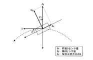
旋回時の車体に作用する遠心力(以下、『場の力』と称す)は、旋回中心から外側に向かって働く。したがって、図3に示すように、旋回を行う車両が横すべり角βを持って走行しているならば、車体に働く『場の力』も当然、車体の真横方向から横すべり角分ずれた方向に発生する。β=β2となることは、幾何学的にも明らかである。そこで、この『場の力』のずれ分β2を、Atan(Gy/Gx)を用いて算出することで、オブザーバの推定を補償するために用いる応用横すべり角として算出する。具体的な計算は、下記の通りである。
Next, the
Centrifugal force (hereinafter referred to as “field force”) acting on the vehicle body during turning works outward from the turning center. Therefore, as shown in FIG. 3, if the vehicle that makes a turn is traveling with a side slip angle β, the “field force” acting on the vehicle body is naturally shifted in the direction shifted by the side slip angle from the lateral direction of the vehicle body. appear. It is also apparent geometrically that β = β 2 . Therefore, the difference field β 2 of the “field force” is calculated using Atan (Gy / Gx), thereby calculating the applied side slip angle used for compensating the observer estimation. The specific calculation is as follows.
図4は、さらに速度変化も考慮した力の釣り合いを示す。旋回による『場の力』と、加減速による『場の力』は、センシングした検出値からその方向の速度変化分を減算することで、旋回によるもののみを抽出することができ、図3の場合と同様に考えることができる。したがって、推定補償器では、以下の計算処理が行われる。ここで、横速度Vyは、車速と推定した横すべり角βの値から幾何学的に(tanβを用いて)算出する。 FIG. 4 shows a balance of forces in consideration of speed change. The “field force” due to turning and the “field force” due to acceleration / deceleration can be extracted by subtracting the speed change in the direction from the sensed detection value, as shown in FIG. You can think in the same way. Accordingly, the following calculation process is performed in the estimation compensator. Here, the lateral speed Vy is calculated geometrically (using tan β) from the value of the side slip angle β estimated as the vehicle speed.
上式で計算した応用横すべり角β2と、オブザーバで推定した横すべり角βの偏差をオブザーバ内の積分器の手前にフィードバックする。この補正をかけるためのフィードバックゲインK2は、図5の制御マップに従って算出する。この制御マップは、横軸に横加速度Gy、縦軸にゲインK2をとり、横加速度Gyが0近傍の所定値以下の場合にはそのゲインK2を0とし、ある程度の横加速度Gy(例えば0.1G)が発生したら、それ以降は発生した横加速度Gyに比例してフィードバックゲインK2を上げていき、所定値(例えば0.5G)以上の横加速度Gyが発生したら、制御の安定するゲイン値で一定とするように設定されている。 The deviation of the applied side slip angle β 2 calculated by the above equation and the side slip angle β estimated by the observer is fed back before the integrator in the observer. The feedback gain K2 for applying this correction is calculated according to the control map of FIG. This control map has a lateral acceleration Gy on the horizontal axis and a gain K2 on the vertical axis. When the lateral acceleration Gy is equal to or less than a predetermined value near 0, the gain K2 is set to 0, and a certain amount of lateral acceleration Gy (for example, 0. 0). 1G), the feedback gain K2 is increased in proportion to the generated lateral acceleration Gy, and when a lateral acceleration Gy of a predetermined value (for example, 0.5G) or more is generated, the gain value becomes stable. It is set to be constant.
《作用》
次に、第1実施形態の作用について説明する。
一般的な線形オブザーバは、車両モデル設計時に想定した路面状況でタイヤの横すべり角が非線形特性とはならない線形領域においては、正確な横すべり角βの推定を行うことができる。しかしながら、路面摩擦係数μが変化したり、旋回性能の限界に近づいたりしたときには、図6に示すように、オブザーバによる推定値が、計測値から徐々に逸脱してしまい、推定精度が低下してしまう。
<Action>
Next, the operation of the first embodiment will be described.
A general linear observer can accurately estimate the side slip angle β in a linear region where the tire side slip angle does not become a nonlinear characteristic under the road surface condition assumed at the time of vehicle model design. However, when the road surface friction coefficient μ changes or approaches the limit of turning performance, the estimated value by the observer gradually deviates from the measured value as shown in FIG. End up.
ところで、幾何学的には、旋回時に車体に作用する『場の力』の方向と左右方向とでなす角度β2は、走行条件に係らず、つまり走行状態が旋回性能の限界に近づいていても、車体の前後方向と進行方向とでなす横すべり角βと一致する。
そこで、図2に示すように、推定した横すべり角βと算出した応用横すべり角β2との差分に応じて、積分器21による積分演算に対してフィードバック補償を行う。これにより、積分演算に伴うエラーの累積などに起因した推定誤差が随時修正されるので、図6に示すように、推定値が計測値に近似する。
By the way, geometrically, the angle β 2 formed between the direction of the “field force” acting on the vehicle body when turning and the left-right direction is independent of the driving conditions, that is, the driving state is approaching the limit of the turning performance. Is also coincident with the side slip angle β formed by the longitudinal direction of the vehicle body and the traveling direction.
Therefore, as shown in FIG. 2, feedback compensation is performed on the integration calculation by the integrator 21 in accordance with the difference between the estimated side slip angle β and the calculated applied side slip angle β 2 . As a result, the estimation error caused by the accumulation of errors accompanying the integration calculation is corrected as needed, so that the estimated value approximates the measured value as shown in FIG.
なお、定速運動していれば、数3に従って、加速度Gx及びGyだけに応じて『場の力』の方向を算出できるが、通常は車速変化を伴うので、精度を向上させるために、数4に従って、車速の変化量も加味して『場の力』の方向を算出する。
また、『場の力』に着目しているので、当然、応用横すべり角β2の算出精度は、『場の力』の発生度合に依存しており、略直進走行しているときや横加速度Gyやヨーレートが低い緩旋回領域では、その精度が低下してしまう。このとき、オブザーバで推定する横すべり角βは、モデル化誤差が小さくなる分、精度が高くなる。そこで、車両の旋回走行状態に応じてフィードバック補償の重みを変化させることで、オブザーバによる推定と推定補償器20によるフィードバック補償との双方の利点を生かして協調させる。具体的には、旋回走行状態が旋回性能の限界に近づくほど、ここでは横加速度Gyが大きくなるほど、フィードバックゲインK2を増加させることで、フィードバック補償の重みを増加させる。
If the vehicle is moving at a constant speed, the direction of the “field force” can be calculated according to only the accelerations Gx and Gy according to
In addition, since we are focusing on “field force”, naturally, the accuracy of calculating the applied side slip angle β 2 depends on the degree of occurrence of “field force”. In the slow turning region where Gy and yaw rate are low, the accuracy is lowered. At this time, the side slip angle β estimated by the observer increases in accuracy because the modeling error decreases. Therefore, by changing the weight of feedback compensation in accordance with the turning state of the vehicle, the advantages of both the estimation by the observer and the feedback compensation by the
また、数3又は数4のAtanにてゼロ割りが発生すると、値は発散してしまい適切なフィードバック補償を行うことができなくなってしまう。そこで、ゼロ割りが発生し得るような『場の力』の弱い非旋回領域では、推定補償器20によるフィードバック補償を中止する。具体的には、横加速度Gyが0近傍の所定値以下にあるようなときには、フィードバックゲインK2を0にする。
また、同様の理由で、ゼロ割りが発生し得るような『場の力』の弱い非旋回領域では、応用横すべり角β2の値を0としてもよい。
In addition, if zero division occurs in Atan of
For the same reason, the value of the applied side slip angle β 2 may be set to 0 in the non-turning region where the “field force” is weak so that the division by zero can occur.
《応用例》
上記の第1実施形態では、横加速度Gyに応じてフィードバックゲインK2の値を変化させているが、これに限定されるものではなく、要は、車両の旋回走行状態に変化させることができればよいので、ヨーレートに応じて変化させてもよい。
また、上記の第1実施形態では、オブザーバによって横すべり角βを推定すると共に、推定補償器20によって応用横すべり角β2を算出し、推定した横すべり角βと算出した応用横すべり角β2との偏差に応じてオブザーバが有する積分器21による積分演算に対してフィードバック補償を行っているが、これに限定されるものではない。すなわち、推定補償器20だけでも応用横すべり角β2を算出できるので、このβ2をそのまま横すべり角βとして推定してもよい。但し、実際の車両にこの手法を採用すると、センサノイズに敏感なため、そのまま推定器として用いるのは現実的ではなく、センシングした検出値にフィルタをかける等して、ノイズを除去することが望ましい。
《Application example》
In the first embodiment described above, the value of the feedback gain K2 is changed according to the lateral acceleration Gy. However, the present invention is not limited to this, and it suffices as long as it can be changed to the turning traveling state of the vehicle. Therefore, it may be changed according to the yaw rate.
In the first embodiment, the side slip angle β is estimated by the observer, the applied side slip angle β 2 is calculated by the
《効果》
以上より、図2のオブザーバが「推定手段」に対応し、横加速度センサ14及び前後加速度センサ15が「加速度検出手段」に対応し、推定補償器20による数3及び数4の演算処理が「算出処理」に対応し、推定補償器20が「補償手段」に対応する。
(1)走行状態を助変数とする積分演算を経て、車体の前後方向と進行方向とでなす横すべり角βを推定する推定手段と、異なる2方向への車体の加速度を検出する加速度検出手段と、この加速度検出手段で検出した車体の加速度に応じて、旋回時の車体に作用する遠心力の方向と車体の左右方向とでなす応用横すべり角β2を算出する算出手段と、推定手段で推定した横すべり角βと算出手段で算出した応用横すべり角β2との偏差に応じて推定手段の積分演算に対するフィードバック補償を行う補償手段と、を備える。
これにより、積分演算に伴うエラーの累積などに起因した推定誤差を修正することができるので、簡単な構成で容易に、しかも高精度に横すべり角βを推定することができる。
"effect"
From the above, the observer in FIG. 2 corresponds to the “estimating means”, the lateral acceleration sensor 14 and the
(1) Estimating means for estimating a side slip angle β between the longitudinal direction and the traveling direction of the vehicle body through integration calculation with the running state as an auxiliary variable, and acceleration detecting means for detecting the acceleration of the vehicle body in two different directions The calculation means for calculating the applied side slip angle β 2 between the direction of the centrifugal force acting on the vehicle body when turning and the lateral direction of the vehicle body according to the acceleration of the vehicle body detected by the acceleration detection means, and the estimation means Compensation means for performing feedback compensation for the integral calculation of the estimation means according to the deviation between the calculated side slip angle β and the applied side slip angle β 2 calculated by the calculation means.
This makes it possible to correct the estimation error caused by the accumulation of errors accompanying the integration calculation, and the side slip angle β can be estimated easily with a simple configuration and with high accuracy.
(2)車速の変化量と加速度検出手段で検出した車体の加速度とに応じて、旋回時の車体に作用する遠心力の方向と車体の左右方向とでなす応用横すべり角β2を算出する。
これにより、車速変化を伴う走行状態であっても、遠心力の方向と車体の左右方向とでなす応用横すべり角β2を正確に算出することができる。
(3)車両の旋回走行状態に応じて、フィードバック補償の重みを変化させる。
これにより、横すべり角βの推定とフィードバック補償との双方の利点を生かした協調作用を得られるので、システム全体として精度の高い横すべり角βを推定することができる。
(2) The applied side slip angle β 2 formed by the direction of the centrifugal force acting on the vehicle body at the time of turning and the left-right direction of the vehicle body is calculated according to the change amount of the vehicle speed and the acceleration of the vehicle body detected by the acceleration detecting means.
As a result, the applied side slip angle β 2 formed between the direction of the centrifugal force and the left-right direction of the vehicle body can be accurately calculated even in a traveling state with a change in vehicle speed.
(3) The weight of feedback compensation is changed according to the turning state of the vehicle.
As a result, it is possible to obtain a cooperative action that takes advantage of both the estimation of the side slip angle β and the feedback compensation, and therefore it is possible to estimate the side slip angle β with high accuracy as the entire system.
(4)車両の旋回走行状態が旋回性能の限界に近づくほど、フィードバック補償の重みを増加させる。
これにより、横すべり角βの推定とフィードバック補償との双方の利点を生かした協調作用を確実に得られるので、システム全体として精度の高い横すべり角βを推定することができる。
(5)車両の旋回走行状態が非旋回領域にあるときにはフィードバック補償を中止する。
これにより、数3又は数4のAtanにてゼロ割りが発生して適切なフィードバック補償を行うことができないといった事態を回避し、推定精度への悪影響を防止することができる。
(4) The weight of feedback compensation is increased as the turning state of the vehicle approaches the limit of turning performance.
As a result, it is possible to reliably obtain a cooperative action that takes advantage of both the estimation of the side slip angle β and the feedback compensation, and therefore it is possible to estimate the side slip angle β with high accuracy as the entire system.
(5) When the turning state of the vehicle is in the non-turning region, feedback compensation is stopped.
As a result, it is possible to avoid a situation in which zero division occurs in Atan of
(6)車両の旋回走行状態が非旋回領域にあるときには応用横すべり角β2を0にする。
これによっても、数3又は数4のAtanにてゼロ割りが発生して適切なフィードバック補償を行うことができないといった事態を回避し、推定精度への悪影響を防止することができる。すなわち、推定した横すべり角βのドリフトや振動を抑制することができる。
(7)異なる2方向への車体の加速度を検出する加速度検出手段と、この加速度検出手段で検出した車体の加速度に応じて、旋回時の車体に作用する遠心力の方向と車体の左右方向とでなす応用横すべり角β2を算出し、算出した応用横すべり角β2を、車体の前後方向と進行方向とでなす横すべり角βとして算出する算出手段と、を備える。
(6) The applied side slip angle β 2 is set to 0 when the turning state of the vehicle is in the non-turning region.
This also avoids a situation in which zero division occurs in Atan of
(7) Acceleration detection means for detecting the acceleration of the vehicle body in two different directions, and the direction of the centrifugal force acting on the vehicle body during turning and the left-right direction of the vehicle body according to the acceleration of the vehicle body detected by the acceleration detection means And calculating means for calculating the calculated side slip angle β 2 formed by the step S 2 and calculating the calculated side slip angle β 2 defined by the front-rear direction and the traveling direction of the vehicle body.
従来の一般的な手法では、横すべり角βの推定には横すべり速度(車体横方向の速度)をいかにして求めるかに着目していたので、加速度センサの検出値を積分するという処理を避けては通れなかった。しかしながら、旋回時における遠心作用の原理に基づいて応用横すべり角β2を算出し、これをそのまま横すべり角βとして算出することで、より簡単な構成で容易に横すべり角βを推定することができ、しかも積分演算に伴うエラーの累積などに起因した推定誤差や、車両モデルにおけるモデル化誤差の心配もないので、高精度に横すべり角βを推定することができる。 In the conventional general method, the side-slip angle β was estimated by focusing on how to determine the side-slip speed (the speed in the lateral direction of the vehicle body), so avoid the process of integrating the detection value of the acceleration sensor. Could not pass. However, by calculating the applied side slip angle β 2 based on the centrifugal action principle at the time of turning, and calculating this as the side slip angle β as it is, the side slip angle β can be easily estimated with a simpler configuration, In addition, there is no estimation error due to accumulation of errors due to integration calculations, or modeling errors in the vehicle model, so the side slip angle β can be estimated with high accuracy.
《第2実施形態》
《構成》
次に、本発明の第2実施形態について説明する。
この第2実施形態は、図7に示すように、主に直接積分法によって横すべり角βを推定するものである。この直接積分法とは、車両横方向の運動の釣り合いにより導かれる次式を積分することで、横すべり角βを求める手法である。
<< Second Embodiment >>
"Constitution"
Next, a second embodiment of the present invention will be described.
In the second embodiment, as shown in FIG. 7, the side slip angle β is estimated mainly by the direct integration method. The direct integration method is a method for obtaining the side slip angle β by integrating the following expression derived from the balance of the movement in the vehicle lateral direction.
そして、この直接積分法を主体にして横すべり角βを推定しつつ、旋回時における遠心作用の原理に基づいて横加速度Gyに対してフィードバック補正を行う第1の補正部31と、線形オブザーバに基づいて積分演算に対してフィードバック補正を行う第2の補正部32と、前述した推定補償器20に基づいて積分演算に対してフィードバック補償を行う補償部33と、を付加している。
先ず、第1の補正部31では、旋回により発生する『場の力』と、横加速度Gy、横すべり角βの関係が次のようになることを補正原理として用いている。
Then, based on the linear observer, the
First, the
![]()
![]()
上記の式に速度Vと、加速度の実測値Gy及びGxと、横すべり角の推定値βとを代入して計算される横加速度Gyと、センシングした横加速度Gyとを比較し、その偏差に応じてフィードバック補正を行う。
次に、第2の補正部32では、図2の推定補償器20を除いたオブザーバによって、直接積分法とは別に横すべり角βを推定し、これら直接積分法による推定値とオブザーバによる推定値との偏差に応じてフィードバック補正を行う。直進状態、又はそれに近い走行パターンにおいては、モデル化誤差の影響が小さいため、線形オブザーバでも十分な精度で横すべり角βを推定できる。そこで、図8に示すように、横加速度Gyとヨーレートが低い非旋回領域では、ゲインK2を大きくし、限界挙動に近づくに連れてゲインK2を下げていく。
The lateral acceleration Gy calculated by substituting the velocity V, the actual measured values Gy and Gx of the acceleration, and the estimated lateral slip angle β into the above formula is compared with the sensed lateral acceleration Gy, and the deviation is determined. To correct the feedback.
Next, in the
そして、補償部33では、前述した第1実施形態と同様に、推定補償器20にてAtan(Gy/Gx)を用いて応用横すべり角β2を算出し、この応用横すべり角β2と直接積分法によって推定した横すべり角βとの偏差と、図5の制御マップに従って設定するゲインK3とに応じてフィードバック補償を行う。
なお、各ゲインK1〜K3の比重、つまり相対的な重みは、車両の旋回走行状態に応じて変化させるものとし、横加速度Gy及びヨーレートが共に低いときには、略直進状態の非旋回領域にあると判断して第2の補正部32のゲインK2を相対的に増加させ、ヨーレートは発生するものの横加速度Gyが弱いときには、緩旋回領域にあると判断して第1の補正部31のゲインK1を相対的に増加させ、これら非旋回領域及び緩旋回領域から外れているときには補償部33のゲインK3を相対的に増加させる。
Then, in the
The specific gravity, that is, the relative weight of each of the gains K1 to K3 is changed according to the turning traveling state of the vehicle. When the gain K2 of the
《作用》
次に、第2実施形態の作用について説明する。
直接積分法は、モデル化誤差の心配がない反面、積分主体の手法であるため誤差が累積するという欠点がある。この解決策として、一般に積分の時定数を調節して誤差の累積量を減らす工夫などがなされているが、何かしらの推定エラーが発生するとしばらくその影響を受け続けてしまったり、長い時間、旋回状態が続くような場合には、蓄積しなくてはならない情報までカットしたりしてしまうため本質的な解決策とは言えない。
<Action>
Next, the operation of the second embodiment will be described.
The direct integration method does not have to worry about modeling errors, but has a drawback that errors accumulate because it is an integration-based method. In general, the solution is to adjust the integration time constant to reduce the cumulative amount of error.However, if some kind of estimation error occurs, it will continue to be affected for a while, or it will turn for a long time. If it continues, the information that must be accumulated will be cut off, which is not an essential solution.
そこで、この第2実施形態では、直接積分法によって推定した横すべり角βに対して、第1の補正部31と、第2の補正部32と、補償部33とで、適宜、最適な補正や補償を行う。
すなわち、略直進状態にあるときには、車両モデルによる線形オブザーバで高精度の横すべり角βを推定することができるので、この第2の補正部32によるフィードバック補正の重みを相対的に増加させる。また、ヨーレートは発生するものの横加速度Gyが弱くて『場の力』を確保しにくい等、ごく短時間のしかも緩い旋回走行状態にあるときには、第1の補正部31によるフィードバック補正の重みを相対的に増加させる。そして、横加速度Gyが増加し『場の力』を確保できる程度の旋回走行状態にあるときには、補償部33によるフィードバック補償の重みを相対的に増加させる。
Therefore, in the second embodiment, the
That is, when the vehicle is in a substantially straight traveling state, the highly accurate side slip angle β can be estimated by a linear observer based on the vehicle model, so the weight of feedback correction by the
《応用例》
上記の第2実施形態では、直接積分法を主体として横すべり角βを推定しつつ、旋回時における遠心作用の原理に基づくフィードバック補正と、線形オブザーバに基づくフィードバック補正と、推定補償器20に基づくフィードバック補償とを行っているが、これに限定されるものではない。すなわち、旋回時における遠心作用の原理に基づくフィードバック補正だけでも十分な効果が得られるので、線形オブザーバに基づくフィードバック補正や推定補償器20に基づくフィードバック補償を省略してもよい。
《Application example》
In the second embodiment described above, the side slip angle β is estimated mainly by the direct integration method, while feedback correction based on the principle of centrifugal action during turning, feedback correction based on a linear observer, and feedback based on the
《効果》
以上より、第1の補正部31が「第1の補正手段」に対応し、第2の補正部32が「第2の補正手段」に対応し、補償部33が「補償手段」に対応する。また、各ゲインK1〜K3の比重を変化させる演算処理が「変更手段」に対応している。
(1)推定手段が直接積分法によって横すべり角βを推定する場合、
旋回時における遠心作用の原理に基づき、推定手段で推定した横すべり角βと加速度検出手段で検出した車体の加速度とに応じて、助変数に対してフィードバック補正を行う第1の補正手段と、車両モデルを利用したオブザーバによって推定手段とは別に横すべり角βを推定し、推定した横すべり角βと推定手段で推定した横すべり角βとの偏差に応じて、この推定手段の積分演算に対してフィードバック補正を行う第2の補正手段と、
補償手段によるフィードバック補償、第1の補正手段によるフィードバック補正、及び第2の補正手段によるフィードバック補正の夫々の相対的な重みを、車両の旋回走行状態に応じて変化させる変更手段と、を備える。
これにより、各種フィードバック補正及びフィードバック補償の利点を生かした協調作用が得られるので、システム全体として精度の高い横すべり角βを推定することができる。
"effect"
From the above, the
(1) When the estimating means estimates the side slip angle β by the direct integration method,
A first correction unit that performs feedback correction on an auxiliary variable according to a side slip angle β estimated by the estimation unit and an acceleration of the vehicle body detected by the acceleration detection unit based on the principle of centrifugal action during turning; The side slip angle β is estimated separately from the estimation means by the observer using the model, and feedback correction is made for the integral calculation of this estimation means according to the deviation between the estimated side slip angle β and the side slip angle β estimated by the estimation means Second correction means for performing
And changing means for changing the relative weights of the feedback compensation by the compensation means, the feedback correction by the first correction means, and the feedback correction by the second correction means in accordance with the turning state of the vehicle.
As a result, a cooperative action utilizing the advantages of various feedback corrections and feedback compensations can be obtained, so that the side slip angle β with high accuracy can be estimated for the entire system.
(2)車両の旋回走行状態が、非旋回領域にあるときには第2の補正手段によるフィードバック補正の重みを相対的に増加させ、緩旋回領域にあるときには第1の補正手段によるフィードバック補正の重みを相対的に増加させ、非旋回領域及び緩旋回領域から外れているときには補償手段によるフィードバック補償の重みを相対的に増加させる。
これにより、各種フィードバック補正及びフィードバック補償の利点を生かした協調作用を確実に得られるので、システム全体として精度の高い横すべり角βを推定することができる。
(2) When the turning state of the vehicle is in the non-turning region, the feedback correction weight by the second correction unit is relatively increased, and when the vehicle is in the slow turning region, the feedback correction weight by the first correction unit is increased. The weight of the feedback compensation by the compensating means is relatively increased when it is relatively increased, and when it is out of the non-turning region and the slow turning region.
As a result, it is possible to reliably obtain a cooperative action utilizing the advantages of various feedback corrections and feedback compensation, and thus it is possible to estimate the side slip angle β with high accuracy as the entire system.
(3)走行状態を助変数とする積分演算を経て、車体の前後方向と進行方向とでなす横すべり角βを推定する推定手段と、異なる2方向への車体の加速度Gy及びGxを検出する加速度検出手段と、旋回時における遠心作用の原理に基づき、推定手段で推定した横すべり角βと加速度検出手段で検出した車体の加速度Gy及びGxとに応じて、助変数としての横加速度Gyに対してフィードバック補正を行う第1の補正手段と、を備える。
これにより、より簡単な構成で容易に、しかも高精度に横すべり角βを推定することができる。さらに、車両モデルにおけるモデル化誤差の心配もない。
(3) Estimating means for estimating the side slip angle β between the longitudinal direction and the traveling direction of the vehicle body through integration calculation with the running state as an auxiliary variable, and acceleration for detecting the vehicle body accelerations Gy and Gx in two different directions Based on the detection means and the side slip angle β estimated by the estimation means based on the principle of centrifugal action during turning and the vehicle body accelerations Gy and Gx detected by the acceleration detection means, the lateral acceleration Gy as an auxiliary variable First correction means for performing feedback correction.
As a result, the side slip angle β can be estimated easily with a simpler configuration and with high accuracy. Furthermore, there is no worry of modeling errors in the vehicle model.
《第3実施形態》
《構成》
次に、本発明の第3実施形態について説明する。
この第3実施形態は、前述した推定補償器20で算出する応用横すべり角β2を、そのまま横すべり角βとして算出するものである。すなわち、次式より横すべり角βを算出する。
<< Third Embodiment >>
"Constitution"
Next, a third embodiment of the present invention will be described.
In the third embodiment, the applied side slip angle β 2 calculated by the
また、図9に示すように、横加速度センサ14と前後加速度センサ15とは別に、車両前後方向に対して±45[deg]ずらした2方向への加速度G1及びG2を検出する加速度センサを備え、横加速度Gy又は前後加速度Gxが所定値以下の場合には、これと±45[deg]ずらして設置された加速度センサの検出値を用いて横すべり角βを算出する。
すなわち、計算方法は上記の式そのままで、算出結果をセンサのずれ角(ここでは、45[deg])分だけ戻せばよい。勿論、本実施形態では±45[deg]のずれ角としたが、このずれ角は任意に設定してよい。
As shown in FIG. 9, in addition to the lateral acceleration sensor 14 and the
That is, the calculation method may be the same as the above formula, and the calculation result may be returned by the sensor shift angle (here, 45 [deg]). Of course, in this embodiment, the deviation angle is ± 45 [deg], but this deviation angle may be set arbitrarily.
《作用》
次に、第3実施形態の作用について説明する。
数7のAtanにてゼロ割りが発生すると、値は発散してしまい横すべり角βを算出することができなくなってしまう。そこで、車両前後方向に対して±45[deg]ずらした2方向への加速度G1及びG2を検出し、これらG1及びG2を用いて横すべり角βを算出する。もし、全ての加速度センサの検出値が所定値以下となる(速度変化があり、加速度センサの検出値から速度変化分を減算したあとの値が所定値以下となる)なら、略直進状態であると判断し、横すべり角βを0にする。なお、一般の車両は、発生する横すべり角βの領域は限られているので、この領域から外れるように2つの加速度センサを設置すれば、常にゼロ割りの発生を回避することができる。
<Action>
Next, the operation of the third embodiment will be described.
When division by zero occurs in Atan of
《効果》
(1)車体の前後方向及び左右方向とは夫々異なる2方向への加速度を検出する。
これにより、数7のAtanにてゼロ割りが発生して横すべり角βを算出することができないといった事態を回避し、確実に横すべり角βをすることができる。
"effect"
(1) Acceleration in two directions different from the front-rear direction and the left-right direction of the vehicle body is detected.
As a result, it is possible to avoid the situation in which zero division occurs in Atan of
《第4実施形態》
《構成》
次に、本発明の第4実施形態について説明する。
この第4実施形態は、ダブルレーンチェンジのように、左右への連続したステアリング操作がなされるときのフィードバック補償の精度を高めるために、前述した第1実施形態におけるフィードバックゲインK2を車両の旋回走行状態に応じて設定するものである。
ここで、フィードバックゲインK2の設定処理を、図10のフローチャートに従って説明する。
<< 4th Embodiment >>
"Constitution"
Next, a fourth embodiment of the present invention will be described.
In the fourth embodiment, in order to improve the accuracy of feedback compensation when the steering operation to the left and right is performed like a double lane change, the feedback gain K2 in the first embodiment described above is used to turn the vehicle. It is set according to the state.
Here, the setting process of the feedback gain K2 will be described with reference to the flowchart of FIG.
ステップS1では、横加速度Gyを読込む。
続くステップS2では、前述した図5の制御マップに従って、フィードバックゲインK2を算出する。
続くステップS3では、フィードバックゲインK2が0より大きいか否かを判定する。この判定結果が『K2=0』であるときには、そのままK2を0として所定のメインプログラムに復帰する。一方、判定結果が『K2>0』であるときには、ステップS4に移行する。
In step S1, the lateral acceleration Gy is read.
In the subsequent step S2, the feedback gain K2 is calculated according to the control map of FIG.
In a succeeding step S3, it is determined whether or not the feedback gain K2 is larger than zero. When the determination result is “K2 = 0”, K2 is set to 0 as it is to return to a predetermined main program. On the other hand, when the determination result is “K2> 0”, the process proceeds to step S4.
ステップS4では、ヨーレートγ及び操舵角θを読込む。
続くステップS5では、操舵角θ及び横すべり角βに基づいて、前輪スリップ角βFを算出する。
続くステップS6では、前輪スリップ角βFがヨーレートγと逆方向に発生しているか否かを判定する。ここで、βFがγと同方向に発生しているときには、車体に作用する遠心力が発生していると判断して、そのままK2を設定して所定のメインプログラムに復帰する。一方、βFがγと逆方向に発生しているときには、車体に作用する遠心力が一時的に消失すると判断してステップS7に移行する。
In step S4, the yaw rate γ and the steering angle θ are read.
In the subsequent step S5, the front wheel slip angle β F is calculated based on the steering angle θ and the side slip angle β.
In a succeeding step S6, it is determined whether or not the front wheel slip angle β F is generated in the direction opposite to the yaw rate γ. Here, when β F is generated in the same direction as γ, it is determined that a centrifugal force acting on the vehicle body is generated, and K2 is set as it is to return to a predetermined main program. On the other hand, when β F is generated in the opposite direction to γ, it is determined that the centrifugal force acting on the vehicle body is temporarily lost, and the process proceeds to step S7.
ステップS7では、フィードバックゲインK2を0に補正する。
続くステップS8では、前輪スリップ角βFが横加速度Gyと同方向に発生したか否かを判定する。ここで、βFがGyと逆方向に発生しているときには、車体に作用する遠心力は再発生していないと判断して、上記ステップS7に戻り、車体に作用する遠心力が再発生するまでK2=0を維持する。一方、βFがGyと同方向に発生しているときには、車体に作用する遠心力が再発生すると判断して所定のメインプログラムに復帰する。
In step S7, the feedback gain K2 is corrected to zero.
In a succeeding step S8, it is determined whether or not the front wheel slip angle β F is generated in the same direction as the lateral acceleration Gy. Here, when β F is generated in the direction opposite to Gy, it is determined that the centrifugal force acting on the vehicle body is not regenerated, and the process returns to step S7 to regenerate the centrifugal force acting on the vehicle body. Until K2 = 0. On the other hand, when β F is generated in the same direction as Gy, it is determined that the centrifugal force acting on the vehicle body is regenerated, and the routine returns to a predetermined main program.
《作用》
次に、第4実施形態の作用について説明する。
図11に示すように、車線変更時のダブルレーンチェンジのように、左右への連続したステアリング操作がなされると、旋回方向が一方から他方へ切換わる瞬間に、横すべり角βが残っているのに(|β|>0)、車体に作用する遠心力が一時的に消失するという現象が起こる。したがって、この遠心力が消失している間は、応用横すべり角β2を高精度に算出することができないので、フィードバック補償に影響を及ぼしてしまう。
<Action>
Next, the operation of the fourth embodiment will be described.
As shown in FIG. 11, when the steering operation is continued to the left and right as in a double lane change at the time of lane change, the side slip angle β remains at the moment when the turning direction is switched from one to the other. (| Β |> 0), a phenomenon occurs in which the centrifugal force acting on the vehicle body temporarily disappears. Therefore, while the centrifugal force disappears, the applied side slip angle β 2 cannot be calculated with high accuracy, which affects feedback compensation.
そこで、車体に作用する遠心力が一時的に消失すると判断したら(ステップS6の判定が“Yes”)、遠心力が再発生するまでの間は、フィードバックゲインK2を0に制限して(ステップS7)、フィードバック補償への影響を回避する。
遠心力の消失は、ヨーレートγと逆方向の前輪スリップ角βFが発生するか否かに基づいて判断する。このように、旋回方向と前輪スリップ角βFの発生方向とを比較することで、ドリフト走行を行うときのカウンターステアと、ダブルレーンチェンジを行うときのステアリング操作とを区別して、遠心力の消失を正確に予測する。すなわち、旋回方向と前輪スリップ角βFの発生方向とが一致するドリフト走行では、遠心力は消失しないからである。
Therefore, if it is determined that the centrifugal force acting on the vehicle body is temporarily lost (“Yes” in step S6), the feedback gain K2 is limited to 0 until the centrifugal force is regenerated (step S7). ) To avoid impact on feedback compensation.
The disappearance of the centrifugal force is determined based on whether or not a front wheel slip angle β F in the direction opposite to the yaw rate γ occurs. In this way, by comparing the turning direction and the direction in which the front wheel slip angle β F is generated, it is possible to distinguish the counter steer when performing drift driving from the steering operation when performing double lane change, and the disappearance of centrifugal force Predict accurately. That is, the centrifugal force does not disappear in the drift traveling in which the turning direction and the generation direction of the front wheel slip angle β F coincide with each other.
その後、遠心力が復活する、つまり再発生すると判断したら(ステップS8の判定が“Yes”)、フィードバックゲインK2に対する制限を解除して、通常のフィードバック補償を再開する。遠心力の再発生は、前輪スリップ角βFと同方向の横加速度Gyが発生するか否かに基づいて判断する。 Thereafter, when it is determined that the centrifugal force is restored, that is, is regenerated (the determination in step S8 is “Yes”), the restriction on the feedback gain K2 is released, and normal feedback compensation is resumed. The re-generation of the centrifugal force is determined based on whether or not the lateral acceleration Gy in the same direction as the front wheel slip angle β F is generated.
《応用例》
上記の第4実施形態では、遠心力が再発生するまでの間は、フィードバックゲインK2を0に制限しているが、遠心力が消失すると判断した時点から所定時間が経過するまで、フィードバックゲインK2を制限するようにしてもよい。すなわち、ステアリング操作に対する車両挙動の応答時間は、各車両の諸元によって定まるので、少なくともこの応答時間が経過するまで、フィードバックゲインK2を制限すればよい。これによれば、容易に前述した作用効果を得ることができる。
《Application example》
In the fourth embodiment, the feedback gain K2 is limited to 0 until the centrifugal force is regenerated. However, the feedback gain K2 is maintained until a predetermined time elapses after it is determined that the centrifugal force disappears. You may make it restrict | limit. That is, the response time of the vehicle behavior with respect to the steering operation is determined by the specifications of each vehicle. Therefore, the feedback gain K2 may be limited at least until the response time elapses. According to this, the effect mentioned above can be obtained easily.
また、上記の第4実施形態では、旋回方向と逆方向の前輪スリップ角βFを検知したときに、遠心力が一時的に消失すると判断しているが、旋回方向と逆方向の操舵角θを検知したときに、遠心力が一時的に消失すると判断してもよい。すなわち、旋回方向と逆方向のステアリング操作がなされ、且つ操舵角θが中立位置を越えれば、車体を回頭させるモーメントが減少し、この後に遠心力が一時的に消失するからである。これによれば、容易に前述した作用効果を得ることができる。 In the fourth embodiment, when the front wheel slip angle β F in the direction opposite to the turning direction is detected, it is determined that the centrifugal force temporarily disappears. However, the steering angle θ in the direction opposite to the turning direction is determined. It may be determined that the centrifugal force temporarily disappears when That is, if the steering operation in the direction opposite to the turning direction is performed and the steering angle θ exceeds the neutral position, the moment for turning the vehicle body decreases, and thereafter the centrifugal force temporarily disappears. According to this, the effect mentioned above can be obtained easily.
また、上記の第4実施形態では、一旦、旋回方向と逆方向の前輪スリップ角βFを検知したら、遠心力が再発生するまでの間は、フィードバックゲインK2を制限しているが、旋回方向が一方から他方へ移行する前に、一方への操舵角に復帰したときには、直ちにフィードバックゲインK2の制限を解除してもよい。すなわち、元の旋回方向へのステアリング操作に戻れば、遠心力は消失することなく、それまでの旋回軌跡を描き続けることになるので、フィードバックゲインK2を制限する必要はなくなるからである。 In the fourth embodiment, once the front wheel slip angle β F in the direction opposite to the turning direction is detected, the feedback gain K2 is limited until the centrifugal force is regenerated. When the steering angle returns to one before moving from one to the other, the restriction on the feedback gain K2 may be immediately released. That is, when returning to the steering operation in the original turning direction, the centrifugal force is not lost, and the previous turning trajectory is continuously drawn. Therefore, it is not necessary to limit the feedback gain K2.
また、上記の第4実施形態では、フィードバックゲインK2を制限したり、これを解除したりする際に、そのままK2を変化させているが、K2の変化速度(所定時間毎の変化量)を抑制するようにしてもよい。すなわち、K2が急変すると、フィードバック補償に影響を及ぼし得るので、所定のフィルタ処理によって滑らかに変化させることで、過敏な応答を防止した望ましいフィードバック補償を実現できる。 In the fourth embodiment, when the feedback gain K2 is limited or released, K2 is changed as it is, but the change rate of K2 (change amount per predetermined time) is suppressed. You may make it do. That is, when K2 changes suddenly, feedback compensation can be affected. Therefore, it is possible to realize desired feedback compensation that prevents a sensitive response by smoothly changing the value by a predetermined filter process.
また、上記の第4実施形態では、前述した第1実施形態におけるフィードバックゲインK2を車両の旋回走行状態に応じて設定しているが、勿論、前述した第2実施形態におけるフィードバックゲインK3に適用してもよい。これによれば、当然、第2実施形態の作用効果を合わせて得ることができる。 In the fourth embodiment, the feedback gain K2 in the first embodiment described above is set according to the turning state of the vehicle. Of course, the feedback gain K3 in the second embodiment described above is applied. May be. According to this, naturally, the operation and effect of the second embodiment can be obtained together.
《効果》
以上より、図10のゲイン設定処理が「補償手段」の一部を構成している。
(1)補償手段は、車体に作用する遠心力が、車両の旋回走行状態に応じて一時的に消失すると判断したときには、当該遠心力が再発生するまで、フィードバック補償の重みを制限する。
これにより、ダブルレーンチェンジのような左右へ連続したステアリング操作がなされて、遠心力が一時的に消失するような場合に、応用横すべり角β2の誤算によってフィードバック補償の精度が低下する、といった事態を回避することができる。
"effect"
As described above, the gain setting process in FIG. 10 constitutes a part of the “compensation means”.
(1) When it is determined that the centrifugal force acting on the vehicle body temporarily disappears according to the turning traveling state of the vehicle, the compensation unit limits the weight of feedback compensation until the centrifugal force is regenerated.
As a result, when the steering operation is continued to the left and right, such as a double lane change, and the centrifugal force temporarily disappears, the accuracy of feedback compensation decreases due to miscalculation of the applied side slip angle β 2 Can be avoided.
(2)補償手段は、車体に作用する遠心力が、車両の旋回走行状態に応じて一時的に消失すると判断したときには、当該遠心力が消失すると判断した時点から所定時間が経過するまで、フィードバック補償の重みを制限する。
これによれば、遠心力の再発生を検出しなくとも、単に経過時間を計測していればよいので、容易に上記の作用効果を得ることができる。
(3)補償手段は、旋回方向と逆方向の操舵角を検知したときに、車体に作用する遠心力が一時的に消失すると判断する。
これによれば、前輪スリップ角βFを演算しなくとも、単に操舵角θを検出していればよいので、容易に上記の作用効果を得ることができる。
(2) When it is determined that the centrifugal force acting on the vehicle body temporarily disappears according to the turning traveling state of the vehicle, the compensating means performs feedback until a predetermined time elapses from the time when the centrifugal force is determined to disappear. Limit the weight of compensation.
According to this, even if it is not necessary to detect the reoccurrence of the centrifugal force, it is only necessary to measure the elapsed time, and thus the above-described effects can be easily obtained.
(3) The compensation means determines that the centrifugal force acting on the vehicle body temporarily disappears when the steering angle in the direction opposite to the turning direction is detected.
According to this, since it is only necessary to detect the steering angle θ without calculating the front wheel slip angle β F , the above-described effects can be obtained easily.
(4)補償手段は、旋回方向と逆方向の操舵輪スリップ角を検知したときに、車体に作用する遠心力が一時的に消失すると判断する。
これにより、ドリフト走行を行うときのカウンターステアと、ダブルレーンチェンジを行うときのステアリング操作とを区別して、遠心力の消失を正確に予測することができる。
(5)補償手段は、旋回方向と同方向の横加速度を検知したときに、遠心力が再発生すると判断する。
これにより、遠心力の再発生を容易に且つ確実に判断することができる。
(4) The compensation means determines that the centrifugal force acting on the vehicle body temporarily disappears when the steering wheel slip angle in the direction opposite to the turning direction is detected.
Thus, it is possible to accurately predict the disappearance of the centrifugal force by distinguishing between the counter steer when performing the drift traveling and the steering operation when performing the double lane change.
(5) The compensating means determines that the centrifugal force is regenerated when a lateral acceleration in the same direction as the turning direction is detected.
Thereby, it is possible to easily and reliably determine whether the centrifugal force is regenerated.
(6)補償手段は、旋回方向が一方から他方へ移行する前に、一方への操舵角に復帰したときには、フィードバック補償の重みに対する制限を解除する。
これによれば、フィードバック補償の重みに対する不必要な制限を中止し、適切なタイミングで通常のフィードバック補償に復帰することができる。
(7)補償手段は、フィードバック補償の重みの変化速度を抑制する。
これによれば、フィードバック補償の重みを滑らかに変化させることができるので、過敏な応答を防止した望ましいフィードバック補償を実現することができる。
(6) When the turning direction returns to the steering angle to one side before the turning direction shifts from one to the other, the compensation unit releases the restriction on the weight of the feedback compensation.
According to this, it is possible to cancel unnecessary restriction on the weight of feedback compensation and return to normal feedback compensation at an appropriate timing.
(7) The compensation means suppresses the rate of change of the weight of feedback compensation.
According to this, since the weight of feedback compensation can be changed smoothly, it is possible to realize desirable feedback compensation that prevents a sensitive response.
1 自動車
2 コントローラ
3FL・3FR 前輪
4 タイロッド
5 ラック&ピニオン
6 ステアリングシャフト
7 ステアリングホイール
11 舵角センサ
12 車速センサ
13 ヨーレートセンサ
14 横加速度センサ
15 前後加速度センサ
20 推定補償器
DESCRIPTION OF
Claims (18)
旋回時における遠心作用の原理に基づき、前記推定手段で推定した横すべり角と前記加速度検出手段で検出した車体の加速度とに応じて、前記助変数の横加速度に対してフィードバック補正を行う第1の補正手段と、車両モデルを利用したオブザーバによって前記推定手段とは別に前記横すべり角を推定し、推定した横すべり角と前記推定手段で推定した横すべり角との偏差に応じて、当該推定手段の積分演算に対してフィードバック補正を行う第2の補正手段と、
ヨーレート及び横加速度を車両の旋回走行状態として入力し、前記補償手段によるフィードバック補償、前記第1の補正手段によるフィードバック補正、及び前記第2の補正手段によるフィードバック補正の夫々の相対的な重みを、前記旋回走行状態のヨーレート及び横加速度に応じて変化させる変更手段と、を備え、
前記第1の補正手段は、次式によって算出した横加速度と前記助変数の横加速度との偏差に応じて、前記助変数の横加速度に対してフィードバック補正を行うことを特徴とする請求項1〜13の何れか一項に記載の横すべり角推定装置。
Based on the principle of centrifugal action during turning, a first feedback correction is performed for the lateral acceleration of the auxiliary variable according to the side slip angle estimated by the estimating means and the acceleration of the vehicle body detected by the acceleration detecting means. The side slip angle is estimated separately from the estimation means by a correction means and an observer using a vehicle model, and an integral operation of the estimation means is performed according to a deviation between the estimated side slip angle and the side slip angle estimated by the estimation means. Second correction means for performing feedback correction for
The yaw rate and the lateral acceleration are input as the turning state of the vehicle , and the respective relative weights of the feedback compensation by the compensation means, the feedback correction by the first correction means, and the feedback correction by the second correction means are as follows: and a changing means for changing in accordance with the yaw rate and lateral acceleration of the turning traveling state,
2. The first correction means performs feedback correction on the lateral acceleration of the auxiliary variable in accordance with a deviation between the lateral acceleration calculated by the following equation and the lateral acceleration of the auxiliary variable. The side slip angle estimating device according to any one of ˜13.
前記横すべり角推定装置は、
操舵角、車速、ヨーレート、及び横加速度を走行状態として入力し、前記走行状態を助変数とする積分演算を経て、車体の前後方向と進行方向とでなす横すべり角を推定する推定手段と、異なる2方向への車体の加速度を検出する加速度検出手段と、該加速度検出手段で検出した車体の加速度に応じて、旋回時の車体に作用する遠心力の方向と車体の左右方向とでなす応用横すべり角を算出する算出手段と、前記推定手段で推定した横すべり角と前記算出手段で算出した応用横すべり角との偏差に応じて前記推定手段の積分演算に対するフィードバック補償を行う補償手段と、を備えることを特徴とする自動車。 In a car equipped with a side slip angle estimation device,
The side slip angle estimating device is:
Different from the estimation means that inputs the steering angle, vehicle speed, yaw rate, and lateral acceleration as the running state and estimates the side slip angle between the longitudinal direction and the traveling direction of the vehicle body through integration calculation using the running state as an auxiliary variable. Acceleration detection means for detecting the acceleration of the vehicle body in two directions, and applied lateral slip between the direction of the centrifugal force acting on the vehicle body during turning and the left-right direction of the vehicle body in accordance with the acceleration of the vehicle body detected by the acceleration detection means A calculating means for calculating an angle; and a compensating means for performing feedback compensation for the integral operation of the estimating means in accordance with a deviation between a side slip angle estimated by the estimating means and an applied side slip angle calculated by the calculating means. A car characterized by
Priority Applications (4)
| Application Number | Priority Date | Filing Date | Title |
|---|---|---|---|
| JP2006199450A JP5011866B2 (en) | 2006-01-23 | 2006-07-21 | Side slip angle estimation device, automobile, and side slip angle estimation method |
| US11/656,282 US7844383B2 (en) | 2006-01-23 | 2007-01-22 | Sideslip angle estimation apparatus and method and automotive vehicle incorporating the same |
| EP07100945.0A EP1811308B1 (en) | 2006-01-23 | 2007-01-22 | Apparatus and method for estimating a sideslip angle |
| CN2007100036357A CN101007530B (en) | 2006-01-23 | 2007-01-23 | Apparatus and method for estimating a sideslip angle, automobile |
Applications Claiming Priority (3)
| Application Number | Priority Date | Filing Date | Title |
|---|---|---|---|
| JP2006013676 | 2006-01-23 | ||
| JP2006013676 | 2006-01-23 | ||
| JP2006199450A JP5011866B2 (en) | 2006-01-23 | 2006-07-21 | Side slip angle estimation device, automobile, and side slip angle estimation method |
Publications (2)
| Publication Number | Publication Date |
|---|---|
| JP2007216942A JP2007216942A (en) | 2007-08-30 |
| JP5011866B2 true JP5011866B2 (en) | 2012-08-29 |
Family
ID=37964778
Family Applications (1)
| Application Number | Title | Priority Date | Filing Date |
|---|---|---|---|
| JP2006199450A Expired - Fee Related JP5011866B2 (en) | 2006-01-23 | 2006-07-21 | Side slip angle estimation device, automobile, and side slip angle estimation method |
Country Status (4)
| Country | Link |
|---|---|
| US (1) | US7844383B2 (en) |
| EP (1) | EP1811308B1 (en) |
| JP (1) | JP5011866B2 (en) |
| CN (1) | CN101007530B (en) |
Families Citing this family (16)
| Publication number | Priority date | Publication date | Assignee | Title |
|---|---|---|---|---|
| JP5103629B2 (en) * | 2006-02-07 | 2012-12-19 | 国立大学法人東京農工大学 | Vehicle operation measuring device and vehicle abnormal operation preventing device |
| US7885750B2 (en) * | 2006-08-30 | 2011-02-08 | Ford Global Technologies | Integrated control system for stability control of yaw, roll and lateral motion of a driving vehicle using an integrated sensing system to determine a sideslip angle |
| JP5062010B2 (en) * | 2008-04-11 | 2012-10-31 | 日本精工株式会社 | Electric power steering device |
| US7657395B2 (en) * | 2008-07-07 | 2010-02-02 | Memsic Inc. | Two-axis accelerometer for detecting inclination without the effect of common acceleration |
| JP5402244B2 (en) * | 2009-05-26 | 2014-01-29 | トヨタ自動車株式会社 | Vehicle physical quantity estimation device |
| US10102706B2 (en) | 2011-08-23 | 2018-10-16 | Vendrx, Inc. | Beneficial product dispenser |
| US8977390B2 (en) | 2011-08-23 | 2015-03-10 | Vendrx, Inc. | Systems and methods for dispensing beneficial products |
| KR101962890B1 (en) * | 2012-03-02 | 2019-08-01 | 현대모비스 주식회사 | System and method for compensating vehicle sensor's offset |
| US9878738B2 (en) | 2012-03-28 | 2018-01-30 | Robert Bosch Gmbh | Non-linear compensation controller for active steering system in a vehicle |
| JP6010985B2 (en) * | 2012-04-06 | 2016-10-19 | 日産自動車株式会社 | Vehicle system vibration control device |
| JP5973667B2 (en) * | 2013-07-17 | 2016-08-23 | 日立オートモティブシステムズ株式会社 | Vehicle control device |
| EP3246210B1 (en) * | 2016-05-17 | 2018-12-26 | Volvo Car Corporation | System and method for activation of warning lights of a vehicle |
| KR102621533B1 (en) * | 2018-11-26 | 2024-01-05 | 현대자동차주식회사 | Apparatus and method for controlling steering system of vehicle |
| DE102019112900A1 (en) | 2019-05-16 | 2020-11-19 | Wabco Gmbh | Method for determining a slip angle while a motor vehicle is cornering, driver assistance system for carrying out the method and motor vehicle |
| US11702084B2 (en) * | 2019-11-25 | 2023-07-18 | The Goodyear Tire & Rubber Company | Vehicle sideslip angle estimation system and method |
| DE102021100468A1 (en) | 2021-01-13 | 2022-07-14 | Bayerische Motoren Werke Aktiengesellschaft | Determining an attitude angle of a vehicle |
Family Cites Families (42)
| Publication number | Priority date | Publication date | Assignee | Title |
|---|---|---|---|---|
| JPH0725320B2 (en) * | 1986-10-13 | 1995-03-22 | 日産自動車株式会社 | Actual steering angle control device for vehicle |
| JPH0750121B2 (en) * | 1988-04-19 | 1995-05-31 | 日産自動車株式会社 | Vehicle slip angle measuring device |
| JP2844240B2 (en) * | 1990-03-15 | 1999-01-06 | 本田技研工業株式会社 | Automatic traveling device |
| GB2245873B (en) * | 1990-04-18 | 1994-03-16 | Nissan Motor | Control system for optimizing operation of vehicle performance/safety enhancing systems |
| DE4031304A1 (en) | 1990-10-04 | 1992-04-09 | Bosch Gmbh Robert | Model supported estimation of float angle - using vehicle speed from ABS system, steering angle sensor to derive transverse speed and hence float angle |
| JP2817464B2 (en) * | 1991-09-04 | 1998-10-30 | 日産自動車株式会社 | Vehicle rear wheel steering angle control device |
| DE4217710A1 (en) | 1992-06-01 | 1993-12-02 | Porsche Ag | Continuous detection of slippery winter road surfaces - determining and comparing driving parameters and boundary conditions for motor car |
| DE4218034B4 (en) * | 1992-06-02 | 2006-05-24 | Dr.Ing.H.C. F. Porsche Ag | Method for determining the adhesion potential of a motor vehicle |
| US5710705A (en) * | 1994-11-25 | 1998-01-20 | Itt Automotive Europe Gmbh | Method for determining an additional yawing moment based on side slip angle velocity |
| DE19515048A1 (en) * | 1994-11-25 | 1996-05-30 | Teves Gmbh Alfred | Regulator for motor vehicle ABS, ASR, braking force distribution (EBV) and yaw control (GMR) |
| US5732377A (en) * | 1994-11-25 | 1998-03-24 | Itt Automotive Europe Gmbh | Process for controlling driving stability with a yaw rate sensor equipped with two lateral acceleration meters |
| JP3282449B2 (en) * | 1995-06-09 | 2002-05-13 | トヨタ自動車株式会社 | Vehicle skidding state quantity detection device |
| JP2993400B2 (en) * | 1995-06-09 | 1999-12-20 | 三菱自動車工業株式会社 | Vehicle turning control device |
| JPH0911876A (en) * | 1995-06-30 | 1997-01-14 | Mitsubishi Motors Corp | Turning control device of vehicle |
| JP3050092B2 (en) * | 1995-06-30 | 2000-06-05 | 三菱自動車工業株式会社 | Vehicle turning control device |
| JP3633120B2 (en) * | 1996-07-18 | 2005-03-30 | 日産自動車株式会社 | Vehicle speed and road friction coefficient estimation device |
| JP3169213B2 (en) * | 1998-02-27 | 2001-05-21 | 株式会社データ・テック | Moving speed detecting method and device, vehicle slip angle detecting device |
| JP2000233738A (en) * | 1999-02-12 | 2000-08-29 | Toyota Central Res & Dev Lab Inc | Running condition judging device for vehicle |
| JP3650714B2 (en) | 2000-02-08 | 2005-05-25 | 光洋精工株式会社 | Vehicle steering system |
| JP2003531066A (en) * | 2000-04-19 | 2003-10-21 | コンティネンタル・テーベス・アクチエンゲゼルシヤフト・ウント・コンパニー・オッフェネ・ハンデルスゲゼルシヤフト | How to determine the amount of driving dynamics for cars online |
| JP2001334921A (en) * | 2000-05-30 | 2001-12-04 | Fuji Heavy Ind Ltd | Estimating device for surface friction coefficient of vehicle |
| DE10039782A1 (en) * | 2000-08-16 | 2002-02-28 | Daimler Chrysler Ag | Method for regulating yaw and lateral dynamics in a road vehicle |
| US6904350B2 (en) | 2000-09-25 | 2005-06-07 | Ford Global Technologies, Llc | System for dynamically determining the wheel grounding and wheel lifting conditions and their applications in roll stability control |
| JP3236004B1 (en) * | 2000-10-31 | 2001-12-04 | 富士重工業株式会社 | Road surface friction coefficient estimation device for vehicles |
| DE10054647A1 (en) * | 2000-11-03 | 2002-05-08 | Daimler Chrysler Ag | Procedure for regulating driving stability |
| JP3539722B2 (en) * | 2000-11-16 | 2004-07-07 | 富士重工業株式会社 | Road surface friction coefficient estimation device for vehicles |
| JP2003146199A (en) | 2001-11-15 | 2003-05-21 | Honda Motor Co Ltd | Estimation method of vehicle state quantity |
| US6671595B2 (en) * | 2002-01-08 | 2003-12-30 | Ford Global Technologies, Llc | Vehicle side slip angle estimation using dynamic blending and considering vehicle attitude information |
| JP2003306092A (en) * | 2002-04-16 | 2003-10-28 | Honda Motor Co Ltd | Method for estimating vehicle state quantity |
| DE10325485A1 (en) | 2002-06-11 | 2004-01-08 | Continental Teves Ag & Co. Ohg | Determining vehicle float angle involves modeling lateral force component on tire, linearizing relative to skew angle, determining relationship between skew, float angles, using kinetic relationship |
| US6662898B1 (en) * | 2002-10-16 | 2003-12-16 | Ford Global Technologies, Llc | Tire side slip angle control for an automotive vehicle using steering actuators |
| US6840343B2 (en) * | 2002-10-16 | 2005-01-11 | Ford Global Technologies, Llc | Tire side slip angle control for an automotive vehicle using steering peak seeking actuators |
| JP4202872B2 (en) * | 2003-09-12 | 2008-12-24 | 株式会社ジェイテクト | Vehicle steering system |
| JP2005112007A (en) | 2003-10-02 | 2005-04-28 | Toyoda Mach Works Ltd | Vehicular integrated control device |
| JP4369198B2 (en) * | 2003-10-10 | 2009-11-18 | 株式会社ジェイテクト | Vehicle steering control device |
| JP4349309B2 (en) * | 2004-09-27 | 2009-10-21 | 日産自動車株式会社 | Vehicle steering control device |
| US7590481B2 (en) * | 2005-09-19 | 2009-09-15 | Ford Global Technologies, Llc | Integrated vehicle control system using dynamically determined vehicle conditions |
| US7739014B2 (en) * | 2006-08-30 | 2010-06-15 | Ford Global Technolgies | Integrated control system for stability control of yaw, roll and lateral motion of a driving vehicle using an integrated sensing system to determine a final linear lateral velocity |
| US7970512B2 (en) * | 2006-08-30 | 2011-06-28 | Ford Global Technologies | Integrated control system for stability control of yaw, roll and lateral motion of a driving vehicle using an integrated sensing system with pitch information |
| US7885750B2 (en) * | 2006-08-30 | 2011-02-08 | Ford Global Technologies | Integrated control system for stability control of yaw, roll and lateral motion of a driving vehicle using an integrated sensing system to determine a sideslip angle |
| US8321088B2 (en) * | 2006-08-30 | 2012-11-27 | Ford Global Technologies | Integrated control system for stability control of yaw, roll and lateral motion of a driving vehicle using an integrated sensing system to determine lateral velocity |
| US8712639B2 (en) * | 2006-08-30 | 2014-04-29 | Ford Global Technologies | Integrated control system for stability control of yaw, roll and lateral motion of a driving vehicle using an integrated sensing system to determine longitudinal velocity |
-
2006
- 2006-07-21 JP JP2006199450A patent/JP5011866B2/en not_active Expired - Fee Related
-
2007
- 2007-01-22 US US11/656,282 patent/US7844383B2/en active Active
- 2007-01-22 EP EP07100945.0A patent/EP1811308B1/en not_active Expired - Fee Related
- 2007-01-23 CN CN2007100036357A patent/CN101007530B/en not_active Expired - Fee Related
Also Published As
| Publication number | Publication date |
|---|---|
| US20070173997A1 (en) | 2007-07-26 |
| JP2007216942A (en) | 2007-08-30 |
| EP1811308B1 (en) | 2015-12-02 |
| CN101007530B (en) | 2012-06-13 |
| CN101007530A (en) | 2007-08-01 |
| US7844383B2 (en) | 2010-11-30 |
| EP1811308A3 (en) | 2008-07-16 |
| EP1811308A2 (en) | 2007-07-25 |
Similar Documents
| Publication | Publication Date | Title |
|---|---|---|
| JP5011866B2 (en) | Side slip angle estimation device, automobile, and side slip angle estimation method | |
| US6904349B2 (en) | Method of estimating quantities that represent state of vehicle | |
| US20060041365A1 (en) | Estimating method for road friction coefficient and vehicle slip angle estimating method | |
| US20080015754A1 (en) | System for estimating and compensating for lateral disturbances using controlled steering and braking | |
| JPH06104455B2 (en) | Vehicle motion condition estimation device | |
| JPH09118212A (en) | Side slip speed estimating device of car body | |
| JP5029442B2 (en) | Vehicle attitude angle estimation device and program | |
| JP4127062B2 (en) | Lateral acceleration sensor drift amount estimation device, lateral acceleration sensor output correction device, and road surface friction state estimation device | |
| KR20080101738A (en) | Motion control device for vehicle using information added acceleration | |
| JP3800901B2 (en) | Lane tracking control device | |
| US9026334B2 (en) | Vehicle attitude control system | |
| US20010054310A1 (en) | Process for improved determination of the ratio among the radii of the wheels of a vehicle | |
| US7085641B2 (en) | Ackerman angle correction in a steering system for a low speed turn | |
| JP5251177B2 (en) | Vehicle running state estimation device | |
| JP4071529B2 (en) | Self-aligning torque estimation device and lateral grip degree estimation device | |
| JP4887721B2 (en) | Vehicle running state estimation device | |
| JP6428497B2 (en) | Vehicle control device | |
| US20080167777A1 (en) | Method for Controlling the Steering Orientation of a Vehicle | |
| JP3282449B2 (en) | Vehicle skidding state quantity detection device | |
| JP2014108728A (en) | Vehicle body sideslip angle estimation device | |
| JP5251176B2 (en) | Vehicle running state estimation device | |
| JP4211638B2 (en) | Power steering device for vehicle and disturbance estimation device for vehicle | |
| JP5326562B2 (en) | Turning behavior detection device, turning behavior detection method, and yaw rate estimation method | |
| KR100892480B1 (en) | System for presuming self-alignment torque | |
| JP5375088B2 (en) | Turning behavior control device, turning behavior control method |
Legal Events
| Date | Code | Title | Description |
|---|---|---|---|
| A621 | Written request for application examination |
Free format text: JAPANESE INTERMEDIATE CODE: A621 Effective date: 20090326 |
|
| RD04 | Notification of resignation of power of attorney |
Free format text: JAPANESE INTERMEDIATE CODE: A7424 Effective date: 20100917 |
|
| A131 | Notification of reasons for refusal |
Free format text: JAPANESE INTERMEDIATE CODE: A131 Effective date: 20111011 |
|
| TRDD | Decision of grant or rejection written | ||
| A01 | Written decision to grant a patent or to grant a registration (utility model) |
Free format text: JAPANESE INTERMEDIATE CODE: A01 Effective date: 20120508 |
|
| A01 | Written decision to grant a patent or to grant a registration (utility model) |
Free format text: JAPANESE INTERMEDIATE CODE: A01 |
|
| A61 | First payment of annual fees (during grant procedure) |
Free format text: JAPANESE INTERMEDIATE CODE: A61 Effective date: 20120521 |
|
| FPAY | Renewal fee payment (event date is renewal date of database) |
Free format text: PAYMENT UNTIL: 20150615 Year of fee payment: 3 |
|
| R150 | Certificate of patent or registration of utility model |
Free format text: JAPANESE INTERMEDIATE CODE: R150 |
|
| LAPS | Cancellation because of no payment of annual fees |