JP5004849B2 - Communication system, information processing apparatus, and control method - Google Patents
Communication system, information processing apparatus, and control method Download PDFInfo
- Publication number
- JP5004849B2 JP5004849B2 JP2008084099A JP2008084099A JP5004849B2 JP 5004849 B2 JP5004849 B2 JP 5004849B2 JP 2008084099 A JP2008084099 A JP 2008084099A JP 2008084099 A JP2008084099 A JP 2008084099A JP 5004849 B2 JP5004849 B2 JP 5004849B2
- Authority
- JP
- Japan
- Prior art keywords
- network
- information
- communication
- forming
- communication devices
- Prior art date
- Legal status (The legal status is an assumption and is not a legal conclusion. Google has not performed a legal analysis and makes no representation as to the accuracy of the status listed.)
- Expired - Fee Related
Links
- 238000004891 communication Methods 0.000 title claims description 140
- 238000000034 method Methods 0.000 title claims description 26
- 230000010365 information processing Effects 0.000 title claims description 14
- 230000004044 response Effects 0.000 claims description 31
- 230000008034 disappearance Effects 0.000 claims description 22
- 230000008569 process Effects 0.000 claims description 22
- 230000005540 biological transmission Effects 0.000 claims description 20
- 230000015572 biosynthetic process Effects 0.000 claims description 7
- 230000008859 change Effects 0.000 description 78
- 239000002076 α-tocopherol Substances 0.000 description 30
- 235000004835 α-tocopherol Nutrition 0.000 description 30
- 230000006870 function Effects 0.000 description 29
- 238000012508 change request Methods 0.000 description 28
- 238000000926 separation method Methods 0.000 description 23
- 238000010586 diagram Methods 0.000 description 19
- 239000004318 erythorbic acid Substances 0.000 description 15
- 235000010350 erythorbic acid Nutrition 0.000 description 15
- 230000004913 activation Effects 0.000 description 9
- 239000004261 Ascorbyl stearate Substances 0.000 description 6
- 235000019276 ascorbyl stearate Nutrition 0.000 description 6
- 235000010382 gamma-tocopherol Nutrition 0.000 description 5
- 239000002478 γ-tocopherol Substances 0.000 description 5
- 230000008033 biological extinction Effects 0.000 description 4
- 239000004255 Butylated hydroxyanisole Substances 0.000 description 3
- 235000019282 butylated hydroxyanisole Nutrition 0.000 description 3
- 239000000555 dodecyl gallate Substances 0.000 description 3
- 235000010386 dodecyl gallate Nutrition 0.000 description 3
- 239000004320 sodium erythorbate Substances 0.000 description 3
- 235000010352 sodium erythorbate Nutrition 0.000 description 3
- 239000004322 Butylated hydroxytoluene Substances 0.000 description 2
- 239000004262 Ethyl gallate Substances 0.000 description 2
- 239000004263 Guaiac resin Substances 0.000 description 2
- 235000010354 butylated hydroxytoluene Nutrition 0.000 description 2
- 235000010389 delta-tocopherol Nutrition 0.000 description 2
- 235000019277 ethyl gallate Nutrition 0.000 description 2
- 235000019278 guaiac resin Nutrition 0.000 description 2
- 239000004250 tert-Butylhydroquinone Substances 0.000 description 2
- 235000019281 tert-butylhydroquinone Nutrition 0.000 description 2
- 239000002446 δ-tocopherol Substances 0.000 description 2
- 239000004249 Erythorbin acid Substances 0.000 description 1
- 239000004268 Sodium erythorbin Substances 0.000 description 1
- 230000009471 action Effects 0.000 description 1
- 235000010385 ascorbyl palmitate Nutrition 0.000 description 1
- 239000011692 calcium ascorbate Substances 0.000 description 1
- 235000010376 calcium ascorbate Nutrition 0.000 description 1
- 238000012217 deletion Methods 0.000 description 1
- 230000037430 deletion Effects 0.000 description 1
- 235000019280 erythorbin acid Nutrition 0.000 description 1
- 239000000542 fatty acid esters of ascorbic acid Substances 0.000 description 1
- 239000000574 octyl gallate Substances 0.000 description 1
- 235000010387 octyl gallate Nutrition 0.000 description 1
- 230000003287 optical effect Effects 0.000 description 1
- 235000019275 potassium ascorbate Nutrition 0.000 description 1
- 239000000473 propyl gallate Substances 0.000 description 1
- 235000010388 propyl gallate Nutrition 0.000 description 1
- PPASLZSBLFJQEF-RKJRWTFHSA-M sodium ascorbate Substances [Na+].OC[C@@H](O)[C@H]1OC(=O)C(O)=C1[O-] PPASLZSBLFJQEF-RKJRWTFHSA-M 0.000 description 1
- 235000010378 sodium ascorbate Nutrition 0.000 description 1
- 235000019279 sodium erythorbin Nutrition 0.000 description 1
- 235000010384 tocopherol Nutrition 0.000 description 1
- 239000000541 tocopherol-rich extract Substances 0.000 description 1
Images


Classifications
-
- H—ELECTRICITY
- H04—ELECTRIC COMMUNICATION TECHNIQUE
- H04L—TRANSMISSION OF DIGITAL INFORMATION, e.g. TELEGRAPHIC COMMUNICATION
- H04L41/00—Arrangements for maintenance, administration or management of data switching networks, e.g. of packet switching networks
- H04L41/12—Discovery or management of network topologies
-
- H—ELECTRICITY
- H04—ELECTRIC COMMUNICATION TECHNIQUE
- H04W—WIRELESS COMMUNICATION NETWORKS
- H04W84/00—Network topologies
- H04W84/02—Hierarchically pre-organised networks, e.g. paging networks, cellular networks, WLAN [Wireless Local Area Network] or WLL [Wireless Local Loop]
- H04W84/10—Small scale networks; Flat hierarchical networks
- H04W84/12—WLAN [Wireless Local Area Networks]
-
- H—ELECTRICITY
- H04—ELECTRIC COMMUNICATION TECHNIQUE
- H04W—WIRELESS COMMUNICATION NETWORKS
- H04W84/00—Network topologies
- H04W84/18—Self-organising networks, e.g. ad-hoc networks or sensor networks
Landscapes
- Engineering & Computer Science (AREA)
- Computer Networks & Wireless Communication (AREA)
- Signal Processing (AREA)
- Mobile Radio Communication Systems (AREA)
- Small-Scale Networks (AREA)
Description
本発明は、ネットワークにおける通信制御技術に関するものである。 The present invention relates to a communication control technique in a network.
近年、無線LANの規格であるIEEE規格(非特許文献1)に基づいて無線通信を行う機器が広く普及している。 In recent years, devices that perform wireless communication based on the IEEE standard (Non-Patent Document 1), which is a wireless LAN standard, have become widespread.
一般に、無線LANにおける通信形態は、インフラストラクチャ・モードとアドホック・モードとに大別することができる。前者は、複数のステーション(STA)機能を有する無線通信装置とアクセスポイント(AP)機能を有する無線通信装置とで構成される通信形態である。後者は、複数のSTA機能を有する無線通信装置で構成され、AP機能を有する無線通信装置を介さずに互いに直接通信する通信形態である。 In general, communication modes in a wireless LAN can be broadly classified into an infrastructure mode and an ad hoc mode. The former is a communication form composed of a wireless communication apparatus having a plurality of station (STA) functions and a wireless communication apparatus having an access point (AP) function. The latter is a communication mode configured by a wireless communication device having a plurality of STA functions and directly communicating with each other without using a wireless communication device having an AP function.
いずれの通信形態においても、形成されたネットワークを分離したり、分離されたネットワークを消滅させた後、もとのネットワークを再構築するといった処理を行うことができる。 In any communication form, it is possible to perform processing such as separating the formed network or reconstructing the original network after the separated network is extinguished.
例えば、帯域を確保した通信を行いたい場合に、AP機能とSTA機能の両方をもった通信装置がAPモードに移行し、STA機能を有する通信装置を引き連れて新しいネットワークを形成することができる(ネットワークの分離)。また、所望の通信が終了した後は、元のネットワークに再接続させることも可能である(ネットワークの消滅及び再構築)。 For example, when it is desired to perform communication with a bandwidth secured, a communication device having both the AP function and the STA function shifts to the AP mode, and a communication device having the STA function can be brought in to form a new network ( Network separation). Further, after the desired communication is completed, it is possible to reconnect to the original network (disappearance and reconstruction of the network).
アドホック・モードについても、例えば、特開平10−135965号公報には、異なる2つのネットワークを1つにまとめる無線通信方式が開示されている。同公報によれば、2つのネットワークの各ホストに、チャネル設定の取り決めを行うための通信手段を配することで、最適なチャネルを選択した後に、2つの異なるネットワークを一つの統合ネットワークとして再構築することが可能となっている。
しかしながら、上述のように、ネットワークの分離、消滅及び再構築が行われることで、ネットワーク・トポロジーの再構成が繰り返されると、各ネットワークの帯域やチャネル等のリソースの管理が困難となってくるという問題がある。 However, as described above, network separation, extinction, and reconfiguration will make it difficult to manage resources such as bandwidth and channels of each network if network topology reconfiguration is repeated. There's a problem.
本発明は上記課題に鑑みてなされたものであり、ネットワークの分離、消滅及び再構築が繰り返された場合でも、各ネットワークのリソースを管理できるようにすることを目的とする。 The present invention has been made in view of the above problems, and an object of the present invention is to be able to manage resources of each network even when separation, disappearance, and reconstruction of the network are repeated.
上記目的を達成するために、本発明に係る情報処理装置は例えば以下のような構成を備える。即ち、
第1のネットワークを形成する複数の通信装置のうちの一部が、該第1のネットワークから離脱し、第2のネットワークを形成しようとする場合に、該一部の通信装置より、該第2のネットワークの形成を示すメッセージを受信する第1の受信手段と、
前記第2のネットワークを形成するための情報と、該第2のネットワークが消滅した場合に、前記一部の通信装置が他のネットワークに参加するための情報と、を管理する管理手段と、
前記第1の受信手段が前記メッセージを受信した場合に、前記管理手段が管理する前記第2のネットワークを形成するための情報と、前記他のネットワークに参加するための情報とを、前記一部の通信装置に送信する第1の送信手段とを備える。
In order to achieve the above object, an information processing apparatus according to the present invention has the following configuration, for example. That is,
When a part of the plurality of communication devices forming the first network leaves the first network and tries to form a second network, the second communication device receives the second First receiving means for receiving a message indicating the formation of the network;
And information for forming the second network, when the second network has disappeared, a management unit configured to manage, and information for the part of the communication device to participate in other networks,
When the first receiving unit receives the message, information for forming the second network managed by the managing unit and information for joining the other network are included in the part. First transmission means for transmitting to the communication device.
本発明によれば、ネットワークの分離、消滅及び再構築が繰り返された場合でも、各ネットワークのリソースを管理できるようになる。 According to the present invention, it is possible to manage resources of each network even when separation, disappearance, and reconstruction of the network are repeated.
以下、添付の図面を参照して、本発明の好適な実施形態について説明する。 Preferred embodiments of the present invention will be described below with reference to the accompanying drawings.
なお、第1の実施形態では、ネットワークが分離する際に、管理装置が通信装置に対して、分離のためのリソースと、再構築のためのリソースとを指示することで、リソースの管理を実現するケースについて説明する。 In the first embodiment, when the network is separated, the management device instructs the communication device to specify the resource for separation and the resource for reconstruction, thereby realizing resource management. A case to be described will be described.
更に、第2の実施形態では、ネットワークが分離する際に、分離のためのリソースを指示し、分離したネットワークが消滅した際に、再構築のためのリソースを指示することで、リソースの管理を実現するケースについて説明する。 Furthermore, in the second embodiment, when a network is separated, a resource for separation is instructed, and when a separated network disappears, a resource for reconstruction is instructed, thereby managing resources. A case to be realized will be described.
なお、各実施形態を説明するにあたり、「ネットワークの分離」とは、ネットワークを形成する通信装置のうち、一部の通信装置が該ネットワークから離脱し、新たに別のネットワークを形成することをいうものとする。 In the description of each embodiment, “network separation” means that, among communication devices that form a network, some of the communication devices leave the network and form a new network. Shall.
また、「ネットワークの消滅」とは、ネットワークを形成する全ての通信装置が該ネットワークから離脱するか、あるいはネットワーク内のアクセスポイントがその機能を停止させた状態をいうものとする。 Further, “disappearance of the network” refers to a state in which all communication devices forming the network have left the network or an access point in the network has stopped its function.
また、「次のアソシエートネットワーク」とは、分離したネットワークが消滅し、該消滅したネットワークを形成していた通信装置が次にアソシエート(参加)するネットワークを指すものとする。 Further, the “next associate network” refers to a network in which a separated network disappears and a communication apparatus that has formed the disappeared network associates (joins) next.
また、「ネットワークの再構築」とは、消滅したネットワークを形成していた通信装置が、次のアソシエートネットワークに接続することをいうものとする。 Further, “network reconstruction” means that a communication apparatus that has formed a lost network connects to the next associated network.
また、グループとは、通信システムに属する通信装置のうち、各ネットワークを形成する通信装置群をいうものとし、当該グループは、AP機能を有する通信装置と、STA機能を有する通信装置から構成されるものとする。 A group means a group of communication devices forming each network among communication devices belonging to a communication system, and the group includes a communication device having an AP function and a communication device having an STA function. Shall.
また、グループに属するSTA機能を有する通信装置とは、当該グループに属するAPにアソシエートする通信装置をいうものとする。また、グループの変更とは、通信装置が属するグループを別のグループに変えることをいうものとする。 Further, a communication device having a STA function belonging to a group refers to a communication device that associates with an AP belonging to the group. Further, the change of group means changing the group to which the communication device belongs to another group.
更に、制御エリアとは、APの無線通信範囲をいうものとする。以上の用語を用いて、以下、各実施形態の詳細について説明する。 Further, the control area refers to the wireless communication range of the AP. The details of each embodiment will be described below using the above terms.
<1.通信システムのネットワーク構成>
図1は、本発明の第1の実施形態に係る管理装置(情報処理装置)を備える通信システムのネットワーク構成図である。
<1. Network configuration of communication system>
FIG. 1 is a network configuration diagram of a communication system including a management apparatus (information processing apparatus) according to the first embodiment of the present invention.
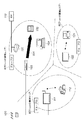
図1において、110は、ISP(Internet Service Provider)であり、101は、ISP110に接続され、ルータ機能を備えた無線LANのアクセスポイント装置である。
In FIG. 1, 110 is an ISP (Internet Service Provider), and 101 is a wireless LAN access point device connected to the
100は、アクセスポイント装置101の制御エリアを示している。該制御エリアにおいて各通信装置(102〜104、111、112、121、122)は、チャネル7によりメッセージ通信可能にアクセスポイント装置101にアソシエートしている通信装置である。この結果、第1のネットワーク(ネットワーク(1)と称する)が形成されている。なお、当該ネットワーク(1)を形成するグループを、ここではグループ(1)と称することとする。
Reference numeral 100 denotes a control area of the
グループ(1)に属する各通信装置のうち、102は、通信装置に入出力デバイスを組み込んだPDA(Personal Digital Assistant)型のPDA装置である。 Of the communication apparatuses belonging to the group (1), 102 is a PDA (Personal Digital Assistant) type PDA apparatus in which an input / output device is incorporated in the communication apparatus.
103はチューナ装置であり、104は管理装置である。管理装置104は、アクセスポイント装置101にアソシエート中の複数の通信装置の通信リソースを管理するとともに、ネットワークの分離、消滅及び再構築に応じて各ネットワークを形成する各グループを管理する。
111は、アクセスポイント機能を備える大型のディスプレイ装置であり、112は、デジタルビデオカメラ(DVC)である。120は、放送用受信アンテナであり、受信した放送用信号をチューナ装置103とディスプレイ装置111にそれぞれ分波器を介して送信する。
121は、ゲーム機能を搭載した端末装置であり、122は、アクセスポイント機能を備える小型のディスプレイ装置である。
<2.ネットワーク分離時に送受信されるメッセージの流れ>
図2は、本実施形態にかかる管理装置104の第1の受信手段及び第1の送信手段が、ネットワーク(1)の分離に際して、ネットワーク(1)から離脱する通信装置との間で送受信するメッセージの流れを示した図である。
<2. Flow of messages sent and received during network separation>
FIG. 2 shows messages that the first receiving unit and the first transmitting unit of the
図2では、ディスプレイ装置111、DVC112、端末装置121、ディスプレイ装置122が、ネットワーク(1)からの離脱を要求する場合について示している。
FIG. 2 shows a case where the
図中の矢印201、202は、アクセスポイント装置101を介して各通信装置と管理装置104とが送受信するメッセージの流れを示している。なお、図2の例では、ディスプレイ装置111及びDVC112と、端末装置121及びディスプレイ装置122は、ネットワーク(1)から離脱し、それぞれ異なるネットワークを形成する。
なお、ネットワーク(1)から離脱したディスプレイ装置111及びDVC112が属するグループを、グループ(2)と称し、端末装置121及びディスプレイ装置122が属するグループを、グループ(3)と称することとする。
A group to which the
<3.メッセージの構成>
次に、図2に示したメッセージ201、202を含む各種メッセージ(通信システムにおいて送受信されるメッセージ)の詳細な構成について図3を用いて説明する。
<3. Message structure>
Next, a detailed configuration of various messages (messages transmitted and received in the communication system) including the
図3は、通信システムにおいて送受信されるメッセージのMACフレーム構成を示した図である。 FIG. 3 is a diagram showing a MAC frame configuration of messages transmitted and received in the communication system.
図3の(b)はMACフレームの全体構成を示した図であり、図3の(a)はそのうちのFrame Controlフィールドの構成を示した図である。 FIG. 3B is a diagram showing the overall configuration of the MAC frame, and FIG. 3A is a diagram showing the configuration of the Frame Control field.
E301は、MACフレームのタイプを示す情報要素である。ここでは、管理フレームであることを示す“00”が格納されている。 E301 is an information element indicating the type of the MAC frame. Here, “00” indicating a management frame is stored.
E302は、MACフレームのサブタイプを示す情報要素である。ここでは、ACTIONであることを示す“1101”が格納されている。 E302 is an information element indicating a subtype of the MAC frame. In this case, “1101” indicating the ACTION is stored.
図3の(c)、(d)、(e)はMACフレームのFrame Bodyフィールドの構成を示した図であり、それぞれグループ変更要求、グループ変更応答、グループ消滅通知の各メッセージにおける情報要素を示している。 (C), (d), and (e) of FIG. 3 are diagrams showing the structure of the Frame Body field of the MAC frame, and show information elements in each message of a group change request, a group change response, and a group disappearance notification. ing.
なお、ネットワーク(1)からの離脱の要求に際しては、グループ変更要求メッセージと、グループ変更応答メッセージが用いられる。 It should be noted that a group change request message and a group change response message are used when requesting to leave the network (1).
E303、E310、E317は、メッセージのカテゴリを示す情報要素である。この情報要素が“4”の場合、当該メッセージは、ネットワークの分離、消滅及び再構築に関するメッセージであることを示している。 E303, E310, and E317 are information elements indicating message categories. When this information element is “4”, this message indicates that the message is related to the separation, disappearance, and reconstruction of the network.
E304、E311、E318は、メッセージの種別を示す情報要素である。この情報要素が“0”、“1”、“2”の場合、それぞれグループ変更要求、グループ変更応答、グループ消滅通知であることを示す。 E304, E311, and E318 are information elements indicating message types. When this information element is “0”, “1”, “2”, it indicates a group change request, a group change response, and a group disappearance notification, respectively.
E305、E313、E319はメッセージの送信先の通信装置のMACアドレスを示す情報要素であり、E306、E314,E320は送信元の通信装置のMACアドレスを示す情報要素である。 E305, E313, and E319 are information elements indicating the MAC address of the communication device that is the message transmission destination, and E306, E314, and E320 are information elements indicating the MAC address of the communication device that is the transmission source.
E307、E315は、グループ変更情報を示す情報要素である。グループ変更情報の詳細は図4に示す通りであり、ネットワークの分離のための情報と、ネットワークの再構築のための情報とを含む。具体的には、グループ変更情報には、「相対MACアドレス」、「ESSID」と、「起動モード」、「次のアソシエートネットワークについての情報」が含まれる。 E307 and E315 are information elements indicating group change information. The details of the group change information are as shown in FIG. 4 and include information for network separation and information for network reconstruction. Specifically, the group change information includes “relative MAC address”, “ESSID”, “activation mode”, and “information about the next associated network”.
このうち、「ESSID」、「起動モード」、「次のアソシエートネットワークについての情報」は、管理装置104に予め格納されており、管理装置104により、設定される。
Among these, “ESSID”, “startup mode”, and “information about the next associated network” are stored in advance in the
「ESSID」には、離脱した通信装置が属するグループにより新たに形成されるネットワークの識別子が格納される。また、「起動モード」には、新たにネットワークを形成する時に、APモードとSTAモードのどちらで動作するかについての情報が格納される。また「次のアソシエートネットワークについての情報」には、消滅したネットワークを形成していた通信装置が次のアソシエートネットワークを検知するために用いるネットワーク識別子(ESSID)が格納されている。 In “ESSID”, an identifier of a network newly formed by the group to which the disconnected communication device belongs is stored. The “startup mode” stores information about whether to operate in the AP mode or the STA mode when a new network is formed. The “information about the next associate network” stores a network identifier (ESSID) that is used by the communication device that formed the extinct network to detect the next associate network.
図3に戻る。E308、E316は、ネットワークの分離、消滅及び再構築に伴うグループ変更で用いるチャネル情報を示す情報要素である。E309は、グループ変更応答メッセージの待ち時間の設定に用いられるタイムアウト値を示す情報要素である。 Returning to FIG. E308 and E316 are information elements indicating channel information used for group change accompanying network separation, disappearance, and reconfiguration. E309 is an information element indicating a timeout value used for setting the waiting time of the group change response message.
例えば、E309が“0”に設定されたグループ変更要求メッセージを送信した通信装置は、グループ変更応答メッセージの受信を待たない。そして、当該グループ変更要求メッセージを送信した通信装置は、グループ変更情報E307とチャネル情報E308とを参照して、新たなネットワーク(第2のネットワーク)を形成する。 For example, a communication apparatus that has transmitted a group change request message in which E309 is set to “0” does not wait for reception of a group change response message. And the communication apparatus which transmitted the said group change request message forms a new network (2nd network) with reference to the group change information E307 and the channel information E308.
E312は、グループ変更応答メッセージのステータスコードを示す情報要素であり、グループ変更が可能か否かを示す情報が格納される。 E312 is an information element indicating the status code of the group change response message, and stores information indicating whether the group change is possible.
E321はグループ消滅理由を示す情報要素であり、ネットワークが再構築され、直接通信が正常に終了したことを示す情報が格納される。 E321 is an information element indicating the reason for group disappearance, and stores information indicating that the network has been reconstructed and direct communication has been completed normally.
<4.ネットワーク分離時の通信システム全体の処理の流れ>
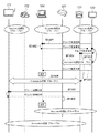
図5は、ネットワーク分離時の通信システム全体の処理の流れを示すシーケンス図である。
<4. Processing flow of the entire communication system during network separation>
FIG. 5 is a sequence diagram showing a processing flow of the entire communication system at the time of network separation.
はじめに、通信システムは、管理装置104およびディスプレイ装置111、DVC112、端末装置121、ディスプレイ装置122が、アクセスポイント装置101にアソシエートした状態(M501)にあるものとする。
First, it is assumed that the communication system is in a state (M501) in which the
かかる状態において、ユーザの操作により、ディスプレイ装置111の表示画面から、DVC112を指定したうえでネットワーク(1)からの離脱が要求されると、ネットワークの分離に関するメッセージ201の送受信が開始される。
In this state, when the user designates the
ディスプレイ装置111は、ネットワーク(1)から離脱し、DVC112との間で新たなネットワークを形成するために、グループ変更要求メッセージ(M502)を管理装置104に対して送信する。
The
この時、グループ変更要求メッセージ(M502)のE305には、管理装置104のMACアドレスが、また、E307の相対MACアドレスには、新たなネットワークを形成するDVC112のMACアドレスがそれぞれ設定される。
At this time, the MAC address of the
管理装置104は、受信したグループ変更要求メッセージ(M502)のE307を解析し、相対先(DVC112)を確認する。
The
次に、管理装置104は、DVC112に送信するグループ変更要求メッセージのグループ変更情報E307に、ESSIDと、起動モード、次のアソシエートネットワークについての情報を設定する。
Next, the
ここでは、ESSID、起動モード、次のアソシエートネットワークについての情報を、それぞれ“GP2/STA/GP1”と設定するものとする。 Here, it is assumed that the information about the ESSID, the startup mode, and the next associate network is set as “GP2 / STA / GP1”, respectively.
“GP2”は、新たに形成するネットワークのESSIDが、GP2であることを示し、“STA”は、DVC112に対して、STAモードで起動するよう要求していることを示す。
“GP2” indicates that the ESSID of the newly formed network is GP2, and “STA” indicates that the
また、“GP1”は、ネットワーク消滅後は、GP1のESSIDを有するネットワークに再接続するよう要求していることを示す。 “GP1” indicates that after the network disappears, it is requested to reconnect to the network having the ESSID of GP1.
以上のようにグループ変更情報E307の設定が完了すると、管理装置104は、当該グループ変更情報E307を含むグループ変更要求メッセージ(M503)をDVC112に送信する。
When the setting of the group change information E307 is completed as described above, the
このとき、グループ変更要求メッセージ(M503)の送信先MACアドレスE305には、DVC112のMACアドレスが設定される。
At this time, the MAC address of the
また、グループ変更情報E307にある相対MACアドレスには、新たなネットワークを形成するディスプレイ装置111のMACアドレスが設定される。
Further, the MAC address of the
DVC112は、グループ変更要求メッセージ(M503)を受信すると、メッセージ内のグループ変更情報E307を解析し、相対先(ディスプレイ装置111)を確認する。
When receiving the group change request message (M503), the
次に、DVC112は、ディスプレイ装置111との間で新たなネットワークを形成することが可能であるか否かを判断する。
Next, the
新たなネットワークを形成することが可能であると判断した場合には、メッセージ内のグループ変更情報E307をDVC112内の記憶領域に格納し、管理装置104に対してグループ変更応答メッセージ(M504)を返信する。
If it is determined that a new network can be formed, the group change information E307 in the message is stored in the storage area in the
この時、グループ変更応答メッセージ(M504)中のステータスコードE312には、グループ変更が可能であることを示す情報を設定する。また、受信したグループ変更要求メッセージ(M503)のグループ変更情報E307の相対MACアドレスを、そのままグループ変更応答メッセージのグループ変更情報E315にコピーする。 At this time, information indicating that the group can be changed is set in the status code E312 in the group change response message (M504). Further, the relative MAC address of the group change information E307 in the received group change request message (M503) is directly copied to the group change information E315 in the group change response message.
以上のようにグループ変更応答メッセージの設定が完了すると、DVC112は、グループ変更応答メッセージ(M505)を管理装置104に送信する。
When setting of the group change response message is completed as described above, the
次に、DVC112は、記憶領域に格納したグループ変更情報E307及びチャネル情報E308を参照し、STAモードで起動する。
Next, the
グループ変更応答メッセージ(M505)を受信した管理装置104は、グループ変更情報E315を解析し、相対先(ディスプレイ装置111)を確認する。
The
次に、管理装置104は、ディスプレイ装置111に送信するグループ変更応答メッセージのグループ変更情報E315に、ESSID、起動モード、次のアソシエートネットワークについての情報を設定する。
Next, the
ここでは、ESSID、起動モード、次のアソシエートネットワークについての情報を、それぞれ“GP2/AP/GP1”と設定するものとする。 Here, it is assumed that the information about the ESSID, the startup mode, and the next associate network is set as “GP2 / AP / GP1”, respectively.
“GP2”は、新たに形成するネットワークのESSIDが、GP2であることを示し、“AP”は、ディスプレイ装置111に対して、APモードで起動するよう要求していることを示す。
“GP2” indicates that the ESSID of the newly formed network is GP2, and “AP” indicates that the
また、“GP1”は、ネットワーク消滅後は、GP1のESSIDを有するネットワークにSTAモードで再接続するよう要求していることを示す。 “GP1” indicates that, after the network disappears, it is requested to reconnect to the network having the ESSID of GP1 in the STA mode.
以上のようにグループ変更情報E315の設定が完了すると、管理装置104は、当該グループ変更情報E315を含むグループ変更応答メッセージ(M505)をディスプレイ装置111に送信する。
When the setting of the group change information E315 is completed as described above, the
グループ変更応答メッセージ(M505)を受信したディスプレイ装置111は、メッセージ内のグループ変更情報E315をディスプレイ装置111内の記憶領域に格納する。
The
次に、ディスプレイ装置111は、記憶領域に格納したグループ変更情報E315及びチャネル情報E316を参照し、APモードで起動する。
Next, the
APモードで起動したディスプレイ装置111は、STAモードで起動中のDVC112との間でアソシエーションと認証(M506)を行う。
The
以降、ディスプレイ装置111とDVC112は、新たなネットワーク(ネットワーク(2)と称する)を形成する。
Thereafter, the
続いて、端末装置121に対するユーザの操作により、ネットワーク(1)から離脱して、新たなネットワークを形成する場合の処理について説明する。
Next, processing in the case of leaving the network (1) and forming a new network by a user operation on the
端末装置121の表示画面から、ディスプレイ装置122を指定したうえでネットワーク(1)からの離脱を要求すると、ネットワークの分離に関するメッセージ202の送受信が開始される。
When the
端末装置121は、ネットワーク(1)から離脱し、ディスプレイ装置122との間で新たなネットワークを形成するために、グループ変更要求メッセージ(M507)を管理装置104に対して送信する。
The
この時、グループ変更要求メッセージ(M507)の送信先MACアドレスE305には、管理装置104のMACアドレスが設定される。また、グループ変更情報E307の相対MACアドレスには、新たなネットワークを形成するディスプレイ装置122のMACアドレスが設定される。
At this time, the MAC address of the
管理装置104は、受信したグループ変更要求メッセージ(M507)のグループ変更情報E307を解析し、相対先(ディスプレイ装置122)を確認する。
The
次に、管理装置104は、ディスプレイ装置122に送信するグループ変更要求メッセージのグループ変更情報E307に、ESSID、起動モード、次のアソシエートネットワークについての情報を設定する。
Next, the
ここでは、ESSID、起動モード、次のアソシエートネットワークについての情報を、それぞれ、“GP3/AP/GP1、GP2”と設定するものとする。 Here, it is assumed that the information about the ESSID, the startup mode, and the next associate network is set as “GP3 / AP / GP1, GP2”, respectively.
“GP3”は、新たに形成するネットワークのESSIDが、GP3であることを示している。また、“AP”は、ディスプレイ装置122に対して、APモードで起動するよう要求していることを示す。
“GP3” indicates that the ESSID of the newly formed network is GP3. “AP” indicates that the
また、“GP1、GP2”は、ネットワーク消滅後は、GP1またはGP2のESSIDを有するネットワークに再接続するよう要求していることを示す。 “GP1, GP2” indicates that after the network disappears, a request is made to reconnect to a network having the ESSID of GP1 or GP2.
以上のようにグループ変更情報E307の設定が完了すると、管理装置104は、当該グループ変更情報E307を含むグループ変更要求メッセージ(M508)をディスプレイ装置122に送信する。
When the setting of the group change information E307 is completed as described above, the
このとき、グループ変更要求メッセージ(M508)の送信先MACアドレスE305には、ディスプレイ装置122のMACアドレスが設定される。
At this time, the MAC address of the
また、グループ変更情報E307にある相対MACアドレスには、新たなネットワークを形成する端末装置121のMACアドレスが設定される。
Further, the MAC address of the
ディスプレイ装置122は、グループ変更要求メッセージ(M508)を受信すると、メッセージ内のグループ変更情報E307を解析し、相対先(端末装置121)を確認する。
Upon receiving the group change request message (M508), the
次に、ディスプレイ装置122は、端末装置121との間で新たなネットワークを形成することが可能であるか否かを判断する。
Next, the
新たなネットワークを形成することが可能であると判断した場合には、メッセージ内のグループ変更情報E307及びチャネル情報E308をディスプレイ装置122内の記憶領域に格納する。また、管理装置104に対してグループ変更応答メッセージ(M509)を返信する。
When it is determined that a new network can be formed, the group change information E307 and the channel information E308 in the message are stored in the storage area in the
この時、グループ変更応答メッセージ(M509)中のステータスコードE312には、グループ変更が可能であることを示す情報を設定する。また、受信したグループ変更要求メッセージ(M508)のグループ変更情報E307の相対MACアドレスを、そのままグループ変更応答メッセージのグループ変更情報E315にコピーする。 At this time, information indicating that the group can be changed is set in the status code E312 in the group change response message (M509). Further, the relative MAC address of the group change information E307 in the received group change request message (M508) is directly copied to the group change information E315 in the group change response message.
以上のようにグループ変更応答メッセージの設定が完了すると、ディスプレイ装置122は、グループ変更応答メッセージ(M509)を管理装置104に送信する。
When the setting of the group change response message is completed as described above, the
次に、ディスプレイ装置122は、記憶領域に格納したグループ変更情報E307及びチャネル情報E308を参照し、APモードで起動する。
Next, the
グループ変更応答メッセージ(M509)を受信した管理装置104は、グループ変更情報E315を解析し、相対先(端末装置121)を確認する。
The
次に、管理装置104は、端末装置121に送信するグループ変更応答メッセージのグループ変更情報E315に、ESSID、起動モード、次のアソシエートネットワークについての情報を設定する。
Next, the
ここでは、ESSID、起動モード、次のアソシエートネットワークについての情報を、それぞれ、“GP3/STA/GP1、GP2”と設定するものとする。 Here, it is assumed that the information about the ESSID, the startup mode, and the next associate network is set as “GP3 / STA / GP1, GP2”, respectively.
“GP3”は、新たに形成するネットワークのESSIDが、GP3であることを示し、“STA”は、端末装置121に対して、STAモードで起動するよう要求していることを示す。
“GP3” indicates that the ESSID of the newly formed network is GP3, and “STA” indicates that the
また、“GP1、GP2”は、ネットワーク消滅後は、GP1またはGP2のESSIDを有するネットワークに再接続するよう要求していることを示す。 “GP1, GP2” indicates that after the network disappears, a request is made to reconnect to a network having the ESSID of GP1 or GP2.
以上のようにグループ変更情報E315の設定が完了すると、管理装置104は、当該グループ変更情報E315を含むグループ変更応答メッセージ(M510)を端末装置121に送信する。
When the setting of the group change information E315 is completed as described above, the
グループ変更応答メッセージ(M510)を受信した端末装置121は、メッセージ内のグループ変更情報E315を端末装置121内の記憶領域に格納する。
The
次に、端末装置121は、記憶領域に格納したグループ変更情報E315及びチャネル情報E316を参照し、STAモードで起動する。
Next, the
STAモードで起動した端末装置121は、APモードで起動中のディスプレイ装置122との間でアソシエーションと認証(M511)を行う。
The
以降、端末装置121とディスプレイ装置122は、新たなネットワーク(ネットワーク(3)と称す)を形成する。
Thereafter, the
以上の処理により、図1に示すネットワーク(1)は分離され、図6に示すネットワーク構成となる。図6は、図5に示す処理の結果、ネットワーク(1)が、ネットワーク(1)〜(3)に分離された様子を示している。 Through the above processing, the network (1) shown in FIG. 1 is separated and the network configuration shown in FIG. 6 is obtained. FIG. 6 shows a state where the network (1) is separated into the networks (1) to (3) as a result of the processing shown in FIG.
図6に示すように、ネットワーク(1)〜(3)を形成する各AP機能を有する通信装置(101、111、122)は、それぞれ、600〜602に示す制御エリアを有する。 As shown in FIG. 6, the communication devices (101, 111, 122) having the AP functions forming the networks (1) to (3) have control areas indicated by 600 to 602, respectively.
それぞれの制御エリアでは、異なるチャネルを使用して異なるBSS(Basic Service Set)が構築され、インフラストラクチャ・モードで運用される。 In each control area, different basic service sets (BSSs) are constructed using different channels and are operated in the infrastructure mode.
図6に示すように、ネットワーク(1)を形成するグループ(グループ(1))には、アクセスポイント装置101、PDA装置102、チューナ装置103、管理装置104が属することとなる。
As shown in FIG. 6, the
また、ネットワーク(2)を形成するグループ(グループ(2))には、ディスプレイ装置111、DVC112が属することとなる。更に、ネットワーク(3)を形成するグループ(グループ(3))には、ディスプレイ装置122、端末装置121が属することとなる。
Further, the
<5.ネットワーク分離後の各通信装置の処理(ネットワークの消滅、再構築)の流れ>
次に、ネットワークが分離された後の各通信装置の処理について説明する。上述したように、通信システムを構成する各通信装置は、新たに形成されたネットワークにおいて所望の無線通信が完了すると、該ネットワークを消滅させ、ネットワークを再構築できるよう構成されている。
<5. Flow of processing (deletion and reconstruction of network) of each communication device after network separation>
Next, processing of each communication device after the network is separated will be described. As described above, each communication device constituting the communication system is configured such that, when desired wireless communication is completed in a newly formed network, the network is extinguished and the network can be reconstructed.
図7は、ネットワーク分離後の各通信装置の処理(ネットワークの消滅、再構築)の流れを示す図である。以下、各通信装置の処理について、図7を参照しながら、次のアソシエートネットワークが検知される場合と、検知されない場合とに分けて説明する。 FIG. 7 is a diagram illustrating a flow of processing (network disappearance, reconfiguration) of each communication device after network separation. Hereinafter, the processing of each communication apparatus will be described separately with reference to FIG. 7 when the next associated network is detected and when it is not detected.
5.1 次のアソシエートネットワークが検知される場合の処理
図6において端末装置121とディスプレイ装置122とが属するグループ(3)が形成するネットワーク(3)の消滅条件は以下のとおりである。
(A)端末装置121がネットワーク(3)から離脱または離脱要求
(B)ディスプレイ装置122がAP機能を停止または停止要求
ディスプレイ装置122が上記消滅条件(A)を検出した場合(ステップS701のYES)、記憶領域に格納したグループ変更情報E307を解析する(ステップS702)。
5.1 Processing when Next Associate Network is Detected The extinction conditions for the network (3) formed by the group (3) to which the
(A)
ディスプレイ装置122の記憶領域にそれぞれ格納された「次のアソシエートネットワークについての情報」は、“GP1”または“GP2”である。
“Information about the next associate network” stored in the storage area of the
はじめに、それぞれの装置がGP1のESSIDを有するネットワーク(ネットワーク(1))に再接続する場合(グループ(1)のアクセスポイント装置101にアソシエートする場合)の処理について説明する。
First, processing when each device reconnects to the network (network (1)) having the ESSID of GP1 (when associating with the
次のアソシエートネットワークについての情報が存在すると判断すると(ステップS703のYES)、ネットワーク(ここでは、ネットワーク(1))をスキャンする(ステップS704)。更に、スキャン処理のタイマーをセットする(ステップS705)。 If it is determined that there is information about the next associate network (YES in step S703), the network (here, network (1)) is scanned (step S704). Further, a timer for scan processing is set (step S705).
タイマー処理の満了以前(ステップS706のNO)に、ネットワーク(ネットワーク(1))が検知された場合(ステップS707のYES)には、ステップS708に進む。ステップS708では、該ネットワークを形成するグループに属する通信装置(ここでは、アクセスポイント装置101)に対して、アソシエート処理を実行する。 If the network (network (1)) is detected (YES in step S707) before the timer process expires (NO in step S706), the process proceeds to step S708. In step S708, an association process is executed for the communication devices (in this case, the access point device 101) belonging to the group forming the network.
ディスプレイ装置122は、アソシエートが完了すると(ステップS709のYES)、グループ(1)に属することとなり、ネットワーク(1)が再構築されることとなる。
When the association is completed (YES in step S709), the
なお、端末装置121が上記消滅条件(B)を検出した場合においても、ステップS701〜S709の処理は同様に実施される。その結果、端末装置121及びディスプレイ装置122はグループ(1)に属することとなり、ネットワーク(1)が再構築されることとなる。
Even when the
図8は、図7に示す処理の結果、ネットワーク(3)が消滅し、ネットワーク(1)が再構築された様子を示す図である。 FIG. 8 is a diagram illustrating a state in which the network (3) disappears and the network (1) is reconstructed as a result of the processing illustrated in FIG.
5.2 次のアソシエートネットワークが検知されない場合の処理
次にディスプレイ装置122と端末装置121が、次のアソシエートネットワークを検知することができない場合の処理について説明する。なお、次のアソシエートネットワークを検知することができない場合とは、例えば、図9に示すような状態が挙げられる。
5.2 Processing when Next Association Network is not Detected Next, processing when the
図9は、ネットワーク(1)が、ネットワーク(1)〜(3)に分離された状態において、各ネットワークにおいて無線通信が行われている様子を示す図である。 FIG. 9 is a diagram illustrating a state in which wireless communication is performed in each network in a state where the network (1) is separated into the networks (1) to (3).
ここで、制御エリア600では、チューナ装置103からPDA装置102に伝送される動画データ901によって、ネットワーク(1)内で使用可能な帯域の大半が使用されているものとする。
Here, in the control area 600, it is assumed that most of the bandwidth that can be used in the network (1) is used by the moving
このとき、管理装置104では、無線通信の通信リソース管理の観点から、アクセスポイント装置101に対して、ステルスモードに移行するよう指示する。
At this time, the
ステルスモードとは、制御エリア600のESSIDを隠蔽することにより、任意の通信装置から容易にアクセスされることを回避するためのモードである。この場合、ディスプレイ装置122及び端末装置121は、次のアソシエートネットワークとしてネットワーク(1)を検知することができなくなる。以下では、このような状態のもとでの各通信装置の処理について、図7に従って説明する。
The stealth mode is a mode for avoiding easy access from an arbitrary communication device by concealing the ESSID of the control area 600. In this case, the
ディスプレイ装置122が、端末装置121のネットワーク(3)からの離脱を検出すると(ステップS701のYES)、ディスプレイ装置122は、格納したグループ変更情報E307を解析する(ステップS702)。
When the
端末装置121とディスプレイ装置122の記憶領域にそれぞれ格納された「次のアソシエートネットワークについての情報」は、“GP1”と“GP2”である。
“Information about the next associated network” stored in the storage areas of the
ディスプレイ装置122は、次のアソシエートネットワークについての情報が存在すると判断すると(ステップS703のYES)、ネットワーク(ここでは、ネットワーク(1))をスキャンする(ステップS704)。次に、スキャン処理のタイマーをセットする(ステップS705)。
When the
タイマー処理の満了(ステップS706のYES)までに、ネットワーク(ネットワーク(1))が検知されない場合(ステップS707のNO)には、再度グループ変更情報E307を解析する(ステップS702)。 If the network (network (1)) is not detected (NO in step S707) by the expiration of the timer process (YES in step S706), the group change information E307 is analyzed again (step S702).
上述のように、アクセスポイント装置101は、ステルスモードに移行中であるため、ネットワーク(1)は検知されず、再度グループ変更情報E307を解析することとなる。
As described above, since the
グループ変更情報E307を解析した結果、次のアソシエートネットワークについての情報が存在すると判断すると(ステップS703のYES)、そのネットワーク(ここでは、ネットワーク(2))をスキャンする(ステップS704)。更に、スキャン処理のタイマーをセットする(ステップS705)。 As a result of analyzing the group change information E307, if it is determined that information about the next associate network exists (YES in step S703), the network (here, network (2)) is scanned (step S704). Further, a timer for scan processing is set (step S705).
タイマー処理の満了以前(ステップS706のNO)に、ネットワーク(ネットワーク(2))が検知された場合(ステップS707のYES)には、ステップS708に進む。ステップS708では、該ネットワークを形成するグループに属する通信装置(ここでは、ディスプレイ装置111)に対してアソシエート処理を実行する。 If the network (network (2)) is detected (YES in step S707) before the timer process expires (NO in step S706), the process proceeds to step S708. In step S708, an association process is executed for the communication devices (here, the display device 111) belonging to the group forming the network.
ディスプレイ装置122は、アソシエートが完了すると(ステップS709のYES)、グループ(2)に属することとなり、ネットワーク(2)が再構築されることとなる。
When the association is completed (YES in step S709), the
図10は、図7に示す処理の結果、ネットワーク(3)が消滅し、ネットワーク(2)が再構築された様子を示す図である。 FIG. 10 is a diagram illustrating a state in which the network (3) disappears and the network (2) is reconstructed as a result of the processing illustrated in FIG.
なお、次のアソシエートネットワークについての情報として記憶されたESSIDを有するネットワークをいずれも検知出来ない場合(ステップS703のNO)には、ディスプレイ装置122は、再度APモードで起動する。そして、端末装置121は、再度STAモードで起動する。この結果、ネットワーク(3)が形成されることとなる(ステップS710)。
When none of the networks having the ESSID stored as information about the next associate network can be detected (NO in step S703), the
なお、端末装置121が上記消滅条件(B)を検出した場合においても、ステップS701〜S709の処理は、同様に実施される。その結果、端末装置121及びディスプレイ装置122は、グループ(2)に属することとなり、ネットワーク(2)が再構築されることとなる。
Even when the
<6.グループ管理テーブル>
図11は、管理装置104の記憶領域に格納されたグループ管理テーブルの詳細を示す図であり、ネットワーク(1)が分離された後のグループ管理テーブルを示している。
<6. Group management table>
FIG. 11 is a diagram showing details of the group management table stored in the storage area of the
以上の説明から明らかなように、本実施形態では、通信システムに管理装置104を配し、ネットワークが分離される際に、該管理装置104が、通信装置に対して、分離のための通信リソースと再構築のための通信リソースを指示する構成とした。これにより、ネットワークから離脱し、新たなネットワークを形成する通信装置は、当該通信リソース情報に基づいてネットワークを形成することとなり、管理装置が、ネットワークの通信リソースを管理することが可能となる。
As is apparent from the above description, in this embodiment, when the
また、新たに形成されたネットワークが消滅し、再構築された場合においても、再構築された後の通信リソースを管理することが可能となる。 Further, even when a newly formed network disappears and is reconfigured, it becomes possible to manage communication resources after the reconfiguration.
[第2の実施形態]
上記第1の実施形態では、ネットワークが分離される際に、分離のための通信リソースと再構築のための通信リソースを、通信装置に設定することで、各通信装置の通信リソースを管理する構成とした。しかしながら、本発明はこれに限定されず、ネットワークが分離される際に分離のための通信リソースを指示し、ネットワークが消滅した際に、再構築のための通信リソースを指示するようにしてもよい。
[Second Embodiment]
In the first embodiment, when the network is separated, the communication resource for separation and the communication resource for reconstruction are set in the communication device, thereby managing the communication resource of each communication device. It was. However, the present invention is not limited to this, and communication resources for separation may be instructed when the network is separated, and communication resources for reconstruction may be instructed when the network disappears. .
また、上記第1の実施形態では、ネットワークが分離した後のグループについて管理する構成について説明したが、本発明はこれに限定されない。例えば、分離したネットワークが消滅し、再構築された後のグループについても管理するように構成してもよい。 Moreover, although the said 1st Embodiment demonstrated the structure which manages about the group after a network isolate | separates, this invention is not limited to this. For example, the group after the separated network disappears and is reconfigured may be managed.
以下、本実施形態の詳細について説明する。なお、ネットワークを分離するまでの処理は、上記第1の実施形態と同様であるため説明は省略し、以下では、ネットワークの消滅、再構築における処理について説明する。 Details of this embodiment will be described below. Note that the processing until the network is separated is the same as that in the first embodiment, and thus the description thereof is omitted. Hereinafter, processing in the disappearance and reconstruction of the network will be described.
<1.ネットワークの消滅、再構築時に送受信されるメッセージの流れ>
図12は、本実施形態にかかる管理装置104の第2の受信手段及び第2の送信手段が、WDS機能を利用して、ネットワーク(3)の消滅を通知するディスプレイ装置122との間で送受信するメッセージの流れを示した図である。
<1. Flow of messages sent and received when the network disappears or is rebuilt>
In FIG. 12, the second receiving unit and the second transmitting unit of the
管理装置104とディスプレイ装置122とは、WDS(Wireless Distribution System)を用いてメッセージ1201の送受信を行う。
The
図13は、本実施形態にかかる管理装置104の第2受信手段及び第2の送信手段が、WDS機能を利用して、ネットワーク(1)、(2)が再構築された後に、ディスプレイ装置111との間で送受信するメッセージの流れを示した図である。
FIG. 13 illustrates the
管理装置104とディスプレイ装置111とは、WDSを用いてメッセージ1302の送受信を行う。
The
<2.ネットワークの消滅、再構築時の通信システム全体の処理の流れ>
図14は、端末装置121とディスプレイ装置122とにより形成されるネットワーク(3)が消滅し、ネットワーク(1)、(2)が再構築される場合の通信システム全体の処理の流れを示すシーケンス図である。
<2. Processing flow of the entire communication system when the network disappears or is rebuilt>
FIG. 14 is a sequence diagram showing a processing flow of the entire communication system when the network (3) formed by the
また、図15は、その場合の端末装置121とディスプレイ装置122における処理の流れを示すフローチャートである。
FIG. 15 is a flowchart showing the flow of processing in the
以下、図14及び図15を用いて、ネットワーク(3)の消滅及びネットワーク(1)、(2)の再構築時の通信システム全体の処理の流れについて説明する。 Hereinafter, the flow of processing of the entire communication system when the network (3) disappears and the networks (1) and (2) are reconstructed will be described with reference to FIGS.
端末装置121とディスプレイ装置122とで形成されるネットワーク(3)の消滅条件は第1の実施形態と同様に以下のとおりである。
(A)端末装置121がネットワーク(3)から離脱または離脱要求
(B)ディスプレイ装置122がAP機能を停止または停止要求
ディスプレイ装置122は、上記消滅条件(A)を検出した場合(ステップS1501のYES)、WDSで管理装置104にグループ消滅通知メッセージ(M1401)を送信する(ステップS1502)。
The extinction conditions for the network (3) formed by the
(A) The
この時、送信先MACアドレスE319には、管理装置104のMACアドレスが、また、送信元MACアドレスE320には、ディスプレイ装置122のMACアドレスがそれぞれ設定される。
At this time, the MAC address of the
グループ消滅通知メッセージ(M1401)を受信した管理装置104では、該メッセージ(M1401)のグループ消滅理由E321を調べ、正常終了であることを確認する。
The
次に、該メッセージ(M1401)の送信元MACアドレスE320を解析し、送信元がディスプレイ装置122であることを確認する。
Next, the source MAC address E320 of the message (M1401) is analyzed to confirm that the source is the
同時に、管理装置104は、グループ管理テーブル(図11)を参照し、ディスプレイ装置122にアソシエートしていた端末装置121の存在を認識する。
At the same time, the
次に、管理装置104は、ディスプレイ装置122に送信するグループ要求変更メッセージのグループ変更情報E307に、起動モード、次のアソシエートネットワークについての情報を設定する。
Next, the
ここでは、起動モード及び次のアソシエートネットワークについての情報を、それぞれ“STA/GP1”、“STA/GP2”と設定するものとする。 Here, it is assumed that the information about the activation mode and the next associate network is set as “STA / GP1” and “STA / GP2”, respectively.
起動モード=“STA”は、ディスプレイ装置122と、端末装置121のそれぞれに対して、STAモードで起動するよう要求していることを示す。
The activation mode = “STA” indicates that each of the
次のアソシエートネットワークについての情報=“GP1”は、ネットワーク消滅後は、GP1のESSIDを有するネットワーク(ネットワーク(1))に再接続するよう要求していることを示す。 The information about the next associate network = “GP1” indicates that after the network disappears, it is requested to reconnect to the network (network (1)) having the ESSID of GP1.
同様に、次のアソシエートネットワークについての情報=“GP2”は、ネットワーク消滅後は、GP2のESSIDを有するネットワーク(ネットワーク(2)に再接続するよう要求していることを示す。 Similarly, the information about the next associate network = “GP2” indicates that after the network disappears, it is requested to reconnect to the network (network (2)) having the ESSID of GP2.
以上のようにグループ変更情報E307の設定が完了すると、管理装置104は、グループ変更情報を含むグループ変更要求メッセージ(M1402)をディスプレイ装置122に送信する(ステップS1502)。
When the setting of the group change information E307 is completed as described above, the
このとき、グループ変更要求メッセージ(M1402)の送信先MACアドレスE305には、ディスプレイ装置122のMACアドレスが設定される。
At this time, the MAC address of the
ディスプレイ装置122は、グループ変更要求メッセージ(M1402)を受信すると(ステップS1503のYES)、グループ変更情報E307を解析する(ステップS1504)。
When receiving the group change request message (M1402) (YES in step S1503), the
解析の結果、次のアソシエートネットワークについての情報として、“GP2”が設定されていることを確認する。 As a result of the analysis, it is confirmed that “GP2” is set as information about the next associate network.
ディスプレイ装置122は、現在の起動モードがAPモードであることから(ステップS1505のYES)、グループ変更要求メッセージ(M1403)を端末装置121に送信する。
The
このとき、グループ変更要求メッセージ(M1403)の起動モード及び次のアソシエートネットワークについての情報は、それぞれ“STA/GP2”と設定されるものとする(ステップS1514)。 At this time, it is assumed that the start mode of the group change request message (M1403) and the information about the next associate network are set to “STA / GP2”, respectively (step S1514).
以上の処理により、ディスプレイ装置122に対しては、管理装置104より、次のアソシエートネットワークについての情報として、“GP1”が指示される。
Through the above processing, “GP1” is instructed to the
また、端末装置121に対しては、管理装置104より、次のアソシエートネットワークについての情報として、“GP2”が指示される。
Further, “GP2” is instructed to the
ディスプレイ装置122は、ステップS1504における解析の結果、次のアソシエートネットワークについての情報が存在するか否かを確認する。
As a result of the analysis in step S1504, the
次のアソシエートネットワークについての情報が存在すると判断した場合(ステップS1506のYES)には、該ESSIDを有するネットワーク(ここでは、ネットワーク(1))をスキャンする(ステップS1507)。更に、スキャン処理のタイマーをセットする(ステップS1508)。 If it is determined that information about the next associate network exists (YES in step S1506), the network having the ESSID (here, network (1)) is scanned (step S1507). Further, a timer for scan processing is set (step S1508).
タイマー処理の満了以前(ステップS1509のNO)に、ネットワーク(ネットワーク(1))が検知された場合(ステップS1510のYES)には、アソシエート処理を実行する(ステップS1511)。 If the network (network (1)) is detected (YES in step S1510) before the timer process expires (NO in step S1509), the associate process is executed (step S1511).
ディスプレイ装置122は、ネットワーク(ネットワーク(1))を形成するアクセスポイント装置101とのアソシエート処理を完了すると(ステップS1512のYES)、グループ(1)に属することとなる。
When the
ディスプレイ装置122は、アソシエート処理と認証(M1404)を完了すると、管理装置104に対して、グループ変更応答メッセージ(M1405)を送信する(ステップS1513)。
When the
管理装置104は、グループ変更応答メッセージ(M1405)を受信すると、グループ変更要求メッセージ(M1402)に対する応答であることを認識し、グループ管理テーブルを更新する。
Upon receiving the group change response message (M1405), the
一方、次のアソシエートネットワークについての情報が示すESSIDを有するネットワークをいずれも検知することが出来ない場合(ステップS1506のNO)には、ディスプレイ装置122を再度APモードで起動する。これにより、ネットワーク(3)が形成されることとなる(ステップS1515)。
On the other hand, if none of the networks having the ESSID indicated by the information about the next associate network can be detected (NO in step S1506), the
同様に、端末装置121は、次のアソシエートネットワークについての情報が存在すると判断した場合(ステップS1506のYES)には、該ESSIDを有するネットワーク(ここでは、ネットワーク(2))をスキャンする(ステップS1507)。更に、スキャン処理のタイマーをセットする(ステップS1508)。
Similarly, when the
タイマー処理の満了以前(ステップS1509のNO)に、ネットワーク(ネットワーク(2))が検知された場合(ステップS1510のYES)には、アソシエート処理を実行する(ステップS1511)。 If the network (network (2)) is detected before the timer process expires (NO in step S1509) (YES in step S1510), the associate process is executed (step S1511).
端末装置121は、ネットワーク(ネットワーク(2))を形成するディスプレイ装置111とのアソシエートが完了すると(ステップS1512のYES)、グループ(2)に属することとなる。
When the
また、端末装置121は、アソシエートと認証(M1406)が完了すると、管理装置104に対して、グループ変更応答メッセージ(M1407)を送信する(ステップS1513)。
Further, when the association and authentication (M1406) is completed, the
この時、メッセージ(M1407)の送信先MACアドレスE314には、管理装置104のMACアドレスが、また、送信元MACアドレスE313には、端末装置121のMACアドレスがそれぞれ設定される。
At this time, the MAC address of the
グループ変更応答メッセージ(M1407)を受信したディスプレイ装置111は、WDSを用いて該メッセージ(M1408)をネットワーク(1)を形成するアクセスポイント装置101を介して管理装置104に送信する。
Upon receiving the group change response message (M1407), the
管理装置104は、該メッセージ(M1408)を受信すると、グループ変更要求メッセージ(M1407)に対する応答であることを認識し、グループ管理テーブルを更新する。
Upon receiving the message (M1408), the
一方、次のアソシエートネットワークについての情報が示すESSIDを有するネットワークをいずれも検知できない場合(ステップS1506のNO)には、端末装置121は再度STAモードで起動する。これにより、ネットワーク(3)が形成されることとなる(ステップS1515)。
On the other hand, when none of the networks having the ESSID indicated by the information about the next associate network can be detected (NO in step S1506), the
<4.グループ管理テーブル>
図16は、管理装置104の記憶領域に格納されたグループ管理テーブルの詳細を示す図である。図16は、ネットワーク(3)が消滅し、ネットワーク(1)、(2)が再構築された後のグループ管理テーブルを示している。
<4. Group management table>
FIG. 16 is a diagram showing details of the group management table stored in the storage area of the
以上の説明から明らかなように、本実施形態では、ネットワーク消滅時に、通信システム内に配された管理装置が、WDSを利用して通信装置と通信することにより、再構築のための通信リソースを指示する構成とした。 As is clear from the above description, in this embodiment, when the network disappears, the management device arranged in the communication system communicates with the communication device using WDS, so that communication resources for reconstruction are generated. It was set as the structure to instruct | indicate.
これにより、管理装置では、ネットワークが消滅し、他のネットワークが再構築された場合でも、各ネットワークの通信リソースを管理することが可能となる。 As a result, the management apparatus can manage the communication resources of each network even when the network disappears and another network is reconstructed.
また、本実施形態では、ネットワーク再構築時に、通信システム内に配された管理装置が、WDSを利用して通信装置と通信することにより、各ネットワークを形成するグループを管理する構成とした。 Further, in the present embodiment, when the network is reconfigured, the management apparatus arranged in the communication system manages the groups forming each network by communicating with the communication apparatus using WDS.
これにより、管理装置では、ネットワークが消滅し、他のネットワークが再構築された場合でも、各ネットワークを形成するグループを管理することが可能となる。 Thus, the management apparatus can manage the groups forming each network even when the network disappears and another network is reconstructed.
[第3の実施形態]
上記第1及び第2の実施形態では、次のアソシエートネットワークについての情報が示すESSIDを有するネットワークをいずれも検知出来ない場合には、端末装置が、以前のモードで起動することで、旧ネットワークの形成を継続することとした。
[Third Embodiment]
In the first and second embodiments, when none of the networks having the ESSID indicated by the information about the next associate network can be detected, the terminal device starts up in the previous mode, so that the old network It was decided to continue the formation.
しかしながら、本発明はこれに限定されない。例えば、指定のネットワークの優先度に応じてアソシエート可能なネットワークを周期的に探索し、検知された場合に、現行のネットワークより離脱して指定のネットワークにアソシエートするように構成しても良い。 However, the present invention is not limited to this. For example, it may be configured to periodically search for a network that can be associated according to the priority of a designated network and, when detected, leave the current network and associate with the designated network.
[他の実施形態]
なお、本発明は、複数の機器(例えばホストコンピュータ、インタフェース機器、リーダ、プリンタなど)から構成されるシステムに適用しても、一つの機器からなる装置(例えば、複写機、ファクシミリ装置など)に適用してもよい。
[Other Embodiments]
Note that the present invention can be applied to a system (for example, a copier, a facsimile machine, etc.) consisting of a single device even when applied to a system composed of a plurality of devices (for example, a host computer, interface device, reader, printer, etc.). You may apply.
また、本発明の目的は、前述した実施形態の機能を実現するソフトウェアのプログラムコードを記録したコンピュータ読取可能な記録媒体を、システムあるいは装置に供給するよう構成することによっても達成されることはいうまでもない。この場合、そのシステムあるいは装置のコンピュータ(またはCPUやMPU)が記録媒体に格納されたプログラムコードを読出し実行することにより、上記機能が実現されることとなる。なお、この場合、そのプログラムコードを記録した記録媒体は本発明を構成することになる。 The object of the present invention can also be achieved by supplying a system or apparatus with a computer-readable recording medium in which a program code of software for realizing the functions of the above-described embodiments is recorded. Not too long. In this case, the function is realized by the computer (or CPU or MPU) of the system or apparatus reading and executing the program code stored in the recording medium. In this case, the recording medium on which the program code is recorded constitutes the present invention.
プログラムコードを供給するための記録媒体としては、例えば、フロッピ(登録商標)ディスク、ハードディスク、光ディスク、光磁気ディスク、CD−ROM、CD−R、磁気テープ、不揮発性のメモリカード、ROMなどを用いることができる。 As a recording medium for supplying the program code, for example, a floppy (registered trademark) disk, hard disk, optical disk, magneto-optical disk, CD-ROM, CD-R, magnetic tape, nonvolatile memory card, ROM, or the like is used. be able to.
また、コンピュータが読出したプログラムコードを実行することにより、前述した実施形態の機能が実現される場合に限られない。例えば、そのプログラムコードの指示に基づき、コンピュータ上で稼働しているOS(オペレーティングシステム)などが実際の処理の一部または全部を行い、その処理によって前述した実施形態の機能が実現される場合も含まれることは言うまでもない。 Further, the present invention is not limited to the case where the functions of the above-described embodiments are realized by executing the program code read by the computer. For example, an OS (operating system) running on a computer performs part or all of actual processing based on an instruction of the program code, and the functions of the above-described embodiments may be realized by the processing. Needless to say, it is included.
さらに、記録媒体から読出されたプログラムコードが、コンピュータに挿入された機能拡張ボードやコンピュータに接続された機能拡張ユニットに備わるメモリに書込まれた後、前述した実施形態の機能が実現される場合も含まれる。つまり、プログラムコードがメモリに書込まれた後、そのプログラムコードの指示に基づき、その機能拡張ボードや機能拡張ユニットに備わるCPUなどが実際の処理の一部または全部を行い、その処理によって実現される場合も含まれる。 Further, when the program code read from the recording medium is written in a memory provided in a function expansion board inserted into the computer or a function expansion unit connected to the computer, the functions of the above-described embodiments are realized. Is also included. That is, after the program code is written in the memory, the CPU or the like provided in the function expansion board or function expansion unit performs part or all of the actual processing based on the instruction of the program code, and is realized by the processing. This is also included.
Claims (8)
前記第2のネットワークを形成するための情報と、該第2のネットワークが消滅した場合に、前記一部の通信装置が他のネットワークに参加するための情報と、を管理する管理手段と、
前記第1の受信手段が前記メッセージを受信した場合に、前記管理手段が管理する前記第2のネットワークを形成するための情報と、前記他のネットワークに参加するための情報とを、前記一部の通信装置に送信する第1の送信手段と
を備えることを特徴とする情報処理装置。 When a part of the plurality of communication devices forming the first network leaves the first network and tries to form a second network, the second communication device receives the second First receiving means for receiving a message indicating the formation of the network;
And information for forming the second network, when the second network has disappeared, a management unit configured to manage, and information for the part of the communication device to participate in other networks,
When the first receiving unit receives the message, information for forming the second network managed by the managing unit and information for joining the other network are included in the part. An information processing apparatus comprising: a first transmission unit configured to transmit to the communication apparatus.
を備えることを特徴とする請求項1または請求項2に記載の情報処理装置。 From the communication device of said portion forming a second network, the disappearance of the second network is notified, the relative part of the communication device, the information for participating in the other network The information processing apparatus according to claim 1, further comprising: a second transmission unit that transmits the information.
前記情報処理装置は、
第1のネットワークを形成する複数の通信装置のうちの一部が、該第1のネットワークから離脱し、第2のネットワークを形成しようとする場合に、該一部の通信装置より、該第2のネットワークの形成を示すメッセージを受信する受信手段と、
前記第2のネットワークを形成するための情報と、該第2のネットワークが消滅した場合に、前記一部の通信装置が他のネットワークに参加するための情報と、を管理する管理手段と、
前記受信手段が前記メッセージを受信した場合に、前記管理手段が管理する前記第2のネットワークを形成するための情報と、前記他のネットワークに参加するための情報とを、前記一部の通信装置に送信する送信手段と、を備え、
前記一部の通信装置は、
前記送信手段により送信された前記第2のネットワークを形成するための情報に基づいて、前記第2のネットワークを形成するとともに、
該形成した第2のネットワークが消滅した場合に、前記送信手段により送信された前記他のネットワークに参加するための情報に基づいて、他のネットワークに参加することを特徴とする通信システム。 A communication system comprising an information processing device and a communication device,
The information processing apparatus includes:
When a part of the plurality of communication devices forming the first network leaves the first network and tries to form a second network, the second communication device receives the second Receiving means for receiving a message indicating the formation of a network of
And information for forming the second network, when the second network has disappeared, a management unit configured to manage, and information for the part of the communication device to participate in other networks,
When the reception unit receives the message, the information for forming the second network managed by the management unit and the information for participating in the other network are included in the partial communication device. Transmission means for transmitting to
The some communication devices include:
Forming the second network based on the information for forming the second network transmitted by the transmitting means;
A communication system characterized in that when the formed second network disappears, it joins another network based on the information for joining the other network transmitted by the transmission means.
前記第1のネットワークを形成する複数の通信装置のうちの一部が、該第1のネットワークから離脱し、第2のネットワークを形成しようとする場合に、受信手段が、該一部の通信装置より、該第2のネットワークの形成を示すメッセージを受信する受信工程と、
前記一部の通信装置が前記第2のネットワークを形成するための情報と、該第2のネットワークが消滅した場合に、前記一部の通信装置が他のネットワークに参加するための情報と、を管理手段が管理する管理工程と、
前記受信工程において前記メッセージを受信した場合に、前記管理工程において管理する前記第2のネットワークを形成するための情報と、前記他のネットワークに参加するための情報とを、送信手段が、前記一部の通信装置に送信する送信工程と
を備えることを特徴とする情報処理装置における制御方法。 A control method in an information processing apparatus,
When a part of the plurality of communication devices forming the first network leaves the first network and attempts to form a second network, the receiving unit is configured to receive the part of the communication devices. A receiving step for receiving a message indicating the formation of the second network;
And information for the part of the communication device to form the second network, when the network of the second disappears, and information for the part of the communication device to participate in other networks A management process managed by the management means ;
When the message is received in the reception step, the transmission means transmits information for forming the second network managed in the management step and information for participating in the other network. A control method in an information processing apparatus, comprising: a transmission step of transmitting to a communication device of a unit.
前記第1のネットワークを形成する複数の通信装置のうちの一部が、該第1のネットワークから離脱し、第2のネットワークを形成しようとする場合に、該一部の通信装置より、該第2のネットワークの形成を示すメッセージを受信する受信工程と、
前記一部の通信装置が前記第2のネットワークを形成するための情報と、該第2のネットワークが消滅した場合に、前記一部の通信装置が他のネットワークに参加するための情報と、を管理する管理工程と、
前記受信工程において前記メッセージを受信した場合に、前記管理工程において管理する前記第2のネットワークを形成するための情報と、前記他のネットワークに参加するための情報とを前記一部の通信装置に送信する送信工程と
を実行させるためのプログラム。 In the computer of the information processing device,
When a part of a plurality of communication devices forming the first network leaves the first network and tries to form a second network, the communication devices A receiving step for receiving a message indicating the formation of the network of two;
Information for the part of communication devices to form the second network, and information for the part of communication devices to join another network when the second network disappears, A management process to manage;
When the message is received in the reception step, information for forming the second network managed in the management step and information for participating in the other network are transmitted to the some communication devices. Sending process to send and
Program for the execution.
前記第1のネットワークを形成する複数の通信装置のうちの一部が、該第1のネットワークから離脱し、第2のネットワークを形成しようとする場合に、該一部の通信装置より、該第2のネットワークの形成を示すメッセージを受信する受信工程と、
前記一部の通信装置が前記第2のネットワークを形成するための情報と、該第2のネットワークが消滅した場合に、前記一部の通信装置が他のネットワークに参加するための情報と、を管理する管理工程と、
前記受信工程において前記メッセージを受信した場合に、前記管理工程において管理する前記第2のネットワークを形成するための情報と、前記他のネットワークに参加するための情報とを前記一部の通信装置に送信する送信工程と
を実行させるためのプログラムを格納したコンピュータ読取可能な記録媒体。 In the computer of the information processing device,
When a part of a plurality of communication devices forming the first network leaves the first network and tries to form a second network, the communication devices A receiving step for receiving a message indicating the formation of the network of two;
Information for the part of communication devices to form the second network, and information for the part of communication devices to join another network when the second network disappears, A management process to manage;
When the message is received in the reception step, information for forming the second network managed in the management step and information for participating in the other network are transmitted to the some communication devices. Sending process to send and
The computer-readable recording medium which stored the program for performing this.
Priority Applications (3)
| Application Number | Priority Date | Filing Date | Title |
|---|---|---|---|
| JP2008084099A JP5004849B2 (en) | 2008-03-27 | 2008-03-27 | Communication system, information processing apparatus, and control method |
| PCT/JP2009/054597 WO2009119311A1 (en) | 2008-03-27 | 2009-03-04 | Communication system, information processing apparatus, and control method |
| US12/811,947 US8411589B2 (en) | 2008-03-27 | 2009-03-04 | Communication system, information processing apparatus, and control method |
Applications Claiming Priority (1)
| Application Number | Priority Date | Filing Date | Title |
|---|---|---|---|
| JP2008084099A JP5004849B2 (en) | 2008-03-27 | 2008-03-27 | Communication system, information processing apparatus, and control method |
Publications (3)
| Publication Number | Publication Date |
|---|---|
| JP2009239690A JP2009239690A (en) | 2009-10-15 |
| JP2009239690A5 JP2009239690A5 (en) | 2011-05-06 |
| JP5004849B2 true JP5004849B2 (en) | 2012-08-22 |
Family
ID=40717097
Family Applications (1)
| Application Number | Title | Priority Date | Filing Date |
|---|---|---|---|
| JP2008084099A Expired - Fee Related JP5004849B2 (en) | 2008-03-27 | 2008-03-27 | Communication system, information processing apparatus, and control method |
Country Status (3)
| Country | Link |
|---|---|
| US (1) | US8411589B2 (en) |
| JP (1) | JP5004849B2 (en) |
| WO (1) | WO2009119311A1 (en) |
Families Citing this family (5)
| Publication number | Priority date | Publication date | Assignee | Title |
|---|---|---|---|---|
| JP5004849B2 (en) * | 2008-03-27 | 2012-08-22 | キヤノン株式会社 | Communication system, information processing apparatus, and control method |
| JP5963438B2 (en) * | 2011-12-27 | 2016-08-03 | キヤノン株式会社 | Device, communication control method thereof, and program |
| US10306826B2 (en) * | 2014-08-22 | 2019-06-04 | Salford Bbi Inc. | Spinner for a particulate material spreader |
| TWI638577B (en) * | 2017-02-17 | 2018-10-11 | 四零四科技股份有限公司 | Wireless network environment configuration system and method thereof |
| US9913199B1 (en) * | 2017-06-27 | 2018-03-06 | Ge Aviation Systems Llc | Providing communication over a plurality of networks |
Family Cites Families (13)
| Publication number | Priority date | Publication date | Assignee | Title |
|---|---|---|---|---|
| JPH10135965A (en) | 1996-10-29 | 1998-05-22 | Ricoh Co Ltd | Radio communication system |
| US7327683B2 (en) * | 2000-03-16 | 2008-02-05 | Sri International | Method and apparatus for disseminating topology information and for discovering new neighboring nodes |
| US20020044549A1 (en) * | 2000-06-12 | 2002-04-18 | Per Johansson | Efficient scatternet forming |
| DE60210177T2 (en) * | 2002-08-14 | 2006-12-28 | Sony Deutschland Gmbh | Bandwidth-oriented reconfiguration of ad hoc wireless networks |
| JP2005020626A (en) * | 2003-06-27 | 2005-01-20 | Nec Corp | Base station, wireless network system, wireless communication method and control program of base station |
| BRPI0512748A (en) * | 2004-07-09 | 2008-04-08 | Interdigital Tech Corp | logical and physically interwoven network separation |
| KR100733987B1 (en) * | 2005-11-21 | 2007-06-29 | 한국전자통신연구원 | Multiple-Forwarder based File Distribution Schemes using Join Time Interval |
| US7881223B2 (en) * | 2006-03-31 | 2011-02-01 | Panasonic Corporation | Method for on demand distributed hash table update |
| JP4769647B2 (en) * | 2006-06-23 | 2011-09-07 | キヤノン株式会社 | COMMUNICATION SYSTEM, COMMUNICATION DEVICE, COMMUNICATION DEVICE COMMUNICATION METHOD, AND COMPUTER PROGRAM |
| KR100785482B1 (en) * | 2006-12-14 | 2007-12-12 | 삼성전자주식회사 | Method and apparatus for discoverying component in at least one of sub-network |
| JP5171167B2 (en) * | 2007-09-05 | 2013-03-27 | キヤノン株式会社 | COMMUNICATION DEVICE FOR COMMUNICATION PARAMETER SETTING PROCESS, CONTROL METHOD FOR COMMUNICATION DEVICE, AND COMPUTER PROGRAM |
| JP5004849B2 (en) * | 2008-03-27 | 2012-08-22 | キヤノン株式会社 | Communication system, information processing apparatus, and control method |
| US8121052B2 (en) * | 2008-05-15 | 2012-02-21 | Nokia Siemens Networks Oy | Framework for internetworking between WMAN and WLAN networks |
-
2008
- 2008-03-27 JP JP2008084099A patent/JP5004849B2/en not_active Expired - Fee Related
-
2009
- 2009-03-04 US US12/811,947 patent/US8411589B2/en active Active
- 2009-03-04 WO PCT/JP2009/054597 patent/WO2009119311A1/en active Application Filing
Also Published As
| Publication number | Publication date |
|---|---|
| US8411589B2 (en) | 2013-04-02 |
| US20100278075A1 (en) | 2010-11-04 |
| JP2009239690A (en) | 2009-10-15 |
| WO2009119311A1 (en) | 2009-10-01 |
Similar Documents
| Publication | Publication Date | Title |
|---|---|---|
| US11553539B2 (en) | Communication apparatus and communication method | |
| JP4411225B2 (en) | Communication apparatus and communication method | |
| JP6515196B2 (en) | Schedule selection and connection setup between devices participating in NAN data link | |
| US7882196B2 (en) | Communication apparatus, communication parameter configuration method and communication method | |
| US8634371B2 (en) | Communication apparatus and method of constructing network thereby | |
| US9900771B2 (en) | Communication apparatus and control method | |
| US20130265935A1 (en) | Wireless communication device, wireless communication system, memory medium storing method and computer program | |
| JP5004849B2 (en) | Communication system, information processing apparatus, and control method | |
| JP2007060029A (en) | Communication system, communication device, and their communication setting methods | |
| JP2005252812A (en) | Radio communications system | |
| JP2006261854A (en) | Communication apparatus and method of controlling it | |
| JP5129545B2 (en) | Communication system and control method | |
| JP2008035374A (en) | Server and method of controlling server | |
| JP2015154130A (en) | Radio communication apparatus and radio communication setting method | |
| JP2023156495A (en) | Access point device and program | |
| JP2009267851A (en) | Communication device and control method thereof and computer program | |
| JP6524912B2 (en) | Communication terminal connection control method | |
| JP2003244159A (en) | Switching control of communication channel in radio communication | |
| JP2016149648A (en) | Communication device, control method, and program | |
| JP2006285090A (en) | Network construction method and communication equipment | |
| JP7352208B2 (en) | Communication device | |
| JP5031802B2 (en) | Communication apparatus and communication method | |
| JP2006020071A (en) | Radio communication system, radio communication equipment and service searching method | |
| JP2024024101A (en) | Communication device | |
| JP2007181141A (en) | Radio apparatus and control method thereof |
Legal Events
| Date | Code | Title | Description |
|---|---|---|---|
| A521 | Request for written amendment filed |
Free format text: JAPANESE INTERMEDIATE CODE: A523 Effective date: 20110322 |
|
| A621 | Written request for application examination |
Free format text: JAPANESE INTERMEDIATE CODE: A621 Effective date: 20110322 |
|
| TRDD | Decision of grant or rejection written | ||
| A01 | Written decision to grant a patent or to grant a registration (utility model) |
Free format text: JAPANESE INTERMEDIATE CODE: A01 Effective date: 20120423 |
|
| A01 | Written decision to grant a patent or to grant a registration (utility model) |
Free format text: JAPANESE INTERMEDIATE CODE: A01 |
|
| A61 | First payment of annual fees (during grant procedure) |
Free format text: JAPANESE INTERMEDIATE CODE: A61 Effective date: 20120522 |
|
| FPAY | Renewal fee payment (event date is renewal date of database) |
Free format text: PAYMENT UNTIL: 20150601 Year of fee payment: 3 |
|
| R151 | Written notification of patent or utility model registration |
Ref document number: 5004849 Country of ref document: JP Free format text: JAPANESE INTERMEDIATE CODE: R151 |
|
| FPAY | Renewal fee payment (event date is renewal date of database) |
Free format text: PAYMENT UNTIL: 20150601 Year of fee payment: 3 |
|
| LAPS | Cancellation because of no payment of annual fees |