JP5002599B2 - Method and apparatus for relating medical 3D data image display surfaces to each other - Google Patents
Method and apparatus for relating medical 3D data image display surfaces to each other Download PDFInfo
- Publication number
- JP5002599B2 JP5002599B2 JP2008545176A JP2008545176A JP5002599B2 JP 5002599 B2 JP5002599 B2 JP 5002599B2 JP 2008545176 A JP2008545176 A JP 2008545176A JP 2008545176 A JP2008545176 A JP 2008545176A JP 5002599 B2 JP5002599 B2 JP 5002599B2
- Authority
- JP
- Japan
- Prior art keywords
- image display
- display surfaces
- image
- repositioned
- medical
- Prior art date
- Legal status (The legal status is an assumption and is not a legal conclusion. Google has not performed a legal analysis and makes no representation as to the accuracy of the status listed.)
- Active
Links
Images


Classifications
-
- G—PHYSICS
- G06—COMPUTING; CALCULATING OR COUNTING
- G06T—IMAGE DATA PROCESSING OR GENERATION, IN GENERAL
- G06T19/00—Manipulating 3D models or images for computer graphics
-
- A—HUMAN NECESSITIES
- A61—MEDICAL OR VETERINARY SCIENCE; HYGIENE
- A61B—DIAGNOSIS; SURGERY; IDENTIFICATION
- A61B5/00—Measuring for diagnostic purposes; Identification of persons
- A61B5/05—Detecting, measuring or recording for diagnosis by means of electric currents or magnetic fields; Measuring using microwaves or radio waves
- A61B5/055—Detecting, measuring or recording for diagnosis by means of electric currents or magnetic fields; Measuring using microwaves or radio waves involving electronic [EMR] or nuclear [NMR] magnetic resonance, e.g. magnetic resonance imaging
-
- A—HUMAN NECESSITIES
- A61—MEDICAL OR VETERINARY SCIENCE; HYGIENE
- A61B—DIAGNOSIS; SURGERY; IDENTIFICATION
- A61B5/00—Measuring for diagnostic purposes; Identification of persons
- A61B5/103—Detecting, measuring or recording devices for testing the shape, pattern, colour, size or movement of the body or parts thereof, for diagnostic purposes
- A61B5/107—Measuring physical dimensions, e.g. size of the entire body or parts thereof
- A61B5/1075—Measuring physical dimensions, e.g. size of the entire body or parts thereof for measuring dimensions by non-invasive methods, e.g. for determining thickness of tissue layer
-
- A—HUMAN NECESSITIES
- A61—MEDICAL OR VETERINARY SCIENCE; HYGIENE
- A61B—DIAGNOSIS; SURGERY; IDENTIFICATION
- A61B6/00—Apparatus for radiation diagnosis, e.g. combined with radiation therapy equipment
- A61B6/02—Devices for diagnosis sequentially in different planes; Stereoscopic radiation diagnosis
- A61B6/03—Computerised tomographs
- A61B6/032—Transmission computed tomography [CT]
-
- A—HUMAN NECESSITIES
- A61—MEDICAL OR VETERINARY SCIENCE; HYGIENE
- A61B—DIAGNOSIS; SURGERY; IDENTIFICATION
- A61B6/00—Apparatus for radiation diagnosis, e.g. combined with radiation therapy equipment
- A61B6/50—Clinical applications
- A61B6/501—Clinical applications involving diagnosis of head, e.g. neuroimaging, craniography
-
- A—HUMAN NECESSITIES
- A61—MEDICAL OR VETERINARY SCIENCE; HYGIENE
- A61B—DIAGNOSIS; SURGERY; IDENTIFICATION
- A61B6/00—Apparatus for radiation diagnosis, e.g. combined with radiation therapy equipment
- A61B6/50—Clinical applications
- A61B6/504—Clinical applications involving diagnosis of blood vessels, e.g. by angiography
-
- G—PHYSICS
- G06—COMPUTING; CALCULATING OR COUNTING
- G06T—IMAGE DATA PROCESSING OR GENERATION, IN GENERAL
- G06T2210/00—Indexing scheme for image generation or computer graphics
- G06T2210/41—Medical
-
- G—PHYSICS
- G06—COMPUTING; CALCULATING OR COUNTING
- G06T—IMAGE DATA PROCESSING OR GENERATION, IN GENERAL
- G06T2219/00—Indexing scheme for manipulating 3D models or images for computer graphics
- G06T2219/008—Cut plane or projection plane definition
Abstract
Description
この発明は、広く医療画像分析の分野に関する。より具体的には、本発明は、医療用3次元(3D)データ画像セットの検査、特にリンク付けされる多数視野を持つ3Dデータ画像セットの検査に関する。 The present invention relates generally to the field of medical image analysis. More specifically, the present invention relates to the examination of medical three-dimensional (3D) data image sets, and in particular to examination of 3D data image sets with multiple fields of view that are linked.
医療の世界では、単一ソース又は当該単一ソースにおいて多数視野を用いる多数ソースの情報を検査することが通例となっている。例えば、MR及びCTにおける3Dデータは、一般的にはスライス検査又は直交ビューワにより検査され、各視野が他のものに対して90度回転した(直交した)種々の視野からのデータを示す。 In the medical world, it is common to examine multiple sources of information using multiple fields of view at a single source or at that single source. For example, 3D data in MR and CT typically shows data from various fields of view that are examined by slice inspection or orthogonal viewer, with each field of view rotated 90 degrees (orthogonal) relative to the other.
データの分析は、現在では、2次元スライドのフィルムにおける伝統的な表示から3Dデータセットのコンピュータ支援表示に向かって急速にシフトしつつある。これらデータセットは継続して大きくなると、このデータを検査する効率的な方法を用いることも益々重要になる。 Data analysis is currently shifting rapidly from traditional display in 2D slide film to computer-aided display of 3D data sets. As these data sets continue to grow, it becomes increasingly important to use efficient methods of examining this data.
3Dデータ表示の主な3つのカテゴリが医師にとって現在利用可能であり、3D表示、後続2Dスライス表示、例えば直交ビューワ又は多平面再フォーマット表示などにおけるが如き合成2Dスライス表示がある。 Three main categories of 3D data display are currently available to physicians, including composite 2D slice displays, such as in 3D displays, subsequent 2D slice displays, such as orthogonal viewers or multi-plane reformatted displays.
スライスの伝統的な表示は、フィルム表示からコンピュータへの転換であるが、全てのスライスの表示は、時間がかかり、全ての3D認識をこのような後続スライス表示から得ることは難しい。 The traditional display of slices is a conversion from film display to computer, but the display of all slices is time consuming and it is difficult to get all 3D recognition from such a subsequent slice display.
3次元表示方法は、3D認識にとっては究極の方法であるが、3D表示における測定を行うことは難しく、重なり合う構造は、しばしば関心構造を不明瞭なものとする。したがって、分割(セグメンテーション)のような付加的でしばしば困難でかつ面倒な動作を何度も、関心構造の適正な表示を可能とするために必要とする。 The 3D display method is the ultimate method for 3D recognition, but it is difficult to make measurements in 3D display, and overlapping structures often make the structure of interest unclear. Thus, additional, often difficult and tedious operations such as segmentation are required many times to enable proper display of the structure of interest.
2Dスライス表示は、現在まだ最も一般的なソリューションである。後続2Dスライス表示の短所は、大きなデータセットに伴い手間のかかかるものとなり、3D認識をこの方法により達成することが難しいことである。 2D slice display is still the most common solution at present. The disadvantage of subsequent 2D slice display is that it is cumbersome with large data sets and 3D recognition is difficult to achieve with this method.
例えば、米国特許出願に係る文献のUS5,458,111には、3Dデータセットに基づきその長手方向の長さに沿って結腸の断面を表示する方法が開示されている。コンピュータプログラムは、1〜10mmの距離をおいてその長手方向の長さに沿って結腸の複数の個々の断面を計算し、当該断面をメモリにセーブし、その断面がユーザに後に提示可能なものとなっている。しかしながら、この方法により提供される表示は、前の段落で述べた短所を被るものである。 For example, US Pat. No. 5,458,111, which relates to a US patent application, discloses a method for displaying a cross section of the colon along its longitudinal length based on a 3D data set. The computer program calculates multiple individual sections of the colon along their longitudinal length at a distance of 1-10 mm, saves the sections in memory, and the sections can later be presented to the user It has become. However, the display provided by this method suffers from the disadvantages mentioned in the previous paragraph.
例えば直交ビューワ、多平面再フォーマット表示などにおける合成スライス表示方法は、3D認識を改善し、各ボリュームの検査の高速化もなす。しかしながら、この合成スライス表示方法の不利な点は、視覚化される平面が常に互いに直角をなすことである。この構成は、これら平面が回転又は変換されるときに維持される。直交ビューワは、一度に1つのデータセットに限定される。この直交ビューワの主な不利な点は、常に3つの表示がありそれら表示が常に直角をなしていることである。同時に複数のデータセットの検査が必要となると、各々が同時に表示される3つの表示を有する同じ数の直交ビューワが必要となる。こうした表示の数の増加は、限定されるスクリーンサイズ及び人の知覚能力により実用上実現可能ではないことは明らかである。 For example, the synthetic slice display method in orthogonal viewer, multi-plane reformat display, etc. improves 3D recognition and speeds up the inspection of each volume. However, the disadvantage of this synthetic slice display method is that the planes to be visualized are always perpendicular to each other. This configuration is maintained when these planes are rotated or transformed. An orthogonal viewer is limited to one data set at a time. The main disadvantage of this orthogonal viewer is that there are always three displays and the displays are always at right angles. If inspection of multiple data sets is required at the same time, the same number of orthogonal viewers with three displays, each displayed simultaneously, is required. It is clear that such an increase in the number of displays is not practically feasible due to the limited screen size and human perception ability.
MRI、CTなどの現在の画像形成システムは、3つの直交平面X,Y及びZを含む3Dデータ画像形成に基づいている。現在の表示/比較システムにより、各々が1つの特定の角度からにより後続3Dデータ画像を表示することができる。現在リンクされている表示方法の不利な点は、表示される平面の間の幾何学的関係が一方のデータセットを他方に合わせるために必要な変換行列となっている点である。用いられている現在の方法は、それら表示面が、両方が異なる幾何学的配置形状を有するという事実にもかかわらずデータにより同じ断面を示すことを前提にするものである。この前提により、所望されない制約が生じることになる。 Current imaging systems such as MRI and CT are based on 3D data imaging including three orthogonal planes X, Y and Z. Current display / comparison systems allow each subsequent 3D data image to be displayed from one particular angle. A disadvantage of the currently linked display methods is that the geometric relationship between the displayed planes is the transformation matrix necessary to fit one data set to the other. The current method used is based on the premise that the display surfaces show the same cross section with the data despite the fact that they both have different geometries. This premise creates undesirable constraints.
よって、互いに関係づけられた3Dデータ画像を表示するときに全体の性能を改善する新しい技術的ソリューションの必要性がある。より詳しくは、3D画像データセットから得られる複数の2D画像の合成表示を見越したより有利な方法の必要性がある。有利なのは、画像の間の任意の幾何学的関係が維持されることである。さらに、幾つかの実施例が複数の2D画像から得られるさらなる情報を提供しうるものであれば有利となる。 Thus, there is a need for new technical solutions that improve overall performance when displaying correlated 3D data images. More particularly, there is a need for a more advantageous method that allows for the combined display of multiple 2D images obtained from a 3D image data set. Advantageously, any geometric relationship between the images is maintained. Furthermore, it would be advantageous if some embodiments could provide additional information obtained from multiple 2D images.
したがって、複数の2D画像の提示をする改善された方法は、高順応性であることを見越して有利なものとなる。 Thus, an improved method for presenting multiple 2D images would be advantageous in anticipation of being highly adaptable.
したがって、本発明は、当該技術における上記欠点及び不利な点の1つ以上を単独で又は組み合わせで緩和、低減又は排除し、添付の特許請求の範囲による方法、コンピュータプログラムを有するコンピュータ読取可能媒体、及び医療ワークステーションを提供することによって、少なくとも上述した従来技術に関連した上記問題を解決することを目的としている。 Accordingly, the present invention alleviates, reduces or eliminates one or more of the above disadvantages and disadvantages in the art, alone or in combination, and provides a method according to the appended claims, a computer readable medium having a computer program, And by providing a medical workstation, it is an object to solve at least the above-mentioned problems associated with the prior art described above.
本発明の第1の態様によれば、医療用データ画像表示面を互いに関連づけるための方法が提供される。この方法は、少なくとも1つの3次元(3D)医療画像データセットにおける少なくとも2つの非直交の2次元(2D)画像表示面を規定し、この2D画像表示面を互いにリンクさせ、当該2D画像表示面の第1のものが再位置づけされる場合、当該残りの2D画像表示面の各々が、当該再位置づけされた第1の2D画像表示面に関して自動的に再位置づけされるようにしている。 According to a first aspect of the invention, a method is provided for associating medical data image display surfaces with each other. The method defines at least two non-orthogonal two-dimensional (2D) image display surfaces in at least one three-dimensional (3D) medical image data set, links the 2D image display surfaces to each other, and the 2D image display surface When the first one is repositioned, each of the remaining 2D image display surfaces is automatically repositioned with respect to the repositioned first 2D image display surface.
本発明の他の態様によれば、コンピュータによる処理のために医療データ画像表示面を互いに関係づけるためのコンピュータプログラムを具現化しているコンピュータ読取可能媒体が提供される。このコンピュータプログラムは、少なくとも1つの3次元(3D)医療画像データセットにおける少なくとも2つの非直交の2次元(2D)画像表示面を規定するための第1のコードセグメントと、当該2D画像表示面を互いにリンクさせるための第2のコードセグメントとを有し、当該2D画像表示面のうちの第1のものが再位置づけされる場合、当該残りの2D画像表示面の各々は、当該再位置づけされた第1の2D画像表示面に関して自動的に再位置づけされるようにしている。 In accordance with another aspect of the invention, a computer readable medium embodying a computer program for relating medical data image display surfaces to each other for processing by a computer is provided. The computer program includes a first code segment for defining at least two non-orthogonal two-dimensional (2D) image display surfaces in at least one three-dimensional (3D) medical image data set, and the 2D image display surface. Each of the remaining 2D image display surfaces has been repositioned when the first one of the 2D image display surfaces is repositioned. The first 2D image display surface is automatically repositioned.
本発明のさらに他の態様によれば、医療用ワークステーションが提供される。この医療用ワークステーションは、本発明の第1の態様による方法を行うよう構成され、医療データ画像表示面を互いに関係づけるように適合させられる。この医療用ワークステーションは、少なくとも1つの3次元(3D)医療画像データセットにおける少なくとも2つの非直交の2次元(2D)画像表示面を規定するための手段と、当該2D画像表示面を互いにリンクさせるための手段とを有し、当該2D画像表示面のうちの第1のものが再位置づけされるときに、当該残りの2D画像表示面の各々が、当該再位置づけされた第1の2D画像表示面に関して自動的に再位置づけされるようにしている。 According to yet another aspect of the invention, a medical workstation is provided. The medical workstation is configured to perform the method according to the first aspect of the invention and is adapted to relate the medical data image display surfaces to each other. The medical workstation includes means for defining at least two non-orthogonal two-dimensional (2D) image display surfaces in at least one three-dimensional (3D) medical image data set, and links the 2D image display surfaces to each other. And when the first one of the 2D image display surfaces is repositioned, each of the remaining 2D image display surfaces is replaced with the repositioned first 2D image. The display surface is automatically repositioned.
本発明は、2Dデータセット間のリンク付けされた関係がデータ検査のための柔軟性を劇的に高めるので、従来技術に対して、例えばデータセットの検査を向上させるという利点がある。 The present invention has the advantage of improving the inspection of, for example, a data set over the prior art because the linked relationship between 2D data sets dramatically increases the flexibility for data inspection.
以下では、本発明のこれらの態様、特徴及び効果、並びにその他の態様、特徴及び効果を、添付図面を参照しつつ、本発明の実施例の説明から明らかにする。 These aspects, features, and effects of the present invention, as well as other aspects, features, and effects of the present invention will be made clear from the description of the embodiments of the present invention with reference to the accompanying drawings.
以下の説明は、医療画像のための特定の例、また特に血管領域又は頭蓋骨領域に適用可能な本発明の実施例に絞ったものである。但し、本発明は、これら特定の用途に限定されず、例えば腸領域などを始め数多くの他の用途に適用可能であることが分かる。 The following description focuses on a specific example for medical imaging, and in particular an embodiment of the present invention applicable to the vascular or skull region. However, it is understood that the present invention is not limited to these specific uses, and can be applied to many other uses including the intestinal region.
本発明は、リンク付けさせられた2D表示による3D画像データセットを検査する有利な方法を提供するものである。 The present invention provides an advantageous method of inspecting a 3D image data set with a linked 2D display.
さらに本発明は、データセットが連続的に大きくなり益々相違した情報ソースからのデータを含むので、データセットを扱う便利でかつ古くならない方法を提供するものである。 Furthermore, the present invention provides a convenient and stale method of handling data sets, as the data sets are continuously growing and contain data from increasingly different information sources.
本方法の実施例は、データセットにおける異なる表示の関係特性を拡張させ、これにより合成スライス表示の拡張となる。データセットを検査するために、種々の実施例により種々の付加的な変換をかけることができる。 Embodiments of the method expand the relationship characteristics of different displays in the data set, thereby extending the composite slice display. Various additional transformations can be applied by various embodiments to examine the data set.
図1は、互いに直角をなす表示面とともに直交ビューワ(orthoviewer)を示している。現在、いわゆる直交ビューワは、3Dデータセットにより複数の断面の同時の表示及び視認のための一般的に用いられる方法であり、これにより、調査されるデータボリュームの内部における3D構造の深い理解を提供する。図1では、面X,Y,Zの間の3次元(3D)空間における直交関係が「1」で左に表される。結果として得られる2次元(2D)表示10(X面)、12(Y面)及び14(Z面)は、図1の右に示され、それぞれX,Y,Z面を通じる断面に対応する視覚化表示面を示している。この方法の不利な点は、視覚化面10,12,14が常に互いに直角をなしていることである。この構成は、当該面が回転又は平行移動させられるときに維持される。直交ビューワは、一度に1つのデータセットに限定される。医療画像に関して、これは、同じ容積部を通じる直交断面が容積測定表現の2D表現のために形成されることを意味している。当該面の間の関係は、直交状態で固定されている。直交ビューワの明らかに不利な点は、常に3つの表示があり当該表示が常に互いに直交していることである。2つ以上のデータセットの検査が同時に必要である場合、何倍かの直交ビューワの数が必要となる。そして、これら直交ビューワは、以下に位置合わせされた単一表示から説明されるようにリンクづけされるのが良い。但し、複数の直交ビューワの使用は、提供される情報の量により直ぐにユーザを混乱させることになるので、画像からユーザが抽出しようとする情報は、呈示されるのではなく隠される。
FIG. 1 shows an orthogonal viewer with display surfaces that are at right angles to each other. Currently, so-called orthogonal viewers are a commonly used method for simultaneous display and viewing of multiple cross-sections with a 3D dataset, thereby providing a deep understanding of the 3D structure inside the data volume being investigated. To do. In FIG. 1, the orthogonal relationship in the three-dimensional (3D) space between the planes X, Y, and Z is represented by “1” on the left. The resulting two-dimensional (2D) displays 10 (X-plane), 12 (Y-plane) and 14 (Z-plane) are shown on the right of FIG. 1 and correspond to cross sections through the X, Y, and Z planes, respectively. The visualization display surface is shown. The disadvantage of this method is that the
図2は、位置合わせされた表示の方法を示しており、表示面23は、2つのデータセット21及び22からの対応の解剖学的組織構造を示している。例えば、データセット21を、先ずはCTのような第1の画像形成モダリティから得ることができ、データセット22を、後の段階で例えばMRなどの第2の画像形成モダリティから得ることができる。当該面の位置は、これらデータセットの内容及び/又は当該データの取り込みのときにデータ取得装置によりデータセットとともに記憶した付加的情報から得られる変換行列により関係づけられる。データセット21,22のような2つのデータセットが同時に比較又は検査されることが必要なとき、1つの方策は、位置合わせされた表示を用いることである。これは、例えば、同じ解剖学的組織構造の2つのデータセットに関するものとしてもよいが、相補的な情報を得るために異なるモダリティにより得られる。他の可能性は、同じ解剖学的組織構造が同じモダリティによりスキャンされるが、病気又は療法の進行に関する情報を得るために異なるポイントで行われる。いずれにせよ、目標とされる解剖学的組織構造は、同じ幾何学的配置形状で得られないものとなる。この場合、データセットの間の変換行列は、対応の目標物の位置、画素類似性測定値などに基づいて判定される。データセットの不足の位置合わせにおいて。この変換行列は、1つのデータセットにおける断面を他のデータセットにおける断面の位置及び方向に対応する位置及び方向に位置づけるために用いることができる。その目的は、異なる2つのデータセットから対応の解剖学的情報を持つ2つの面を表示することである。断面23と患者25との間の関係は、固定される。
FIG. 2 shows the method of aligned display, where the
これら位置合わせされる表示面のうちの一方の位置又は方向が変更され、例えば平行移動、回転又は拡大若しくは縮小させられるとき、他方の表示も、用いられている変換行列に応じて他のデータセットにおける対応の位置に自動的に再位置付けされる。 When the position or direction of one of these aligned display planes is changed, for example translated, rotated or enlarged or reduced, the other display may also have other data sets depending on the transformation matrix being used. Automatically repositioned to the corresponding position in.
図3は、位置合わせさせられた表示31及び32を示しており、一方の表示面33の再位置位置づけが他の面34の対応の再位置付けを導いている。
FIG. 3 shows aligned
これらリンクづけされた表示方法の不利な点は、表示される面の間の幾何学的関係が1つのデータセットを他のものに対して合わせるのに必要とされる変換行列である点である。現在のリンク付け表示方法における前提は、当該表示される面が、双方のデータセットが異なる幾何学的配置形状を有するという事実にもかかわらずデータを通じて同じ断面を呈しているということである。 The disadvantage of these linked display methods is that the geometric relationship between the displayed surfaces is the transformation matrix needed to fit one data set to the other. . The premise in current linked display methods is that the displayed surface presents the same cross-section through the data despite the fact that both data sets have different geometries.
以下の説明は、3D画像解析システム、特に医療における3Dデータ画像に適用可能な本発明の実施例に的を絞るものである。但し、本発明は、この用途に限定されず、医療以外の分野における他の数多くの3D画像解析システムに適用可能であることが分かる筈である。 The following description focuses on embodiments of the present invention applicable to 3D image analysis systems, particularly 3D data images in medicine. However, it should be understood that the present invention is not limited to this application and can be applied to many other 3D image analysis systems in fields other than medical treatment.
本発明の方法の実施例は、異なる表示の間での平行移動、回転、拡大縮小などを含む一般的変換行列の追加を有する。これにより、例えば、互いに平行移動されたり、互いに任意の角度で回転させられたりなどする2つのリンクづけされた表示をもってデータセットを検査することが可能となる。変換行列はさらに、異なる表示の間の任意の関係に拡張させられ、画像に存在する情報、位置情報、パス情報に依存する機能を有する。この変換行列の拡張は、単一のソースからのデータの検査に対しても、複数のソースからのデータに対しても有効なものである。表示間の関係は、類似性があるものの恐らくは幾何学的に異なるものとなりうる2つのデータセットの間の変換には必ずしもならず、その目的は、これらリンクづけされた表示における同一又は対応の断面であって他の方法でリンク付けされる断面を表示しないことである。 Embodiments of the method of the present invention have the addition of a general transformation matrix that includes translation, rotation, scaling, etc. between different displays. This makes it possible to inspect a data set with two linked displays that are translated relative to each other or rotated at any angle relative to each other. The transformation matrix is further expanded to an arbitrary relationship between different displays and has a function that depends on the information, position information, and path information present in the image. This expansion of the transformation matrix is useful for both examining data from a single source and for data from multiple sources. The relationship between representations is not necessarily a conversion between two datasets that can be similar but possibly geometrically different, the purpose of which is the same or corresponding cross-sections in these linked representations. And not displaying cross-sections linked in other ways.
図4による本発明の第1の実施例において、本方法は、当該表示面(図4の右)の再位置づけの間に維持される規定の関係によりリンクづけされる2つの表示面41及び42により視覚化される。この関係は、図4における表示面41と42との間に規定され維持される。これから分かるように、この関係挙動は、図3において説明したような挙動とは異なる。図4における表示面41及び42は、同じ断面を表さず、表示面41が再位置づけされるとき、表示面42は、同じようには再位置づけしない。図4においてさらに観察することができるように、表示面41が(図4における×印として示される)ポイントの周り又はより詳しくは3Dにおけるラインの周りを回転するとき、表示面42は、当該ラインの周りを単純には回転せず、当該面の間の距離に等しい半径を持つ円筒形表面に接線方向である軌道を示すことになる。
In the first embodiment of the invention according to FIG. 4, the method consists of two
上述した実施例の挙動から利益を奏しうる用途の例は、インターベンションのための軌道の判定である。関連する体積部の3Dデータセットの近辺を通じて断面を自由に動かすことができ、現在の断面だけでなく、所定距離「前方に」位置づけられた1つ又は複数の断面も視認することができる。例えば、最小の侵襲性の処理の間にキーホールを通じて外科器具を差し入れるとき、目標領域に向かうその器具の身体の中への通路上ではしばしば構造体が避けられる必要がある。このような外科用器具の挿入の間にX線モニタリングを用いることは知られている。この場合、骨や器具がX線画像上に視認可能である。但し、骨以外の構造、すなわち例えば頭部における血管のようなX線画像上に現れない柔らかい組織を避けることもしばしばより重要になる。したがって、頭骨における開口のための位置は、目標領域(例えば腫瘍)に対する開口から「安全な」経路が可能なように決定されなければならない。器具を挿入している間、器具先端の前にある体積部の連続的な確認により、さもなくば血管との衝突及び破裂の可能性によって生じうる重大な損傷が回避される。当該器具の挿入方向において所定距離「前に」断面を視覚化することによって、このような危険な構造物をその構造物に器具が近づく前に気づくことができ、この構造物を当該器具の挿入方向を変えることによって避けることができる。これにより、身体内部において外科用器具の遠位末端により所望の治療箇所に安全に到達することが確実となる。 An example of an application that can benefit from the behavior of the embodiments described above is the trajectory determination for intervention. The cross section can be moved freely through the vicinity of the relevant volume 3D dataset, and not only the current cross section but also one or more cross sections positioned “forward” a predetermined distance. For example, when inserting a surgical instrument through a keyhole during a minimally invasive procedure, it is often necessary to avoid structures on the path into the body of the instrument toward the target area. It is known to use X-ray monitoring during the insertion of such surgical instruments. In this case, bones and instruments are visible on the X-ray image. However, it is often more important to avoid structures other than bone, i.e. soft tissue that does not appear on X-ray images, such as blood vessels in the head. Thus, the location for the opening in the skull must be determined so that a “safe” path is possible from the opening to the target area (eg, a tumor). During instrument insertion, continuous identification of the volume in front of the instrument tip avoids serious damage that could otherwise be caused by the possibility of collision and rupture with the blood vessel. By visualizing a cross-section “before” a predetermined distance in the direction of insertion of the instrument, such dangerous structures can be noticed before the instrument approaches the structure, and the structure is inserted into the instrument. It can be avoided by changing direction. This ensures that the desired treatment site is safely reached by the distal end of the surgical instrument within the body.
本発明の他の実施例において、同じデータセットにより表される2つの表示面に代えて、異なる2つのデータセットにより2つの表示面が表される。 In another embodiment of the invention, instead of two display surfaces represented by the same data set, two display surfaces are represented by two different data sets.
本発明のさらに他の実施例において、表示面の数は、等しい数のデータセットにより表される。 In yet another embodiment of the invention, the number of display surfaces is represented by an equal number of data sets.
本発明の他の実施例は、器具の侵入経路の判定であって当該器具がその間に好適な角度をもって挿入される必要のあるものの判定に関する。2つの表示面の関係は、ここでは、2つの面が同時にこれら器具の侵入経路を判定するために用いることができる所定の角度で互いに交差する構成である。例えば、腫瘍などを除去しようとしている治療箇所に向かってキーホールを通じて内視鏡が挿入される。外科用器具は、治療箇所に向かって他キーホールを通じて挿入されるが、その内視鏡とは違う角度となる。他の実施例によれば、内視鏡とは異なる器具が本発明の範囲内で視覚化可能である。 Another embodiment of the present invention relates to determining the entry path of an instrument that needs to be inserted at a suitable angle therebetween. The relationship between the two display surfaces is here a configuration in which the two surfaces intersect each other at a predetermined angle that can be used to determine the penetration path of these instruments simultaneously. For example, an endoscope is inserted through a keyhole toward a treatment site where a tumor or the like is to be removed. The surgical instrument is inserted through another keyhole toward the treatment site, but at an angle different from that of the endoscope. According to other embodiments, an instrument different from an endoscope can be visualized within the scope of the present invention.
表示面を関係づける新しい方法を提供する本発明の幾つかの実施例の拡張された変換行列は、上記実施例において説明した堅い関係づけとは別に、他の判断基準にも依存しうる関係づけを可能にする。或る種の実施例によれば、表示面の間の関係づけのための判断基準は、データセットの幾何学的配置形状に対して全く関係がないものとすることができる。このような関係の例は、例えば、2つの表示面がそれらの間の所定距離をもって互いに平行であるというものである。この関係は、当該面の一方が再位置づけされるときに維持される。 The extended transformation matrix of some embodiments of the present invention that provides a new way to relate display surfaces is a relationship that can depend on other criteria, apart from the rigid relationships described in the above embodiments. Enable. According to certain embodiments, the criteria for the relationship between the display surfaces may be completely unrelated to the geometry of the data set. An example of such a relationship is that two display surfaces are parallel to each other with a predetermined distance between them. This relationship is maintained when one of the faces is repositioned.
図5に基づいて示される本発明の他の実施例は、パス53に直角な表示面51と52との間の非固定関係を確立することのできる変換行列を説明するものであり、その関係は、当該パスに沿う距離として規定される。より詳しくは、異なる表示の間のリンク関係は、当該パスの局部的な幾何学的配置形状と当該表示の断面との間の関係に基づいている。図5の例において、パス53は、管状構造部50の中央線に沿うものとして規定される。当該パスに直角な一方の面が再位置づけされるとき、結果的に、パス53に直角な他方の面は、パス53に沿う当該面の間の距離が維持されるようにして再位置づけされる。パス53は湾曲することになり、当該面はパス53に直角なものとなるので、他方のものに対する一方の面の方向は変化することになり、すなわちパス53に沿う距離だけが維持されることになる。
Another embodiment of the present invention shown on the basis of FIG. 5 describes a transformation matrix capable of establishing a non-fixed relationship between the display surfaces 51 and 52 perpendicular to the
さらに本発明の方法は、人が読むことの可能な装置に関する情報を呈示することができる。この、人が読むことの可能な装置は、検査される表示面から情報を表示することができ、少なくとも1つの付加的な表示を含むことができ、そこでは、検査される表示面の画像解析計算が呈示可能となる。以下、図6,図7及び図8に例を示す。 Furthermore, the method of the present invention can present information about a device that can be read by a person. This human readable device can display information from the display surface being inspected and can include at least one additional display where image analysis of the inspected display surface is possible. Calculations can be presented. Examples are shown in FIG. 6, FIG. 7 and FIG.
画像解析計算は、減算、フィルタリング、強度分割、閾値化、エッジ検出、コーナ検出、構造識別、着色又はこれらの組み合わせなどの共通の画像解析計算を含みうる(但しこれらに限定されない)。表示の減算画像は、局部的差異の符号及び大きさにより簡単に、管状構造の断面領域が一定か、減少しているか又は増加しているかどうか、また、当該パスに沿って動くときにその領域がどの程度速く変化するかについての非常に明瞭な表示をなすものである。 Image analysis calculations may include (but are not limited to) common image analysis calculations such as subtraction, filtering, intensity segmentation, thresholding, edge detection, corner detection, structure identification, coloring, or combinations thereof. The subtracted image of the display is simply determined by the sign and size of the local difference, whether the cross-sectional area of the tubular structure is constant, decreasing or increasing, and when moving along the path It is a very clear indication of how fast the changes.
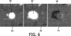
図6において、管状構造(血管)65を通じた断面図の2つの画像は、図5を参照して説明した上述の方法に基づく模範的検査を示しており、すなわち2つの表示62,63の関係が血管65の中心線に沿うパスに沿った距離として規定される。付加的な表示61において、表示62及び63の結果的に得られる減算画像を観察することができる。この情報は、当該面がインタラクティブに再位置づけされながら実時間にて更新可能である。このようにして、例えば、血管の狭窄症を検出するのが容易になる。この場合、付加的表示に呈された情報は、血管の直径の変化を検出することを可能にする。さらに、この変化の勾配、すなわち当該直径がどのぐらい速く変化しているかが提供される。したがって、この勾配のための予め規定された閾値を提供することにより血管の狭窄症を検出することができる。この閾値に交差するとき、これは病理学的な狭窄症の兆候である。
In FIG. 6, the two images of the cross-sectional view through the tubular structure (blood vessel) 65 show an exemplary examination based on the method described above with reference to FIG. 5, ie the relationship between the two
図7及び図8は、さらなる例により付加的な表示を示している。検査される画像表示72,73,82,83において行われる画像解析計算の結果的な画像を表す人が読取可能な装置に表示される付加的表示は、それぞれ画像表示72,82及び画像表示73,83の減算である。図7は、表示72,73を示しており、これらは、人の頭骨を通じるスライスであり人の脳を示している。付加的表示71は、表示72を表示73で減算した後の結果的画像を示している。図8において、表示82,83は、図7と比較して少し回転させられ、結果的に得られる画像が付加的な表示81に示される。
7 and 8 show additional displays by way of further examples. Additional displays displayed on the human-readable device representing the resulting image of the image analysis calculation performed in the
本発明の実施例の1つの可能な応用例は、病理学的な疾患の自動化された判定用とされる。例えば、上述した狭窄症検出を自動化することができる。この場合、血管の局部的曲率が測定され、これが血管の解剖学的経路の検出と、血管を通じる中心線の定義とを可能にする。その後、当該中心線に沿ったもの及びこれに直角なものの2つの表示の関係の自動化された解析を行うことができる。これら表示の間の差(減算)すなわちその減算される画素の強度(濃淡値)及び密度は、血管の経路に沿って狭窄症の存在を示す。これにより、識別される狭窄症の接近度の高い検査を可能にする。 One possible application of an embodiment of the present invention is for automated determination of pathological diseases. For example, the above-described stenosis detection can be automated. In this case, the local curvature of the blood vessel is measured, which allows the detection of the anatomical path of the blood vessel and the definition of the centerline through the blood vessel. Thereafter, an automated analysis of the relationship between the two displays, one along the center line and one perpendicular thereto, can be performed. The difference (subtraction) between these displays, ie, the intensity (shading value) and density of the subtracted pixel, indicates the presence of stenosis along the vessel path. This enables an examination with a high degree of proximity to the identified stenosis.
本発明の方法は、ハードウェア、ソフトウェア、ファームウェア又はこれらの組み合わせを含む適切な形態で実現することができる。但し、変換行列のような画像解析計算及び情報の呈示は、1つ又は複数のデータプロセッサ及び/又はディジタル信号処理器において動作するコンピュータソフトウェアとして実現されるのが好ましい。本発明の実施例の要素及び構成部は、適切な方法で物理的、機能的及び論理的に実現可能である。実際、その機能は、単一のユニットにより、複数のユニットにより、又は他の機能ユニットの一部として実現可能である。それ故、本発明は、単一のユニットで実現可能であり、或いは、異なるユニットと処理器との間で物理的かつ機能的に分散させることができる。 The method of the present invention can be implemented in any suitable form including hardware, software, firmware, or a combination thereof. However, image analysis calculations such as transformation matrices and information presentation are preferably implemented as computer software running on one or more data processors and / or digital signal processors. The elements and components of an embodiment of the invention may be physically, functionally and logically implemented in a suitable way. Indeed, the function can be realized by a single unit, by multiple units or as part of another functional unit. Thus, the present invention can be implemented in a single unit or can be physically and functionally distributed between different units and processors.
本発明による新しい態様で医療用3Dデータ画像表示面を関係づける上述した方法の用途及び使用は、様々であり、医療用3Dデータが処理される全ての分野を含むものである。 The uses and uses of the above-described method for relating medical 3D data image display surfaces in a new manner according to the present invention are varied and include all fields in which medical 3D data is processed.
本発明は、特定の実施例に基づいてこれまで説明してきたが、ここで記載した特定の形態に限定されることを意図するものではない。むしろ、本発明は、添付の請求項によってのみ限定されるものであり、上記特定のもの以外の実施例は、これら添付の請求項の範囲内で等しく可能である。 Although the present invention has been described above with reference to specific embodiments, it is not intended to be limited to the specific form set forth herein. Rather, the invention is limited only by the accompanying claims, and other embodiments than the specific above are equally possible within the scope of these appended claims.
請求項において、「有する/有し」なる文言は、他の要素又はステップの存在を排除するものではない。さらに、個々に列挙してはいるものの、複数の手段、要素又は方法ステップは、例えば単一のユニット又はプロセッサにより実現可能である。また、個々の特徴は異なる請求項に含まれうるものの、これらは効果的に組み合わせ可能なものであり、異なる請求項における包含は、特徴の組み合わせが実現可能なもの及び/又は有利なものではないことを意味するものではない。また、単数の引用は、複数を排除するものではない。「1つの」、「1の」、「第1の」、「第2の」などの文言は、複数を排除するものではない。請求項における参照符号は、明瞭な例として付与されているに過ぎず、多少なりとも請求項の範囲を限定するものと解釈してはならない。 In the claims, the word “comprising / having” does not exclude the presence of other elements or steps. Furthermore, although individually listed, a plurality of means, elements or method steps may be implemented by eg a single unit or processor. Also, although individual features may be included in different claims, they may be effectively combined, and inclusion in different claims is not feasible and / or advantageous for a combination of features. It doesn't mean that. In addition, singular citations do not exclude a plurality. Words such as “one”, “1”, “first”, “second” do not exclude a plurality. Reference signs in the claims are provided merely as a clarifying example and shall not be construed as limiting the scope of the claims in any way.
Claims (12)
・少なくとも1つの3次元(3D)医療画像データセットにおいて少なくとも2つの非直交2次元(2D)画像表示面を規定し、
・前記2D画像表示面を互いにリンクづけし、前記2D画像表示面のうちの第1のものが再位置づけされるとき、その残りの2D画像表示面の各々は、当該再位置づけされた第1の2D画像表示面に対して自動的に再位置づけされるようにする、
方法。A method for relating medical data image display surfaces to each other,
Defining at least two non-orthogonal two-dimensional (2D) image display surfaces in at least one three-dimensional (3D) medical image data set;
When the 2D image display surfaces are linked together and a first one of the 2D image display surfaces is repositioned, each of the remaining 2D image display surfaces is repositioned first To be automatically repositioned with respect to the 2D image display surface,
Method.
・少なくとも1つの3次元(3D)医療画像データセットにおいて少なくとも2つの非直交2次元(2D)画像表示面を規定するための手段と、
・前記2D画像表示面を互いにリンクづけし、前記2D画像表示面のうちの第1のものが再位置づけされるとき、その残りの2D画像表示面の各々が、当該再位置づけされた第1の2D画像表示面に対して自動的に再位置づけされるようにする手段と、
を有するワークステーション。A medical workstation configured to perform the method according to any one of claims 1 to 10 and adapted to relate medical data image display surfaces to each other,
Means for defining at least two non-orthogonal two-dimensional (2D) image display surfaces in at least one three-dimensional (3D) medical image data set;
When the 2D image display surfaces are linked together and a first one of the 2D image display surfaces is repositioned, each of the remaining 2D image display surfaces is repositioned first Means for automatically repositioning relative to the 2D image display surface;
Having a workstation.
・少なくとも1つの3次元(3D)医療画像データセットにおいて少なくとも2つの非直交2次元(2D)画像表示面を規定するための第1のコードセグメントと、
・前記2D画像表示面を互いにリンクづけし、前記2D画像表示面のうちの第1のものが再位置づけされるとき、その残りの2D画像表示面の各々が、当該再位置づけされた第1の2D画像表示面に対して自動的に再位置づけされるようにした第2のコードセグメントと、
を有する、
媒体。A computer readable medium embodying a computer program for associating medical data image display surfaces for processing by a computer, the computer program comprising:
A first code segment for defining at least two non-orthogonal two-dimensional (2D) image display surfaces in at least one three-dimensional (3D) medical image data set;
When the 2D image display surfaces are linked together and a first one of the 2D image display surfaces is repositioned, each of the remaining 2D image display surfaces is repositioned first A second code segment adapted to be automatically repositioned with respect to the 2D image display surface;
Having
Medium.
Applications Claiming Priority (3)
| Application Number | Priority Date | Filing Date | Title |
|---|---|---|---|
| EP05112143 | 2005-12-14 | ||
| EP05112143.2 | 2005-12-14 | ||
| PCT/IB2006/054633 WO2007069144A2 (en) | 2005-12-14 | 2006-12-06 | Method and device for relating medical 3d data image viewing planes to each other |
Publications (3)
| Publication Number | Publication Date |
|---|---|
| JP2009519077A JP2009519077A (en) | 2009-05-14 |
| JP2009519077A5 JP2009519077A5 (en) | 2012-05-17 |
| JP5002599B2 true JP5002599B2 (en) | 2012-08-15 |
Family
ID=38002023
Family Applications (1)
| Application Number | Title | Priority Date | Filing Date |
|---|---|---|---|
| JP2008545176A Active JP5002599B2 (en) | 2005-12-14 | 2006-12-06 | Method and apparatus for relating medical 3D data image display surfaces to each other |
Country Status (7)
| Country | Link |
|---|---|
| US (1) | US8290225B2 (en) |
| EP (1) | EP1964070B1 (en) |
| JP (1) | JP5002599B2 (en) |
| CN (1) | CN101331525B (en) |
| AT (1) | ATE470921T1 (en) |
| DE (1) | DE602006014865D1 (en) |
| WO (1) | WO2007069144A2 (en) |
Families Citing this family (23)
| Publication number | Priority date | Publication date | Assignee | Title |
|---|---|---|---|---|
| JP5319180B2 (en) * | 2007-07-10 | 2013-10-16 | 株式会社東芝 | X-ray imaging apparatus, image processing apparatus, and image processing program |
| EP2162086B1 (en) | 2007-10-01 | 2019-02-27 | Orthosoft Inc. | Construction of a non-imaged view of an object using acquired images |
| JP2011125568A (en) * | 2009-12-18 | 2011-06-30 | Canon Inc | Image processor, image processing method, program and image processing system |
| WO2011097537A2 (en) | 2010-02-04 | 2011-08-11 | University Of Florida Research Foundation,Inc. | Sample point-based, blob-like, closed-surface delineation approach |
| US9053562B1 (en) | 2010-06-24 | 2015-06-09 | Gregory S. Rabin | Two dimensional to three dimensional moving image converter |
| EP2518690A1 (en) * | 2011-04-28 | 2012-10-31 | Koninklijke Philips Electronics N.V. | Medical image processing system and method |
| EP2521098A1 (en) * | 2011-05-06 | 2012-11-07 | Koninklijke Philips Electronics N.V. | Medical image system and method |
| US9196091B2 (en) * | 2012-01-24 | 2015-11-24 | Kabushiki Kaisha Toshiba | Image processing method and system |
| JP5215483B1 (en) * | 2012-02-24 | 2013-06-19 | 株式会社東芝 | Medical image processing device |
| TWI501749B (en) * | 2012-11-26 | 2015-10-01 | Univ Nat Central | Instrument guiding method of surgical navigation system |
| US9992021B1 (en) | 2013-03-14 | 2018-06-05 | GoTenna, Inc. | System and method for private and point-to-point communication between computing devices |
| US10709425B2 (en) | 2013-04-03 | 2020-07-14 | Koninklijke Philips N.V. | 3D ultrasound imaging system |
| US9595088B2 (en) * | 2013-11-20 | 2017-03-14 | Toshiba Medical Systems Corporation | Method of, and apparatus for, visualizing medical image data |
| KR101578770B1 (en) | 2013-11-21 | 2015-12-18 | 삼성전자주식회사 | Apparatus por processing a medical image and method for processing a medical image |
| US8917925B1 (en) * | 2014-03-28 | 2014-12-23 | Heartflow, Inc. | Systems and methods for data and model-driven image reconstruction and enhancement |
| JP6656807B2 (en) * | 2015-02-10 | 2020-03-04 | キヤノンメディカルシステムズ株式会社 | X-ray diagnostic equipment |
| JP6476041B2 (en) * | 2015-03-31 | 2019-02-27 | 株式会社Aze | MEDICAL IMAGE DIAGNOSIS DEVICE, ITS CONTROL METHOD, AND PROGRAM |
| JP6391544B2 (en) * | 2015-09-29 | 2018-09-19 | キヤノン株式会社 | Medical image processing apparatus, medical image processing method, and program |
| EP3178380A1 (en) * | 2015-12-09 | 2017-06-14 | Canon Kabushiki Kaisha | Photoacoustic apparatus, display control method, and program |
| CN107480673B (en) * | 2017-06-30 | 2021-01-26 | 上海联影医疗科技股份有限公司 | Method and device for determining interest region in medical image and image editing system |
| JP6429958B2 (en) * | 2017-08-09 | 2018-11-28 | キヤノン株式会社 | Image processing apparatus, image processing method, and program |
| CN109003471A (en) * | 2018-09-16 | 2018-12-14 | 山东数字人科技股份有限公司 | A kind of 3 D human body supersonic anatomy tutoring system and method |
| CN110989901B (en) * | 2019-11-29 | 2022-01-18 | 北京市商汤科技开发有限公司 | Interactive display method and device for image positioning, electronic equipment and storage medium |
Family Cites Families (15)
| Publication number | Priority date | Publication date | Assignee | Title |
|---|---|---|---|---|
| US4774570A (en) * | 1986-09-20 | 1988-09-27 | Sony Corporation | System for processing video signal for detecting changes in video data and security monitoring system utilizing the same |
| US5270926A (en) * | 1990-12-21 | 1993-12-14 | General Electric Company | Method and apparatus for reconstructing a three-dimensional computerized tomography (CT) image of an object from incomplete cone beam projection data |
| US5458111A (en) | 1994-09-06 | 1995-10-17 | William C. Bond | Computed tomographic colonoscopy |
| JP3496292B2 (en) * | 1994-09-30 | 2004-02-09 | 日本ゼオン株式会社 | Composites of nitrile group-containing highly saturated copolymer rubber and fiber |
| KR0176157B1 (en) * | 1995-08-14 | 1999-05-01 | 김광호 | Cctv having an improved search function and search method suitable for them |
| US5638819A (en) | 1995-08-29 | 1997-06-17 | Manwaring; Kim H. | Method and apparatus for guiding an instrument to a target |
| US5971767A (en) * | 1996-09-16 | 1999-10-26 | The Research Foundation Of State University Of New York | System and method for performing a three-dimensional virtual examination |
| US6064904A (en) | 1997-11-28 | 2000-05-16 | Picker International, Inc. | Frameless stereotactic CT scanner with virtual needle display for planning image guided interventional procedures |
| US6898302B1 (en) * | 1999-05-21 | 2005-05-24 | Emory University | Systems, methods and computer program products for the display and visually driven definition of tomographic image planes in three-dimensional space |
| US6671538B1 (en) | 1999-11-26 | 2003-12-30 | Koninklijke Philips Electronics, N.V. | Interface system for use with imaging devices to facilitate visualization of image-guided interventional procedure planning |
| US6970594B2 (en) * | 2002-01-22 | 2005-11-29 | Siemens Corporate Research, Inc. | Visualization imaging system for curvilinear structures |
| FR2835949B1 (en) * | 2002-02-08 | 2004-07-09 | Commissariat Energie Atomique | TOMOSYNTHESIS METHOD WITH MULTIPLAN RECONSTRUCTION |
| US20050065424A1 (en) * | 2003-06-06 | 2005-03-24 | Ge Medical Systems Information Technologies, Inc. | Method and system for volumemetric navigation supporting radiological reading in medical imaging systems |
| US20050101864A1 (en) * | 2003-10-23 | 2005-05-12 | Chuan Zheng | Ultrasound diagnostic imaging system and method for 3D qualitative display of 2D border tracings |
| US7496222B2 (en) * | 2005-06-23 | 2009-02-24 | General Electric Company | Method to define the 3D oblique cross-section of anatomy at a specific angle and be able to easily modify multiple angles of display simultaneously |
-
2006
- 2006-12-06 JP JP2008545176A patent/JP5002599B2/en active Active
- 2006-12-06 US US12/097,112 patent/US8290225B2/en active Active
- 2006-12-06 DE DE602006014865T patent/DE602006014865D1/en active Active
- 2006-12-06 AT AT06832118T patent/ATE470921T1/en not_active IP Right Cessation
- 2006-12-06 EP EP06832118A patent/EP1964070B1/en active Active
- 2006-12-06 CN CN200680046771.8A patent/CN101331525B/en active Active
- 2006-12-06 WO PCT/IB2006/054633 patent/WO2007069144A2/en active Application Filing
Also Published As
| Publication number | Publication date |
|---|---|
| ATE470921T1 (en) | 2010-06-15 |
| US8290225B2 (en) | 2012-10-16 |
| JP2009519077A (en) | 2009-05-14 |
| CN101331525B (en) | 2013-03-27 |
| DE602006014865D1 (en) | 2010-07-22 |
| WO2007069144A3 (en) | 2007-09-20 |
| CN101331525A (en) | 2008-12-24 |
| WO2007069144A2 (en) | 2007-06-21 |
| EP1964070B1 (en) | 2010-06-09 |
| US20090169076A1 (en) | 2009-07-02 |
| EP1964070A2 (en) | 2008-09-03 |
Similar Documents
| Publication | Publication Date | Title |
|---|---|---|
| JP5002599B2 (en) | Method and apparatus for relating medical 3D data image display surfaces to each other | |
| JP4829217B2 (en) | Data set visualization | |
| US8625869B2 (en) | Visualization of medical image data with localized enhancement | |
| US8009167B2 (en) | Virtual endoscopy | |
| CN101203889B (en) | Method for visualizing cutaway section of bending drawing structure | |
| US20070167762A1 (en) | Ultrasound system for interventional treatment | |
| US6983063B1 (en) | Computer-aided diagnosis method for aiding diagnosis of three dimensional digital image data | |
| US20080117210A1 (en) | Virtual endoscopy | |
| WO2008069933A1 (en) | Analyzing lesions in a medical digital image | |
| Bauer et al. | Virtual bronchoscopy: clinical applications and limitations | |
| JP2007061622A (en) | System and method for automated airway evaluation for multi-slice computed tomography (msct) image data using airway lumen diameter, airway wall thickness and broncho-arterial ratio | |
| JP4686279B2 (en) | Medical diagnostic apparatus and diagnostic support apparatus | |
| JP2007222626A (en) | Automatic detecting method and device for unique part in medical image data | |
| US7489809B2 (en) | Interactive virtual endoscopy | |
| JP2005349199A (en) | Medical three-dimensional image display, three-dimensional image processing method, computer tomographic apparatus, work station and computer program product | |
| Silva et al. | Three-dimensional virtual dissection at CT colonography: unraveling the colon to search for lesions | |
| Nagelhus Hernes et al. | Computer‐assisted 3D ultrasound‐guided neurosurgery: technological contributions, including multimodal registration and advanced display, demonstrating future perspectives | |
| US8115760B2 (en) | Pictorial representation of three-dimensional data records | |
| US20120188240A1 (en) | Medical image display apparatus, method and program | |
| WO2012038863A1 (en) | Quantification of a characteristic of a lumen of a tubular structure | |
| US20110285695A1 (en) | Pictorial Representation in Virtual Endoscopy | |
| Furlow | CT image visualization: a conceptual introduction | |
| Kumar et al. | Virtual colonoscopy: A plausible alternative to conventional colonoscopy | |
| McLennan et al. | Virtual bronchoscopy | |
| Wesarg | Supporting the TECAB grafting through CT based analysis of coronary arteries |
Legal Events
| Date | Code | Title | Description |
|---|---|---|---|
| A621 | Written request for application examination |
Free format text: JAPANESE INTERMEDIATE CODE: A621 Effective date: 20091203 |
|
| A131 | Notification of reasons for refusal |
Free format text: JAPANESE INTERMEDIATE CODE: A131 Effective date: 20120202 |
|
| A524 | Written submission of copy of amendment under article 19 pct |
Free format text: JAPANESE INTERMEDIATE CODE: A524 Effective date: 20120326 |
|
| TRDD | Decision of grant or rejection written | ||
| A01 | Written decision to grant a patent or to grant a registration (utility model) |
Free format text: JAPANESE INTERMEDIATE CODE: A01 Effective date: 20120424 |
|
| A01 | Written decision to grant a patent or to grant a registration (utility model) |
Free format text: JAPANESE INTERMEDIATE CODE: A01 |
|
| A61 | First payment of annual fees (during grant procedure) |
Free format text: JAPANESE INTERMEDIATE CODE: A61 Effective date: 20120521 |
|
| R150 | Certificate of patent or registration of utility model |
Ref document number: 5002599 Country of ref document: JP Free format text: JAPANESE INTERMEDIATE CODE: R150 Free format text: JAPANESE INTERMEDIATE CODE: R150 |
|
| FPAY | Renewal fee payment (event date is renewal date of database) |
Free format text: PAYMENT UNTIL: 20150525 Year of fee payment: 3 |
|
| R250 | Receipt of annual fees |
Free format text: JAPANESE INTERMEDIATE CODE: R250 |
|
| R250 | Receipt of annual fees |
Free format text: JAPANESE INTERMEDIATE CODE: R250 |
|
| R250 | Receipt of annual fees |
Free format text: JAPANESE INTERMEDIATE CODE: R250 |
|
| R250 | Receipt of annual fees |
Free format text: JAPANESE INTERMEDIATE CODE: R250 |
|
| R250 | Receipt of annual fees |
Free format text: JAPANESE INTERMEDIATE CODE: R250 |
|
| R250 | Receipt of annual fees |
Free format text: JAPANESE INTERMEDIATE CODE: R250 |
|
| R250 | Receipt of annual fees |
Free format text: JAPANESE INTERMEDIATE CODE: R250 |
|
| R250 | Receipt of annual fees |
Free format text: JAPANESE INTERMEDIATE CODE: R250 |
|
| R250 | Receipt of annual fees |
Free format text: JAPANESE INTERMEDIATE CODE: R250 |