JP5002453B2 - Methods and equipment with improved ventilation support cycle - Google Patents
Methods and equipment with improved ventilation support cycle Download PDFInfo
- Publication number
- JP5002453B2 JP5002453B2 JP2007516889A JP2007516889A JP5002453B2 JP 5002453 B2 JP5002453 B2 JP 5002453B2 JP 2007516889 A JP2007516889 A JP 2007516889A JP 2007516889 A JP2007516889 A JP 2007516889A JP 5002453 B2 JP5002453 B2 JP 5002453B2
- Authority
- JP
- Japan
- Prior art keywords
- ventilator
- threshold
- cycle
- inspiration
- time
- Prior art date
- Legal status (The legal status is an assumption and is not a legal conclusion. Google has not performed a legal analysis and makes no representation as to the accuracy of the status listed.)
- Expired - Fee Related
Links
- 238000000034 method Methods 0.000 title description 15
- 238000009423 ventilation Methods 0.000 title description 7
- 230000003434 inspiratory effect Effects 0.000 claims description 35
- 230000035945 sensitivity Effects 0.000 claims description 22
- 230000000241 respiratory effect Effects 0.000 claims description 20
- 230000029058 respiratory gaseous exchange Effects 0.000 claims description 18
- 230000001965 increasing effect Effects 0.000 claims description 12
- 230000006870 function Effects 0.000 description 22
- 230000036279 refractory period Effects 0.000 description 12
- 230000008569 process Effects 0.000 description 7
- 230000008859 change Effects 0.000 description 4
- 230000000763 evoking effect Effects 0.000 description 3
- 238000012544 monitoring process Methods 0.000 description 3
- 230000004044 response Effects 0.000 description 3
- 230000001360 synchronised effect Effects 0.000 description 3
- 230000007704 transition Effects 0.000 description 3
- 208000006545 Chronic Obstructive Pulmonary Disease Diseases 0.000 description 2
- 230000001351 cycling effect Effects 0.000 description 2
- 230000007246 mechanism Effects 0.000 description 2
- 206010011224 Cough Diseases 0.000 description 1
- 208000004756 Respiratory Insufficiency Diseases 0.000 description 1
- 230000002159 abnormal effect Effects 0.000 description 1
- 238000013459 approach Methods 0.000 description 1
- 230000002051 biphasic effect Effects 0.000 description 1
- 238000013500 data storage Methods 0.000 description 1
- 238000010586 diagram Methods 0.000 description 1
- 238000005259 measurement Methods 0.000 description 1
- 238000012986 modification Methods 0.000 description 1
- 230000004048 modification Effects 0.000 description 1
- 201000004193 respiratory failure Diseases 0.000 description 1
- 230000004202 respiratory function Effects 0.000 description 1
- 230000036387 respiratory rate Effects 0.000 description 1
- 201000002859 sleep apnea Diseases 0.000 description 1
- 230000002269 spontaneous effect Effects 0.000 description 1
- 230000001960 triggered effect Effects 0.000 description 1
- 230000003519 ventilatory effect Effects 0.000 description 1
Images


Classifications
-
- A—HUMAN NECESSITIES
- A61—MEDICAL OR VETERINARY SCIENCE; HYGIENE
- A61M—DEVICES FOR INTRODUCING MEDIA INTO, OR ONTO, THE BODY; DEVICES FOR TRANSDUCING BODY MEDIA OR FOR TAKING MEDIA FROM THE BODY; DEVICES FOR PRODUCING OR ENDING SLEEP OR STUPOR
- A61M16/00—Devices for influencing the respiratory system of patients by gas treatment, e.g. mouth-to-mouth respiration; Tracheal tubes
- A61M16/0057—Pumps therefor
- A61M16/0066—Blowers or centrifugal pumps
- A61M16/0069—Blowers or centrifugal pumps the speed thereof being controlled by respiratory parameters, e.g. by inhalation
-
- A—HUMAN NECESSITIES
- A61—MEDICAL OR VETERINARY SCIENCE; HYGIENE
- A61M—DEVICES FOR INTRODUCING MEDIA INTO, OR ONTO, THE BODY; DEVICES FOR TRANSDUCING BODY MEDIA OR FOR TAKING MEDIA FROM THE BODY; DEVICES FOR PRODUCING OR ENDING SLEEP OR STUPOR
- A61M16/00—Devices for influencing the respiratory system of patients by gas treatment, e.g. mouth-to-mouth respiration; Tracheal tubes
- A61M16/0003—Accessories therefor, e.g. sensors, vibrators, negative pressure
-
- A—HUMAN NECESSITIES
- A61—MEDICAL OR VETERINARY SCIENCE; HYGIENE
- A61M—DEVICES FOR INTRODUCING MEDIA INTO, OR ONTO, THE BODY; DEVICES FOR TRANSDUCING BODY MEDIA OR FOR TAKING MEDIA FROM THE BODY; DEVICES FOR PRODUCING OR ENDING SLEEP OR STUPOR
- A61M16/00—Devices for influencing the respiratory system of patients by gas treatment, e.g. mouth-to-mouth respiration; Tracheal tubes
- A61M16/0051—Devices for influencing the respiratory system of patients by gas treatment, e.g. mouth-to-mouth respiration; Tracheal tubes with alarm devices
-
- A—HUMAN NECESSITIES
- A61—MEDICAL OR VETERINARY SCIENCE; HYGIENE
- A61M—DEVICES FOR INTRODUCING MEDIA INTO, OR ONTO, THE BODY; DEVICES FOR TRANSDUCING BODY MEDIA OR FOR TAKING MEDIA FROM THE BODY; DEVICES FOR PRODUCING OR ENDING SLEEP OR STUPOR
- A61M16/00—Devices for influencing the respiratory system of patients by gas treatment, e.g. mouth-to-mouth respiration; Tracheal tubes
- A61M16/021—Devices for influencing the respiratory system of patients by gas treatment, e.g. mouth-to-mouth respiration; Tracheal tubes operated by electrical means
- A61M16/022—Control means therefor
- A61M16/024—Control means therefor including calculation means, e.g. using a processor
-
- A—HUMAN NECESSITIES
- A61—MEDICAL OR VETERINARY SCIENCE; HYGIENE
- A61M—DEVICES FOR INTRODUCING MEDIA INTO, OR ONTO, THE BODY; DEVICES FOR TRANSDUCING BODY MEDIA OR FOR TAKING MEDIA FROM THE BODY; DEVICES FOR PRODUCING OR ENDING SLEEP OR STUPOR
- A61M16/00—Devices for influencing the respiratory system of patients by gas treatment, e.g. mouth-to-mouth respiration; Tracheal tubes
- A61M16/06—Respiratory or anaesthetic masks
-
- A—HUMAN NECESSITIES
- A61—MEDICAL OR VETERINARY SCIENCE; HYGIENE
- A61M—DEVICES FOR INTRODUCING MEDIA INTO, OR ONTO, THE BODY; DEVICES FOR TRANSDUCING BODY MEDIA OR FOR TAKING MEDIA FROM THE BODY; DEVICES FOR PRODUCING OR ENDING SLEEP OR STUPOR
- A61M16/00—Devices for influencing the respiratory system of patients by gas treatment, e.g. mouth-to-mouth respiration; Tracheal tubes
- A61M16/0003—Accessories therefor, e.g. sensors, vibrators, negative pressure
- A61M2016/0015—Accessories therefor, e.g. sensors, vibrators, negative pressure inhalation detectors
- A61M2016/0018—Accessories therefor, e.g. sensors, vibrators, negative pressure inhalation detectors electrical
- A61M2016/0021—Accessories therefor, e.g. sensors, vibrators, negative pressure inhalation detectors electrical with a proportional output signal, e.g. from a thermistor
-
- A—HUMAN NECESSITIES
- A61—MEDICAL OR VETERINARY SCIENCE; HYGIENE
- A61M—DEVICES FOR INTRODUCING MEDIA INTO, OR ONTO, THE BODY; DEVICES FOR TRANSDUCING BODY MEDIA OR FOR TAKING MEDIA FROM THE BODY; DEVICES FOR PRODUCING OR ENDING SLEEP OR STUPOR
- A61M16/00—Devices for influencing the respiratory system of patients by gas treatment, e.g. mouth-to-mouth respiration; Tracheal tubes
- A61M16/0003—Accessories therefor, e.g. sensors, vibrators, negative pressure
- A61M2016/0027—Accessories therefor, e.g. sensors, vibrators, negative pressure pressure meter
-
- A—HUMAN NECESSITIES
- A61—MEDICAL OR VETERINARY SCIENCE; HYGIENE
- A61M—DEVICES FOR INTRODUCING MEDIA INTO, OR ONTO, THE BODY; DEVICES FOR TRANSDUCING BODY MEDIA OR FOR TAKING MEDIA FROM THE BODY; DEVICES FOR PRODUCING OR ENDING SLEEP OR STUPOR
- A61M16/00—Devices for influencing the respiratory system of patients by gas treatment, e.g. mouth-to-mouth respiration; Tracheal tubes
- A61M16/0003—Accessories therefor, e.g. sensors, vibrators, negative pressure
- A61M2016/003—Accessories therefor, e.g. sensors, vibrators, negative pressure with a flowmeter
- A61M2016/0033—Accessories therefor, e.g. sensors, vibrators, negative pressure with a flowmeter electrical
- A61M2016/0036—Accessories therefor, e.g. sensors, vibrators, negative pressure with a flowmeter electrical in the breathing tube and used in both inspiratory and expiratory phase
-
- A—HUMAN NECESSITIES
- A61—MEDICAL OR VETERINARY SCIENCE; HYGIENE
- A61M—DEVICES FOR INTRODUCING MEDIA INTO, OR ONTO, THE BODY; DEVICES FOR TRANSDUCING BODY MEDIA OR FOR TAKING MEDIA FROM THE BODY; DEVICES FOR PRODUCING OR ENDING SLEEP OR STUPOR
- A61M16/00—Devices for influencing the respiratory system of patients by gas treatment, e.g. mouth-to-mouth respiration; Tracheal tubes
- A61M16/0003—Accessories therefor, e.g. sensors, vibrators, negative pressure
- A61M2016/003—Accessories therefor, e.g. sensors, vibrators, negative pressure with a flowmeter
- A61M2016/0033—Accessories therefor, e.g. sensors, vibrators, negative pressure with a flowmeter electrical
- A61M2016/0039—Accessories therefor, e.g. sensors, vibrators, negative pressure with a flowmeter electrical in the inspiratory circuit
-
- A—HUMAN NECESSITIES
- A61—MEDICAL OR VETERINARY SCIENCE; HYGIENE
- A61M—DEVICES FOR INTRODUCING MEDIA INTO, OR ONTO, THE BODY; DEVICES FOR TRANSDUCING BODY MEDIA OR FOR TAKING MEDIA FROM THE BODY; DEVICES FOR PRODUCING OR ENDING SLEEP OR STUPOR
- A61M2205/00—General characteristics of the apparatus
- A61M2205/33—Controlling, regulating or measuring
- A61M2205/3303—Using a biosensor
-
- A—HUMAN NECESSITIES
- A61—MEDICAL OR VETERINARY SCIENCE; HYGIENE
- A61M—DEVICES FOR INTRODUCING MEDIA INTO, OR ONTO, THE BODY; DEVICES FOR TRANSDUCING BODY MEDIA OR FOR TAKING MEDIA FROM THE BODY; DEVICES FOR PRODUCING OR ENDING SLEEP OR STUPOR
- A61M2205/00—General characteristics of the apparatus
- A61M2205/50—General characteristics of the apparatus with microprocessors or computers
Description
本発明は、被検者の呼吸サイクルと同期する換気支援を与えるための方法及び機器に関する。より具体的には、本発明は、人工呼吸器を同期させ、人工呼吸器の圧力応答を患者の呼吸サイクルと連動してサイクルさせるための方法に関する。 The present invention relates to a method and apparatus for providing ventilatory assistance in synchronization with a subject's respiratory cycle. More specifically, the present invention relates to a method for synchronizing a ventilator and cycling the ventilator's pressure response in conjunction with the patient's respiratory cycle.
本発明は、呼吸流量がサイクルのために使用される任意の形態の換気に対して適用できるが、主に非侵襲的な圧力サポート換気において有用である。また、本発明は、特に圧力サポートの類の侵襲的な換気にも用途を見出す。本発明は、一般に睡眠時無呼吸を有さないが呼吸機能不足又は呼吸不全を伴う患者に関し、高レベル圧力サポートの存在下で最も大きな用途を見出す。その場合、換気支援は、一般的には主に夜に与えられるが、昼間のある時間中に十分に与えられてもよい。特に慢性閉塞性肺疾患(COPD)において、呼吸の仕組みが異常であると、サイクルが顕著な問題となる。 The present invention is applicable to any form of ventilation where respiratory flow is used for the cycle, but is primarily useful in non-invasive pressure support ventilation. The present invention also finds application in invasive ventilation, especially of the kind of pressure support. The present invention generally relates to patients who do not have sleep apnea but have poor respiratory function or respiratory failure and find the greatest use in the presence of high level pressure support. In that case, ventilation assistance is generally given mainly at night, but may be given well during some time of day. In particular, in chronic obstructive pulmonary disease (COPD), if the breathing mechanism is abnormal, the cycle becomes a significant problem.
人工呼吸器においては、人工呼吸器が適切な換気応答を行うことができるように、患者の実際の呼吸サイクルが吸気から呼気へ又はその逆へ切り換わる時期を検出するための制御プロセスを有することがしばしば必要となる。例えば、幾つかの換気装置は、患者の呼吸サイクルの吸気部分の間にわたって適切な圧力を供給するために吸気圧力をトリガする時期を決定するためのプロセスを行う。同様に、このような装置は、患者の呼気中に適切な機械−患者応答を供給するために呼気圧力へとサイクルさせる時期を決定するためのプロセスを有している場合もある。このようなプロセスは、人工呼吸器を患者の実際の呼吸サイクルと同期させる働きをする。当業者であれば分かるように、「トリガ」は、患者の吸気を目的とする圧力レベルの開始に関連付けられる事象であり、また、「サイクル」は、患者の呼気を目的とする圧力レベルへの切り換えに関連付けられる事象である。 In a ventilator, have a control process to detect when the patient's actual breathing cycle switches from inspiration to expiration or vice versa so that the ventilator can make an adequate ventilation response Is often required. For example, some ventilators perform a process to determine when to trigger inspiratory pressure to provide the proper pressure during the inspiratory portion of the patient's respiratory cycle. Similarly, such devices may have a process for determining when to cycle to exhalation pressure to provide an appropriate machine-patient response during patient exhalation. Such a process serves to synchronize the ventilator with the patient's actual respiratory cycle. As will be appreciated by those skilled in the art, a “trigger” is an event associated with the onset of a pressure level intended for patient inspiration, and a “cycle” is a pressure level intended for patient exhalation. An event associated with switching.
例えば、二相性人工呼吸器は、患者の呼吸サイクルの吸気部分、いわゆるIPAP中に高圧レベルを供給するとともに、呼吸サイクルの呼気部分、いわゆるEPAP中に低圧レベルを供給する。従来から、切り換えは、呼吸流量又は圧力を監視し且つゼロやピーク流量のパーセンテージなどの閾値レベルを規定することによって行われる場合がある。測定された呼吸流量値が閾値を下回ると、装置はEPAPを遂行する。このような切り換えに代わる他の手段は、呼吸速度の記録及び吸気の開始からの経過時間の監視を伴っていてもよい。この場合、機械は、呼吸サイクルの吸気部分のための期待時間である時間に達した後、呼吸サイクルの呼気部分に切り換えてもよい。 For example, a biphasic ventilator provides a high pressure level during the inspiratory portion of a patient's respiratory cycle, so-called IPAP, and a low pressure level during the expiratory portion of the respiratory cycle, so-called EPAP. Traditionally, switching may be done by monitoring respiratory flow or pressure and defining threshold levels such as zero or percentage of peak flow. If the measured respiratory flow value falls below the threshold, the device performs EPAP. Other means for such switching may involve recording the respiratory rate and monitoring the time elapsed since the start of inspiration. In this case, the machine may switch to the expiratory portion of the respiratory cycle after reaching a time that is the expected time for the inspiratory portion of the respiratory cycle.
サイクルのためのこれらのプロセスの目的は、人工呼吸器をユーザにとって更に快適なものにすることである。なぜなら、呼吸事象が適切に同期されないと、装置が患者にとって非常に不快なものとなり得るからである。更に極めて重要な目的は、特に深刻な呼気流量制限を伴うCOPDにおけるガス交換を最適化して、動的過膨脹を引き起こす長い吸気時間を回避することである。サイクルのためのこの方法は、時として呼気を不適切に検出する可能性があり、それにより不適切な圧力変化をもたらす。例えば、人工呼吸器が非常に早期に呼気へとサイクルする場合には、吸気中にサポートを必要とするときに患者に対してサポートが殆ど行われない。したがって、不適切な同期化を最小限に抑えることによりこのようなプロセスを改善することが必要である。 The purpose of these processes for the cycle is to make the ventilator more comfortable for the user. This is because if the respiratory events are not properly synchronized, the device can be very uncomfortable for the patient. An even more important objective is to optimize gas exchange in COPD with particularly severe expiratory flow restriction to avoid long inspiration times that cause dynamic overexpansion. This method for cycling can sometimes improperly detect exhalation, thereby resulting in inappropriate pressure changes. For example, if the ventilator cycles to exhalation very early, little support is provided to the patient when they need support during inspiration. Therefore, there is a need to improve such processes by minimizing improper synchronization.
本発明の目的は、時間に応じて変化する可変サイクル閾値を与えることにより同期化を向上させることである。 It is an object of the present invention to improve synchronization by providing a variable cycle threshold that varies with time.
本発明の更なる目的は、吸気中にサイクルが進行するにつれて感度が高くなるように変化する同期呼気閾値を与えることである。 It is a further object of the present invention to provide a synchronous expiratory threshold that changes to become more sensitive as the cycle progresses during inspiration.
更なる目的は、本発明の以下の説明を考慮することにより当業者には明らかとなる。 Further objects will become apparent to those skilled in the art upon consideration of the following description of the invention.
本発明では、人工呼吸器が吸気から呼気へと進むべきかどうかを決定するために、流量の指標と比較される同期閾値が計算される。好ましい実施形態において、閾値は、時間の関数であり、1つの吸気サイクル内でサイクルの初期段階中の低感度閾値からサイクルの後期段階中の更に高い感度へと変化することができる。本発明の一実施形態において、閾値には、1サイクル内の特定の時間中に呼気への移行をこのような移行が望ましくなく、又は患者の呼気への実際の進行を正確に反映する可能性が低いときに妨げるための不応期間が与えられる。本発明の更なる態様を以下の明細書で詳細に説明する。 In the present invention, a synchronization threshold is calculated that is compared to the flow rate index to determine if the ventilator should go from inspiration to expiration. In a preferred embodiment, the threshold is a function of time and can vary within a single inspiratory cycle from a low sensitivity threshold during the initial phase of the cycle to a higher sensitivity during the late phase of the cycle. In one embodiment of the present invention, the threshold may reflect the transition to exhalation during a particular time in a cycle, such transition is undesirable or may accurately reflect the actual progression of the patient to exhalation. A refractory period is provided to prevent when low. Further aspects of the invention are described in detail in the following specification.
図1を参照すると、圧力供給装置は、サーボ制御ブロワ2と、マスク6と、ブロワ2とマスク6との間を接続するための空気供給管路8とを含んでいる。排気ガスは排気口13を介して放出される。場合によって、流量センサ4f及び/又は圧力センサ4pが利用されてもよく、その場合には、流量信号F(t)を得るために、呼吸流量図及び差圧トランスデューサ又は同様の装置を使用してマスク流量が測定されてもよく、また、圧力信号Pmask(t)を得るために、圧力トランスデューサを使用して圧力タップでマスク圧力が測定される。当業者であれば流量及び圧力の測定方法を理解していることは言うまでもないため、図1には圧力センサ4f及び流量センサ4pだけが象徴的に示されている。圧力要求信号Prequest(t)を得るために、流量信号F(t)及び圧力信号Pmask(t)はコントローラ又はマイクロプロセッサ15へ送られる。あるいは、米国特許第5,740,795号、第6,332,463号又は第6,237,593号に開示されるように、前述した流量センサや圧力センサを設けることなく、モータに供給される電流及び/又はモータの速度を監視することにより、流量信号F(t)及び圧力信号Pmask(t)がブロワモータに関して評価され、又は計算されてもよい。場合によって、ブロワモータ速度がほぼ一定に保持されてもよく、また、気流をマスクへ方向変換させ、あるいは供給することができるサーボバルブの開放を制御することによりマスク内の圧力が変化されてもよい
Referring to FIG. 1, the pressure supply device includes a
コントローラ15又はプロセッサは、本明細書で詳細に説明する方法論を実行するように構成されて適合されており、また、集積チップ、メモリ及び/又は他の命令又はデータ記憶媒体を含んでいてもよい。例えば、制御方法を伴うプログラム命令が、装置のメモリ中の集積チップにコード化され、あるいは、ソフトウェアとしてロードされてもよい。
The
好ましくは、装置は、一般に呼気中よりも吸気中において高い様々な圧力レベルの連続気道陽圧を供給する。しかしながら、本明細書で説明する本発明の制御原理にしたがって、他の更に快適な様々な自然患者同期圧力変化などの他のタイプの換気圧処置が機器内で実施されてもよい。 Preferably, the device provides continuous positive airway pressure at various pressure levels, generally higher during inspiration than during expiration. However, other types of ventilation pressure procedures, such as various more comfortable natural patient-synchronized pressure changes, may be performed in the device in accordance with the control principles of the present invention described herein.
本発明の原理にしたがって、同期閾値は、1つの吸気呼吸サイクル内で時間に応じて変化する。すなわち、閾値は、サイクル中にわたって一定のままではない。むしろ、閾値が経時的に増大し、それにより、閾値が吸気サイクル中に更に高感度となり、そのため、閾値により、結果として、吸気サイクルが呼気まで進むときに人工呼吸器がサイクルし易くなる。例えば、可変サイクル閾値は、吸気時間が経過するときに装置により連続的に計算されてもよく、また、その期間中に閾値を下回る流量降下により呼気が検出されるまで変化することができる。本発明を眺める他の方法は、吸気が進行するにつれてサイクルの開始に対して人工呼吸器の感度が益々高くなるという方法である。 In accordance with the principles of the present invention, the synchronization threshold varies with time within one inspiratory breathing cycle. That is, the threshold does not remain constant throughout the cycle. Rather, the threshold increases over time, thereby making the threshold more sensitive during the inspiratory cycle, so that the threshold results in the ventilator being more likely to cycle as the inspiratory cycle proceeds to exhalation. For example, the variable cycle threshold may be calculated continuously by the device as the inspiratory time elapses, and may change until expiration is detected due to a flow drop below the threshold during that period. Another way of looking at the present invention is that the ventilator becomes increasingly sensitive to the start of the cycle as inspiration progresses.
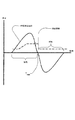
本発明の1つの実施例が図2に示されている。図中、呼気を検出するためのサイクル閾値関数(破線で示される)は、吸気の過程中に低感度から高感度へと変化される。この感度の増大は同期化を向上させる。なぜなら、そのようにサイクル中に閾値が変動すると、装置が吸気の早い段階で呼気へと誤って切り換わってしまう可能性が低いが、吸気が進むにつれて閾値により人工呼吸器が呼気へと切り換わる可能性が高くなるからである。すなわち、吸気の初期部分の間にわたってサイクルすることは難しく、吸気の後期部分の間にわたってサイクルすることは容易である。 One embodiment of the present invention is shown in FIG. In the figure, the cycle threshold function (indicated by a broken line) for detecting exhalation is changed from low sensitivity to high sensitivity during the inspiration process. This increase in sensitivity improves synchronization. Because if the threshold fluctuates during the cycle, the device is unlikely to accidentally switch to exhalation early in inspiration, but the ventilator switches to exhalation as the inspiration progresses This is because the possibility increases. That is, it is difficult to cycle over the early part of inspiration and it is easy to cycle over the late part of inspiration.
本実施形態において、閾値は、吸気の期待時間であることが好ましい時間Tmaxに応じて変化する。また、場合によって、閾値は、最小閾値及び/又は最大閾値の間で変化するように制限されてもよい。一実施形態において、最大閾値及び最小閾値は、ピーク流量、例えばそれぞれ50%及び10%などのある割合又はパーセンテージの前の呼吸のピーク流量の関数であってもよい。あるいは、最大閾値及び最小閾値は、流量測定に基づくゼロよりも大きい何らかの所定の固定された大きさであってもよい。臨床医又は医師がこれらのパーセンテージ又は大きさを選択してもよい。 In the present embodiment, the threshold value changes according to a time T max that is preferably an expected time of inspiration. Also, in some cases, the threshold may be limited to change between a minimum threshold and / or a maximum threshold. In one embodiment, the maximum and minimum thresholds may be a function of peak flow, eg, a peak flow rate of previous breaths, such as a percentage or percentage, such as 50% and 10%, respectively. Alternatively, the maximum and minimum thresholds may be some predetermined fixed magnitude that is greater than zero based on flow measurements. The clinician or physician may select these percentages or sizes.
最大値と最小値との間で、閾値は、経過吸気時間の増加関数などの増加関数であることが好ましい。例えば、増加関数は、期待吸気時間Tmaxに対する経過吸気時間(Tinsp_elapsed)の比率(例えば、k×Tinsp_elapsed/Tmax)であってもよい。ここで、kは、感度の高速増大を必要とする患者が高速サイクルを必要とする患者のための更に速い呼気へのサイクルを行えるように更に高く調整できる予め設定された感度定数である。一実施形態において、Tmaxすなわち期待吸気時間は、前の呼吸から、例えば前の5つの正常な呼吸(例えば咳を除く)からの平均吸気時間として決定される。あるいは、Tmaxは、予め設定された最大吸気サイクル時間であってもよい。経過吸気時間Tinsp_elapsedカウンタは、呼気中に0に設定することができるとともに、吸気の初めにカウントをし始める。例えば、閾値が以下のように設定されてもよい。
Temp_Threshold=(k×Tinsp_elapsed/Tmax)×max_threshold
Temp_Threshold<min_thresholdである場合には、
閾値をmin_thresholdに設定する。
Temp_Threshold>max_thresholdである場合には、
閾値をmax_threshold に設定する。
それ以外の場合には、
閾値をTemp_Thresholdに設定する。
Between the maximum and minimum values, the threshold is preferably an increasing function such as an increasing function of the elapsed inspiratory time. For example, increasing function may be a ratio of the elapsed inspiratory time for the expected inspiratory time T max (T insp _ elapsed) ( e.g., k × T insp _ elapsed / T max). Here, k is a preset sensitivity constant that can be adjusted higher so that patients who need a fast increase in sensitivity can cycle to a faster breath for those who need a fast cycle. In one embodiment, T max or expected inspiration time is determined as the average inspiration time from the previous breath, eg, from the previous five normal breaths (eg, excluding cough). Alternatively, T max may be a preset maximum inspiratory cycle time. Elapsed inspiration time T insp _ elapsed The counter, it is possible to set to zero during exhalation, it starts counting at the beginning of inspiration. For example, the threshold value may be set as follows.
Temp _ Threshold = (k × T insp _ elapsed / T max) × max_threshold
In the case of Temp _ Threshold <min _ threshold is,
Setting the threshold to min _ threshold.
In the case of Temp _ Threshold> max _ threshold is,
Setting the threshold to the max _ threshold.
Otherwise,
The threshold is set to Temp _ Threshold.
吸気時間に応じてサイクル閾値を変えるために他の代わりの方式が利用されてもよい。例えば、同期閾値は、(a)期待吸気期間の最初の部分の間にわたって、例えば期待サイクル時間の約25%の間にわたって最小閾値に設定され、(b)期待吸気期間の中間部分の間(例えば期待吸気サイクル時間の次の約50%の間)にわたって最小値から最大値へと至る勾配をもって設定され、(c)期待吸気期間の最後の部分の間(例えば期待サイクル時間の最後の約25%の間)にわたって最大閾値に設定されてもよい。このような機能は、図2Bのグラフによって示される閾値乗数関数又は閾値感度関数によって実施されてもよい。図2Bの関数を利用して、サイクルのための同期閾値が以下の式によって計算されてもよい。
Threshold=Ts(t)×Peak_Flow
ここで、Ts(t)は、図2Bのグラフによって示されるような0〜1の乗数をもたらす吸気サイクル時間の閾値感度関数であり、
Peak_Flowはピーク吸気流量である。
Other alternative schemes may be used to change the cycle threshold depending on the inspiratory time. For example, the synchronization threshold is set to a minimum threshold during (a) the first part of the expected inspiratory period, eg, about 25% of the expected cycle time, and (b) during the middle part of the expected inspiratory period (eg, Set with a slope from a minimum value to a maximum value over the next approximately 50% of the expected inspiratory cycle time (c) during the last part of the expected inspiratory period (e.g. approximately the last approximately 25% of the expected cycle time May be set to the maximum threshold. Such a function may be implemented by a threshold multiplier function or a threshold sensitivity function illustrated by the graph of FIG. 2B. Using the function of FIG. 2B, the synchronization threshold for the cycle may be calculated by the following equation:
Threshold = Ts (t) × Peak_Flow
Where Ts (t) is the threshold sensitivity function of the inspiratory cycle time resulting in a multiplier of 0-1 as shown by the graph in FIG.
Peak_Flow is a peak intake flow rate.
図2Bに示されたグラフでは、吸気サイクルの最初の部分の間にわたって乗数が0又は低い値(例えば、0.10)であってもよく、サイクルが進むにつれて、乗数が最大レベル(例えば、0.60)へ向かって勾配をもつことができる。当業者であれば、効果的なサイクル閾値を導入するために1サイクル内で経時的に閾値の感度を高めるための閾値感度関数に関して形成できる異なる形態の乗数グラフを認識できる。本発明の全ての実施形態において、閾値は、一般に、吸気の初めから吸気の最後まで増大する。一形態において、増大比率は一定である。 In the graph shown in FIG. 2B, the multiplier may be 0 or a low value (eg, 0.10) during the first part of the inspiratory cycle, and as the cycle progresses, the multiplier increases to a maximum level (eg, 0 .60). One skilled in the art can recognize different forms of multiplier graphs that can be formed with respect to a threshold sensitivity function to increase the sensitivity of the threshold over time within a cycle to introduce an effective cycle threshold. In all embodiments of the invention, the threshold generally increases from the beginning of inspiration to the end of inspiration. In one form, the rate of increase is constant.
図3に示される他の実施形態において、閾値は、単調増加関数として勾配をもっていてもよい。勾配は、吸気の初めに0流量で始まり、呼吸サイクルの吸気部分が進行するにつれて増大してもよい。この実施形態は、最小閾値を0に設定し且つ感度定数を1に設定することによって図2の実施形態に関して説明した式により実施されてもよい。最大閾値は、何らかの所望のパーセンテージのピーク流量に設定されてもよい。このようにすると、患者の吸気の時間が期待時間又は何らかの所定の最大時間に近づくにつれて、サイクル閾値は、勾配をもって徐々に予め設定された最大パーセンテージのピーク流量へと向かう。あるいは、図2Bの感度関数に関して、乗数のグラフは、0から始まって、更に高いレベルへと増大してもよい。時限呼吸の場合には、時限呼吸の初めに流量が一般にゼロ又は負であるため、実際の流量が0のサイクル閾値を下回ることから、このアルゴリズムが迅速なサイクルを引き起こすことは明らかである。そのため、このサイクル閾値関数は、前述したように誘発呼吸に関してのみ適用できるが、その期間中に人工呼吸器により供給される圧力サポートによって流量がかなりプラスになるようにする時間を与えることができる絶対不応期間(サイクルが起こり得る前の最小吸気時間)と組み合わせて使用されてもよい(あるいは、サイクルを、流量が下向きでのみ閾値と交差するときに行われるように制御することができる)。 In another embodiment shown in FIG. 3, the threshold may have a slope as a monotonically increasing function. The slope may begin at zero flow at the beginning of inspiration and increase as the inspiratory portion of the respiratory cycle progresses. This embodiment may be implemented by the equations described with respect to the embodiment of FIG. 2 by setting the minimum threshold to 0 and the sensitivity constant to 1. The maximum threshold may be set to some desired percentage of peak flow. In this way, as the patient's inspiration time approaches the expected time or some predetermined maximum time, the cycle threshold is gradually ramped toward a preset maximum percentage peak flow rate. Alternatively, for the sensitivity function of FIG. 2B, the multiplier graph may start at 0 and increase to a higher level. In the case of timed breaths, it is clear that this algorithm causes a quick cycle because the flow rate is generally zero or negative at the beginning of the timed breath and the actual flow rate is below the zero cycle threshold. Therefore, this cycle threshold function can only be applied with respect to evoked breaths as described above, but it can give time during which time the flow rate will be significantly positive due to the pressure support provided by the ventilator It may be used in combination with a refractory period (minimum inspiratory time before a cycle can occur) (or the cycle can be controlled to occur when the flow rate crosses the threshold only downwards).
一実施形態において、不応期間は、特定の時間中に呼気へのサイクルを防止するために実施される。例えば、このような実施が図4のグラフに示されている。図4には、吸気時間の関数である不応期間を伴って一定の閾値が示されている。図示の例において、サイクル閾値は、吸気の初めに作用することができず、したがって、不応期間中にサイクルを妨げる。サイクル閾値は、人工呼吸器を適切にサイクルさせる所望のパーセンテージのピーク流量をとり得るが、不応期間中にサイクルを妨げるレベル(例えば、−4×ピーク流量)に設定される場合がある。しかしながら、不応期間の経過後、閾値は、増大して所望の作用可能な閾値レベルに戻る。例えば、閾値は、以下のように吸気サイクルにおける期待時間の最初の25%の間にわたって作用できなくなるように設定されてもよい。
Tinsp_elapsed<0.25×Tmaxの場合には、
Threshold=−4×ピーク流量
それ以外の場合には、
Threshold=0.25×ピーク流量
In one embodiment, the refractory period is implemented to prevent a cycle to exhalation during a particular time. For example, such an implementation is shown in the graph of FIG. FIG. 4 shows a constant threshold with a refractory period that is a function of inspiratory time. In the illustrated example, the cycle threshold cannot act at the beginning of inspiration, thus preventing the cycle during the refractory period. The cycle threshold may take a desired percentage of peak flow to properly cycle the ventilator, but may be set to a level that prevents the cycle during the refractory period (eg, -4 × peak flow). However, after the refractory period has elapsed, the threshold is increased back to the desired operable threshold level. For example, the threshold may be set to be inoperative for the first 25% of the expected time in the inspiratory cycle as follows:
In the case of T insp _ elapsed <0.25 × T max is,
Threshold = −4 × peak flow rate Otherwise,
Threshold = 0.25 × peak flow rate
同様に、このような不応期間は、図3及び図4に開示された先の実施形態の増加関数において導入されてもよい。例えば、図5のサイクル閾値によって示されるように、最小閾値と最大閾値との間に制限される増加関数は、吸気の初期の部分の間に不応期間を有しており、その後にのみ有効となる。 Similarly, such a refractory period may be introduced in the increasing function of the previous embodiment disclosed in FIGS. For example, as shown by the cycle threshold in FIG. 5, the increasing function limited between the minimum and maximum thresholds has a refractory period during the initial part of inspiration and is only effective after that It becomes.
先に説明した実施の様々な態様は、人工呼吸器を同期化させるための他の動的閾値を形成するために組み合わされてもよい。1つのこのような組み合わせが図6に示されている。グラフにおいては、サイクルの最初の時間帯の間にわたって不応期間が実施される。サイクルの次の時間帯(A)では、最小閾値が適用される。その次の時間帯(B)では、閾値が勾配をもって最小閾値から第2段閾値へと向かう。第2段閾値は、4番目の期間(C)の間にわたって適用される。最後に、最終期間Dにおいて、閾値は、第2段閾値から最大値の増加関数である。 Various aspects of the implementation described above may be combined to form other dynamic thresholds for synchronizing the ventilator. One such combination is shown in FIG. In the graph, the refractory period is implemented over the first time period of the cycle. In the next time zone (A) of the cycle, the minimum threshold is applied. In the next time zone (B), the threshold value goes from the minimum threshold value to the second threshold value with a gradient. The second stage threshold is applied during the fourth period (C). Finally, in the final period D, the threshold is an increasing function of the maximum value from the second stage threshold.
時限呼吸と誘発呼吸の呼吸メカニズムは異なっている。時限呼吸では、呼吸の開始時に呼吸流量がかなりマイナスとなる場合があり、呼吸の開始後にしばらくの間だけ患者の努力が起こる場合があり、あるいは、全く起こらない場合がある。低圧サポートレベルでは、特にサイクル閾値が固定された値である場合、又は最大比率のピーク流量及び何らかの固定された最小(プラス)サイクル閾値である場合に、早いサイクルが起こる場合がある。自発呼吸期間中に圧力サポートレベルが非常に低い場合がある圧力サポートサーボ人工呼吸器の場合には、誘発呼吸から時限呼吸への移行後の最初の呼吸又は2つの呼吸が比較的効果がなく早期サイクルが起こらなかった場合よりも確かに効果が少ない場合があるという結果になる可能性がある。このため、また、他の理由により、時限呼吸及び誘発呼吸において異なるサイクル閾値アルゴリズムを有することに利点がある。 The respiratory mechanisms of timed breathing and evoked breathing are different. In timed breathing, the respiratory flow may be quite negative at the start of breathing, and the patient's effort may occur for some time after the start of breathing, or may not occur at all. At low pressure support levels, fast cycles may occur, especially if the cycle threshold is a fixed value, or if there is a maximum rate of peak flow and some fixed minimum (plus) cycle threshold. In the case of a pressure support servo ventilator where the pressure support level may be very low during the spontaneous breathing period, the first or two breaths after the transition from evoked breathing to timed breathing are relatively ineffective and early The result may be that it may certainly be less effective than if the cycle did not occur. For this reason, it is also advantageous to have different cycle threshold algorithms for timed breathing and triggered breathing for other reasons.
ある状況下においては、一般に時限呼吸中、特定の割合の吸気において適度にマイナスのサイクル閾値を有することに利点がある。このことは、患者の努力によって吸気を終わらせることができるが、吸気が積極的に終わらないことを意味している。マイナスのサイクル閾値の期間の終わりには、サイクル閾値が更にプラスの値に向かって急に又は滑らかに変化し得る。 Under certain circumstances, it is generally advantageous to have a moderately negative cycle threshold at a certain rate of inspiration during a timed breath. This means that inspiration can be terminated by patient effort, but inspiration is not actively terminated. At the end of the negative cycle threshold period, the cycle threshold may change more rapidly or smoothly toward a positive value.
サイクル閾値は、吸気時間の一部又は全部の間にわたって、何らかの所定の一定値と例えば(瞬間)ピーク呼吸流量などの呼吸流量の何らかの関数との両方から成る関数であってもよい。 The cycle threshold may be a function consisting of both some predetermined constant value and some function of respiratory flow, such as (instantaneous) peak respiratory flow, over part or all of the inspiratory time.
好ましい実施形態では、これらの多くの特徴が組み合わされることにより、時限呼吸中のサイクルアルゴリズムが以下のようになる。 In a preferred embodiment, these many features are combined to make the cycle algorithm during timed breathing:
最大吸気時間TiMaxが存在し、この最大吸気時間では、任意の他の状態に関係なくサイクルが起こる。TiMaxは、時限呼吸にとって妥当な値に設定される。例えば、時限呼吸期間(バックアップレートの逆数)がTTotTimedである場合には、TiMaxは、対象患者における妥当な吸気部分(一般には、0.25〜0.4)にTTotTimedを乗じた値に等しい。 There is a maximum inspiratory time TiMax, at which the cycle occurs regardless of any other conditions. TiMax is set to a reasonable value for timed breathing. For example, when the timed breathing period (reciprocal of the backup rate) is TToTimed, TiMax is equal to a reasonable inspiratory portion (generally 0.25 to 0.4) in the subject patient multiplied by TToTimed.
[0,TiMax/6)の吸気時間においては、サイクルが起こり得ない。 In the intake time of [0, TiMax / 6), a cycle cannot occur.
[TiMax/6,TiMax/3)の吸気時間においては、サイクル閾値がある小さいマイナスの値QCycMin、例えば−0.1l/sとなる。 In the intake time of [TiMax / 6, TiMax / 3), the cycle threshold value is a small negative value QCyCin, for example, −0.1 l / s.
QPeak(Ti)は吸気時間Tiにおける瞬間ピーク流量を示すものとする。 QPeak (Ti) represents an instantaneous peak flow rate at the intake time Ti.
QPeakPos(Ti)=max(瞬間ピーク流量QPeak(Ti),0)であるとする。 It is assumed that QPeakPos (Ti) = max (instantaneous peak flow rate QPeak (Ti), 0).
[TiMax/3,TiMax×2/3)の吸気時間Tiにおいて、サイクル閾値QCycは、この吸気時間間隔の開始時における値QCycMinとこの吸気時間間隔の終了時におけるQPeakPos(Ti)の割合FCycに等しい閾値との間での補間によって、特に以下によって与えられる。
QCyc=(Ti−TiMax/3)/(TiMax×2/3−TiMax/3)×(FCyc×QPeakPos(Ti)−QCycMin)+QCycMin
In the intake time Ti of [TiMax / 3, TiMax × 2/3), the cycle threshold QCyc is equal to the value FCyc of the value QCycMin at the start of this intake time interval and QPeakPos (Ti) at the end of this intake time interval. Interpolation between the thresholds is given in particular by:
QCyc = (Ti−TiMax / 3) / (TiMax × 2 / 3−TiMax / 3) × (FCyc × QPeaksPos (Ti) −QCycMin) + QCycMin
[TiMax×2/3,TiMax)の吸気時間Tiにおいて、サイクル閾値QCycはQPeakPos(Ti)の割合FCycによって与えられる。 In the intake time Ti of [TiMax × 2/3, TiMax), the cycle threshold QCyc is given by the ratio FCyc of QPeakPos (Ti).
この開示全体に記載される様々な実施形態に関して本発明を説明してきたが、これらの実施形態が本発明の様々な原理の適用の単なる例示であることは言うまでもない。本明細書で議論された本発明の例示的な実施形態に加え、本発明の思想及び範囲から逸脱することなく、多数の変更が成されてもよく、また、他の構成が案出されてもよい。例えば、この開示では、サイクル閾値が一般に図式的に示されているが、吸気のためのトリガ閾値として同様の閾値が実施されてもよい。 While the invention has been described in terms of various embodiments described throughout this disclosure, it is to be understood that these embodiments are merely illustrative of the application of various principles of the invention. In addition to the exemplary embodiments of the present invention discussed herein, numerous modifications may be made and other configurations may be devised without departing from the spirit and scope of the present invention. Also good. For example, in this disclosure, the cycle threshold is generally shown schematically, but a similar threshold may be implemented as a trigger threshold for inspiration.
Claims (20)
Applications Claiming Priority (3)
| Application Number | Priority Date | Filing Date | Title |
|---|---|---|---|
| US58258004P | 2004-06-23 | 2004-06-23 | |
| US60/582,580 | 2004-06-23 | ||
| PCT/AU2005/000895 WO2006000017A1 (en) | 2004-06-23 | 2005-06-22 | Methods and apparatus with improved ventilatory support cycling |
Publications (2)
| Publication Number | Publication Date |
|---|---|
| JP2008503278A JP2008503278A (en) | 2008-02-07 |
| JP5002453B2 true JP5002453B2 (en) | 2012-08-15 |
Family
ID=35781494
Family Applications (1)
| Application Number | Title | Priority Date | Filing Date |
|---|---|---|---|
| JP2007516889A Expired - Fee Related JP5002453B2 (en) | 2004-06-23 | 2005-06-22 | Methods and equipment with improved ventilation support cycle |
Country Status (8)
| Country | Link |
|---|---|
| US (4) | US8826906B2 (en) |
| EP (2) | EP2774646B1 (en) |
| JP (1) | JP5002453B2 (en) |
| CN (1) | CN100586498C (en) |
| AU (1) | AU2005256138B2 (en) |
| ES (1) | ES2477641T3 (en) |
| NZ (2) | NZ588502A (en) |
| WO (1) | WO2006000017A1 (en) |
Families Citing this family (69)
| Publication number | Priority date | Publication date | Assignee | Title |
|---|---|---|---|---|
| US7588033B2 (en) | 2003-06-18 | 2009-09-15 | Breathe Technologies, Inc. | Methods, systems and devices for improving ventilation in a lung area |
| EP1660004A4 (en) | 2003-08-18 | 2017-05-31 | Breathe Technologies, Inc. | Method and device for non-invasive ventilation with nasal interface |
| DE102004014538A1 (en) * | 2004-03-23 | 2005-10-13 | Seleon Gmbh | Method for controlling a BiLevel device and BiLevel device |
| ES2477641T3 (en) | 2004-06-23 | 2014-07-17 | Resmed Limited | Methods and devices with improved support cycle change due to improved ventilation |
| CA2623756A1 (en) | 2005-09-20 | 2007-03-29 | Lutz Freitag | Systems, methods and apparatus for respiratory support of a patient |
| US7909033B2 (en) | 2006-05-03 | 2011-03-22 | Comedica Incorporated | Breathing treatment apparatus |
| WO2007142812A2 (en) | 2006-05-18 | 2007-12-13 | Breathe Technologies, Inc. | Tracheotomy method and device |
| WO2008019102A2 (en) | 2006-08-03 | 2008-02-14 | Breathe Technologies, Inc. | Methods and devices for minimally invasive respiratory support |
| CN101541366B (en) * | 2006-08-30 | 2013-07-17 | 雷斯梅德有限公司 | Determination of leak during CPAP treatment |
| US8051854B2 (en) | 2006-09-15 | 2011-11-08 | Comedica Incorporated | Continuous high-frequency oscillation breathing treatment apparatus |
| WO2008144589A1 (en) | 2007-05-18 | 2008-11-27 | Breathe Technologies, Inc. | Methods and devices for sensing respiration and providing ventilation therapy |
| US9050434B2 (en) | 2007-05-18 | 2015-06-09 | Comedica Incorporated | Lung therapy device |
| DE102007026035B3 (en) * | 2007-06-04 | 2008-03-27 | Dräger Medical AG & Co. KG | Operating breathing and/or anaesthetizing apparatus in APRV mode involves detecting spontaneous expiration effort, initiating pressure release phase if detected spontaneous expiration effort occurs in predefined trigger window |
| DE102007026036B3 (en) * | 2007-06-04 | 2008-03-27 | Dräger Medical AG & Co. KG | Operation of a respiratory and/or anesthetic system matches the actual and set portion of the peak expiratory flow |
| US20090078255A1 (en) * | 2007-09-21 | 2009-03-26 | Bowman Bruce R | Methods for pressure regulation in positive pressure respiratory therapy |
| US20090078258A1 (en) * | 2007-09-21 | 2009-03-26 | Bowman Bruce R | Pressure regulation methods for positive pressure respiratory therapy |
| JP5513392B2 (en) | 2007-09-26 | 2014-06-04 | ブリーズ・テクノロジーズ・インコーポレーテッド | Method and apparatus for treating sleep apnea |
| CA2700878C (en) | 2007-09-26 | 2018-07-24 | Breathe Technologies, Inc. | Methods and devices for providing inspiratory and expiratory flow relief during ventilation therapy |
| US8770193B2 (en) | 2008-04-18 | 2014-07-08 | Breathe Technologies, Inc. | Methods and devices for sensing respiration and controlling ventilator functions |
| WO2009151791A2 (en) | 2008-04-18 | 2009-12-17 | Breathe Technologies, Inc. | Methods and devices for sensing respiration and controlling ventilator functions |
| US8251876B2 (en) | 2008-04-22 | 2012-08-28 | Hill-Rom Services, Inc. | Breathing exercise apparatus |
| US8485185B2 (en) | 2008-06-06 | 2013-07-16 | Covidien Lp | Systems and methods for ventilation in proportion to patient effort |
| US8677999B2 (en) | 2008-08-22 | 2014-03-25 | Breathe Technologies, Inc. | Methods and devices for providing mechanical ventilation with an open airway interface |
| US8302602B2 (en) | 2008-09-30 | 2012-11-06 | Nellcor Puritan Bennett Llc | Breathing assistance system with multiple pressure sensors |
| US10252020B2 (en) | 2008-10-01 | 2019-04-09 | Breathe Technologies, Inc. | Ventilator with biofeedback monitoring and control for improving patient activity and health |
| CN102245243B (en) * | 2008-12-09 | 2015-02-25 | 皇家飞利浦电子股份有限公司 | Automatic rise time adjustment |
| US9132250B2 (en) | 2009-09-03 | 2015-09-15 | Breathe Technologies, Inc. | Methods, systems and devices for non-invasive ventilation including a non-sealing ventilation interface with an entrainment port and/or pressure feature |
| CN102333557B (en) * | 2009-02-25 | 2016-03-09 | 皇家飞利浦电子股份有限公司 | The asynchronous detection of patient-ventilator |
| CA2757588C (en) | 2009-04-02 | 2017-01-03 | Breathe Technologies, Inc. | Methods, systems and devices for non-invasive open ventilation with gas delivery nozzles in free space |
| US9962512B2 (en) | 2009-04-02 | 2018-05-08 | Breathe Technologies, Inc. | Methods, systems and devices for non-invasive ventilation including a non-sealing ventilation interface with a free space nozzle feature |
| CN102762250B (en) | 2009-09-03 | 2017-09-26 | 呼吸科技公司 | Mthods, systems and devices for including the invasive ventilation with entrainment port and/or the non-tight vented interface of pressure characteristic |
| US9151425B2 (en) | 2009-11-02 | 2015-10-06 | Comedica Incorporated | Multiple conduit connector apparatus and method |
| AU2015261740B2 (en) * | 2010-03-03 | 2016-12-08 | Forschungszentrum Borstel Leibniz-Zentrum Fur Medizin Und Biowissenschaften | Ventilation method and ventilation device |
| AU2011292111B2 (en) | 2010-08-16 | 2015-03-26 | Breathe Technologies, Inc. | Methods, systems and devices using LOX to provide ventilatory support |
| WO2012045051A1 (en) | 2010-09-30 | 2012-04-05 | Breathe Technologies, Inc. | Methods, systems and devices for humidifying a respiratory tract |
| DE102010055243B4 (en) * | 2010-12-20 | 2016-10-27 | Drägerwerk AG & Co. KGaA | Automatically controlled ventilator |
| US10065007B2 (en) * | 2011-03-18 | 2018-09-04 | Maquet Critical Care Ab | Breathing apparatus and method for support ventilation |
| US8714154B2 (en) | 2011-03-30 | 2014-05-06 | Covidien Lp | Systems and methods for automatic adjustment of ventilator settings |
| US8539952B2 (en) | 2011-05-13 | 2013-09-24 | Hill-Rom Services Pte. Ltd. | Mechanical insufflation/exsufflation airway clearance apparatus |
| JP6329902B2 (en) | 2011-09-13 | 2018-05-23 | レスメド・リミテッドResMed Limited | Respirator vent device |
| US9364624B2 (en) | 2011-12-07 | 2016-06-14 | Covidien Lp | Methods and systems for adaptive base flow |
| US9498589B2 (en) | 2011-12-31 | 2016-11-22 | Covidien Lp | Methods and systems for adaptive base flow and leak compensation |
| US10179218B2 (en) * | 2012-03-02 | 2019-01-15 | Breathe Technologies, Inc. | Dual pressure sensor continuous positive airway pressure (CPAP) therapy |
| US11191914B2 (en) * | 2012-03-02 | 2021-12-07 | Breathe Techologies, Inc. | Dual pressure sensor continuous positive airway pressure (CPAP) therapy |
| US9180271B2 (en) | 2012-03-05 | 2015-11-10 | Hill-Rom Services Pte. Ltd. | Respiratory therapy device having standard and oscillatory PEP with nebulizer |
| CN104203320B (en) * | 2012-03-21 | 2017-05-03 | 皇家飞利浦有限公司 | System and method for controlling insufflation pressure during inexsufflation |
| US8844526B2 (en) | 2012-03-30 | 2014-09-30 | Covidien Lp | Methods and systems for triggering with unknown base flow |
| US10362967B2 (en) | 2012-07-09 | 2019-07-30 | Covidien Lp | Systems and methods for missed breath detection and indication |
| US10076619B2 (en) | 2012-09-11 | 2018-09-18 | Resmed Limited | Vent arrangement for respiratory mask |
| US9795752B2 (en) | 2012-12-03 | 2017-10-24 | Mhs Care-Innovation, Llc | Combination respiratory therapy device, system, and method |
| US9981096B2 (en) | 2013-03-13 | 2018-05-29 | Covidien Lp | Methods and systems for triggering with unknown inspiratory flow |
| US10328222B2 (en) | 2013-03-14 | 2019-06-25 | ResMed Pty Ltd | Vent device for use with a respiratory device |
| US10307561B2 (en) | 2013-03-14 | 2019-06-04 | Resmed Limited | Vent arrangement for respiratory device |
| US9808591B2 (en) | 2014-08-15 | 2017-11-07 | Covidien Lp | Methods and systems for breath delivery synchronization |
| US9950129B2 (en) | 2014-10-27 | 2018-04-24 | Covidien Lp | Ventilation triggering using change-point detection |
| US9925346B2 (en) | 2015-01-20 | 2018-03-27 | Covidien Lp | Systems and methods for ventilation with unknown exhalation flow |
| EP3834872B1 (en) | 2015-03-20 | 2023-09-27 | ResMed Pty Ltd | Apparatus for ventilatory treatment of respiratory disorders |
| EP3277351B1 (en) | 2015-04-02 | 2019-06-05 | Hill-Rom Services PTE. LTD. | Manifold for respiratory device |
| US10518048B2 (en) | 2015-07-31 | 2019-12-31 | Hill-Rom Services, PTE Ltd. | Coordinated control of HFCWO and cough assist devices |
| US11452829B2 (en) | 2016-11-18 | 2022-09-27 | ResMed Pty Ltd | Methods and apparatus for ventilatory treatment of respiratory disorders |
| KR20180063771A (en) | 2016-12-02 | 2018-06-12 | 김효정 | Mossuito trap |
| CN107183784B (en) * | 2017-05-19 | 2021-02-26 | 深圳市合元科技有限公司 | Atomization device, electronic smoking set and control method of electronic cigarette atomizer |
| CN110831649B (en) * | 2017-06-30 | 2023-02-10 | 皇家飞利浦有限公司 | Systems and methods for concurrent airway stabilization and lung stretch receptor activation |
| US10792449B2 (en) | 2017-10-03 | 2020-10-06 | Breathe Technologies, Inc. | Patient interface with integrated jet pump |
| US11478594B2 (en) | 2018-05-14 | 2022-10-25 | Covidien Lp | Systems and methods for respiratory effort detection utilizing signal distortion |
| US11752287B2 (en) | 2018-10-03 | 2023-09-12 | Covidien Lp | Systems and methods for automatic cycling or cycling detection |
| US11324954B2 (en) | 2019-06-28 | 2022-05-10 | Covidien Lp | Achieving smooth breathing by modified bilateral phrenic nerve pacing |
| CN117279685A (en) * | 2021-03-11 | 2023-12-22 | 第三极股份有限公司 | System and method for generating and delivering nitric oxide |
| BE1029505B1 (en) * | 2021-11-10 | 2023-01-17 | Medec Int | PROCEDURE FOR BREATHING A PATIENT |
Family Cites Families (14)
| Publication number | Priority date | Publication date | Assignee | Title |
|---|---|---|---|---|
| US4449537A (en) | 1982-03-08 | 1984-05-22 | Hewlett-Packard Gmbh | Respiration monitor |
| US4449533A (en) * | 1982-07-12 | 1984-05-22 | Consolidated Foods Corporation | Brassiere |
| DE4122069A1 (en) * | 1991-07-04 | 1993-01-07 | Draegerwerk Ag | METHOD FOR DETECTING A PATIENT'S BREATHING PHASES IN ASSISTANT VENTILATION METHODS |
| AUPM279393A0 (en) | 1993-12-03 | 1994-01-06 | Rescare Limited | Estimation of flow and detection of breathing in cpap treatment |
| US6237593B1 (en) | 1993-12-03 | 2001-05-29 | Resmed Limited | Estimation of flow and detection of breathing CPAP treatment |
| DE4432219C1 (en) * | 1994-09-10 | 1996-04-11 | Draegerwerk Ag | Automatic breathing system for patients |
| US5551419A (en) * | 1994-12-15 | 1996-09-03 | Devilbiss Health Care, Inc. | Control for CPAP apparatus |
| AUPN547895A0 (en) | 1995-09-15 | 1995-10-12 | Rescare Limited | Flow estimation and compenstion of flow-induced pressure swings cpap treatment |
| DE19706092C2 (en) * | 1997-02-17 | 2000-02-24 | Map Gmbh | Procedure for switching to the inhalation or exhalation phase with a CPAP therapy device |
| ES2226433T3 (en) * | 1998-08-19 | 2005-03-16 | Map Medizin-Technologie Gmbh | DEVICE FOR SWITCHING FROM THE INSPIRATION PHASE TO THE EXPIRATION PHASE OR VICEVERSA WITHIN THE CPAP THERAPY. |
| US6439229B1 (en) * | 2000-08-08 | 2002-08-27 | Newport Medical Instruments, Inc. | Pressure support ventilation control system and method |
| US6626175B2 (en) | 2000-10-06 | 2003-09-30 | Respironics, Inc. | Medical ventilator triggering and cycling method and mechanism |
| SE0004141D0 (en) * | 2000-11-13 | 2000-11-13 | Siemens Elema Ab | Method of adaptive triggering of breathing devices and a breathing device |
| ES2477641T3 (en) * | 2004-06-23 | 2014-07-17 | Resmed Limited | Methods and devices with improved support cycle change due to improved ventilation |
-
2005
- 2005-06-22 ES ES05752330.0T patent/ES2477641T3/en active Active
- 2005-06-22 AU AU2005256138A patent/AU2005256138B2/en not_active Ceased
- 2005-06-22 WO PCT/AU2005/000895 patent/WO2006000017A1/en active Application Filing
- 2005-06-22 NZ NZ588502A patent/NZ588502A/en unknown
- 2005-06-22 CN CN200580028543A patent/CN100586498C/en not_active Expired - Fee Related
- 2005-06-22 US US11/571,068 patent/US8826906B2/en active Active
- 2005-06-22 EP EP14170926.1A patent/EP2774646B1/en not_active Not-in-force
- 2005-06-22 JP JP2007516889A patent/JP5002453B2/en not_active Expired - Fee Related
- 2005-06-22 NZ NZ552297A patent/NZ552297A/en unknown
- 2005-06-22 EP EP05752330.0A patent/EP1768729B1/en not_active Not-in-force
-
2014
- 2014-07-31 US US14/448,093 patent/US9504795B2/en active Active
-
2016
- 2016-10-14 US US15/294,248 patent/US10751491B2/en active Active
-
2020
- 2020-07-17 US US16/947,078 patent/US11951255B2/en active Active
Also Published As
| Publication number | Publication date |
|---|---|
| JP2008503278A (en) | 2008-02-07 |
| US20170028147A1 (en) | 2017-02-02 |
| CN100586498C (en) | 2010-02-03 |
| US10751491B2 (en) | 2020-08-25 |
| US8826906B2 (en) | 2014-09-09 |
| US9504795B2 (en) | 2016-11-29 |
| EP1768729A4 (en) | 2009-12-02 |
| AU2005256138A1 (en) | 2006-01-05 |
| ES2477641T3 (en) | 2014-07-17 |
| EP1768729A1 (en) | 2007-04-04 |
| AU2005256138B2 (en) | 2012-03-08 |
| EP2774646B1 (en) | 2017-05-03 |
| WO2006000017A1 (en) | 2006-01-05 |
| US20210008311A1 (en) | 2021-01-14 |
| NZ588502A (en) | 2012-01-12 |
| NZ552297A (en) | 2010-11-26 |
| EP2774646A1 (en) | 2014-09-10 |
| US20150020808A1 (en) | 2015-01-22 |
| US20080283060A1 (en) | 2008-11-20 |
| CN101065159A (en) | 2007-10-31 |
| US11951255B2 (en) | 2024-04-09 |
| EP1768729B1 (en) | 2014-06-04 |
Similar Documents
| Publication | Publication Date | Title |
|---|---|---|
| JP5002453B2 (en) | Methods and equipment with improved ventilation support cycle | |
| EP2401015B1 (en) | Pressure support system with machine delivered breaths | |
| JP4597959B2 (en) | Method and apparatus for changing ventilator backup speed | |
| JP5978356B2 (en) | Patient ventilation system controller | |
| EP1699514B1 (en) | Mechanical ventilation in the presence of sleep disordered breathing | |
| US6752151B2 (en) | Method and apparatus for providing variable positive airway pressure | |
| US9463293B2 (en) | Servo ventilation using negative pressure support | |
| US20050166922A1 (en) | Method for acclimating a CPAP therapy patient to prescribed pressure |
Legal Events
| Date | Code | Title | Description |
|---|---|---|---|
| A621 | Written request for application examination |
Free format text: JAPANESE INTERMEDIATE CODE: A621 Effective date: 20080620 |
|
| A131 | Notification of reasons for refusal |
Free format text: JAPANESE INTERMEDIATE CODE: A131 Effective date: 20110222 |
|
| A601 | Written request for extension of time |
Free format text: JAPANESE INTERMEDIATE CODE: A601 Effective date: 20110523 |
|
| A602 | Written permission of extension of time |
Free format text: JAPANESE INTERMEDIATE CODE: A602 Effective date: 20110530 |
|
| A601 | Written request for extension of time |
Free format text: JAPANESE INTERMEDIATE CODE: A601 Effective date: 20110622 |
|
| A602 | Written permission of extension of time |
Free format text: JAPANESE INTERMEDIATE CODE: A602 Effective date: 20110629 |
|
| A521 | Request for written amendment filed |
Free format text: JAPANESE INTERMEDIATE CODE: A523 Effective date: 20110719 |
|
| A131 | Notification of reasons for refusal |
Free format text: JAPANESE INTERMEDIATE CODE: A131 Effective date: 20120131 |
|
| RD03 | Notification of appointment of power of attorney |
Free format text: JAPANESE INTERMEDIATE CODE: A7423 Effective date: 20120328 |
|
| A521 | Request for written amendment filed |
Free format text: JAPANESE INTERMEDIATE CODE: A523 Effective date: 20120409 |
|
| TRDD | Decision of grant or rejection written | ||
| A01 | Written decision to grant a patent or to grant a registration (utility model) |
Free format text: JAPANESE INTERMEDIATE CODE: A01 Effective date: 20120508 |
|
| A01 | Written decision to grant a patent or to grant a registration (utility model) |
Free format text: JAPANESE INTERMEDIATE CODE: A01 |
|
| A61 | First payment of annual fees (during grant procedure) |
Free format text: JAPANESE INTERMEDIATE CODE: A61 Effective date: 20120521 |
|
| R150 | Certificate of patent or registration of utility model |
Ref document number: 5002453 Country of ref document: JP Free format text: JAPANESE INTERMEDIATE CODE: R150 Free format text: JAPANESE INTERMEDIATE CODE: R150 |
|
| FPAY | Renewal fee payment (event date is renewal date of database) |
Free format text: PAYMENT UNTIL: 20150525 Year of fee payment: 3 |
|
| R250 | Receipt of annual fees |
Free format text: JAPANESE INTERMEDIATE CODE: R250 |
|
| R250 | Receipt of annual fees |
Free format text: JAPANESE INTERMEDIATE CODE: R250 |
|
| R250 | Receipt of annual fees |
Free format text: JAPANESE INTERMEDIATE CODE: R250 |
|
| R250 | Receipt of annual fees |
Free format text: JAPANESE INTERMEDIATE CODE: R250 |
|
| R250 | Receipt of annual fees |
Free format text: JAPANESE INTERMEDIATE CODE: R250 |
|
| S533 | Written request for registration of change of name |
Free format text: JAPANESE INTERMEDIATE CODE: R313533 |
|
| R350 | Written notification of registration of transfer |
Free format text: JAPANESE INTERMEDIATE CODE: R350 |
|
| R250 | Receipt of annual fees |
Free format text: JAPANESE INTERMEDIATE CODE: R250 |
|
| R250 | Receipt of annual fees |
Free format text: JAPANESE INTERMEDIATE CODE: R250 |
|
| R250 | Receipt of annual fees |
Free format text: JAPANESE INTERMEDIATE CODE: R250 |
|
| LAPS | Cancellation because of no payment of annual fees |