JP5000000B1 - Surgical instruments - Google Patents
Surgical instruments Download PDFInfo
- Publication number
- JP5000000B1 JP5000000B1 JP2011193780A JP2011193780A JP5000000B1 JP 5000000 B1 JP5000000 B1 JP 5000000B1 JP 2011193780 A JP2011193780 A JP 2011193780A JP 2011193780 A JP2011193780 A JP 2011193780A JP 5000000 B1 JP5000000 B1 JP 5000000B1
- Authority
- JP
- Japan
- Prior art keywords
- probe
- trabecular meshwork
- vitrectomy
- cutting
- suction port
- Prior art date
- Legal status (The legal status is an assumption and is not a legal conclusion. Google has not performed a legal analysis and makes no representation as to the accuracy of the status listed.)
- Active
Links
- 239000000523 sample Substances 0.000 claims abstract description 85
- 210000001585 trabecular meshwork Anatomy 0.000 claims abstract description 57
- 238000005520 cutting process Methods 0.000 claims description 41
- 238000004140 cleaning Methods 0.000 claims description 29
- 239000002699 waste material Substances 0.000 claims description 25
- 239000007788 liquid Substances 0.000 claims description 22
- 238000002679 ablation Methods 0.000 claims description 12
- 238000005406 washing Methods 0.000 claims description 11
- 238000002271 resection Methods 0.000 claims description 4
- 238000007599 discharging Methods 0.000 claims description 3
- 230000005540 biological transmission Effects 0.000 claims 1
- 208000010412 Glaucoma Diseases 0.000 abstract description 22
- 230000001681 protective effect Effects 0.000 abstract description 20
- 238000001356 surgical procedure Methods 0.000 description 35
- 239000000243 solution Substances 0.000 description 21
- 239000012530 fluid Substances 0.000 description 14
- 210000001742 aqueous humor Anatomy 0.000 description 9
- 230000007246 mechanism Effects 0.000 description 7
- 239000000853 adhesive Substances 0.000 description 5
- 230000001070 adhesive effect Effects 0.000 description 5
- 238000000034 method Methods 0.000 description 5
- 230000004410 intraocular pressure Effects 0.000 description 4
- 230000002093 peripheral effect Effects 0.000 description 4
- 238000003825 pressing Methods 0.000 description 4
- 230000009467 reduction Effects 0.000 description 4
- 210000002159 anterior chamber Anatomy 0.000 description 3
- 230000000694 effects Effects 0.000 description 3
- 238000005259 measurement Methods 0.000 description 3
- 210000004127 vitreous body Anatomy 0.000 description 3
- 238000005452 bending Methods 0.000 description 2
- 230000000740 bleeding effect Effects 0.000 description 2
- 210000004087 cornea Anatomy 0.000 description 2
- 239000000835 fiber Substances 0.000 description 2
- 238000000691 measurement method Methods 0.000 description 2
- 230000008569 process Effects 0.000 description 2
- 238000011084 recovery Methods 0.000 description 2
- 239000003190 viscoelastic substance Substances 0.000 description 2
- 201000004569 Blindness Diseases 0.000 description 1
- 208000002177 Cataract Diseases 0.000 description 1
- 239000004677 Nylon Substances 0.000 description 1
- 206010067171 Regurgitation Diseases 0.000 description 1
- 210000004240 ciliary body Anatomy 0.000 description 1
- 201000010099 disease Diseases 0.000 description 1
- 208000037265 diseases, disorders, signs and symptoms Diseases 0.000 description 1
- 239000003814 drug Substances 0.000 description 1
- 229940079593 drug Drugs 0.000 description 1
- 230000004406 elevated intraocular pressure Effects 0.000 description 1
- 239000003889 eye drop Substances 0.000 description 1
- 229940012356 eye drops Drugs 0.000 description 1
- 210000003128 head Anatomy 0.000 description 1
- 230000001771 impaired effect Effects 0.000 description 1
- 230000010365 information processing Effects 0.000 description 1
- 230000007257 malfunction Effects 0.000 description 1
- 239000000463 material Substances 0.000 description 1
- 239000002184 metal Substances 0.000 description 1
- 238000012544 monitoring process Methods 0.000 description 1
- 229920001778 nylon Polymers 0.000 description 1
- 229940023490 ophthalmic product Drugs 0.000 description 1
- 229940126701 oral medication Drugs 0.000 description 1
- 238000002360 preparation method Methods 0.000 description 1
- 239000011347 resin Substances 0.000 description 1
- 229920005989 resin Polymers 0.000 description 1
- 239000007921 spray Substances 0.000 description 1
- 238000003860 storage Methods 0.000 description 1
- 238000012546 transfer Methods 0.000 description 1
- 229940006076 viscoelastic substance Drugs 0.000 description 1
- XLYOFNOQVPJJNP-UHFFFAOYSA-N water Substances O XLYOFNOQVPJJNP-UHFFFAOYSA-N 0.000 description 1
Images


Classifications
-
- A—HUMAN NECESSITIES
- A61—MEDICAL OR VETERINARY SCIENCE; HYGIENE
- A61B—DIAGNOSIS; SURGERY; IDENTIFICATION
- A61B17/00—Surgical instruments, devices or methods, e.g. tourniquets
- A61B17/32—Surgical cutting instruments
- A61B17/3203—Fluid jet cutting instruments
-
- A—HUMAN NECESSITIES
- A61—MEDICAL OR VETERINARY SCIENCE; HYGIENE
- A61B—DIAGNOSIS; SURGERY; IDENTIFICATION
- A61B17/00—Surgical instruments, devices or methods, e.g. tourniquets
- A61B17/32—Surgical cutting instruments
- A61B17/3205—Excision instruments
-
- A—HUMAN NECESSITIES
- A61—MEDICAL OR VETERINARY SCIENCE; HYGIENE
- A61F—FILTERS IMPLANTABLE INTO BLOOD VESSELS; PROSTHESES; DEVICES PROVIDING PATENCY TO, OR PREVENTING COLLAPSING OF, TUBULAR STRUCTURES OF THE BODY, e.g. STENTS; ORTHOPAEDIC, NURSING OR CONTRACEPTIVE DEVICES; FOMENTATION; TREATMENT OR PROTECTION OF EYES OR EARS; BANDAGES, DRESSINGS OR ABSORBENT PADS; FIRST-AID KITS
- A61F9/00—Methods or devices for treatment of the eyes; Devices for putting-in contact lenses; Devices to correct squinting; Apparatus to guide the blind; Protective devices for the eyes, carried on the body or in the hand
- A61F9/007—Methods or devices for eye surgery
- A61F9/00736—Instruments for removal of intra-ocular material or intra-ocular injection, e.g. cataract instruments
- A61F9/00763—Instruments for removal of intra-ocular material or intra-ocular injection, e.g. cataract instruments with rotating or reciprocating cutting elements, e.g. concentric cutting needles
-
- A—HUMAN NECESSITIES
- A61—MEDICAL OR VETERINARY SCIENCE; HYGIENE
- A61F—FILTERS IMPLANTABLE INTO BLOOD VESSELS; PROSTHESES; DEVICES PROVIDING PATENCY TO, OR PREVENTING COLLAPSING OF, TUBULAR STRUCTURES OF THE BODY, e.g. STENTS; ORTHOPAEDIC, NURSING OR CONTRACEPTIVE DEVICES; FOMENTATION; TREATMENT OR PROTECTION OF EYES OR EARS; BANDAGES, DRESSINGS OR ABSORBENT PADS; FIRST-AID KITS
- A61F9/00—Methods or devices for treatment of the eyes; Devices for putting-in contact lenses; Devices to correct squinting; Apparatus to guide the blind; Protective devices for the eyes, carried on the body or in the hand
- A61F9/007—Methods or devices for eye surgery
- A61F9/00781—Apparatus for modifying intraocular pressure, e.g. for glaucoma treatment
-
- A—HUMAN NECESSITIES
- A61—MEDICAL OR VETERINARY SCIENCE; HYGIENE
- A61N—ELECTROTHERAPY; MAGNETOTHERAPY; RADIATION THERAPY; ULTRASOUND THERAPY
- A61N1/00—Electrotherapy; Circuits therefor
- A61N1/18—Applying electric currents by contact electrodes
- A61N1/32—Applying electric currents by contact electrodes alternating or intermittent currents
- A61N1/36—Applying electric currents by contact electrodes alternating or intermittent currents for stimulation
- A61N1/3601—Applying electric currents by contact electrodes alternating or intermittent currents for stimulation of respiratory organs
-
- A—HUMAN NECESSITIES
- A61—MEDICAL OR VETERINARY SCIENCE; HYGIENE
- A61B—DIAGNOSIS; SURGERY; IDENTIFICATION
- A61B17/00—Surgical instruments, devices or methods, e.g. tourniquets
- A61B2017/00535—Surgical instruments, devices or methods, e.g. tourniquets pneumatically or hydraulically operated
- A61B2017/00544—Surgical instruments, devices or methods, e.g. tourniquets pneumatically or hydraulically operated pneumatically
-
- A—HUMAN NECESSITIES
- A61—MEDICAL OR VETERINARY SCIENCE; HYGIENE
- A61B—DIAGNOSIS; SURGERY; IDENTIFICATION
- A61B90/00—Instruments, implements or accessories specially adapted for surgery or diagnosis and not covered by any of the groups A61B1/00 - A61B50/00, e.g. for luxation treatment or for protecting wound edges
- A61B90/08—Accessories or related features not otherwise provided for
- A61B2090/0801—Prevention of accidental cutting or pricking
- A61B2090/08021—Prevention of accidental cutting or pricking of the patient or his organs
Landscapes
- Health & Medical Sciences (AREA)
- Life Sciences & Earth Sciences (AREA)
- Surgery (AREA)
- Ophthalmology & Optometry (AREA)
- Veterinary Medicine (AREA)
- Engineering & Computer Science (AREA)
- Biomedical Technology (AREA)
- Nuclear Medicine, Radiotherapy & Molecular Imaging (AREA)
- Animal Behavior & Ethology (AREA)
- General Health & Medical Sciences (AREA)
- Public Health (AREA)
- Heart & Thoracic Surgery (AREA)
- Vascular Medicine (AREA)
- Molecular Biology (AREA)
- Medical Informatics (AREA)
- Physiology (AREA)
- Pulmonology (AREA)
- Radiology & Medical Imaging (AREA)
- Surgical Instruments (AREA)
Abstract
【課題】操作性に優れ、切除すべきでない部分の切除を確実に防止する緑内障の患者に対する眼科の手術用器具を提供する。
【解決手段】手術用器具1は、剛性を有するプローブ2を備え、このプローブ2をシュレム管内に挿入して線維柱帯を切除する。プローブ内には、カッタを有する内筒部が装備され、孔部22から吸引された線維柱帯が、内筒部の運動によってカッタで切断される。プローブ2先端には保護部21が形成されて、線維柱帯切除の際にシュレム管外壁を保護する。
【選択図】図1The present invention provides an ophthalmic surgical instrument for a glaucoma patient which is excellent in operability and reliably prevents the excision of a portion which should not be excised.
A surgical instrument (1) comprises a rigid probe (2), which is inserted into Schlemm's canal to remove a trabecular meshwork. The probe is equipped with an inner cylindrical portion having a cutter, and the trabecular meshwork sucked from the hole 22 is cut by the cutter by the movement of the inner cylindrical portion. A protective portion 21 is formed on the tip of the probe 2 to protect the outer wall of Schlemm's canal during trabeculectomy.
[Selected figure] Figure 1
Description
本発明は手術用器具に関する。 The present invention relates to a surgical instrument.
周知のとおり、緑内障は眼の主要な病気のひとつであり、失明の原因ともなり得るので適切な治療が不可欠である。緑内障は眼圧が長期間にわたって異常に高い数値を持続したときに起き、眼圧の上昇は、房水の流出が損なわれることにより生じる。したがって緑内障に対しては、適切に房水が流出するための治療が施される。 As is well known, glaucoma is one of the major diseases of the eye and can cause blindness, so proper treatment is essential. Glaucoma occurs when the intraocular pressure continues to be abnormally high over a long period of time, and elevated intraocular pressure results from impaired outflow of aqueous humor. Thus, glaucoma is appropriately treated for outflow of aqueous humor.
緑内障の治療法としては、薬の処方(目薬や経口薬)もあるが、外科的処置もある。線維柱帯の異常が房水の流出を損なう原因となることから、外科的処置として線維柱帯を除去する手術がある。この手術のための器具が下記特許文献1で提案されている。 Treatment of glaucoma includes drug prescription (eye and / or oral medications), but also surgery. Because the trabecular meshwork causes the outflow of aqueous humor, surgery has been performed to remove the trabecular meshwork as a surgical procedure. An instrument for this operation is proposed in Patent Document 1 below.
特許文献1に記載された線維柱帯切開器具は、線維柱帯切除を行う先端部を含めて全体が柔軟な構造なので、操作性が高くない可能性がある。さらに線維柱帯切除手術においては、切除する部分は適切に切除するとともに、切除しない部分は確実に切除を防止する機能が要求されるが、特許文献1に記載の器具では、切除すべきでない部分の切除防止のための構造が明確でないと考えられる。 The trabeculae incision instrument described in Patent Document 1 may not have high operability because it has a totally flexible structure including the tip for trabeculectomy. Furthermore, in trabeculectomy, the portion to be resected is appropriately resected, and the portion not to be resected requires a function to reliably prevent resecting, but the device described in Patent Document 1 should not be resected It is thought that the structure for preventing excision is not clear.
そこで本発明が解決しようとする課題は、操作性に優れ、切除すべきでない部分の切除を確実に防止する眼科の手術用の器具を提供することにある。 Therefore, the problem to be solved by the present invention is to provide an ophthalmic surgical instrument which is excellent in operability and reliably prevents the excision of a portion which should not be excised.
上記課題を解決するために、本発明に係る手術用器具は、線維柱帯切除手術で使用される手術用器具であって、施術者が把持する把持部と、その把持部の端部から棒状に延びるように配置された剛性を有するプローブと、を備え、前記プローブは、切除部位である線維柱帯に向けて洗浄液を流出する流出口と、前記プローブの側面に形成されて、前記流出口から流出した洗浄液を廃液として回収するとともに、線維柱帯をプローブ内部へ吸引する吸引口と、その吸引口へ吸引された線維柱帯を切断する切断部と、前記吸引口および切断部よりも前記プローブの先端側に配置されて、前記プローブの先端において前記吸入口が形成された側面の側に延設された形状を有し、前記切断部による線維柱帯切除中に、前記切断部とシュレム管外壁との間に位置することで、非切除部位であるシュレム管外壁を切除および吸引から保護する保護部と、を備え、硝子体切除手術における動力の伝達と洗浄液の送出と廃液の回収とを行う硝子体切除用装置における硝子体切除用の動力供給部に接続されて、その装置から前記切断部に切断のための動力を送るための第1送出部と、前記硝子体切除用装置における硝子体切除用の洗浄液供給部に接続されて、その硝子体切除用装置から前記流出口に洗浄液を送るための第2送出部と、前記硝子体切除用装置における硝子体切除用の吸引部に接続されて、その硝子体切除用装置へ前記吸引口で吸引された廃液および切断された線維柱帯を送るための第3送出部と、を備えたことを特徴とする。
In order to solve the above problems, the surgical instrument according to the present invention is a surgical instrument used in trabeculectomy, and includes a grasping portion grasped by a practitioner and a rod-like portion from an end of the grasping portion A rigid probe arranged to extend to the outlet, wherein the probe is formed on the side surface of the probe, an outlet for discharging the washing solution toward the trabecular meshwork which is the excision site, and the outlet The washing liquid which has flowed out from the liquid is collected as waste liquid, and the suction port for sucking the trabecular meshwork into the inside of the probe, the cutting section for cutting the trabecular meshwork sucked to the suction port, the suction port and the cutting part It is disposed on the tip side of the probe, and has a shape extending on the side of the tip on which the suction port is formed at the tip of the probe, and the cutting portion and the shrem are cut during trabeculectomy by the cutting portion. With pipe outer wall By located, comprising: a protecting portion for protecting the Schlemm's canal outer wall is non-ablation site from excision and aspiration, and vitrectomy for performing the recovery of delivery and waste transfer and wash power in vitrectomy A first delivery unit connected to the power supply unit for vitrectomy in the device for sending power for cutting from the device to the cutting unit, and for vitrectomy in the device for vitrectomy is connected to the cleaning liquid supply section, and a second delivery portion for feeding a cleaning liquid to the outlet from the vitrectomy equipment, are connected to a suction unit for vitrectomy in the vitrectomy equipment, the And a third delivery unit for sending the aspirated waste liquid and the cut trabecular meshwork to the vitrectomy device.
これにより本発明に係る手術用器具は、剛性を有して操作性に優れたプローブを有して切除部位を切除する眼科の手術用器具であり、そのプローブの先端側に、切除部位の切除中に、切断部と非切除部位との間に位置することで、非切除部位を切除および吸引から保護する保護部を備えた。したがって、切除部位を確実に切除しつつ、非切除部位の切除は確実に抑制する。よって眼科における効果的な外科的処置を行える手術用器具が実現される。 Thus, the surgical instrument according to the present invention is an ophthalmic surgical instrument having a rigid probe with excellent operability to excise the excision site, and the excision site excision is performed on the tip side of the probe. In the inside, the protection part which protected the non-excision site from the excision and aspiration was provided by being located between the excision part and the non-ablation site. Therefore, while reliably excising the excision site, excision of the non excision site is surely suppressed. Thus, a surgical instrument capable of performing an effective surgical procedure in ophthalmology is realized.
また前記手術は緑内障の手術であり、前記切断部は線維柱帯を切断し、前記保護部は、前記切断部による線維柱帯切除中に、前記切断部とシュレム管外壁との間に位置することで、前記非切除部位であるシュレム管外壁を切除および吸引から保護するとしてもよい。 The surgery is a glaucoma surgery, the cutting section cuts the trabecular meshwork, and the protection section is located between the cutting section and the outer wall of Schlemm's canal during trabeculectomy with the cutting section. Thus, the outer wall of Schlemm's canal, which is the non-excised site, may be protected from ablation and suction.
この発明によれば、剛性を有して操作性に優れたプローブを有して線維柱帯を切除する眼科の手術用器具であり、そのプローブの先端側に、線維柱帯の切除中に、切断部とシュレム管外壁との間に位置することで、シュレム管外壁を切除および吸引から保護する保護部を備えた。したがって、線維柱帯を確実に切除しつつ、シュレム管外壁の切除は確実に抑制する。よって緑内障に対する効果的な外科的処置を行える手術用器具が実現される。 According to the present invention, it is an ophthalmic surgical instrument having a rigid and easy-to-manipulate probe for excising the trabecular meshwork, and at the tip of the probe, during excision of the trabecular meshwork, Located between the cutting section and the outer wall of Schlemm's canal, it provided a protection that protects the outer wall of Schlemm's canal from ablation and aspiration. Therefore, ablation of the outer wall of Schlemm's canal is reliably inhibited while excision of the trabecular meshwork. Thus, a surgical instrument capable of performing an effective surgical treatment for glaucoma is realized.
また前記吸入口は前記プローブの側面に形成され、前記保護部は、前記プローブの先端において前記吸入口が形成された側面の側に延設された形状を有するとしてもよい。 The suction port may be formed on the side surface of the probe, and the protective portion may have a shape extending to the side of the tip end of the probe where the suction port is formed.
この発明によれば、切断部が隣接する吸入口をプローブの側面に配置し、プローブの先端における吸入口が形成された側面の側に保護部を延設した形状とするので、こうした簡素な構造によって、例えばプローブをシュレム管内に挿入して線維柱帯を切除し、かつプローブ先端に対向する位置のシュレム管外壁を保護部によって切除や吸引から確実に保護することが可能となる。 According to the present invention, the suction port adjacent to the cutting portion is disposed on the side surface of the probe, and the protective portion is extended on the side of the tip of the probe where the suction port is formed. Thus, for example, the probe can be inserted into Schlemm's canal to excise the trabecular meshwork, and the Schlemm's canal outer wall at a position opposite to the tip of the probe can be reliably protected from excision and suction by the protecting portion.
また前記プローブ内部に長手方向軸を共有するように配置された内筒部を備え、前記切断部は、その内筒部の側面に形成されて、内筒部のプローブに対する相対的な回転運動または並進運動によって切除部位を切断する切断刃を備えたとしてもよい。 Further, the probe includes an inner cylindrical portion disposed so as to share a longitudinal axis inside the probe, and the cutting portion is formed on the side surface of the inner cylindrical portion, and the rotational movement of the inner cylindrical portion relative to the probe or A cutting blade may be provided to cut the excision site by translational movement.
この発明によれば、プローブ内部に相対的に移動可能な内筒部を備えて、内筒部に備えた切断刃が、内筒部の相対的な運動により切断機能を果たすので、プローブの円筒形状を利用して、簡素な構造によって切断刃を運動させる機構を形成して、これにより切除部位を吸引しつつ効果的に切断できる。 According to the present invention, the inner cylinder portion relatively movable inside the probe is provided, and the cutting blade provided in the inner cylinder portion performs the cutting function by the relative movement of the inner cylinder portion, so that the cylinder of the probe The shape is used to form a mechanism for moving the cutting blade with a simple structure, whereby the cutting site can be effectively cut while suctioning.
また前記切断部に切断のための動力を送るための第1送出部と、前記流出口に洗浄液を送るための第2送出部と、前記吸引口で吸引された廃液および切断された線維柱帯を送るための第3送出部と、を備え、線維柱帯切除手術以外の手術のために動力を送り、洗浄液を送り、廃液を回収する装置に、前記第1送出部、第2送出部、第3送出部を接続することにより、線維柱帯切除手術において、前記切断部が線維柱帯を切断し、前記流出口から洗浄液が流出し、前記吸引口が廃液を吸引するとしてもよい。 In addition, a first delivery unit for delivering a cutting power to the cutting unit, a second delivery unit for delivering a cleaning liquid to the outlet, a waste solution sucked by the suction port, and a cut trabecular column A third delivery unit for delivering the power to the apparatus for sending power for surgery other than trabeculectomy, sending a cleaning fluid, and collecting waste fluid, the first delivery unit, the second delivery unit, By connecting the third delivery part, in the trabeculectomy operation, the cutting part may cut the trabecular meshwork, the washing liquid may flow out from the outlet, and the suction port may aspirate the waste liquid.
この発明によれば、本発明の手術用器具を、他の手術用の装置に接続することにより、緑内障患者に対する線維柱帯切除手術が実行できる。したがって手術装置を兼用できるので、医療現場の省スペース化、低コスト化に寄与する。 According to the present invention, trabeculectomy can be performed on a glaucoma patient by connecting the surgical instrument of the present invention to other surgical devices. Therefore, the surgical device can be used in common, which contributes to space saving and cost reduction of the medical site.
また前記線維柱帯切除手術以外の手術は硝子体切除手術であるとしてもよい。 The surgery other than the trabeculectomy may be vitrectomy.
この発明によれば、本発明の手術用器具を、硝子体切除用手術用の装置に接続することにより、緑内障患者に対する線維柱帯切除手術が実行できる。これにより、従来は別々に構築されていた硝子体切除用のシステムと線維柱帯切除用のシステムとの装置部分を兼用して、医療におけるシステムの簡素化、省スペース化、低コスト化に寄与するとの顕著な効果を奏する。 According to the present invention, by connecting the surgical instrument of the present invention to a vitrectomy surgical apparatus, trabeculectomy can be performed on a glaucoma patient. This contributes to simplification of the system in medical treatment, space saving, and cost reduction by combining the device part of the system for vitrectomy and the system for trabecular meshwork which were conventionally built separately. It produces remarkable effects.
また本発明の手術用器具は、眼科の手術で使用される手術用器具であって、切除部位に向けて洗浄液を流出する流出口と、その流出口から流出した洗浄液を廃液として回収するとともに、切除部位をプローブ内部へ吸引する吸引口と、その吸引口へ吸引された切除部位を切断する切断部と、を備えた剛性を有するプローブに、前記手術用器具を取り付けるための取り付け部と、前記吸引口および切断部よりも前記プローブの先端側に配置されて、前記切断部による切除部位の切除中に、前記切断部と非切除部位との間に位置することで、非切除部位を切除および吸引から保護する保護部と、を備えたことを特徴とする。 The surgical instrument according to the present invention is a surgical instrument used in ophthalmologic surgery, and includes an outlet through which a cleaning solution flows out toward a resected site, and the cleaning solution flowing out from the outlet as a waste liquid. A mounting portion for mounting the surgical instrument to a rigid probe having a suction port for sucking the excision site into the inside of the probe and a cutting section for cutting the excision site sucked to the aspiration port; The non-ablation site is excised by being disposed on the tip side of the probe with respect to the suction port and the ablation section, and being located between the excision site and the non-ablation site during excision of the excision site by the excision site And a protection unit for protecting from suction.
これにより本発明の手術用器具は、保護部と取り付け部を有する構成によって、例えば既存の眼科の手術用器具に取り付けて使用することができる。したがって眼科手術における大きなコスト削減に寄与するとの顕著な効果を奏する。 Thereby, the surgical instrument of the present invention can be attached and used, for example, to an existing ophthalmic surgical instrument by the configuration having the protective portion and the attaching portion. Therefore, it has a remarkable effect of contributing to significant cost reduction in eye surgery.
また前記取り付け部によって前記プローブに取り付けられた状態で、前記保護部と前記吸引口との間の距離を調節する調節部を備えたとしてもよい。 In addition, an adjustment unit may be provided to adjust the distance between the protection unit and the suction port in a state of being attached to the probe by the attachment unit.
この発明によれば、保護部と吸引口との間の距離を調節できるので、行う眼科手術に適した距離に調節して、適切な手術に貢献できる。例えば緑内障の患者に対する線維柱帯の除去手術に使用する場合、シュレム管内に保護部が進入した状態で、吸引口の位置が切除すべき線維柱帯の位置に来るようにできるので、適切な線維柱帯切除手術が行える。 According to the present invention, since the distance between the protective portion and the suction port can be adjusted, the distance can be adjusted to be appropriate for the eye surgery to be performed, which can contribute to the appropriate surgery. For example, when used for removing trabecular meshwork in a glaucoma patient, the position of the suction port can be in the position of the trabecular meshwork to be resected, with the protection section in the Schlemm's canal, so appropriate fibers Columnar resection can be performed.
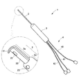
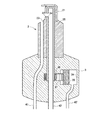
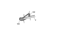
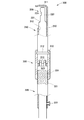
以下、本発明の実施例を図面を参照しつつ説明する。まず図1は、本発明の1実施例における手術用器具1(以下、器具)である。器具1は、緑内障手術における特に線維柱帯の切除で使用される器具であり、プローブ2、胴体部3、ケーブル・チューブ部4を備える。
Hereinafter, embodiments of the present invention will be described with reference to the drawings. First, FIG. 1 shows a surgical instrument 1 (hereinafter, an instrument) according to an embodiment of the present invention. The instrument 1 is an instrument used in glaucoma surgery in particular for excision of a trabecular meshwork, and comprises a
プローブ2は、胴体部3の先端側から延びて、患者の眼に挿入される部位である。プローブは胴体部4から直線状に形成された円筒形状を有し、1点鎖線で囲まれた拡大部分に示されているように、先端側に位置する径が小さい小径部2aと、胴体3側の大径部2bとからなる。プローブ2(小径部2a、大径部2b)の径は、線維柱帯の切除に好適な数値とすればよい。
The
プローブ2の小径部2aは、図1のとおり、内部が空洞の円筒部20の先端近傍の側面に孔部20が形成され、孔部20の逆側の側面および先端端面側に保護部21を備える。手術時にプローブ2の先端が線維柱帯に挿入される。円筒部20の内部は後述するように吸引機構と接続されていて、孔部20の内部に線維柱帯の一部が吸引される。孔部20の内部にはカッタ(切断部)が備えられており、カッタによって吸引された線維柱帯が切断されて、胴体部3の方へ吸引される。手術により汚れた洗浄液も、孔部20から胴体部3の方へ吸引される。
The
プローブ2の大径部2bは、その先端近傍の側面に孔部23を備える。孔部23は、洗浄液を供給する部位から連結しており、手術時に、孔部23からプローブ先端方向に向けて、すなわち施術位置周辺に向けて、洗浄液が流出(噴出、射出)する。プローブ2の材質は、例えば金属や剛性を有する樹脂などとすればよい。
The
胴体部3(把持部)は、手術時に施術者が把持する部位であり、例えば把持に適した筒型形状で、内部に切断部を駆動する駆動部などを備える(後述)。また切除された線維柱帯や、洗浄液、その汚れた廃液などは、胴体部3の内部を通って、プローブから(あるいはプローブへ)送られる。
The torso portion 3 (gripping portion) is a portion gripped by a practitioner at the time of surgery, and has, for example, a tubular shape suitable for gripping, and includes a driving portion for driving the cutting portion inside (described later). Also, the excised trabecular meshwork, the washing solution, the dirty waste fluid and the like are sent from the probe (or to the probe) through the inside of the
ケーブル・チューブ部4は、胴体部3の後端側から延びて、電力供給、洗浄液供給、切除部位および廃液回収に関係する。ケーブル・チューブ部4は複数のケーブルあるいはチューブを備えるとすればよく、例えば図1等のように、電力ケーブル40、洗浄液(洗浄流体)供給チューブ41、廃液チューブ42の3本(あるいは電力ケーブル40の両極線をそれぞれ数えれば4本)を備えるとすればよい。
The cable /
電力ケーブル40は、後述するようにプローブ2の先端における切除処理のための電力を供給する。洗浄液供給チューブ41は、線維柱帯の切除施術中に施術部に洗浄液を送るためのチューブである。廃液チューブ42は、切除された線維柱帯や、施術部洗浄後の汚れた廃液や手術部位からの出血などを回収して廃棄するためのチューブである。
The
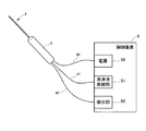
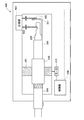
器具1は、図2に示されているように、手術時には制御装置5に接続して使用される。制御装置5は、主要な構成として、電源50(電力供給部)、洗浄液供給部51、吸引部52を備える。電源50は、器具1の電力ケーブル40が接続されることにより、器具1に電力を供給する。供給された電力により器具1は、切断部を駆動する。電源50は、商用電力を器具1に適した電力(例えば相対的に低い電圧値)に変換して、器具1に供給するとすればよい。洗浄液供給部51は、器具1の洗浄液チューブ41が接続されることにより、器具1に洗浄液を供給する。吸引部52は、器具1の廃液チューブ42が接続されることにより、器具1を通じて廃液、切除部位などを吸引する。
The instrument 1 is used in connection with the
図3から図8は、器具1の複数の実施形態における詳細な構成を示す断面図である。これらの図を参照しながら、各実施形態における器具1の構成と動作を説明する。図3から図8は概要図であり、例えば図示縦方向の長さが圧縮されている。 FIGS. 3-8 are cross-sectional views showing detailed configurations of several embodiments of the device 1. The configuration and operation of the device 1 in each embodiment will be described with reference to these figures. FIGS. 3 to 8 are schematic views, for example, in which the length in the vertical direction is compressed.
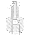
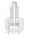
まず図3は、第1実施形態におけるプローブ2、および胴体部3の軸方向断面図を示している。同図に示されたとおり、プローブ2は図1に示された円筒部20を、外筒部(外側の円筒部)として、その内側に内筒部25(内側の円筒部)を備える。内筒部25は外筒部(円筒部20)に対して相対運動可能なように配置されている。
First, FIG. 3 shows an axial sectional view of the
内筒部25は内部が空洞とされた円筒形状であり、図3の位置関係で外筒部20の孔部22内と重なる位置に、内筒部25にも孔部24が形成されている。内筒部25の内部に形成された通路は、孔部24から廃液チューブ41まで連結する。外筒部20の図示右側と上側に渡って、保護部21が配置されている。保護部21は、例えば外筒部20の外形に沿って屈曲した板形状とすればよい。
The
図3に示すようにプローブ2は、例えば胴体部3に形成された孔部に挿入して固定された形態とすればよい。また保護部21も、例えば小径部2aと大径部2bとの境界のテーパ部に形成された孔部に挿入して固定された形態とすればよい。図3等では、円筒部20(外筒部)を大径部2bと一体で形成しているが、円筒部20(外筒部)は大径部2bとは別体として形成し、大径部2b内に挿入する形態でもよい。
As shown in FIG. 3, for example, the
小径部2aと大径部2bとの境界のテーパ部には孔部23、さらには胴体部3を通って洗浄液チューブまで貫通する、洗浄液のための通路が形成されている。洗浄液は、適切な水圧とともに制御装置5の洗浄液供給部51から供給されて、胴体部3、プローブ2を通過して孔部23から手術部位周辺へ噴出される。
In the tapered portion at the boundary between the
手術時に孔部22と孔部24とが重なった位置関係となったときに、制御装置5の吸引部52が吸引することにより孔部22、24の内部にその近傍の線維柱帯(線維柱帯全体のうちの一部)が吸引される。同時に手術部位を洗浄した洗浄液も孔部22、24内に吸引される。
When the
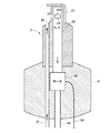
図3の実施形態においては、胴体部3内にモータ30が装備されている。モータ30は、胴体部3の中央の位置に、プローブ2の軸線と回転軸線を共有するように配置される。そしてモータ30は、電力ケーブル40を通じて制御装置5から電力が供給されて、内筒部25にプローブ2の軸線周りの回転運動をさせる。図4は、内筒部25が90度ほど回転した状態を示している。
In the embodiment of FIG. 3, a
内筒部25の孔部24の端部(例えば図示左右方向の端部)にはカッタ24aが形成され、内筒部25が外筒部20に対して回転することにより、上述のとおり孔部22、24内に吸引された線維柱帯がカッタ24aによって切断される。外筒部20の孔部22にもカッタを形成してもよい。切断された線維柱帯と廃液は、内筒部25内の通路を通って、さらに廃液チューブを通って吸引部52まで吸引される。吸引部52に貯留された線維柱帯や廃液は、例えば適切な方法で廃棄すればよい。
A
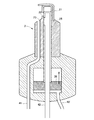
次に図5は、器具1の別の実施形態を示している。図5から図8の実施形態では、図3、図4と同符号で示された部位は同じ部位であり、重複する説明は省略する。 Referring now to FIG. 5, another embodiment of the device 1 is shown. In the embodiments of FIGS. 5 to 8, the parts denoted by the same reference numerals as those in FIGS. 3 and 4 are the same parts, and redundant descriptions will be omitted.
図5の実施形態では、モータ30の替わりにエアシリンダの機構が装備されている。そして制御装置5’は電力供給部50の替わりにポンプ53を装備する。また器具1は、電力ケーブル40の替わりに、動力としての空気を供給するエアチューブ40’を装備する。器具1は、胴体部3内にシリンダ31が形成され、ピストン32、ねじ部33を備える。
In the embodiment of FIG. 5, an air cylinder mechanism is provided instead of the
シリンダ31はプローブ2と軸線を共有する円筒形状で形成され、シリンダ31内に図示上下方向に移動可能なようにピストン32が配置される。ピストン32には、ねじ溝が形成され、ねじ部33のねじ溝とねじ嵌合している。ねじ部33は内筒部25に固定されている。
The
以上の構成で、制御装置5’のポンプ53から動力として空気の供給および吸引が繰り返されると、ピストン32が上下運動し、その上下運動がピストン32とねじ部33間のねじ機構によって、ねじ部33の回転運動に変換される。ねじ部33が回転運動することにより、内筒部25が回転する。これにより内筒部25の孔部24のカッタ24aが、孔部24内に吸引された線維柱帯を切断する。
With the above configuration, when supply and suction of air are repeated as motive power from the pump 53 of the control device 5 ', the
次に図6は器具1の第3の実施形態を示す。この実施形態もエアシリンダ構造を備える。具体的には、器具1は胴体部3内に、シリンダ34が形成され、ピストン35、ギア36、ラック37を備える。シリンダ34はその軸方向が、プローブ2の軸方向と直交な円筒形状として形成され、ピストン35が図示左右方向に移動可能なようにシリンダ34内に配置される。ラック37はピストン35に固定されて、ピストン37と一体に左右に運動する。ギア36は、ラック37との間でカム機構を形成し、ラック37の並進運動を回転運動に変換する。ギア36は内筒部25に固定されている。
Next, FIG. 6 shows a third embodiment of the device 1. This embodiment also has an air cylinder structure. Specifically, the device 1 has a
以上の構成で、器具1は、制御装置5’のポンプ53から動力として空気の供給および吸引が繰り返されると、ピストン32が図示左右運動し、それと一体にラック37も左右運動し、その左右運動がラック37とギア36間のカム機構によって、ギア36の回転運動に変換される。ギア36が回転運動することにより、内筒部25も回転する。これにより内筒部25の孔部24のカッタ24aが、孔部24内に吸引された線維柱帯を切断する。
With the above configuration, when the supply and suction of air as power from the pump 53 of the
なお図3、図4における内筒部25の回転運動は同一方向への一定速度の回転運動であり、図5、図6における内筒部25の回転運動では、正逆方向への所定回転角度幅の回転を繰り返すとすればよい。
The rotational movement of the inner
次に、図7、図8は、器具1の第4の実施形態である。この実施形態では、内筒部25が図示上下方向へ平行移動する。具体的に器具1は、シリンダ31が形成され、ピストン38を備える。シリンダ31はプローブ2と軸線を共有する円筒形状で形成され、シリンダ31内に図示上下方向に移動可能なようにピストン38が配置される。ピストン38は内筒部25に固定されている。
Next, FIGS. 7 and 8 show a fourth embodiment of the device 1. In this embodiment, the inner
以上の構成で、制御装置5’のポンプ53から動力として空気の供給および吸引が繰り返されると、ピストン38が図示上下運動する。ピストン38が上下運動することにより、内筒部25も上下運動する。図8には内筒部25が図示下方に移動した状態が示されている。内筒部25が下方へ移動することにより、内筒部25の孔部24のカッタ24aが、孔部24内に吸引された線維柱帯を切断する。
With the above configuration, when supply and suction of air are repeated as motive power from the pump 53 of the
この実施形態では、内筒部25の孔部24における上側の端部にカッタ24aを形成すればよい。あるいは内筒部25の移動距離を長くして、内筒部25の孔部24における上下両側の端部にカッタ24aを形成して、上下両方のカッタ24aで線維柱帯を切断するようにすることも好適である。もちろん外筒部25の孔部22にもカッタを備えてよい。
In this embodiment, the
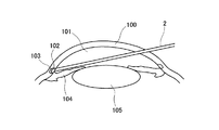
以上の構成を備えた器具1を緑内障の外科的処置における線維柱帯の切除において使用する。図9に示された眼の構造の概要図を参照しつつ説明すると、眼の虹彩104の図示下部に位置する毛様体において房水は生成される。通常、この房水は、水晶体105に押し寄せた後に、前眼房101の周方向にある隅角から流れ出る。隅角には線維柱帯102やシュレム管103が存在する。線維柱帯102は房水の流出を制限するフィルタの役目を果たす。シュレム管103は房水が流れ出るための構造を有する。
The instrument 1 with the above configuration is used in the resection of trabecular meshwork in the surgical treatment of glaucoma. Referring to the schematic view of the structure of the eye shown in FIG. 9, aqueous humor is generated in the ciliary body located below the
線維柱帯102が異常に変形したり機能異常を起こした場合、前眼房101を出る房水の流れが制限される。それにより眼圧が異常に増加し、緑内障となる。本発明による手術用器具1は、この緑内障に対する外科的処置において効果的な器具である。器具1を用いた手術方法の一例は以下のとおりである。
If the
手術の準備として、線維柱帯が隅角鏡を通して正面から見えるように、顕微鏡を術者側に30から45度傾けると同時に患者の頭位も決める。角膜をナイフ(例えば1.7mm)で切開し、房水を少し抜いた後、粘弾性物質を注入する。見やすくするために、特に隅角部分に充満させるとよい。隅角鏡を置いて線維柱帯を確認したらプローブ2をシュレム管103に挿入し、切除を開始する。図10に示されたとおり、シュレム管103内において、孔部21が形成された側へ向かって器具1を動かす。このとき、器具1が前進する方向は、保護部21が延設された方向と同じとなる。
In preparation for surgery, the microscope should be tilted 30 to 45 degrees toward the practitioner so that the patient's head is positioned as well, so that the trabecular meshwork can be viewed from the front through the angle mirror. The cornea is incised with a knife (eg, 1.7 mm), and after a little aqueous humor is withdrawn, the visco-elastic material is injected. In order to make it easy to see, it is particularly preferable to fill the corners. After placing the corner mirror and confirming the trabecular meshwork, the
時計回り、その後反時計周りに切除を進めると、90から120度まで切除できる。(白内障手術を同時に行う場合には、ここで1.7mmの角膜切開創を3.0mmまで広げ、レンズを入れる。)最後に粘弾性物質と逆流性出血を洗って完全に除去したら、創口部から房水が漏れてこないことを確認する。ある程度眼圧が保たれるように、必要ならば1針(例えば10−0ナイロン)ほど傷口を縫合する。 If you proceed with ablation clockwise and then counterclockwise, you can excise from 90 to 120 degrees. (If performing cataract surgery at the same time, expand the 1.7 mm corneal incision to 3.0 mm and insert the lens.) Finally, wash away the viscoelastic substance and regurgitation bleeding completely to remove the wound Make sure that the fluid does not leak from the If necessary, suture the wound with a needle (eg, 10-0 nylon) so as to maintain a certain degree of intraocular pressure.
この手術の利点としては例えば、角膜100の切開創が小さく、シュレム管が損傷しにくいという低侵襲性と、線維柱帯を実際に見ながら切れる確実性等があげられる。また術後の重篤な合併症が少ないので、早期、中期で21mmHg以上の高眼圧の緑内障であれば、点眼を増やすよりも早期の手術適応の可能性がある。
The advantages of this operation include, for example, the low invasiveness that the incisional wound of the
以上のとおり、本発明の器具1を用いて、繊維柱帯が切除(掻爬)される(なお線維柱帯切除との表現には、前房側からシュレム管内壁を所定角度範囲で切除し、線維柱帯を露出させること等も含まれるとする)。この際、シュレム管外壁は保護部21により保護される。
As described above, the trabecular meshwork is excised (scratched) using the device 1 of the present invention (note that, in the expression of trabeculectomy, the inner wall of Schlemm's canal is excised from the anterior chamber side within a predetermined angle range, Exposing the trabecular meshwork etc. shall be included. At this time, the outer wall of Schlemm's canal is protected by the
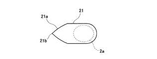
なお保護部21は多様な形状が可能である。図11から図13には、保護部21の1実施形態が示されている。図11は斜視図、図12は図11を図示上方から見た図、図13は図11を孔部22の側から見た図である。上述のとおりプローブ2の小径部2aにおける孔部22が形成された側面と逆側の側面に当接するように保護部21は配置され、プローブ2の先端形状に沿って屈曲して、プローブ2の先端面にほぼ平行方向に延設されている。
In addition, the
図12に示すとおり、保護部21の前部21aは、三角形状(あるいは先細り形状)とすればよい(ただし角部は曲面形状とすればよい)。この形状は、図10に示すようにプローブ2をシュレム管103に沿って進行させるときに、進行方向に向かって保護部21の先が細くなっているので、プローブ2の進行が円滑に行える。このように保護部21は、プローブの先端をシュレム管に沿って進行させるガイド部の役割も果たす。
As shown in FIG. 12, the
また図12に示すとおり、保護部21の先端21bは尖った形状としてもよい。この形状は、図16に示すように手術の最初にプローブの先端を線維柱帯の中に進入させるときに、保護部21の先端21bを線維柱帯に突き刺してプローブを進入させるのに好適である。
Further, as shown in FIG. 12, the
また図13(A)に示すように、保護部21の図示上端は丸く凹形状を持たせればよい。これにより手術時にシュレム管の曲面形状に沿い、シュレム管を傷つけないので好適である。保護部21の上端の形状は、山型の凹形状でもよい。あるいは図13(B)に示すとおり、保護部の図示上端は平坦な形状としてもよい。本発明では図13の例に限定されず、保護部21の図示上端の形状は、非切除部を保護する役割、ガイド部としての役割を果たす形状にすればよい。
Further, as shown in FIG. 13A, the upper end of the
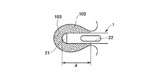
プローブの先端の形状においては、保護部21(の上端)から孔部22までの距離を適切にすることが重要である。図15に示すとおり、保護部21(の上端)から孔部22までの距離dは、保護部21が線維柱帯に進入してからシュレム管に当接するまでの範囲内にある状態で、孔部22が切除すべき線維柱帯の位置に来るように設定する。ここで、切除すべき線維柱帯の位置とは、例えばシュレム管内の線維柱帯のうちで眼の中心に近い側(シュレム管にプローブを挿入する側)を含むとすればよい。
In the shape of the tip of the probe, it is important to make the distance from (the upper end of) the
本発明の緑内障の手術用器具1は、既存の医療装置との並存が可能である。そのしくみが図14に示されている。 The glaucoma surgical instrument 1 of the present invention can coexist with existing medical devices. The mechanism is shown in FIG.
図14には、硝子体切除用の手術システムが示されている。同システムは、硝子体切除用制御装置500と硝子体切除用器具100を備える。硝子体切除用制御装置500は、硝子体切除用の電力供給部50(あるいはポンプ53)、洗浄液供給部51、吸引部52を備える。硝子体切除用器具100は、ケーブルあるいはチューブを備えて、それらを電力供給部50(あるいはポンプ53)、洗浄液供給部51、吸引部52に接続することにより、硝子体切除用器具100の切除部に患部(硝子体)切除のためにカッターを駆動する電力が供給され、手術部位へ洗浄液が供給され、切除された部位(硝子体)や、手術部位から還流された廃液が吸引、回収される。これにより硝子体切除用器具100を用いた硝子体切除手術が可能となる。
A surgical system for vitrectomy is shown in FIG. The system comprises a vitrectomy controller 500 and a
発明者の知見によれば、線維柱帯切除用の制御装置5(5’)に要求される機能は、既存の硝子体切除用制御装置500との機能と近く、両装置の兼用が十分可能である。すなわち、本発明の器具1に対する上述の制御装置5(5’)は、図14の硝子体切除用制御装置500で兼用(代行)することができる。これにより、従来は別々に構築されていた硝子体切除用のシステムと線維柱帯切除用のシステムとの装置部分を兼用して、眼科医療におけるシステムの簡素化、省スペース化、低コスト化に大きく寄与できる。なお硝子体切除用制御装置500に限らず、他の同様な機能を有する装置でもよい。 According to the inventor's knowledge, the function required of the control device 5 (5 ') for trabecular meshwork is close to the function of the existing vitrectomy control device 500, and both devices can be used sufficiently. It is. That is, the control device 5 (5 ') described above for the device 1 of the present invention can be shared (alternate) with the vitrectomy control device 500 of FIG. As a result, the device part of the system for vitrectomy and the system for trabeculectomy, which were conventionally built separately, are combined to simplify, save space, and reduce the cost of the system in ophthalmic medicine. It can contribute greatly. In addition, not only the control device 500 for vitrectomy but a device having another similar function may be used.
上記実施例は特許請求の範囲に記載された趣旨の範囲内で任意に変更してよい。例えば器具1は、硝子体の切除手術に用いてもよい。器具1は、硝子体切除に必要な装備を有するので、緑内障と硝子体の両方に対応できる高い汎用性を実現できる。 The above embodiments may be arbitrarily modified within the scope of the claims. For example, the device 1 may be used for vitrectomy. Since the instrument 1 has the necessary equipment for vitrectomy, it can realize high versatility that can cope with both glaucoma and vitreous.
以上述べてきた実施形態は、図1に示すとおり保護部21と、それ以外のプローブ2、胴体部3、ケーブル・チューブ部4とが一体となった形態であったが、本発明はこうした形態に限定されない。図17には、保護部のみを取り付ける形態の取り付け型器具の斜視図が示されている。これを取り付ける対象は、例えば図14に示した硝子体手術用器具200とすればよい。以下では器具200に取り付けた場合を説明する。
In the embodiment described above, as shown in FIG. 1, the
なお器具200は、保護部が形成されていない以外は器具1と同様の構造、形状を有するとする。図18に示すとおり、器具200のプローブは、小径部220と大径部230とを有し、小径部220に孔部221が形成され、大径部230から小径部220へのテーパ部に孔部231が形成されている。孔部231からは施術部へ洗浄液を供給する。孔部221はカッタを装備して、線維柱帯(あるいは硝子体)を吸入して、カッタで切断し、廃液とともに制御装置へ送る。
Note that the
図17に示された取り付けタイプの手術用器具300(以下、器具)は、先端側円筒部310(取り付け部)、胴体側円筒部320(取り付け部)、接続部330(調節部)からなる。先端側円筒部310に保護部311が形成され、先端側円筒部310、胴体側円筒部320、接続部330の順で、器具200のプローブの先端側から配置される。先端側円筒部310、胴体側円筒部320、接続部330には、軸方向中央部に器具200のプローブが挿入される貫通孔312が形成されている。
The attachment type surgical instrument 300 (hereinafter, instrument) shown in FIG. 17 includes a distal end side cylindrical portion 310 (attachment portion), a body side cylindrical portion 320 (attachment portion), and a connection portion 330 (adjustment portion). The
図18は、器具300が器具200に取り付けられた、すなわち器具200が貫通孔312に挿入された状態での一部断面図である。器具300は、器具200に取り付けるための構造とともに、保護部311の位置決めのための構造を備える。以下で、それらを説明する。
FIG. 18 is a partial cross-sectional view in which the
先端側円筒部310には、鍔部312、嵌合部313が形成されている。鍔部312は、先端側円筒部310の外周面において周方向外方に突出する形状で形成されている。嵌合部313は、先端側円筒部310の図示下端つまり胴体側の端部において、軸方向に向かう凹形状と凸形状とが周方向に沿って繰り返すように形成されている。
A
接続部330には、凹部332、ねじ溝部331が形成されている。凹部332は、接続部330の内周面に周方向に沿って形成された凹形状であって、先端側円筒部310の鍔部312と嵌合する。これにより先端側円筒部310と接続部330とは周方向に摺動可能となる。ねじ溝部331は、接続部330の内周面の凹部332より図示下部に形成されたねじ溝である。
In the
胴体側円筒部320は、ねじ溝部321、嵌合部323、ボルト322を備える。ねじ溝部321は、胴体側円筒部320の外周面に形成されたねじ溝であり、接続部330のねじ溝部331と螺合する。これにより、接続部330を軸周りに回動させることによって、接続部330と胴体側円筒部320とは図示上下方向に相対移動する。
The body side
嵌合部323は、胴体側円筒部320の図示上端側において、軸方向に向かう凹形状と凸形状とが周方向に沿って繰り返すように形成されて、先端側円筒部310の嵌合部313と嵌合する。これにより胴体側円筒部320と先端側円筒部310とは、嵌合部313、323が嵌合しつつ図示上下方向に相対移動が可能となる。
The
ボルト322は、胴体側円筒部320の側面に形成された貫通孔に螺合されている。器具300に器具200が挿入されて適切な位置となった状態でボルト322を締め付けることによって、胴体側円筒部320が器具200に対して固定(位置決め)される。なおボルト322を備えず、胴体側円筒部320が適切な圧力で圧入されることによる固定でもよい。
The
ボルト322によって胴体側円筒部320が器具200固定された状態で、接続部330を軸周りに右回りに回動させると、胴体側円筒部320は固定されているので、接続部330が回動しながら図示上方へと移動する。鍔部312と凹部332とが嵌合しているので、接続部330の上方への移動につれて、先端側円筒部310も図示上方に移動する。先端側円筒部310の上方への移動の際、嵌合部313、323の嵌合によって、先端側円筒部310軸周りの回動は規制(禁止)される。したがって先端側円筒部310は回動せずに、図示上方に平行移動する。当然、接続部330を逆方向に回動させると、先端側円筒部310は図示下方に平行移動する。
When the connecting
以上のとおり、器具300に器具200のプローブを挿入して、ボルト322で胴体側円筒部320を器具200へ固定し、その状態で接続部330を回動させることによって、先端側円筒部310が図示上下方向に平行移動する。これにより、接続部330の回動角度を調節することによって、保護部311の適切な位置決めが行える。つまり、保護部311(の上端)から孔部221までの距離(図15のd)が適切に調節できる。このような取り付けタイプの器具300は既存の眼科手術用器具(例えば硝子体手術用器具や緑内障用の器具に限定されず、他の眼科手術用器具でもよい)に取り付けて使用できるので、顕著なコスト削減の効果を奏する。
As described above, the probe of the
接続部330を回動して、保護部311(の上端)から孔部221までの距離を適切に調節する処理は、施術者(作業者)が手作業で行ってもよいが、微細な位置決めであるので、機械によっておこなってもよい。この目的のための装置の例が図19に示されている。
The process of rotating the
図19の装置400は、筐体のなかに(器具200が挿入されてボルト322で固定された)器具300を配置(把持)して、保護部311を精密に位置決めするための装置である。装置400は、主要な構造として、把持部401、挟持部402、403、モータ410、計測部420、制御部430を備える。
The
把持部401は、接続部330を径方向外方から把持する部位である。把持部401は、周方向に間隔を置いて、あるいは全周に渡って配置されているとすればよい。挟持部402、403は、棒状の部位であり、図示左右方向に移動可能で、図19に示されるように、保護部311の上端(図示右端)と孔部221の上端(図示右端)とを(適切な圧力で)挟持する。
The
モータ410は、例えばステップモータなどとして、把持部401が軸周りの指令された角度だけ回動するように駆動する。計測部420、挟持部402、403のそれぞれの先端間の距離を計測する。計測方法は周知の電子計測の手法を用いればよい。
The
制御部430は、通常のコンピュータと同様の構造、すなわち各種計算などの情報処理のためのCPU、CPUの作業領域としての一時記憶部のRAM、プログラムなど必要な各種情報を記憶するROM等を備える。制御部430は、計測部420の計測結果をモニターしながら、保護部311(の上端)から孔部221までの距離が、線維柱帯切除手術で最適な距離となるための回動角度をモータ410に指令する。
The
制御部430によるこの制御は、例えばフィードバック制御とすればよい。すなわち、計測部420での計測値をフィードバックして目標値(目標距離)との差分を算出し、この算出結果を適切に設計されたコントローラに入力して、その出力をモータ410への入力値とすればよい。こうした制御によって、保護部311(の上端)から孔部221までの距離を最適な距離に調節できる。
This control by the
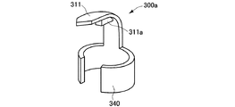
本発明の手術用器具の取り付けタイプの形態は以上の例に限定されない。図20から図21に別の実施形態が示されている。図20は、取り付けタイプの手術用器具の第2の例の斜視図、図21は、取り付けタイプの手術用器具の第3の例の斜視図、図22は、図20又は図21を側方から見た図である。図20から図22の例は、図17等の例よりも簡素な形態であり、既存の器具(例えば器具200の場合で説明する)の先端のみに取り付ける形態である。 The form of the attachment type of the surgical instrument of the present invention is not limited to the above examples. Another embodiment is shown in FIGS. 20-21. FIG. 20 is a perspective view of a second example of the attachment type surgical instrument, FIG. 21 is a perspective view of the third example of the attachment type surgical instrument, and FIG. 22 is a side view of FIG. It is the figure seen from. The example of FIGS. 20-22 is a form simpler than the example of FIG. 17 grade | etc., And is a form attached only to the front-end | tip of the existing instrument (for example, it demonstrates by the case of the instrument 200).
図20に示された器具300aは、左右両側に湾曲して延設された湾曲部340の図示上方に保護部311を有する。保護部311は、上述の保護部21と同様の形状とすればよい。器具300aは、器具200のプローブが湾曲部340内に挿入されるようにして、例えば器具200の先端側から装着する。
The
器具300aの器具200への固定は、例えば器具200のプローブが湾曲部340に圧入されることによってもよい。あるいは、器具200のプローブを湾曲部340内に挿入した後に、湾曲部340をペンチなどの器具で外側から加締める(押圧して変形する)ことによって器具200に固定する形態でもよい。あるいは湾曲部340の内側に接着材(粘着材)層を形成して、接着(粘着)によって器具200に固定してもよい。
Fixation of the
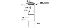
図21に示された器具300bは、円筒形状の円筒部341の図示上方に保護部311が形成されている。器具300bは、器具200のプローブが円筒部341内に挿入されるようにして、例えば器具200の先端側から装着する。
In the
器具300bの器具200への固定は、例えば器具200のプローブが円筒部341に圧入されることによってもよい。あるいは、器具200のプローブを円筒部341内に挿入した後に、円筒部341をペンチなどの器具で外側から加締める(押圧して変形する)ことによって器具200に固定する形態でもよい。あるいは円筒部341の内側に接着材(粘着材)層を形成して、接着(粘着)によって器具200に固定してもよい。
The fixing of the
器具300a、300bにおいても、上述のように図15で示したような保護部311の上端から吸入口22までの距離dを適切にする必要がある。この目的のために、器具300a、300bには、図20、図21に示されているように、保護部311の図示下側に例えば板形状の長さ調節部311aが形成されている。
Also in the
長さ調節部311aの形成によって、図22に示されているように、器具200の先端が長さ調節部311aに当接するように器具300a、300bが器具200に固定すれば、保護部311の上端から吸入口22までの距離dが、上述の意味で緑内障手術の線維柱帯切除に適切な長さになるようにする。長さ調節部311aの厚さは、この要求を満たすように、既存の器具200の寸法に適して設定しておく。以上のような簡易な形態の器具300a、300bを、既存の器具(器具200に限定されない)に装着することによって低コストで緑内障手術用の器具が作成できる。
If the
1 手術用器具
2 プローブ
3 胴体部(把持部)
4 ケーブル・チューブ部
40 電力ケーブル(第1送出部)
40’ エアチューブ(第1送出部)
41 洗浄液チューブ(第2送出部)
42 廃液チューブ(第3送出部)
1
4 Cable /
40 'Air tube (1st delivery part)
41 Cleaning solution tube (2nd delivery part)
42 Waste tube (3rd delivery part)
Claims (3)
施術者が把持する把持部と、
その把持部の端部から棒状に延びるように配置された剛性を有するプローブと、
を備え、前記プローブは、
切除部位である線維柱帯に向けて洗浄液を流出する流出口と、
前記プローブの側面に形成されて、前記流出口から流出した洗浄液を廃液として回収するとともに、線維柱帯をプローブ内部へ吸引する吸引口と、
その吸引口へ吸引された線維柱帯を切断する切断部と、
前記吸引口および切断部よりも前記プローブの先端側に配置されて、前記プローブの先端において前記吸入口が形成された側面の側に延設された形状を有し、前記切断部による線維柱帯切除中に、前記切断部とシュレム管外壁との間に位置することで、非切除部位であるシュレム管外壁を切除および吸引から保護する保護部と、を備え、
硝子体切除手術における動力の伝達と洗浄液の送出と廃液の回収とを行う硝子体切除用装置における硝子体切除用の動力供給部に接続されて、その装置から前記切断部に切断のための動力を送るための第1送出部と、
前記硝子体切除用装置における硝子体切除用の洗浄液供給部に接続されて、その硝子体切除用装置から前記流出口に洗浄液を送るための第2送出部と、
前記硝子体切除用装置における硝子体切除用の吸引部に接続されて、その硝子体切除用装置へ前記吸引口で吸引された廃液および切断された線維柱帯を送るための第3送出部と、
を備えたことを特徴とする手術用器具。 A surgical instrument used in trabeculectomy,
A grasping portion grasped by a practitioner;
A rigid probe disposed so as to extend in a rod shape from an end of the grip;
And the probe comprises
An outlet for discharging the washing solution to the trabecular meshwork, which is a site of resection;
A suction port formed on the side of the probe to collect as a waste liquid the washing solution flowing out from the outlet, and suction the trabecular meshwork into the probe;
A cutting portion for cutting the trabecular meshwork sucked into the suction port;
It is disposed on the tip side of the probe with respect to the suction port and the cutting portion, and has a shape extending on the side of the tip of the probe where the suction port is formed, and the trabecular meshwork by the cutting portion And a protection unit located between the cutting portion and the outer wall of Schlemm's canal during resection to protect the outer wall of Schlemm's canal, which is a non-resected site, from the removal and suction.
It is connected to the power supply unit for vitrectomy in the vitrectomy device for transmitting the power in the vitrectomy operation, delivering the washing solution, and collecting the waste liquid, and the power for cutting from the device to the cutting unit A first sending unit for sending
Wherein connected to the cleaning liquid supply unit for vitrectomy in vitrectomy equipment, and a second sending unit for sending a cleaning liquid to the outlet from the vitrectomy equipment,
It is connected to a suction unit for vitrectomy in the vitrectomy equipment, a third transmission section for sending the sucked waste and cut the trabecular meshwork at the suction port to the vitrectomy equipment ,
A surgical instrument characterized by comprising.
前記切断部は、その内筒部の側面に形成されて、プローブに対する内筒部の相対的な回転運動または並進運動によって切除部位を切断する切断刃を備えた請求項1に記載の手術用器具。 An inner tubular portion disposed so as to share a longitudinal axis inside the probe,
The surgical instrument according to claim 1 , wherein the cutting portion is formed on the side surface of the inner cylindrical portion, and is provided with a cutting blade which cuts the excision site by relative rotational movement or translational movement of the inner cylindrical portion with respect to the probe. .
切除部位である線維柱帯に向けて洗浄液を流出する流出口と、前記プローブの側面に形成されて、前記流出口から流出した洗浄液を廃液として回収するとともに、線維柱帯をプローブ内部へ吸引する吸引口と、その吸引口へ吸引された線維柱帯を切断する切断部と、を備えた剛性を有するプローブに、前記手術用器具を取り付けるための取り付け部と、
前記吸引口および切断部よりも前記プローブの先端側に配置されて、前記プローブの先端において前記吸引口が形成された側面の側に延設された形状を有し、前記切断部による線維柱帯切除中に、前記切断部とシュレム管外壁との間に位置することで、非切除部位であるシュレム管外壁を切除および吸引から保護する保護部と、
前記取り付け部によって前記プローブに取り付けられた状態で、前記保護部と前記吸引口との間の距離を調節する調節部と、
を備えたことを特徴とする手術用器具。 A surgical instrument used in trabeculectomy ,
It is formed on the side of the probe and an outlet for discharging the washing solution to the trabecular meshwork which is the excision site , and the washing solution flowing out from the outlet is collected as a waste liquid and the trabecular meshwork is sucked into the probe. A mounting portion for mounting the surgical instrument on a rigid probe having a suction port and a cutting portion for cutting a trabecular mesh drawn into the suction port;
It is disposed on the tip side of the probe with respect to the suction port and the cutting portion, and has a shape extending on the side of the tip of the probe where the suction port is formed, and the trabecular meshwork by the cutting portion A protection portion located between the cutting portion and the outer wall of Schlemm's canal during excision to protect the outer wall of Schlemm's canal, which is a non-resected site , from ablation and suction;
An adjustment unit for adjusting a distance between the protection unit and the suction port in a state of being attached to the probe by the attachment unit;
A surgical instrument characterized by comprising.
Priority Applications (8)
| Application Number | Priority Date | Filing Date | Title |
|---|---|---|---|
| JP2011193780A JP5000000B1 (en) | 2011-09-06 | 2011-09-06 | Surgical instruments |
| KR1020147004141A KR101626103B1 (en) | 2011-09-06 | 2012-08-13 | Surgical instrument |
| PCT/JP2012/070599 WO2013035497A1 (en) | 2011-09-06 | 2012-08-13 | Surgical instrument |
| US14/238,117 US20140194916A1 (en) | 2011-09-06 | 2012-08-13 | Surgical instrument |
| CN201280042708.2A CN103781445B (en) | 2011-09-06 | 2012-08-13 | Operation utensil |
| EP12830334.4A EP2754427B1 (en) | 2011-09-06 | 2012-08-13 | Surgical instrument |
| IL230888A IL230888A0 (en) | 2011-09-06 | 2014-02-09 | Surgical instrument |
| US15/654,276 US10463385B2 (en) | 2011-09-06 | 2017-07-19 | Surgical instrument |
Applications Claiming Priority (1)
| Application Number | Priority Date | Filing Date | Title |
|---|---|---|---|
| JP2011193780A JP5000000B1 (en) | 2011-09-06 | 2011-09-06 | Surgical instruments |
Publications (2)
| Publication Number | Publication Date |
|---|---|
| JP5000000B1 true JP5000000B1 (en) | 2012-08-15 |
| JP2013052168A JP2013052168A (en) | 2013-03-21 |
Family
ID=46793948
Family Applications (1)
| Application Number | Title | Priority Date | Filing Date |
|---|---|---|---|
| JP2011193780A Active JP5000000B1 (en) | 2011-09-06 | 2011-09-06 | Surgical instruments |
Country Status (7)
| Country | Link |
|---|---|
| US (2) | US20140194916A1 (en) |
| EP (1) | EP2754427B1 (en) |
| JP (1) | JP5000000B1 (en) |
| KR (1) | KR101626103B1 (en) |
| CN (1) | CN103781445B (en) |
| IL (1) | IL230888A0 (en) |
| WO (1) | WO2013035497A1 (en) |
Cited By (1)
| Publication number | Priority date | Publication date | Assignee | Title |
|---|---|---|---|---|
| EP3875066A1 (en) | 2020-03-05 | 2021-09-08 | Chukyo Medical Co., Inc. | Ophthalmic surgery instrument |
Families Citing this family (17)
| Publication number | Priority date | Publication date | Assignee | Title |
|---|---|---|---|---|
| US7909789B2 (en) | 2006-06-26 | 2011-03-22 | Sight Sciences, Inc. | Intraocular implants and methods and kits therefor |
| EP2531138B1 (en) | 2010-02-05 | 2016-11-30 | Sight Sciences, Inc. | Intraocular implants and related kits and methods |
| ES2961369T3 (en) | 2012-03-20 | 2024-03-11 | Sight Sciences Inc | Eye delivery systems |
| JP5458205B1 (en) * | 2013-06-28 | 2014-04-02 | 株式会社中京メディカル | Surgical instruments |
| US10299958B2 (en) | 2015-03-31 | 2019-05-28 | Sight Sciences, Inc. | Ocular delivery systems and methods |
| DE102015208646A1 (en) * | 2015-05-08 | 2016-11-10 | Frank Zastrow | Surgical hand-held device and a protective device |
| JP6770291B2 (en) * | 2015-09-01 | 2020-10-14 | マニー株式会社 | Vitrectomy probe |
| CN105662700A (en) * | 2016-01-07 | 2016-06-15 | 佛山市禾才科技服务有限公司 | Ophthalmic scalpel with double liquid flow tubes |
| US10555834B2 (en) * | 2016-07-11 | 2020-02-11 | Novartis Ag | Vitrectomy probe with rotary cutter and associated devices, systems, and methods |
| US20210128353A1 (en) * | 2016-12-27 | 2021-05-06 | Rohto Pharmaceutical Co., Ltd. | Surgical Tool |
| CN107174399B (en) * | 2017-05-27 | 2019-07-12 | 天津优视眼科技术有限公司 | What a kind of interior road was implemented applies Lai Mushi pipe operation transportation system |
| EP3755288A4 (en) * | 2018-02-19 | 2021-12-08 | Singapore Health Services Pte Ltd | Method and apparatus for shearing tissue at a target surgical site |
| US20220047281A1 (en) * | 2018-09-28 | 2022-02-17 | Flow Medical Corporation | Catheter Apparatus |
| GB2581316B (en) * | 2018-11-08 | 2023-08-09 | Nachum Zvi | Device for removing liquid from an eye of a subject |
| US11504270B1 (en) | 2019-09-27 | 2022-11-22 | Sight Sciences, Inc. | Ocular delivery systems and methods |
| CN115590677A (en) * | 2022-10-20 | 2023-01-13 | 微创视神医疗科技(上海)有限公司(Cn) | Trabecular meshwork cutting device |
| JP7411297B1 (en) | 2023-08-28 | 2024-01-11 | 株式会社トラベクター | Ophthalmic surgical instruments, intraocular excision components, and manufacturing methods thereof |
Citations (2)
| Publication number | Priority date | Publication date | Assignee | Title |
|---|---|---|---|---|
| JP2005185427A (en) * | 2003-12-25 | 2005-07-14 | Takashima Sangyo Kk | Vitreous body cutter, vitreous body surgery apparatus with vitreous body cutter, and vitreous body cutter production method |
| JP2010099208A (en) * | 2008-10-22 | 2010-05-06 | Nidek Co Ltd | Irrigation and suction apparatus |
Family Cites Families (7)
| Publication number | Priority date | Publication date | Assignee | Title |
|---|---|---|---|---|
| US4759363A (en) * | 1985-09-17 | 1988-07-26 | Jensen Ronald P | Scalpel with removable depth guard |
| US5106364A (en) * | 1989-07-07 | 1992-04-21 | Kabushiki Kaisha Topcon | Surgical cutter |
| US5643297A (en) * | 1992-11-09 | 1997-07-01 | Endovascular Instruments, Inc. | Intra-artery obstruction clearing apparatus and methods |
| US6514268B2 (en) * | 1999-08-30 | 2003-02-04 | Alcon Universal Ltd. | Method of operating microsurgical instruments |
| CA2528060C (en) * | 2003-06-10 | 2012-12-11 | Neomedix Corporation | Device and methods useable for treatment of glaucoma and other surgical procedures |
| CA2680839A1 (en) | 2007-03-20 | 2008-09-25 | Alcon, Inc. | Surgical laser system control architecture |
| US20090287233A1 (en) * | 2008-05-15 | 2009-11-19 | Huculak John C | Small Gauge Mechanical Tissue Cutter/Aspirator Probe For Glaucoma Surgery |
-
2011
- 2011-09-06 JP JP2011193780A patent/JP5000000B1/en active Active
-
2012
- 2012-08-13 CN CN201280042708.2A patent/CN103781445B/en active Active
- 2012-08-13 KR KR1020147004141A patent/KR101626103B1/en active IP Right Grant
- 2012-08-13 US US14/238,117 patent/US20140194916A1/en not_active Abandoned
- 2012-08-13 WO PCT/JP2012/070599 patent/WO2013035497A1/en active Application Filing
- 2012-08-13 EP EP12830334.4A patent/EP2754427B1/en active Active
-
2014
- 2014-02-09 IL IL230888A patent/IL230888A0/en unknown
-
2017
- 2017-07-19 US US15/654,276 patent/US10463385B2/en active Active
Patent Citations (2)
| Publication number | Priority date | Publication date | Assignee | Title |
|---|---|---|---|---|
| JP2005185427A (en) * | 2003-12-25 | 2005-07-14 | Takashima Sangyo Kk | Vitreous body cutter, vitreous body surgery apparatus with vitreous body cutter, and vitreous body cutter production method |
| JP2010099208A (en) * | 2008-10-22 | 2010-05-06 | Nidek Co Ltd | Irrigation and suction apparatus |
Cited By (2)
| Publication number | Priority date | Publication date | Assignee | Title |
|---|---|---|---|---|
| EP3875066A1 (en) | 2020-03-05 | 2021-09-08 | Chukyo Medical Co., Inc. | Ophthalmic surgery instrument |
| US11806281B2 (en) | 2020-03-05 | 2023-11-07 | Chukyo Medical Co., Inc. | Ophthalmic surgery instrument |
Also Published As
| Publication number | Publication date |
|---|---|
| CN103781445B (en) | 2015-11-25 |
| US10463385B2 (en) | 2019-11-05 |
| EP2754427A1 (en) | 2014-07-16 |
| JP2013052168A (en) | 2013-03-21 |
| US20140194916A1 (en) | 2014-07-10 |
| IL230888A0 (en) | 2014-03-31 |
| WO2013035497A1 (en) | 2013-03-14 |
| EP2754427B1 (en) | 2019-04-03 |
| KR101626103B1 (en) | 2016-05-31 |
| KR20140057274A (en) | 2014-05-12 |
| US20170311970A1 (en) | 2017-11-02 |
| CN103781445A (en) | 2014-05-07 |
| EP2754427A4 (en) | 2015-04-22 |
Similar Documents
| Publication | Publication Date | Title |
|---|---|---|
| JP5000000B1 (en) | Surgical instruments | |
| JP5529853B2 (en) | Small-bore mechanical tissue resection / aspiration probe for glaucoma surgery | |
| EP2197399B1 (en) | One-hand device for ophthalmic surgery | |
| EP1700584B1 (en) | Phacoemulsification tip | |
| US9301873B2 (en) | Phacoemulsification Needle | |
| JP2018537214A (en) | Single-port hybrid gauge surgical device and method | |
| US20200000637A1 (en) | Apparatus and method for phacoemulsification | |
| US20090287143A1 (en) | Small Gauge Mechanical Tissue Cutter/Aspirator Probe For Glaucoma Surgery | |
| US8801737B2 (en) | Apparatus and method for phacoemulsification | |
| CN111867532A (en) | Method and apparatus for shearing tissue at a target surgical site | |
| US9132033B2 (en) | Phacoemulsification needle | |
| US9452084B2 (en) | Apparatus and method for phacoemulsification | |
| EP3875066B1 (en) | Ophthalmic surgery instrument | |
| JP5458205B1 (en) | Surgical instruments | |
| JP7411297B1 (en) | Ophthalmic surgical instruments, intraocular excision components, and manufacturing methods thereof |
Legal Events
| Date | Code | Title | Description |
|---|---|---|---|
| TRDD | Decision of grant or rejection written | ||
| A01 | Written decision to grant a patent or to grant a registration (utility model) |
Free format text: JAPANESE INTERMEDIATE CODE: A01 Effective date: 20120510 |
|
| A01 | Written decision to grant a patent or to grant a registration (utility model) |
Free format text: JAPANESE INTERMEDIATE CODE: A01 |
|
| A61 | First payment of annual fees (during grant procedure) |
Free format text: JAPANESE INTERMEDIATE CODE: A61 Effective date: 20120515 |
|
| R150 | Certificate of patent or registration of utility model |
Ref document number: 5000000 Country of ref document: JP Free format text: JAPANESE INTERMEDIATE CODE: R150 |
|
| FPAY | Renewal fee payment (event date is renewal date of database) |
Free format text: PAYMENT UNTIL: 20150525 Year of fee payment: 3 |
|
| R250 | Receipt of annual fees |
Free format text: JAPANESE INTERMEDIATE CODE: R250 |
|
| R250 | Receipt of annual fees |
Free format text: JAPANESE INTERMEDIATE CODE: R250 |
|
| R250 | Receipt of annual fees |
Free format text: JAPANESE INTERMEDIATE CODE: R250 |
|
| R250 | Receipt of annual fees |
Free format text: JAPANESE INTERMEDIATE CODE: R250 |
|
| S111 | Request for change of ownership or part of ownership |
Free format text: JAPANESE INTERMEDIATE CODE: R313113 |
|
| S531 | Written request for registration of change of domicile |
Free format text: JAPANESE INTERMEDIATE CODE: R313531 |
|
| R350 | Written notification of registration of transfer |
Free format text: JAPANESE INTERMEDIATE CODE: R350 |