JP4995513B2 - Pedometer - Google Patents
Pedometer Download PDFInfo
- Publication number
- JP4995513B2 JP4995513B2 JP2006232185A JP2006232185A JP4995513B2 JP 4995513 B2 JP4995513 B2 JP 4995513B2 JP 2006232185 A JP2006232185 A JP 2006232185A JP 2006232185 A JP2006232185 A JP 2006232185A JP 4995513 B2 JP4995513 B2 JP 4995513B2
- Authority
- JP
- Japan
- Prior art keywords
- walking
- signal
- walk
- gain
- charge
- Prior art date
- Legal status (The legal status is an assumption and is not a legal conclusion. Google has not performed a legal analysis and makes no representation as to the accuracy of the status listed.)
- Expired - Fee Related
Links
Images


Classifications
-
- G—PHYSICS
- G01—MEASURING; TESTING
- G01C—MEASURING DISTANCES, LEVELS OR BEARINGS; SURVEYING; NAVIGATION; GYROSCOPIC INSTRUMENTS; PHOTOGRAMMETRY OR VIDEOGRAMMETRY
- G01C22/00—Measuring distance traversed on the ground by vehicles, persons, animals or other moving solid bodies, e.g. using odometers, using pedometers
- G01C22/006—Pedometers
Landscapes
- Physics & Mathematics (AREA)
- Engineering & Computer Science (AREA)
- General Physics & Mathematics (AREA)
- Radar, Positioning & Navigation (AREA)
- Remote Sensing (AREA)
- Measurement Of Distances Traversed On The Ground (AREA)
Description
本発明は、歩行を検出して歩数計測を行う歩数計に関する。 The present invention relates to a pedometer that detects walking and measures the number of steps.
従来から、使用者の腕や腰等の身体に装着して、あるいは、使用者が保持しているバッグに収納した状態等で使用することにより、当該使用者の歩数を計測する歩数計が開発されており、前記歩数計には、体動ノイズ等の影響を抑制して、正確に歩数を計測するために種々の工夫が施されている。 Conventionally, a pedometer has been developed that measures the number of steps of the user by wearing it on the user's body such as the arm or waist or using it in a bag that is held by the user. The pedometer is devised in various ways to accurately measure the number of steps while suppressing the influence of body movement noise and the like.
例えば、特許文献1に記載された歩数計では、報音等の報知手段により所定周期で使用者に報知を行い、検出される歩行信号が報知手段の報知周期に同期するように、歩行判定調整手段が歩行判定手段の判定基準を調整するように構成されている。前記歩行判定調整手段は、歩行判定手段の検出レベル及びマスク期間のうち少なくとも一方を適宜調整することにより、前記報知周期に同期した歩行信号が検出できた時、調整が完了したと判定するように構成されている。これにより、体動ノイズ等の影響を抑制することができるため、より正確な歩数計測が可能になる。 For example, in the pedometer described in Patent Literature 1, the walking determination adjustment is performed so that the user is notified at a predetermined cycle by a notification means such as a sound report, and the detected walking signal is synchronized with the notification cycle of the notification means. The means is configured to adjust the determination criterion of the walking determination means. The walking determination adjusting unit adjusts at least one of the detection level and the mask period of the walking determining unit as appropriate, and determines that the adjustment is completed when a walking signal synchronized with the notification cycle can be detected. It is configured. Thereby, since the influence of body movement noise etc. can be suppressed, more accurate step count measurement becomes possible.
しかしながら、前述した歩数計においては、報知周期が使用者の普段の慣れた歩行周期に合わない場合、使用者は普段の歩行と違う歩き方をしなければならず、違和感が生じるという問題がある。
仮に、普段はゆっくり歩く使用者が、普段よりも早い周期(歩行ピッチ)で調整を行ったとすると、使用者は意識的に早く歩くことになる。早く歩くことにより、腕を振る強度も比較的強くなり、その状態で感度を調整することになる。調整が終了し、普段通りゆっくり歩くと、今度は感度が不足して正確な検出が出来なくなってしまう恐れがあるという問題がある。
However, in the pedometer described above, when the notification cycle does not match the usual walking cycle of the user, the user has to walk differently from the normal walking, and there is a problem that a sense of incongruity occurs. .
If a user who normally walks slowly adjusts at a faster cycle (walking pitch) than usual, the user will consciously walk faster. By walking fast, the strength of swinging the arm becomes relatively strong, and the sensitivity is adjusted in that state. When adjustment is completed and walking slowly as usual, there is a problem that sensitivity may be insufficient and accurate detection may not be performed.
また、歩行検出部を構成するセンサや回路系(フィルタ、増幅)等の構成要素のバラツキによって、感度にバラツキが生じる。更に、使用者によって歩き方の個人差があるため、歩行検出に必要な感度は様々である。
したがって、前記バラツキ及び個人差を吸収できるように歩行検出部の感度を調整する必要がある。
In addition, variations in sensitivity occur due to variations in components such as sensors and circuit systems (filters and amplifications) that constitute the walking detector. Furthermore, since there are individual differences in how to walk depending on the user, there are various sensitivities necessary for detection of walking.
Therefore, it is necessary to adjust the sensitivity of the walking detector so as to absorb the variation and individual differences.
本発明は、構成要素のバラツキや個人差の影響を抑制して、より正確な歩数計測を行うことが可能な歩数計を提供することを課題としている。 An object of the present invention is to provide a pedometer capable of performing more accurate step count measurement while suppressing the influence of component variations and individual differences.
本発明によれば、歩行を検出して対応する歩行信号を出力する歩行検出手段と、前記歩行信号に基づいて歩数及び歩行ピッチを算出する算出手段と、前記歩行信号に基づいて算出される歩行ピッチが所定範囲内になるように前記歩行検出手段の検出感度を制御する制御手段とを備えて成ることを特徴とする歩数計が提供される。
歩行検出手段は、歩行を検出して対応する歩行信号を出力する。算出手段は、前記歩行信号に基づいて歩行ピッチ及び歩数を算出する。制御手段は、前記歩行ピッチが所定範囲内になるように前記歩行検出手段の検出感度を制御する。
According to the present invention, walking detection means for detecting walking and outputting a corresponding walking signal, calculating means for calculating the number of steps and walking pitch based on the walking signal, and walking calculated based on the walking signal There is provided a pedometer comprising control means for controlling the detection sensitivity of the walking detection means so that the pitch falls within a predetermined range.
The walking detection means detects walking and outputs a corresponding walking signal. The calculating means calculates a walking pitch and the number of steps based on the walking signal. The control means controls the detection sensitivity of the walking detection means so that the walking pitch falls within a predetermined range.
ここで、前記歩行検出手段は、歩行を検出して対応する歩行信号を出力するセンサと、前記センサからの歩行信号を増幅し歩行信号として出力する増幅手段とを備え、前記制御手段は、前記増幅手段からの歩行信号に基づいて前記算出手段が算出する歩行ピッチが所定範囲内になるように前記増幅手段の利得を制御するように構成してもよい。
また、前記増幅手段は、利得を決定するための複数の抵抗器を有する抵抗回路と、前記抵抗回路の抵抗値を制御するためのスイッチ手段とを備えて成り、前記制御手段は、前記スイッチ手段を開閉制御して前記抵抗回路の抵抗値を制御することにより、前記増幅手段の利得を制御するように構成してもよい。
Here, the walking detection means includes a sensor that detects walking and outputs a corresponding walking signal, and an amplifying means that amplifies the walking signal from the sensor and outputs the walking signal, and the control means includes: You may comprise so that the gain of the said amplification means may be controlled so that the walk pitch which the said calculation means calculates based on the walk signal from an amplification means will be in a predetermined range.
The amplifying unit includes a resistor circuit having a plurality of resistors for determining a gain, and a switch unit for controlling a resistance value of the resistor circuit, and the control unit includes the switch unit. The gain of the amplifying means may be controlled by controlling the resistance value of the resistance circuit by controlling the opening and closing.
また、前記歩行検出手段は、歩行を検出して対応する電荷の歩行信号を出力するセンサと、前記センサからの歩行信号を対応する電圧の歩行信号に変換し出力する電荷−電圧変換手段とを備え、前記制御手段は、前記電荷−電圧変換手段からの歩行信号に基づいて前記算出手段が算出する歩行ピッチが所定範囲内になるように前記電荷−電圧変換手段の利得を制御するように構成してもよい。 The walking detection means includes a sensor that detects walking and outputs a walking signal having a corresponding charge, and a charge-voltage converting means that converts the walking signal from the sensor into a walking signal having a corresponding voltage and outputs the walking signal. And the control means is configured to control the gain of the charge-voltage conversion means so that a walking pitch calculated by the calculation means is within a predetermined range based on a walking signal from the charge-voltage conversion means. May be.
また、前記電荷−電圧変換手段は、利得を決定するための複数のコンデンサを有するコンデンサ回路と、前記コンデンサ回路の容量値を制御するためのスイッチ手段とを備えて成り、前記制御手段は、前記スイッチ手段を開閉制御して前記コンデンサ回路の容量値を制御することにより、前記電荷−電圧変換手段の利得を制御するように構成してもよい。
また、記憶手段を備えて成り、前記制御手段は、開閉制御した前記スイッチ手段の開閉状態を前記記憶手段に記憶し、歩数計測開始時に、前記記憶手段に記憶した開閉状態になるように前記スイッチ手段を制御するように構成してもよい。
The charge-voltage conversion means includes a capacitor circuit having a plurality of capacitors for determining a gain, and a switch means for controlling the capacitance value of the capacitor circuit. You may comprise so that the gain of the said charge-voltage conversion means may be controlled by controlling opening and closing of a switch means and controlling the capacitance value of the said capacitor circuit.
In addition, it comprises storage means, and the control means stores in the storage means the open / closed state of the switch means that has been controlled to open and close, so that the switch is set to the open / closed state stored in the storage means at the start of step count measurement. You may comprise so that a means may be controlled.
また、前記記憶手段には所定の歩行ピッチ範囲が記憶されて成り、前記制御手段は、前記算出手段が算出した歩行ピッチが前記記憶手段に記憶した歩行ピッチ範囲内になるように前記増幅手段又は電荷−電圧変換手段の利得を制御するように構成してもよい。
また、前記所定の歩行ピッチ範囲は上限値が下限値の2倍未満に設定されて成るように構成してもよい。
The storage means stores a predetermined walking pitch range, and the control means includes the amplification means or the amplification means so that the walking pitch calculated by the calculating means falls within the walking pitch range stored in the storage means. You may comprise so that the gain of a charge-voltage conversion means may be controlled.
The predetermined walking pitch range may be configured such that the upper limit value is set to be less than twice the lower limit value.
本発明に係る歩数計によれば、構成要素のバラツキや個人差の影響を抑制して、より正確な歩数計測を行うことが可能になる。
また、感度調整時の歩行ピッチを特定の1種の値に規定しないように構成しているので、使用者の普段の歩行状態で調整することが可能となり、使用者に違和感を与えることがないという効果を奏する。
また、より普段の歩行に合った条件で調整することが出来るため、実際の歩行検出において検出精度が向上するという効果をも奏する。
According to the pedometer according to the present invention, it is possible to perform more accurate step count measurement while suppressing the influence of component variations and individual differences.
Moreover, since it is comprised so that the walk pitch at the time of sensitivity adjustment may not be prescribed | regulated to one specific kind of value, it becomes possible to adjust in a user's usual walk state, and does not give a user a sense of incongruity. There is an effect.
In addition, since the adjustment can be performed under conditions more suitable for normal walking, there is also an effect that detection accuracy is improved in actual walking detection.
図1は、本発明の第1の実施の形態に係る歩数計のブロック図であり、腕や腰に装着して、あるいは、バッグ等に収納した状態で保持して使用されるように構成された歩数計の例である。
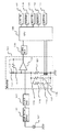
図1において、歩数計は、使用者の歩行(走行も含む。)を検出して該歩行に対応する電荷の信号(歩行信号)を出力する加速度センサ101、加速度センサ101からの電荷の歩行信号をこれに対応する電圧の歩行信号に変換して出力する電荷−電圧変換手段102、電荷−電圧変換手段102からの信号からノイズを除去した歩行信号を出力するフィルタ手段103、フィルタ手段103からの歩行信号を増幅して出力する増幅手段104、増幅手段104からの歩行信号を波形整形して二値のデジタル信号形式の歩行信号を出力する二値化手段105を備えている。尚、加速度センサ101は、加速度に応じた電荷を発生する素子である。
FIG. 1 is a block diagram of a pedometer according to a first embodiment of the present invention, and is configured to be used while being worn on an arm or waist or held in a bag or the like. This is an example of a pedometer.
In FIG. 1, the pedometer detects the user's walking (including running) and outputs a charge signal (walking signal) corresponding to the walking, and a charge walking signal from the
また、歩数計は、二値化手段105からの歩行信号に基づいて所定時間当たりの歩数(歩行ピッチ)及び歩数を算出すると共に増幅手段104の利得を制御する中央処理装置(CPU)106、入力スイッチ等によって構成された入力手段107、液晶表示装置等によって構成され歩数等を表示する表示手段108、圧電スピーカ等によって構成され設定完了や異常等を音で報知する報音手段109、基準クロック信号を生成する発振手段110、フラッシュメモリ等の不揮発性メモリによって構成された記憶手段111を備えている。
The pedometer calculates the number of steps per predetermined time (walking pitch) and the number of steps based on the walking signal from the
増幅手段104は、演算増幅器112、抵抗器113、120、利得制御用抵抗器118、119、コンデンサ114、利得制御用スイッチ手段115を備えている。スイッチ手段115は、抵抗器120に対して並列接続された複数の利得制御用スイッチ116、117を備えている。スイッチ116、117は各々、利得制御用抵抗器118、119と直列に接続されている。各スイッチ116、117には、機械的なスイッチでもよく又、半導体スイッチでもよい。
The amplification means 104 includes an operational amplifier 112,
記憶手段111には、CPU106が実行するプログラム、通常の歩行が行われたときに得られる所定の歩行ピッチの範囲を示す歩行ピッチの上限値及び下限値、増幅手段104の利得設定が行われたときのスイッチ手段115(換言すれば、スイッチ116、117)の開閉状態が記憶されている。前記所定の歩行ピッチの範囲は、その範囲の上限値が下限値の2倍未満になるように設定する(例えば、下限値が80歩/分で上限値が135歩/分)。これにより、一歩おきに歩行を検出できないような事態が発生した場合には検出異常と判定できる。
In the storage unit 111, a program executed by the
ここで、センサ101、電荷−電圧変換手段102、フィルタ手段103、増幅手段104及び二値化手段105は、歩行を検出して対応する歩行信号を出力する歩行検出手段を構成している。CPU106は、二値化手段105からの歩行信号に基づいて歩行ピッチ及び歩数を算出する算出手段、歩行信号に基づいて算出される歩行ピッチが前記所定のピッチ範囲内になるように前記歩行検出手段の検出感度(具体的には増幅手段104の利得)を制御する制御手段を構成している。また、抵抗器113、118〜120は抵抗回路を構成している。
Here, the
図2は、本発明の第1の実施の形態に係る歩数計の処理を示すフローチャートであり、主としてCPU106が記憶手段111に記憶されたプログラムを実行することによって行う処理を示している。
また、図3は、本第1の実施の形態におけるタイミング図であり、増幅手段104の利得が適正に調整制御されている場合(調整OK)のタイミング図と、利得の調整制御が不適切な場合(調整NG)のタイミング図を並記している。
FIG. 2 is a flowchart showing processing of the pedometer according to the first embodiment of the present invention, and shows processing mainly performed by the
FIG. 3 is a timing chart in the first embodiment. The timing chart when the gain of the amplification means 104 is appropriately adjusted and controlled (adjustment OK) and the gain adjustment control are inappropriate. The timing diagram of the case (adjustment NG) is shown side by side.
使用者の歩行に応じた歩行衝撃が発生する毎に、センサ101がこれを検出して対応する歩行信号を出力し、増幅手段104は、電荷−電圧変換手段102及びフィルタ手段103を介して入力された歩行信号を増幅してアナログ形式の歩行信号を出力する。二値化手段105は増幅手段104からのアナログ形式の歩行信号をデジタル形式の歩行信号に変換して出力する。CPU106は、二値化手段105からの最新の歩行信号を含む所定数の歩行信号に基づいて歩行ピッチを算出する。
Each time a walking impact occurs according to the user's walking, the
増幅手段104の利得制御が適正に成されている場合には、CPU106は各歩行信号(換言すれば各歩行衝撃)に対応する歩行ピッチを算出することができる。図3では、利得制御が適正に成されている場合に算出した歩行ピッチは、92〜99歩/分である。利得制御が不適正な場合には、歩行衝撃に対応する歩行信号が検出されない場合があるため、歩行ピッチが47歩/分と通常歩行時の歩行ピッチに比べて大幅に小さくなっている。したがって、前記歩行ピッチの所定範囲を例えば80歩/分〜135歩/分に設定しておくことにより、増幅手段104の利得が適正に制御されたか否かの判別が可能になる。
When the gain control of the amplifying
以下、図1〜図3を用いて、本第1の実施の形態に係る歩数計の動作を説明する。
先ず、使用者は、腕などに歩数計を装着して動作を開始する。このときCPU106は、購入後初めて使用するときや設定情報をリセットして使用する場合等のように、増幅手段104の利得調整の情報等が記憶手段に記憶されていない場合、調整が未完了であることを表す調整完了マークを表示手段108に表示する(ステップS200)。
Hereinafter, the operation of the pedometer according to the first embodiment will be described with reference to FIGS.
First, a user attaches a pedometer to an arm or the like and starts an operation. At this time, the
この状態で、使用者が入力手段107を操作することによって歩数計の動作モードを調整モードにセットし(ステップS201)、歩行を開始すると(ステップS202)、加速度センサ101は、使用者の歩行(図3の歩行衝撃)を検出する毎に該歩行に対応する電荷の信号(歩行信号)を出力する。
電荷−電圧変換手段102はセンサ101からの電荷の歩行信号を、対応する電圧の歩行信号に変換して出力する。フィルタ手段103は、電荷−電圧変換手段102からの信号からノイズを除去した歩行信号を出力する。
In this state, the user operates the input means 107 to set the operation mode of the pedometer to the adjustment mode (step S201), and when walking starts (step S202), the
The charge-voltage conversion means 102 converts the charge walking signal from the
増幅手段104のスイッチ116、117は、初期状態では開状態となっており、したがって、初期状態の増幅手段104の利得は最小となっている。増幅手段104は、フィルタ手段103からの歩行信号を、最小の利得によって増幅し、二値化手段105に出力する。尚、CPU106は、増幅手段104の利得を制御する場合、後述するように、増幅手段104の利得が最小値から順に大きくなるようにスイッチ116、117を開閉制御する。即ち、CPU106は、増幅手段104の利得が単調に変化するように制御する。
二値化手段105は、増幅手段104からの歩行信号を波形整形してデジタル信号形式の歩行信号を出力する。
The
The binarizing means 105 shapes the walking signal from the amplifying means 104 and outputs a walking signal in a digital signal format.
CPU106は、二値化手段105からの歩行信号を検出したか否か即ち二値化手段から歩行信号が入力されたか否かを判断し(ステップS203)、二値化手段105からの歩行信号を検出していないと判断した場合には、所定時間経過したか否か、即ち所定時間(換言すれば所定歩数)連続して歩行信号を検出していないかを判断し(ステップS204)、所定時間経過していないと判断した場合にはスイッチ116、117を開閉制御することによって増幅手段104の利得を大きくした後、処理ステップS203に戻る。
The
CPU106は、処理ステップS204において所定時間経過したと判断した場合、増幅手段104の利得を調整制御しても適正な感度調整ができなかった旨を報音手段109から報知する(ステップS206)。
使用者が入力手段107を操作して、再度調整実行(リトライ)を指定すると、CPU106は前記リトライ指示を検出して(ステップS207)、処理ステップS200へ戻って前記処理を繰り返す。CPU106は、処理ステップ207において、入力手段107からリトライ指示が入力されないと判断した場合には感度調整制御処理を終了する。
If the
When the user operates the
一方、CPU106は、処理ステップS203において、二値化手段105からの歩行信号を検出したと判断すると、前記歩行信号を含む所定数の歩行信号に基づいて前記歩行信号に対応するピッチを算出し、該算出したピッチが記憶手段111に記憶されている所定のピッチ範囲内か否かを判断する(ステップS208)。
CPU106は、処理ステップS208において、前記算出したピッチが所定ピッチ範囲内と判断した後、所定時間経過した(即ち、所定時間(所定歩数)連続して歩行信号を検出した)と判断すると(ステップS209)、感度調整が正常に完了した旨の報知(OK報知)を報音手段109から行う(ステップS210)。
On the other hand, when determining that the walking signal from the binarization means 105 is detected in the processing step S203, the
In step S208, the
次に、CPU106は、表示手段108に表示していた調整未完了マークを消灯した後(ステップS211)、前記利得調整を行うために開閉制御したスイッチ手段115の開閉設定状態(スイッチ116、117の開閉設定状態)の情報を記憶手段111に保存して処理を終了する(ステップS212)。記憶手段111は不揮発性メモリによって構成されているため、電源を切っても前記記憶した情報は消えずに保存される。
CPU106は、一旦歩数計測が終了した後に電源起動して再び歩数計測開始した場合等には、記憶手段111に記憶した開閉状態になるようにスイッチ手段115(具体的にはスイッチ116、117)を開閉制御して増幅手段104の利得を適正な値にした後、歩数計測を開始する。
Next, after the
The
CPU106は、処理ステップS208において前記算出したピッチが所定ピッチ範囲外と判断した場合には、スイッチ手段115(具体的にはスイッチ116、117)を開閉制御することによって増幅手段104の利得を変更し(この場合、利得が大きくなるようにスイッチ116、117を開閉制御する。)、ステップS203へ戻って前記処理を繰り返す(ステップS213)。
歩行検出手段の検出感度調整終了後、入力手段107の操作によって歩数計測モードへ移行して、歩数計測動作を開始する。
When the
After the detection sensitivity adjustment of the walking detection means is completed, the operation is shifted to the step count measurement mode by the operation of the input means 107, and the step count measurement operation is started.
以上のように本第1の実施の形態に係る歩数計によれば、構成要素のバラツキや個人差の影響を抑制して、より正確な歩数計測を行うことが可能になる。
また、調整時の歩行ピッチを規定しないため、使用者の普段の歩行状態で調整することが可能となり、使用者に違和感を与えることがないという効果を奏する。
また、より普段の歩行に合った条件で調整することが出来るため、実際の歩行検出において検出精度が向上するという効果を奏する。
As described above, according to the pedometer according to the first embodiment, it is possible to perform more accurate step count measurement while suppressing the influence of component variations and individual differences.
In addition, since the walking pitch at the time of adjustment is not defined, it is possible to adjust in the normal walking state of the user, and there is an effect that the user does not feel uncomfortable.
In addition, since the adjustment can be performed under conditions more suitable for normal walking, the detection accuracy is improved in actual walking detection.
また、増幅手段104の利得を切り替えることによって、前記歩行信号に基づいて算出される歩行ピッチが所定範囲内になるように歩行検出手段の検出感度を制御するように構成しているため、耐ノイズ性に優れるという効果をも奏する。
尚、本第1の実施の形態においては、センサ101として加速度センサを使用したが、振動によってスイッチが開閉動作する機械的なスイッチを有するセンサを使用してもよい。
In addition, by switching the gain of the amplification means 104, the detection sensitivity of the walking detection means is controlled so that the walking pitch calculated based on the walking signal is within a predetermined range. There is also an effect that it is excellent in properties.
In the first embodiment, an acceleration sensor is used as the
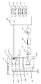
図4は、本発明の第2の実施の形態に係る歩数計のブロック図であり、図1と同一部分には同一符号を付している。
前記第1の実施の形態においては、歩行検出手段の感度調整のために、増幅手段104の利得を調整するようにしたが、本第2の実施の形態では、電荷−電圧変換手段の利得を調整制御するように構成している。
FIG. 4 is a block diagram of a pedometer according to the second embodiment of the present invention. The same reference numerals are given to the same parts as those in FIG.
In the first embodiment, the gain of the amplifying means 104 is adjusted to adjust the sensitivity of the walking detection means. In the second embodiment, the gain of the charge-voltage converting means is adjusted. It is configured to perform adjustment control.
図4において、歩数計は、使用者の歩行(走行も含む。)を検出して該歩行に対応する電荷の信号(歩行信号)を出力する加速度センサ101、加速度センサ101からの電荷の歩行信号に対応する電圧の歩行信号に変換して出力する電荷−電圧変換手段401、電荷−電圧変換手段401からの信号からノイズを除去して歩行信号を出力するフィルタ手段103、フィルタ手段103からの歩行信号を増幅して出力する増幅手段402、増幅手段402からのアナログ信号形式の歩行信号を波形整形して二値のデジタル信号形式の歩行信号を出力する二値化手段105、二値化手段105からの歩行信号に基づいて歩行ピッチ及び歩数を算出すると共に電荷−電圧変換手段401の利得を制御する中央処理装置(CPU)403、入力手段107、表示手段108、報音手段109、発振手段110、記憶手段111を備えている。
In FIG. 4, the pedometer detects the user's walking (including running) and outputs a charge signal (walking signal) corresponding to the walking, and a charge walking signal from the
加速度センサ101は、加速度に応じた電荷を発生する素子である。ある加速度に対し、加速度センサ101が電荷Qを発生したとき、その出力を容量Cのコンデンサで受けた場合、前記コンデンサの両端電圧はQ/Cで表すことが出来る。加速度センサ101のセンサ性能のばらつきで、単位加速度あたりに発生する電荷が、一定範囲でばらついた場合、電荷を受けるコンデンサ回路の容量を一定範囲で調節することにより、歩行の検出感度を一定に保つことが可能になる。
使用者に適した検出感度に調整する場合も前記同様にコンデンサ回路の容量Cを調節することで、歩行の検出感度を調整することが可能になる。これが、本第2の実施の形態における歩行感度調整の基本原理である。
The
In the case of adjusting the detection sensitivity suitable for the user, it is possible to adjust the detection sensitivity of walking by adjusting the capacitance C of the capacitor circuit as described above. This is the basic principle of the walking sensitivity adjustment in the second embodiment.
電荷−電圧変換手段401は、演算増幅器404、演算増幅器404の入出力間に接続された抵抗器405、抵抗器405に対して並列接続されたコンデンサ406、コンデンサ406に対して並列接続された利得制御用の複数のコンデンサ407、408、コンデンサ407、408に直列接続された複数のスイッチ410、411を有するスイッチ手段409を備えている。
The charge-voltage conversion means 401 includes an
ここで、加速度センサ101、電荷−電圧変換手段401、フィルタ手段103、増幅手段402及び二値化手段105は、歩行を検出して対応する歩行信号を出力する歩行検出手段を構成している。また、CPU403は、二値化手段105からの歩行信号に基づいて歩行ピッチ及び歩数を算出する算出手段、歩行信号に基づいて算出される歩数が所定範囲内になるように前記歩行検出手段の検出感度(具体的には、電荷−電圧変換手段401の利得)を制御する制御手段を構成している。
Here, the
本第2の実施の形態と前記第1の実施の形態の相違点は、前記第1の実施の形態では、利得が所定値に固定された電荷−電圧変換手段102を用いると共に利得が可変な増幅手段104を用いたのに対して、本第2の実施の形態では、利得が可変な電荷−電圧変換手段を用いると共に利得が所定値に固定された増幅手段402を用いている点である。
その他の構成は同一であり、従って、CPU403が電荷−電圧変換手段401の利得を制御するように動作する点以外は、CPU403の処理内容やタイミングは、図2、図3と同様である。
The difference between the second embodiment and the first embodiment is that, in the first embodiment, the charge-voltage conversion means 102 whose gain is fixed to a predetermined value is used and the gain is variable. Whereas the amplifying means 104 is used, the second embodiment uses a charge-voltage converting means whose gain is variable and an amplifying means 402 whose gain is fixed to a predetermined value. .
The other configurations are the same, and therefore the processing contents and timing of the
以下、本第2の実施の形態について、図4を用いて(必要に応じて図1〜図3を参照して)、前記第1の実施の形態と相違する部分について動作を説明する。
使用者が入力手段107を操作して調整モードにセットして、歩行開始すると、加速度センサ101は、使用者の歩行(図3の歩行衝撃)を検出する毎に該歩行に対応する電荷の歩行信号を出力する。
Hereinafter, the operation of the second embodiment will be described with reference to FIG. 4 (refer to FIGS. 1 to 3 as necessary) for the parts different from the first embodiment.
When the user operates the input means 107 to set the adjustment mode and starts walking, the
電荷−電圧変換手段401は加速度センサ101からの歩行信号を、対応する電圧の歩行信号に変換して出力する。電荷−電圧変換手段401のスイッチ410、411は、初期状態では開状態となっており、したがって、初期状態の電荷−電圧変換手段401の利得は最小となっている。電荷−電圧変換手段401は、加速度センサ101からの歩行信号を、最小の利得によって増幅し、フィルタ手段103に出力する。
The charge-voltage conversion means 401 converts the walking signal from the
尚、CPU403は、電荷−電圧変換手段401の利得を制御する場合、電荷−電圧変換手段401の利得が最小値から順に大きくなるようにスイッチ410、411を開閉制御する。即ち、電荷−電圧変換手段401の利得が単調に変化するようにスイッチ410、411を開閉制御する。
When controlling the gain of the charge-
フィルタ手段103は、電荷−電圧変換手段401からの信号からノイズを除去した歩行信号を出力する。増幅手段402は、フィルタ手段103からの歩行信号を所定利得で増幅し、アナログ信号形式の歩行信号を二値化手段105に出力する。二値化手段105は、増幅手段402からのアナログ形式の歩行信号を波形整形してデジタル信号形式の歩行信号を出力する。
The filter means 103 outputs a walking signal obtained by removing noise from the signal from the charge-voltage conversion means 401. The amplifying
CPU403は、図2と同様の処理を行うことにより、二値化手段105から出力される歩行信号に基づいて算出した歩行ピッチが、記憶手段111に記憶した所定の歩行ピッチ範囲内に入るように電荷−電圧変換手段401のスイッチ手段409(具体的にはスイッチ410、411)を開閉制御する。
The
CPU106は、前記算出した歩行ピッチが前記所定の歩行ピッチ内になったときに利得調整を終了するが、そのときのスイッチ手段409(具体的にはスイッチ410、411)の開閉設定状態の情報を記憶手段111に保存して処理を終了する。歩行検出手段の検出感度調整終了後、入力手段107の操作によって歩数計測モードへ移行して、歩数計測動作を開始する。
CPU106は、一旦歩数計測が終了した後に電源起動して再び歩数計測開始した場合等には、記憶手段111に記憶した開閉状態になるようにスイッチ手段409を開閉制御して電荷−電圧変換手段401の利得を適正な値にした後、歩数計測を開始する。
The
The
以上述べたように本第2の実施の形態によれば、前記第1の実施の形態と同様に、歩数計の構成要素のバラツキや個人差の影響を抑制して、より正確な歩数計測を行うことが可能になる等の効果を奏するばかりでなく、コンデンサを切り替えるようにしているため、容量値の小さなコンデンサを複数使用することにより、利得の微調整が可能、したがって、感度の微調整が可能になるという効果をも奏する。 As described above, according to the second embodiment, as in the first embodiment, it is possible to suppress the influence of variations in pedometer components and individual differences, and more accurate step count measurement. In addition to the effects such as being able to be performed, since the capacitor is switched, the gain can be finely adjusted by using a plurality of capacitors having a small capacitance value, and therefore the sensitivity can be finely adjusted. There is also an effect that it becomes possible.
腕に装着して使用する方式の歩数計、腰に装着して使用する方式の歩数計、バッグ等に収納して保持した状態で使用する方式の歩数計等、各種の歩数計に適用可能である。 Applicable to various pedometers such as pedometers that are worn on the wrist, pedometers that are worn on the waist, and pedometers that are used while stored in a bag. is there.
101・・・歩行検出手段を構成するセンサ
102、401・・・歩行検出手段を構成する電荷−電圧変換手段
103・・・歩行検出手段を構成するフィルタ手段
104、402・・・歩行検出手段を構成する増幅手段
105・・・歩行検出手段を構成する二値化手段
106、403・・・算出手段及び制御手段を構成するCPU
107・・・入力手段
108・・・表示手段
109・・・報音手段
110・・・発振手段
111・・・記憶手段
113、118〜120・・・抵抗回路を構成する抵抗器
115、409・・・スイッチ手段
116、117、410、411・・・スイッチ
406〜408・・・コンデンサ回路を構成するコンデンサ
101 ...
107 ... input means 108 ... display means 109 ... sound reporting means 110 ... oscillation means 111 ... storage means 113, 118 to 120 ...
Claims (7)
前記歩行検出手段は、走行を含む歩行を検出して対応する歩行信号を出力するセンサと、前記センサからの歩行信号を増幅し歩行信号として出力する増幅手段とを備え、
前記制御手段は、前記増幅手段からの歩行信号に基づいて前記算出手段が算出する歩行ピッチが所定範囲内になるように前記増幅手段の利得を制御することを特徴とする歩数計。 A walk detecting means for detecting a walk including running and outputting a corresponding walk signal; a calculating means for calculating a number of steps and a walk pitch based on the walk signal; and a walk pitch calculated based on the walk signal is predetermined. Control means for controlling the detection sensitivity of the walking detection means so as to be within a range,
The walking detection means includes a sensor that detects walking including running and outputs a corresponding walking signal; and an amplifying means that amplifies the walking signal from the sensor and outputs the walking signal.
The control means controls the gain of the amplifying means so that the walking pitch calculated by the calculating means is within a predetermined range based on a walking signal from the amplifying means.
前記制御手段は、前記スイッチ手段を開閉制御して前記抵抗回路の抵抗値を制御することにより、前記増幅手段の利得を制御することを特徴とする請求項1記載の歩数計。 The amplifying means comprises a resistance circuit having a plurality of resistors for determining a gain, and switch means for controlling the resistance value of the resistance circuit,
2. The pedometer according to claim 1, wherein the control means controls the gain of the amplifying means by controlling opening and closing of the switch means to control a resistance value of the resistance circuit.
前記歩行検出手段は、走行を含む歩行を検出して対応する電荷の歩行信号を出力するセンサと、前記センサからの歩行信号を対応する電圧の歩行信号に変換し出力する電荷−電圧変換手段とを備え、
前記制御手段は、前記電荷−電圧変換手段からの歩行信号に基づいて前記算出手段が算出する歩行ピッチが所定範囲内になるように前記電荷−電圧変換手段の利得を制御することを特徴とする歩数計。 A walk detecting means for detecting a walk including running and outputting a corresponding walk signal; a calculating means for calculating a number of steps and a walk pitch based on the walk signal; and a walk pitch calculated based on the walk signal is predetermined. Control means for controlling the detection sensitivity of the walking detection means so as to be within a range,
The walking detection means detects a walking including running and outputs a corresponding charge walking signal, and a charge-voltage converting means that converts the walking signal from the sensor into a corresponding voltage walking signal and outputs the same. With
The control means controls the gain of the charge-voltage conversion means so that a walking pitch calculated by the calculation means is within a predetermined range based on a walking signal from the charge-voltage conversion means. Pedometer.
前記制御手段は、前記スイッチ手段を開閉制御して前記コンデンサ回路の容量値を制御することにより、前記電荷−電圧変換手段の利得を制御することを特徴とする請求項3記載の歩数計。 The charge-voltage conversion means comprises a capacitor circuit having a plurality of capacitors for determining gain, and switch means for controlling the capacitance value of the capacitor circuit,
4. The pedometer according to claim 3, wherein the control means controls the gain of the charge-voltage conversion means by controlling opening and closing of the switch means to control a capacitance value of the capacitor circuit.
前記制御手段は、開閉制御した前記スイッチ手段の開閉状態を前記記憶手段に記憶し、歩数計測開始時に、前記記憶手段に記憶した開閉状態になるように前記スイッチ手段を制御することを特徴とする請求項2又は4記載の歩数計。 Comprising a storage means,
The control means stores the open / close state of the switch means subjected to open / close control in the storage means, and controls the switch means so as to be in the open / close state stored in the storage means at the start of step count measurement. The pedometer according to claim 2 or 4.
Priority Applications (3)
| Application Number | Priority Date | Filing Date | Title |
|---|---|---|---|
| JP2006232185A JP4995513B2 (en) | 2006-08-29 | 2006-08-29 | Pedometer |
| US11/895,491 US20080056429A1 (en) | 2006-08-29 | 2007-08-23 | Pedometer |
| EP07253352A EP1895276A1 (en) | 2006-08-29 | 2007-08-24 | Pedometer |
Applications Claiming Priority (1)
| Application Number | Priority Date | Filing Date | Title |
|---|---|---|---|
| JP2006232185A JP4995513B2 (en) | 2006-08-29 | 2006-08-29 | Pedometer |
Publications (3)
| Publication Number | Publication Date |
|---|---|
| JP2008059043A JP2008059043A (en) | 2008-03-13 |
| JP2008059043A5 JP2008059043A5 (en) | 2009-05-07 |
| JP4995513B2 true JP4995513B2 (en) | 2012-08-08 |
Family
ID=38731176
Family Applications (1)
| Application Number | Title | Priority Date | Filing Date |
|---|---|---|---|
| JP2006232185A Expired - Fee Related JP4995513B2 (en) | 2006-08-29 | 2006-08-29 | Pedometer |
Country Status (3)
| Country | Link |
|---|---|
| US (1) | US20080056429A1 (en) |
| EP (1) | EP1895276A1 (en) |
| JP (1) | JP4995513B2 (en) |
Families Citing this family (10)
| Publication number | Priority date | Publication date | Assignee | Title |
|---|---|---|---|---|
| US9062976B2 (en) * | 2008-07-29 | 2015-06-23 | Kyocera Corporation | Portable electronic device including a pedometer function with suppression of counting errors |
| US10018487B2 (en) * | 2011-06-15 | 2018-07-10 | Honeywell International Inc. | Methods and systems for activating sealed sensors in the field |
| WO2016191590A1 (en) * | 2015-05-28 | 2016-12-01 | Nike, Inc. | Athletic activity monitoring device with energy capture |
| EP3302723B1 (en) | 2015-05-28 | 2020-03-11 | Nike Innovate C.V. | Athletic activity monitoring device with energy capture |
| WO2016191580A1 (en) | 2015-05-28 | 2016-12-01 | Nike, Inc. | Athletic activity monitoring device with energy capture |
| WO2016191571A1 (en) | 2015-05-28 | 2016-12-01 | Nike, Inc. | Athletic activity monitoring device with energy capture |
| EP3302725B1 (en) | 2015-05-28 | 2020-03-18 | Nike Innovate C.V. | Athletic activity monitoring device with energy capture |
| CN107921305B (en) | 2015-05-28 | 2019-11-29 | 耐克创新有限合伙公司 | The sports monitoring device of energy can be captured |
| WO2016191577A1 (en) | 2015-05-28 | 2016-12-01 | Nike, Inc. | Athletic activity monitoring device with energy capture |
| WO2016191593A1 (en) | 2015-05-28 | 2016-12-01 | Nike, Inc. | Athletic activity monitoring device with energy capture |
Family Cites Families (8)
| Publication number | Priority date | Publication date | Assignee | Title |
|---|---|---|---|---|
| US4555668A (en) * | 1983-10-14 | 1985-11-26 | American Microsystems, Inc. | Gain amplifier |
| JP2518217Y2 (en) * | 1988-04-18 | 1996-11-27 | カシオ計算機株式会社 | Pedometer |
| US4962469A (en) * | 1988-04-18 | 1990-10-09 | Casio Computer Co., Ltd. | Exercise measuring instrument |
| JP3220271B2 (en) * | 1993-02-22 | 2001-10-22 | セイコーインスツルメンツ株式会社 | Pedometer with pulse meter |
| GB0005010D0 (en) * | 2000-03-01 | 2000-04-19 | Spinnaker Int Ltd | Electronic pedometer expected behaviour detector and security system incorporating such a detector |
| JP3801163B2 (en) * | 2003-03-07 | 2006-07-26 | セイコーエプソン株式会社 | Body motion detection device, pitch meter, pedometer, wristwatch type information processing device, control method, and control program |
| JP4296115B2 (en) * | 2004-03-30 | 2009-07-15 | セイコーインスツル株式会社 | Electronic pedometer |
| JP4785553B2 (en) * | 2006-02-16 | 2011-10-05 | セイコーインスツル株式会社 | Pedometer |
-
2006
- 2006-08-29 JP JP2006232185A patent/JP4995513B2/en not_active Expired - Fee Related
-
2007
- 2007-08-23 US US11/895,491 patent/US20080056429A1/en not_active Abandoned
- 2007-08-24 EP EP07253352A patent/EP1895276A1/en not_active Withdrawn
Also Published As
| Publication number | Publication date |
|---|---|
| US20080056429A1 (en) | 2008-03-06 |
| JP2008059043A (en) | 2008-03-13 |
| EP1895276A1 (en) | 2008-03-05 |
Similar Documents
| Publication | Publication Date | Title |
|---|---|---|
| JP4995513B2 (en) | Pedometer | |
| JP4885676B2 (en) | Pedometer | |
| US7526404B2 (en) | Pedometer | |
| JP4622827B2 (en) | Pedometer | |
| EP3006913A1 (en) | Physical quantity sensor adjustment method, and physical quantity sensor | |
| JP2008058010A (en) | Pedometer | |
| EP1821071A1 (en) | Step number measuring apparatus | |
| JP4885664B2 (en) | Pedometer | |
| JP5014023B2 (en) | Pedometer | |
| JP4405200B2 (en) | Walking time calculation device and walking distance calculation device using the same | |
| JP5001669B2 (en) | Pedometer | |
| JP4476667B2 (en) | Pedometer | |
| JP6100299B2 (en) | Step detection device, step detection method, and computer program | |
| JP4939962B2 (en) | Pedometer | |
| JP4995594B2 (en) | Pedometer | |
| JP4296115B2 (en) | Electronic pedometer | |
| JP5230219B2 (en) | Pedometer | |
| JP4945258B2 (en) | Pedometer | |
| US8131500B2 (en) | Pedometer | |
| JP2697911B2 (en) | Pedometer | |
| US20080275669A1 (en) | Pedometer | |
| JP4990735B2 (en) | Pedometer | |
| JP5006169B2 (en) | Pedometer | |
| JP2010051548A (en) | Electronic device with pitch measuring function | |
| JP5006222B2 (en) | Pedometer |
Legal Events
| Date | Code | Title | Description |
|---|---|---|---|
| A521 | Written amendment |
Free format text: JAPANESE INTERMEDIATE CODE: A523 Effective date: 20090319 |
|
| A621 | Written request for application examination |
Free format text: JAPANESE INTERMEDIATE CODE: A621 Effective date: 20090319 |
|
| RD01 | Notification of change of attorney |
Free format text: JAPANESE INTERMEDIATE CODE: A7421 Effective date: 20091105 |
|
| RD01 | Notification of change of attorney |
Free format text: JAPANESE INTERMEDIATE CODE: A7421 Effective date: 20091113 |
|
| A131 | Notification of reasons for refusal |
Free format text: JAPANESE INTERMEDIATE CODE: A131 Effective date: 20111206 |
|
| A521 | Written amendment |
Free format text: JAPANESE INTERMEDIATE CODE: A523 Effective date: 20120201 |
|
| A131 | Notification of reasons for refusal |
Free format text: JAPANESE INTERMEDIATE CODE: A131 Effective date: 20120221 |
|
| A521 | Written amendment |
Free format text: JAPANESE INTERMEDIATE CODE: A523 Effective date: 20120412 |
|
| TRDD | Decision of grant or rejection written | ||
| A01 | Written decision to grant a patent or to grant a registration (utility model) |
Free format text: JAPANESE INTERMEDIATE CODE: A01 Effective date: 20120501 |
|
| A01 | Written decision to grant a patent or to grant a registration (utility model) |
Free format text: JAPANESE INTERMEDIATE CODE: A01 |
|
| A61 | First payment of annual fees (during grant procedure) |
Free format text: JAPANESE INTERMEDIATE CODE: A61 Effective date: 20120510 |
|
| FPAY | Renewal fee payment (event date is renewal date of database) |
Free format text: PAYMENT UNTIL: 20150518 Year of fee payment: 3 |
|
| R150 | Certificate of patent or registration of utility model |
Free format text: JAPANESE INTERMEDIATE CODE: R150 |
|
| LAPS | Cancellation because of no payment of annual fees |