JP4990794B2 - Thermal control fluid self-assembly - Google Patents
Thermal control fluid self-assembly Download PDFInfo
- Publication number
- JP4990794B2 JP4990794B2 JP2007548426A JP2007548426A JP4990794B2 JP 4990794 B2 JP4990794 B2 JP 4990794B2 JP 2007548426 A JP2007548426 A JP 2007548426A JP 2007548426 A JP2007548426 A JP 2007548426A JP 4990794 B2 JP4990794 B2 JP 4990794B2
- Authority
- JP
- Japan
- Prior art keywords
- support
- fluid
- cooling
- assembly
- microcomponent
- Prior art date
- Legal status (The legal status is an assumption and is not a legal conclusion. Google has not performed a legal analysis and makes no representation as to the accuracy of the status listed.)
- Expired - Fee Related
Links
Images


Classifications
-
- H—ELECTRICITY
- H01—ELECTRIC ELEMENTS
- H01L—SEMICONDUCTOR DEVICES NOT COVERED BY CLASS H10
- H01L24/00—Arrangements for connecting or disconnecting semiconductor or solid-state bodies; Methods or apparatus related thereto
- H01L24/93—Batch processes
- H01L24/95—Batch processes at chip-level, i.e. with connecting carried out on a plurality of singulated devices, i.e. on diced chips
-
- H—ELECTRICITY
- H01—ELECTRIC ELEMENTS
- H01L—SEMICONDUCTOR DEVICES NOT COVERED BY CLASS H10
- H01L25/00—Assemblies consisting of a plurality of individual semiconductor or other solid state devices ; Multistep manufacturing processes thereof
- H01L25/50—Multistep manufacturing processes of assemblies consisting of devices, each device being of a type provided for in group H01L27/00 or H01L29/00
-
- H—ELECTRICITY
- H01—ELECTRIC ELEMENTS
- H01L—SEMICONDUCTOR DEVICES NOT COVERED BY CLASS H10
- H01L2224/00—Indexing scheme for arrangements for connecting or disconnecting semiconductor or solid-state bodies and methods related thereto as covered by H01L24/00
- H01L2224/80—Methods for connecting semiconductor or other solid state bodies using means for bonding being attached to, or being formed on, the surface to be connected
- H01L2224/83—Methods for connecting semiconductor or other solid state bodies using means for bonding being attached to, or being formed on, the surface to be connected using a layer connector
- H01L2224/8319—Arrangement of the layer connectors prior to mounting
- H01L2224/83192—Arrangement of the layer connectors prior to mounting wherein the layer connectors are disposed only on another item or body to be connected to the semiconductor or solid-state body
-
- H—ELECTRICITY
- H01—ELECTRIC ELEMENTS
- H01L—SEMICONDUCTOR DEVICES NOT COVERED BY CLASS H10
- H01L2224/00—Indexing scheme for arrangements for connecting or disconnecting semiconductor or solid-state bodies and methods related thereto as covered by H01L24/00
- H01L2224/93—Batch processes
- H01L2224/95—Batch processes at chip-level, i.e. with connecting carried out on a plurality of singulated devices, i.e. on diced chips
- H01L2224/95053—Bonding environment
- H01L2224/95085—Bonding environment being a liquid, e.g. for fluidic self-assembly
-
- H—ELECTRICITY
- H01—ELECTRIC ELEMENTS
- H01L—SEMICONDUCTOR DEVICES NOT COVERED BY CLASS H10
- H01L2224/00—Indexing scheme for arrangements for connecting or disconnecting semiconductor or solid-state bodies and methods related thereto as covered by H01L24/00
- H01L2224/93—Batch processes
- H01L2224/95—Batch processes at chip-level, i.e. with connecting carried out on a plurality of singulated devices, i.e. on diced chips
- H01L2224/9512—Aligning the plurality of semiconductor or solid-state bodies
- H01L2224/95136—Aligning the plurality of semiconductor or solid-state bodies involving guiding structures, e.g. shape matching, spacers or supporting members
-
- H—ELECTRICITY
- H01—ELECTRIC ELEMENTS
- H01L—SEMICONDUCTOR DEVICES NOT COVERED BY CLASS H10
- H01L2224/00—Indexing scheme for arrangements for connecting or disconnecting semiconductor or solid-state bodies and methods related thereto as covered by H01L24/00
- H01L2224/93—Batch processes
- H01L2224/95—Batch processes at chip-level, i.e. with connecting carried out on a plurality of singulated devices, i.e. on diced chips
- H01L2224/9512—Aligning the plurality of semiconductor or solid-state bodies
- H01L2224/95143—Passive alignment, i.e. self alignment, e.g. using surface energy, chemical reactions, thermal equilibrium
- H01L2224/95144—Magnetic alignment, i.e. using permanent magnetic parts in the semiconductor or solid-state body
-
- H—ELECTRICITY
- H01—ELECTRIC ELEMENTS
- H01L—SEMICONDUCTOR DEVICES NOT COVERED BY CLASS H10
- H01L2224/00—Indexing scheme for arrangements for connecting or disconnecting semiconductor or solid-state bodies and methods related thereto as covered by H01L24/00
- H01L2224/93—Batch processes
- H01L2224/95—Batch processes at chip-level, i.e. with connecting carried out on a plurality of singulated devices, i.e. on diced chips
- H01L2224/9512—Aligning the plurality of semiconductor or solid-state bodies
- H01L2224/95143—Passive alignment, i.e. self alignment, e.g. using surface energy, chemical reactions, thermal equilibrium
- H01L2224/95145—Electrostatic alignment, i.e. polarity alignment with Coulomb charges
-
- H—ELECTRICITY
- H01—ELECTRIC ELEMENTS
- H01L—SEMICONDUCTOR DEVICES NOT COVERED BY CLASS H10
- H01L2924/00—Indexing scheme for arrangements or methods for connecting or disconnecting semiconductor or solid-state bodies as covered by H01L24/00
- H01L2924/01—Chemical elements
- H01L2924/01005—Boron [B]
-
- H—ELECTRICITY
- H01—ELECTRIC ELEMENTS
- H01L—SEMICONDUCTOR DEVICES NOT COVERED BY CLASS H10
- H01L2924/00—Indexing scheme for arrangements or methods for connecting or disconnecting semiconductor or solid-state bodies as covered by H01L24/00
- H01L2924/01—Chemical elements
- H01L2924/01006—Carbon [C]
-
- H—ELECTRICITY
- H01—ELECTRIC ELEMENTS
- H01L—SEMICONDUCTOR DEVICES NOT COVERED BY CLASS H10
- H01L2924/00—Indexing scheme for arrangements or methods for connecting or disconnecting semiconductor or solid-state bodies as covered by H01L24/00
- H01L2924/01—Chemical elements
- H01L2924/01013—Aluminum [Al]
-
- H—ELECTRICITY
- H01—ELECTRIC ELEMENTS
- H01L—SEMICONDUCTOR DEVICES NOT COVERED BY CLASS H10
- H01L2924/00—Indexing scheme for arrangements or methods for connecting or disconnecting semiconductor or solid-state bodies as covered by H01L24/00
- H01L2924/01—Chemical elements
- H01L2924/01015—Phosphorus [P]
-
- H—ELECTRICITY
- H01—ELECTRIC ELEMENTS
- H01L—SEMICONDUCTOR DEVICES NOT COVERED BY CLASS H10
- H01L2924/00—Indexing scheme for arrangements or methods for connecting or disconnecting semiconductor or solid-state bodies as covered by H01L24/00
- H01L2924/01—Chemical elements
- H01L2924/01019—Potassium [K]
-
- H—ELECTRICITY
- H01—ELECTRIC ELEMENTS
- H01L—SEMICONDUCTOR DEVICES NOT COVERED BY CLASS H10
- H01L2924/00—Indexing scheme for arrangements or methods for connecting or disconnecting semiconductor or solid-state bodies as covered by H01L24/00
- H01L2924/01—Chemical elements
- H01L2924/01027—Cobalt [Co]
-
- H—ELECTRICITY
- H01—ELECTRIC ELEMENTS
- H01L—SEMICONDUCTOR DEVICES NOT COVERED BY CLASS H10
- H01L2924/00—Indexing scheme for arrangements or methods for connecting or disconnecting semiconductor or solid-state bodies as covered by H01L24/00
- H01L2924/01—Chemical elements
- H01L2924/01033—Arsenic [As]
-
- H—ELECTRICITY
- H01—ELECTRIC ELEMENTS
- H01L—SEMICONDUCTOR DEVICES NOT COVERED BY CLASS H10
- H01L2924/00—Indexing scheme for arrangements or methods for connecting or disconnecting semiconductor or solid-state bodies as covered by H01L24/00
- H01L2924/01—Chemical elements
- H01L2924/01074—Tungsten [W]
-
- H—ELECTRICITY
- H01—ELECTRIC ELEMENTS
- H01L—SEMICONDUCTOR DEVICES NOT COVERED BY CLASS H10
- H01L2924/00—Indexing scheme for arrangements or methods for connecting or disconnecting semiconductor or solid-state bodies as covered by H01L24/00
- H01L2924/10—Details of semiconductor or other solid state devices to be connected
- H01L2924/102—Material of the semiconductor or solid state bodies
- H01L2924/1025—Semiconducting materials
- H01L2924/1026—Compound semiconductors
- H01L2924/1032—III-V
- H01L2924/10329—Gallium arsenide [GaAs]
-
- H—ELECTRICITY
- H01—ELECTRIC ELEMENTS
- H01L—SEMICONDUCTOR DEVICES NOT COVERED BY CLASS H10
- H01L2924/00—Indexing scheme for arrangements or methods for connecting or disconnecting semiconductor or solid-state bodies as covered by H01L24/00
- H01L2924/10—Details of semiconductor or other solid state devices to be connected
- H01L2924/11—Device type
- H01L2924/12—Passive devices, e.g. 2 terminal devices
- H01L2924/1204—Optical Diode
- H01L2924/12041—LED
-
- H—ELECTRICITY
- H01—ELECTRIC ELEMENTS
- H01L—SEMICONDUCTOR DEVICES NOT COVERED BY CLASS H10
- H01L2924/00—Indexing scheme for arrangements or methods for connecting or disconnecting semiconductor or solid-state bodies as covered by H01L24/00
- H01L2924/10—Details of semiconductor or other solid state devices to be connected
- H01L2924/11—Device type
- H01L2924/12—Passive devices, e.g. 2 terminal devices
- H01L2924/1204—Optical Diode
- H01L2924/12042—LASER
-
- H—ELECTRICITY
- H01—ELECTRIC ELEMENTS
- H01L—SEMICONDUCTOR DEVICES NOT COVERED BY CLASS H10
- H01L2924/00—Indexing scheme for arrangements or methods for connecting or disconnecting semiconductor or solid-state bodies as covered by H01L24/00
- H01L2924/10—Details of semiconductor or other solid state devices to be connected
- H01L2924/11—Device type
- H01L2924/14—Integrated circuits
-
- H—ELECTRICITY
- H01—ELECTRIC ELEMENTS
- H01L—SEMICONDUCTOR DEVICES NOT COVERED BY CLASS H10
- H01L2924/00—Indexing scheme for arrangements or methods for connecting or disconnecting semiconductor or solid-state bodies as covered by H01L24/00
- H01L2924/15—Details of package parts other than the semiconductor or other solid state devices to be connected
- H01L2924/151—Die mounting substrate
- H01L2924/1515—Shape
- H01L2924/15153—Shape the die mounting substrate comprising a recess for hosting the device
- H01L2924/15155—Shape the die mounting substrate comprising a recess for hosting the device the shape of the recess being other than a cuboid
-
- H—ELECTRICITY
- H01—ELECTRIC ELEMENTS
- H01L—SEMICONDUCTOR DEVICES NOT COVERED BY CLASS H10
- H01L2924/00—Indexing scheme for arrangements or methods for connecting or disconnecting semiconductor or solid-state bodies as covered by H01L24/00
- H01L2924/15—Details of package parts other than the semiconductor or other solid state devices to be connected
- H01L2924/151—Die mounting substrate
- H01L2924/15165—Monolayer substrate
-
- H—ELECTRICITY
- H01—ELECTRIC ELEMENTS
- H01L—SEMICONDUCTOR DEVICES NOT COVERED BY CLASS H10
- H01L2924/00—Indexing scheme for arrangements or methods for connecting or disconnecting semiconductor or solid-state bodies as covered by H01L24/00
- H01L2924/19—Details of hybrid assemblies other than the semiconductor or other solid state devices to be connected
- H01L2924/1901—Structure
- H01L2924/1904—Component type
- H01L2924/19041—Component type being a capacitor
-
- H—ELECTRICITY
- H01—ELECTRIC ELEMENTS
- H01L—SEMICONDUCTOR DEVICES NOT COVERED BY CLASS H10
- H01L2924/00—Indexing scheme for arrangements or methods for connecting or disconnecting semiconductor or solid-state bodies as covered by H01L24/00
- H01L2924/19—Details of hybrid assemblies other than the semiconductor or other solid state devices to be connected
- H01L2924/1901—Structure
- H01L2924/1904—Component type
- H01L2924/19042—Component type being an inductor
-
- H—ELECTRICITY
- H01—ELECTRIC ELEMENTS
- H01L—SEMICONDUCTOR DEVICES NOT COVERED BY CLASS H10
- H01L2924/00—Indexing scheme for arrangements or methods for connecting or disconnecting semiconductor or solid-state bodies as covered by H01L24/00
- H01L2924/19—Details of hybrid assemblies other than the semiconductor or other solid state devices to be connected
- H01L2924/1901—Structure
- H01L2924/1904—Component type
- H01L2924/19043—Component type being a resistor
-
- H—ELECTRICITY
- H01—ELECTRIC ELEMENTS
- H01L—SEMICONDUCTOR DEVICES NOT COVERED BY CLASS H10
- H01L2924/00—Indexing scheme for arrangements or methods for connecting or disconnecting semiconductor or solid-state bodies as covered by H01L24/00
- H01L2924/30—Technical effects
- H01L2924/301—Electrical effects
- H01L2924/3025—Electromagnetic shielding
-
- Y—GENERAL TAGGING OF NEW TECHNOLOGICAL DEVELOPMENTS; GENERAL TAGGING OF CROSS-SECTIONAL TECHNOLOGIES SPANNING OVER SEVERAL SECTIONS OF THE IPC; TECHNICAL SUBJECTS COVERED BY FORMER USPC CROSS-REFERENCE ART COLLECTIONS [XRACs] AND DIGESTS
- Y10—TECHNICAL SUBJECTS COVERED BY FORMER USPC
- Y10T—TECHNICAL SUBJECTS COVERED BY FORMER US CLASSIFICATION
- Y10T436/00—Chemistry: analytical and immunological testing
- Y10T436/25—Chemistry: analytical and immunological testing including sample preparation
Landscapes
- Engineering & Computer Science (AREA)
- Microelectronics & Electronic Packaging (AREA)
- Computer Hardware Design (AREA)
- Power Engineering (AREA)
- Manufacturing & Machinery (AREA)
- Physics & Mathematics (AREA)
- Condensed Matter Physics & Semiconductors (AREA)
- General Physics & Mathematics (AREA)
- Physical Or Chemical Processes And Apparatus (AREA)
- Micromachines (AREA)
Description
本発明は、流体マイクロ組立構造体用の方法に関し、より詳しくはマイクロ構成部品の選択的流体組立用の方法および装置に関する。 The present invention relates to a method for a fluidic microassembly, and more particularly to a method and apparatus for selective fluid assembly of microcomponents.
マイクロ組立デバイスは、消費者用、専門家用、医療用、軍事用製品、および他の製品の全く新しい世代の展望、すなわち、従来式のマクロ組立、および、従来のマクロ製造方法により形成される製品では提供することができない特徴、能力およびコスト構造を有した新世代の展望を提示する。例えば、特にフラットパネルディスプレイ、スマートカードなどの分野では、比較的安価な方法で、システムまたはアレイとして、一体化または組み立てられた、マイクロエレクトロニックデバイスまたはチップが求められている。別の例では、表示パネルの特定の位置に電気泳動ビーズなどの有色表示要素の正確かつコスト効率の良い組立を可能とする方法が求められている。 Micro-assembled devices are entirely new generation prospects for consumer, professional, medical, military products and other products, ie products formed by conventional macro-assembly and conventional macro-manufacturing methods Presents a new generation of perspectives with features, capabilities, and cost structures that cannot be provided. For example, particularly in the fields of flat panel displays, smart cards, etc., there is a need for microelectronic devices or chips that are integrated or assembled as systems or arrays in a relatively inexpensive manner. In another example, there is a need for a method that enables accurate and cost effective assembly of colored display elements such as electrophoretic beads at specific locations on a display panel.
そのようなマイクロ組み立てされるデバイスの1つの利点は、新規な製品の可能性を作り出すようなやり方で、異なる材料およびデバイス(一般に異種材料集積化(heterogeneous integration)と呼ばれるプロセス)を使用できることである。例えば、そのような異種材料集積化は、現状、当該目的のために使用される剛体のシリコン基板とは対照的に、シリコントランジスタまたは他の電子デバイスなどの比較的剛体の構造体を柔軟性のある基板を使用してより複雑な電子回路内に組み立てるための機会をもたらす。この例では、そのような異種材料集積化は、シリコンから作られていない柔軟体または剛体の支持体上に集積回路を形成するためのシリコンベースの集積回路構成部品および/または任意の他の種類の回路構成部品を組み立てるための安価な手段を提供する。しかしながら、そのような異種材料集積回路を提供するためには、これらのプロセスが基板上に多数の種類の独立した構造体を正確に配置することが必要である。そのような異種材料集積化は、他の目的のためにも使用することができる。例えば、異種材料集積化は、薬剤製品、先端材料、光学構造体、スイッチング構造体、および生物学的構造体の組立などの目的のために使用することができる。 One advantage of such a microfabricated device is that different materials and devices (a process commonly referred to as heterogeneous integration) can be used in such a way as to create new product possibilities. . For example, such dissimilar material integration is currently flexible for relatively rigid structures such as silicon transistors or other electronic devices, as opposed to rigid silicon substrates used for that purpose. It provides an opportunity to assemble into a more complex electronic circuit using a substrate. In this example, such dissimilar material integration is a silicon-based integrated circuit component and / or any other type for forming an integrated circuit on a flexible or rigid support that is not made from silicon. An inexpensive means for assembling circuit components. However, in order to provide such a dissimilar material integrated circuit, these processes require the precise placement of many types of independent structures on the substrate. Such heterogeneous material integration can also be used for other purposes. For example, heterogeneous material integration can be used for purposes such as assembly of pharmaceutical products, advanced materials, optical structures, switching structures, and biological structures.
電子工業で特に興味を引くことは、電子表示器の形成に使用される構造体の組立であって、非常に好ましいが複雑な構造体の組立の既存の問題点を解決するための潜在的可能性をマイクロ組立が有していることである。通常の電子表示器は、画像形成表面として公知の「フロントパネル(front panel)」と呼ばれる構造体を使用する。この「フロントパネル」は、液晶、エレクトロルミネッセント材料、有機発光ダイオード(OLED)、高周波変換蛍光体(up converting phosphors)、低周波変換蛍光体(down converting phosphors)、発光ダイオード、電気泳動ビーズ、または、画像を形成するのに使用できる他の材料などの構造体から形成される能動素子としてやはり公知の画像形成素子の配列を備える。そのような能動素子は、通常、電場または何らかの他の刺激や他の場が、付加されるとき画像を形成する。そのような電子表示器は、「バックパネル(back plane)」として知られている構造体も有している。バックパネルは、電極、キャパシタ、トランジスタ、コンダクタ、および、ピクセルドライバまたは能動構成部品に画像を表示させるための適当な刺激を能動構成部品に供給するように意図された他の回路や集積構成部品などの構造体を備えている。例えば、この能動構成部品は、フロントパネルに画像を形成するために、制御された量の光を放出することによって、または、それらの反射率または透過率を変更することによって刺激に反応することができる。 Of particular interest in the electronics industry is the assembly of structures used in the formation of electronic displays, a potential for solving the existing problems of highly desirable but complex structures. That the microassembly has the property. A typical electronic display uses a structure called a “front panel” known as an imaging surface. This “front panel” includes liquid crystals, electroluminescent materials, organic light emitting diodes (OLEDs), high frequency converting phosphors (up converting phosphors), low frequency converting phosphors (down converting phosphors), light emitting diodes, electrophoresis beads, Alternatively, it includes an array of imaging elements that are also known as active elements formed from structures such as other materials that can be used to form an image. Such active devices typically form an image when an electric field or some other stimulus or other field is applied. Such electronic displays also have a structure known as a “back plane”. The back panel may include electrodes, capacitors, transistors, conductors, and other circuits or integrated components intended to provide the active component with the appropriate stimulus to cause the pixel driver or active component to display an image. The structure is provided. For example, the active component may respond to stimuli by emitting a controlled amount of light or by changing their reflectivity or transmittance to form an image on the front panel. it can.
素子を基板上に配置するために異種材料集積化方法を使用することは周知である。そのような異種材料集積化方法は、2つの種類、すなわち、決定論的方法およびランダム方法のうちの1つに一般に分けることができる。決定論的方法は、個々の要素を基板上の特定の位置内に配置するのに人間またはロボット構造体を使用する。そのような方法は、「ピックアンドプレイス(pick and place)」方法としても知られている。「ピックアンドプレイス」方法は2つの利点、すなわち、完全な制御と、構成部品が所望の位置に適切に配置されたという積極的な表示と、を提供する。さらに、「ピックアンドプレイス」方法は、異なる種類のマイクロ構成部品の正確な組立も可能にする。ここで、異なる種類のマイクロ構成部品とは、異種のマテリアル、すなわち、マイクロ組立構造体および構成部品を一体化するマイクロ組立構造体を形成するための部品をいう。 It is well known to use dissimilar material integration methods to place devices on a substrate. Such heterogeneous material integration methods can generally be divided into two types: deterministic methods and random methods. Deterministic methods use a human or robotic structure to place individual elements within specific locations on the substrate. Such a method is also known as a “pick and place” method. The “pick and place” method offers two advantages: full control and a positive indication that the component is properly placed in the desired location. Furthermore, the “pick and place” method also allows for precise assembly of different types of microcomponents. Here, different types of micro component parts refer to different materials, that is, parts for forming a micro assembly structure in which the micro assembly structure and the component parts are integrated.
決定論的方法は、決定論的組立プロセスを実行する人または機械が高度な正確性を有していることが必須である。したがって、そのような決定論的方法は、良好なコスト効率を保つことは困難である。これは、マイクロ構成部品の組立が、高速組立で行われるべきである場合、あるいは、商業的、薬剤的、または他の用途で必要とされるようなマイクロ構成部品の大量生産組立が行われるべき場合に、特に正しい。 Deterministic methods require that the person or machine performing the deterministic assembly process has a high degree of accuracy. Such deterministic methods are therefore difficult to keep good cost efficiency. This should be done when the assembly of microcomponents should be done at high speed assembly, or as a mass production assembly of microcomponents as required for commercial, pharmaceutical or other applications. Especially correct if you are.
流体自己組立などのランダム配置方法は、シリコン基板上にGaAsLEDsなどの電子デバイスを一体化するために使用されてきた。流体自己組立は、非常に多数の個々の形状のマイクロ組立構造体を、基板上において対応するように形状化された凹部内に一体化する製造プロセスであって、当該一体化の際に、輸送用の液体媒体を利用する製造プロセスである。自己組立のこの方法は、マイクロ構成部品の自己組立を駆動するための重力および剪断力に依存している。この例には、スミスらによって出願された下記特許文献1−5に開示の技術が含まれる。 Random placement methods such as fluid self-assembly have been used to integrate electronic devices such as GaAs LEDs on a silicon substrate. Fluid self-assembly is a manufacturing process that integrates a large number of individually shaped micro-assemblies into correspondingly shaped recesses on a substrate, during the integration. This is a manufacturing process that uses a liquid medium for use. This method of self-assembly relies on gravity and shear forces to drive micro-component self-assembly. Examples of this include the technology disclosed in Patent Documents 1-5 filed by Smith et al.
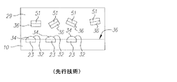
図1aは、先行技術のランダム配置方法の1つの種類の動作を、一般的に示す図である。図1aでは、基板10は、凹部21の形態の結合部位を有している。凹部21は、流体29内に浮遊するとともに対応した形状に形成されたマイクロ構成部品47を受け入れるような形状に形成されている。図1aに示すように流体29は、マイクロ構成部品47を含み、基板10に供給される。このとき、重力および/または他の力が、マイクロ構成部品47を基板10の上に、かつ、凹部21内に引き込む。これによって、大量および/または大規模な組立プロセスにより適した、大規模並列プロセスを使用するマイクロ構成部品47の基板10への組立が可能になる。
FIG. 1a is a diagram generally illustrating one type of operation of a prior art random placement method. In FIG. 1 a, the
マイクロ組立構造体を作るために、重力および/または剪断力に専ら依存することなしに、流体自己組立を使用するための別の手法が開発されてきた。これらのうちのいくつかを図1b〜1eに示す。図1b〜1eの各々には、結合部位22〜25を有した基板10が図示されている。結合部位22〜25は多数の形態を取ることができるが、それらのいくつかのみを図1b〜1eに例示している。
Other approaches have been developed to use fluid self-assembly to make micro-assembled structures without relying solely on gravity and / or shear forces. Some of these are shown in FIGS. In each of FIGS. 1b-1e, a
図1bには、マイクロ構成部品49を基板10上に配置する流体自己組立方法が図示されている。この組立方法は、基板10に設けられた結合部位22が、流体29内に浮遊するマイクロ構成部品49の上面である疎水性の表面48に係合された疎水性のパッチと結合することで実現されている。この型式の一例が、特許文献5に示され、かつ、説明されている。この特許文献5には、親水性または疎水性性質のうちの選択された1つを有する表面を基板上に作り出すように、表面処理流体に曝される基板が記載されている。この基板上には、スラリーが分配される。スラリーは、流体および複数のマイクロ構成部品を含む。2種類のマイクロ構成部品が供給される。この2種類のマイクロ構成部品のうち、1つは、協調設計されるとともに受容体部位を伴う親水性表面に付着するように設計されている。また、他の1つは、協調設計されるとともに受容体部位を伴う疎水性表面に付着するように設計される。スラリーが基板10上に分配されるとき、この二種類のマイクロ構成部品のうちの選択された1つのマイクロ構成部品の選択的親水性表面が、疎水性表面に付着せずに基板10上の親水性表面に付着する。親水性表面を有するマイクロ構成部品は、基板上の親水性パッチに係合する。したがって、マイクロ構成部品は、基板上の所定の場所に選択的に配置される。
In FIG. 1 b, a fluid self-assembly method is shown in which the
図1cには、別の流体自己組立方法が図示されている。図1cに示す方法は、自己組立のために毛細管力を使用する。図1cに示すように、結合部位23は、液体34の滴32と適応する。液体34とマイクロ構成部品51の表面36の間の毛細管吸引力が、流体29内に浮遊するマイクロ構成部品51を結合部位23上に組み立てるようにさせる。しかしながら、この方法は液体34の滴の基板10上への正確な配置を必要とし、多数の種類のマイクロ構成部品を有する構成部品の組立に有用な識別能を必ずしも提供しないことが理解されよう。この方法の様々な変型が一般的に非特許文献1に開示されている。
FIG. 1c illustrates another fluid self-assembly method. The method shown in FIG. 1c uses capillary forces for self-assembly. As shown in FIG. 1 c, the binding
図1dに示す先行技術では、結合部位24が流体29内に浮遊するマイクロ構成部品52上の磁気表面53を吸引する磁気パッチを含む、流体自己組立方法が示されている。そのような手法は、非特許文献2に開示されている。この非特許文献2は、よりニッケルドットのアレイによってパターン化される基板上に、微視的な金属ディスクを組み立てるための磁力の使用に関して詳細に記載されている。しかしながら、基板上に、ディスクのアレイを設けることは高コストとなりやすい。さらにそのような方法は、通常、組み立て対象であるマイクロ組立構造体それぞれが、磁力の使用を許容する磁気的特性を有する場合にのみ限定される。
In the prior art shown in FIG. 1 d, a fluid self-assembly method is shown in which the binding
マイクロ組立中のマイクロ構成部品の位置決めのために、静電吸引を使用することも提案されてきている。特許文献6および非特許文献3には、そのような方法が記載されている。図1eには、この静電的手法の一般的な例が図示されている。図1eに示すように、基板10は、流体29内に浮遊するとともに逆帯電されたマイクロ構成部品55を吸引する電極27と適応する結合部位25を有する。しかしながら、静電的に基づく流体マイクロ組立の使用は、誘電泳動によるマイクロ構成部品の長距離輸送に必要なアドレス可能な電極構造体を設けることが必要となり、コストが高くなる可能性がある。
It has also been proposed to use electrostatic attraction for positioning microcomponents during microassembly. Patent Document 6 and Non-Patent Document 3 describe such a method. A general example of this electrostatic approach is illustrated in FIG. 1e. As shown in FIG. 1e, the
上述したように、多くのマイクロ組立構造体は、様々な異なる種類のマイクロ構成部品を組み込んでいる。したがって、流体マイクロ組立などの大規模並列ランダム配置プロセスを使用して、2つ以上の種類のマイクロ構成部品を異種材料集積化することは極めて望ましい。したがって求められているものは、従来型の流体組立などのランダム配置方法であるが、決定論的方法の正確かつ選択的な組立能力を有する方法によって可能になる大量規模でマイクロ構成部品をマイクロ組立構造体内に組み立てる方法である。 As described above, many micro-assembly structures incorporate a variety of different types of micro-components. Thus, it is highly desirable to integrate two or more types of microcomponents into dissimilar materials using a large scale parallel random placement process such as fluid microassembly. What is needed, therefore, is a random placement method, such as conventional fluid assembly, but microassembly of microcomponents on a large scale is made possible by methods that have the precise and selective assembly capabilities of deterministic methods. It is a method of assembling in the structure.
上記で説明した流体自己組立方法のうちの少なくとも1つに対する変形が、この求めに合致させる試みで提案されてきている。例えば1つの手法では、基板上において異なる形に形成された受容体部位に係合するように、それぞれ異なる形に形成されたマイクロ構成部品を使用する従来型の流体組立技術が知られている。これは、基板が、マイクロ構成部品の特定の種類の形状に対応するべく、独特な形状に形成される結合部位を有することを要する。しかしながら、表面エッチング技術、マイクロ構成部品形成技術、コスト、電気的機能および配向の制約によって、識別用に使用できる形状構成の数は限られており、これが上述したプロセスを使用して基板上に配置でき得る異なる構成部品の数を限定する。 Variations to at least one of the fluid self-assembly methods described above have been proposed in an attempt to meet this need. For example, in one approach, conventional fluid assembly techniques are known that use differently shaped microcomponents to engage differently shaped receptor sites on a substrate. This requires that the substrate has a binding site that is formed in a unique shape to accommodate a particular type of shape of the microcomponent. However, due to surface etching technology, micro-component forming technology, cost, electrical function and orientation constraints, the number of features that can be used for identification is limited and this is placed on the substrate using the process described above. Limit the number of different components that can be made.
別の手法で、非特許文献4では、結合部位間を識別するために相補的なDNA分子または配位子間の結合の使用を論じている。この手法は高度の識別能をもたらすが、基板上にDNAまたは配位子をパターン化することで高コスト化する可能性がある。 In another approach, Non-Patent Document 4 discusses the use of binding between complementary DNA molecules or ligands to distinguish between binding sites. This approach provides a high degree of discrimination, but can be costly by patterning DNA or ligands on the substrate.
したがって、コスト効率のより向上でき得るマイクロ構成部品の大量異種材料組立のための方法が求められている。 Accordingly, there is a need for a method for mass dissimilar material assembly of microcomponents that can be more cost effective.
本発明の一態様では、結合部位のパターンを有する支持体上に構造体を組み立てる方法が提供される。本方法によれば、冷却に伴い粘性が増加するとともに結合部位に係合可能に構成された第1のマイクロ構成部品を含んだ第1の流体が、支持体の表面に供給される。第1の流体内に浮遊する第1のマイクロ構成部品の選択された結合部位への係合を妨げるために、選択された結合部位に近接する反応流体の粘性を増加させるべく、選択された結合部位に近接する第1の流体が冷却される。 In one aspect of the invention, a method of assembling a structure on a support having a pattern of binding sites is provided. According to the present method, the first fluid including the first micro component configured to increase in viscosity with cooling and engage with the coupling site is supplied to the surface of the support. The selected coupling to increase the viscosity of the reaction fluid proximate to the selected binding site to prevent engagement of the first microcomponent floating in the first fluid to the selected binding site. The first fluid proximate the site is cooled.
本発明の別の態様では、結合部位をその上に有する支持体上にマイクロ組立構造体を組み立てる装置が提供される。この装置は、結合部位と係合可能に構成された第1のマイクロ構成部品を含むとともに冷却に伴い粘性が増加する第1の流体を支持体上に適用する流体源と、マイクロ構成部品の選択された結合部位への係合を防止するために、選択された結合部位に近接する第1の流体の粘性が増加するべく、支持体が第1の流体を冷却するように、冷却された材料を支持体に適用する冷却付与器とを有する。 In another aspect of the invention, an apparatus for assembling a microassembly on a support having binding sites thereon is provided. The apparatus includes a first microcomponent configured to be engageable with the binding site and a fluid source for applying a first fluid on the support that increases in viscosity upon cooling and selection of the microcomponent. The cooled material so that the support cools the first fluid to increase the viscosity of the first fluid proximate to the selected binding site to prevent engagement to the selected binding site. And a cooling applicator for applying to the support.
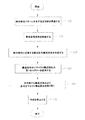
図2aは、本発明の方法の一実施形態のフローチャートである。図3aおよび3bは、図2aの方法による流体自己組立の一例を示す。図3aに示すように、支持体60が準備される(ステップ105)。支持体60としては、ポリエチレンテレフタレート、セルロースアセテート、ポリエチレン、ポリカーボネート、ポリメチルメタクリレート、ポリエチレンナフタレート、金属箔、布、織物、織られた繊維もしくはワイヤメッシュなどの柔軟性のある支持体またはガラスおよびシリコンなどの剛体の支持体など、さまざまなものを選択することができ、その材質等は特に限定されない。
FIG. 2a is a flow chart of one embodiment of the method of the present invention. Figures 3a and 3b show an example of fluid self-assembly by the method of Figure 2a. As shown in FIG. 3a, a
図3a〜3cに図示するように、支持体60は、結合部位62,64,66,68として機能する結合部位のパターンを有する。各結合部位62,64,66,68は、それぞれをマイクロ構成部品を受けるような形状に形成する等により、その上にマイクロ構成部品を組み立てることができるようになっている。別手法として、先行技術で開示されているような結合部位、例えば、形状合致、磁力、電気的力、疎水性吸引力、親水性吸引力、分子識別、および/または毛細管吸引力を使用してマイクロ構成部品と係合するように構成された結合部位62,64,66,68を支持体60に設けるようにしてもよい。
As shown in FIGS. 3 a-3 c, the
動作では、熱反応性流体72が支持体60に供給される(ステップ106)。図2および3a〜3bに示す実施形態では、これは支持体60を横断するように熱反応性流体72を流すことによって行われる。しかしながら、別の実施形態では、熱反応性流体72の浴内に支持体60を浸漬させる、などといった別の方法で、熱反応性流体72を支持体60に供給してもよい。
In operation, thermally
本明細書で使用されるとき、熱反応性流体という用語は、冷却に伴い粘性が増加する流体の意味で使用される。有用な熱反応性流体の例としては、冷却に伴い粘性が増加する高分子の水溶液、高分子電解質、高分子両性電解質(例えば、ゼラチン溶液)、ガム質、多糖類(例えば、ゼラチン、カラゲナン(carrageenan)、およびアガロース)またはそれらの組合せなどが挙げられるが、当然ながら、これらに限定されるものではない。これら任意の熱反応性流体の有用な範囲は、必要とされるゲル遷移温度を含む因子に依存し、それは高分子の濃度、イオン強度、イオンの種類、PH、ならびに高分子の分子重量および高分子の荷電群の分布に依存する。例えば、有用な熱反応性溶液には、120Kダルトンのゼラチン分子重量に対して、1〜20%ゼラチンの間のゼラチン水溶液が含まれる。 As used herein, the term thermally reactive fluid is used to mean a fluid that increases in viscosity with cooling. Examples of useful thermoreactive fluids include aqueous solutions of polymers that increase in viscosity upon cooling, polyelectrolytes, polyampholytes (eg, gelatin solutions), gums, polysaccharides (eg, gelatin, carrageenan ( carrageenan), and agarose) or combinations thereof, of course, but are not limited thereto. The useful range of these optional thermoreactive fluids depends on factors including the required gel transition temperature, which includes polymer concentration, ionic strength, ion type, pH, and polymer molecular weight and high Depends on the distribution of charged groups of molecules. For example, useful heat-reactive solutions include an aqueous gelatin solution between 1-20% gelatin per 120 K Dalton gelatin molecular weight.
熱反応性流体のさらに別の例には、0.1重量%以上の濃度のアガロース水溶液、0.4重量%以上の濃度のゼラチン水溶液が含まれる。これらの溶液のゲル遷移温度は約15℃である。さらに別の実施形態では、熱反応性流体は、冷却に伴いゲル化する熱反応性液体を形成するべくコロイドと相互作用する任意の高分子の溶液を含むことができる。例えば、この熱反応性流体は、ゼラチンと、例えば、WR Grace and Co., Davison Silica Products Division, East Chicago, IN, U.S.A.によって売られているLudox(登録商標)などのコロイダルシリカの混合物を含むことができる。 Yet another example of a thermally reactive fluid includes an agarose aqueous solution having a concentration of 0.1% by weight or higher and an aqueous gelatin solution having a concentration of 0.4% by weight or higher. The gel transition temperature of these solutions is about 15 ° C. In yet another embodiment, the thermoreactive fluid can comprise a solution of any polymer that interacts with the colloid to form a thermoreactive liquid that gels upon cooling. For example, the thermally responsive fluid may comprise a mixture of gelatin and a colloidal silica such as, for example, Ludox® sold by WR Grace and Co., Davison Silica Products Division, East Chicago, IN, USA. Can do.
さらに別の実施形態では、熱反応性流体は、3価の金属イオンを含むキサンタンガムの水溶液を含むことができる。例えば、アンドリューロッドによってProceedings of the 13th International Congress on Rheology, Cambridge, UK , 2000, Volume 4, pp. 389に記載されているように、アルミニウムイオンと結合した0.5重量%のキサンタンによって25〜75℃のゲル遷移温度が達成可能である。 In yet another embodiment, the thermally responsive fluid may comprise an aqueous solution of xanthan gum that includes trivalent metal ions. For example, as described by Andrew Rod in the Proceedings of the 13th International Congress on Rheology, Cambridge, UK, 2000, Volume 4, pp. 389, 25 to 75% by 0.5 wt% xanthan combined with aluminum ions. A gel transition temperature of 0 C can be achieved.
本明細書で説明される水溶液は、アルコールおよびポリエチレングリコールを含むことができる。非水溶液も使用することができる。例えば、塩素化溶剤および他の非水性溶剤を組み入れた熱反応性流体も供給することができる。 The aqueous solutions described herein can include alcohol and polyethylene glycol. Non-aqueous solutions can also be used. For example, a thermally reactive fluid incorporating a chlorinated solvent and other non-aqueous solvents can be provided.
適用では、熱反応性流体72は、実施形態図3aおよび3bにおいて結合部位62,66として図示される、支持体60上の選択された結合部位内かつ/またはその近くの領域で冷却される(ステップ107)。熱反応性流体72は、通常、間接的に冷却される。図3a〜3cには、熱反応性流体72の間接冷却の一例を示す。図3aに示す例では、冷却材料90が選択された結合部位62,66に近接する領域で支持体60に適用される。この冷却材料90の適用に反応して、支持体60のうち選択された結合部位62,66に近接する領域が冷却される。熱反応性流体72が支持体60の冷却された領域と接触するとき、熱反応性流体72の粘性が増加する。これにより熱反応性流体72内に遮蔽ゾーン92,94が形成される。遮蔽ゾーン92,94には、他の領域の熱反応性流体72よりも、高粘性の熱反応性流体72を有する。いくつかの実施形態の遮蔽ゾーン92,94は、第1の熱反応性流体72の流体の、ゼラチン状の、または固体形態を含むことができる。遮蔽ゾーン92,94は、マイクロ構成部品80が結合部位62,66と係合する能力を妨げる。
In application, the thermally
したがって、図3bに示すように、結合部位62,66に遮蔽ゾーン92,94が形成された後、支持体60に運搬流体73の第1のスラリー70および第1の種類のマイクロ構成部品80が適用される(ステップ108)。運搬流体73は、マイクロ構成部品80を支持体60に運搬することができ、かつ、流体自己組立に有用に適用される任意の流体を含むことができる。一実施形態では、運搬流体73は、熱反応性流体を含む。一実施形態では、熱反応性流体を適用するステップ(ステップ106)、遮蔽ゾーンを形成するべく熱反応性流体を冷却するステップ(ステップ107)、および、第1のスラリーを適用するステップ(ステップ108)は、第1のスラリーがステップ106で既に適用された熱反応性流体72内に第1のマイクロ構成部品80を導入することによって適用されるように統合することができる。しかしながら、これは必ずしも必要なく、運搬流体73は、熱反応性流体を含まなくてもよい。これは第1の流体72内に形成される遮蔽ゾーン92および94が、運搬流体73の適用中持続する場合行うことができる。
Thus, as shown in FIG. 3b, after the
マイクロ構成部品80は、オンシリコン集積回路、ナノワイヤ、ビーズ、ロッド、キューブ、ディスク、バッケイボール(buckey ball)、カプセル、電気泳動ビーズ、LED、発光材料、光反射材料、光吸収材料、導電性材料、磁性材料、絶縁材料、エアロゲル、生物学的細胞、DNAおよびDNA派生物、およびDNA鋳型構造体などを含むことができるが、当然、これらに限定されるものではない。マイクロ構成部品80は、熱反応性流体の溶液内に有効に浮遊可能な寸法であれば、任意の範囲の寸法にすることができる。この点に関しては、選択された実施形態では、マイクロ構成部品80は1ナノメートルと同じ程度に小さくしたり、数ミリメートルと同じ程度に大きく寸法設定することができる。
第1の種類のマイクロ構成部品80は、上述したように、当該技術分野で一般的に知られているように、結合部位62,64,66,68に係合するように構成されている。しかしながら、図3a〜3cの図示例では、第1の種類のマイクロ構成部品80は、結合部位62,66として図示される選択された結合部位に係合することは意図していない。したがって、遮蔽ゾーン92および94が、そのような係合を抑止する。特に、マイクロ構成部品80は、通常、それらが搬送流体73内で動き回るとき抵抗が最小となる通路を辿ることは理解されるであろう。したがって、マイクロ構成部品80が高粘性の遮蔽ゾーン92および94に到達した場合、マイクロ構成部品80は、遮蔽ゾーン92,94から離れて逸れる。その結果、マイクロ構成部品80は、結合部位62,66と係合しないことになる。その一方で、マイクロ構成部品80は、遮蔽ゾーン92,94によって保護されていない結合部位64,68と係合することができる。
The first type of
第1の種類のマイクロ構成部品80が、非選択部位64,68の各々に組み付けられた後、第1の搬送流体73および第1のマイクロ構成部品80のいかなる非係合部品も第1のマイクロ組み立てされた構造体100から取り除かれる(ステップ109)。これは例えば、機械的動作、真空または洗浄によって行うことができる。一実施形態では、支持体60上に残留し、かつ結合部位62,64,66,68のいずれとも結合しなかった第1の種類のマイクロ構成部品80も取り除くために、熱反応性流体72などの液体は支持体60から洗い流される。第1のスラリーの取り除き中、第1の種類の非係合マイクロ構成部品80が選択された部位62,66に結合することを防止するために、冷却材料90は結合部位62,66に近接する位置で支持体60に接触した状態のままとし、遮蔽ゾーン92,94が、適切な位置に残ったままとなるようにしている。第1のスラリー70の取り除きが完了した後、結合部位62,66に近接位置における支持体60の冷却を停止するために、この冷却材料90は、支持体から取り除かれる(ステップ110)。冷却材料90が支持体60から取り除かれると支持体60の温度は上昇する。その結果、局所的な温度低下に起因して形成される遮蔽ゾーン92,94も消滅する。第1のマイクロ組立構造体100は、第1の種類のマイクロ構成部品80と支持体60との結合の結果として形成される。この第1のマイクロ組立構造体100は、図2aの実施形態などのいくつかの実施形態では、最終のマイクロ組立構造体104を含むことができる。
After the first type of
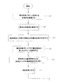
第1のマイクロ組立構造体100に対して追加のマイクロ構成部品を組み立てることもできる。図2Bおよび図3a〜3cは、支持体に2つ以上のマイクロ構成部品を組み立てるための方法の実施形態を示す。図2Bの実施形態は図2aの方法ステップを組み込み、かつ追加のステップ112〜122を加えている。図2Bの方法によれば、ステップ105〜110は上記で説明したように実施される。次に、以下で説明するように、中間マイクロ組立構造体102または最終マイクロ組立構造体104を形成するために支持体60の結合部位と係合するようになされた追加のマイクロ構成部品を供給することができる。そのような追加の構成部品は、第1の種類のマイクロ構成部品80、または図3cに示すように最終の種類のマイクロ構成部品84であることができる。
Additional microcomponents can also be assembled to the
最終マイクロ組立構造体104を作り出すのにさらなる組立ステップがただ1つしか必要でないと判定されるとき(ステップ112)、最終種類のマイクロ構成部品84を有する搬送流体73の最終スラリー76が第1のマイクロ組立構造体100に適用される(ステップ115)。これによって最終種類のマイクロ構成部品84が結合部位62,66に係合し、したがって、図3cに示すように最終マイクロ組立構造体104を形成することが可能になる。搬送流体73およびどのような最終マイクロ構成部品84も最終マイクロ組立構造体を作り出すために取り除かれる。任意選択として、熱反応性流体72を第1のマイクロ組立構造体100に適用し(ステップ113)、熱反応性流体72が遮蔽ゾーンを形成するように冷却されるように冷却材料90を適用することによって、第1のマイクロ組立構造体100を選択的に冷却することができる(図示せず)。そのような遮蔽ゾーンは、選択された結合部位が占有されないままにしておくために使用することができる。冷却材料90は取り除かれ、したがって、任意選択ステップ114で適用された冷却が次いで停止する(ステップ117)。
When it is determined that only one additional assembly step is required to create the final microassembly 104 (step 112), the
例えば、互いに異なる3種以上のマイクロ構成部品が支持体60に連結すべきである場合など、3以上のマイクロ組立ステップが実施されるべきであると判定されるとき(ステップ112)、図2Bに示す追加のステップ118〜122が実施される。図4は、これらの追加のステップが実施される図2Bの方法の動作を示す。 When it is determined that three or more microassembly steps should be performed (step 112), such as when three or more different microcomponents are to be coupled to the support 60 (step 112), FIG. The additional steps 118-122 shown are performed. FIG. 4 illustrates the operation of the method of FIG. 2B in which these additional steps are performed.
図4aおよび4bは、上記において図3a〜3bを参照して説明した場合と同様(ステップ105〜110)に、第1のマイクロ組立構造体100を形成するように支持体60に対する第1の種類のマイクロ構成部品80の組立を示す。図4cに示すように、熱反応性流体72は、マイクロ組立構造体100に供給され(ステップ118)、冷却材料90は少なくとも1つの遮蔽ゾーン98を形成するように支持体60に適用される(ステップ119)。図4dに示すように、次に、搬送流体73および中間の種類のマイクロ構成部品82を含む少なくとも1つの中間スラリー74が支持体60に供給される(ステップ120)。別の冷却材料96を、例えば、結合部位62に近接する少なくとも1つの別の遮蔽ゾーン98を形成させるべく中間スラリー74の熱反応性流体72に適用することができる(ステップ119)。結合部位62は遮蔽ゾーン98によって防護され、各結合部位66,68は既に第1の種類のマイクロ構成部品80と係合しているので、結合部位66のみが中間種類のマイクロ構成部品82との流体組立用に使用可能である。これによって中間マイクロ組立構造体102が形成される。次いで、中間スラリー84は支持体60から取り除かれ(ステップ121)、次いで、エネルギが取り除かれる(ステップ122)。次に、このプロセスは、中間マイクロ構成部品の追加の組立のために、または最終マイクロ構成部品84の組立のために戻る(ステップ113〜117)。
4a and 4b are similar to the case described above with reference to FIGS. 3a-3b (steps 105-110), the first type for the
ステップ111〜122は、必要なとき繰り返すことができる。この繰り返しにより、それ以前に形成されたマイクロ組立構造体に対する中間スラリー74(中間種類のマイクロ構成部品82を担持する搬送流体739の追加の適用が必要なマイクロ組立の多くのサイクルを行うことが可能になる。これらの任意の追加のステップで、支持体60または中間マイクロ組立構造体102は、必要なとき遮蔽ゾーンを形成するように冷却することができる。さらなる組立ステップが1つのみ実施されるべきであると判定されるとき(ステップ112)、図4eに示すような最終マイクロ組立構造体104を生じさせるようにステップ113〜117が実施される。
Steps 111-122 can be repeated as necessary. This repetition allows many cycles of microassembly that require additional application of intermediate slurry 74 (carrier fluid 739 carrying intermediate types of microcomponents 82) to previously formed microassembly structures. With these optional additional steps, the
本明細書において、第1の、中間の、および最終の種類のマイクロ構成部品は、同じ構造を備えることができ、かつ異種材料のマイクロ組立構造体の形成が可能なように必要なとき異なることができる。 As used herein, the first, intermediate, and final types of microcomponents can have the same structure and be different when necessary to allow the formation of microfabricated structures of dissimilar materials. Can do.
[支持体の冷却]
支持体60の冷却のステップ(ステップ107、114、および119)は、様々なやり方で実施することができる。上述したように、支持体60が熱反応性流体72を冷却できるように、支持体60または支持体60のいくつかの構成部品に冷却材料90を適用することによって、熱反応性流体72は、間接的に冷却される。冷却材料91は、典型的に、本明細書で説明する様々な実施形態でこの機能を果たすために使用される。特に以下で詳説するように、冷却部材91は、冷却材料90を支持体60に適用するために、冷却された構造体を移動させるパターン冷却器またはパターンローラを備えることができる。別の実施形態では、冷却部材91は、液体またはガスなどの流体の形態の冷却材料源、および、当該流体冷却材料91を支持体60に制御可能に供給するためのノズルを含むことができる。さらに別の実施形態では、冷却部材91は、支持体60の冷却器を作動させる選択的電気信号用の制御システムを備えることができる。
[Cooling of the support]
The step of cooling the support 60 (
いくつかの実施形態では、冷却材料90は、例えば冷却プレートまたは冷却材料90の他の表面を使用して支持体60に広く適用され、支持体60は選択的にこれに反応するようになされ、それによって選択的に熱反応性流体72を冷却する。別の実施形態では、冷却材料90は支持体60を選択的に冷却し、それによって熱反応性流体72を選択的に冷却するように選択的に適用される。
In some embodiments, the cooling
図5a〜5gは、結合部位62〜68として示される選択された結合部位に近接して支持体60と関連して配置される1組の冷却器132,134,136および/または138に支持体60が適応される、本発明の実施形態を示す。冷却器132,134,136,138は、支持体60を形成する材料と異なる熱反応特性を有する。冷却材料90が、広く支持体60に適用されるとき、冷却器132,134,136,138は、例えば、取り囲む材料60より強く冷却されることができ、あるいはより速い速度でなど有利な様式で、または支持体60の選択的冷却により可能であるよりも局所的な様式で、熱反応性流体60からエネルギを吸収するようになされることができる。
FIGS. 5a-5g support a set of
冷却器132,134,136,138は、任意の様々な形態を備えることができる。図5aに示す例では、冷却材料90は、結合部位62,66に近接して支持体60に適用され、冷却器132,136が冷却され、遮蔽ゾーン92,94を作り出すように結合部位62,66に近接する熱反応性流体72を冷却する。
The
図5bは、冷却器132,134,136,138の配列を有する支持体60の別の実施形態を示す。この実施形態では、冷却器132,134,136,138は、結合部位62,64,66,68の周りに、かつ近接して配置される。冷却材料90が、遮蔽ゾーン92,94の形成を達成するように、図4aに関して上述したように冷却器132,136に近接して支持体60に選択的に適用されるのが示されている。
FIG. 5 b shows another embodiment of a
図5cは、冷却器132,134,136,138の配列を有する支持体60の別の実施形態を示す。特に、図5cに示す実施形態では、結合部位62,64,66,68の各々は、対応する冷却器132,134,136,138を有する。各冷却器132,134,136,138は、支持体60のうち結合部位62,64,66,68の底部に相当する部分に配置されている。この実施形態によれば、支持体60が、近接する冷却器132,134,136,138によって冷却されるとき、結合部位60,62,64,66内のどのような熱反応性流体72も冷却される。これにより、結合部位内の熱反応性流体72の粘性が増加し、例えば、マイクロ構成部品80の結合部位62,66への組み付けを防止する遮蔽ゾーン92,94が形成される。
FIG. 5 c shows another embodiment of a
図5dは、冷却器132,134,136の配列を有する支持体60のさらに別の実施形態を示す。この実施形態では、支持体60は、結合部位62,64,66の配列を有するが、各結合部位62,64,66は、マイクロ構成部品80の液体係合表面88と係合するように構成された液体140を有する。冷却器132,134,136は、結合部位62,64,66に近接して支持体60上に配置される。結合部位62に近接した冷却器132が冷却されて支持体60が冷却されると、これにより冷却器132に近接する支持体60が、流体140を冷却する。流体140は同様に、マイクロ構成部品80が液体140と係合するのを防止する遮蔽ゾーン92を形成するように第1の熱反応性流体72を冷却する。
FIG. 5 d shows yet another embodiment of the
図5eは支持体60に設けられた各結合部位62,64,66が、マイクロ構成部品80の液体係合表面88と係合するための液体140を有する、別の実施形態を示す。図5eに示すようにこの実施形態では、冷却器132,134,136は、結合部位62,64,66の近傍周囲において、当該結合部位62,64,66に直接接触して配置されており、液体140を直接冷却する。
FIG. 5 e shows another embodiment in which each
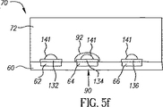
支持体60に設けられた各結合部位62,64,66が、第1のマイクロ構成部品80の液体係合表面88と係合するように設けられる液体140を有する、さらに別の実施形態を図5fに示す。図5fに示すように、冷却器132,134,136は、それぞれ、結合部位62,64,66に配置され、液体140と直接接触または近接して存在する。この実施形態では、冷却器132,134,136のうちのいずれかが冷やされると、液体140が上述したように遮蔽ゾーン92を形成するべく冷却される。
Yet another embodiment is shown in which each
図5d、5eまたは5fのいずれにおいても、少なくとも部分的な液体140の冷却に基づいて遮蔽ゾーンが形成されるように、冷却器は液体140を冷却することができる。図5gに示すさらに別の実施形態では、液体141の堆積が冷却器として機能する。これは、熱反応性流体72の導入前に、冷却、または、過冷されている。あるいは、支持体60または熱反応性流体72に適用されるとき冷却効果をもたらすように反応する液体141のパターンを適用することによって行うことができる。そのような実施形態では、流体141は冷却材料90を含んで使用することができる。
In any of FIGS. 5 d, 5 e or 5 f, the cooler can cool the liquid 140 such that a shielding zone is formed based on at least partial cooling of the liquid 140. In yet another embodiment shown in FIG. 5g, the deposition of liquid 141 functions as a cooler. This is cooled or supercooled prior to introduction of the thermally
アセトンまたは塩化メチレンなどの冷却液141を支持体60の表面にパターンのように適用することができることは理解されるであろう。
It will be appreciated that a
冷却材料90は、液体またはガス状の形態などの流体の形態で支持体60に同様に適用することができる。例えば、液体冷却材料90は、支持体60に均一に適用することができ、または特に印刷、ドロップオンデマンドのインクジェット技術、マスキング、連続インクジェット技術、または冷却材料90などの材料を供給するための溶剤として超臨界冷却二酸化炭素を使用する印刷技術を使用して、パターン化された様式で適用することができる。
The cooling
冷却材料90は、熱反応性流体72が導入される前に支持体60に適用することができる。このように適用されるとき冷却材料90は、支持体60上に結合部位を有する支持体60の側面に直接適用できる。あるいは、冷却材料90は、反対側に適用することができる。冷却材料90が、熱反応性流体72の導入前に支持体60に適用される場合、遮蔽ゾーンによって保護されるべき如何なる結合部位も、冷却する冷却材料90、支持体60および/または冷却器132や134などの冷却器を設けることができる。これは、マイクロ構成部品を有するスラリー70が支持体60に適用される間に、遮蔽ゾーンが消失することを確実に防止する。冷却器132および134は、制御される冷却反応に特に適応させることができる。
The cooling
図5H〜5Lは、支持体60への均一な冷却材料の適用に対して異なる熱反応を有する冷却器132、134、および136を備えた結合部位62、64、66および68と、支持体60と、が適応する実施形態を示す。
FIGS. 5H-5L
図5H〜5Lでは、この熱反応の相違は、支持体60上の選択された結合部位62、64、66および68における、選択的なマイクロ組立を可能にするために使用される。特に、この効率の相違に起因して、同一量のエネルギを適用したとしても、冷却器132、134、および136のうちの一つの冷却器は遮蔽ゾーン形成に必要な温度に到達するが、他の冷却器は十分な速度で放熱できないため遮蔽ゾーン形成に必要な温度に到達できない。後に詳説するように、スキャニングシステムやマスク処理などによって部分的な冷却を行わなくても、冷却器132、134、および136の特性を制御するようにすれば、いずれの結合部位を充填状態にし、いずれの結合部位を空のままにするか、換言すれば、いずれの結合部位に遮蔽ゾーンを形成するかを、選択することが可能になる。そして、結果として、識別能をもたらしつつ、全ての結合部位に均一なエネルギ供給が可能になる。
In FIGS. 5H-5L, this thermal reaction difference is used to allow selective microassembly at selected
図5H、5Iおよび5Jは、どのようにこれが行われるかを示す。図5H、5Iおよび5Jにおいて、冷却材料90の適用によって冷却されて、同じ量の冷却に曝されるとき、冷却器134は、冷却器132および136とは異なる熱反応性を発揮する。図5Hは、支持体60上に配列された冷却器132、134、および136有する組立プロセスの第1のステップを示す。図5Hに示すように、第1のマイクロ構成部品80を含んだ熱反応性流体72の第1のスラリー70に、支持体60を曝す前、または、または曝している間に、支持体60は、支持体60の結合部位62、64、66および68に近接して均一に冷却される。この冷却は、支持体60のある領域からのエネルギ流出の時間的速度として測定することができる。そして、この冷却は、効率の悪い冷却器132および136が遮蔽ゾーン92および96を形成し、かつ、冷却効率の良い冷却器134も遮蔽ゾーン94を形成するように、確立される。したがって、第1の種類のマイクロ構成部品80は、冷却器のない結合部位66にのみ係合する。
Figures 5H, 5I and 5J show how this is done. In FIGS. 5H, 5I and 5J, the cooler 134 exhibits a different thermal reactivity than the
図5Iは第2の組立ステップを示す。この組立ステップでは、支持体60は、より効率の良い冷却器134が遮蔽ゾーン96を形成するのに適切であるが、より効率の悪い冷却器132および136が遮蔽ゾーンを形成するのに不適切である第2の冷却材料190に曝される。したがって、第2のまたは中間のマイクロ構成部品82を含む中間スラリー74を導入すれば、より効率の悪い冷却器132および136に対応する結合部位62および68に中間種類のマイクロ構成部品82が係合することができる。
FIG. 5I shows the second assembly step. In this assembly step, the
図5Jは、最終組立ステップなどのさらに別の組立ステップを示す。このステップでは、より効率的な冷却器134が遮蔽ゾーンを形成するのに低すぎないエネルギに、支持体60を暴露する。これにより、最終種類のマイクロ構成部品84を搬送流体76内に含む最終スラリーが、これらのより効率の良い冷却器134に対応する結合部位64に付着するのを可能にする。
FIG. 5J shows yet another assembly step, such as a final assembly step. In this step, the
本発明のいくつかの実施形態では、第2の冷却材料を導入することは必要ではない。そして、そのような実施形態では、第1のスラリー70の流れの時間は、最初の冷却量で、結合部位62、64、および66に遮蔽ゾーン92、94、および98が形成されるのに必要十分な時間内に設定される。一方、第2のスラリー74の導入は、より効率の悪い冷却器132および136を介して供給された冷却が遮蔽ゾーン92および98が消散できる程度まで十分に低減した後、かつ、より効率の良い冷却器134を介して供給される冷却が遮蔽ゾーン94が消散する程度に低減される前の時間に起きるように、その導入時間が決められる。同様に、この実施形態では、より効率的な冷却器134によって供給された冷却が遮蔽ゾーン94が消散できるのに十分に減らされた後に最終スラリーを導入することができる。
In some embodiments of the present invention, it is not necessary to introduce a second cooling material. And in such an embodiment, the time of flow of the
結合部位に異なる熱吸収特性または異なる熱放出特性を有する少なくとも2種類の冷却器を作ることによって、識別能を結合部位に与えることができる。 By making at least two types of coolers with different heat absorption or different heat release characteristics at the binding site, discriminating ability can be imparted to the binding site.
図5K〜5Mは、均一冷却に異なるやり方で対応する冷却器132、134、136および138の配列を有する支持体60の別の実施形態を示す。この実施形態では、冷却器132、134、および136は支持体に適用されるとき共通の熱反応および共通の厚さを有する共通の材料から形成される支持体60上に設けることができるが、それでも識別能を提供することができる。これは冷却器の製造およびそれらの支持体60への取り付け位置の制御を簡単化する。
5K-5M illustrate another embodiment of a
具体的には、この実施形態では、冷却器134が供給できる熱冷却を選択的に制御するように、冷却器132および136と比べて異なる寸法を有する冷却器の配置を使用することによって識別能が達成される。これは遮蔽ゾーンを生じさせるためにスラリー内の反応流体72に熱的に供給できる冷却速度および/または冷却量を制限する。冷却器132、134、および136によって冷却される領域のスラリーの冷却器区域内への空間的分布が、各冷却器132、134、および136を取り囲む冷却された温度領域のプロファイルを決める。十分な暴露90によって冷却器132、134、および136に冷却器132、134、および136の横方向範囲を超える遮蔽を生じさせることができる。
Specifically, in this embodiment, discrimination capability is achieved by using a cooler arrangement having different dimensions compared to
図5K〜5Mは、冷却器のこの配置の一実施形態を示す。図5K〜5Mに示す実施形態では、結合部位62および68の底部表面の実質的に全てをカバーする冷却器132,136が示され、他方冷却器134は冷却器132および136のわずかな横方向範囲のみカバーしている。結合部位66は冷却器を全く有していない。図5Lに示す支持体60を使用する組立プロセスの第1のステップでは、より小さな冷却器134がその対応する結合部位64が第1のスラリー70の導入に際して第1の種類のマイクロ構成部品80が付着することから保護するのに適当な範囲の遮蔽ゾーン94を生じさせるのに十分なエネルギ90の第1の均一な暴露がもたらされ、一方、より広い冷却器132および136は関連する結合部位62および68を保護するための遮蔽ゾーン92および96を形成し、したがって、冷却器のない結合部位66のみが第1のマイクロ構成部品80によって充填される。
Figures 5K-5M illustrate one embodiment of this arrangement of coolers. In the embodiment shown in FIGS. 5K-5M,
図5Lは、より広い冷却器132および136が中間遮蔽ゾーン98を形成するのに適当な冷却材料90に対する第2の、より低い暴露を有し、かつそれに曝された第2の種類のマイクロ構成部品82をその中に有する第2のスラリー74に曝された図5Kの支持体60を示す。しかしながら、横方向により小さなエネルギ吸収冷却器134は十分な冷却をもたらさず、遮蔽ゾーンに結合部位64に中間種類のマイクロ構成部品84が接着するのを防止するのに小さすぎる遮蔽ゾーンしか形成しないまたは形成できないので、したがって、横方向により小さな冷却器134を伴う各部位は、第2のスラリー74の導入に際して中間種類のマイクロ構成部品84によって充填される。
FIG. 5L shows a second type of micro-configuration in which the
図5Mは、支持体60がエネルギに曝されていない、またはどのような冷却器も遮蔽ゾーンを作り出すのに不十分なレベルのエネルギ(図示せず)にしか曝されていないときの、支持体60に適用される最終マイクロ構成部品84を有する最終スラリー76の適用を示す。これによって、最も広い冷却器132および136を伴う各結合部位62および68が、最終スラリー76の導入に際して最終マイクロ構成部品86を受けることが可能になる。
FIG. 5M shows the support when the
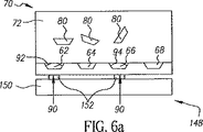
図6a〜6dは、エネルギが熱反応性流体72の局所的冷却を生じさせるように選択的に適用される本発明の様々な別の実施形態を示す。図6aに示すように、支持体60に結合部位62、64、66および68が設けられる。この実施形態では、支持体60は、突起部152を有するパターン化された冷却ブロック150を備える接触冷却器148を使用してなど、固体形態の冷却材料を選択された結合部位62および66に近接して支持体60と接触して適用することによって冷却される。パターン化される冷却ブロック150の突起部152は、上記で説明したように遮蔽ゾーン92および94の形成を可能にするように結合部位62および66に近接して支持体60を選択的に冷却する。
FIGS. 6 a-6 d show various alternative embodiments of the invention in which energy is selectively applied to cause localized cooling of the thermally
図6bは、各々が液体140を伴う結合部位62、64、および66を有する支持体60を冷却するために、突起部152を有するパターン化された冷却ブロック150を備える接触冷却器148を使用する選択的結合部位62の冷却を示す。
FIG. 6 b uses a contact cooler 148 comprising a patterned
そのような接触冷却器148は多くの形態を取ることができることは理解されるであろう。例えば、図6aおよび6bに示す種類の冷却ブロック150は、支持体60と接触し、固定されたパターンの突起部152を使用して支持体60を冷却するようになされた隆起する領域の形態の突起部152を有する圧盤、ロール、または他の冷却表面の形態を取る。
It will be appreciated that such a contact cooler 148 can take many forms. For example, a
図6cは、支持体60と接触し、結合部位62および66と近接する突起部152を有する冷却ブロック150の異なる実施形態を示す。この実施形態では、突起部152は選択可能にアドレス可能な、要求に応じて突起部152を支持体60と接触させかつ接触を解くアクチュエータ154を有する。このようにすると、多数の組立サイクル中、支持体60はブロック150および支持体60のどちらも移動させることなく動的に調整されるパターンで冷却することができる。図示のこの実施形態では、突起部152は、要求に応じて突起部152を支持体60と選択的に接触させまたは接触を解くことができる電気的に作動可能なマイクロモータまたは圧電アクチュエータなどの選択的にアドレス可能なアクチュエータを有する。
FIG. 6 c shows a different embodiment of the
図6dは、突起部152を有する冷却ブロック150を使用する選択的部位の冷却を示す。この実施形態では、突起部152は、支持体60上の冷却領域のパターンの動的調整を可能にするように、選択的に作動可能な冷却器156を組み込むようになされている。
FIG. 6 d shows selective site cooling using a
図7は、冷却を選択的に支持体60に適用し、かつそれによって上記で説明したように選択的な組立ができるように遮蔽ゾーンの形成を可能にするように熱反応性流体72に適用することができる、構造体を組み立てるための装置158の一実施形態を示す。図7は、大量生産に適した巻取りウエブベースの連続製造プロセスの使用も示す。この実施形態では、供給部160がその上に結合部位の配列(図示せず)を有する支持体60の連続ウエブを供給する。支持体60のこのウエブは、第1のローラ162を通過する。第1のローラ162は熱伝達ローラであり、接触するときに支持体60の選択された領域の冷却が可能である。この点に関して、第1のローラ162は、第1のローラ162に冷却された領域の所望のパターンを供給することができるペルチェ型式の冷却器または他の冷却源などの第1のパターン冷却器164によって選択的に冷却されるようになされている。動作では、第1のパターン冷却器164は、第1のローラ162が回転するとき、エネルギ90aのパターンを第1のローラ162に供給する。支持体60のウエブが第1のローラ162と係合するとき、冷却90の対応するパターンが第1のローラ162から支持体60のウエブに伝達される。
FIG. 7 applies cooling to the heat-
支持体60が冷却された後、支持体60は第1の浴165を通過する。第1の浴165は熱反応性流体72を収容する。熱反応性流体72が支持体60によって冷却されるとき、上記で説明したように遮蔽ゾーンが形成される。遮蔽ゾーンによって特定の部位が封鎖された支持体60が第1のスラリー浴166を通過する。別法として、支持体60は上記で説明したように、第1の浴165を通過するときに冷却することもできる。
After the
第1のスラリー浴166は、熱反応性流体72などの搬送流体73内に第1のマイクロ構成部品80などのマイクロ構成部品を有する第1のスラリー70を収容する。この遮蔽ゾーンは、第1のマイクロ構成部品80が選択された結合部位に係合するのを防止する。マイクロ構成部品80は、マイクロ組立構造体100を形成するように、遮蔽ゾーンによって保護されない結合部位に係合する。支持体60が図7に示すシステム158の通過を継続するとき、支持体60は、支持体60から第1のスラリー70の残留量を取り除く洗浄デバイス168を通過する。
The
支持体60のウエブは、次いで少なくとも1つの中間ローラ170上を通る。図示の実施形態では、中間ローラ170は中間パターン冷却器172から冷却されたパターン領域90aを受け取り、選択的に支持体60のウエブを冷却するようになされた別の熱伝達ローラを備える。支持体60が冷却された後、支持体60は中間スラリー浴174を通過する。中間スラリー浴174は、この実施形態では中間種類のマイクロ構成部品82を含む熱反応性流体72を備える搬送流体73を有する。中間マイクロ構成部品84は次いで、中間のマイクロ組立構造体102を形成するように、マイクロ組立構造体100の結合部位に係合することができる。中間スラリー浴174に使用される熱反応性流体72の種類は、第1のスラリー浴166で使用される搬送流体で使用される熱反応性流体の種類と同じであることも、または異なることもできる。
The web of
熱反応性流体72が支持体60によって冷却されるとき、上記で説明したように遮蔽ゾーンが形成される。これらの遮蔽ゾーンは中間マイクロ構成部品84が選択された結合部位に係合するのを防止する。マイクロ構成部品84は、マイクロ組立構造体100を形成するように、遮蔽ゾーンによって保護されない結合部位に係合する。支持体60が図7に示すシステム158の通過を継続するとき、支持体60は、支持体60から中間のスラリーの残留量を取り除く中間洗浄デバイス176を通過する。
When the thermally
支持体60のウエブは次いで、最終のローラ180の上を通る。図示の実施形態では、最終ローラ180は、最終パターン冷却器182から冷却されたパターン領域90aを受け取り、選択的に支持体60のウエブを冷却するようになされた別の熱伝達ローラを備える。支持体60が最終ローラ180によって冷却された後、支持体60のウエブは最終スラリー浴184を通過する。最終スラリー浴184は、熱反応性流体72などの搬送流体73内に少なくとも1つの最終種類のマイクロ構成部品86を含む。しかしながら、最終スラリー浴184で使用することができる熱反応性流体72は、第1のスラリー浴166または第2のスラリー浴174で使用される搬送流体と同じであることもまたは異なることもできることは理解されるであろう。
The web of
熱反応性流体72が支持体60によって冷却されるとき、上記で説明したように遮蔽ゾーンが形成される。これらの遮蔽ゾーンは最終種類のマイクロ構成部品86が選択された結合部位に係合するのを防止する。マイクロ構成部品84は、最終マイクロ組立構造体104を形成するように、遮蔽ゾーンによって保護されていない結合部位に係合する。支持体60が図7に示すシステム158を通る移動を継続するとき、支持体60は、最終マイクロ組立構造体104から最終スラリーの残留量を取り除く最終洗浄デバイス186を通過する。支持体60および最終マイクロ組立構造体104は次いで、組立後処理ステーション220へ移動し、そこで支持体60およびマイクロ組立構造体104は、例えば、支持体60をマイクロ組立構造体104から分離することによって、あるいはそうではなく最終マイクロ組立構造体104を包装しまたは処理することによって、使用のためにさらに処理される。
When the thermally
エネルギのパターンが支持体60に伝達された後、それらは周囲物体によって加熱されるので有限の寿命を有する「クールスポット(cool spot)」が支持体60上に形成されることは理解されるであろう。クールスポットは、主としてクールスポットと熱反応性流体72を含む周囲物体との温度差によって決まる速度で加熱される。クールスポットの寿命を延長するために、遮蔽ゾーン92を形成するために要求される冷却量を最小限にし、他方同時に、冷却スポットとその周囲物体間の温度差を減少させるように、熱反応性流体72を、熱反応性搬送流体72が液体からゲルに遷移する遷移温度などの、熱反応性搬送流体72の粘性が著しい変化を行うまたは粘性の遷移を行う遷移温度よりわずかに高い温度で供給することが有利な場合がある。
It will be appreciated that after energy patterns are transferred to the
支持体上の選択された結合部位に対応する遮蔽ゾーンを形成するために選択的に支持体60を冷却する別の実施形態を図8A〜8Bに示す。図8Aに示すように、この実施形態では、熱伝達ローラ162、170および180を含まない連続プロセスが提供される。その代わりにこの実施形態では、第1のパターン冷却器164、中間パターン冷却器172、および最終パターン冷却器182が直接支持体を冷却するようになされている。図8Aにも示すように、この実施形態では、中間スラリーに含まれる熱反応性流体72が所望の遮蔽ゾーンを形成できるように、中間パターン冷却器172が支持体60を直接冷却するのが示されている。
Another embodiment for selectively cooling the
別法として、パターン冷却器164、172または182のいずれかが、電気的にアドレス可能な冷却要素のアレイを備えることもできる。例えば、本発明の方法で使用するための電気的にアドレス可能な冷却要素の典型的なアレイには、電気エネルギをジュール効果を介して冷却効果に変換する、複数の隣接する微小なペルチェ型式の冷却要素が含まれる。そのような熱ヘッドは、支持体60が、第1のローラ162、中間ローラ170、または最終ローラ180などの熱伝達ローラを横切って移動するとき、支持体60をパターン化された様式で冷却するために熱を支持体60から伝達することができるように支持体60と接触して、またはそれに極めて近接して使用することができる。
Alternatively, either pattern cooler 164, 172 or 182 can comprise an array of electrically addressable cooling elements. For example, a typical array of electrically addressable cooling elements for use in the method of the present invention includes a plurality of adjacent micro Peltier types that convert electrical energy into a cooling effect via the Joule effect. A cooling element is included. Such a thermal head cools the
図8Bは、支持体60を直接的に冷却するようになされたローラ191を備える第1のパターン冷却器164などのパターン冷却器の一実施形態を示す。図8Bに示すようにこの実施形態では、ローラ191の表面195近くに配置されるペルチェ型式の冷却要素などの選択的にアドレス可能な冷却器193aおよび193bのパターンによってローラ191が適応されている。ローラ191の表面155は、支持体60が第1の流体浴165を通過する前にまたは通過するときに支持体60と接触する。図示の実施形態では、冷却器193aは活性であり支持体60の冷却を行っており、一方冷却器193bは、インタラクティブであり支持体60を冷却しない。したがって、支持体60が第1の流体浴165内に移動するとき、上記で説明したように冷却された支持体60の第1の流体浴165内の領域の熱反応性流体72は遮蔽ゾーンを形成し、一方、他の領域では遮蔽ゾーンは形成されない。
FIG. 8B shows one embodiment of a pattern cooler, such as a first pattern cooler 164 that includes a
さらに別の実施形態では、ペルチェ型式の冷却器のアレイまたは別の冷却器のアレイなどの、支持体60によって使用される通路を横切って配設される直線アレイの冷却要素を備える任意のパターン冷却器164、172および182を移動の通路を横切って設けることができる。図7および図8A〜8Bに関して説明した方法は、非連続プロセスでも実施できることは理解されるであろう。例えば、図9に示すように、支持体60の区画の個々のシートは、システム158を順次または非順次プロセスで通過する圧盤190上に設けることができる。圧盤190は、支持体60をマイクロ組立中保持しかつ位置決めすることができる任意の剛体のまたは柔軟性のある構造体を備えることができる。圧盤190は、コンベアシステムによって移動させることができ、あるいは自己推進および/または自己案内することもできる。図示の実施形態では、上面192、194および196をそれぞれ直接冷却するパターン冷却器によって支持体60、マイクロ組立構造体100、および少なくとも1つの中間マイクロ組立構造体102にエネルギを加えることができる。
In yet another embodiment, any pattern cooling comprising a linear array of cooling elements disposed across the passage used by the
しかしながら図10に示す別の実施形態では、裏面198、200または202をそれぞれ冷却し、それらが次いで熱反応性流体に曝されるとき遮蔽ゾーンの選択された配列を形成できるように、上記で説明したように遮蔽ゾーンを形成するように熱反応性流体を冷却するために、支持体60、マイクロ組立構造体100、および少なくとも1つの中間マイクロ組立構造体102に異なる量の冷却を加えるパターン化された接触冷却器206を圧盤190に適用することができる。
However, in another embodiment shown in FIG. 10, as described above, the back surfaces 198, 200, or 202 can be cooled, respectively, to form a selected array of shielding zones when they are then exposed to a thermally reactive fluid. In order to cool the thermally responsive fluid so as to form a shielding zone as described above, the
別の実施形態では、支持体60の個々のシートは、圧盤190なしでマイクロ組立構造体を形成するために、装置158の任意の上記で説明した実施形態を通過させることができる。例えば個々のシートは、ベルトドラムまたは他の搬送システムを限定ではなく含む任意の知られたコンベアシステムを使用して装置158を通過させることができる。
In another embodiment, individual sheets of
図11A〜11Hは、この実施形態では赤、緑および青色の電気泳動ビーズまたは2色(bichromic)ビーズの組合せを備えるカラー表示要素を有するカラー表示器を形成するための装置158の一実施形態の用途を示す。図11Aは、マイクロ組立プロセスを通る支持体60の移動を示し、一方図11Bは、支持体60およびマイクロ構成部品80〜84の組立前の支持体60の断面212のトップダウン図を示す。図11Cは、第1の処理ステップ後の支持体60の断面212のトップダウン図を示す。
FIGS. 11A-11H illustrate one embodiment of an
図11Aを参照すると、組立プロセスの第1のステップでは、支持体60は熱反応性流体を収容する第1の流体浴165を通過する。パターン冷却器(図示せず)が緑のマイクロカップ部位216、青のマイクロカップ部位218の各々に近接してエネルギのパターンを加える。図11Cを見れば分かるように、これが緑のマイクロカップ部位216および青のマイクロカップ部位218に近接する遮蔽ゾーン92および94のパターンの形成を生じさせる。
Referring to FIG. 11A, in the first step of the assembly process, the
第1のスラリー浴166が、赤のマイクロビーズ230を有する搬送流体73の第1のスラリー70を支持体60に適用する。第1のスラリー166が適用されるとき、赤のマイクロビーズ230は赤のマイクロカップ部位214に結合する。図11Dは、マイクロカップ部位214の各々を充填する赤のマイクロビーズ230のアレイを有する完成した第1のマイクロ組立構造体100の上面図を示す。
A
このようにして第1のマイクロ組立構造体100が形成される。マイクロ組立構造体100は次いで、どのような残留未結合の赤のマイクロビーズ230も取り除くために洗浄機168内で洗浄される。遮蔽ゾーン92および94を形成することができたエネルギは次いで、続いて別の遮蔽ゾーンが第1のマイクロ組立構造体100に適用できるように取り除かれ、または消散させることができる。
In this way, the first
図示の実施形態では、第1のマイクロ組立構造体100から赤のマイクロビーズ230が取り除かれた後、冷却領域の新たなパターンが第1のマイクロ組立構造体100に形成され、第1のマイクロ組立構造体100は、この実施形態では熱反応性流体72内に緑のマイクロビーズ232を含む中間マイクロ構成部品を有する中間スラリー浴174内に曝され、図11Dに示すように青のマイクロカップ部位218に近接して中間の遮蔽ゾーン96の形成を生じさせる。
In the illustrated embodiment, after the
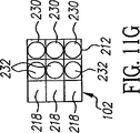
緑のマイクロビーズ232は、赤のマイクロカップ部位214が赤のマイクロビーズ230によって占有されているため赤のマイクロカップ部位214に係合することが妨げられ、かつ青のマイクロカップ部位218が遮蔽ゾーン96によって遮蔽されているので青のマイクロカップ部位218に係合することからも妨げられる。したがって、図11E、11Fおよび11Gに示すように、中間スラリー74が第1のマイクロ組立構造体100および遮蔽ゾーン96に適用されている間、緑のマイクロビーズ232は支持体60上に緑のマイクロビーズのパターンを形成するように緑のマイクロビーズカップ部位216に係合し、中間マイクロ組立構造体を生み出す。
図11Gにも示すように、組立の後中間マイクロ組立構造体102は次いで、どのような未結合の緑のマイクロビーズ232も取り除くために中間洗浄機176によって洗浄される。洗浄中この中間遮蔽ゾーン96は、洗浄中未結合の緑のマイクロビーズ232が青のマイクロカップ部位218に係合しないように保存される。支持体60上に形成される冷却領域のパターンは、結合部位の青のマイクロカップ部位218が青のマイクロビーズ234を受けることができるように遮蔽ゾーン96が消滅できるように、取り除かれまたは消散するままにされる。最終スラリー浴184が青のマイクロビーズ234および搬送流体73を有する最終スラリー76を中間マイクロ組立構造体102に適用する。青のマイクロビーズ234は、赤のマイクロカップ部位212、および緑のマイクロカップ部位214に係合することが、それらがそれぞれ赤のマイクロビーズ230、および緑のマイクロビーズ232によって占有されているので阻止される。したがって、図11Hに示すように、青のマイクロビーズ234のパターンは、支持体60に青のマイクロビーズ234のパターンを形成するように、残っている占有されていないマイクロカップ部位、青のマイクロカップ部位218に係合し、この結果最終のマイクロ組立構造体104が形成される。最終マイクロ組立構造体104は次いで、どのような残留未結合の青のマイクロビーズ234も取り除くために洗浄され、次いで乾燥、結合、積層、または集積表示器構成部品として満足に使用するための最終マイクロ組立構造体を組み立てるなどのステップを含むことができる後処理220に供される。
As also shown in FIG. 11G, after assembly, the
本発明のどのような実施形態においても、マイクロ構成部品が結合部位に係合するように配置されるであろう大きなリスクが存在するものの、冷却が遮蔽ゾーンの形成を可能にするであろう状況下で行われる限り、熱反応性流体の冷却を組立プロセスの前もしくはその最中、および/または洗浄プロセスの前もしくはその最中の任意のときに実施できる。したがって例えば、熱反応性流体72および第1の種類のマイクロ構成部品80を含む搬送流体73を有する第1のスラリー70が適用される図12の実施形態では、熱反応性流体を支持体に適用するステップ(ステップ105)は省略することができる。これは、この実施形態では、支持体60は第1のスラリー70が適用される(ステップ108)の前に支持体60が選択的に冷却される(ステップ107)からである。これによって第1のマイクロ構成部品80が選択された結合部位に結合する大きなリスクが存在する前に遮蔽ゾーンを形成することができる。このようにすると、中間組立および最終プロセスを短縮できるように、ステップ113および118もステップ115および120にそれぞれ統合することができる。
In any embodiment of the invention, there will be a significant risk that the micro-component will be positioned to engage the binding site, but the cooling will allow the formation of a shielding zone As long as it is performed below, cooling of the heat-reactive fluid can be performed before or during the assembly process and / or at any time before or during the cleaning process. Thus, for example, in the embodiment of FIG. 12 where a
上記で示した様々な図で、遮蔽ゾーン92、94および96は例示の目的で定義される形状を有して示されてきたが、これらの形状は限定ではない。遮蔽ゾーンは、マイクロ構成部品の選択された結合部位への結合に対する、そのような結合を防止するのに最小源の抵抗さえもたらせば十分である。例えば、いくつかの実施形態では、結合部位の部分的な封鎖で十分である可能性がある。配位子または他の生物学的な結合部位が使用される別の例では、配位子の受容部位を単に封鎖またはマスクすることで十分である可能性がある。
In the various figures shown above, shielding
さらに、上記で示した実施形態で、遮蔽ゾーンはそこに結合されたマイクロ構成部品を有さない開いた結合部位用にのみ提供されるとして示されてきている。これも限定ではなく、本発明はマイクロ構成部品によって占有される結合部位に近接する遮蔽ゾーンの形成を可能にするように実施することができる。 Furthermore, in the embodiment shown above, the shielding zone has been shown to be provided only for open binding sites that do not have microcomponents coupled thereto. Again, this is not a limitation and the present invention can be implemented to allow the formation of a shielding zone proximate to the binding site occupied by the microcomponent.
これは例えば、そのようなマイクロ構成部品を引き続く組立ステップ中の損傷から保護するために行うことができる。 This can be done, for example, to protect such microcomponents from damage during subsequent assembly steps.
本発明で使用される術語冷却する、冷却および選択的に冷却は、支持体60に存在する温度勾配の相対的尺度であることもさらに理解されるであろう。この点に関して、本明細書での方法によって冷却されると説明された領域は、冷却のための選択された領域が、支持体の別の部分の上昇した温度に対して相対的に冷たくなるであろうように、支持体の他の領域に熱を加えることによっても提供することができる。
It will further be understood that the term cooling used in the present invention, cooling, and optionally cooling, is a relative measure of the temperature gradient present in the
10 基板、20 結合部位、22 結合部位、24 結合部位、25 結合部位、26 結合部位、27 電極、28 結合部位、29 流体、32 冷却反応性搬送流体、34 液体、36 表面、40 第1の種類のマイクロ構成部品、42 第2の種類のマイクロ構成部品、47 マイクロ構成部品、48 疎水性表面、49 マイクロ構成部品、51 マイクロ構成部品、52 マイクロ構成部品、60 支持体、62 結合部位、64 結合部位、66 結合部位、68 結合部位、70 第1のスラリー、72 熱反応性流体、73 搬送流体、74 中間スラリー、76 最終スラリー、80 第1の種類のマイクロ構成部品、82 中間の種類のマイクロ構成部品、84 中間の種類のマイクロ構成部品、86 最終の種類のマイクロ構成部品、88 液体係合表面、90 冷却材料、90a 冷却された領域のパターン、91 冷却部材、92 遮蔽ゾーン、94 遮蔽ゾーン、98 遮蔽ゾーン、100 マイクロ組立構造体、102 中間組立構造体、104 最終マイクロ組立構造体、105 支持体準備ステップ、106 搬送流体供給ステップ、107 搬送流体冷却ステップ、108 第1のスラリー適用ステップ、109 第1のスラリー取り除きステップ、110 冷却停止ステップ、111 さらなる組立を判断するステップ、112 最後の組立を判断するステップ、113 熱反応性流体を適用するステップ、114 熱反応性流体冷却ステップ、115 最終スラリー適用ステップ、116 熱反応性流体取り除きステップ、117 冷却停止ステップ、118 熱反応性流体適用ステップ、119 冷却ステップ、120 中間スラリー適用ステップ、121 中間スラリー取り除きステップ、122 冷却停止ステップ、132 冷却器、134 冷却器、136 冷却器、138 冷却器、140 液体、141 液体冷却器、142 冷却器、143 インダクタ、144 キャパシタ、144 インダクタ、146 冷却器、147 キャパシタ、148 接触冷却器、150 冷却ブロック、152 突起部、154 選択的にアドレス可能なアクチュエータ、156 選択的に作動可能な冷却器、158 マイクロ組立構造体を組み立てるための装置、160 供給部、162 第1のローラ、164 第1のパターン冷却器、165 熱反応性搬送流体を収容する第1の浴、166 第1のスラリー浴、168 洗浄デバイス、170 中間ローラ、172 中間パターン冷却器、174 中間スラリー浴、176 中間洗浄デバイス、180 最終ローラ、182 最終パターン冷却器、183 レーザ熱プリントヘッド、184 最終スラリー浴、185 チャンネル、186 最終洗浄デバイス、188 組立後処理ステーション、190 圧盤、191 ローラ、192 圧盤の上面、193a 冷却器、193b 冷却器、194 圧盤の上面、196 圧盤の上面、198 圧盤の裏面、200 圧盤の裏面、202 圧盤の裏面、206 パターン接触冷却器、210 マイクロカップ部位、212a 断面、214 赤のマイクロカップ部位、216 緑のマイクロカップ部位、218 青のマイクロカップ部位、220 後処理ステップ、230 赤のマイクロビーズ、232 緑のマイクロビーズ、234 青のマイクロビーズ。 10 substrate, 20 binding site, 22 binding site, 24 binding site, 25 binding site, 26 binding site, 27 electrode, 28 binding site, 29 fluid, 32 cooling reactive carrier fluid, 34 liquid, 36 surface, 40 first Types of microcomponents, 42 Second types of microcomponents, 47 Microcomponents, 48 Hydrophobic surfaces, 49 Microcomponents, 51 Microcomponents, 52 Microcomponents, 60 Supports, 62 Binding sites, 64 Binding site, 66 binding site, 68 binding site, 70 first slurry, 72 thermally reactive fluid, 73 carrier fluid, 74 intermediate slurry, 76 final slurry, 80 first type of microcomponent, 82 intermediate type of Micro components, 84 intermediate types of micro components, 86 final types of micro components, 8 Liquid Engagement Surface, 90 Cooling Material, 90a Cooled Area Pattern, 91 Cooling Member, 92 Shielding Zone, 94 Shielding Zone, 98 Shielding Zone, 100 Micro Assembly Structure, 102 Intermediate Assembly Structure, 104 Final Micro Assembly Structure, 105 support preparation step, 106 carrier fluid supply step, 107 carrier fluid cooling step, 108 first slurry application step, 109 first slurry removal step, 110 cooling stop step, 111 step for determining further assembly, 112 determining final assembly, 113 applying thermal reactive fluid, 114 thermal reactive fluid cooling step, 115 final slurry applying step, 116 thermal reactive fluid removal step, 117 cooling stop step, 118 thermal reactivity Flow Application Step, 119 Cooling Step, 120 Intermediate Slurry Application Step, 121 Intermediate Slurry Removal Step, 122 Cooling Stop Step, 132 Cooler, 134 Cooler, 136 Cooler, 138 Cooler, 140 Liquid, 141 Liquid Cooler, 142 Cooling 143 inductor, 144 capacitor, 144 inductor, 146 cooler, 147 capacitor, 148 contact cooler, 150 cooling block, 152 protrusion, 154 selectively addressable actuator, 156 selectively actuated cooler, 158 device for assembling the micro-assembly, 160 supply, 162 first roller, 164 first pattern cooler, 165 first bath containing thermally reactive carrier fluid, 166 first slurry bath, 168 Washing machine Chair, 170 intermediate roller, 172 intermediate pattern cooler, 174 intermediate slurry bath, 176 intermediate cleaning device, 180 final roller, 182 final pattern cooler, 183 laser thermal print head, 184 final slurry bath, 185 channel, 186 final cleaning device 188 post-assembly station, 190 platen, 191 roller, 192 platen top, 193a cooler, 193b cooler, 194 platen top, 196 platen top, 198 platen back, 200 platen back, 202 platen back 206 pattern contact cooler, 210 microcup site, 212a cross-section, 214 red microcup site, 216 green microcup site, 218 blue microcup site, 220 post-processing step, 230 red micro Over's, 232 green micro-beads, 234 blue micro-beads.
Claims (4)
冷却に伴い粘性が増加する第1の流体を支持体の表面に供給するステップであって、前記第1の流体が、当該第1の流体内に浮遊するとともに前記係合部位に係合するべく構成された第1のマイクロ構成部品を有するステップと、
前記第1の流体内に浮遊する前記第1のマイクロ構成部品の選択された結合部位への係合を防止するべく、前記選択された結合部位に近接する前記第1の流体の粘性を増加させるべく、前記選択された結合部位に近接する前記第1の流体を冷却するステップと、
を含むことを特徴とする組み立て方法。A method of assembling a structure on a support having a surface with a pattern of binding sites comprising:
Supplying a first fluid whose viscosity increases with cooling to the surface of the support, wherein the first fluid floats in the first fluid and engages with the engaging portion. Having a configured first microcomponent; and
Increasing the viscosity of the first fluid proximate to the selected binding site to prevent engagement of the first microcomponent floating in the first fluid to the selected binding site. Cooling the first fluid proximate to the selected binding site;
Assembling method characterized by including.
前記第1の流体内に浮遊するマイクロ構成部品が前記選択された結合部位以外の結合部位と係合した後に、前記第1の流体および全ての非係合マイクロ構成部品を、前記表面から取り除くステップ
を含むことを特徴とする方法。The method of claim 1, further comprising:
Removing the first fluid and all non-engaged microcomponents from the surface after a microcomponent suspended in the first fluid engages a binding site other than the selected binding site; A method comprising the steps of:
前記第1の流体が取り除かれた後、前記支持体の前記表面に第2の流体をさらに適用するステップを備え、
第2のマイクロ構成部品が前記選択された結合部位のうちの少なくとも1つと係合するべく、前記第2の流体が、当該第2の流体内に浮遊するとともに前記係合部位に係合するべく構成された第2のマイクロ構成部品を有する
ことを特徴とする方法。The method of claim 2, further comprising:
Further applying a second fluid to the surface of the support after the first fluid is removed;
For the second microcomponent to engage with at least one of the selected binding sites, the second fluid is suspended in the second fluid and to engage the engagement site. A method comprising: configuring a second microcomponent.
前記支持体は、それぞれが対応する種類のマイクロ構成部品に係合するように構成された2種以上の結合部位を有し、
前記第1の流体は、2種以上の第1のマイクロ構成部品を含む、
ことを特徴とする方法。The method of claim 1, comprising:
The support has two or more types of binding sites each configured to engage a corresponding type of microcomponent;
The first fluid includes two or more first micro components.
A method characterized by that.
Applications Claiming Priority (3)
| Application Number | Priority Date | Filing Date | Title |
|---|---|---|---|
| US11/021,120 US7687277B2 (en) | 2004-12-22 | 2004-12-22 | Thermally controlled fluidic self-assembly |
| US11/021,120 | 2004-12-22 | ||
| PCT/US2005/046316 WO2006069137A1 (en) | 2004-12-22 | 2005-12-20 | Thermally controlled fluidic self-assembly |
Publications (3)
| Publication Number | Publication Date |
|---|---|
| JP2008525206A JP2008525206A (en) | 2008-07-17 |
| JP2008525206A5 JP2008525206A5 (en) | 2008-12-18 |
| JP4990794B2 true JP4990794B2 (en) | 2012-08-01 |
Family
ID=36146918
Family Applications (1)
| Application Number | Title | Priority Date | Filing Date |
|---|---|---|---|
| JP2007548426A Expired - Fee Related JP4990794B2 (en) | 2004-12-22 | 2005-12-20 | Thermal control fluid self-assembly |
Country Status (5)
| Country | Link |
|---|---|
| US (2) | US7687277B2 (en) |
| EP (1) | EP1829104B1 (en) |
| JP (1) | JP4990794B2 (en) |
| DE (1) | DE602005007633D1 (en) |
| WO (1) | WO2006069137A1 (en) |
Families Citing this family (50)
| Publication number | Priority date | Publication date | Assignee | Title |
|---|---|---|---|---|
| KR20080014727A (en) | 2004-12-27 | 2008-02-14 | 퀀덤 페이퍼, 인크. | Addressable and printable emissive display |
| US7696013B2 (en) * | 2007-04-19 | 2010-04-13 | Eastman Kodak Company | Connecting microsized devices using ablative films |
| US8809126B2 (en) | 2007-05-31 | 2014-08-19 | Nthdegree Technologies Worldwide Inc | Printable composition of a liquid or gel suspension of diodes |
| US8133768B2 (en) | 2007-05-31 | 2012-03-13 | Nthdegree Technologies Worldwide Inc | Method of manufacturing a light emitting, photovoltaic or other electronic apparatus and system |
| US9534772B2 (en) | 2007-05-31 | 2017-01-03 | Nthdegree Technologies Worldwide Inc | Apparatus with light emitting diodes |
| US9419179B2 (en) | 2007-05-31 | 2016-08-16 | Nthdegree Technologies Worldwide Inc | Diode for a printable composition |
| US8456393B2 (en) * | 2007-05-31 | 2013-06-04 | Nthdegree Technologies Worldwide Inc | Method of manufacturing a light emitting, photovoltaic or other electronic apparatus and system |
| US8852467B2 (en) | 2007-05-31 | 2014-10-07 | Nthdegree Technologies Worldwide Inc | Method of manufacturing a printable composition of a liquid or gel suspension of diodes |
| US8674593B2 (en) | 2007-05-31 | 2014-03-18 | Nthdegree Technologies Worldwide Inc | Diode for a printable composition |
| US9425357B2 (en) | 2007-05-31 | 2016-08-23 | Nthdegree Technologies Worldwide Inc. | Diode for a printable composition |
| US8846457B2 (en) | 2007-05-31 | 2014-09-30 | Nthdegree Technologies Worldwide Inc | Printable composition of a liquid or gel suspension of diodes |
| US8889216B2 (en) | 2007-05-31 | 2014-11-18 | Nthdegree Technologies Worldwide Inc | Method of manufacturing addressable and static electronic displays |
| US9018833B2 (en) | 2007-05-31 | 2015-04-28 | Nthdegree Technologies Worldwide Inc | Apparatus with light emitting or absorbing diodes |
| US9343593B2 (en) | 2007-05-31 | 2016-05-17 | Nthdegree Technologies Worldwide Inc | Printable composition of a liquid or gel suspension of diodes |
| US8877101B2 (en) | 2007-05-31 | 2014-11-04 | Nthdegree Technologies Worldwide Inc | Method of manufacturing a light emitting, power generating or other electronic apparatus |
| US8415879B2 (en) | 2007-05-31 | 2013-04-09 | Nthdegree Technologies Worldwide Inc | Diode for a printable composition |
| US7709298B2 (en) | 2007-07-18 | 2010-05-04 | Hewlett-Packard Development Company, L.P. | Selectively altering a predetermined portion or an external member in contact with the predetermined portion |
| US8127477B2 (en) | 2008-05-13 | 2012-03-06 | Nthdegree Technologies Worldwide Inc | Illuminating display systems |
| US7992332B2 (en) | 2008-05-13 | 2011-08-09 | Nthdegree Technologies Worldwide Inc. | Apparatuses for providing power for illumination of a display object |
| US8425716B2 (en) * | 2009-06-23 | 2013-04-23 | Global Oled Technology Llc | Applying chiplets to substrates |
| US8933526B2 (en) * | 2009-07-15 | 2015-01-13 | First Solar, Inc. | Nanostructured functional coatings and devices |
| US8953314B1 (en) * | 2010-08-09 | 2015-02-10 | Georgia Tech Research Corporation | Passive heat sink for dynamic thermal management of hot spots |
| JP2014511132A (en) * | 2010-09-03 | 2014-05-08 | ザ プロクター アンド ギャンブル カンパニー | Light emitting device |
| US20130175515A1 (en) * | 2011-09-02 | 2013-07-11 | The Procter & Gamble Company | Light emitting apparatus |
| US20130175516A1 (en) * | 2011-09-02 | 2013-07-11 | The Procter & Gamble Company | Light emitting apparatus |
| JP6219929B2 (en) * | 2012-04-20 | 2017-10-25 | レンセレイアー ポリテクニック インスティテュート | Light emitting diode and packaging method thereof |
| JP5961148B2 (en) * | 2013-08-02 | 2016-08-02 | 富士フイルム株式会社 | Method for manufacturing light emitting device |
| JP6010003B2 (en) * | 2013-08-02 | 2016-10-19 | 富士フイルム株式会社 | Light emitting device and manufacturing method thereof |
| US10446728B2 (en) * | 2014-10-31 | 2019-10-15 | eLux, Inc. | Pick-and remove system and method for emissive display repair |
| US10418527B2 (en) * | 2014-10-31 | 2019-09-17 | eLux, Inc. | System and method for the fluidic assembly of emissive displays |
| US9917226B1 (en) | 2016-09-15 | 2018-03-13 | Sharp Kabushiki Kaisha | Substrate features for enhanced fluidic assembly of electronic devices |
| US10242977B2 (en) * | 2014-10-31 | 2019-03-26 | eLux, Inc. | Fluid-suspended microcomponent harvest, distribution, and reclamation |
| US10249599B2 (en) | 2016-06-29 | 2019-04-02 | eLux, Inc. | Laminated printed color conversion phosphor sheets |
| US9755110B1 (en) | 2016-07-27 | 2017-09-05 | Sharp Laboratories Of America, Inc. | Substrate with topological features for steering fluidic assembly LED disks |
| US9892944B2 (en) | 2016-06-23 | 2018-02-13 | Sharp Kabushiki Kaisha | Diodes offering asymmetric stability during fluidic assembly |
| US9985190B2 (en) | 2016-05-18 | 2018-05-29 | eLux Inc. | Formation and structure of post enhanced diodes for orientation control |
| US9627437B1 (en) | 2016-06-30 | 2017-04-18 | Sharp Laboratories Of America, Inc. | Patterned phosphors in through hole via (THV) glass |
| US10243097B2 (en) | 2016-09-09 | 2019-03-26 | eLux Inc. | Fluidic assembly using tunable suspension flow |
| CN107833525B (en) * | 2016-09-15 | 2020-10-27 | 伊乐视有限公司 | System and method for fluid assembly of light emitting displays |
| US9837390B1 (en) | 2016-11-07 | 2017-12-05 | Corning Incorporated | Systems and methods for creating fluidic assembly structures on a substrate |
| US10636837B2 (en) * | 2017-01-26 | 2020-04-28 | International Business Machines Corporation | Solution deposited magnetically guided chiplet displacement |
| DE102017113094A1 (en) * | 2017-06-14 | 2018-12-20 | Osram Opto Semiconductors Gmbh | Method for self-aligned loading of a connection carrier with a component, device and optoelectronic component |
| US10361337B2 (en) * | 2017-08-18 | 2019-07-23 | Intel Corporation | Micro light-emitting diode (LED) display and fluidic self-assembly of same |
| CN109727880A (en) * | 2017-10-30 | 2019-05-07 | 展晶科技(深圳)有限公司 | The detection method of LED crystal particle |
| CN111292631B (en) * | 2018-11-21 | 2022-03-25 | 成都辰显光电有限公司 | Micro light-emitting diode display panel and preparation method thereof |
| WO2021025184A1 (en) * | 2019-08-05 | 2021-02-11 | 엘지전자 주식회사 | Module for removing misassembled semiconductor light-emitting element, and method using same to remove misassembled semiconductor light-emitting element |
| KR20190105537A (en) * | 2019-08-26 | 2019-09-17 | 엘지전자 주식회사 | Display device using micro led and manufacturing method thereof |
| KR20200026725A (en) * | 2019-08-28 | 2020-03-11 | 엘지전자 주식회사 | Apparatus and method for picking-up semiconductor light emitting device |
| JP6842783B1 (en) * | 2019-10-31 | 2021-03-17 | アルディーテック株式会社 | Manufacturing method of micro LED display and micro LED display |
| KR20200021969A (en) * | 2020-02-11 | 2020-03-02 | 엘지전자 주식회사 | Self assembly method and device for semiconductor light emitting device |
Family Cites Families (30)
| Publication number | Priority date | Publication date | Assignee | Title |
|---|---|---|---|---|
| US5291371A (en) * | 1990-04-27 | 1994-03-01 | International Business Machines Corporation | Thermal joint |
| US5605662A (en) | 1993-11-01 | 1997-02-25 | Nanogen, Inc. | Active programmable electronic devices for molecular biological analysis and diagnostics |
| US5545291A (en) * | 1993-12-17 | 1996-08-13 | The Regents Of The University Of California | Method for fabricating self-assembling microstructures |
| US5824186A (en) | 1993-12-17 | 1998-10-20 | The Regents Of The University Of California | Method and apparatus for fabricating self-assembling microstructures |
| US5904545A (en) | 1993-12-17 | 1999-05-18 | The Regents Of The University Of California | Apparatus for fabricating self-assembling microstructures |
| JP3376183B2 (en) | 1994-09-29 | 2003-02-10 | キヤノン株式会社 | Aqueous ink for ink jet, ink jet recording method and bleed mitigation method |
| AU774187B2 (en) | 1998-05-20 | 2004-06-17 | Integrated Nano-Technologies, Llc | Chemically assembled nano-scale devices |
| US6274508B1 (en) | 1999-02-05 | 2001-08-14 | Alien Technology Corporation | Apparatuses and methods used in forming assemblies |
| US6683663B1 (en) | 1999-02-05 | 2004-01-27 | Alien Technology Corporation | Web fabrication of devices |
| US6555408B1 (en) | 1999-02-05 | 2003-04-29 | Alien Technology Corporation | Methods for transferring elements from a template to a substrate |
| US6468638B2 (en) | 1999-03-16 | 2002-10-22 | Alien Technology Corporation | Web process interconnect in electronic assemblies |
| WO2001001475A1 (en) | 1999-06-30 | 2001-01-04 | The Penn State Research Foundation | Electrofluidic assembly of devices and components for micro- and nano-scale integration |
| US6420266B1 (en) | 1999-11-02 | 2002-07-16 | Alien Technology Corporation | Methods for creating elements of predetermined shape and apparatuses using these elements |
| US6527964B1 (en) | 1999-11-02 | 2003-03-04 | Alien Technology Corporation | Methods and apparatuses for improved flow in performing fluidic self assembly |
| US6479395B1 (en) | 1999-11-02 | 2002-11-12 | Alien Technology Corporation | Methods for forming openings in a substrate and apparatuses with these openings and methods for creating assemblies with openings |
| US6623579B1 (en) | 1999-11-02 | 2003-09-23 | Alien Technology Corporation | Methods and apparatus for fluidic self assembly |
| US6605453B2 (en) | 1999-12-01 | 2003-08-12 | The Regents Of The University Of California | Electric-field-assisted fluidic assembly of inorganic and organic materials, molecules and like small things including living cells |
| JP4330787B2 (en) * | 1999-12-15 | 2009-09-16 | 東京エレクトロン株式会社 | Film forming device |
| US6695922B2 (en) | 1999-12-15 | 2004-02-24 | Tokyo Electron Limited | Film forming unit |
| US6687987B2 (en) | 2000-06-06 | 2004-02-10 | The Penn State Research Foundation | Electro-fluidic assembly process for integration of electronic devices onto a substrate |
| US20020149107A1 (en) | 2001-02-02 | 2002-10-17 | Avery Dennison Corporation | Method of making a flexible substrate containing self-assembling microstructures |
| US6611237B2 (en) | 2000-11-30 | 2003-08-26 | The Regents Of The University Of California | Fluidic self-assembly of active antenna |
| US6417025B1 (en) | 2001-04-02 | 2002-07-09 | Alien Technology Corporation | Integrated circuit packages assembled utilizing fluidic self-assembly |
| US6864435B2 (en) | 2001-04-25 | 2005-03-08 | Alien Technology Corporation | Electrical contacts for flexible displays |
| US7253091B2 (en) | 2001-09-28 | 2007-08-07 | Hrl Laboratories, Llc | Process for assembling three-dimensional systems on a chip and structure thus obtained |
| US7018575B2 (en) | 2001-09-28 | 2006-03-28 | Hrl Laboratories, Llc | Method for assembly of complementary-shaped receptacle site and device microstructures |
| US6888178B2 (en) | 2002-01-24 | 2005-05-03 | Massachusetts Institute Of Technology | Method and system for magnetically assisted statistical assembly of wafers |
| JP3789827B2 (en) * | 2002-02-04 | 2006-06-28 | 大日本印刷株式会社 | IC chip mounting method, package with IC chip, and method for manufacturing package with IC chip |
| JP3978189B2 (en) * | 2004-01-23 | 2007-09-19 | 松下電器産業株式会社 | Semiconductor device manufacturing method and manufacturing apparatus thereof |
| US7251882B2 (en) * | 2004-09-03 | 2007-08-07 | Eastman Kodak Company | Method for assembling micro-components to binding sites |
-
2004
- 2004-12-22 US US11/021,120 patent/US7687277B2/en not_active Expired - Fee Related
-
2005
- 2005-12-20 EP EP05854952A patent/EP1829104B1/en not_active Expired - Fee Related
- 2005-12-20 JP JP2007548426A patent/JP4990794B2/en not_active Expired - Fee Related
- 2005-12-20 DE DE602005007633T patent/DE602005007633D1/en active Active
- 2005-12-20 WO PCT/US2005/046316 patent/WO2006069137A1/en active Application Filing
-
2010
- 2010-01-26 US US12/693,664 patent/US20100122654A1/en not_active Abandoned
Also Published As
| Publication number | Publication date |
|---|---|
| WO2006069137A1 (en) | 2006-06-29 |
| EP1829104B1 (en) | 2008-06-18 |
| JP2008525206A (en) | 2008-07-17 |
| US7687277B2 (en) | 2010-03-30 |
| DE602005007633D1 (en) | 2008-07-31 |
| US20100122654A1 (en) | 2010-05-20 |
| US20060134799A1 (en) | 2006-06-22 |
| EP1829104A1 (en) | 2007-09-05 |
Similar Documents
| Publication | Publication Date | Title |
|---|---|---|
| JP4990794B2 (en) | Thermal control fluid self-assembly | |
| EP1784861B1 (en) | Thermally controlled fluidic self-assembly | |
| JP2008512253A (en) | Thermally controlled self-assembly method and support | |
| JP2008512230A (en) | Thermally controlled fluid self-assembly method and support | |
| US7662008B2 (en) | Method of assembling displays on substrates | |
| EP1230340B1 (en) | Methods for the electronic, homogeneous assembly and fabrication of devices | |
| KR100507815B1 (en) | Affinity Based Self-Assembly Systems and Devices for Photonic and Electronic Applications | |
| US20080032425A1 (en) | Method of assembling displays on substrates | |
| JP2005233954A (en) | Device for controlling migration of droplets between two or more solid base boards | |
| US20060202943A1 (en) | Self assembly of elements for displays | |
| JP7257341B2 (en) | Microfluidic analyzer | |
| US20060220988A1 (en) | Self assembling display with substrate | |
| CN109155287B (en) | Semiconductor wire bonding machine cleaning apparatus and method | |
| Sharma | Thermally controlled fluidic self-assembly | |
| Wallace et al. | Ink-jet deposition of materials for MEMS fabrication |
Legal Events
| Date | Code | Title | Description |
|---|---|---|---|
| A521 | Request for written amendment filed |
Free format text: JAPANESE INTERMEDIATE CODE: A523 Effective date: 20081029 |
|
| A621 | Written request for application examination |
Free format text: JAPANESE INTERMEDIATE CODE: A621 Effective date: 20081029 |
|
| A131 | Notification of reasons for refusal |
Free format text: JAPANESE INTERMEDIATE CODE: A131 Effective date: 20110823 |
|
| A521 | Request for written amendment filed |
Free format text: JAPANESE INTERMEDIATE CODE: A523 Effective date: 20111026 |
|
| TRDD | Decision of grant or rejection written | ||
| A01 | Written decision to grant a patent or to grant a registration (utility model) |
Free format text: JAPANESE INTERMEDIATE CODE: A01 Effective date: 20120417 |
|
| A01 | Written decision to grant a patent or to grant a registration (utility model) |
Free format text: JAPANESE INTERMEDIATE CODE: A01 |
|
| A61 | First payment of annual fees (during grant procedure) |
Free format text: JAPANESE INTERMEDIATE CODE: A61 Effective date: 20120502 |
|
| R150 | Certificate of patent or registration of utility model |
Free format text: JAPANESE INTERMEDIATE CODE: R150 |
|
| FPAY | Renewal fee payment (event date is renewal date of database) |
Free format text: PAYMENT UNTIL: 20150511 Year of fee payment: 3 |
|
| R250 | Receipt of annual fees |
Free format text: JAPANESE INTERMEDIATE CODE: R250 |
|
| R250 | Receipt of annual fees |
Free format text: JAPANESE INTERMEDIATE CODE: R250 |
|
| R250 | Receipt of annual fees |
Free format text: JAPANESE INTERMEDIATE CODE: R250 |
|
| LAPS | Cancellation because of no payment of annual fees |