JP4989383B2 - Information processing apparatus and information processing method - Google Patents
Information processing apparatus and information processing method Download PDFInfo
- Publication number
- JP4989383B2 JP4989383B2 JP2007234713A JP2007234713A JP4989383B2 JP 4989383 B2 JP4989383 B2 JP 4989383B2 JP 2007234713 A JP2007234713 A JP 2007234713A JP 2007234713 A JP2007234713 A JP 2007234713A JP 4989383 B2 JP4989383 B2 JP 4989383B2
- Authority
- JP
- Japan
- Prior art keywords
- stimulus
- virtual object
- information
- generation unit
- contact
- Prior art date
- Legal status (The legal status is an assumption and is not a legal conclusion. Google has not performed a legal analysis and makes no representation as to the accuracy of the status listed.)
- Expired - Fee Related
Links
Images


Classifications
-
- A63F13/10—
-
- A—HUMAN NECESSITIES
- A63—SPORTS; GAMES; AMUSEMENTS
- A63F—CARD, BOARD, OR ROULETTE GAMES; INDOOR GAMES USING SMALL MOVING PLAYING BODIES; VIDEO GAMES; GAMES NOT OTHERWISE PROVIDED FOR
- A63F13/00—Video games, i.e. games using an electronically generated display having two or more dimensions
- A63F13/40—Processing input control signals of video game devices, e.g. signals generated by the player or derived from the environment
-
- A—HUMAN NECESSITIES
- A63—SPORTS; GAMES; AMUSEMENTS
- A63F—CARD, BOARD, OR ROULETTE GAMES; INDOOR GAMES USING SMALL MOVING PLAYING BODIES; VIDEO GAMES; GAMES NOT OTHERWISE PROVIDED FOR
- A63F13/00—Video games, i.e. games using an electronically generated display having two or more dimensions
- A63F13/20—Input arrangements for video game devices
- A63F13/21—Input arrangements for video game devices characterised by their sensors, purposes or types
- A63F13/213—Input arrangements for video game devices characterised by their sensors, purposes or types comprising photodetecting means, e.g. cameras, photodiodes or infrared cells
-
- A—HUMAN NECESSITIES
- A63—SPORTS; GAMES; AMUSEMENTS
- A63F—CARD, BOARD, OR ROULETTE GAMES; INDOOR GAMES USING SMALL MOVING PLAYING BODIES; VIDEO GAMES; GAMES NOT OTHERWISE PROVIDED FOR
- A63F13/00—Video games, i.e. games using an electronically generated display having two or more dimensions
- A63F13/25—Output arrangements for video game devices
- A63F13/28—Output arrangements for video game devices responding to control signals received from the game device for affecting ambient conditions, e.g. for vibrating players' seats, activating scent dispensers or affecting temperature or light
- A63F13/285—Generating tactile feedback signals via the game input device, e.g. force feedback
-
- A—HUMAN NECESSITIES
- A63—SPORTS; GAMES; AMUSEMENTS
- A63F—CARD, BOARD, OR ROULETTE GAMES; INDOOR GAMES USING SMALL MOVING PLAYING BODIES; VIDEO GAMES; GAMES NOT OTHERWISE PROVIDED FOR
- A63F13/00—Video games, i.e. games using an electronically generated display having two or more dimensions
- A63F13/45—Controlling the progress of the video game
-
- A—HUMAN NECESSITIES
- A63—SPORTS; GAMES; AMUSEMENTS
- A63F—CARD, BOARD, OR ROULETTE GAMES; INDOOR GAMES USING SMALL MOVING PLAYING BODIES; VIDEO GAMES; GAMES NOT OTHERWISE PROVIDED FOR
- A63F13/00—Video games, i.e. games using an electronically generated display having two or more dimensions
- A63F13/50—Controlling the output signals based on the game progress
- A63F13/52—Controlling the output signals based on the game progress involving aspects of the displayed game scene
-
- A—HUMAN NECESSITIES
- A63—SPORTS; GAMES; AMUSEMENTS
- A63F—CARD, BOARD, OR ROULETTE GAMES; INDOOR GAMES USING SMALL MOVING PLAYING BODIES; VIDEO GAMES; GAMES NOT OTHERWISE PROVIDED FOR
- A63F13/00—Video games, i.e. games using an electronically generated display having two or more dimensions
- A63F13/60—Generating or modifying game content before or while executing the game program, e.g. authoring tools specially adapted for game development or game-integrated level editor
- A63F13/65—Generating or modifying game content before or while executing the game program, e.g. authoring tools specially adapted for game development or game-integrated level editor automatically by game devices or servers from real world data, e.g. measurement in live racing competition
- A63F13/655—Generating or modifying game content before or while executing the game program, e.g. authoring tools specially adapted for game development or game-integrated level editor automatically by game devices or servers from real world data, e.g. measurement in live racing competition by importing photos, e.g. of the player
-
- G—PHYSICS
- G06—COMPUTING; CALCULATING OR COUNTING
- G06F—ELECTRIC DIGITAL DATA PROCESSING
- G06F3/00—Input arrangements for transferring data to be processed into a form capable of being handled by the computer; Output arrangements for transferring data from processing unit to output unit, e.g. interface arrangements
- G06F3/01—Input arrangements or combined input and output arrangements for interaction between user and computer
- G06F3/011—Arrangements for interaction with the human body, e.g. for user immersion in virtual reality
- G06F3/014—Hand-worn input/output arrangements, e.g. data gloves
-
- G—PHYSICS
- G06—COMPUTING; CALCULATING OR COUNTING
- G06F—ELECTRIC DIGITAL DATA PROCESSING
- G06F3/00—Input arrangements for transferring data to be processed into a form capable of being handled by the computer; Output arrangements for transferring data from processing unit to output unit, e.g. interface arrangements
- G06F3/01—Input arrangements or combined input and output arrangements for interaction between user and computer
- G06F3/016—Input arrangements with force or tactile feedback as computer generated output to the user
-
- G—PHYSICS
- G06—COMPUTING; CALCULATING OR COUNTING
- G06F—ELECTRIC DIGITAL DATA PROCESSING
- G06F3/00—Input arrangements for transferring data to be processed into a form capable of being handled by the computer; Output arrangements for transferring data from processing unit to output unit, e.g. interface arrangements
- G06F3/01—Input arrangements or combined input and output arrangements for interaction between user and computer
- G06F3/03—Arrangements for converting the position or the displacement of a member into a coded form
- G06F3/033—Pointing devices displaced or positioned by the user, e.g. mice, trackballs, pens or joysticks; Accessories therefor
- G06F3/0346—Pointing devices displaced or positioned by the user, e.g. mice, trackballs, pens or joysticks; Accessories therefor with detection of the device orientation or free movement in a 3D space, e.g. 3D mice, 6-DOF [six degrees of freedom] pointers using gyroscopes, accelerometers or tilt-sensors
-
- A—HUMAN NECESSITIES
- A63—SPORTS; GAMES; AMUSEMENTS
- A63F—CARD, BOARD, OR ROULETTE GAMES; INDOOR GAMES USING SMALL MOVING PLAYING BODIES; VIDEO GAMES; GAMES NOT OTHERWISE PROVIDED FOR
- A63F2300/00—Features of games using an electronically generated display having two or more dimensions, e.g. on a television screen, showing representations related to the game
- A63F2300/10—Features of games using an electronically generated display having two or more dimensions, e.g. on a television screen, showing representations related to the game characterized by input arrangements for converting player-generated signals into game device control signals
- A63F2300/1037—Features of games using an electronically generated display having two or more dimensions, e.g. on a television screen, showing representations related to the game characterized by input arrangements for converting player-generated signals into game device control signals being specially adapted for converting control signals received from the game device into a haptic signal, e.g. using force feedback
-
- A—HUMAN NECESSITIES
- A63—SPORTS; GAMES; AMUSEMENTS
- A63F—CARD, BOARD, OR ROULETTE GAMES; INDOOR GAMES USING SMALL MOVING PLAYING BODIES; VIDEO GAMES; GAMES NOT OTHERWISE PROVIDED FOR
- A63F2300/00—Features of games using an electronically generated display having two or more dimensions, e.g. on a television screen, showing representations related to the game
- A63F2300/10—Features of games using an electronically generated display having two or more dimensions, e.g. on a television screen, showing representations related to the game characterized by input arrangements for converting player-generated signals into game device control signals
- A63F2300/1087—Features of games using an electronically generated display having two or more dimensions, e.g. on a television screen, showing representations related to the game characterized by input arrangements for converting player-generated signals into game device control signals comprising photodetecting means, e.g. a camera
- A63F2300/1093—Features of games using an electronically generated display having two or more dimensions, e.g. on a television screen, showing representations related to the game characterized by input arrangements for converting player-generated signals into game device control signals comprising photodetecting means, e.g. a camera using visible light
-
- A—HUMAN NECESSITIES
- A63—SPORTS; GAMES; AMUSEMENTS
- A63F—CARD, BOARD, OR ROULETTE GAMES; INDOOR GAMES USING SMALL MOVING PLAYING BODIES; VIDEO GAMES; GAMES NOT OTHERWISE PROVIDED FOR
- A63F2300/00—Features of games using an electronically generated display having two or more dimensions, e.g. on a television screen, showing representations related to the game
- A63F2300/60—Methods for processing data by generating or executing the game program
- A63F2300/64—Methods for processing data by generating or executing the game program for computing dynamical parameters of game objects, e.g. motion determination or computation of frictional forces for a virtual car
Landscapes
- Engineering & Computer Science (AREA)
- Multimedia (AREA)
- General Engineering & Computer Science (AREA)
- Theoretical Computer Science (AREA)
- Human Computer Interaction (AREA)
- Physics & Mathematics (AREA)
- General Physics & Mathematics (AREA)
- User Interface Of Digital Computer (AREA)
- Processing Or Creating Images (AREA)
- Position Input By Displaying (AREA)
Description
本発明は、仮想空間と、この仮想空間を観察するユーザとのインタラクションを実現するための技術に関するものである。 The present invention relates to a technique for realizing an interaction between a virtual space and a user who observes the virtual space.
仮想現実感システム(VRシステム)とは、周知の通り、次のような動作を行うシステムである。即ち、コンピュータの作り出す3次元CG(コンピュータグラフィクス)で仮想空間を構成し、係る仮想空間の画像を大型ディスプレイ、モバイルディスプレイ、HMD(ヘッドマウントディスプレイ)等に表示する。これにより、仮想の空間をあたかも現実であるかのようにユーザに感じさせる。また、3次元CGによる仮想物体を現実空間の画像に重畳して表示する複合現実感システム(MRシステム)も検討されており、現実の画像を使用することにより、従来のVRシステムよりもさらに実寸感覚のあるシステムが提供されている。これらのシステムにおいて、HMDを使用する場合は、ユーザの視点位置、視線方向などによって仮想空間を表示するため、さらに没入感のあるシステムとなる。 As is well known, the virtual reality system (VR system) is a system that performs the following operations. That is, a virtual space is formed by three-dimensional CG (computer graphics) created by a computer, and an image of the virtual space is displayed on a large display, a mobile display, an HMD (head mounted display), or the like. This makes the user feel the virtual space as if it were real. Also, a mixed reality system (MR system) that superimposes and displays a virtual object based on a three-dimensional CG on an image in a real space has been studied. By using a real image, an actual size is further increased than a conventional VR system. A sensual system is provided. In these systems, when the HMD is used, the virtual space is displayed according to the user's viewpoint position, line-of-sight direction, and the like, so that the system becomes more immersive.
一方、近年、設計・製造分野において3D−CADを使った設計(形状、デザイン)が主流になってきている。3D−CADで設計された物体を評価する方法としては、3D−CADで作成されたデータを3DCGとして計算機の画面上に表示して視覚的に評価する方法が主流である。またこの他にも、ラピッド・プロトタイピング装置等で簡易試作物(簡易モックアップ)を製作し、触覚的に評価する方法も主流である。 On the other hand, in recent years, design (shape, design) using 3D-CAD has become mainstream in the design / manufacturing field. As a method of evaluating an object designed by 3D-CAD, a method of visually evaluating data generated by 3D-CAD as 3DCG on a computer screen is the mainstream. In addition to this, a method of producing a simple prototype (simple mock-up) with a rapid prototyping apparatus and the like and evaluating tactilely is also mainstream.
しかし、車や大型装置などを従来の方法で評価する場合には、計算機の画面上では実寸感覚が得られず、評価が難しいという問題があった。また、簡易モックアップを作製する場合でも、大きなモックアップの作製はコスト高となる問題があった。 However, when a car or a large-sized apparatus is evaluated by a conventional method, there is a problem that an actual size feeling cannot be obtained on a computer screen and the evaluation is difficult. In addition, even when a simple mockup is manufactured, there is a problem that manufacturing a large mockup is expensive.
そこで、3D−CADなどのCG情報をVRシステムやMRシステムを使って表示することで、実寸感覚や没入感のある環境で評価を行うことが試行されている。ユーザは、実寸の仮想物体を見ることにより、より直感的に評価及び検証を行うことができるようになる。 Therefore, an attempt is made to perform evaluation in an environment with an actual size feeling or an immersive feeling by displaying CG information such as 3D-CAD using a VR system or an MR system. The user can more intuitively evaluate and verify by viewing the actual virtual object.
設計物体の操作性や組立性を評価する場合には、CGによる視覚情報のみならず、物体に触れた場合の触覚情報も要求される。前記したモックアップを使用して評価を行う場合には、実際に物体に触れて検証を行うことができるが、VRシステムやMRシステムにおいて触覚情報を得るためには特別な工夫が必要になる。CGで表現された仮想的な物体(仮想物体)に触れた感触を表現するためには、ユーザと仮想物体との接触を検出する接触判定の処理と、ユーザに触覚情報を表現するデバイスが必要になる。触覚情報を表現するデバイスは、一般にハプティックデバイスや触覚ディスプレイと呼ばれ、仮想物体からの反力を表現する力覚提示装置(フォースフィードバック)と、皮膚感覚に刺激を与える皮膚感覚提示装置(タクタイルディスプレイ)にとに大別される。 When evaluating the operability and assembly of the design object, not only visual information by CG but also tactile information when touching the object is required. When the evaluation is performed using the mockup described above, verification can be performed by actually touching an object, but special measures are required to obtain tactile information in the VR system or MR system. In order to express the touch of a virtual object (virtual object) expressed in CG, a contact determination process for detecting contact between the user and the virtual object and a device for expressing tactile information to the user are required. become. Devices that express tactile information are generally called haptic devices or tactile displays, and include a force sense presentation device (force feedback) that expresses reaction force from a virtual object and a skin sense presentation device (tactile display) that stimulates the skin sensation. ).
設計物体の評価や検証には、力覚提示装置を使用して物体からの反力を表現することが好ましいが、力覚提示装置は、一般に大型で可搬性に乏しいものが多い。車や大型装置などを仮想的に評価する場合、可搬性の乏しさにより評価作業範囲が限定され、直感的な評価作業が行いにくいという問題がある。また、力覚提示装置を広範囲で使用する場合、表現可能な力点が1つで有る場合が多く、全身の触覚の没入感を得ることが難しい。従って、実寸感覚のあるVRシステムやMRシステムにより仮想的な設計物体を表現しても、触覚により確認できる部分は限定されてしまうため、実寸大で評価を行う効果が弱くなってしまう。 For evaluation and verification of a design object, it is preferable to use a force sense presentation device to express a reaction force from the object, but the force sense presentation device is generally large and poor in portability. When a car or a large apparatus is virtually evaluated, there is a problem that the evaluation work range is limited due to lack of portability, and it is difficult to perform an intuitive evaluation work. Further, when the force sense presentation device is used in a wide range, there are many cases where there is one force point that can be expressed, and it is difficult to obtain a sense of immersion of the whole body. Therefore, even if a virtual design object is expressed by a VR system or MR system with an actual size sense, the portion that can be confirmed by tactile sense is limited, and the effect of performing the evaluation at the actual size is weakened.
一方、皮膚感覚提示装置には小型な装置も存在するため可搬性に向いており、人体の複数部位に装着して没入感の高い触覚表現を行うことが可能である。移動自由度の高い皮膚感覚提示装置としては、グローブの指先に振動モータを設置し、仮想物体との接触に応じて振動刺激をユーザに与えるデバイスが特許文献1に開示されている。また、グローブの指腹部分に、指腹を押すように刺激する機構を内蔵し、仮想物体との接触に応じて指腹に皮膚刺激を提示するものが特許文献2に開示されている。振動モータを用いた触覚提示は、仮想物体からの反力提示は難しいが、仮想物体との接触の有無などを表現することができる。また、振動モータは小型、軽量、安価で、人が知覚するために十分な刺激を発生させることができるので、指先や手のみならず全身へ装着して没入感の高い触覚表現を実現させることも検討されている。例えば、非特許文献1では、全身に計12個の振動モータを装着し、仮想壁との接触時に振動モータを振動させることでユーザに壁を認知させる装置を提案している。係る非特許文献1に開示の振動モータ装着位置は、人体感覚図から判断して頭、手の甲、肘、胴回り(3個)、膝、足首に装着している。また、非特許文献2では、腕4カ所、脚4カ所に振動モータを装着し、振動モータの振動を変化させて異なる質感の物体への接触を提示している。
On the other hand, since the skin sensation presentation device also has a small device, it is suitable for portability, and can be attached to a plurality of parts of the human body to perform a highly immersive tactile expression. As a skin sensation presentation apparatus with a high degree of freedom of movement, a device that installs a vibration motor at the fingertip of a glove and gives a vibration stimulus to a user according to contact with a virtual object is disclosed in
なお、特許文献2と非特許文献2には、視覚情報の提示にHMDを使用する構成が開示されており、視触覚が仮想空間に没入した感覚を得ることができる。
ところで、仮想物体への接触には、ユーザが注意を払って行う意識的な接触と、注意を払っていない無意識の接触がある。意識的な接触では、微細な刺激でも十分にユーザは接触していることを認識することができるが、無意識の接触の部位に同様の刺激を与えた場合には、刺激に気づかない可能性もある。特に、非特許文献1や非特許文献2のように全身への接触を表現する場合には、接触表現を行う部位が多くなり、常に全身の接触に注意を払うことが困難になる。例えば、手元での操作では、手元に注意が向けられるため、足部分への注意は散漫となり、足部分の接触に応じて刺激を発生させても、ユーザが刺激を十分に認識しない場合があった。
By the way, the contact with the virtual object includes a conscious contact that the user pays attention and an unconscious contact that does not pay attention. In conscious contact, even a minute stimulus can be used to recognize that the user is in contact, but if the same stimulus is given to the part of the unconscious contact, the stimulus may not be noticed. is there. In particular, when expressing contact with the whole body as in
また、全身のどの部分で接触が生じても刺激情報が確実に伝わるように、接触に意識を向けているか否かの状況によらず一律で刺激の強度を強くすると、意識的に仮想物体に触れている場合では、過剰な刺激はユーザに不快感を生じさせてしまう。 In addition, in order to ensure that the stimulus information is transmitted to any part of the whole body, regardless of whether or not the consciousness is directed to the contact, if the intensity of the stimulus is increased uniformly, the virtual object is consciously When touching, excessive stimulation can cause discomfort to the user.
このように、従来では上記問題を解決するために、ユーザが注意を払っているかいないかに応じて、ユーザと仮想物体との接触における刺激を詳細に調整することは行われていなかった。 As described above, conventionally, in order to solve the above-described problem, it is not performed to adjust the stimulus in contact between the user and the virtual object in detail depending on whether or not the user is paying attention.
本発明は以上の問題に鑑みて成されたものであり、ユーザと仮想物体との接触を刺激でユーザに通知する場合に、係る刺激を、係る接触が意識的に行われたのか無意識に行われたのかを鑑みて制御する為の技術を提供することを目的とする。 The present invention has been made in view of the above problems, and when a contact between a user and a virtual object is notified to the user with a stimulus, the stimulus is performed unconsciously whether the contact is consciously performed. It aims at providing the technique for controlling in view of whether it was broken.
本発明の目的を達成するために、例えば、本発明の情報処理装置は以下の構成を備える。 In order to achieve the object of the present invention, for example, an information processing apparatus of the present invention comprises the following arrangement.
即ち、ユーザの視点の位置姿勢情報に基づいて、仮想物体を配した仮想空間の画像を生成する情報処理装置であって、
前記ユーザの人体に取り付けた、刺激を発生する刺激発生部の位置情報を取得する手段と、
前記仮想物体の位置姿勢情報と、前記刺激発生部の位置情報と、を用いて、前記仮想物体と前記刺激発生部とが接触しているか否かを判断する接触判断手段と、
前記仮想物体と前記刺激発生部とが接触していると判断された場合には、前記視点の位置に応じて生成される注目範囲の中に前記刺激発生部が含まれているか否かを判断する判断手段と、
前記注目範囲の中に前記刺激発生部が含まれていると前記判断手段が判断した場合には、前記刺激発生部に第1の刺激を発生させるための動作設定情報を生成し、前記注目範囲の中に前記刺激発生部が含まれていないと前記判断手段が判断した場合には、前記刺激発生部に前記第1の刺激とは異なる第2の刺激を発生させるための動作設定情報を生成し、該生成した動作設定情報を前記刺激発生部に対して出力する出力手段と
を備えることを特徴とする。
That is, an information processing apparatus that generates an image of a virtual space in which a virtual object is arranged based on position and orientation information of a user's viewpoint,
Means for acquiring position information of a stimulus generator that generates a stimulus attached to the human body of the user;
Contact determining means for determining whether or not the virtual object and the stimulus generator are in contact with each other using the position and orientation information of the virtual object and the position information of the stimulus generator;
When it is determined that the virtual object is in contact with the stimulus generation unit, it is determined whether the stimulus generation unit is included in the attention range generated according to the position of the viewpoint. A judgment means to
When the determination unit determines that the stimulus generation unit is included in the attention range, operation setting information for generating a first stimulus in the stimulus generation unit is generated, and the attention range is generated. If the determination means determines that the stimulus generator is not included in the stimulus generation unit, operation setting information is generated for causing the stimulus generator to generate a second stimulus different from the first stimulus. And output means for outputting the generated operation setting information to the stimulus generator.
本発明の目的を達成するために、例えば、本発明の情報処理方法は以下の構成を備える。 In order to achieve the object of the present invention, for example, an information processing method of the present invention comprises the following arrangement.
即ち、ユーザの視点の位置姿勢情報に基づいて、仮想物体を配した仮想空間の画像を生成する情報処理装置が行う情報処理方法であって、
前記情報処理装置が有する取得手段が、前記ユーザの人体に取り付けた、刺激を発生する刺激発生部の位置情報を取得する工程と、
前記情報処理装置が有する接触判断手段が、前記仮想物体の位置姿勢情報と、前記刺激発生部の位置情報と、を用いて、前記仮想物体と前記刺激発生部とが接触しているか否かを判断する接触判断工程と、
前記情報処理装置が有する判断手段が、前記仮想物体と前記刺激発生部とが接触していると判断された場合には、前記視点の位置に応じて生成される注目範囲の中に前記刺激発生部が含まれているか否かを判断する判断工程と、
前記情報処理装置が有する出力手段が、前記注目範囲の中に前記刺激発生部が含まれていると前記判断工程で判断した場合には、前記刺激発生部に第1の刺激を発生させるための動作設定情報を生成し、前記注目範囲の中に前記刺激発生部が含まれていないと前記判断工程で判断した場合には、前記刺激発生部に前記第1の刺激とは異なる第2の刺激を発生させるための動作設定情報を生成し、該生成した動作設定情報を前記刺激発生部に対して出力する出力工程と
を備えることを特徴とする。
That is, an information processing method performed by an information processing apparatus that generates an image of a virtual space in which a virtual object is arranged based on position and orientation information of a user's viewpoint,
An acquisition unit included in the information processing apparatus acquires position information of a stimulus generation unit that generates a stimulus attached to the human body of the user;
Whether the virtual object and the stimulus generator are in contact with each other is determined by the contact determination means of the information processing apparatus using the position and orientation information of the virtual object and the position information of the stimulus generator. A contact determination process for determining;
When the determination unit included in the information processing apparatus determines that the virtual object is in contact with the stimulus generation unit, the stimulus is generated within the attention range generated according to the position of the viewpoint. A determination step of determining whether or not a part is included;
When the output unit of the information processing apparatus determines in the determination step that the stimulus generation unit is included in the attention range, the output unit is configured to generate the first stimulus in the stimulus generation unit. If the determination step determines that the stimulus generation unit is not included in the attention range by generating operation setting information, a second stimulus different from the first stimulus is generated in the stimulus generation unit. Generating an operation setting information for generating the output, and outputting the generated operation setting information to the stimulus generator.
本発明の構成によれば、ユーザと仮想物体との接触を刺激でユーザに通知する場合に、係る刺激を、係る接触が意識的に行われたのか無意識に行われたのかを鑑みて制御することができる。 According to the configuration of the present invention, when a contact between the user and the virtual object is notified to the user by a stimulus, the stimulus is controlled in view of whether the contact is made consciously or unconsciously. be able to.
以下、添付図面を参照し、本発明の好適な実施形態について詳細に説明する。 Hereinafter, preferred embodiments of the present invention will be described in detail with reference to the accompanying drawings.
以下の各実施形態では、頭部装着型表示装置の一例としてのHMD(Head Mounted Display)と、ユーザの人体の複数箇所に装着した刺激発生部と、によって仮想空間とのインタラクションを実現させるシステムについて説明する。 In each of the following embodiments, a system that realizes an interaction with a virtual space by using an HMD (Head Mounted Display) as an example of a head-mounted display device and a stimulus generation unit mounted at a plurality of locations of a user's human body. explain.
[第1の実施形態]
<システムの概略について>
先ず、図1,2を用いて、本実施形態に係るシステムについて説明する。図1は、本実施形態に係るシステムが使用されている状況を示す図である。図2は、本実施形態に係るシステムのハードウェア構成例を示すブロック図である。
[First Embodiment]
<About system outline>
First, the system according to the present embodiment will be described with reference to FIGS. FIG. 1 is a diagram illustrating a situation where the system according to the present embodiment is used. FIG. 2 is a block diagram illustrating a hardware configuration example of the system according to the present embodiment.
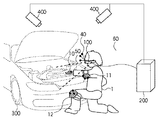
図1に示す如く、ユーザ1の人体には刺激発生部10、11、12が装着されていると共に、ユーザ1の頭部にはHMD100が装着されている。これにより、ユーザ1は、仮想物体300が存在する仮想空間を、視覚と触覚の両方で体験することができる。図1では、仮想物体300は仮想的に表現された実寸台の車を模したもので、ユーザ1は係る車のエンジンルーム内の作業についての検証を行っている。また、刺激発生部10はユーザ1の手、刺激発生部11はユーザ1のヒジ、刺激発生部12はユーザ1のヒザに、それぞれ装着されている。
As shown in FIG. 1, the
また、刺激発生部10、11、12とHMD100とには1以上のマーカ40が配されており、位置姿勢センサ400はマーカ40の位置姿勢を示す位置姿勢情報を取得する。
Further, one or
演算処理装置(情報処理装置)200には、位置姿勢センサ400が取得したマーカ40の位置姿勢情報と、HMD100から得られる現実空間の画像とが入力される。そして演算処理装置200は、後述する各種の処理を実行することで、HMD100には仮想空間画像と現実空間画像との合成画像を出力し、刺激発生部10、11、12には、それぞれの動作を制御するための動作設定情報を出力する。
The arithmetic processing device (information processing device) 200 receives the position and orientation information of the
以下では、本実施形態に係るシステムを構成する各部について詳細に説明する。 Below, each part which comprises the system which concerns on this embodiment is demonstrated in detail.
<HMD100について>
HMD100は、一般にビデオシースルー型と呼ばれるHMDであり、図2に示す如く、撮像部101と表示部102とで構成されている。
<About HMD100>
The
撮像部101は、現実空間の動画像を撮像し、撮像した各フレームの画像(現実空間画像)を、後段の演算処理装置200に対して送出する。詳しくは後述するが、係る現実空間画像には、演算処理装置200によって生成される仮想空間画像が、演算処理装置200によって合成される。そして演算処理装置200は、係る合成処理で得られる合成画像をHMD100に対して送出する。
The
表示部102は、液晶画面などにより構成されており、HMD100を頭部に装着したユーザ1の眼前に位置するようにHMD100に対して取り付けられたものである。表示部102には、演算処理装置200から送出された合成画像が表示される。もちろん、表示部102にはその他の情報を表示させるようにしても良い。
The
ここで、撮像部101の光軸と表示部102の光軸とを一致させることで、撮像部101で撮像した画像と上記合成画像との視差を無くすことができ、ユーザ1は自らの視点での仮想空間画像と現実空間画像を違和感なく見ることができる。視覚的に現実物体と仮想物体を提示する方法には公知の技術を用いれば良いため、詳細な説明は省略する。
Here, by making the optical axis of the
また、上述の通り、HMD100には、1以上のマーカ40が配されている。
Further, as described above, the
<刺激発生部10、11、12について>
上述したように、図1では、ユーザ1の手、ヒジ、ヒザにはそれぞれ刺激発生部10、11、12が装着されている。もちろん、刺激発生部の個数や装着位置についてはこれに限定するものではない。
<About the
As described above, in FIG. 1, the
本実施形態では、刺激発生部10、11、12は、グローブ形状やサポーター形状を有しており、人体に装着する為の形状を有するように構成されている。
In the present embodiment, the
図3は、刺激発生部10の概略構成を示す図である。図3に示す如く、刺激発生部10は、グローブ形状を有する本体部19と、1以上の皮膚感覚刺激部20と、で構成されている。
FIG. 3 is a diagram illustrating a schematic configuration of the
本体部19は、皮膚感覚刺激部20が発生する刺激がユーザ1の人体9(図3では手)に十分伝わるように、人体9と皮膚感覚刺激部20とを密着させる構造であることが望ましい。
The
皮膚感覚刺激部20は、例えば振動モータで構成されている。皮膚感覚刺激部20は、手のひらや手の甲等に複数配置し、仮想物体との接触部位に応じて駆動させる皮膚感覚刺激部20を選択することが好適である。
The skin
なお、ヒジ用やヒザ用のサポーター形状を有する刺激発生部11、12についても同様に、1以上の皮膚感覚刺激部20が配置されている。
Similarly, one or more skin
<皮膚感覚刺激部20について>
図3では、皮膚感覚刺激部20として、振動モータを使用した例を示した。振動モータは、モータの回転軸に取り付けられた偏心重量が回転することで振動を発生する。振動モータには、一般的にシリンダー型(円筒型)とコイン型(扁平型)があり、どちらを用いても良いが、図3ではコイン型を用いた場合の図を示している。振動モータは小型で強い刺激を発生することができるため、本実施形態のように複数の人体位置に刺激を与える場合に好適である。
<About skin
FIG. 3 shows an example in which a vibration motor is used as the skin
なお、皮膚感覚に刺激を与えるものであれば、皮膚感覚刺激部20は振動モータ以外のものであっても良い。皮膚感覚に刺激を与える方法としては、機械刺激、電気刺激、温度刺激等があり、皮膚感覚刺激部20に適用可能なデバイスは、その方法に応じて様々なものが考えられる。例えば、機械的な振動刺激を発生するボイスコイル型のデバイスを皮膚感覚刺激部20として用いても良い。また、圧電素子や高分子アクチュエータ等のアクチュエータにより人体に接触したピンを動作させて刺激を与えるデバイスを皮膚感覚刺激部20として用いても良い。また、空気圧力により皮膚表面を圧迫するデバイスを皮膚感覚刺激部20として用いても良い。また、電気刺激として、微小電極アレイを用いて刺激を与えるものなどがあり、温度刺激では、熱電素子を用いるものなどがある。
Note that the skin
このように、皮膚感覚刺激部20として用いることができるデバイスには様々なものが考えられる。以下の説明は、皮膚感覚刺激部20の動作内容(刺激強度の制御)が、演算処理装置200から設定可能なものであれば、皮膚感覚刺激部20に適用するデバイスは、如何なる方法で刺激を発生させるデバイスであっても良い。
As described above, various devices that can be used as the skin
<位置姿勢センサ400とマーカ40とについて>
上述したように、位置姿勢センサ400は、マーカ40の位置姿勢情報を取得する為のものである。従って、位置姿勢センサ400は、マーカ40を配したHMD100や刺激発生部10、11、12の位置姿勢を求めることができる。
<About the position and
As described above, the position and
位置姿勢センサ400とマーカ40とは光学式の位置姿勢取得システムであり、例えば、赤外線照射機能付きのカメラで構成される複数の位置姿勢センサ400と、再帰性反射材で構成される複数のマーカ40である。マーカ40は異なる3次元位置に配置することでID付けが行われる。なお、係る位置姿勢取得システムによって、各マーカ40を配した対象物(本実施形態の場合、HMD100、刺激発生部10、11、12)の位置姿勢情報を求める技術については周知のものであり、詳細な説明は省略する。
The position /
しかし、HMD100や刺激発生部10、11、12の位置姿勢情報を取得する方法はこれ以外にも考えられ、位置姿勢センサ400とマーカ40とを用いる方法に限定するものではない。
However, other methods for acquiring the position and orientation information of the
例えば、磁気センサシステムを用いてHMD100、刺激発生部10、11、12の位置姿勢情報を取得する方法がある。係る方法では、現実空間中に磁界を発生させるトランスミッタを設置し、HMD100と刺激発生部10、11、12には係る磁界中における自身の位置姿勢に応じた磁界の変化を検知するレシーバを装着する。そして係るレシーバが検知した結果を示す信号に基づいて、それぞれのレシーバのセンサ座標系における位置姿勢情報を求める。センサ座標系とは、トランスミッタの位置を原点とし、係る原点で互いに直交する3軸をそれぞれx軸、y軸、z軸とする座標系である。もちろん、係る位置姿勢情報の取得方法は、他の方式を用いるセンサシステム、例えば、超音波システムを用いても同様である。
For example, there is a method for acquiring position and orientation information of the
また、その他にも、HMD100や刺激発生部10、11、12に対してマーカを配し、係るマーカをカメラで撮像することで、それぞれの位置姿勢情報を取得する方法を用いても良い。
In addition, a method may be used in which markers are arranged on the
また、周知のモーションキャプチャ技術を用いて刺激発生部10、11、12の位置姿勢情報を取得するようにしても良い。
Further, the position and orientation information of the
また、図3に示すように、グローブ型の刺激発生部10を用いる場合には、手の位置姿勢を光学式センサで取得し、さらに指先の位置姿勢を機械式センサや光ファイバを用いた指先位置取得方法で取得する構成にしても良い。
Also, as shown in FIG. 3, when using the glove-
このように、HMD100、刺激発生部10、11、12の位置姿勢情報を取得する方法については特に限定するものではない。
Thus, the method for acquiring the position and orientation information of the
本実施形態では、位置姿勢センサ400が取得したHMD100の位置姿勢情報、刺激発生部10、11、12の位置姿勢情報は、演算処理装置200に対して送出される。
<演算処理装置200について>
演算処理装置200は、例えば、一般のPC(パーソナルコンピュータ)により構成されている。
In the present embodiment, the position and orientation information of the
<Regarding
The
CPU201は、RAM202やROM203に格納されているプログラムやデータを用いて演算処理装置200全体の制御を行うと共に、演算処理装置200が行うものとして後述する各処理を実行する。
The
RAM202は、データ記録部205からロードされたプログラムやデータ、位置姿勢センサ情報取得部209が位置姿勢センサ400から取得した位置姿勢情報を一時的に記憶するためのエリアを有する。更にRAM202は、画像入力部207が撮像部101から取得した現実空間画像のデータを一時的に記憶する為のエリア、CPU201が各種の処理を実行する際に用いるワークエリアを有する。即ち、RAM202は、各種のエリアを適宜提供することができる。
The
ROM203は、ブートプログラムや設定データ等を格納する。
The
操作入力部206は、操作部204を演算処理装置200に接続する為のインターフェースとして機能するものである。操作部204はキーボードやマウスなどにより構成されており、演算処理装置200の操作者が操作することで、各種の指示を操作入力部206を介してCPU201に対して入力することができる。
The
データ記録部205は、ハードディスクドライブ装置に代表される大容量情報記憶装置である。データ記録部205には、OS(オペレーティングシステム)や、演算処理装置200が行うものとして後述する各処理をCPU201に実行させるためのプログラムやデータが保存されている。
The
係るプログラムには、後述する各フローチャートに従った各処理をCPU201に実行させるためのプログラムが含まれている。また、係るデータには、仮想空間を構成する各仮想物体に係るデータや、係る仮想空間を照射する光源に係るデータなどが含まれる。また、データ記録部205には、既知の情報として説明するものや、後述する各処理を行う際に当然用いるであろうと当業者であれば容易に相当し得る情報も保存されている。
The program includes a program for causing the
データ記録部205に保存されているプログラムやデータは、CPU201による制御に従って適宜RAM202にロードされる。そしてCPU201はRAM202にロードされたプログラムやデータを用いて各処理を実行する。
Programs and data stored in the
なお、上述の説明で、RAM202に一時的に格納されるものとして説明したものは、データ記録部205に一時的に保存するようにしても良い。
Note that what has been described as being temporarily stored in the
画像入力部207、画像出力部208は、HMD100を演算処理装置200に接続する為のインターフェースとして機能する。HMD100が有する撮像部101から送出された現実空間画像のデータは、画像入力部207を介してRAM202やデータ記録部205に格納される。また、演算処理装置200が生成した合成画像は、画像出力部208を介してHMD100が有する表示部102に対して出力される。
The
位置姿勢センサ情報取得部209は、位置姿勢センサ400を演算処理装置200に接続する為のインターフェースとして機能する。位置姿勢センサ400が取得した位置姿勢情報は位置姿勢センサ情報取得部209を介して演算処理装置200内に入力され、RAM202やデータ記録部205に格納される。
The position / orientation sensor
刺激情報出力部210は、皮膚感覚刺激部20を演算処理装置200に接続する為のインターフェースとして機能する。演算処理装置200により生成された動作設定情報は、この刺激情報出力部210を介して、指定された皮膚感覚刺激部20に対して出力される。
The stimulation
画像入力部207、画像出力部208、位置姿勢センサ情報取得部209、刺激情報出力部210は、アナログビデオポート、IEEE1394等のデジタル入出力ポート、RS232C、或いはUSB等のシリアルポート、イーサネット(登録商標)等によって構成される。
The
システムバス211には、演算処理装置200を構成するものとして説明した上述の各部が接続されている。
The above-described units described as constituting the
<演算処理装置200が行う処理の概要について>
ここで、演算処理装置200が行う処理の概要について説明する。演算処理装置200は、HMD100の位置姿勢に応じた仮想空間画像を生成し、撮像部101が撮像した現実空間画像と合成して表示部102に送出する処理に加え、次のような処理を行う。
<Outline of Processing Performed by
Here, an outline of processing performed by the
即ち、刺激発生部10、11、12と仮想物体との接触の有無を検知する。そして、接触があった場合には、ユーザが注目している範囲(領域)として設定される注目範囲の中に、接触した刺激発生部が含まれているか否かを判断する。そして係る判断結果に応じて、刺激発生部10、11、12のうち接触があった刺激発生部に対する動作を制御する。
That is, the presence or absence of contact between the
図1には、注目範囲としての範囲50と、係る範囲50以外の範囲60とが示されている。ここで、範囲60を注目範囲外と呼称する。
In FIG. 1, a
ここで、注目範囲50とは、ユーザ1が視覚によって対象を知覚できる範囲及びその一部である。従って、注目範囲50は、厳密に測定された人間の視野に限るものではなく、人工的に設定されたものであっても良い。
Here, the
図1に示す如く、注目範囲50の中では、刺激発生部10を取り付けた部位(手)と仮想物体300とに仮想的な接触が発生している。一方、注目範囲外60では、刺激発生部12を取り付けた部位(ヒザ)と仮想物体300とに仮想的な接触が発生している。
As shown in FIG. 1, in the
このような場合、本実施形態では、刺激発生部10と刺激発生部12とで異なる刺激を発生させるように、これらの刺激発生部10、12を制御する。
In such a case, in the present embodiment, the
以下では、演算処理装置200が行う処理のうち、このような刺激発生部の動作制御について、より詳細に説明する。
Hereinafter, of the processes performed by the
図4は、演算処理装置200による各刺激発生部10、11、12の動作制御処理のフローチャートである。なお、図4のフローチャートに従った処理をCPU201に実行させるためのプログラムやデータは、データ記録部205に保存されている。係るプログラムやデータは、CPU201による制御に従って適宜RAM202にロードされる。そしてCPU201はこのロードされたプログラムやデータを用いて処理を実行することで、演算処理装置200は、以降説明する、図4のフローチャートに従った処理を実行することになる。
FIG. 4 is a flowchart of the operation control process of each of the
先ず、ステップS4001では、演算処理装置200の初期化処理、以降の処理で用いる様々なデータをデータ記録部205からRAM202にロードする処理を行う。係るデータには、仮想空間で用いる様々な情報(仮想空間情報)が含まれている。
First, in step S4001, an initialization process of the
次にステップS4002では、位置姿勢センサ400から送出される、HMD100の位置姿勢情報、刺激発生部10、11、12の位置姿勢情報、を、位置姿勢センサ情報取得部209を介してRAM202に取得する。
In step S4002, the position and orientation information of the
次にステップS4003では、現在のユーザ1の視点の位置姿勢情報として、ステップS4002で取得したHMD100の位置姿勢情報を設定する。更に、各刺激発生部10、11、12の位置姿勢で配置する仮想物体(以下、「部位仮想物体」と呼称する)の位置姿勢情報として、ステップS4002で取得した各刺激発生部10、11、12の位置姿勢情報を設定する。即ち、各刺激発生部10、11、12の位置姿勢で、それぞれの刺激発生部に対応する部位仮想物体を配置する。また、仮想空間中に存在するその他の仮想物体の位置姿勢が変化する場合には、その変化後の位置姿勢情報を求める。このように、仮想空間における様々な情報の更新を行う。
In step S4003, the position / orientation information of the
ここで、部位仮想物体について簡単に説明する。上述のように、刺激発生部10に対応する部位仮想物体を刺激発生部10の位置姿勢で仮想空間中に配置する。また、刺激発生部11に対応する部位仮想物体を刺激発生部11の位置姿勢で仮想空間中に配置する。また、刺激発生部12に対応する部位仮想物体を刺激発生部12の位置姿勢で仮想空間中に配置する。これにより、各刺激発生部10、11、12のそれぞれの位置姿勢が、仮想空間に対して反映されることになる。即ち、各刺激発生部10、11、12と仮想空間とのインタラクションが可能になる。
Here, the part virtual object will be briefly described. As described above, the part virtual object corresponding to the
なお、以降の説明では、部位仮想物体以外の仮想物体を、背景仮想物体と呼称する。即ち、仮想空間は背景仮想物体により構成されており、このような仮想空間中に、各刺激発生部の位置姿勢で部位仮想物体を配置するものとする。 In the following description, a virtual object other than the part virtual object is referred to as a background virtual object. That is, the virtual space is composed of background virtual objects, and the part virtual objects are arranged in such virtual spaces at the positions and orientations of the respective stimulus generators.
なお、以降の説明で、部位仮想物体、背景仮想物体に共通の説明では、これらをまとめて単に「仮想物体」と呼称する。 In the following description, in the description common to the part virtual object and the background virtual object, these are collectively referred to simply as “virtual objects”.
また、部位仮想物体がどのような仮想物体であるのかについて詳しくは後述するが、部位仮想物体は、計算上、仮想空間に配されるもので、実際に描画対象としなくても良い。 Further, although what kind of virtual object the part virtual object is will be described later in detail, the part virtual object is arranged in the virtual space in terms of calculation and does not have to be actually drawn.
ここで上述のように、図4のフローチャートに従った処理と並行して「仮想空間を構築する処理」、即ち、背景仮想物体や光源を仮想空間中に配置する処理が行われている。従ってステップS4004では、この処理で仮想空間中に配置された各背景仮想物体と、ステップS4003で配置された各部位仮想物体との干渉判定処理を行う。即ち、各背景仮想物体の何れかと各部位仮想物体の何れかとが接触しているか否かを判定する処理を行う。仮想物体同士の干渉判定処理は周知の技術である。 Here, as described above, in parallel with the processing according to the flowchart of FIG. 4, “processing for constructing a virtual space”, that is, processing for arranging a background virtual object and a light source in the virtual space is performed. Accordingly, in step S4004, interference determination processing between each background virtual object arranged in the virtual space by this process and each part virtual object arranged in step S4003 is performed. That is, a process is performed to determine whether any of the background virtual objects is in contact with any of the part virtual objects. Interference determination processing between virtual objects is a well-known technique.
次にステップS4005では、背景仮想物体と接触している部位仮想物体が、注目範囲(図1では注目範囲50に相当)内に位置しているか否かを判断する(注目判定処理)。注目範囲の求め方については後述する。また、ステップS4005における処理の詳細についても、後述する。
Next, in step S4005, it is determined whether or not the part virtual object in contact with the background virtual object is located within the attention range (corresponding to the
次にステップS4006では、背景仮想物体と接触している部位仮想物体に対応する刺激発生部の動作を制御するための動作設定情報を生成する。係る動作設定情報は、背景仮想物体と接触している部位仮想物体が、注目範囲内に位置しているか否かに応じて異なる。例えば、刺激発生部10の位置姿勢に配置した部位仮想物体と刺激発生部11の位置姿勢に配置した部位仮想物体が共に背景仮想物体に接触しているとする。しかし、前者の部位仮想物体が注目範囲内に位置しており、後者の部位仮想物体が注目範囲内に位置していない場合、刺激発生部10に対して生成する動作設定情報と、刺激発生部11に対して生成する動作設定情報とは、異なる。即ち、それぞれの動作設定情報が示す刺激の強度が異なる。
In step S4006, operation setting information for controlling the operation of the stimulus generation unit corresponding to the part virtual object in contact with the background virtual object is generated. Such operation setting information differs depending on whether or not the part virtual object that is in contact with the background virtual object is located within the range of interest. For example, it is assumed that the part virtual object arranged at the position and orientation of the
ステップS4006における処理の詳細については後述する。 Details of the processing in step S4006 will be described later.
次にステップS4007では、背景仮想物体に接触している部位仮想物体に対応する刺激発生部(実際には皮膚感覚刺激部20)に対して、この刺激発生部についてステップS4006で生成した動作設定情報を、刺激情報出力部210を介して出力する。刺激発生部は、係る動作設定情報を受信すると、係る動作設定情報が示す強度の刺激を発生すべく動作する。
Next, in step S4007, for the stimulus generation unit (actually skin sensation stimulation unit 20) corresponding to the part virtual object in contact with the background virtual object, the action setting information generated in step S4006 for this stimulus generation unit. Is output via the stimulus
次に、本処理の終了指示が操作部204から入力された、若しくは本処理の終了条件が満たされた場合には処理をステップS4008を介してステップS4009に進める。
Next, when an instruction to end the process is input from the
ステップS4009では、本処理を終了する為の終了処理を行う。 In step S4009, an end process for ending this process is performed.
一方、本処理の終了指示が操作部204から入力されてもいないし、本処理の終了条件も満たされていない場合には、処理をステップS4008を介してステップS4002に戻し、以降の処理を繰り返す。
On the other hand, if the end instruction of this process is not input from the
<ステップS4004における干渉判定処理について>
上述のステップS4004における処理、即ち、部位仮想物体と背景仮想物体との干渉判定処理についてより詳細に説明する。
<Interference Determination Processing in Step S4004>
The process in step S4004 described above, that is, the interference determination process between the part virtual object and the background virtual object will be described in more detail.
上述のように、データ記録部205には、部位仮想物体のデータ、背景仮想物体のデータが予め保存されている。ここで、各仮想物体のデータには、仮想物体の形状情報、テクスチャマップデータ等がある。形状情報には、例えば、仮想物体がポリゴンで構成されている場合、各ポリゴンの法線ベクトルデータ、ポリゴンを構成する各頂点のデータ、が含まれている。
As described above, the
部位仮想物体と背景仮想物体との干渉判定処理を行う場合、それぞれの仮想物体のデータのうち形状情報のみを用いる。しかし、仮想物体の形状が複雑である場合、形状情報のサイズは大きくなる。従って、形状が複雑な仮想物体同士の干渉判定処理を行う場合、データサイズの大きい形状情報を用いた干渉判定処理を行うことになり、処理負荷が大きくなる。従って、背景仮想物体と部位仮想物体との干渉判定処理を行う場合、背景仮想物体の形状の詳細度を落とした擬似形状仮想物体、部位仮想物体の形状の詳細度を落とした擬似形状仮想物体を生成し、擬似形状仮想物体同士で干渉判定処理を行うようにしても良い。 When performing the interference determination process between the part virtual object and the background virtual object, only the shape information is used from the data of each virtual object. However, when the shape of the virtual object is complicated, the size of the shape information increases. Therefore, when performing an interference determination process between virtual objects having complicated shapes, an interference determination process using shape information having a large data size is performed, which increases a processing load. Therefore, when performing the interference determination process between the background virtual object and the part virtual object, the pseudo-shape virtual object with a reduced detail level of the shape of the background virtual object, or a pseudo-shape virtual object with a reduced detail level of the part virtual object is used. Alternatively, the interference determination process may be performed between the pseudo-shaped virtual objects.
仮想物体の擬似形状仮想物体を生成するとは、仮想物体の形状情報から、例えば周知のポリゴンリダクション技術を用いて、よりデータ量の少ない形状情報(より低い詳細度の形状を示す形状情報)を生成することである。 Generating a virtual object pseudo-shape Virtual object is generated from shape information of a virtual object using, for example, a well-known polygon reduction technology, and shape information with a smaller amount of data (shape information indicating a shape with a lower level of detail). It is to be.
なお、このように、干渉判定処理用の形状情報を、干渉判定処理の際にリアルタイムで生成しなくても、予め作成し、データ記録部205に保存させておいても良い。
As described above, the shape information for the interference determination process may be created in advance and stored in the
なお、仮想物体同士の干渉判定処理については様々な技術があり、本実施形態では、如何なる干渉判定技術を用いても良い。また、仮想物体はポリゴン以外の要素で構築しても良く、それに応じて干渉判定処理の内容を変更しても良い。 Note that there are various technologies for the interference determination processing between virtual objects, and any interference determination technology may be used in this embodiment. The virtual object may be constructed with elements other than polygons, and the content of the interference determination process may be changed accordingly.
即ち、本実施形態では、どのような干渉判定処理を行うのかについては本筋ではなく、仮想物体同士が干渉したか否かを検知することができれば、如何なる技術を用いても良い。 That is, in this embodiment, what kind of interference determination processing is performed is not the main line, and any technique may be used as long as it can detect whether or not virtual objects interfere with each other.
<ステップS4005における判定処理について>
上述のステップS4005における処理、即ち、背景仮想物体と接触している部位仮想物体が、注目範囲(図1では注目範囲50に相当)内に位置しているか否かを判断する処理について、図5,6を用いてより詳細に説明する。
<About the determination process in step S4005>
Regarding the processing in step S4005 described above, that is, the processing for determining whether or not the part virtual object in contact with the background virtual object is located within the attention range (corresponding to the
図5は、刺激発生部10、11を装着したユーザ1の腕と、位置姿勢センサ400と、HMD100と、を含む現実空間の様子を示す図である。図6は、現実空間の状態が図5に示した状態である場合における、仮想空間の一例を示す図である。従って、HMD100を装着したユーザ1には、図5に示した現実空間と、図6に示した仮想空間とが合成された状態で提示されるのであるが、ここでは説明上、別個に示している。
FIG. 5 is a diagram illustrating a state of the real space including the arm of the
図5に示す如く、上述したように、ユーザ1の手には刺激発生部10が取り付けられており、肘には刺激発生部11が取り付けられている。刺激発生部10、11にはそれぞれ、複数のマーカ40が配されている。また、係るマーカ40は、HMD100にも配されている。そして、それぞれのマーカ40を位置姿勢センサ400が観察している。68は、HMD100の位置姿勢情報のうち姿勢成分で示される視線方向ベクトルである。係る視線方向ベクトル68は、HMD100の位置姿勢情報のうち位置情報が示す位置を始点とするベクトルである。
As shown in FIG. 5, as described above, the
一方、図6に示す如く、仮想空間には、背景仮想物体302,303が配置されている。ここで、69は、ユーザ1の視点(HMD100が図5に示した位置姿勢を有している状態で、位置姿勢センサ400がHMD100の位置姿勢として測定した位置姿勢を有する視点)を示している。
On the other hand, as shown in FIG. 6, background
311は、刺激発生部10の位置姿勢で配された部位仮想物体、312は、刺激発生部11の位置姿勢で配された部位仮想物体を示す。なお、図6では、それぞれの部位仮想物体311、312は、対応する刺激発生部10、11の形状を模した仮想物体であるが、係る形状は特に限定するものではない。しかし、部位仮想物体は、対応する刺激発生部の形状を模した仮想物体、若しくは対応する刺激発生部を装着する人体の部位の形状を模した仮想物体であることが好ましい。これは、刺激発生部やそれを装着する人体の部位の実際の形状と背景仮想物体との干渉判定処理を実現することで、よりリアリティのある干渉判定処理を行う為である。
55は、視点69の位置姿勢情報や画角情報等の視点情報に基づいて計算されるビューボリュームである。係るビューボリューム55としては、例えば、一般に仮想空間画像を描画する際に設定されるビューボリューム(仮想空間を見るための仮想的な視野に相当するビューボリューム)がある。この場合、ビューボリューム55は、HMD100の表示部102に描画される仮想空間の範囲を示す。図6では、ビューボリューム55は、HMD100の水平画角と垂直画角、視線方向ベクトル68に垂直な2つの面から構成されている。係る2つの面とは、視点69に近い面(前方クリッピング面)と視点69から遠い面(後方クリッピング面)である。なお、ビューボリューム55は、視点に関する情報が変化すればその度に再計算されるもので、その形状やサイズについては適宜決定すれば良い。また、ビューボリューム55を生成するために必要な情報(視点69の位置姿勢情報以外)については、予めデータ記録部205に記録しておく。ここでは、ビューボリューム55を注目範囲として用いる。
ここで、図6では、部位仮想物体311と背景仮想物体302とが接触しており、部位仮想物体312と背景仮想物体303とが接触している。そして更に図6では、部位仮想物体311はビューボリューム55の内部に位置しており、部位仮想物体312はビューボリューム55の外部に位置している。
Here, in FIG. 6, the part
ここで、背景仮想物体と接触している部位仮想物体のうち、注目範囲に含まれている部位仮想物体に対応する刺激発生部に対しては、ユーザ1は注意を払っていると推定することができる。逆に、注目範囲に含まれていない部位仮想物体に対応する刺激発生部に対しては、ユーザ1は注意を払っていないと推定することができる。
Here, it is assumed that the
本実施形態では、注目範囲として求めたビューボリュームと、背景仮想物体と接触している部位仮想物体と、の位置関係に応じて、それぞれの部位仮想物体についてビューボリューム55に対する内外判定処理を行う。
In the present embodiment, the inside / outside determination processing for the
図6の場合、背景仮想物体302と接触している部位仮想物体311はビューボリューム55の内部に位置しているので、ユーザ1は、刺激発生部10を装着した部位については注意を払っていると推定する。一方、背景仮想物体303と接触している部位仮想物体312はビューボリューム55の外部に位置しているので、ユーザ1は、刺激発生部11を装着した部位については注意は払っていないと推定する。
In the case of FIG. 6, the part
そしてこの場合、刺激発生部10と刺激発生部11とには、それぞれ異なる強度の刺激を発生させるべく、刺激発生部10、刺激発生部11のそれぞれに対する動作設定情報を生成することになる。
In this case, the
図7は、ステップS4005における処理の詳細を示すフローチャートである。 FIG. 7 is a flowchart showing details of the processing in step S4005.
なお、ステップS4005では、全ての部位仮想物体を処理対象とするのではなく、ステップS4004における干渉判定処理で背景仮想物体と接触したと判断された部位仮想物体が処理対象となる。 In step S4005, not all part virtual objects are processed, but a part virtual object determined to have contacted the background virtual object in the interference determination process in step S4004 is processed.
ステップS7001では、背景仮想物体と接触したと判断された部位仮想物体のそれぞれの位置情報が示す位置が、視点情報に基づいて設定されるビューボリューム(注目範囲)の内部であるのか外部であるのかを判断する。 In step S7001, whether the position indicated by the position information of each part virtual object determined to be in contact with the background virtual object is inside or outside the view volume (attention range) set based on the viewpoint information. Judging.
係る判断処理の結果、ビューボリュームの内部に位置する部位仮想物体についてはステップS7002において、係る部位仮想物体に固有の識別情報(例えばID)をRAM202に記録する。一方、ビューボリュームの外部に位置する部位仮想物体についてはステップS7003において、係る部位仮想物体に固有の識別情報(例えばID)をRAM202に記録する。
As a result of the determination process, for the part virtual object located inside the view volume, identification information (for example, ID) unique to the part virtual object is recorded in the
なお、以上の説明では、仮想空間の表示用のビューボリュームを注目範囲として用いたが、四角錐や所定の形状の空間をHMD100の視線方向に設定したものを注目範囲としてもよい。例えば、図8では、ビューボリューム55よりも狭い空間を注目範囲(注目判定空間)56として設定している。これは、表示領域の周辺部も注目している可能性が低いとして、注目判定空間56を見えている範囲(ビューボリューム55)よりも狭く設定している。この注目判定空間56の内部に、背景仮想物体と接触している部位仮想物体が存在している場合、注目していると判定する。図8は、注目範囲の他の設定方法について説明する図である。
In the above description, the view volume for displaying the virtual space is used as the attention range, but a square pyramid or a space having a predetermined shape may be set in the viewing direction of the
また、図8では、ビューボリューム55の後方クリッピング面に相当する面も、視点69の位置方向にずらして、比較的狭い注目判定空間56を設定している。本実施形態のように、人体に直接装着する形態の刺激発生部では、表示に使われるビューボリュームほど遠方の仮想物体に触れることはあり得ないため、接触に関する注目範囲に特化した空間としてカスタマイズされている。
Further, in FIG. 8, the surface corresponding to the rear clipping surface of the
注目範囲のカスタマイズについては、人間の視覚特性やタスク(検証作業)内容などを考慮して決定すると良い。例えば、人間の視野は、垂直方向に上側60度、下側75度程度であると言われていることから、表示装置がそれ以上の画角を有する場合にも、上側60度、下側75度程度の範囲を注目範囲として設定する。またさらに、人間の視野内には、分解能の高い中心視野があり、視覚で確認しながら作業を行う(注目して物体に触れる)場合には、中心視野で物体を観察していると考えられる。従って、中心視野付近に注目範囲を設定するようにしても良い。また、タスクによって注目している範囲が狭い、広いという違いがあると考えられる。そこで、操作対象や検証内容などによって、所定の注目範囲を予め決定するようにしても良い。また、予め眼球運動の計測などによりタスク作業中の注目範囲を推定しておき、その結果から注目範囲を設定するようにしても良い。 The attention range customization may be determined in consideration of human visual characteristics and task (verification work) contents. For example, since the human visual field is said to be about 60 degrees on the upper side and about 75 degrees on the lower side in the vertical direction, even when the display device has a larger angle of view, the upper side is 60 degrees and the lower side 75 A range of about degrees is set as the attention range. Furthermore, there is a high-resolution central visual field in the human visual field, and when working while visually confirming (touching an object with attention), it is considered that the object is observed in the central visual field. . Therefore, the attention range may be set near the central visual field. Moreover, it is thought that there is a difference that the range of attention is narrow and wide depending on the task. Therefore, a predetermined range of interest may be determined in advance according to the operation target, verification contents, and the like. Alternatively, the attention range during task work may be estimated in advance by measuring eye movements, and the attention range may be set based on the result.
即ち、注目範囲の設定については様々な方法があり、適宜決定すればよい。しかし何れにせよ、視点の位置姿勢が変われば、それに応じて注目範囲は設定し直すことになる。 That is, there are various methods for setting the attention range, and it may be determined as appropriate. In any case, however, if the position and orientation of the viewpoint changes, the range of interest is reset accordingly.
<ステップS4006における動作設定情報の生成処理について>
上述のステップS4006における処理、即ち、背景仮想物体と接触している部位仮想物体に対応する刺激発生部の動作を制御するための動作設定情報を生成する処理についてより詳細に説明する。
<Regarding Generation Processing of Operation Setting Information in Step S4006>
The process in step S4006 described above, that is, the process of generating action setting information for controlling the action of the stimulus generator corresponding to the part virtual object that is in contact with the background virtual object will be described in more detail.
図9は、ステップS4006における処理の詳細を示すフローチャートである。 FIG. 9 is a flowchart showing details of the processing in step S4006.
上記ステップS7002においてRAM202に記録した識別情報については、ステップS9002で処理対象となる。一方、上記ステップS7003においてRAM202に記録した識別情報については、ステップS9003で処理対象となる。
The identification information recorded in the
ステップS9002では、ステップS7002でRAM202に記録した識別情報に対応する部位仮想物体を特定する。そして、特定した部位仮想物体に対応する刺激発生部に対して設定すべき動作設定情報(注目範囲内用の動作設定情報)を生成(設定)する。
In step S9002, a part virtual object corresponding to the identification information recorded in the
一方、ステップS9003では、ステップS7003でRAM202に記録した識別情報に対応する部位仮想物体を特定する。そして、特定した部位仮想物体に対応する刺激発生部に対して設定すべき動作設定情報(注目範囲外用の動作設定情報)を生成(設定)する。
On the other hand, in step S9003, a part virtual object corresponding to the identification information recorded in the
図6の場合、刺激発生部10に対しては注目範囲内用の動作設定情報を設定し、刺激発生部11に対しては注目範囲外用の動作設定情報を設定する。
In the case of FIG. 6, operation setting information for the attention range is set for the
なお、どの刺激発生部にどの部位仮想物体が関連付けられているのか(どの刺激発生部の位置姿勢にどの部位仮想物体が配されているのか)を示す対応関係情報は予めデータ記録部205に記録しておく。これにより、部位仮想物体に対応する刺激発生部を特定することができる。
Correspondence information indicating which part virtual object is associated with which stimulus generation part (which part virtual object is arranged at which position and orientation of which stimulus generation part) is recorded in the
そして上記ステップS4007では、上記ステップS7002でRAM202に記録した識別情報に対応する部位仮想物体が関連付けられている刺激発生部には、ステップS9002で設定した動作設定情報を、刺激情報出力部210を介して出力する。
In step S4007, the motion setting information set in step S9002 is sent to the stimulus generation unit associated with the part virtual object corresponding to the identification information recorded in the
また、上記ステップS4007では、上記ステップS7003でRAM202に記録した識別情報に対応する部位仮想物体が関連付けられている刺激発生部には、ステップS9003で設定した動作設定情報を、刺激情報出力部210を介して出力する。
In step S4007, the motion information set in step S9003 is sent to the stimulus
本実施形態において、刺激制御の好適な例としては、注目範囲内での接触で発生させる刺激に比べて、注目範囲外での接触で発生させる刺激を強く設定することである。即ち、背景仮想物体と接触している部位仮想物体が注目範囲の中に含まれている場合には、この部位仮想物体に対応する刺激発生部に第1の強度の刺激を発生させるための動作設定情報を設定する。また、背景仮想物体と接触している部位仮想物体が注目範囲の中に含まれていない場合には、この部位仮想物体に対応する刺激発生部に第2の強度の刺激を発生させるための動作設定情報を設定する。なお、第1の強度は、第2の強度よりも弱い。 In the present embodiment, a preferable example of stimulus control is to set the stimulus generated by the contact outside the attention range to be stronger than the stimulation generated by the contact within the attention range. That is, when a part virtual object that is in contact with the background virtual object is included in the attention range, an operation for generating a first intensity stimulus in the stimulus generation unit corresponding to the part virtual object Set configuration information. In addition, when a part virtual object in contact with the background virtual object is not included in the attention range, an operation for generating a stimulus having the second intensity in the stimulus generation unit corresponding to the part virtual object Set configuration information. The first intensity is weaker than the second intensity.
皮膚感覚刺激部20に振動モータを用いて、PWM制御により動作させる場合には、予め異なる振動強度を出力する2つのデューティー比を設定しておく。そして、背景仮想物体と接触している部位仮想物体が注目範囲の中に含まれている場合には、この部位仮想物体に対応する刺激発生部に対して、低いデューティー比を動作設定情報として設定する。また、背景仮想物体と接触している部位仮想物体が注目範囲の中に含まれていない場合には、この部位仮想物体に対応する刺激発生部に対して、高いデューティー比を動作設定情報として設定する。
When using a vibration motor for the skin
このようにして設定した動作設定情報を刺激発生部へと出力すると、背景仮想物体と接触している部位仮想物体が注目範囲の中に含まれている場合には、この部位仮想物体に対応する刺激発生部では比較的弱い刺激が発生する。一方で、背景仮想物体と接触している部位仮想物体が注目範囲の中に含まれていない場合には、この部位仮想物体に対応する刺激発生部では比較的強い刺激が発生する。ユーザは、背景仮想物体に触れたことを振動刺激の触感として認識することができ、特に注目範囲外での接触では強い刺激を受けることから、注意を払っていない接触でも明確に刺激を認識することができるようになる。 When the operation setting information set in this way is output to the stimulus generation unit, if a part virtual object in contact with the background virtual object is included in the attention range, the part virtual object corresponds to the part virtual object. A relatively weak stimulus is generated in the stimulus generator. On the other hand, when a part virtual object in contact with the background virtual object is not included in the attention range, a relatively strong stimulus is generated in the stimulus generation unit corresponding to the part virtual object. The user can recognize the touch of the background virtual object as a tactile sensation of the vibration stimulus, and receives a strong stimulus especially when the contact is outside the attention range, so the stimulus is clearly recognized even when the contact is not paid attention. Will be able to.
また、設定する動作設定情報は、デューティー比に限ることはない。例えば、振動モータの制御を入力電圧のアナログ値で制御する場合には、低電圧と高電圧の値を動作設定情報として設定することで、刺激発生部により強い刺激と弱い刺激を出力することができる。また、皮膚感覚刺激部20に使用するデバイスによっては、デバイスの駆動周波数や振幅を変化させることで、刺激の強弱を表現しても良い。一般に、機械的な皮膚刺激を与えた場合には、200Hz付近の刺激が最も感度が高いと言われている。そこで、注目範囲外の領域で与える強い刺激を200Hz付近に設定し、注目範囲内で表現する刺激を100Hz以下の刺激にすることにより、周波数変更により刺激の強弱を表現することができるようになる。この場合、動作設定情報は、各周波数値となる。
Further, the operation setting information to be set is not limited to the duty ratio. For example, when controlling the vibration motor with an analog value of the input voltage, by setting the low voltage and high voltage values as operation setting information, the stimulus generator can output strong and weak stimuli. it can. Moreover, depending on the device used for the skin
また、異なる刺激として、異なるパターンの刺激で表現しても良い。 Further, different stimuli may be expressed as different stimuli.
図10は、それぞれ異なる刺激に対応する波形のグラフを示す図である。 FIG. 10 is a graph showing waveforms corresponding to different stimuli.
図10(a)には、連続的な刺激出力のグラフが示されており、図10(b)には、刺激が矩形波となる出力のグラフが示されている。そして、それぞれの刺激のパターンを、注目範囲内の刺激、注目範囲外の刺激として割り当てても良い。特に、図10(a)に示したパターンを注目範囲内用の刺激、図10(b)に示したパターンを注目範囲外用の刺激に割り当てることが望ましい。これは、図10(a)に示したパターンにより注目範囲内での継続的な接触表現を行い、人間にとって認識しやすい刺激である図10(b)に示したパターンにより注意喚起としての刺激を表現することができるためである。 FIG. 10A shows a continuous stimulus output graph, and FIG. 10B shows an output graph in which the stimulus is a rectangular wave. Then, each stimulus pattern may be assigned as a stimulus within the attention range and a stimulus outside the attention range. In particular, it is desirable to assign the pattern shown in FIG. 10A to the stimulus within the attention range, and assign the pattern shown in FIG. 10B to the stimulus outside the attention range. This is a continuous contact expression within the attention range by the pattern shown in FIG. 10 (a), and the stimulus shown in FIG. This is because it can be expressed.
即ち、注目範囲の中に刺激発生部が含まれている場合には、この刺激発生部に第1の刺激を発生させる為の動作設定情報を生成し、注目範囲の中に刺激発生部が含まれていない場合には、この刺激発生部に第2の刺激を発生させる為の動作設定情報を生成する。なお、第1の刺激と第2の刺激とは異なる刺激である。 That is, when a stimulus generation unit is included in the attention range, operation setting information for generating the first stimulus is generated in the stimulus generation unit, and the stimulus generation unit is included in the attention range. If not, operation setting information for generating a second stimulus in the stimulus generator is generated. Note that the first stimulus and the second stimulus are different stimuli.
また、注目範囲内での接触、または注目範囲外での接触のいずれかでのみ刺激を出力し、もう一方では刺激出力を行わない制御を行ってもよい。 Alternatively, a control may be performed in which a stimulus is output only by a contact within the attention range or a contact outside the attention range, and the stimulation output is not performed on the other side.
以上の説明により、本実施形態によれば、注目範囲の内外で異なる刺激を発生させることができるようになり、注目範囲外で注意を払っていない人体の部位に対して、接触情報を十分に伝えることができるようになる。 As described above, according to the present embodiment, different stimuli can be generated inside and outside the attention range, and contact information is sufficiently provided to a part of the human body not paying attention outside the attention range. You will be able to communicate.
なお、以上説明した構成によれば、ユーザが注目範囲外の接触により強い刺激を受け、刺激部位に目を向けることに伴って仮想空間中の視点の位置姿勢も変更すると、一転して接触部位は注目範囲内となるので、刺激量が注目範囲内のものに変更される。 Note that, according to the configuration described above, when the user receives a strong stimulus due to contact outside the range of interest, and changes the position and orientation of the viewpoint in the virtual space as he looks at the stimulus site, the contact site is turned over. Is within the attention range, the amount of stimulation is changed to that within the attention range.
HMD100のトラッキングの情報に基づいた動的な注目範囲変更により、注意喚起のための接触状態刺激と意識的な接触を表現する刺激を自然に切り替えることができるようになる。HMD100のトラッキングは、人体頭部の位置姿勢または表示装置の位置姿勢情報を取得することを意味する。
By dynamically changing the attention range based on the tracking information of the
[第2の実施形態]
部位仮想物体が注目範囲内に位置しているか否かを判定するための方法には様々なものがある。本実施形態では、撮像部101により撮像された現実空間画像を画像処理することで、部位仮想物体が注目範囲内に位置しているか否かを判定する。
[Second Embodiment]
There are various methods for determining whether or not the part virtual object is located within the attention range. In the present embodiment, it is determined whether or not the region virtual object is located within the attention range by performing image processing on the real space image captured by the
なお、本実施形態に係るシステムは、第1の実施形態と同じであるものとし、以下説明する点が、第1の実施形態と異なる。 The system according to this embodiment is the same as that of the first embodiment, and the points described below are different from those of the first embodiment.
図11は、撮像部101により撮像された現実空間画像の一例を示す図である。410は、現実空間画像であり、図11に示す如く、現実空間画像410内には、背景仮想物体305、ユーザ1の腕1199、刺激発生部10が映っている。更に、刺激発生部10には、2次元バーコード45、マーカ40が配されており、これらも現実空間画像410内に映っている。図11では、刺激発生部10に対応する部位仮想物体は、背景仮想物体305に接触しているものとする。
FIG. 11 is a diagram illustrating an example of a real space image captured by the
2次元バーコード45は、刺激発生部10に固有の識別情報(例えばID)を示すものである。従って、刺激発生部10に固有の識別情報を示すことができるものであれば、2次元バーコード45以外のものを用いても良い。
The two-
本実施形態では、現実空間画像410内(画像中)に刺激発生部が映っている場合には、注目範囲内にこの刺激発生部が位置しているものと判断する。より具体的には、現実空間画像410内で2次元バーコード45を検知し、その2次元バーコード45の認識が成功すれば、係る認識で特定される「2次元バーコード45が示す刺激発生部」が注目範囲内に位置していると判断する。
In this embodiment, when the stimulus generation part is reflected in the real space image 410 (in the image), it is determined that the stimulus generation part is located within the attention range. More specifically, if the two-
図11では、2次元バーコード45を検出し、認識すると、「現実空間画像410内に刺激発生部10を示す2次元バーコード45が存在する」と判断することができるので、刺激発生部10に対して、注目範囲内用の動作設定情報を設定する。
In FIG. 11, if the two-
2次元バーコード45を検知するために行う、現実空間画像410に対する画像処理の範囲は、現実空間画像410の全域を行っても良いし、予め画像処理を行わない部分をマスクし、所定の範囲のみを画像処理対象とするようにしても良い。所定の範囲は、表示部102の表示範囲に対応させて選択しても良いし、中心視野範囲を考慮し、画像周辺部の画素をマスクする設定にしても良い。
The range of image processing performed on the
なお、図11では、現実空間画像410外での刺激発生部10の位置姿勢を取得するため、マーカ40を刺激発生部10に配している。これは、現実空間画像410外(注目範囲外)での刺激発生部10の位置姿勢を取得し、対応する部位仮想物体と背景仮想物体との接触判定を行うためである。
In FIG. 11, the
本実施形態では、実際にユーザが観察している画像を用いて、注目範囲に対する部位仮想物体の内外判定を行うので、その判定結果が、現実の状況に即したものになる。例えば、図11で、刺激発生部10と撮像部101との間に他の現実物体が存在する場合には、刺激発生部10が現実物体に隠れて撮影される。この場合には、2次元バーコード45は認識されず、「2次元バーコード45が示す刺激発生部10」が注目範囲内には位置していない判断する。
In the present embodiment, the inside / outside determination of the part virtual object with respect to the attention range is performed using the image actually observed by the user, and the determination result is in accordance with the actual situation. For example, in FIG. 11, when another real object exists between the
ユーザは物体に隠れた刺激発生部の位置姿勢を十分に確認することができない状況にあるため、この状況を注目範囲外と判定することにより、現実の状況に即した判定を行うことができる。 Since the user is in a situation where the position and orientation of the stimulus generation unit hidden behind the object cannot be sufficiently confirmed, it is possible to make a judgment according to the actual situation by judging this situation as outside the attention range.
[第3の実施形態]
刺激発生部が注目範囲と注目範囲外の境界にわたって存在する場合、上記ステップS4005で行う注目判定処理として予め定めた処理方法を用いることが望ましい。
[Third Embodiment]
When the stimulus generation unit exists over the boundary between the attention range and the attention range, it is desirable to use a predetermined processing method as the attention determination process performed in step S4005.
一つ目の方法としては、刺激発生部が少しでも注目範囲に存在する場合には、注目(背景仮想物体と接触している部位仮想物体が注目範囲内に位置している)と判定する方法である。 As a first method, when the stimulus generation unit is present in the attention range even a little, it is determined that attention is given (the part virtual object that is in contact with the background virtual object is located in the attention range). It is.
二つ目の方法は、対象となる刺激発生部が完全に注目範囲に入っている場合のみを、注目と判定する方法である。この場合は、刺激発生部が境界に存在する場合は、注目範囲外として扱われる。 The second method is a method of determining that attention is paid only when the target stimulus generation unit is completely within the attention range. In this case, when the stimulus generator is present at the boundary, it is treated as outside the attention range.
さらに、境界に存在する場合を特別な場合として、特別な判定を与えても良い。第1の実施形態のように、注目範囲を仮想空間中に設定して注目判定処理を行う場合には、仮想空間中で部位仮想物体が注目範囲と注目範囲外の境界にまたがって存在する場合を境界に存在するとする。一方、第2の実施形態のように画像処理により注目判定処理を行う場合には、画像の周辺部においてマーカの一部のみが確認された場合を境界に存在すると判定する。 Furthermore, a special determination may be given with the case where it exists at the boundary as a special case. When the attention range is set in the virtual space and the attention determination process is performed as in the first embodiment, the part virtual object exists across the boundary between the attention range and the attention range in the virtual space. Is at the boundary. On the other hand, when the attention determination process is performed by image processing as in the second embodiment, it is determined that the case where only a part of the marker is confirmed in the peripheral portion of the image exists at the boundary.
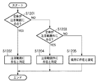
図12は、注目範囲の内外、境界、の何れに、背景仮想物体と接触している部位仮想物体が位置しているのかを判断する為の処理のフローチャートである。なお、図12のフローチャートに従った処理は、上記ステップS4005で行うものである。以下の説明では、ビューボリュームなどを用いて仮想空間中に注目範囲を設定した場合に、背景仮想物体と接触している部位仮想物体が注目範囲の内外、境界、の何れに位置しているのかを判断するものとする。 FIG. 12 is a flowchart of a process for determining whether the part virtual object in contact with the background virtual object is located in the inside or outside of the attention range or the boundary. Note that the processing according to the flowchart of FIG. 12 is performed in step S4005. In the following description, when a range of interest is set in the virtual space using a view volume or the like, whether the part virtual object in contact with the background virtual object is located inside or outside the range of interest or the boundary Shall be judged.
なお、ステップS4005では、全ての部位仮想物体を処理対象とするのではなく、ステップS4004における干渉判定処理で背景仮想物体と接触したと判断された部位仮想物体が処理対象となる。 In step S4005, not all part virtual objects are processed, but a part virtual object determined to have contacted the background virtual object in the interference determination process in step S4004 is processed.
ステップS1201では、背景仮想物体と接触したと判断されたそれぞれの部位仮想物体について、部位仮想物体の全体が注目範囲内に収まっているか否かを判断する。 In step S1201, for each part virtual object determined to have contacted the background virtual object, it is determined whether or not the whole part virtual object is within the attention range.
収まっていると判断された部位仮想物体については、ステップS1202における処理対象となる。一方、収まっていないと判断された部位仮想物体については、ステップS1203における処理対象となる。 The part virtual object determined to be within the range is a processing target in step S1202. On the other hand, the part virtual object that is determined not to fit is the processing target in step S1203.
ステップS1202では、全体が注目範囲内に収まっている部位仮想物体に固有の識別情報(例えばID)をRAM202に記録する。
In step S <b> 1202, identification information (for example, ID) unique to the part virtual object that is entirely within the attention range is recorded in the
ステップS1203では、ステップS1201で収まっていないと判断された部位仮想物体について、部位仮想物体の全体が注目範囲外に収まっているか否かを判断する。 In step S1203, it is determined whether or not the whole part virtual object is out of the attention range for the part virtual object determined not to be contained in step S1201.
収まっていると判断された部位仮想物体については、ステップS1204における処理対象となる。一方、収まっていないと判断された部位仮想物体については、ステップS1205における処理対象となる。 The part virtual object determined to be within the range is a processing target in step S1204. On the other hand, the part virtual object that is determined not to be contained is the processing target in step S1205.
ステップS1204では、全体が注目範囲外に収まっている部位仮想物体に固有の識別情報(例えばID)をRAM202に記録する。
In step S <b> 1204, identification information (for example, ID) unique to the part virtual object that is entirely outside the attention range is recorded in the
ステップS1205では、注目範囲と注目範囲外の境界に位置している部位仮想物体(ステップS1201,S1203の何れの判断でも該当しない仮想物体)に固有の識別情報(例えばID)をRAM202に記録する。
In step S1205, identification information (for example, ID) unique to the part virtual object (virtual object that does not correspond to any judgment in steps S1201 and S1203) located at the boundary between the attention range and the attention range is recorded in the
そして、その後、ステップS4006では、上記3通りのぞれぞれについて動作設定情報を設定する。例えば、全体が注目範囲内に収まっている部位仮想物体、全体が注目範囲外に収まっている部位仮想物体が存在する場合には、第1の実施形態と同様に動作設定情報を設定する。 Thereafter, in step S4006, operation setting information is set for each of the above three types. For example, when there is a part virtual object that is entirely within the attention range and a part virtual object that is entirely outside the attention range, the operation setting information is set as in the first embodiment.
また、注目範囲と注目範囲外の境界に位置する部位仮想物体に対応する刺激発生部については、例えば、次のような動作設定情報を設定する。即ち、全体が注目範囲外に収まっている部位仮想物体に対応する刺激発生部に発生させる刺激強度と、全体が注目範囲内に収まっている部位仮想物体に対応する刺激発生部に発生させる刺激強度と、の中間強度を示す動作設定情報を設定する。 In addition, for example, the following operation setting information is set for the stimulus generation unit corresponding to the part virtual object located at the boundary between the attention range and the attention range. That is, the stimulus intensity generated in the stimulus generator corresponding to the part virtual object that is entirely within the attention range, and the stimulus intensity generated in the stimulus generator corresponding to the part virtual object that is entirely within the attention range And operation setting information indicating the intermediate intensity between the two.
以上の説明により、本実施形態によれば、注目範囲周辺の接触でも、注目範囲に比べて強い刺激を設定することにより、注目の度合いに応じた刺激をユーザに与えることができる。 As described above, according to the present embodiment, a stimulus according to the degree of attention can be given to the user by setting a stronger stimulus than the range of interest even in contact around the range of interest.
[第4の実施形態]
以上の実施形態では、刺激発生部に皮膚感覚刺激部を取り付け、皮膚感覚刺激を人体に与えていた。しかし、例えば、音を発生する音源部を刺激発生部に取り付けることで、音刺激を人体に与えるようにしても良い。ここで、音源部は例えば小型のスピーカである。ユーザに接触を知らせる目的から、皮膚感覚刺激を用いることは好適であるが、皮膚感覚刺激を与える装置は皮膚(人体)との密着性が要求される場合が多く、刺激発生部の着脱が煩雑になる場合が多い。一方、音による接触通知は手軽に使用できるという観点から優れている。皮膚感覚刺激部の代わりに音源部を使用する場合にも、注目範囲の内外で発生音量や音の内容などを変化させることで、注目範囲外での接触に気づきやすくなる。
[Fourth Embodiment]
In the above embodiment, the skin sensory stimulation part is attached to the stimulus generating part, and skin sensory stimulation is given to the human body. However, for example, sound stimulation may be applied to the human body by attaching a sound source unit that generates sound to the stimulus generation unit. Here, the sound source unit is, for example, a small speaker. Although it is preferable to use skin sensory stimulation for the purpose of notifying the user of contact, devices that provide skin sensory stimulation often require close contact with the skin (human body), and the attachment and detachment of the stimulus generator is complicated. In many cases. On the other hand, contact notification by sound is excellent from the viewpoint that it can be used easily. Even when the sound source unit is used instead of the skin sensation stimulating unit, it is easy to notice contact outside the attention range by changing the generated sound volume or the content of the sound inside or outside the attention range.
音により接触情報を表現する場合、外部スピーカを使用することも可能であるが、接触位置に近い場所に小型のスピーカを配置し、接触位置が音で判断できるようにすることが望ましい。更に、上記実施形態で示した振動と、音と、を併用すると、リアル感が増すため望ましい。 When the contact information is expressed by sound, an external speaker can be used, but it is desirable to arrange a small speaker near the contact position so that the contact position can be determined by sound. Furthermore, it is desirable to use the vibration and sound shown in the above embodiment in combination because the real feeling increases.
尚、ユーザの作業中に別の音が発生している場合や、複数の作業者で同時に作業を行う場合、複数の音が発生して分かりにくくなる。その場合には、皮膚感覚刺激を優先して使用すると良い。このように作業の状態に応じて使用する刺激発生部を適時変更しても良い。 In addition, when another sound is generated during the user's work, or when the work is performed simultaneously by a plurality of workers, a plurality of sounds are generated and are difficult to understand. In that case, it is better to prioritize skin sensory stimulation. As described above, the stimulus generation unit to be used may be changed in a timely manner according to the work state.
[第5の実施形態]
以上の実施形態では、ステップS4005における処理では、全ての部位仮想物体を処理対象とするのではなく、ステップS4004における干渉判定処理で背景仮想物体と接触したと判断された部位仮想物体を処理対象としていた。
[Fifth Embodiment]
In the above embodiment, in the process in step S4005, not all part virtual objects are processed, but a part virtual object determined to have contacted the background virtual object in the interference determination process in step S4004 is processed. It was.
本実施形態では、先に、部位仮想物体が注目範囲内に位置しているか否かを判断し、その後で、部位仮想物体と背景仮想物体との干渉判定処理を行う。 In the present embodiment, it is first determined whether or not the part virtual object is located within the range of interest, and thereafter, interference determination processing between the part virtual object and the background virtual object is performed.
図13は、演算処理装置200による各刺激発生部10、11、12の動作制御処理のフローチャートである。なお、図13において、図4と同じステップには同じステップ番号を付けており、その説明は省略する。
FIG. 13 is a flowchart of the operation control process of each
ステップS1304では、全ての部位仮想物体について、注目範囲内に位置しているか否かを判断する。注目範囲に対する部位仮想物体の内外判定処理については、上述の通りである。 In step S1304, it is determined whether all the part virtual objects are located within the attention range. The inside / outside determination process of the part virtual object with respect to the attention range is as described above.
そして、ステップS1305では、全ての部位仮想物体について、背景仮想物体との干渉判定処理を行う。 In step S1305, an interference determination process with the background virtual object is performed for all the part virtual objects.
注目範囲に対する部位仮想物体の内外判定処理を、部位仮想物体と背景仮想物体との干渉判定処理に先立って行うことにより、先の処理の結果を後段の処理で用いることができる。 By performing the internal / external determination process of the part virtual object with respect to the attention range prior to the interference determination process between the part virtual object and the background virtual object, the result of the previous process can be used in the subsequent process.
例えば、注目範囲内に位置していると判断された部位仮想物体については、より詳細な形状の形状情報を用いて背景仮想物体との干渉判定処理を行う。一方、注目範囲外に位置している判断された部位仮想物体については、より簡易な形状情報を用いて背景仮想物体との干渉判定処理を行う。 For example, for the part virtual object determined to be located within the attention range, the interference determination process with the background virtual object is performed using shape information of a more detailed shape. On the other hand, for the determined part virtual object located outside the attention range, an interference determination process with the background virtual object is performed using simpler shape information.
具体的には、図6に示した仮想空間の場合、部位仮想物体311についてはより手に近い形状で背景仮想物体との干渉判定処理を行い、部位仮想物体312については単純な形状(例えば円柱等の形状)で背景仮想物体との干渉判定処理を行う。
Specifically, in the case of the virtual space shown in FIG. 6, the part
このように、接触判定の処理を制御することにより、注目範囲外での接触判定による計算コストを削減することができる。 In this way, by controlling the contact determination process, it is possible to reduce the calculation cost due to the contact determination outside the attention range.
そして、背景仮想物体と接触している部位仮想物体のうち、注目範囲内に位置している部位仮想物体、注目範囲外に位置している部位仮想物体のそれぞれについては、上記実施形態と同様の処理を行う。 Of the part virtual objects in contact with the background virtual object, the part virtual object located within the attention range and the part virtual object located outside the attention range are the same as those in the above embodiment. Process.
[第6の実施形態]
第1の実施形態で説明したように、注目範囲内で部位仮想物体と背景仮想物体とが接触した場合に発生させる刺激に比べて、注目範囲外で部位仮想物体と背景仮想物体とが接触した場合に発生させる刺激を強く設定することが好ましい。即ち、背景仮想物体と接触している部位仮想物体が注目範囲の中に含まれている場合には、この部位仮想物体に対応する刺激発生部に第1の強度の刺激を発生させるための動作設定情報を設定する。また、背景仮想物体と接触している部位仮想物体が注目範囲の中に含まれていない場合には、この部位仮想物体に対応する刺激発生部に第2の強度の刺激を発生させるための動作設定情報を設定する。なお、第1の強度は、第2の強度よりも弱い。
[Sixth Embodiment]
As described in the first embodiment, the part virtual object and the background virtual object are in contact with each other outside the attention range as compared with the stimulus generated when the part virtual object and the background virtual object are in contact with each other within the attention range. It is preferable to set a strong stimulus to be generated. That is, when a part virtual object that is in contact with the background virtual object is included in the attention range, an operation for generating a first intensity stimulus in the stimulus generation unit corresponding to the part virtual object Set configuration information. In addition, when a part virtual object in contact with the background virtual object is not included in the attention range, an operation for generating a stimulus having the second intensity in the stimulus generation unit corresponding to the part virtual object Set configuration information. The first intensity is weaker than the second intensity.
しかし、注目範囲外での接触について継続的に強い刺激を発生させた場合には、ユーザが接触を認識した上でもさらに強い刺激が継続することになる。例えば、図1でユーザ1がヒザの部分の接触を理解した上で作業検証を行う場合に、継続的に強い刺激をヒザ部分に受けていると、刺激提示を煩わしく感じる可能性がある。そこで、本実施形態では、注目範囲外で部位仮想物体と背景仮想物体とが接触した場合に発生させる刺激は、接触開始時から所定時間(予め定められた時間)の間のみ発生させる、とする。
However, when a strong stimulus is continuously generated for a contact outside the attention range, the stronger stimulus continues even after the user recognizes the contact. For example, in FIG. 1, when the
図14は、部位仮想物体と背景仮想物体との接触が注目範囲外で継続した場合に発生させる刺激の強度を、時系列に示したグラフを示す図である。図14では、部位仮想物体と背景仮想物体との接触が0秒のタイミングで発生したとする。本実施形態では、図14に示すように、接触開始時から予め定められた時間だけ経過した後(図14では1.5秒後)に、刺激強度を第一段階から第二段階に低下させる。 FIG. 14 is a graph showing, in time series, the intensity of the stimulus generated when the contact between the part virtual object and the background virtual object continues outside the attention range. In FIG. 14, it is assumed that the contact between the part virtual object and the background virtual object occurs at the timing of 0 seconds. In this embodiment, as shown in FIG. 14, after a predetermined time has elapsed from the start of contact (1.5 seconds in FIG. 14), the stimulation intensity is reduced from the first stage to the second stage. .
係る制御により、注目範囲外での接触を気づきやすくさせる効果と、強い刺激が続くことの煩わしさの解消を両立することができる。少なくとも第一段階の刺激強度は、注目範囲内における刺激強度よりも高くすることが好適である。 By such control, it is possible to achieve both the effect of easily recognizing the contact outside the attention range and the elimination of the troublesomeness of continuing strong stimulation. It is preferable that at least the stimulus intensity at the first stage is higher than the stimulus intensity within the range of interest.
即ち、本実施形態では、第2の強度の刺激を発生させるために刺激発生部に設定させる動作設定情報は、予め定められた時間内のみ第2の刺激を刺激発生部に発生させるための動作設定情報である。 That is, in the present embodiment, the operation setting information to be set in the stimulus generation unit in order to generate the second intensity stimulus is an operation for causing the stimulus generation unit to generate the second stimulus only within a predetermined time. Setting information.
[第7の実施形態]
上記実施形態では、刺激発生部と背景仮想物体との干渉判定処理を行うために、刺激発生部の位置姿勢に部位仮想物体を配置し、係る部位仮想物体と背景仮想物体との干渉判定処理を行った。また上記実施形態では、刺激発生部が注目範囲の内側に位置しているのか外側に位置しているのかを判断するためにも、部位仮想物体を用いた。
[Seventh Embodiment]
In the above embodiment, in order to perform the interference determination process between the stimulus generation unit and the background virtual object, the part virtual object is arranged at the position and orientation of the stimulus generation unit, and the interference determination process between the part virtual object and the background virtual object is performed. went. Moreover, in the said embodiment, also in order to judge whether the irritation | stimulation generation | occurrence | production part is located inside the attention range, or outside, the site | part virtual object was used.
このように、部位仮想物体を用いることで、現実世界の形状を仮想空間に反映することが可能となり、詳細な上記各判定を行うことができる。しかし、計算コストの面では、不利になる側面がある。そこで、本実施形態では、各皮膚感覚刺激部の位置を取得し、仮想空間に反映させる。 As described above, by using the part virtual object, the shape of the real world can be reflected in the virtual space, and the detailed determinations described above can be performed. However, there is a disadvantage in terms of calculation cost. Therefore, in the present embodiment, the position of each skin sensation stimulation unit is acquired and reflected in the virtual space.
例えば、グローブ型の刺激発生部の各指先に皮膚感覚刺激部が配されている場合、それぞれの皮膚感覚刺激部の位置を仮想空間中にポイントとして反映させる。そして、そのポイントを部位仮想物体として用いる。 For example, when a skin sensation stimulation unit is arranged at each fingertip of the glove-type stimulation generation unit, the position of each skin sensation stimulation unit is reflected as a point in the virtual space. Then, the point is used as a part virtual object.
このように、本実施形態によれば、ボリュームのある部位仮想物体を用いないので、計算コストとしては上記実施形態よりも有利となる。一方、多くの皮膚感覚刺激部が用いられる場合には、それぞれの皮膚感覚刺激部の現実空間中での位置を取得することは困難となるので、各実施形態で説明した何れの構成を採用するのかは使用用途ごとに考慮すればよい。 As described above, according to the present embodiment, since a part virtual object having a volume is not used, the calculation cost is more advantageous than the above embodiment. On the other hand, when many skin sensation stimulating units are used, it is difficult to acquire the position of each skin sensation stimulating unit in the real space, so any configuration described in each embodiment is adopted. Whether or not it should be considered for each application.
なお、本実施形態では、仮想空間に反映させる現実空間の情報が、体積を持たないポイントであるため、皮膚感覚刺激部の位置情報のみを取得すれば良い。すなわち、姿勢情報が必要なくなるため、皮膚感覚刺激部については、位置姿勢センサではなく、3自由度のセンサを使用することができる。 In the present embodiment, since the information of the real space reflected in the virtual space is a point having no volume, it is only necessary to acquire the position information of the skin sensory stimulation unit. That is, since posture information is not necessary, a sensor with three degrees of freedom can be used for the skin sensation stimulating unit instead of the position and posture sensor.
[第8の実施形態]
上記実施形態では、部位仮想物体は現実空間中での刺激発生部の形状を模したものであるとした。しかし、係る形状は上述の通り、特に限定するものではない。例えば、グローブ型の刺激発生部を使用する場合であっても、係る刺激発生部の位置姿勢に配置する部位仮想物体の形状は円柱形状としても良い。
[Eighth Embodiment]
In the above-described embodiment, the region virtual object is assumed to imitate the shape of the stimulus generator in the real space. However, the shape is not particularly limited as described above. For example, even when a glove-type stimulus generator is used, the shape of the part virtual object arranged at the position and orientation of the stimulus generator may be a cylindrical shape.
また例えば、グローブ型の刺激発生部の位置姿勢で配置する部位仮想物体として、手に工具を把持した形状の仮想物体を用いても良い。もちろん、係る仮想物体は、背景仮想物体との干渉判定処理、注目範囲に対する内外判定処理のみに用いるだけでなく、実際に表示しても良い。これにより、仮想的な工具を使用して作業検証を行うことができるようになる。 Further, for example, a virtual object having a shape in which a tool is held by a hand may be used as a part virtual object arranged at the position and orientation of the glove-type stimulus generator. Of course, such a virtual object is not only used for the interference determination process with the background virtual object and the inside / outside determination process for the attention range, but may be actually displayed. This makes it possible to perform work verification using a virtual tool.
また、上記実施形態では、刺激発生部は、人体に装着する為の形状を有するように構成されているものとしたが、これに限定するものではない。例えば、棒状の刺激発生部に複数の皮膚感覚刺激部を設置する構成としても良い。この場合、部位仮想物体の形状をドライバやスパナなどの工具形状として、実際の刺激発生部の形状と異なるものに設定し、表示する。これにより、ユーザは工具を使用した作業を仮想的に体験することができるようになる。把持型の刺激発生部は、人体による直感的な操作感が失われる可能性があるものの、装着の煩雑さを改善することができる。また、現実の作業のシミュレーションを仮想空間で効果的に行うことができるようになる。 Moreover, in the said embodiment, although the irritation | stimulation generation | occurrence | production part shall be comprised so that it may have a shape for mounting | wearing a human body, it is not limited to this. For example, it is good also as a structure which installs a some skin sensory stimulation part in a rod-shaped irritation | stimulation generation | occurrence | production part. In this case, the shape of the part virtual object is set as a tool shape such as a driver or a spanner to be different from the actual shape of the stimulus generation unit and displayed. As a result, the user can virtually experience the work using the tool. Although the grip-type stimulus generator may lose the intuitive operational feeling of the human body, it can improve the complexity of wearing. In addition, real work simulation can be effectively performed in the virtual space.
[第9の実施形態]
上記実施形態では、頭部装着型表示装置の一例としてHMD100を用いた。しかし、頭部装着型表示装置としてHMD100以外のものを用いてもよいし、頭部装着型表示装置以外の表示装置を用いても良い。例えば、ヘッドトラッキングにより視線方向を特定できる形態や、表示装置自体のトラッキングにより仮想的な視線方向がトラッキングできる形態であれば良く、如何なる表示装置を用いても良い。
[Ninth Embodiment]
In the above embodiment, the
ヘッドトラッキングを実現する環境としては、例えば、大型のディスプレイと偏光眼鏡により立体視を行うシステムがある。この場合、偏光眼鏡の位置姿勢から、注目範囲を設定することができる。 As an environment for realizing head tracking, for example, there is a system that performs stereoscopic viewing with a large display and polarized glasses. In this case, the attention range can be set from the position and orientation of the polarized glasses.
[第10の実施形態]
上記実施形態では、注目範囲内で部位仮想物体と背景仮想物体とが接触した場合に発生させる刺激に比べて、注目範囲外で部位仮想物体と背景仮想物体とが接触した場合に発生させる刺激を強く設定する例などを説明した。但し、振動モータなどの皮膚感覚刺激部を用いる場合、同じ刺激強度でも人体の取り付け場所によって感じる強度が異なる場合がある。
[Tenth embodiment]
In the above embodiment, compared to the stimulus generated when the part virtual object and the background virtual object are in contact with each other within the attention range, the stimulus generated when the part virtual object and the background virtual object are in contact with outside the attention range. The example of setting strongly was explained. However, when using a skin sensation stimulating unit such as a vibration motor, the strength to be felt may differ depending on the attachment location of the human body even with the same stimulation strength.
例えば、人の指先は刺激に対して敏感に反応するが、ヒザやヒジはあまり敏感に反応しない。このため、人体の異なる部位に皮膚感覚刺激部を装着する場合は、事前に各部位を仮想物体と接触させ、同じ刺激強度と感じる値をあらかじめ各部位の基準強度として設定しておくと望ましい。そして、この基準強度を元にして、各部位の刺激強度を、注目範囲内か、注目範囲外かで異なる値とすれば、全身の各部位でも、仮想物体との接触を注目範囲内外でより明瞭に提示させることができる。 For example, human fingertips respond sensitively to stimuli, but knees and elbows do not respond very sensitively. For this reason, when attaching a skin sensation stimulating unit to different parts of the human body, it is desirable that each part is brought into contact with a virtual object in advance, and a value that feels the same stimulation intensity is set in advance as a reference intensity of each part. Based on this reference intensity, if the stimulation intensity of each part is set to a different value depending on whether it is within the attention range or outside the attention range, the contact with the virtual object is more or less within the attention range within each part of the whole body. It can be presented clearly.
なお、本実施形態は、刺激発生強度を例として説明したが、提示パターンや周波数など他の制御方法でも同様である。 In addition, although this embodiment demonstrated the irritation | stimulation intensity | strength as an example, it is the same also with other control methods, such as a presentation pattern and a frequency.
また、以上で説明した各実施形態は適宜組み合わせて用いても良い。 Further, the embodiments described above may be used in appropriate combination.
[その他の実施形態]
また、本発明の目的は、以下のようにすることによって達成されることはいうまでもない。即ち、前述した実施形態の機能を実現するソフトウェアのプログラムコードを記録した記録媒体(または記憶媒体)を、システムあるいは装置に供給する。係る記憶媒体は言うまでもなく、コンピュータ読み取り可能な記憶媒体である。そして、そのシステムあるいは装置のコンピュータ(またはCPUやMPU)が記録媒体に格納されたプログラムコードを読み出し実行する。この場合、記録媒体から読み出されたプログラムコード自体が前述した実施形態の機能を実現することになり、そのプログラムコードを記録した記録媒体は本発明を構成することになる。
[Other Embodiments]
Needless to say, the object of the present invention can be achieved as follows. That is, a recording medium (or storage medium) that records a program code of software that implements the functions of the above-described embodiments is supplied to a system or apparatus. Needless to say, such a storage medium is a computer-readable storage medium. Then, the computer (or CPU or MPU) of the system or apparatus reads and executes the program code stored in the recording medium. In this case, the program code itself read from the recording medium realizes the functions of the above-described embodiment, and the recording medium on which the program code is recorded constitutes the present invention.
また、コンピュータが読み出したプログラムコードを実行することにより、そのプログラムコードの指示に基づき、コンピュータ上で稼働しているオペレーティングシステム(OS)などが実際の処理の一部または全部を行う。その処理によって前述した実施形態の機能が実現される場合も含まれることは言うまでもない。 Further, by executing the program code read by the computer, an operating system (OS) or the like running on the computer performs part or all of the actual processing based on the instruction of the program code. Needless to say, the process includes the case where the functions of the above-described embodiments are realized.
さらに、記録媒体から読み出されたプログラムコードが、コンピュータに挿入された機能拡張カードやコンピュータに接続された機能拡張ユニットに備わるメモリに書込まれたとする。その後、そのプログラムコードの指示に基づき、その機能拡張カードや機能拡張ユニットに備わるCPUなどが実際の処理の一部または全部を行い、その処理によって前述した実施形態の機能が実現される場合も含まれることは言うまでもない。 Furthermore, it is assumed that the program code read from the recording medium is written in a memory provided in a function expansion card inserted into the computer or a function expansion unit connected to the computer. After that, based on the instruction of the program code, the CPU included in the function expansion card or function expansion unit performs part or all of the actual processing, and the function of the above-described embodiment is realized by the processing. Needless to say.
本発明を上記記録媒体に適用する場合、その記録媒体には、先に説明したフローチャートに対応するプログラムコードが格納されることになる。 When the present invention is applied to the recording medium, program code corresponding to the flowchart described above is stored in the recording medium.
Claims (9)
前記ユーザの人体に取り付けた、刺激を発生する刺激発生部の位置情報を取得する手段と、
前記仮想物体の位置姿勢情報と、前記刺激発生部の位置情報と、を用いて、前記仮想物体と前記刺激発生部とが接触しているか否かを判断する接触判断手段と、
前記仮想物体と前記刺激発生部とが接触していると判断された場合には、前記視点の位置に応じて生成される注目範囲の中に前記刺激発生部が含まれているか否かを判断する判断手段と、
前記注目範囲の中に前記刺激発生部が含まれていると前記判断手段が判断した場合には、前記刺激発生部に第1の刺激を発生させるための動作設定情報を生成し、前記注目範囲の中に前記刺激発生部が含まれていないと前記判断手段が判断した場合には、前記刺激発生部に前記第1の刺激とは異なる第2の刺激を発生させるための動作設定情報を生成し、該生成した動作設定情報を前記刺激発生部に対して出力する出力手段と
を備えることを特徴とする情報処理装置。 An information processing apparatus that generates an image of a virtual space in which a virtual object is arranged based on position and orientation information of a user's viewpoint,
Means for acquiring position information of a stimulus generator that generates a stimulus attached to the human body of the user;
Contact determining means for determining whether or not the virtual object and the stimulus generator are in contact with each other using the position and orientation information of the virtual object and the position information of the stimulus generator;
When it is determined that the virtual object is in contact with the stimulus generation unit, it is determined whether the stimulus generation unit is included in the attention range generated according to the position of the viewpoint. A judgment means to
When the determination unit determines that the stimulus generation unit is included in the attention range, operation setting information for generating a first stimulus in the stimulus generation unit is generated, and the attention range is generated. If the determination means determines that the stimulus generator is not included in the stimulus generation unit, operation setting information is generated for causing the stimulus generator to generate a second stimulus different from the first stimulus. And an output means for outputting the generated operation setting information to the stimulus generator.
前記視点からの現実空間の画像を取得する手段と、
前記現実空間の画像と、前記仮想空間の画像とを合成した合成画像を、表示装置に対して出力する手段と
を備えることを特徴とする請求項1に記載の情報処理装置。 Furthermore,
Means for acquiring an image of a real space from the viewpoint;
The information processing apparatus according to claim 1, further comprising: a unit that outputs a composite image obtained by combining the image of the real space and the image of the virtual space to a display device.
前記現実空間の画像中に前記刺激発生部が含まれているか否かを判断することで、前記注目範囲の中に前記刺激発生部が含まれているか否かを判断することを特徴とする請求項2に記載の情報処理装置。 The determination means includes
The determination as to whether or not the stimulus generator is included in the range of interest by determining whether or not the stimulus generator is included in the image of the real space. Item 3. The information processing device according to Item 2.
前記情報処理装置が有する取得手段が、前記ユーザの人体に取り付けた、刺激を発生する刺激発生部の位置情報を取得する工程と、
前記情報処理装置が有する接触判断手段が、前記仮想物体の位置姿勢情報と、前記刺激発生部の位置情報と、を用いて、前記仮想物体と前記刺激発生部とが接触しているか否かを判断する接触判断工程と、
前記情報処理装置が有する判断手段が、前記仮想物体と前記刺激発生部とが接触していると判断された場合には、前記視点の位置に応じて生成される注目範囲の中に前記刺激発生部が含まれているか否かを判断する判断工程と、
前記情報処理装置が有する出力手段が、前記注目範囲の中に前記刺激発生部が含まれていると前記判断工程で判断した場合には、前記刺激発生部に第1の刺激を発生させるための動作設定情報を生成し、前記注目範囲の中に前記刺激発生部が含まれていないと前記判断工程で判断した場合には、前記刺激発生部に前記第1の刺激とは異なる第2の刺激を発生させるための動作設定情報を生成し、該生成した動作設定情報を前記刺激発生部に対して出力する出力工程と
を備えることを特徴とする情報処理方法。 An information processing method performed by an information processing apparatus that generates an image of a virtual space in which a virtual object is arranged based on position and orientation information of a user's viewpoint,
An acquisition unit included in the information processing apparatus acquires position information of a stimulus generation unit that generates a stimulus attached to the human body of the user;
Whether the virtual object and the stimulus generator are in contact with each other is determined by the contact determination means of the information processing apparatus using the position and orientation information of the virtual object and the position information of the stimulus generator. A contact determination process for determining;
When the determination unit included in the information processing apparatus determines that the virtual object is in contact with the stimulus generation unit, the stimulus is generated within the attention range generated according to the position of the viewpoint. A determination step of determining whether or not a part is included;
When the output unit of the information processing apparatus determines in the determination step that the stimulus generation unit is included in the attention range, the output unit is configured to generate the first stimulus in the stimulus generation unit. If the determination step determines that the stimulus generation unit is not included in the attention range by generating operation setting information, a second stimulus different from the first stimulus is generated in the stimulus generation unit. An information processing method comprising: generating operation setting information for generating the output, and outputting the generated operation setting information to the stimulus generation unit.
Priority Applications (4)
| Application Number | Priority Date | Filing Date | Title |
|---|---|---|---|
| JP2007234713A JP4989383B2 (en) | 2007-09-10 | 2007-09-10 | Information processing apparatus and information processing method |
| US12/207,322 US8553049B2 (en) | 2007-09-10 | 2008-09-09 | Information-processing apparatus and information-processing method |
| CN2008102123462A CN101387908B (en) | 2007-09-10 | 2008-09-10 | Information-processing apparatus and information-processing method |
| EP08164081A EP2034390A3 (en) | 2007-09-10 | 2008-09-10 | Information-processing apparatus and information-processing method |
Applications Claiming Priority (1)
| Application Number | Priority Date | Filing Date | Title |
|---|---|---|---|
| JP2007234713A JP4989383B2 (en) | 2007-09-10 | 2007-09-10 | Information processing apparatus and information processing method |
Publications (3)
| Publication Number | Publication Date |
|---|---|
| JP2009069918A JP2009069918A (en) | 2009-04-02 |
| JP2009069918A5 JP2009069918A5 (en) | 2010-11-04 |
| JP4989383B2 true JP4989383B2 (en) | 2012-08-01 |
Family
ID=40090038
Family Applications (1)
| Application Number | Title | Priority Date | Filing Date |
|---|---|---|---|
| JP2007234713A Expired - Fee Related JP4989383B2 (en) | 2007-09-10 | 2007-09-10 | Information processing apparatus and information processing method |
Country Status (4)
| Country | Link |
|---|---|
| US (1) | US8553049B2 (en) |
| EP (1) | EP2034390A3 (en) |
| JP (1) | JP4989383B2 (en) |
| CN (1) | CN101387908B (en) |
Cited By (1)
| Publication number | Priority date | Publication date | Assignee | Title |
|---|---|---|---|---|
| US11954324B2 (en) | 2020-07-22 | 2024-04-09 | Samsung Electronics Co., Ltd. | Method for performing virtual user interaction, and device therefor |
Families Citing this family (59)
| Publication number | Priority date | Publication date | Assignee | Title |
|---|---|---|---|---|
| JP4876141B2 (en) * | 2009-05-21 | 2012-02-15 | 関東自動車工業株式会社 | Work guide system, work guide method, and recording medium recording the work guide method |
| JP5062774B2 (en) * | 2009-05-21 | 2012-10-31 | トヨタ自動車東日本株式会社 | Work training system, work training method, and recording medium recording the work training method |
| KR20100138700A (en) * | 2009-06-25 | 2010-12-31 | 삼성전자주식회사 | Method and apparatus for processing virtual world |
| JP5342354B2 (en) * | 2009-07-17 | 2013-11-13 | 日本放送協会 | Haptic presentation device and haptic presentation program |
| KR101651568B1 (en) * | 2009-10-27 | 2016-09-06 | 삼성전자주식회사 | Apparatus and method for three-dimensional space interface |
| JP5920862B2 (en) * | 2011-03-08 | 2016-05-18 | 株式会社ソニー・インタラクティブエンタテインメント | Information processing apparatus, information processing method, computer program, and information processing system |
| EP3654147A1 (en) * | 2011-03-29 | 2020-05-20 | QUALCOMM Incorporated | System for the rendering of shared digital interfaces relative to each user's point of view |
| US20130022950A1 (en) * | 2011-07-22 | 2013-01-24 | Muniz Simas Fernando Moreira | Method and system for generating behavioral studies of an individual |
| JP5844880B2 (en) * | 2012-03-01 | 2016-01-20 | パイオニア株式会社 | Head mounted display, calibration method and calibration program, and recording medium |
| US9741145B2 (en) * | 2012-06-29 | 2017-08-22 | Disney Enterprises, Inc. | Augmented reality simulation continuum |
| DE102012017700A1 (en) * | 2012-09-07 | 2014-03-13 | Sata Gmbh & Co. Kg | System and method for simulating operation of a non-medical tool |
| US20140198130A1 (en) * | 2013-01-15 | 2014-07-17 | Immersion Corporation | Augmented reality user interface with haptic feedback |
| JP6143469B2 (en) * | 2013-01-17 | 2017-06-07 | キヤノン株式会社 | Information processing apparatus, information processing method, and program |
| US20140253540A1 (en) * | 2013-03-07 | 2014-09-11 | Yoav DORI | Method and system of incorporating real world objects into a virtual environment |
| US9833697B2 (en) * | 2013-03-11 | 2017-12-05 | Immersion Corporation | Haptic sensations as a function of eye gaze |
| US9333649B1 (en) * | 2013-03-15 | 2016-05-10 | Industrial Perception, Inc. | Object pickup strategies for a robotic device |
| WO2014147946A1 (en) * | 2013-03-21 | 2014-09-25 | ソニー株式会社 | Acceleration sensation presentation device, acceleration sensation presentation method, and acceleration sensation presentation system |
| JP2014191718A (en) | 2013-03-28 | 2014-10-06 | Sony Corp | Display control device, display control method, and recording medium |
| US9367136B2 (en) * | 2013-04-12 | 2016-06-14 | Microsoft Technology Licensing, Llc | Holographic object feedback |
| WO2014171200A1 (en) * | 2013-04-16 | 2014-10-23 | ソニー株式会社 | Information processing device and information processing method, display device and display method, and information processing system |
| JP6138566B2 (en) * | 2013-04-24 | 2017-05-31 | 川崎重工業株式会社 | Component mounting work support system and component mounting method |
| KR101367412B1 (en) * | 2013-06-18 | 2014-02-24 | 우석 계 | Apparatus for controlling physical effects in cyber space and method therefor |
| JP5888372B2 (en) * | 2013-08-29 | 2016-03-22 | キヤノンマーケティングジャパン株式会社 | Information processing system, processing method thereof, and program |
| JP6344029B2 (en) * | 2014-04-16 | 2018-06-20 | 富士通株式会社 | Display method, display program, and display device |
| US9690370B2 (en) | 2014-05-05 | 2017-06-27 | Immersion Corporation | Systems and methods for viewport-based augmented reality haptic effects |
| US10379614B2 (en) * | 2014-05-19 | 2019-08-13 | Immersion Corporation | Non-collocated haptic cues in immersive environments |
| CN203941499U (en) * | 2014-05-30 | 2014-11-12 | 贺杰 | A kind of action collection and feedback system based on stereoscopic vision |
| US9911232B2 (en) | 2015-02-27 | 2018-03-06 | Microsoft Technology Licensing, Llc | Molding and anchoring physically constrained virtual environments to real-world environments |
| US10684485B2 (en) | 2015-03-06 | 2020-06-16 | Sony Interactive Entertainment Inc. | Tracking system for head mounted display |
| US10296086B2 (en) | 2015-03-20 | 2019-05-21 | Sony Interactive Entertainment Inc. | Dynamic gloves to convey sense of touch and movement for virtual objects in HMD rendered environments |
| US10156908B2 (en) * | 2015-04-15 | 2018-12-18 | Sony Interactive Entertainment Inc. | Pinch and hold gesture navigation on a head-mounted display |
| US9898864B2 (en) | 2015-05-28 | 2018-02-20 | Microsoft Technology Licensing, Llc | Shared tactile interaction and user safety in shared space multi-person immersive virtual reality |
| US9836117B2 (en) | 2015-05-28 | 2017-12-05 | Microsoft Technology Licensing, Llc | Autonomous drones for tactile feedback in immersive virtual reality |
| JP2017010387A (en) * | 2015-06-24 | 2017-01-12 | キヤノン株式会社 | System, mixed-reality display device, information processing method, and program |
| JP6725827B2 (en) * | 2015-07-31 | 2020-07-22 | キヤノンマーケティングジャパン株式会社 | Information processing apparatus, information processing system, control method thereof, and program |
| EP3179336A1 (en) * | 2015-12-07 | 2017-06-14 | Thomson Licensing | Method and device for rendering haptic effects in an immersive content |
| DE102016001369B4 (en) * | 2016-02-06 | 2018-03-29 | Audi Ag | Method for automatic user adaptation of the stimulus characteristic of an active control element of a vehicle |
| JP6736944B2 (en) * | 2016-03-29 | 2020-08-05 | ソニー株式会社 | Information processing device, information processing method, and program |
| US10198855B2 (en) | 2016-07-20 | 2019-02-05 | Colopl, Inc. | Method of providing virtual space, method of providing virtual experience, system and medium for implementing the methods |
| JP6189495B1 (en) * | 2016-07-20 | 2017-08-30 | 株式会社コロプラ | Method for providing virtual space, method for providing virtual experience, program, and recording medium |
| CN106249890A (en) * | 2016-07-28 | 2016-12-21 | 深圳市金立通信设备有限公司 | The control method of a kind of virtual reality device and virtual reality device |
| US20190369713A1 (en) * | 2016-10-19 | 2019-12-05 | Sony Corporation | Display control apparatus, display control method, and program |
| CN106390447B (en) * | 2016-11-22 | 2018-01-12 | 深圳市超级人生科技有限公司 | Proprioceptive simulation equipment with passive stimulatory function |
| US10427039B2 (en) * | 2016-12-08 | 2019-10-01 | Immersion Corporation | Haptic surround functionality |
| US20190287285A1 (en) * | 2016-12-12 | 2019-09-19 | Sony Corporation | Information processing device, information processing method, and program |
| US10139934B2 (en) * | 2016-12-22 | 2018-11-27 | Microsoft Technology Licensing, Llc | Magnetic tracker dual mode |
| CN110366746B (en) * | 2017-02-24 | 2022-08-16 | 维拉达公司 | Virtual reality-based image diagnosis exercise device and method |
| JP6469752B2 (en) * | 2017-04-24 | 2019-02-13 | 株式会社コロプラ | INFORMATION PROCESSING METHOD, INFORMATION PROCESSING PROGRAM, INFORMATION PROCESSING SYSTEM, AND INFORMATION PROCESSING APPARATUS |
| JP6867883B2 (en) * | 2017-06-01 | 2021-05-12 | 株式会社日立ドキュメントソリューションズ | Spatial display device and spatial display method |
| JP2019008623A (en) * | 2017-06-27 | 2019-01-17 | キヤノン株式会社 | Information processing apparatus, information processing apparatus control method, computer program, and storage medium |
| US10628982B2 (en) * | 2018-05-14 | 2020-04-21 | Vulcan Inc. | Augmented reality techniques |
| JP2019219492A (en) * | 2018-06-19 | 2019-12-26 | ニチアス株式会社 | Fastening experiencing system |
| CN112313603B (en) | 2018-06-28 | 2024-05-17 | 索尼公司 | Encoding device, encoding method, decoding device, decoding method, and program |
| WO2020008716A1 (en) * | 2018-07-03 | 2020-01-09 | ソニー株式会社 | Encoding device, encoding method, decoding device, decoding method, transmission system, receiving device, and program |
| US10678342B2 (en) * | 2018-10-21 | 2020-06-09 | XRSpace CO., LTD. | Method of virtual user interface interaction based on gesture recognition and related device |
| CN110989838B (en) * | 2019-11-29 | 2022-09-02 | 维沃移动通信有限公司 | Wearable device, control method thereof, and computer-readable storage medium |
| WO2022065120A1 (en) * | 2020-09-28 | 2022-03-31 | ソニーグループ株式会社 | Information processing device, information processing method, and program |
| US11462016B2 (en) * | 2020-10-14 | 2022-10-04 | Meta Platforms Technologies, Llc | Optimal assistance for object-rearrangement tasks in augmented reality |
| CN114049871A (en) * | 2022-01-13 | 2022-02-15 | 腾讯科技(深圳)有限公司 | Audio processing method and device based on virtual space and computer equipment |
Family Cites Families (19)
| Publication number | Priority date | Publication date | Assignee | Title |
|---|---|---|---|---|
| US5999185A (en) * | 1992-03-30 | 1999-12-07 | Kabushiki Kaisha Toshiba | Virtual reality control using image, model and control data to manipulate interactions |
| JPH0869449A (en) * | 1994-08-26 | 1996-03-12 | Matsushita Electric Works Ltd | Simulation device for bodily feeling three-dimensional body |
| JPH09120464A (en) * | 1995-08-21 | 1997-05-06 | Matsushita Electric Ind Co Ltd | Rehabilitation support device |
| JP2000501033A (en) | 1995-11-30 | 2000-02-02 | ヴァーチャル テクノロジーズ インコーポレイテッド | Human / machine interface with tactile feedback |
| JP2000350865A (en) * | 1999-06-11 | 2000-12-19 | Mr System Kenkyusho:Kk | Game device for composite real space, image processing method therefor and program storage medium |
| US6409599B1 (en) * | 1999-07-19 | 2002-06-25 | Ham On Rye Technologies, Inc. | Interactive virtual reality performance theater entertainment system |
| JP2001229408A (en) * | 2000-02-18 | 2001-08-24 | Hitachi Zosen Corp | Stereoscopic virtual image bodily sensation system |
| JP2003316493A (en) * | 2002-04-19 | 2003-11-07 | Seiko Epson Corp | Tactile sense presentation device |
| US20040095311A1 (en) * | 2002-11-19 | 2004-05-20 | Motorola, Inc. | Body-centric virtual interactive apparatus and method |
| JP4063131B2 (en) * | 2003-04-15 | 2008-03-19 | セイコーエプソン株式会社 | Image processing apparatus and tactile / force-sensing method |
| JP4401728B2 (en) * | 2003-09-30 | 2010-01-20 | キヤノン株式会社 | Mixed reality space image generation method and mixed reality system |
| SE0401582L (en) * | 2004-06-18 | 2005-05-10 | Totalfoersvarets Forskningsins | Interactive procedure for presenting information in an image |
| WO2006006686A1 (en) * | 2004-07-15 | 2006-01-19 | Nippon Telegraph And Telephone Corporation | Inner force sense presentation device, inner force sense presentation method, and inner force sense presentation program |
| WO2007064456A2 (en) * | 2005-11-28 | 2007-06-07 | The George Washington University | Virtual reality simulator harness systems |
| KR100812624B1 (en) | 2006-03-02 | 2008-03-13 | 강원대학교산학협력단 | Stereovision-Based Virtual Reality Device |
| JP4921113B2 (en) * | 2006-10-25 | 2012-04-25 | キヤノン株式会社 | Contact presentation apparatus and method |
| US8985774B2 (en) * | 2007-03-30 | 2015-03-24 | National Institute Of Information And Communication Technology | Floating image interaction device and its program |
| US8717360B2 (en) * | 2010-01-29 | 2014-05-06 | Zspace, Inc. | Presenting a view within a three dimensional scene |
| US8854298B2 (en) * | 2010-10-12 | 2014-10-07 | Sony Computer Entertainment Inc. | System for enabling a handheld device to capture video of an interactive application |
-
2007
- 2007-09-10 JP JP2007234713A patent/JP4989383B2/en not_active Expired - Fee Related
-
2008
- 2008-09-09 US US12/207,322 patent/US8553049B2/en active Active
- 2008-09-10 EP EP08164081A patent/EP2034390A3/en not_active Withdrawn
- 2008-09-10 CN CN2008102123462A patent/CN101387908B/en not_active Expired - Fee Related
Cited By (1)
| Publication number | Priority date | Publication date | Assignee | Title |
|---|---|---|---|---|
| US11954324B2 (en) | 2020-07-22 | 2024-04-09 | Samsung Electronics Co., Ltd. | Method for performing virtual user interaction, and device therefor |
Also Published As
| Publication number | Publication date |
|---|---|
| CN101387908A (en) | 2009-03-18 |
| EP2034390A2 (en) | 2009-03-11 |
| JP2009069918A (en) | 2009-04-02 |
| EP2034390A3 (en) | 2011-11-02 |
| US8553049B2 (en) | 2013-10-08 |
| CN101387908B (en) | 2010-10-06 |
| US20090066725A1 (en) | 2009-03-12 |
Similar Documents
| Publication | Publication Date | Title |
|---|---|---|
| JP4989383B2 (en) | Information processing apparatus and information processing method | |
| JP4926799B2 (en) | Information processing apparatus and information processing method | |
| JP4921113B2 (en) | Contact presentation apparatus and method | |
| US10248210B2 (en) | Systems and methods for haptically-enabled conformed and multifaceted displays | |
| CN108334190B (en) | Haptic feedback using field of view | |
| US10220317B2 (en) | Haptic sensations as a function of eye gaze | |
| JP2009276996A (en) | Information processing apparatus, and information processing method | |
| US10317997B2 (en) | Selection of optimally positioned sensors in a glove interface object | |
| CN105094311B (en) | Systems and methods for viewport-based augmented reality haptic effects | |
| KR100812624B1 (en) | Stereovision-Based Virtual Reality Device | |
| CA2675999C (en) | System and method for the interactive display of data in a motion capture environment | |
| JP2018136938A (en) | Automatic localized haptics generation system | |
| US11467668B2 (en) | System and method for representing virtual object information with haptic stimulation | |
| EP3489804A1 (en) | Haptic accessory apparatus | |
| US20180011538A1 (en) | Multimodal haptic effects | |
| CN108604130A (en) | Information processing equipment, information processing method and non-transitory computer-readable medium | |
| CN107479687A (en) | For waiting for an opportunity the touch feedback of display | |
| JP2015153387A (en) | Virtual reality experiencing device, virtual reality experiencing method, and program | |
| Yong et al. | Stereo‐Vision‐Based Human‐Computer Interaction with Tactile Stimulation | |
| KR20220140498A (en) | human interface system | |
| Ikei et al. | Haptic texture presentation in a three-dimensional space |
Legal Events
| Date | Code | Title | Description |
|---|---|---|---|
| A521 | Request for written amendment filed |
Free format text: JAPANESE INTERMEDIATE CODE: A523 Effective date: 20100910 |
|
| A621 | Written request for application examination |
Free format text: JAPANESE INTERMEDIATE CODE: A621 Effective date: 20100910 |
|
| A977 | Report on retrieval |
Free format text: JAPANESE INTERMEDIATE CODE: A971007 Effective date: 20111220 |
|
| A131 | Notification of reasons for refusal |
Free format text: JAPANESE INTERMEDIATE CODE: A131 Effective date: 20120116 |
|
| A521 | Request for written amendment filed |
Free format text: JAPANESE INTERMEDIATE CODE: A523 Effective date: 20120314 |
|
| TRDD | Decision of grant or rejection written | ||
| A01 | Written decision to grant a patent or to grant a registration (utility model) |
Free format text: JAPANESE INTERMEDIATE CODE: A01 Effective date: 20120402 |
|
| A01 | Written decision to grant a patent or to grant a registration (utility model) |
Free format text: JAPANESE INTERMEDIATE CODE: A01 |
|
| A61 | First payment of annual fees (during grant procedure) |
Free format text: JAPANESE INTERMEDIATE CODE: A61 Effective date: 20120427 |
|
| FPAY | Renewal fee payment (event date is renewal date of database) |
Free format text: PAYMENT UNTIL: 20150511 Year of fee payment: 3 |
|
| LAPS | Cancellation because of no payment of annual fees |