JP4987833B2 - Dither matrix creation method, dither matrix creation device, image processing device, image forming device, program, and recording medium - Google Patents
Dither matrix creation method, dither matrix creation device, image processing device, image forming device, program, and recording medium Download PDFInfo
- Publication number
- JP4987833B2 JP4987833B2 JP2008266499A JP2008266499A JP4987833B2 JP 4987833 B2 JP4987833 B2 JP 4987833B2 JP 2008266499 A JP2008266499 A JP 2008266499A JP 2008266499 A JP2008266499 A JP 2008266499A JP 4987833 B2 JP4987833 B2 JP 4987833B2
- Authority
- JP
- Japan
- Prior art keywords
- matrix
- blue noise
- dither
- central axis
- axis
- Prior art date
- Legal status (The legal status is an assumption and is not a legal conclusion. Google has not performed a legal analysis and makes no representation as to the accuracy of the status listed.)
- Active
Links
Images


Landscapes
- Facsimile Image Signal Circuits (AREA)
Description
本発明は、入力画像データに対する中間調処理としての2値ディザ処理に使用するディザマトリクスの作成方法、ディザマトリクスの作成装置、画像処理装置、画像形成装置、プログラムおよび記録媒体に関するものである。 The present invention relates to a method for creating a dither matrix used for binary dither processing as halftone processing for input image data, a dither matrix creation device, an image processing device, an image forming device, a program, and a recording medium.
従来、画像を紙などの記録媒体に出力する方法として、熱転写、電子写真、あるいはインクジェット方式を始めとする様々な記録方法が採用されている。これらの記録方法においては、入力画像の濃度に応じたドットパターンを作成する処理を行い、画像を形成するようになっている。上記処理にはディザ処理が含まれる。 Conventionally, as a method for outputting an image to a recording medium such as paper, various recording methods such as thermal transfer, electrophotography, or an ink jet method have been adopted. In these recording methods, an image is formed by performing a process of creating a dot pattern according to the density of an input image. The above processing includes dither processing.
ディザ処理では、画素単位に閾値がn×mのマトリクス状に配置されたディザマトリクスを用い、画素単位に入力される多値画像データをディザマトリクスの各閾値と1画素単位で比較し、多値画像データを2値あるいは多値に量子化変換して、ハーフトーン画像を得るようにしている。ドットパターンの作成に使用するディザマトリクスの例としては、ドット分散型およびドット集中型のディザマトリクスが挙げられる。 In the dither processing, a dither matrix arranged in a matrix having threshold values of n × m in pixel units is used, multi-value image data input in pixel units is compared with each threshold value of the dither matrix in units of one pixel, A halftone image is obtained by quantizing and transforming image data into binary or multi-value. Examples of the dither matrix used for creating the dot pattern include a dot dispersion type and a dot concentration type dither matrix.
上記ディザマトリクスのうち、ドット集合型には、階調値が大きくなるに従って様々な種類のものが存在する。例えば、ドットの成長形状の点からは、円、楕円、ライン(線型)、四角、十字および菱形などがある。このようなドット成長を利用した場合、階調の再現において、ドット成長の形状の違いにより、ドット再現面積変化の形状の崩れや、濃度変化の不安定性による画質のかさつき感が出るという問題がある。 Among the dither matrices, there are various types of dot aggregate types as the gradation value increases. For example, from the point of dot growth shape, there are a circle, an ellipse, a line (linear), a square, a cross and a diamond. When such dot growth is used, there is a problem that in gradation reproduction, the shape of the dot reproduction area changes due to the difference in the shape of the dot growth and the image quality becomes bulky due to the instability of the density change. .
また、多値ディザおよび2値ディザに関して述べると、多値ディザの場合は、一画素に対する閾値を複数設定し、出力値を多階調にすることにより、ディザマトリクスのサイズをそれほど大きくしなくても十分な階調が得られる。これに対し、2値ディザの場合は、一画素に対する設定閾値が一つしかなく、出力値もドットを打つか打たないのかの2階調しかない。したがって、十分な階調を得るためには、ディザマトリクスのサイズを大きくして、面積階調を利用する必要がある。 Further, regarding multi-value dither and binary dither, in the case of multi-value dither, it is possible to set a plurality of threshold values for one pixel and to make the output value multi-tone, so that the size of the dither matrix is not increased so much. Sufficient gradation can be obtained. On the other hand, in the case of binary dither, there is only one set threshold for one pixel, and the output value has only two gradations, that is, whether or not a dot is hit. Therefore, in order to obtain sufficient gradation, it is necessary to increase the dither matrix size and use area gradation.
この面積階調を利用する一つの例として、基本マトリクスを複数個集めてスーパーマトリクススクリーンを作成する方法が挙げられる。このスーパーマトリクスを作成する手法の一つが特許文献1に開示されている。特許文献1では、スーパーマトリクスを作成する場合に、基本マトリクスを核として、核の配置順番をブルーノイズを利用して設定することが述べられている。
しかしながら、特許文献1のスーパーマトリクスの作成手法では、ドットの成長順番はブルーノイズ特性に従っているものの、スーパーマトリクス内での核(基本マトリクス)の配置順番を決定する際に、制約条件を設けている。このため、実際のドットの成長順番はブルーノイズ特性から外れる場合がある。
However, in the supermatrix creation method of
例えば、本来ならドットを配置したい位置にある核が制約条件のために、周辺に位置する核にシフトしてしまうことがある。このような制約条件下で核の配置順番のシフトが繰り返された場合、水平および垂直方向に特性を維持しながらバランス良く配置されている本来のブルーノイズ特性が、スーパーマトリクスに十分に反映されない恐れがある。 For example, there is a case where a nucleus at a position where a dot is originally desired is shifted to a nucleus located at the periphery due to a constraint condition. When the shift of the arrangement order of the nuclei is repeated under such constraints, the original blue noise characteristics that are well-balanced while maintaining the characteristics in the horizontal and vertical directions may not be sufficiently reflected in the super matrix. There is.
したがって、本発明は、本来のブルーノイズ特性を良好に反映させることにより、2値の出力画像データにおけるハイライト部でのドット再現性を向上させることができるディザマトリクス作成方法、ディザマトリクス作成装置、画像処理装置、画像形成装置、プログラムおよび記録媒体の提供を目的としている。 Accordingly, the present invention provides a dither matrix creation method, a dither matrix creation device, which can improve the dot reproducibility at the highlight portion in binary output image data by reflecting the original blue noise characteristics satisfactorily. An object of the present invention is to provide an image processing apparatus, an image forming apparatus, a program, and a recording medium.
上記の課題を解決するために、本発明のディザマトリクスの作成方法は、入力画像データに対し、階調再現処理としての2値ディザ処理を行うためのディザマトリクスの作成方法において、入力画像データの各画素に対応する位置である画素対応位置毎にドットの出力順番が定められている第1マトリクスを使用し、この第1マトリクスが複数並べて配置された第2マトリクスを作成する第2マトリクス作成工程と、前記第2マトリクスのスクリーン角に従って、複数個の前記第1マトリクスの一方向への並び方向に一つの中心軸を設定する中心軸設定工程と、前記中心軸と交差する方向への前記第1マトリクスの列毎に、これら列方向に前記中心軸に対する交差軸を設定し、これら交差軸上に存在する前記第1マトリクスの数を前記の各交差軸について前記中心軸の両側の各側毎に算出して第1の算出結果を得るとともに、前記第2マトリクス内の前記第1マトリクスの総数を第2の算出結果として得る第1マトリクス数算出工程と、前記第2マトリクスの前記中心軸をブルーノイズマスクの垂直方向に一致させ、かつ前記第2マトリクスの前記交差軸を前記ブルーノイズマスクの水平方向に一致させ、前記第1マトリクス数算出工程の前記第1の算出結果から、前記第2マトリクスに対応するブルーノイズマスクの範囲を決定し、前記第2マトリクスの各第1マトリクスに対応するブルーノイズデータを求めるブルーノイズマスク適用工程と、前記の各ブルーノイズデータに設定されているドットの出力順番を前記の各第1マトリクスの選択順番とし、前記第1マトリクス数算出工程の前記第2の算出結果が示す前記第1マトリクスの総数値が前記選択順番の最終の順番値となるように、前記選択順番を並び替える選択順番設定工程とを備えていることを特徴としている。 In order to solve the above problems, a dither matrix creation method according to the present invention is a dither matrix creation method for performing binary dither processing as gradation reproduction processing on input image data. A second matrix creating step of creating a second matrix in which a plurality of first matrices are arranged side by side using a first matrix in which the dot output order is determined for each pixel corresponding position, which is a position corresponding to each pixel. A central axis setting step for setting one central axis in a direction in which the first matrix is arranged in one direction according to the screen angle of the second matrix, and the first axis in a direction intersecting the central axis. For each column of one matrix, an intersecting axis with respect to the central axis is set in the direction of these columns, and the number of the first matrix existing on these intersecting axes is determined for each of the aforementioned intersecting axes. A first matrix number calculating step of obtaining a first calculation result by calculating for each side of both sides of the central axis with respect to the axis, and obtaining a total number of the first matrix in the second matrix as a second calculation result The central axis of the second matrix coincides with the vertical direction of the blue noise mask, and the intersecting axis of the second matrix coincides with the horizontal direction of the blue noise mask. A blue noise mask applying step of determining a blue noise mask range corresponding to the second matrix from the first calculation result and obtaining blue noise data corresponding to each first matrix of the second matrix; The output order of dots set in each blue noise data is set as the selection order of each first matrix, and the first matrix number calculation is performed. A selection order setting step of rearranging the selection order so that the total value of the first matrix indicated by the second calculation result of the step becomes a final order value of the selection order. Yes.
また、本発明のディザマトリクスの作成装置は、入力画像データに対し、階調再現処理としての2値ディザ処理を行うためのディザマトリクスを作成するディザマトリクスの作成装置において、入力画像データの各画素に対応する位置である画素対応位置毎にドットの出力順番が定められている第1マトリクスを使用し、この第1マトリクスが複数並べて配置された第2マトリクスを作成する第2マトリクス作成部と、前記第2マトリクスのスクリーン角に従って、複数個の前記第1マトリクスの一方向への並び方向に一つの中心軸を設定する中心軸設定部と、前記中心軸と交差する方向への前記第1マトリクスの列毎に、これら列方向に前記中心軸に対する交差軸を設定し、これら交差軸上に存在する前記第1マトリクスの数を前記の各交差軸について前記中心軸の両側の各側毎に算出して第1の算出結果を得るとともに、前記第2マトリクス内の前記第1マトリクスの総数を第2の算出結果として得る第1マトリクス数算出部と、前記第2マトリクスの前記中心軸をブルーノイズマスクの垂直方向に一致させ、かつ前記第2マトリクスの前記交差軸を前記ブルーノイズマスクの水平方向に一致させ、前記第1マトリクス数算出部による前記第1の算出結果から、前記第2マトリクスに対応するブルーノイズマスクの範囲を決定し、前記第2マトリクスの各第1マトリクスに対応するブルーノイズデータを求めるブルーノイズマスク適用部と、前記の各ブルーノイズデータに設定されているドットの出力順番を前記の各第1マトリクスの選択順番とし、前記第1マトリクス数算出部による前記第2の算出結果が示す前記第1マトリクスの総数値が前記選択順番の最終の順番値となるように、前記選択順番を並び替える選択順番設定部とを備えていることを特徴としている。 The dither matrix creating apparatus of the present invention is a dither matrix creating apparatus for creating a dither matrix for performing binary dither processing as gradation reproduction processing on input image data. A second matrix creating unit that creates a second matrix in which a plurality of the first matrices are arranged, using a first matrix in which a dot output order is determined for each pixel corresponding position that is a position corresponding to A central axis setting unit that sets one central axis in a direction in which the first matrix is arranged in one direction according to a screen angle of the second matrix, and the first matrix in a direction intersecting the central axis For each column, a cross axis with respect to the central axis is set in the column direction, and the number of the first matrix existing on the cross axis is determined for each cross column. A first matrix number calculation unit that obtains a first calculation result by calculating for each side on both sides of the central axis with respect to the axis, and that obtains a total number of the first matrix in the second matrix as a second calculation result The central axis of the second matrix coincides with the vertical direction of the blue noise mask, and the intersecting axis of the second matrix coincides with the horizontal direction of the blue noise mask, and the first matrix number calculation unit A blue noise mask applying unit for determining a blue noise mask range corresponding to the second matrix from the first calculation result, and obtaining blue noise data corresponding to each first matrix of the second matrix; The dot output order set in each blue noise data is set as the selection order of each first matrix, and the first matrix number is calculated. And a selection order setting unit for rearranging the selection order so that the total value of the first matrix indicated by the second calculation result is the final order value of the selection order. .
上記の構成によれば、第2マトリクス作成では(第2マトリクス作成部は)、入力画像データの各画素に対応する位置である画素対応位置毎にドットの出力順番が定められている第1マトリクス、例えば基本マトリクスを使用し、この第1マトリクスが複数並べて配置された第2マトリクス、例えばスーパーマトリクスを作成する。 According to the above configuration, in the second matrix creation (the second matrix creation unit), the first matrix in which the dot output order is determined for each pixel corresponding position that is a position corresponding to each pixel of the input image data. For example, a basic matrix is used, and a second matrix, for example, a super matrix, in which a plurality of the first matrices are arranged side by side is created.
中心軸設定工程では(中心軸設定部は)、第2マトリクスのスクリーン角に従って、複数個の第1マトリクスの一方向への並び方向に一つの中心軸を設定する。 In the central axis setting step (the central axis setting unit), one central axis is set in the direction in which the plurality of first matrices are arranged in one direction according to the screen angle of the second matrix.
第1マトリクス数算出工程では(第1マトリクス数算出部は)、前記中心軸と交差する方向への第1マトリクスの列毎に、これら列方向に前記中心軸に対する交差軸を設定する。そして、これら交差軸上に存在する第1マトリクスの数を各交差軸について前記中心軸の両側の各側毎に算出し、第1の算出結果を得る。また、第2マトリクス内の第1マトリクスの総数を第2の算出結果として得る。 In the first matrix number calculation step (the first matrix number calculation unit), for each column of the first matrix in the direction intersecting with the central axis, an intersecting axis with respect to the central axis is set in these column directions. And the number of the 1st matrix which exists on these crossing axes is calculated for every side of the both sides of the central axis about each crossing axis, and the 1st calculation result is obtained. Further, the total number of the first matrix in the second matrix is obtained as the second calculation result.
ブルーノイズマスク適用工程では(ブルーノイズマスク適用部は)、第2マトリクスの前記中心軸をブルーノイズマスクの垂直方向に一致させ、かつ第2マトリクスの前記交差軸をブルーノイズマスクの水平方向に一致させる。そして、この状態において、第1マトリクス数算出工程(第1マトリクス数算出部)による第1の算出結果から、第2マトリクスの各第1マトリクスに対応するブルーノイズマスクの各ブルーノイズデータの範囲を決定する。これにより、第2マトリクスの各第1マトリクスに対応するブルーノイズマスクの各ブルーノイズデータを求める。 In the blue noise mask application process (the blue noise mask application unit), the central axis of the second matrix coincides with the vertical direction of the blue noise mask, and the intersecting axis of the second matrix coincides with the horizontal direction of the blue noise mask. Let In this state, the range of each blue noise data of the blue noise mask corresponding to each first matrix of the second matrix is determined from the first calculation result by the first matrix number calculating step (first matrix number calculating unit). decide. Thereby, each blue noise data of the blue noise mask corresponding to each first matrix of the second matrix is obtained.
選択順番設定工程では(選択順番設定部は)、各ブルーノイズデータに設定されているドットの出力順番を各第1マトリクスの選択順番とする。そして、第1マトリクス数算出工程(第1マトリクス数算出部)による第1の算出結果が示す第1マトリクスの総数値が前記選択順番の最終の順番値となるように、各第1マトリクスの選択順番を並び替える。 In the selection order setting step (the selection order setting unit), the output order of the dots set in each blue noise data is set as the selection order of each first matrix. Then, the selection of each first matrix is performed so that the total value of the first matrix indicated by the first calculation result by the first matrix number calculation step (first matrix number calculation unit) becomes the final order value of the selection order. Rearrange the order.
上記のようにして作成されたディザマトリクスでは、第1マトリクス内の、入力画像データに対する画素対応位置のドット成長順番と各第1マトリクスの選択順番との相互関係により、ディザマトリクス全体として入力画像データに対する画素対応位置のドット成長順番、すなわち入力画像データの各画素の処理順番を決定することができる。 In the dither matrix created as described above, the input image data as the entire dither matrix is determined by the mutual relationship between the dot growth order of the pixel corresponding positions with respect to the input image data in the first matrix and the selection order of each first matrix. It is possible to determine the dot growth order at the pixel corresponding position with respect to, that is, the processing order of each pixel of the input image data.
また、上記のような各部の処理によりディザマトリクスを作成する場合には、スクリーン角度を設定するために第2マトリクス(スーパーマトリクス)を形状が歪んだものとした場合であっても、第2マトリクスにブルーノイズマスクを適切に対応させて、ブルーノイズ特性をほぼ維持した状態のディザマトリクスを作成することができる。これにより、ディザマトリクスを使用した2値ディザ処理において、ハイライトにおけるドット分散性が良好な出力画像データを得ることができる。 Further, when the dither matrix is created by the processing of each part as described above, even if the shape of the second matrix (super matrix) is distorted to set the screen angle, the second matrix is used. Thus, a dither matrix in a state where the blue noise characteristic is substantially maintained can be created by appropriately corresponding to the blue noise mask. Thus, output image data with good dot dispersibility in highlights can be obtained in binary dither processing using a dither matrix.
上記のディザマトリクスの作成方法において、前記ブルーノイズマスク適用工程では、先に決定した、前記第2マトリクスの各第1マトリクスに対応するブルーノイズマスクの各ブルーノイズデータの範囲を移動可能である構成としてもよい。 In the above-described dither matrix creation method, in the blue noise mask application step, the range of each blue noise data of the blue noise mask corresponding to each first matrix of the second matrix can be moved. It is good.
また、ディザマトリクスの作成装置において、前記ブルーノイズマスク適用部は、先に決定した、前記第2マトリクスの各第1マトリクスに対応するブルーノイズマスクの各ブルーノイズデータの範囲を、入力された指示に基づいて移動させる構成としてもよい。 Further, in the dither matrix generating apparatus, the blue noise mask applying unit inputs the previously determined range of each blue noise data of the blue noise mask corresponding to each first matrix of the second matrix. It is good also as a structure moved based on.
上記の構成によれば、ブルーノイズマスク適用工程(ブルーノイズマスク適用部)において、先に決定した、第2マトリクスの各第1マトリクスに対応するブルーノイズマスクの各ブルーノイズデータの範囲を、適宜移動させることができる。したがって、作成したディザマトリクスによりディザ処理を行った結果、出力画像データにおいてドットが偏るような場合には、第2マトリクスに対応するブルーノイズマスクの範囲を適宜変更して、その問題を解消することができる。 According to said structure, in the blue noise mask application process (blue noise mask application part), the range of each blue noise data of the blue noise mask previously determined corresponding to each 1st matrix of a 2nd matrix is suitably set | placed. Can be moved. Therefore, when dots are biased in the output image data as a result of performing dither processing using the created dither matrix, the range of the blue noise mask corresponding to the second matrix is appropriately changed to solve the problem. Can do.
本発明の画像処理装置は、上記いずれかのディザマトリクスの作成方法により作成されたディザマトリクスを使用し、画像データに対して2値ディザ処理による中間調処理を施す階調再現処理部を備えている構成である。 An image processing apparatus of the present invention includes a gradation reproduction processing unit that uses a dither matrix created by any one of the above-described dither matrix creation methods and performs halftone processing by binary dither processing on image data. It is the composition which is.
上記の構成によれば、階調再現処理部が使用するディザマトリクスは、ブルーノイズ特性をほぼ維持した状態のものであるので、階調再現処理部での2値ディザ処理では、ハイライトにおけるドット分散性が良好な出力画像データを得ることができる。 According to the above configuration, since the dither matrix used by the gradation reproduction processing unit is in a state in which the blue noise characteristic is substantially maintained, in binary dither processing in the gradation reproduction processing unit, Output image data with good dispersibility can be obtained.
本発明の画像形成装置は、前記画像処理装置と、前記階調再現処理部にて処理された画像データに基づいて印刷を行う画像出力装置とを備えている構成である。 The image forming apparatus of the present invention includes the image processing apparatus and an image output apparatus that performs printing based on the image data processed by the gradation reproduction processing unit.
上記の構成によれば、階調再現処理部から出力される出力画像データは、ハイライトにおけるドット分散性が良好なものとなるので、この出力画像データに基づいて印刷を行う画像出力装置からは良好な印刷画像を得ることができる。 According to the above configuration, the output image data output from the gradation reproduction processing unit has good dot dispersibility in highlights. Therefore, from the image output apparatus that performs printing based on this output image data, A good printed image can be obtained.
本発明のディザマトリクス作成方法によりディザマトリクスを作成する場合には、スクリーン角度を設定するために第2マトリクスを形状が歪んだものとした場合であっても、第2マトリクスにブルーノイズマスクを適切に対応させて、ブルーノイズ特性をほぼ維持した状態のディザマトリクスを作成することができる。これにより、ディザマトリクスを使用した2値ディザ処理において、ハイライトにおけるドット分散性が良好な出力画像データを得ることができる。 When a dither matrix is created by the dither matrix creation method of the present invention, a blue noise mask is appropriately applied to the second matrix even when the shape of the second matrix is distorted to set the screen angle. Accordingly, it is possible to create a dither matrix that substantially maintains the blue noise characteristics. Thus, output image data with good dot dispersibility in highlights can be obtained in binary dither processing using a dither matrix.
本発明の実施の形態を図面に基づいて以下に説明する。
図1は、本発明の実施の形態のカラー画像処理装置(画像処理装置)10を備えるデジタルカラー複写機(画像形成装置)40の概略の構成を示すブロック図である。
Embodiments of the present invention will be described below with reference to the drawings.
FIG. 1 is a block diagram showing a schematic configuration of a digital color copying machine (image forming apparatus) 40 including a color image processing apparatus (image processing apparatus) 10 according to an embodiment of the present invention.
デジタルカラー複写機40は、図1に示すように、カラー画像処理装置10、カラー画像入力装置20およびカラー画像出力装置30を備えている。カラー画像処理装置10およびカラー画像出力装置30は画像処理装置10に接続されている。デジタルカラー複写機40は操作パネル41を備えている。
As shown in FIG. 1, the digital
画像処理装置10は、A/D変換部(アナログ/デジタル)11、シェーディング補正部12、入力階調補正部13、領域分離処理部14、色補正部15、黒生成下色除去部16、空間フィルタ処理部17、出力階調補正部18および階調再現処理部19を備えている。
The
画像入力装置20は、例えば、電荷結合素子(Charge Coupled Device;以下、CCDと称する)を備えたスキャナ部により構成され、画像が記録された原稿に光を照射し、その反射光像をCCDにてRGBのアナログ信号として読み取り、そのアナログ信号を画像処理装置10に入力する。
The
カラー画像入力装置20に入力されたアナログ信号は、カラー画像処理装置10内を、A/D変換部11、シェーディング補正部12、入力階調補正部13、領域分離処理部14、色補正部15、黒生成下色除去部16、空間フィルタ処理部17、出力階調補正部18および階調再現処理部19の順に送られ、CMYKのデジタルカラー信号として、カラー画像出力装置30へ出力される。
An analog signal input to the color
A/D変換部11は、入力されてきたRGBのアナログ信号をデジタル信号に変換する。シェーディング補正部12は、A/D変換部11から出力されたRGBのデジタル信号に対して、画像入力装置20の照明系、結像系、撮像系で生じる各種の歪みを取り除く処理を施す。
The A /
入力階調補正部13は、シェーディング補正部12にて各種の歪みが取り除かれたRGB信号(RGBの反射率信号)に対して、カラーバランスを整える処理を施すととに、濃度信号などカラー画像処理装置10に採用されている画像処理方式の扱い易い信号に変換する。
The input
領域分離処理部14は、入力階調補正部13から出力されたRGB信号が示す、入力画像中の各画素を、例えば文字エッジ領域、網点領域、および写真領域などの複数の領域に分離する。また、領域分離処理部14は、上記分離結果に基づき、画素がどの領域に属しているかを示す領域識別信号を、色補正部15、黒生成下色除去部16、空間フィルタ処理部17、および階調再現処理部19へと出力するとともに、入力階調補正部13より出力された入力信号をそのまま後段の色補正部15に出力する。
The region
色補正部15は、色を忠実に再現するために、不要吸収成分を含むCMY色材の分光特性に基づいた色濁りを取り除く処理を行う。この場合の処理方法としては、入力RGB信号と出力CMY信号との対応関係をLUT(ルックアップテーブル)として保有する方法や、下記の式1のような変換行列を用いるカラーマスキング法などがある。
The
例えばカラーマスキング法を用いる場合には、あるCMYを画像出力装置に与えた場合に出力される色のL*a*b*値(CIE1976L*a*b*信号(CIE: Commission International de l’Eclairage :国際照明委員会。L*: 明度、a*、b*: 色度))と同じL*a*b*をもつカラーパッチをスキャナが読み込んだときのRGBデータと、画像出力装置に与えたCMYデータとの組み合わせを多数用意し、それら組み合わせから式1のa11からa33までの変換行列の係数を算出する。これらの係数を用いて色補正処理を行う。より精度を高めたい場合は、2次以上の高次の項を加えればよい。
For example, when the color masking method is used, an L * a * b * value (CIE 1976 L * a * b * signal (CIE: Commission International de l'Eclairage ) of a color output when a certain CMY is given to the image output apparatus. : International Lighting Commission, L * : Lightness, a * , b * : Chromaticity)) The same color patch with L * a * b * as the RGB data when scanned by the scanner and given to the image output device A large number of combinations with CMY data are prepared, and the coefficients of the transformation matrix from a11 to a33 in

黒生成下色除去部16は、色補正後のCMYの3色信号から黒(K)信号を生成する黒生成処理、元のCMY信号が重なる部分を差し引いて新たなCMY信号を生成する処理を行うものであって、CMYの3色信号をCMYKの4色信号に変換する。
The black generation and under
空間フィルタ処理部17は、黒生成下色除去部16から入力されるCMYK信号の画像データに対して、領域識別信号を基にデジタルフィルタによる空間フィルタ処理を行う。これにより、空間周波数特性を補正し、出力画像のぼやけや粒状性劣化を防ぐ。
The spatial
出力階調補正部18は、空間フィルタ処理が施されたCMYK信号に対して、カラー画像出力装置30の出力特性値に応じた出力階調補正処理を行う。
The output
階調再現処理部19は、空間フィルタ処理部17と同様に、CMYK信号の画像データに対して領域識別信号を基に階調再現処理を行い、最終的に画像を擬似的に階調再現できるようにする。
Similar to the spatial
上記空間フィルタ処理部17および階調再現処理部19での処理についてさらに説明する。例えば、領域分離処理部14にて文字エッジ領域として分離された領域に対して、特に黒文字または色文字の再現性を高めるために、空間フィルタ処理部17では空間フィルタ処理での鮮鋭強調処理により高周波成分を強調する。一方、階調再現処理部19では高周波成分の再現に適した高解像度のスクリーンでの2値化または多値化処理を行う。
Processing in the spatial
また、空間フィルタ処理部17では、領域分離処理部14にて網点領域として分離された領域に対して、入力網点成分を除去するためのローパス・フィルタ処理を施す。
In addition, the spatial
階調再現処理部19では、領域分離処理部14にて写真領域として分離された領域に対して、階調再現性を重視したスクリーンにより2値化または多値化処理を行う。本実施の形態において、階調再現処理部19は、2値化処理を行うものとなっている。
The gradation
階調再現処理部19は、図2に示すように、閾値処理部51および閾値出力値格納部52を備えている。
As shown in FIG. 2, the gradation
閾値出力値格納部52は、ディザマトリクスにおける、入力画像データの各画素に対応する位置(以下、画素対応位置と称する)毎に、1個の閾値および2個の出力値を格納している。これら閾値および出力値はドット成長パターンに対応した値である。閾値処理部51は、閾値出力値格納部52に格納されている上記閾値および出力値を使用し、入力画像データに対して図3に示す閾値処理を行う。なお、図3は閾値処理部51の動作を示すフローチャートである。
The threshold output
すなわち、閾値処理部51では、閾値出力値格納部52から、各画素対応位置の閾値を読み込む(S1)。次に、入力画像データの各画素の値と上記の各画素対応位置の閾値との大小を比較し、その比較結果に応じて2個の出力値のうちの一つを出力する(S2)。その後、入力画像データの全画素に対して、上記S1およびS2の処理を繰り返す(S3)。
That is, the
上記のように、本実施の形態において、階調再現処理部19では、入力画像データの0から255の画素値(濃度値)に対して、2値出力の2値ディザ処理を行う。したがって、閾値処理部51は、入力画像データの画素値(濃度値)に応じて、2値の出力値のうちの一つを出力する。
As described above, in the present embodiment, the gradation
また、閾値出力値格納部52は、ディザマトリクス内の位置i(i=1,2,3,…,n)毎に閾値Th[i][j](j=0(閾値のレベル1個))を持ち、閾値処理部51では、これら閾値と入力画像データの画素値(濃度値)との大小関係により、二つの出力値Out[j](j=0,1;Out[0]≦Out[1])のうちのどちらかを出力する。
Further, the threshold output
操作パネル41は、例えば、液晶ディスプレイ等の表示部と設定ボタン等の操作部とが一体化されたタッチパネル等により構成される。カラー画像入力装置20、カラー画像処理装置10およびカラー画像出力装置30の動作は、操作パネル41から入力された情報に基づいて制御される。
The
カラー画像処理装置10において、上述の各処理が施された画像データは、一旦記憶部(図示せず)に記憶され、所定のタイミングで読み出されてカラー画像出力装置30に出力される。カラー画像出力装置30は、画像データを記録媒体(例えば紙等)上に出力(印刷)するものである。カラー画像出力装置30としては、例えば、電子写真方式やインクジェット方式を用いたものを挙げることができるが、特にこれらに限定されるものではない。なお、以上の各処理は図示しないCPU(Central Processing Unit)により制御される。
In the color
本実施の形態のカラー画像処理装置10では、特に、階調再現処理部19での2値ディザ処理に用いるディザスクリーン(ディザマトリクス)に特徴を有する。なお、画像データは、CMYKの各色の濃度値から構成され、2値ディザ処理は、色成分の画像データにかかわらず、各色成分の画像データに対して同様の処理を行う。したがって、以下の説明では、一つの色成分の濃度値(画像データ)に対する処理のみについて説明する。
The color
図4は、閾値処理部51が2値ディザ処理において使用するディザマトリクスの一例を示す説明図である。図4に示すディザマトリクス1は、複数の基本マトリクス2にて構成されたスーパーマトリクス形状を有する。なお、図4において、ディザマトリクス1の領域は、斜線が付記されていない領域である。
FIG. 4 is an explanatory diagram illustrating an example of a dither matrix used by the
このディザマトリクス1による階調再現処理部19での処理では、面積階調によって出力画像データの滑らかな階調を維持しながら、出力画像データの画素値(出力値)が決定される。この画素値(出力値)を決定する順番、すなわちドットの成長順番は、入力画像データの画素の濃度値に応じて指定され、低濃度の画素からの順番である。
In the processing by the gradation
ディザマトリクス1のサイズは、例えば、128×128画素といったものであり、階調をどの程度のレベルまで表現するのかという階調表現の要求レベル、およびカラー画像出力装置30の出力特性に基づいて決定される。なお、本実施の形態では、ディザマトリクス1として、後述するように、70×70画素に対応するサイズのものを用いている。
The size of the
図4に示すディザマトリクス1の各基本マトリクス(各セル)2における画素対応位置には、画素毎のドット成長順番を示す数値が設定されており、この数値が表す順番(数値の若い順番)にてドットが出力されるように閾値出力値格納部52の閾値が設定されている。また、各基本マトリクス(各セル)2には、各基本マトリクス2自体の成長順番(選択順番)が設定されている。したがって、上記ディザマトリクス1では、ドットの成長パターンを規定することができ、これにより、いろいろなドット成長パターンを作成することが可能となる。
A numerical value indicating the dot growth order for each pixel is set at the pixel corresponding position in each basic matrix (each cell) 2 of the
実際の2値ディザ処理では、入力画データを主走査方向に閾値処理していくことにより、2値ディザ処理が完了する。 In actual binary dither processing, the threshold value processing is performed on the input image data in the main scanning direction to complete the binary dither processing.
ここで、入力画像データの画素の濃度値をIn[y][x]とすると、対応する出力画像データの画素の濃度値Out[y][x]は、
Out[y][x]= Out[j](j=0,1;Out[0]≦Out[1])
の何れか、つまり、
If (In[y][x] ≦ Th[y][x][0] )ならばOut[y][x]=0、
else ならばOut[y][x]=1、
(x : 主走査方向、y : 副走査方向)
の関係によって決定される。
Here, if the density value of the pixel of the input image data is In [y] [x], the density value Out [y] [x] of the corresponding pixel of the output image data is
Out [y] [x] = Out [j] (j = 0,1; Out [0] ≦ Out [1])
Either, that is,
If [In [y] [x] ≤ Th [y] [x] [0]) If Out [y] [x] = 0
If else, Out [y] [x] = 1,
(X: main scan direction, y: sub scan direction)
Determined by the relationship.
なお、本実施の形態では、出力値Out[j](j=0,1;Out[0]≦Out[1])を0から1までの1ビットの整数値としているが、0から255までの8ビットの整数値のうちの画像出力装置のγ特性を考慮して選ばれている2個の値であっても構わない。例えば、カラー画像出力装置30のγ特性が240で飽和している場合、255ではなく240を選択しても良い。
In this embodiment, the output value Out [j] (j = 0, 1; Out [0] ≦ Out [1]) is a 1-bit integer value from 0 to 1, but from 0 to 255 Of these 8-bit integer values, two values selected in consideration of the γ characteristic of the image output apparatus may be used. For example, if the γ characteristic of the color
次に、図4に示したディザマトリクス1の作成方法について説明する。
図4に示したように、ディザマトリクス1は、多数の基本マトリクス2を並べて配置された構成である。ディザマトリクス1に作成においては、先ず、多数の基本マトリクス2を図4のように並べて配置してスーパーマトリクスを作成し、このスーパーマトリクスにおいて、各基本マトリクス2の選択順番をブルーノイズマスク3(図8参照)に基づいて設定することにより、ディザマトリクス1を得ることができる。
Next, a method for creating the
As shown in FIG. 4, the
図5は基本マトリクス(第1マトリクス)2の一例を示す説明図である。図5に示す基本マトリクス2は、28画素に対応するものである。なお、図5では、基本マトリクス2の一例として簡単な形状のものを示しているが、基本マトリクス2はこの形状に限定されない。
FIG. 5 is an explanatory diagram showing an example of the basic matrix (first matrix) 2. The
基本マトリクス2には、ドットの成長順番が1〜28までの数値に示すように設定されている。このようなドットの成長順番の設定は、基本マトリクス2の隣に他の基本マトリクス2を配置した場合に全体のスクリーン(ディザマトリクス1)のラインの成長順番に影響が及ぶため、できるだけラインが滑らかに成長するように設定するのが望ましい。
In the
ディザマトリクス1は、上記の基本マトリクス2を多数敷き詰めて配置することにより形成され、全体としてスクリーン角度を持ったものとなる。これにより、ディザマトリクス1はスクリーン角度を持ったディザ処理が可能となる。
The
図6には、図5に示した基本マトリクス2の隣に他の基本マトリクス2を配置した例を示す。このように複数の基本マトリクス2を配置した構成においても、各基本マトリクス内では、同様に、番号1〜28の画素に対してこの順番にドットの成長が行われる。
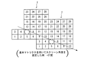
FIG. 6 shows an example in which another
上記のように複数の基本マトリクス2を並べて配置した構成では、同じ成長順番の番号の位置同士を結ぶ直線からなる中心軸によりスクリーン角度が決定される。図6の構成の場合、スクリーン角度は−27度となる。
In the configuration in which the plurality of
なお、図7に示すように、1個の基本マトリクス2を基準とし、この基本マトリクス2に対して、他の2個の基本マトリクス2を互いに異なる方向に配置した場合、上記中心軸4として中心軸4a,4bが生じる。本実施の形態では、一方の中心軸4aによりスクリーン角度を決定している。また、基本マトリクス2の形状、および基本マトリクス2内の各画素対応位置に設定されたドットの成長順番によって、スクリーン線数やスクリーン角度が決定される。本実施の形態では、スクリーン角度が−27度となる状態で多数の基本マトリクス2を配置することにより、図4に示すディザマトリクス1を構成している。
As shown in FIG. 7, when one
次に、ディザマトリクス1における各基本マトリクス2の選択順番の設定方法について説明する。
Next, a method for setting the selection order of each
上記のように、ディザマトリクス1には、各基本マトリクス2毎に選択順番が設定されている。この選択順番の設定はブルーノイズパターン(ブルーノイズマスク3)を利用して行われている。
As described above, the selection order is set for each
ここで、ブルーノイズとは、人間の目では知覚し難い空間周波数を有するパターンデータである。人間の視覚は、ある空間周波数以上ではほとんど感度がなく、視覚系のMTF(Modulation Transfer Function)は、一種の低域フィルタであることが知られている(例えば蒔田 剛,”インクジェットプリンタにおける高画質化技術”,日本画像学会誌,2001年,第40巻,第3号,p.239−243を参照)。擬似的なランダムパターンを操作し、その空間周波数の主要成分が視覚系MTFのカットオフ周波数以上の帯域に分布するパターンを生成すれば、ブルーノイズが得られる。ブルーノイズは、通常、256×256画素のデータマトリクスとして与えられ、前記データマトリクスはブルーノイズマスクと呼ばれている。 Here, the blue noise is pattern data having a spatial frequency that is difficult for human eyes to perceive. Human vision is almost insensitive above a certain spatial frequency, and the MTF (Modulation Transfer Function) of the visual system is known as a kind of low-pass filter (for example, Tsuyoshi Hamada, “High image quality in inkjet printers”). Technology ", Journal of the Imaging Society of Japan, 2001, Vol. 40, No. 3, p.239-243). Blue noise can be obtained by manipulating a pseudo-random pattern and generating a pattern in which the main component of the spatial frequency is distributed in a band equal to or higher than the cutoff frequency of the visual system MTF. The blue noise is usually given as a data matrix of 256 × 256 pixels, and the data matrix is called a blue noise mask.
図8は、ディザマトリクス1内の各基本マトリクス2の選択順番を設定する際に使用するブルーノイズマスク3の一例を示す説明図である。同図に示すブルーノイズマスク3は、128×128画素サイズにて発生させたブルーノイズ特性のパターンを有するものであり、最小値1から最大値255までの値に正規化した値が設定されている。
FIG. 8 is an explanatory diagram showing an example of the
ここでの処理は、ディザマトリクス1の各基本マトリクス2に対して、上記ブルーノイズマスク3の正規化されたブルーノイズデータを、ディザマトリクス1の形状に合うような形で選択して割り当てるものである。このように、ブルーノイズデータの小さい値から大きい値をディザマトリクス1の基本マトリクス2に順次対応させることにより、ブルーノイズ特性をほぼ維持した状態で、各基本マトリクス2の選択順番を設定することができる。
In this process, the normalized blue noise data of the
ここでは、ディザマトリクス1に対応するものであって、各基本マトリクス2の選択順番の設定前のものをスーパーマトリクスとして説明する。図9は、ディザマトリクス1を作成するためのスーパーマトリクス6を示す説明図である。
Here, the matrix corresponding to the
各基本マトリクス2の選択順番を設定する際には、図9に示すように、スーパーマトリクス6において、上記スクリーン角度を決定するために中心軸4を設定する。なお、図9のスーパーマトリクス6の場合、スクリーン角度は、前述のように、−27度となる。
When setting the selection order of each
次に、中心軸4に対して交差する方向(ほぼ線対称となる方向)を定め、この方向に設定される複数の交差軸5上に基本マトリクス2がいくつ存在するかを交差軸5毎に計算する。さらに、スーパーマトリクス6に含まれる基本マトリクス2の総数を求める。この場合、図9に示すように、上記中心軸4と交差する一方向への基本マトリクス2の列毎に、これら列方向に中心軸4に対する交差軸5を設定する。そして、これら交差軸5上に存在する基本マトリクス2の数を各交差軸5について中心軸4の両側の各側毎に算出する。
Next, a direction intersecting with the central axis 4 (a direction that is substantially line symmetric) is determined, and how many
図9の例では、中心軸4に対して、交差軸5−1から交差軸5−23まで選択され、交差軸5毎に基本マトリクス2がいくつ存在するか計算される。基本マトリクス2数の計算結果は、例えば、
交差軸5−1:2個(軸上:1、軸より上:1)
交差軸5−2:3個(軸上:1、軸より下:1、軸より上:1)
交差軸5−3:4個(軸上:1、軸より下:1、軸より上:2)
交差軸5−4:5個(軸上:1、軸より下:2、軸より上:2)
・
・
交差軸5−23:2個(軸上:0、軸より下:2)
となる。
In the example of FIG. 9, the cross axis 5-1 to the cross axis 5-23 are selected for the
Cross axis 5-1: 2 (on axis: 1, above axis: 1)
Cross axis 5-2: 3 (on axis: 1, below axis: 1, above axis: 1)
Cross axis 5-3: 4 (on axis: 1, below axis: 1, above axis: 2)
Cross axis 5-4: 5 (on axis: 1, below axis: 2, above axis: 2)
・
・
Cross axis 5-23: 2 (on axis: 0, below axis: 2)
It becomes.
このようにして計算された交差軸5毎の基本マトリクス2数に基づいて、スーパーマトリクス6に対応する、ブルーノイズマスク3のブルーノイズデータの範囲を決定する。具体的には、図10に示すように、スーパーマトリクス6にブルーノイズマスク3を対応させる場合、スーパーマトリクス6の中心軸4がブルーノイズマスク3におけるブルーノイズデータの垂直方向の並びに一致するようにスーパーマトリクス6を回転させ、中心軸4の左右の基本マトリクス2数に基づいて、スーパーマトリクス6に対応するブルーノイズデータの範囲を決定する。この場合、交差軸5については、スーパーマトリクス6自体を固定状態のまま回転させて、ブルーノイズマスク3におけるブルーノイズデータの水平方向の並びに一致させる。
The range of the blue noise data of the
上記のような処理を行う理由は次のとおりである。すなわち、ある一定のスクリーン角度を持ったスーパーマトリクス6では形状が歪形になる。したがって、水平方向および垂直方向に並んでいるブルーノイズデータをスーパーマトリクス6に対応させる場合には、スーパーマトリクス6の中心軸4をブルーノイズデータの垂直方向の並びに一致させる。これにより、スーパーマトリクス6にブルーノイズデータを対応させた場合に、スーパーマトリクス6(ディザマトリクス1)においてブルーノイズ特性を維持することができる。なお、スーパーマトリクス6に対応させるブルーノイズマスク3内の位置(ブルーノイズデータの範囲)は、上記規則に従えば、どの位置(範囲)を選択しても良い。言い換えると、スーパーマトリクス6に対応させるブルーノイズマスク3内の位置は、ブルーノイズマスク3内におけるスーパーマトリクス6の形状を維持した状態にて、移動させることができる。
The reason why the above processing is performed is as follows. That is, the shape of the
前述のように、スーパーマトリクス6に設定された中心軸(基本軸、垂直軸)4を中心として中心軸4の左右方向において必要となる基本マトリクス2の個数は予め求まっている。したがって、上記のようにスーパーマトリクス6をブルーノイズマスク3に適合させる処理により、ブルーノイズマスク3の正規化されたブルーノイズデータに対して、基本マトリクス2の数に応じて対象となる範囲を選択することができる。図10ではその範囲を実線の太線にて示している。
As described above, the number of
次に、図10に示す選択された範囲のブルーノイズデータをスーパーマトリクス6内の基本マトリクス2の数を最大値として再設定する。すなわち、1から255までの順番に配置されていたブルーノイズデータをスーパーマトリクス6の範囲内において同じデータが存在しないように、1から175までのデータに並び替える。
Next, the blue noise data in the selected range shown in FIG. 10 is reset with the number of
具体的には、本実施の形態において、スーパーマトリクス6内の基本マトリクス2の数は175個となっている。したがって、ブルーノイズマスク3におけるスーパーマトリクス6の範囲内において、1と表示されているブルーノイズデータが1個のみ存在していれば、その位置の基本マトリクス2の選択順番は1とする。一方、他に1と表示されているブルーノイズデータが存在すれば、それらの位置の基本マトリクス2の選択順番は何れか一方が1、他方が2となる。次に、2と表示されているブルーノイズデータがあれば、先に1と2が設定されているので、その位置の基本マトリクス2の選択順番は3となる。このようにして、同じデータ(同じ選択順番)が重ならないように、各ブルーノイズデータの位置の基本マトリクス2の選択順番を最大値の175まで設定する。
Specifically, in the present embodiment, the number of
上記のような処理により、スーパーマトリクス6内の基本マトリクス2に対して、1から最大個数の175までの選択順番が設定される。このようにして作成されたディザマトリクス1では、基本マトリクス2内の、入力画像データの各画素に対応する位置のドット成長順番と各基本マトリクス2の選択順番との相互関係により、ディザマトリクス1全体として入力画像データに対する画素対応位置の成長順番、すなわち入力画像データの各画素の処理順番(出力画像データの各画素の成長順番)が一つに定まる。
With the above processing, the selection order from 1 to the
具体的には、ディザマトリクス1内での選択順番が1に設定されている基本マトリクス2内の1番目の位置(1番目の位置に対応する画素)に最初にドットが打たれ、次に、ディザマトリクス1内での選択順番が2に設定されている基本マトリクス2内の1番目の位置(1番目の位置に対応する画素)にドットが打たれる。以後同様にして、ディザマトリクス1内での選択順番が175に設定されている基本マトリクス2内の1番目の位置(1番目の位置に対応する画素)の処理まで進む。次に、ディザマトリクス1内での選択順番が1に設定されている基本マトリクス2内の2番目の位置(2番目の位置に対応する画素)にドットが打たれ、以降、ディザマトリクス1の各位置に対応する、入力画像データの各画素の全部に対する処理が進み、この入力画像データの各画素に対応する出力画像データの各画素が埋まるようにドットが順次成長していく。
Specifically, a dot is first placed at the first position (pixel corresponding to the first position) in the
本実施の形態のカラー画像処理装置10は、上記のようにしてディザマトリクス1を作成するために、図11に示すディザマトリクス作成装置100を備えている。このディザマトリクス作成装置100は、例えば階調再現処理部19に備えられていてもよい。ディザマトリクス作成装置100は、図11に示すように、スーパーマトリクス作成部(第2マトリクス作成部)101、中心軸設定部102、基本マトリクス数算出部(第1マトリクス数算出部)103、ブルーノイズマスク適用部104および選択順序設定部105を備えている。
The color
上記ディザマトリクス作成装置100によるディザマトリクス1の作成動作の詳細は前述のとおりである。その作成動作をフローチャートに示すと図12のとおりである。このフローチャートに従って、ディザマトリクス1の作成動作をまとめると以下のとおりである。
The details of the operation of creating the
先ず、スーパーマトリクス作成部101は、入力画像データの各画素に対応する位置である画素対応位置毎にドットの出力順番が定められている基本マトリクス2(第1マトリクス)を用意する。次に、スーパーマトリクス作成部101は、上記基本マトリクス2が複数並べて配置されたスーパーマトリクス6(第2マトリクス)を作成する(S21:スーパーマトリクス作成工程(第2マトリクス作成工程))。
First, the super
次に、中心軸設定部102は、スーパーマトリクス6のスクリーン角を求め、そのスクリーン角に従って、基本マトリクス2の一方向への並び方向に一つの中心軸4を設定する(S22:中心軸設定工程)。
Next, the central
次に、基本マトリクス数算出部103は、前記中心軸4と交差する方向への基本マトリクス2の列毎に、これら列方向に前記中心軸4に対する交差軸5を設定する。次に、これら交差軸5上に存在する基本マトリクス2の数を各交差軸5について前記中心軸4の両側の各側毎に第1の算出結果として算出する。さらに、スーパーマトリクス6内の基本マトリクス2の総数を第2の算出結果として算出する(S23:基本マトリクス数算出工程(第1マトリクス数算出工程))。
Next, the basic matrix
次に、ブルーノイズマスク適用部104は、スーパーマトリクス6の中心軸4をブルーノイズマスクの垂直方向に一致させ、かつスーパーマトリクス6の交差軸5をブルーノイズマスクの水平方向に一致させ、基本マトリクス数算出部103の第1の算出結果から、スーパーマトリクス6の各基本マトリクス2に対応するブルーノイズマスクの各ブルーノイズデータを求める(S24:ブルーノイズマスク適用工程)。
Next, the blue noise
次に、選択順序設定部105は、各ブルーノイズデータに設定されているドットの出力順番をスーパーマトリクス6における各基本マトリクス2の選択順番とする。次に、選択順序設定部105は、基本マトリクス数算出部103の第2の算出結果が示す基本マトリクス2の総数値が前記選択順番の最終の順番値となるように、前記選択順番を並び替える(S25:選択順番設定工程)。
Next, the selection
上記のように、本実施の形態のディザマトリクス1の作成方法においては、先ず、図5に示すように、画素対応位置にドットの成長順番が設定されている基本マトリクス2を歪形に設計し、次に、図6および図4に示すように、基本マトリクス2を並べて配置してスクリーン角度を有するスーパーマトリクス6を作成し、その後、このスーパーマトリクス6の各基本マトリクス2に対して、各基本マトリクス2同士での処理順番(ドット成長順番)を示す選択順番を設定している。
As described above, in the method of creating the
このようなディザマトリクス1を使用する実際の中間調処理においては、ディザマトリクス1のマトリクスデータを展開して、例えば、70×70画素に対応する矩形サイズとし、上記マトリクスデータが中間調処理の閾値データとして設定される。これにより、ディザマトリクス1の各画素対応位置のデータは、2値レベル出力用のディザマトリクスデータ、すなわち閾値として機能する。
In actual halftone processing using such a
具体的には、上記ディザマトリクスデータ(閾値)は、カラー画像処理装置10が備える図2に示した階調再現処理部19の閾値出力値格納部52に格納され、階調再現処理部19でのディザ処理では、閾値処理部51において入力画像データの画素値と上記閾値とを比較し、この比較結果に応じて所定の出力値(画素値)が出力される。
Specifically, the dither matrix data (threshold value) is stored in the threshold output
上記のように、2値出力用のディザマトリクス1(ディザスクリーン)にスーパーマトリクス6を適用する場合、スーパーマトリクス6内に一定の中心軸4を設定し、この中心軸4をブルーノイズデータの並び方向(例えばブルーノイズデータの垂直並び方向)に合致させ、かつスーパーマトリクス6の形状に合う範囲のブルーノイズデータを選択してスーパーマトリクス6のデータとしている。これにより、スクリーン角度を設定した歪形のディザマトリクス1(スーパーマトリクス6)においても、基本マトリクス2のドット成長順番(選択順番)がブルーノイズの成長順番に近くなる。この結果、ディザマトリクス1にてディザ処理された出力画像データは、特に、ハイライト部分での再現性が良好になる。
As described above, when the
また、本実施の形態において、ディザマトリクス1(スーパーマトリクス6)のサイズは、例えば70×70画素に対応するサイズであり、ブルーノイズマスク3のサイズは、ディザマトリクス1(スーパーマトリクス6)のサイズよりも大きく、例えば128×128画素に対応するサイズである。したがって、スーパーマトリクス6に対応する、ブルーノイズマスク3のブルーノイズデータを決定する場合に、スーパーマトリクス6に対応するブルーノイズデータの範囲は、その範囲をブルーノイズマスク3内で移動させることにより、容易に変更可能である。
In the present embodiment, the size of the dither matrix 1 (super matrix 6) is a size corresponding to, for example, 70 × 70 pixels, and the size of the
スーパーマトリクス6に対応するブルーノイズデータの範囲を変更する操作は、例えば操作パネル41からの入力操作によって行うことができる。この場合、ブルーノイズマスク適用部104は、操作パネル41からの例えば上記範囲の変更入力に基づいて、スーパーマトリクス6に対応するブルーノイズデータの範囲を移動させる。
The operation of changing the range of the blue noise data corresponding to the
例えば、スーパーマトリクス6にブルーノイズデータを対応させて基本マトリクス2の選択順番を決定し、ディザマトリクス1を作成した場合、そのディザマトリクス1によりディザ処理を行った結果、出力画像データにおいてドットが偏る場合がある。このような場合には、スーパーマトリクス6に対応するブルーノイズデータの範囲を変更することが有効である。この場合の処理を図13に示す。図13は、ブルーノイズマスク3上において、スーパーマトリクス6に対応するブルーノイズデータの範囲を移動させる処理の説明図である。
For example, when the selection order of the
図13では、スーパーマトリクス6に対応するブルーノイズデータの最初に設定した範囲を実線の太線にて示し、移動後の範囲を二点鎖線の太線にて示している。移動後の範囲は、最初に設定した範囲に対して、X方向に20画素、Y方向に13画素シフトしている。このように、スーパーマトリクス6に対応するブルーノイズデータの範囲を適宜移動させることにより、ブルーノイズの特性を維持しながら基本マトリクス2の選択順番を変更でき、良好な出力画像データを出力できるディザマトリクス1を得ることができる。
In FIG. 13, the initially set range of the blue noise data corresponding to the
なお、上記ディザマトリクス1によりディザ処理を行う階調再現処理部19を備えたカラー画像処理装置10は、ソフトウエア(アプリケーションプログラム)として実現してもかまわない。この場合、ディザ処理を実現するソフトウエアを組み込んだプリンタ・ドライバをコンピュータに設けることができる。
The color
図14に示すように、コンピュータ200には、プリンタ・ドライバ201、通信ポートドライバ202および通信ポート(例えばRS232C・LAN等)203が組み込まれている。プリンタ・ドライバ201は、色補正部15、黒生成下色除去部16、階調再現処理部19およびプリンタ言語翻訳部31を有している。
As illustrated in FIG. 14, a
また、コンピュータ200は、プリンタ(画像出力装置)204と接続されている。プリンタ204は、コンピュータ200から出力された画像データに基づいて印刷を行うようになっている。プリンタ204は、プリンタ機能の他に、コピー機能およびファックス機能を有するデジタル複合機であってもよい。
The
例えばコンピュータ200において各種のアプリケーションプログラムを実行することにより生成された画像データは、色補正部15、黒生成下色除去部16および階調再現処理部19において先述のように処理される。これら各部の処理を経た画像データは、プリンタ言語翻訳部31にてプリンタ言語に変換され、通信ポートドライバ202および通信ポート203を介してプリンタ204に入力され、用紙上に印刷される。
For example, image data generated by executing various application programs in the
本発明の実施の形態に示したカラー画像処理装置10、プリンタ・ドライバ201およびディザマトリクス作成装置100の各ブロックは、ハードウェアロジックによって構成してもよいし、次のようにCPUを用いてソフトウェアによって実現してもよい。
Each block of the color
すなわち、上記各装置は、各機能を実現する制御プログラムの命令を実行するCPU(central processing unit)、上記プログラムを格納したROM(read only memory)、上記プログラムを展開するRAM(random access memory)、上記プログラムおよび各種データを格納するメモリ等の記憶装置(記録媒体)などを備えている。そして、本発明の目的は、上述した機能を実現するソフトウェアである上記各装置の制御プログラムのプログラムコード(実行形式プログラム、中間コードプログラム、ソースプログラム)をコンピュータで読み取り可能に記録した記録媒体を、上記各装置に供給し、そのコンピュータ(またはCPUやMPU)が記録媒体に記録されているプログラムコードを読み出し実行することによっても、達成可能である。 That is, each device includes a CPU (central processing unit) that executes instructions of a control program that realizes each function, a ROM (read only memory) that stores the program, a RAM (random access memory) that expands the program, A storage device (recording medium) such as a memory for storing the program and various data is provided. An object of the present invention is to provide a recording medium in which a program code (execution format program, intermediate code program, source program) of a control program for each of the above devices, which is software that realizes the above-described functions, is recorded in a computer-readable manner This can also be achieved by supplying each of the above devices and reading and executing the program code recorded on the recording medium by the computer (or CPU or MPU).
上記記録媒体としては、例えば、磁気テープやカセットテープ等のテープ系、フロッピー(登録商標)ディスク/ハードディスク等の磁気ディスクやCD−ROM/MO/MD/DVD/CD−R等の光ディスクを含むディスク系、ICカード(メモリカードを含む)/光カード等のカード系、あるいはマスクROM/EPROM/EEPROM/フラッシュROM等の半導体メモリ系などを用いることができる。 Examples of the recording medium include a tape system such as a magnetic tape and a cassette tape, a magnetic disk such as a floppy (registered trademark) disk / hard disk, and an optical disk such as a CD-ROM / MO / MD / DVD / CD-R. Card system such as IC card, IC card (including memory card) / optical card, or semiconductor memory system such as mask ROM / EPROM / EEPROM / flash ROM.
また、上記各装置を通信ネットワークと接続可能に構成し、上記プログラムコードを通信ネットワークを介して供給してもよい。この通信ネットワークとしては、特に限定されず、例えば、インターネット、イントラネット、エキストラネット、LAN、ISDN、VAN、CATV通信網、仮想専用網(virtual private network)、電話回線網、移動体通信網、衛星通信網等が利用可能である。また、通信ネットワークを構成する伝送媒体としては、特に限定されず、例えば、IEEE1394、USB、電力線搬送、ケーブルTV回線、電話線、ADSL回線等の有線でも、IrDAやリモコンのような赤外線、Bluetooth(登録商標)、802.11無線、HDR、携帯電話網、衛星回線、地上波デジタル網等の無線でも利用可能である。なお、本発明は、上記プログラムコードが電子的な伝送で具現化された、搬送波に埋め込まれたコンピュータデータ信号の形態でも実現され得る。 Further, each of the above devices may be configured to be connectable to a communication network, and the program code may be supplied via the communication network. The communication network is not particularly limited. For example, the Internet, intranet, extranet, LAN, ISDN, VAN, CATV communication network, virtual private network, telephone line network, mobile communication network, satellite communication. A net or the like is available. Also, the transmission medium constituting the communication network is not particularly limited. For example, even in the case of wired such as IEEE 1394, USB, power line carrier, cable TV line, telephone line, ADSL line, etc., infrared rays such as IrDA and remote control, Bluetooth ( (Registered trademark), 802.11 wireless, HDR, mobile phone network, satellite line, terrestrial digital network, and the like can also be used. The present invention can also be realized in the form of a computer data signal embedded in a carrier wave in which the program code is embodied by electronic transmission.
本発明は上述した実施形態に限定されるものではなく、請求項に示した範囲で種々の変更が可能である。すなわち、請求項に示した範囲で適宜変更した技術的手段を組み合わせて得られる実施形態についても本発明の技術的範囲に含まれる。 The present invention is not limited to the above-described embodiments, and various modifications can be made within the scope shown in the claims. That is, embodiments obtained by combining technical means appropriately modified within the scope of the claims are also included in the technical scope of the present invention.
10 カラー画像処理装置
19 階調再現処理部
20 カラー画像入力装置
30 カラー画像出力装置
51 閾値処理部
52 閾値出力値格納部
100 ディザマトリクス作成装置
101 スーパーマトリクス作成部(第2マトリクス作成部)
102 中心軸設定部
103 基本マトリクス数算出部(第1マトリクス数算出部)
104 ブルーノイズマスク適用部
105 選択順序設定部
200 コンピュータ
201 プリンタ・ドライバ
DESCRIPTION OF
102 Central
104 Blue Noise
Claims (8)
入力画像データの各画素に対応する位置である画素対応位置毎にドットの出力順番が定められている第1マトリクスを使用し、この第1マトリクスが複数並べて配置された第2マトリクスを作成する第2マトリクス作成工程と、
前記第2マトリクスのスクリーン角に従って、複数個の前記第1マトリクスの一方向への並び方向に一つの中心軸を設定する中心軸設定工程と、
前記中心軸と交差する方向への前記第1マトリクスの列毎に、これら列方向に前記中心軸に対する交差軸を設定し、これら交差軸上に存在する前記第1マトリクスの数を前記の各交差軸について前記中心軸の両側の各側毎に算出して第1の算出結果を得るとともに、前記第2マトリクス内の前記第1マトリクスの総数を第2の算出結果として得る第1マトリクス数算出工程と、
前記第2マトリクスの前記中心軸をブルーノイズマスクの垂直方向に一致させ、かつ前記第2マトリクスの前記交差軸を前記ブルーノイズマスクの水平方向に一致させ、前記第1マトリクス数算出工程の前記第1の算出結果から、前記第2マトリクスに対応するブルーノイズマスクの範囲を決定し、前記第2マトリクスの各第1マトリクスに対応するブルーノイズデータを求めるブルーノイズマスク適用工程と、
前記の各ブルーノイズデータに設定されているドットの出力順番を前記の各第1マトリクスの選択順番とし、前記第1マトリクス数算出工程の前記第2の算出結果が示す前記第1マトリクスの総数値が前記選択順番の最終の順番値となるように、前記選択順番を並び替える選択順番設定工程とを備えていることを特徴とするディザマトリクスの作成方法。 In a method of creating a dither matrix for performing binary dither processing as gradation reproduction processing on input image data,
A first matrix in which a dot output order is determined for each pixel corresponding position that is a position corresponding to each pixel of the input image data is used to create a second matrix in which a plurality of the first matrices are arranged. 2 matrix creation process;
A central axis setting step of setting one central axis in a direction in which the plurality of first matrices are arranged in one direction according to the screen angle of the second matrix;
For each column of the first matrix in a direction crossing the central axis, an axis of intersection with respect to the central axis is set in the column direction, and the number of the first matrix existing on the crossing axis is set to each of the intersections. A first matrix number calculating step of obtaining a first calculation result by calculating for each side of both sides of the central axis with respect to the axis, and obtaining a total number of the first matrix in the second matrix as a second calculation result When,
The central axis of the second matrix is made to coincide with the vertical direction of the blue noise mask, and the intersecting axis of the second matrix is made to coincide with the horizontal direction of the blue noise mask, so that the first matrix number calculating step A blue noise mask applying step of determining a blue noise mask range corresponding to the second matrix from the calculation result of 1, and obtaining blue noise data corresponding to each first matrix of the second matrix;
The output order of the dots set in each blue noise data is set as the selection order of each first matrix, and the total value of the first matrix indicated by the second calculation result of the first matrix number calculation step And a selection order setting step of rearranging the selection order so that the value becomes the final order value of the selection order.
入力画像データの各画素に対応する位置である画素対応位置毎にドットの出力順番が定められている第1マトリクスを使用し、この第1マトリクスが複数並べて配置された第2マトリクスを作成する第2マトリクス作成部と、
前記第2マトリクスのスクリーン角に従って、複数個の前記第1マトリクスの一方向への並び方向に一つの中心軸を設定する中心軸設定部と、
前記中心軸と交差する方向への前記第1マトリクスの列毎に、これら列方向に前記中心軸に対する交差軸を設定し、これら交差軸上に存在する前記第1マトリクスの数を前記の各交差軸について前記中心軸の両側の各側毎に算出して第1の算出結果を得るとともに、前記第2マトリクス内の前記第1マトリクスの総数を第2の算出結果として得る第1マトリクス数算出部と、
前記第2マトリクスの前記中心軸をブルーノイズマスクの垂直方向に一致させ、かつ前記第2マトリクスの前記交差軸を前記ブルーノイズマスクの水平方向に一致させ、前記第1マトリクス数算出部による前記第1の算出結果から、前記第2マトリクスに対応するブルーノイズマスクの範囲を決定し、前記第2マトリクスの各第1マトリクスに対応するブルーノイズデータを求めるブルーノイズマスク適用部と、
前記の各ブルーノイズデータに設定されているドットの出力順番を前記の各第1マトリクスの選択順番とし、前記第1マトリクス数算出部による前記第2の算出結果が示す前記第1マトリクスの総数値が前記選択順番の最終の順番値となるように、前記選択順番を並び替える選択順番設定部とを備えていることを特徴とするディザマトリクスの作成装置。 In a dither matrix creating apparatus for creating a dither matrix for performing binary dither processing as tone reproduction processing on input image data,
A first matrix in which a dot output order is determined for each pixel corresponding position that is a position corresponding to each pixel of the input image data is used to create a second matrix in which a plurality of the first matrices are arranged. 2 matrix creation part;
A central axis setting unit that sets one central axis in a direction in which the first matrix is aligned in one direction according to the screen angle of the second matrix;
For each column of the first matrix in a direction crossing the central axis, an axis of intersection with respect to the central axis is set in the column direction, and the number of the first matrix existing on the crossing axis is set to each of the intersections. A first matrix number calculation unit that obtains a first calculation result by calculating for each side on both sides of the central axis with respect to the axis, and that obtains a total number of the first matrix in the second matrix as a second calculation result When,
The central axis of the second matrix is made to coincide with a vertical direction of a blue noise mask, and the intersecting axis of the second matrix is made to coincide with a horizontal direction of the blue noise mask. A blue noise mask applying unit that determines a blue noise mask range corresponding to the second matrix from the calculation result of 1, and obtains blue noise data corresponding to each first matrix of the second matrix;
The output order of the dots set in each blue noise data is set as the selection order of each first matrix, and the total value of the first matrix indicated by the second calculation result by the first matrix number calculation unit And a selection order setting unit for rearranging the selection order so that the value becomes the final order value of the selection order.
Priority Applications (1)
| Application Number | Priority Date | Filing Date | Title |
|---|---|---|---|
| JP2008266499A JP4987833B2 (en) | 2008-10-15 | 2008-10-15 | Dither matrix creation method, dither matrix creation device, image processing device, image forming device, program, and recording medium |
Applications Claiming Priority (1)
| Application Number | Priority Date | Filing Date | Title |
|---|---|---|---|
| JP2008266499A JP4987833B2 (en) | 2008-10-15 | 2008-10-15 | Dither matrix creation method, dither matrix creation device, image processing device, image forming device, program, and recording medium |
Publications (2)
| Publication Number | Publication Date |
|---|---|
| JP2010098448A JP2010098448A (en) | 2010-04-30 |
| JP4987833B2 true JP4987833B2 (en) | 2012-07-25 |
Family
ID=42259838
Family Applications (1)
| Application Number | Title | Priority Date | Filing Date |
|---|---|---|---|
| JP2008266499A Active JP4987833B2 (en) | 2008-10-15 | 2008-10-15 | Dither matrix creation method, dither matrix creation device, image processing device, image forming device, program, and recording medium |
Country Status (1)
| Country | Link |
|---|---|
| JP (1) | JP4987833B2 (en) |
Family Cites Families (4)
| Publication number | Priority date | Publication date | Assignee | Title |
|---|---|---|---|---|
| JP4204000B2 (en) * | 2003-12-02 | 2009-01-07 | 株式会社リコー | Dither matrix creation method and apparatus, image processing method and apparatus, image forming method and apparatus, program, and recording medium |
| JP4057515B2 (en) * | 2003-12-11 | 2008-03-05 | 株式会社リコー | Dither matrix basic matrix generation method, dither matrix generation method, computer program for executing dither matrix generation method, dither matrix generation device, image processing method, image forming method, image processing device, and image forming device |
| JP4545128B2 (en) * | 2006-09-16 | 2010-09-15 | 株式会社リコー | Image processing apparatus, program, image forming apparatus, image forming method, dither matrix |
| JP4598750B2 (en) * | 2006-12-27 | 2010-12-15 | セイコーエプソン株式会社 | Dither matrix generation |
-
2008
- 2008-10-15 JP JP2008266499A patent/JP4987833B2/en active Active
Also Published As
| Publication number | Publication date |
|---|---|
| JP2010098448A (en) | 2010-04-30 |
Similar Documents
| Publication | Publication Date | Title |
|---|---|---|
| JP4610802B2 (en) | Gray level image edge enhancement | |
| JP4173154B2 (en) | Image processing method, image processing apparatus, image forming apparatus, computer program, and recording medium | |
| JP2002112026A (en) | Processor and method for improving edge by setting adjustable threshold | |
| JPH04336870A (en) | Color picture recorder | |
| JP5095667B2 (en) | Output instruction apparatus, image forming system, output instruction method, control program, and recording medium therefor | |
| JP4342560B2 (en) | Image processing method, image processing apparatus, computer program, and recording medium | |
| US6721062B1 (en) | Color image processing apparatus using pulse width modulation | |
| US20030123093A1 (en) | Processor for image processing, method of processing image using the same, and printer incorporating the same | |
| JP2010278933A (en) | Image processing device, image forming device, image processing method, program and recording medium | |
| JP4987833B2 (en) | Dither matrix creation method, dither matrix creation device, image processing device, image forming device, program, and recording medium | |
| JP4034061B2 (en) | Image processing method, image processing apparatus, image forming apparatus, image processing program, and computer-readable recording medium | |
| JP5079904B2 (en) | Multilevel dither processing method, image processing apparatus, image forming apparatus, multi-function machine, multilevel dither processing program, and computer-readable recording medium | |
| JP2005072635A (en) | Image processing apparatus, image forming apparatus, image reading apparatus, image processing method, image processing program, and computer-readable recording medium stored with the image processing program | |
| JP4991782B2 (en) | Image processing apparatus, image forming apparatus, image processing method, image processing program, and recording medium | |
| JP2001018455A (en) | Apparatus for processing gradation image | |
| JP4499685B2 (en) | Image processing apparatus, image forming apparatus including the same, image processing method, image processing program, and recording medium | |
| JP4176656B2 (en) | Image processing apparatus, image processing method, image forming apparatus, image processing program, and recording medium recording the program | |
| JP2006005907A (en) | Image processing method, image processing apparatus, image forming apparatus, computer program and dummy halftone matrix creating method | |
| JP2006033643A (en) | Image processing apparatus, image forming apparatus, image processing method, and computer program | |
| JP2009044267A (en) | Multi-value dither processing method, image processing apparatus, image forming apparatus, composite machine, multi-value dither processing program and computer-readable recording medium | |
| JP4139752B2 (en) | Image processing apparatus, image forming apparatus, image processing method, image processing program, and recording medium recording the program | |
| JP2004312250A (en) | Image processing apparatus and image forming apparatus | |
| JP2007334520A (en) | Image processor, image forming device, image processing method, image processing program, and recording medium recoding image processing program | |
| JP2009188453A (en) | Gradation setting method for dither matrix, image processing method, image processing apparatus, image forming apparatus, program and recording medium | |
| JP2009296460A (en) | Image processing method, image processing device, image forming apparatus, program and recording medium |
Legal Events
| Date | Code | Title | Description |
|---|---|---|---|
| A621 | Written request for application examination |
Free format text: JAPANESE INTERMEDIATE CODE: A621 Effective date: 20110223 |
|
| TRDD | Decision of grant or rejection written | ||
| A01 | Written decision to grant a patent or to grant a registration (utility model) |
Free format text: JAPANESE INTERMEDIATE CODE: A01 Effective date: 20120327 |
|
| A01 | Written decision to grant a patent or to grant a registration (utility model) |
Free format text: JAPANESE INTERMEDIATE CODE: A01 |
|
| A61 | First payment of annual fees (during grant procedure) |
Free format text: JAPANESE INTERMEDIATE CODE: A61 Effective date: 20120425 |
|
| R150 | Certificate of patent or registration of utility model |
Free format text: JAPANESE INTERMEDIATE CODE: R150 Ref document number: 4987833 Country of ref document: JP Free format text: JAPANESE INTERMEDIATE CODE: R150 |
|
| FPAY | Renewal fee payment (event date is renewal date of database) |
Free format text: PAYMENT UNTIL: 20150511 Year of fee payment: 3 |