JP4987775B2 - Wireless powered terminal, system and method - Google Patents
Wireless powered terminal, system and method Download PDFInfo
- Publication number
- JP4987775B2 JP4987775B2 JP2008083432A JP2008083432A JP4987775B2 JP 4987775 B2 JP4987775 B2 JP 4987775B2 JP 2008083432 A JP2008083432 A JP 2008083432A JP 2008083432 A JP2008083432 A JP 2008083432A JP 4987775 B2 JP4987775 B2 JP 4987775B2
- Authority
- JP
- Japan
- Prior art keywords
- terminal
- frequency
- microwave
- receiving
- information
- Prior art date
- Legal status (The legal status is an assumption and is not a legal conclusion. Google has not performed a legal analysis and makes no representation as to the accuracy of the status listed.)
- Active
Links
- 238000000034 method Methods 0.000 title claims description 18
- 230000005540 biological transmission Effects 0.000 claims description 96
- 238000004891 communication Methods 0.000 claims description 62
- 238000005259 measurement Methods 0.000 claims description 20
- 238000006243 chemical reaction Methods 0.000 claims description 9
- 238000001514 detection method Methods 0.000 description 15
- 238000010586 diagram Methods 0.000 description 6
- 230000001149 cognitive effect Effects 0.000 description 4
- 230000005674 electromagnetic induction Effects 0.000 description 4
- 239000000470 constituent Substances 0.000 description 2
- 238000005516 engineering process Methods 0.000 description 2
- 238000011835 investigation Methods 0.000 description 2
- 238000007796 conventional method Methods 0.000 description 1
- 230000008878 coupling Effects 0.000 description 1
- 238000010168 coupling process Methods 0.000 description 1
- 238000005859 coupling reaction Methods 0.000 description 1
- 230000000694 effects Effects 0.000 description 1
- 238000003872 feeding technique Methods 0.000 description 1
- 238000000691 measurement method Methods 0.000 description 1
- 239000000126 substance Substances 0.000 description 1
Images


Classifications
-
- H—ELECTRICITY
- H04—ELECTRIC COMMUNICATION TECHNIQUE
- H04B—TRANSMISSION
- H04B5/00—Near-field transmission systems, e.g. inductive or capacitive transmission systems
-
- H—ELECTRICITY
- H02—GENERATION; CONVERSION OR DISTRIBUTION OF ELECTRIC POWER
- H02J—CIRCUIT ARRANGEMENTS OR SYSTEMS FOR SUPPLYING OR DISTRIBUTING ELECTRIC POWER; SYSTEMS FOR STORING ELECTRIC ENERGY
- H02J50/00—Circuit arrangements or systems for wireless supply or distribution of electric power
- H02J50/10—Circuit arrangements or systems for wireless supply or distribution of electric power using inductive coupling
- H02J50/12—Circuit arrangements or systems for wireless supply or distribution of electric power using inductive coupling of the resonant type
-
- H—ELECTRICITY
- H02—GENERATION; CONVERSION OR DISTRIBUTION OF ELECTRIC POWER
- H02J—CIRCUIT ARRANGEMENTS OR SYSTEMS FOR SUPPLYING OR DISTRIBUTING ELECTRIC POWER; SYSTEMS FOR STORING ELECTRIC ENERGY
- H02J50/00—Circuit arrangements or systems for wireless supply or distribution of electric power
- H02J50/20—Circuit arrangements or systems for wireless supply or distribution of electric power using microwaves or radio frequency waves
-
- H—ELECTRICITY
- H02—GENERATION; CONVERSION OR DISTRIBUTION OF ELECTRIC POWER
- H02J—CIRCUIT ARRANGEMENTS OR SYSTEMS FOR SUPPLYING OR DISTRIBUTING ELECTRIC POWER; SYSTEMS FOR STORING ELECTRIC ENERGY
- H02J50/00—Circuit arrangements or systems for wireless supply or distribution of electric power
- H02J50/80—Circuit arrangements or systems for wireless supply or distribution of electric power involving the exchange of data, concerning supply or distribution of electric power, between transmitting devices and receiving devices
-
- H—ELECTRICITY
- H02—GENERATION; CONVERSION OR DISTRIBUTION OF ELECTRIC POWER
- H02J—CIRCUIT ARRANGEMENTS OR SYSTEMS FOR SUPPLYING OR DISTRIBUTING ELECTRIC POWER; SYSTEMS FOR STORING ELECTRIC ENERGY
- H02J50/00—Circuit arrangements or systems for wireless supply or distribution of electric power
- H02J50/90—Circuit arrangements or systems for wireless supply or distribution of electric power involving detection or optimisation of position, e.g. alignment
-
- H—ELECTRICITY
- H04—ELECTRIC COMMUNICATION TECHNIQUE
- H04B—TRANSMISSION
- H04B5/00—Near-field transmission systems, e.g. inductive or capacitive transmission systems
- H04B5/20—Near-field transmission systems, e.g. inductive or capacitive transmission systems characterised by the transmission technique; characterised by the transmission medium
- H04B5/24—Inductive coupling
- H04B5/26—Inductive coupling using coils
-
- H—ELECTRICITY
- H04—ELECTRIC COMMUNICATION TECHNIQUE
- H04B—TRANSMISSION
- H04B5/00—Near-field transmission systems, e.g. inductive or capacitive transmission systems
- H04B5/70—Near-field transmission systems, e.g. inductive or capacitive transmission systems specially adapted for specific purposes
- H04B5/79—Near-field transmission systems, e.g. inductive or capacitive transmission systems specially adapted for specific purposes for data transfer in combination with power transfer
Landscapes
- Engineering & Computer Science (AREA)
- Computer Networks & Wireless Communication (AREA)
- Power Engineering (AREA)
- Signal Processing (AREA)
- Transceivers (AREA)
- Mobile Radio Communication Systems (AREA)
Description
この発明は、無線給電技術に関し、特に無線給電に利用する周波数の選択方法についての無線被給電端末、システムおよび方法に関する。 The present invention relates to a wireless power feeding technique, and more particularly to a wireless powered terminal, a system, and a method for selecting a frequency used for wireless power feeding.
無線給電用のマイクロ波送信部と無線通信手段とから構成されるマイクロ波送信端末と、電力を無線で受信する無線給電部と無線通信手段とから構成される被給電端末と、から構成される無線給電システムが知られている。このシステムを用いることで、情報の送受信と、エネルギーの無線給電(無線伝送)が可能となる(例えば、特許文献1参照)。 A microwave transmission terminal composed of a microwave transmission unit for wireless power feeding and wireless communication means, and a powered terminal composed of a wireless power feeding unit for wirelessly receiving power and wireless communication means Wireless power supply systems are known. By using this system, transmission / reception of information and wireless power feeding (wireless transmission) of energy are possible (for example, see Patent Document 1).
従来の無線給電システムにおいては、特定の周波数のマイクロ波を利用して無線給電をおこなっている。例えば2.4GHzのISM帯の周波数を利用した場合、無線LAN等の無線通信へ対して干渉となる問題がある。また、無線通信で使用することが可能な周波数は有限であり、既に無線通信用に大部分の周波数が割り当てられている。このために、無線給電のための周波数の確保が困難になっている。 In a conventional wireless power feeding system, wireless power feeding is performed using a microwave having a specific frequency. For example, when a 2.4 GHz ISM band frequency is used, there is a problem of interference with wireless communication such as a wireless LAN. In addition, the frequencies that can be used in wireless communication are limited, and most of the frequencies have already been allocated for wireless communication. For this reason, it is difficult to secure a frequency for wireless power feeding.
周波数の確保のために、コグニティブ無線技術が開発されている。コグニティブ無線通信では、既に割り当てられている周波数が利用されているか利用されていないかを検出して、利用されていない空き周波数を利用して無線通信を行なう。これにより、無線通信へ対しての干渉を削減することが可能となる。 Cognitive radio technology has been developed to ensure the frequency. In cognitive radio communication, it is detected whether an already allocated frequency is used or not, and radio communication is performed using an unused frequency. As a result, it is possible to reduce interference with wireless communication.
そこで、コグニティブ無線通信技術を無線給電に応用することが考えられる。ところが、空き周波数が複数存在した場合には、無線給電に対して最適な周波数を選択する必要があるが、従来この方法は示されていない。
このように従来の無線給電システムにおいては、特定の周波数のマイクロ波を利用して無線給電をおこなっているので、無線通信へ干渉となる場合がある。また、空き周波数を利用することも考えられるが、無線給電に対して最適な周波数の選択方法が課題となっている。 As described above, in the conventional wireless power feeding system, since wireless power feeding is performed using a microwave of a specific frequency, there is a case where it interferes with wireless communication. Although it is conceivable to use a vacant frequency, a method for selecting an optimum frequency for wireless power feeding has been an issue.
この発明は、上述した事情を考慮してなされたものであり、無線給電に最適な周波数を利用して無線給電を行うことが可能な無線被給電端末、システムおよびプログラムを提供することを目的とする。 The present invention has been made in consideration of the above-described circumstances, and an object of the present invention is to provide a wireless power-supplied terminal, a system, and a program capable of performing wireless power feeding using a frequency optimal for wireless power feeding. To do.
上述の課題を解決するため、本発明の被給電端末は、他の通信システムが使用していない、マイクロ波を送信する1以上の周波数候補を含む第1情報を他端末から受信する第1受信手段と、前記第1情報に含まれる周波数候補で前記他端末から送信されたマイクロ波を受信する第2受信手段と、前記マイクロ波のエネルギーを直流エネルギーに変換する変換手段と、前記直流エネルギーのうちの、最大のエネルギーとなる最適周波数を含む第2情報を前記他端末に送信する送信手段と、前記最適周波数での、前記第2受信手段が受信するマイクロ波を前記変換手段が変換した直流エネルギーを受け取る2次電池と、を具備することを特徴とする。 In order to solve the above-described problem, the power-supplied terminal according to the present invention receives the first information including one or more frequency candidates for transmitting microwaves, which is not used by another communication system, from the other terminal. Means, second receiving means for receiving a microwave transmitted from the other terminal at a frequency candidate included in the first information, conversion means for converting the microwave energy into DC energy, and the DC energy Among them, a transmitting means for transmitting the second information including the optimum frequency which is the maximum energy to the other terminal, and a direct current obtained by converting the microwave received by the second receiving means at the optimum frequency by the converting means. And a secondary battery for receiving energy.
本発明の無線給電システムは、給電を他の端末に要求する第1端末と、前記第1端末の要求を受けてマイクロ波を該第1端末に送信する第2端末とを含む無線給電システムであって、
前記第2端末は、他の無線システムが使用していない、前記マイクロ波を送信する周波数候補を1以上選択する第1選択手段と、前記周波数候補を含む第1情報を前記第1端末に送信する第1送信手段と、前記周波数候補で前記マイクロ波を前記第1端末に送信する第2送信手段と、を具備し、
前記第1端末は、前記第1情報を受信する第1受信手段と、前記第1情報に含まれる周波数候補で前記マイクロ波を受信する第2受信手段と、前記マイクロ波を直流電流に変換する変換手段と、前記周波数候補ごとに前記直流電流の電流値を測定する測定手段と、前記電流値のうちの、最大の電流値となる最適周波数を選択する第2選択手段と、前記最適周波数を含む第2情報を前記第2端末に送信する第3送信手段と、を具備し、
前記第2端末は、前記第2情報を受信する第3受信手段と、前記第2情報に含まれる最適周波数でマイクロ波を前記第1端末に送信する第4送信手段と、をさらに具備し、
前記第1端末は、前記測定手段が測定した前記最適周波数での、前記第2受信手段が受信するマイクロ波を前記変換手段が変換した直流電流を受け取る2次電池をさらに具備することを特徴とする。
A wireless power supply system according to the present invention is a wireless power supply system including a first terminal that requests power supply to another terminal and a second terminal that receives a request from the first terminal and transmits a microwave to the first terminal. There,
The second terminal transmits, to the first terminal, first selection means for selecting one or more frequency candidates for transmitting the microwave that are not used by another wireless system, and first information including the frequency candidates. First transmission means for transmitting, and second transmission means for transmitting the microwave to the first terminal with the frequency candidate,
A first receiving unit configured to receive the first information; a second receiving unit configured to receive the microwave at a frequency candidate included in the first information; and converting the microwave into a direct current. A conversion means; a measurement means for measuring the current value of the direct current for each frequency candidate; a second selection means for selecting an optimum frequency that is a maximum current value among the current values; and the optimum frequency. Third transmission means for transmitting the second information including the second information to the second terminal,
The second terminal further comprises third receiving means for receiving the second information, and fourth transmitting means for transmitting a microwave to the first terminal at an optimum frequency included in the second information,
The first terminal further includes a secondary battery that receives a direct current obtained by converting the microwave received by the second receiving unit at the optimum frequency measured by the measuring unit and converted by the converting unit. To do.
本発明の無線給電方法は、他の通信システムが使用していない、マイクロ波を送信する1以上の周波数候補を含む第1情報を他端末から受信し、前記第1情報に含まれる周波数候補で前記他端末から送信されたマイクロ波を受信し、前記マイクロ波のエネルギーを直流エネルギーに変換し、前記直流エネルギーのうちの、最大のエネルギーとなる最適周波数を含む第2情報を前記他端末に送信し、前記最適周波数で受信したマイクロ波を変換した直流エネルギーを受け取る2次電池を用意することを特徴とする。 The wireless power feeding method of the present invention receives, from another terminal, first information including one or more frequency candidates for transmitting microwaves, which are not used by another communication system, and uses the frequency candidates included in the first information. The microwave transmitted from the other terminal is received, the energy of the microwave is converted into DC energy, and the second information including the optimum frequency that is the maximum energy of the DC energy is transmitted to the other terminal. A secondary battery that receives direct current energy converted from microwaves received at the optimum frequency is prepared.
本発明の無線被給電端末、システムおよびプログラムによれば、無線給電に最適な周波数を利用して無線給電を行うことができる。 According to the wireless power-supplied terminal, the system, and the program of the present invention, it is possible to perform wireless power supply using a frequency optimal for wireless power supply.
以下、図面を参照しながら本発明の実施形態に係る無線被給電端末、システムおよびプログラムについて詳細に説明する。なお、以下の実施形態では、同一の番号を付した部分については同様の動作を行うものとして、重ねての説明を省略する。
(第1の実施形態)
本実施形態の無線給電システムについて図1を参照して説明する。
実施形態の無線給電システムは、被給電端末100とマイクロ波送信端末150とを含む。
被給電端末100は、第1無線通信部101、周波数選択部102、無線給電部103、2次電池104を含む。マイクロ波送信端末150は、第2無線通信部151、マイクロ波送信部152、空き周波数検出部153を含む。
Hereinafter, a wireless power-supplied terminal, a system, and a program according to embodiments of the present invention will be described in detail with reference to the drawings. Note that, in the following embodiments, the same numbered portions are assumed to perform the same operation, and repeated description is omitted.
(First embodiment)
The wireless power feeding system of this embodiment will be described with reference to FIG.
The wireless power feeding system of the embodiment includes a power supplied
The power supplied
第1無線通信部101は、マイクロ波送信端末150との間で情報を送受信することが可能であり、マイクロ波送信端末150との間で情報を伝達することができる。第1無線通信部101は、特定の周波数を利用して無線通信を行い、情報の送受信を行うものであり、その方式は問わない。第1無線通信部101は、例えば、無線LAN、Bluetooth(登録商標)、携帯電話などの無線通信方式を利用し、無線通信を行えるように構成されている。つまり、第1無線通信部101と第2無線通信部151は、マイクロ波送信端末150と被給電端末100との間で情報の送受を行うものである。情報の送受を行うことが可能となるので、被給電端末100からの無線給電の要求や、無線給電のために送信されるマイクロ波の周波数の情報などについての情報を送受することが可能となる。
The first
周波数選択部102は、第1無線通信部101から、マイクロが送信される周波数の情報を受け取る。また、無線給電部103から、測定された無線給電量の情報を受け取る。周波数の情報と無線給電量の情報から、最大の無線給電が可能な周波数を選択する。
The
無線給電部103は、受信したマイクロ波エネルギーを直流エネルギーへ変換し、2次電池104へ給電する。詳細は後に図2を参照して説明する。
The wireless
2次電池104は、無線給電部103から得た直流エネルギーを化学的エネルギーに変換して蓄え、必要に応じて、再び起電力としてエネルギーを取り出すことができる。
The
第2無線通信部151は、被給電端末100との間で情報を送受信することが可能であり、被給電端末100との間で情報を伝達することができる。第2無線通信部151は、第1無線通信部101と同様に、第1無線通信部101との間で無線通信を行うように構成されている。
The second
マイクロ波送信部152は、被給電端末100にマイクロ波を送信する。マイクロ波送信部152は、様々な周波数のマイクロ波を送信できるように構成されている。例えばマイクロ波送信部152は、アンテナ、マイクロ波発信器、増幅器などから構成されている。
The
空き周波数検出部153は、マイクロ波送信の候補となる周波数が利用されているか利用されていないか検出する。詳細は後に図3を参照して説明する。
The vacant
なおアンテナは、複数の周波数で動作可能なようになっていればよい。例えば、ホーンアンテナ、スパイラルアンテナのような広帯域アンテでもよいし、アンテナと可変インピーダンスを一体化したチューナブルアンテナで構成されてもよい。 The antenna only needs to be operable at a plurality of frequencies. For example, a broadband antenna such as a horn antenna or a spiral antenna may be used, or a tunable antenna in which an antenna and a variable impedance are integrated may be used.
次に、図1の無線給電部103について図2を参照して説明する。
無線給電部103は、マイクロ波受信用アンテナ201、整流回路202、直流電力測定回路203、スイッチ204を含む。
Next, the wireless
The wireless
マイクロ波受信用アンテナ201は、上述したようなアンテナである。
整流回路202は、マイクロ波受信用アンテナ201で受信したマイクロ波を直流電流に変換する。
直流電力測定回路203は、整流回路202で整流された直流電流の電力を測定する。直流電力測定回路203は測定された直流電力量を用いて無線給電量を測定する。
スイッチ204は、整流回路202で整流された直流電流の接続先を直流電力測定回路203と2次電池104との間で切り替える。
The
The
The DC
The
このように構成することで、整流回路202と直流電力測定回路203が接続されているときは、給電可能な電力量を測定することが可能である。また、整流回路202と2次電池104が接続しているときには、2次電池104への給電が可能となる。
このような構成で給電可能な量を評価することで、実際に給電可能な電力量を正確に測定することが可能になる。この効果については、後で詳細に説明を加える。
With this configuration, when the
By evaluating the amount of power that can be supplied with such a configuration, the amount of power that can actually be supplied can be accurately measured. This effect will be described in detail later.
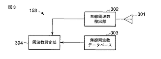
次に、図1の空き周波数検出部153について図3を参照して説明する。
空き周波数検出部153は、空き周波数検出用アンテナ301、無線周波数検出部302、無線周波数データベース303、周波数設定部304を含む。
Next, the idle
The vacant
空き周波数検出用アンテナ301は、複数の周波数のマイクロ波を受信可能なアンテナである。
The idle
無線周波数検出部302は、ある周波数で無線システムによる信号を検出しようとしてこの信号がこの周波数にあるかどうかを判定する。
無線周波数データベース303は、すでに割り当てられている無線周波数のデータであり、どの周波数がどのような無線システムで利用されているかをデータベース化しているものである。
The
周波数設定部304は、他の通信システムが使用していない無線給電に利用可能な1つあるいは複数の周波数を選択し設定する。周波数設定部304は、無線周波数検出部302で検出された周波数と無線周波数データベース303を比較して、無線給電に利用可能な複数の周波数を設定することを特徴とする。
The
このように構成することで、1以上の空き周波数を検出し、無線通信に干渉を起こさない無線給電可能な周波数を検出することが可能になる。 With this configuration, it is possible to detect one or more vacant frequencies and detect a frequency that can be wirelessly fed without causing interference in wireless communication.
以上のように、無線給電システムは構成されているが、無線給電は以下の手順で行われる。
第1に、空き周波数検出部153が1つあるいは複数の空き周波数を検出する。
第2に、検出された空き周波数でマイクロ波送信部152がマイクロ波送信を行い、無線給電部103がこのときの給電量を測定する。
第3に、周波数選択部102が無線給電量の複数の測定値から、マイクロ波送信のための最適周波数を選択する。
第4に、マイクロ波送信部152が最適周波数でマイクロ波送信を行い、無線給電部103が2次電池へ給電を行う。
このような構成とすることにより、無線給電に対して最適な周波数で給電を行え、効率よく無線給電が可能となる。
As described above, the wireless power feeding system is configured, but wireless power feeding is performed in the following procedure.
First, the
Secondly, the
Third, the
Fourth, the
With such a configuration, power can be supplied at an optimal frequency for wireless power supply, and wireless power supply can be performed efficiently.
ここで、本実施形態と従来の電力測定方法との違いを説明する。ここでは、空き周波数を利用して無線通信を行うコグニティブ無線通信システムの場合を例とする。
従来は、通信を行う際にRSSIを調査するために電力測定を行っている例がある。この場合には、アンテナで受信した受信信号をカプラで分岐し、分岐後の一方の受信信号を無線通信部に出力すると共に他方の受信信号を整流回路に出力し、整流回路で直流へと変換し、この直流電流の電力を直流電力測定回路で測定している。測定された直流電力の値と、無線通信回路から得られる送信された周波数の情報から、周波数選択回路が最大の受信電力となる周波数を選択している。
Here, the difference between the present embodiment and the conventional power measurement method will be described. Here, a case of a cognitive radio communication system that performs radio communication using an empty frequency is taken as an example.
Conventionally, there is an example in which power measurement is performed in order to investigate RSSI when performing communication. In this case, the received signal received by the antenna is branched by the coupler, one of the branched received signals is output to the wireless communication unit and the other received signal is output to the rectifier circuit, and converted to DC by the rectifier circuit. The power of the direct current is measured by a direct current power measurement circuit. From the measured DC power value and the transmitted frequency information obtained from the wireless communication circuit, the frequency selection circuit selects the frequency at which the maximum received power is obtained.
このように、従来の無線通信システムにおいても直流電力は測定されているが、従来はカプラで分岐した後の微弱な電力を測定するものである。このため、大電力を取り扱う無線給電部103の整流回路と、従来の微弱な電力を測定する整流回路の間に周波数特性が異なる場合があり、従来の手法では2次電池へ給電可能な正確な電力量を測定できない。
Thus, although the DC power is measured also in the conventional wireless communication system, the weak power after branching by the coupler is conventionally measured. For this reason, the frequency characteristics may be different between the rectifier circuit of the wireless
そこで、本実施形態では、2次時電池へ給電を行うときに用いる整流回路を利用して直流電力を測定している。このために、本実施形態では2次電池へ給電される電力量を正確に測定できるようになっている。 Therefore, in the present embodiment, DC power is measured using a rectifier circuit used when power is supplied to the secondary battery. For this reason, in the present embodiment, the amount of power supplied to the secondary battery can be accurately measured.
(より詳細な例)
本実施形態の無線給電システムの詳細な一例について図4を参照して説明する。
この例では、被給電端末100とマイクロ波送信端末150にそれぞれ第1制御回路401と第2制御回路451を設け、最適な周波数で長時間にわたって無線給電可能となるように構成されている。この例は、第1制御回路401と第2制御回路451が図1の無線給電システムに付加されていて、その他は、図1の無線給電システムと同様である。
(More detailed example)
A detailed example of the wireless power feeding system of the present embodiment will be described with reference to FIG.
In this example, a
マイクロ波送信端末150内の第2制御回路451は、最適周波数を設定する段階においてはマイクロ波送信部152の周波数の設定を行う。また第2制御回路451は、最適周波数で無線給電を行うときには、最適周波数でマイクロ波送信が行えるように設定を行う。
The
被給電端末100内の第1制御回路401は、最適周波数を設定する段階においてはスイッチを切り替え、整流回路202と直流電力測定回路203が接続するように切り替える。また第1制御回路401は、最適周波数で無線給電を行うときには、スイッチを切り替え整流回路202と2次電池104が接続するように切り替える。
The
次に、図4の無線給電システムの動作の一例について図5を参照して説明する。なお、図5の中で左側はマイクロ波送信端末150が行なう手順を示し、右側は被給電端末100が行う手順を示している。これらの動作は、被給電端末100では第1制御回路401によって制御されマイクロ波送信端末150では第2制御回路451によって制御される。
STEP 1:被給電端末100で、第1制御回路401の制御により第1無線通信部101がワイヤレス給電の要求をマイクロ波送信端末150へ行う(ステップS501)。
Next, an example of the operation of the wireless power feeding system in FIG. 4 will be described with reference to FIG. In FIG. 5, the left side shows a procedure performed by the
STEP 1: In the
STEP 2:マイクロ波送信端末150で、第2無線通信部151が被給電端末100からワイヤレス給電の要求を受けたことを第2制御回路451が検出すると、周波数設定部304が周波数候補を選定するように第2制御回路451が周波数設定部304に指示を渡し、周波数設定部304が周波数候補を選定する(ステップS551)。
STEP 3:マイクロ波送信端末150で、第2無線通信部151が、周波数設定部304が選定した複数の候補周波数と第2制御回路451が設定するそれらの送信順番についての情報を被給電端末100へ無線送信する(ステップS552)。
STEP 2: In the
STEP 3: In the
STEP 4:被給電端末100で、第1無線通信部101が複数の候補周波数とそれらの送信順番についての情報をマイクロ波送信端末150から無線受信する(ステップS502)。
STEP 5:被給電端末100で、第1無線通信部101が候補周波数の送信時刻に関する要求を無線送信する(ステップS503)。
STEP 4: In the
STEP 5: In the
STEP 6:マイクロ波送信端末150で、被給電端末100から受信した送信時刻にしたがって、マイクロ波送信部152がマイクロ波送信を被給電端末100へ送信する(ステップS553)。
STEP 6: In the
STEP 7:被給電端末100で、第1制御回路401がスイッチ204を直流電力測定回路203へ切り替え、直流電力測定回路203が候補となる周波数についての直流電力を測定する(ステップS504)。
STEP 8:被給電端末100で、周波数選択部102が、最大直流電力が得られた周波数を最適周波数として選択する(ステップS505)。
STEP 9:被給電端末100で、第1無線通信部101がステップS505で選択された最適周波数についての情報をマイクロ波送信端末150へ無線送信する(ステップS506)。
STEP 7: In the power-supplied
STEP 8: In the power-supplied
STEP 9: In the
STEP10:マイクロ波送信端末150で、第2無線通信部151が被給電端末100から受信した最適周波数の情報にしたがって、第2制御回路451が最適周波数でマイクロ波送信を行う指示をマイクロ波送信部152へ渡し、マイクロ波送信部152が被給電端末100へマイクロ波送信を行う。(ステップS554)。
STEP 10: In the
STEP11:被給電端末100で、第1制御回路401がスイッチ204を2次電池104側へ切り替え、整流回路202によって得られる電流によって2次電池104へ給電を行う(ステップS507)。
STEP12:マイクロ波送信端末150で、第2制御回路451が、マイクロ波送信部152が一定時間後にマイクロ波の送信を停止するようにマイクロ波送信部152に指示し、マイクロ波送信部152がマイクロ波の送信を停止する(ステップS555)。
STEP13:マイクロ波送信端末150で、第2制御回路451が、周波数設定部304が無線周波数検出部302を使用して、別の無線通信システムがステップS505で選択された最適周波数を利用していないかどうかの空き状態を再び調べるように周波数設定部304に指示し、周波数設定部304は再調査する(ステップS556)。
STEP14:マイクロ波送信端末150で、ステップS556の再調査の結果、継続して空いていればSTEP10(ステップS554)のマイクロ波送信を再開する(ステップS557)。ステップS556の再調査の結果、最適周波数が利用できなくなっていれば、STEP2(ステップS551)の空き周波数候補の選定から再びやり直すように第2制御回路451がマイクロ波送信端末150の各部を制御する(ステップS557)。
STEP 11: In the power-supplied
STEP 12: In the
STEP 13: In the
STEP14: If the
STEP15:被給電端末100で、第1制御回路401が2次電池104への充電が完了を検出した場合に、第1制御回路401が、第1無線通信部101が無線給電停止の要求をマイクロ波送信端末150へ無線通信で行うよう制御し、第1無線通信部101がこの無線通信を行う(ステップS508)。
STEP 15: In the power-supplied
STEP16:マイクロ波送信端末150で、第2制御回路451が、第2無線通信部151が無線給電停止の要求を受けたと判定した場合に、マイクロ波送信部152へマイクロ波の送信を停止する指令を渡し、マイクロ波送信部152がマイクロ波の送信を停止する(ステップS558)。
STEP 16: In the
以上の手順にしたがって無線給電を行うことで最適な周波数で長時間にわたって無線給電することが可能になる。その結果、2次電池への給電が十分行えるようになる。また、長時間無線給電をおこなっても、別の無線通信システムへの干渉を最小にすることが可能である。 By performing wireless power supply according to the above procedure, it is possible to perform wireless power supply at an optimum frequency for a long time. As a result, it is possible to sufficiently supply power to the secondary battery. Further, even when wireless power feeding is performed for a long time, interference with another wireless communication system can be minimized.
以上の第1の実施形態によれば、空き周波数の中から、2次電池へ給電可能な電力量を最大化可能な周波数を適切に設定することが可能になる。また、別の無線通信システムへの干渉を最小化しつつ、最大の無線給電を行うことができるようになる。 According to the first embodiment described above, it is possible to appropriately set a frequency capable of maximizing the amount of power that can be supplied to the secondary battery from the free frequencies. In addition, maximum wireless power feeding can be performed while minimizing interference with another wireless communication system.
なお、本実施形態においては、被給電端末内の無線通信用のアンテナと無線給電用のアンテナは別々に構成されているが、一体化して共用されてもよい。この場合には、小型化が行える。また、マイクロは送信端末内の無線通信用アンテナ、マイクロ波送信用アンテナ、空き周波数検出用アンテナは別々に構成されているが、一体化して共用されてもよい。
また、アンテナ以外の構成要素についても、共用化して小型化、低コスト化を行ってもよい。
In this embodiment, the wireless communication antenna and the wireless power supply antenna in the power-supplied terminal are configured separately, but may be integrated and shared. In this case, the size can be reduced. In addition, the micro communication antenna, the microwave transmission antenna, and the vacant frequency detection antenna in the transmission terminal are separately configured in the micro, but may be integrated and shared.
Further, components other than the antenna may be shared to reduce the size and cost.
次に、被給電端末100の整流回路202、および、マイクロ波送信端末150のマイクロ波送信部152で使用するアンテナについて、以下に3つの例を図6、図7、図8を参照して説明する。
(第1の例)
第1の例は整流回路202およびマイクロ波送信部152のアンテナがコイルで形成されている場合である(図6)。コイルで形成されているために、電磁誘導方式の無線給電が可能となる。
マイクロ波を利用した無線給電の方式としては、送受のアンテナをコイルとして、お互いのコイルを対向させ、電磁誘導結合で無線給電する方法が知られている。そこで、第1の例では、電磁誘導で無線給電を行なうために、アンテナをコイルで構成している。
第1の例ではアンテナをコイルで構成して、電磁誘導方式で無線給電を行なうことを可能とする。
Next, three examples of antennas used in the
(First example)
The first example is a case where the antennas of the
As a method of wireless power feeding using microwaves, there is known a method of wireless power feeding by electromagnetic induction coupling using a transmitting / receiving antenna as a coil, with the coils facing each other. Therefore, in the first example, in order to perform wireless power feeding by electromagnetic induction, the antenna is configured by a coil.
In the first example, the antenna is configured by a coil, and wireless power feeding can be performed by an electromagnetic induction method.
(第2の例)
第2の例は整流回路202およびマイクロ波送信部152のアンテナは、同一の共振周波数を有する場合である(図7)。これにより、共鳴型の無線給電を行うことができる。
マイクロ波を利用した無線給電の方式としては、マイクロ波送信側のアンテナの共振周波数とマイクロ波受信側のアンテナの共振周波数を同一として、2つのアンテナを共鳴させ無線給電する共鳴型の方式が知られている。共鳴型においては、アンテナの共振周波数を同一とすることが必要であり、共振周波数を同一とすることで効率よく無線給電が可能となる。
(Second example)
The second example is a case where the
As a wireless power feeding method using microwaves, a resonance type method is known in which the resonance frequency of the antenna on the microwave transmission side is the same as the resonance frequency of the antenna on the microwave reception side and the two antennas are resonated to wirelessly feed power. It has been. In the resonance type, it is necessary to make the antennas have the same resonance frequency, and by making the resonance frequencies the same, wireless power feeding can be performed efficiently.
本実施形態では様々な周波数が用いられるために、第2の例では様々な周波数で共振可能なアンテナを用いる。例えば、複数の周波数で共振させるために、異なる周波数で共振しているアンテナを切り替える。図7は、異なる周波数で共振するアンテナ701、702、703、704を、スイッチ回路705を用いて切り替える場合のアンテナ構成である。図7ではアンテナが4種類の場合を示している。スイッチ回路705は、マイクロ波送信に利用される周波数に応じてスイッチを切り替え、アンテナを選択する。
Since various frequencies are used in this embodiment, an antenna that can resonate at various frequencies is used in the second example. For example, in order to resonate at a plurality of frequencies, the antenna resonating at different frequencies is switched. FIG. 7 shows an antenna configuration when the
(第3の例)
第3の例は、第2の例と実質的に同様であるが、アンテナ801と可変インピーダンス部802を組み合わせて構成されるチューナブルアンテナである場合である(図8)。可変インピーダンス部802は、可変インダクタンス、可変キャパシタンス、可変抵抗を1つずつ、あるいは、複数組み合わせて構成される。可変インピーダンス部802は、可変インピーダンスの値を変えることで、アンテナ801の共振周波数を可変させることが可能となる。
(Third example)
The third example is substantially the same as the second example, but is a case of a tunable antenna configured by combining the
第2の例および第3の例では、本実施形態のマイクロ波受信用アンテナ(整流回路202に接続)とマイクロ波送信部152に用いられるアンテナは、同一の共振周波数を持つことを特徴として、これにより、共鳴型の無線給電が可能となる。
In the second example and the third example, the microwave reception antenna of this embodiment (connected to the rectifier circuit 202) and the antenna used for the
(第2の実施形態)
本実施形態は第1の実施形態での無線給電部103に含まれる装置部分が第1の実施形態とは異なる。本実施形態では、図9に示すように第1実施形態の図2に示す無線給電部103に加えて利得制御回路903が付加され、整流回路901が低利得と高利得の2状態に切り替えることが可能である。
本実施形態の無線給電部103は、整流回路901と直流電力測定回路902、利得制御回路903、スイッチ204を含む。
(Second Embodiment)
The present embodiment is different from the first embodiment in the device portion included in the wireless
The wireless
整流回路901は、低利得と高利得の2状態に切り替えることができ、それぞれの場合にマイクロ波受信用アンテナ201で受信したマイクロ波を直流電流に変換する。低利得、高利得とは、それぞれ直流電流への変換効率が低い場合、高い場合を示している。高利得とした場合には、低利得とした場合に比べて、マイクロ波から直流への変換効率を大きくすることができる。すなわち、無線給電量を大きくすることが可能である。しかし、高利得の場合は低利得に比較して、整流回路901が作動するために、整流回路901に外部から供給される電力の大きさを大きくする必要がある。
The
直流電力測定回路902は、整流回路901で整流された直流電流の電力を測定し、測定した電力値を利得制御回路903に渡す。直流電力測定回路902は測定された直流電力量を用いて無線給電量を測定する。
The DC
利得制御回路903は、整流回路901を低利得としたときの直流電力測定回路902の測定値に応じて、直流電流を2次電池104へ給電するときの整流回路901の利得を切り替える。その他の構成は、第1の実施形態と同一であるので、説明を省略する。利得制御回路903は、低利得とした状態で直流電力測定回路902が測定した電流値が閾値よりも大きい場合には高利得の状態へ切り替え、低利得とした状態で直流電力測定回路902が測定した電流値が閾値以下である場合には低利得の状態を維持する。
The
本実施形態では、整流回路901は、高利得と低利得の2つの状態に切り替えることが可能である。高利得とした場合には、低利得とした場合に比べて、マイクロ波から直流への変換効率を大きくすることができる。すなわち、無線給電量を大きくすることが可能である。
In this embodiment, the
ところが、高利得とする場合には、整流回路901へ電力を供給しなくてはならない。高利得としたときに無線給電で給電できる電力P1と整流回路901で消費される電力P2の差(P1−P2)がマイナスとなると、無線給電を行なっても、被給電端末100内の電力量は減ってしまう。つまり、高利得としたときの実質的な給電量は(P1−P2)となる。
However, in order to obtain a high gain, power must be supplied to the
P2の値は、整流回路901の構成によってあらかじめ測定することが可能である。また、P1の値は、整流回路901を低利得としたときに給電できる電力P3の値から求めることが可能である。P3の値とマイクロ波受信用アンテナ201で受信したマイクロ波の強度は1対1の関係であり、このマイクロ波の強度とP3の値も1対1の関係であるので、あらかじめ求めることが可能である。
The value of P2 can be measured in advance by the configuration of the
本実施形態においては、(P1−P2)>P3を利得切り替えの基準とする。利得制御回路903は、(P1−P2)≦P3の場合には、高利得としても実質的な給電量が減少してしまうので、低利得状態とする。つまり、利得制御回路903は(P1−P2−P3)を閾値として利得の切り替えを行う。利得制御回路903は、(P1−P2−P3)>0の場合には整流回路901を高利得へと切り替え、(P1−P2−P3)≦0の場合には、整流回路901を低利得へと切り替える。
In the present embodiment, (P1-P2)> P3 is used as a reference for gain switching. When (P1−P2) ≦ P3, the
第2の実施形態によれば、整流回路を低利得状態としたときの直流電力測定回路の測定値が閾値よりも大きいかどうかによって、無線給電に用いる整流回路901の利得を切り替える。これにより、マイクロ波受信アンテナで受信したマイクロ波の強度が大きいときには高利得とし無線給電量を改善し、マイクロ波の強度が小さいときには低利得として無駄な消費電力を抑えながら無線給電を可能とすることができる。
According to the second embodiment, the gain of the
(第3の実施形態)
本実施形態は、図10に示すように第1の実施形態での被給電端末100およびマイクロ波送信端末150にそれぞれ位置情報取得部を含むことが、第1の実施形態とは異なる。
被給電端末100は第1位置情報取得部1001を含み、マイクロ波送信端末150は第2位置情報取得部1051を含む。本実施形態の無線給電システムは、第1位置情報取得部1001と第2位置情報取得部1051との情報をやり取りして、被給電端末100とマイクロ波送信端末150との距離が閾値よりも小さい場合だけ、無線給電を行うことを特徴とする。
(Third embodiment)
This embodiment is different from the first embodiment in that each of the power-supplied
Power-supplied
より詳細には、被給電端末100で、マイクロ波送信端末150が取得した第2位置情報を第1無線通信部101が取得し、第2位置情報と第1位置情報取得部1001が取得した第1位置情報とにより被給電端末100とマイクロ波送信端末150との距離を第1制御回路401が比較しこの距離が閾値よりも小さいかどうかを判定する。この動作は、マイクロ波送信端末150でも行ってもよい。
More specifically, in the
被給電端末100とマイクロ波送信端末150との間の距離が閾値よりも近いときだけ無線給電を行なうことにより、端末間の距離が大きく、無線給電量が非常に小さくなると予想されるときには、無線給電を行なわない。無線給電量が非常に小さい場合、マイクロ波の送信電力のほとんどは損失となり無駄となる。そこで本実施形態によれば、このような無駄な電力損失を小さくすることが可能である。
By performing wireless power supply only when the distance between the power-supplied
第1位置情報取得部1001と第2位置情報取得部1051はGPSを用いればよい。また、端末(通常はマイクロ波送信端末150)が固定されている場合には、対応する位置情報取得部にあらかじめ位置情報を入力すればよい。
The first position
第3の実施形態によれば、被給電端末とマイクロ波送信端末に、それぞれ、位置情報取得手段を追加することで、両者の距離が明らかになり、無線給電を行うか、無線給電を行なわないかを切り替えることが可能となる。無線給電量が非常に小さい場合の無駄な電力消費を削減することが可能となる。 According to the third embodiment, by adding position information acquisition means to each of the power-supplied terminal and the microwave transmission terminal, the distance between the two becomes clear, and wireless power feeding is performed or wireless power feeding is not performed. Can be switched. It is possible to reduce wasteful power consumption when the wireless power supply amount is very small.
以上に示した実施形態によれば、空き周波数の中から、2次電池へ給電可能な電力量を最大化可能な周波数を適切に設定して、別の無線通信システムへの干渉を最小化しつつ、この周波数を利用して最大の無線給電を行うことができるようになる。
なお、本実施形態においては、被給電端末内の無線通信用のアンテナと無線給電用のアンテナは別々に構成されているが、一体化して共用されてもよい。この場合には、小型化が行える。また、マイクロは送信端末内の無線通信用アンテナ、マイクロ波送信用アンテナ、空き周波数検出用アンテナは別々に構成されているが、一体化して共用されてもよい。
また、アンテナ以外の構成要素についても、共用化して小型化、低コスト化を行ってもよい。
According to the above-described embodiment, the frequency that can maximize the amount of power that can be supplied to the secondary battery is appropriately set from among the available frequencies, while minimizing interference with another wireless communication system. The maximum wireless power supply can be performed using this frequency.
In this embodiment, the wireless communication antenna and the wireless power supply antenna in the power-supplied terminal are configured separately, but may be integrated and shared. In this case, the size can be reduced. In addition, the micro communication antenna, the microwave transmission antenna, and the vacant frequency detection antenna in the transmission terminal are separately configured in the micro, but may be integrated and shared.
Further, components other than the antenna may be shared to reduce the size and cost.
その他、複数の周波数対応のための構成、無線給電量の向上、低消費電力化、低コスト化、無線通信と無線給電の共存を実現することができる。 In addition, a configuration for supporting a plurality of frequencies, improvement in the amount of wireless power supply, reduction in power consumption, cost reduction, and coexistence of wireless communication and wireless power supply can be realized.
なお、本発明は上記実施形態そのままに限定されるものではなく、実施段階ではその要旨を逸脱しない範囲で構成要素を変形して具体化できる。また、上記実施形態に開示されている複数の構成要素の適宜な組み合わせにより、種々の発明を形成できる。例えば、実施形態に示される全構成要素から幾つかの構成要素を削除してもよい。さらに、異なる実施形態にわたる構成要素を適宜組み合わせてもよい。 Note that the present invention is not limited to the above-described embodiment as it is, and can be embodied by modifying the constituent elements without departing from the scope of the invention in the implementation stage. In addition, various inventions can be formed by appropriately combining a plurality of components disclosed in the embodiment. For example, some components may be deleted from all the components shown in the embodiment. Furthermore, constituent elements over different embodiments may be appropriately combined.
100・・・被給電端末、101・・・第1無線通信部、102・・・周波数選択部、103・・・無線給電部、104・・・2次電池、150・・・マイクロ波送信端末、151・・・第2無線通信部、152・・・マイクロ波送信部、153・・・空き周波数検出部、201・・・マイクロ波受信用アンテナ、202、901・・・整流回路、203、902・・・直流電力測定回路、204・・・スイッチ、301・・・周波数検出用アンテナ、302・・・無線周波数検出部、303・・・無線周波数データベース、304・・・周波数設定部、401・・・第1制御回路、451・・・第2制御回路、701〜801・・・アンテナ、705・・・スイッチ回路、802・・・可変インピーダンス部、903・・・利得制御回路、1001・・・第1位置情報取得部、1051・・・第2位置情報取得部。
DESCRIPTION OF
Claims (14)
前記第1情報に含まれる周波数候補で前記他端末から送信されたマイクロ波を受信する第2受信手段と、
前記マイクロ波のエネルギーを直流エネルギーに変換する変換手段と、
前記直流エネルギーのうちの、最大のエネルギーとなる最適周波数を含む第2情報を前記他端末に送信する送信手段と、
前記最適周波数での、前記第2受信手段が受信するマイクロ波を前記変換手段が変換した直流エネルギーを受け取る2次電池と、を具備することを特徴とする被給電端末。 First receiving means for receiving, from another terminal, first information including one or more frequency candidates for transmitting microwaves, which are not used by another communication system;
Second receiving means for receiving a microwave transmitted from the other terminal at a frequency candidate included in the first information;
Conversion means for converting the microwave energy into DC energy;
Transmitting means for transmitting the second information including the optimum frequency that is the maximum energy of the DC energy to the other terminal;
A power-supplied terminal, comprising: a secondary battery that receives DC energy obtained by converting the microwave received by the second receiving unit at the optimum frequency by the converting unit.
前記変換手段は、
前記マイクロ受信用アンテナで受信したマイクロ波を直流電流に変換する整流回路と、
前記周波数候補ごとに前記直流電流の電流値を測定する測定手段と、
前記電流値のうちの、最大の電流値となる最適周波数を選択する選択手段と、
前記直流電流の接続先を前記測定手段と前記2次電池との間で切り替えるスイッチと、を含むことを特徴とする請求項1に記載の被給電端末。 The second receiving means includes a microwave receiving antenna;
The converting means includes
A rectifying circuit that converts a microwave received by the antenna for micro reception into a direct current;
Measuring means for measuring the current value of the direct current for each frequency candidate;
A selection means for selecting an optimum frequency that is a maximum current value among the current values;
The power-supplied terminal according to claim 1, further comprising: a switch that switches a connection destination of the direct current between the measurement unit and the secondary battery.
前記第1受信手段が他端末の第2位置情報を受信し、
前記被給電端末は、前記第1位置情報と前記第2位置情報から自端末と他端末との距離を求め、該距離が閾値よりも小さい場合のみ前記変換手段および前記送信手段を動作させる制御部をさらに具備することを特徴とする請求項1から請求項3のいずれか1項に記載の被給電端末。 Further comprising an acquisition means for acquiring the first location information of the terminal itself;
The first receiving means receives second position information of another terminal;
The power-supplied terminal obtains a distance between the terminal itself and another terminal from the first position information and the second position information, and operates the conversion unit and the transmission unit only when the distance is smaller than a threshold value. The power-supplied terminal according to any one of claims 1 to 3, further comprising:
前記第1情報に含まれる周波数候補で前記他端末から送信されたマイクロ波を受信する第2受信手段と、
前記マイクロ波を直流電流に変換する変換手段と、
前記周波数候補ごとに前記直流電流の電流値を測定する測定手段と、
前記電流値のうちの、最大の電流値となる最適周波数を選択する選択手段と、
前記最適周波数を含む第2情報を前記他端末に送信する送信手段と、
前記測定手段が測定した前記最適周波数での、前記第2受信手段が受信するマイクロ波を前記変換手段が変換した直流電流を受け取る2次電池と、を具備することを特徴とする被給電端末。 First receiving means for receiving, from another terminal, first information including one or more frequency candidates for transmitting microwaves that are not used by another wireless system;
Second receiving means for receiving a microwave transmitted from the other terminal at a frequency candidate included in the first information;
Conversion means for converting the microwave into a direct current;
Measuring means for measuring the current value of the direct current for each frequency candidate;
A selection means for selecting an optimum frequency that is a maximum current value among the current values;
Transmitting means for transmitting second information including the optimum frequency to the other terminal;
A power-supplied terminal comprising: a secondary battery that receives a direct current obtained by converting the microwave received by the second receiving means at the optimum frequency measured by the measuring means.
前記第2端末は、
他の無線システムが使用していない、前記マイクロ波を送信する周波数候補を1以上選択する第1選択手段と、
前記周波数候補を含む第1情報を前記第1端末に送信する第1送信手段と、
前記周波数候補で前記マイクロ波を前記第1端末に送信する第2送信手段と、を具備し、
前記第1端末は、
前記第1情報を受信する第1受信手段と、
前記第1情報に含まれる周波数候補で前記マイクロ波を受信する第2受信手段と、
前記マイクロ波を直流電流に変換する変換手段と、
前記周波数候補ごとに前記直流電流の電流値を測定する測定手段と、
前記電流値のうちの、最大の電流値となる最適周波数を選択する第2選択手段と、
前記最適周波数を含む第2情報を前記第2端末に送信する第3送信手段と、を具備し、
前記第2端末は、
前記第2情報を受信する第3受信手段と、
前記第2情報に含まれる最適周波数でマイクロ波を前記第1端末に送信する第4送信手段と、をさらに具備し、
前記第1端末は、
前記測定手段が測定した前記最適周波数での、前記第2受信手段が受信するマイクロ波を前記変換手段が変換した直流電流を受け取る2次電池をさらに具備することを特徴とする無線給電システム。 A wireless power supply system including a first terminal that requests power supply to another terminal and a second terminal that receives a request from the first terminal and transmits a microwave to the first terminal,
The second terminal is
First selection means for selecting one or more frequency candidates for transmitting the microwave that are not used by other wireless systems;
First transmission means for transmitting first information including the frequency candidates to the first terminal;
Second transmission means for transmitting the microwave to the first terminal with the frequency candidate,
The first terminal is
First receiving means for receiving the first information;
Second receiving means for receiving the microwave at a frequency candidate included in the first information;
Conversion means for converting the microwave into a direct current;
Measuring means for measuring the current value of the direct current for each frequency candidate;
A second selection means for selecting an optimum frequency that is a maximum current value among the current values;
Third transmission means for transmitting second information including the optimum frequency to the second terminal, and
The second terminal is
Third receiving means for receiving the second information;
A fourth transmission means for transmitting a microwave to the first terminal at an optimum frequency included in the second information,
The first terminal is
The wireless power feeding system further comprising: a secondary battery that receives a direct current obtained by converting the microwave received by the second receiving unit at the optimum frequency measured by the measuring unit.
複数の周波数のマイクロ波を受信可能なアンテナと、
前記アンテナから信号を受け取り、ある周波数で無線システムによる信号があるかどうかを判定する判定手段と、
既に利用されている無線システムと該無線システムが使用する周波数との情報を格納している格納手段と、
他の無線システムが使用していない、前記格納手段に含まれる周波数のうち、前記判定手段が無線システムによる信号がないと判定した周波数候補を1以上選択し設定する設定手段と、を含むことを特徴とする請求項8に記載の無線給電システム。 The first selection means includes
An antenna capable of receiving microwaves of multiple frequencies;
Determining means for receiving a signal from the antenna and determining whether there is a signal from a wireless system at a certain frequency;
Storage means for storing information on a wireless system already used and a frequency used by the wireless system;
And setting means for selecting and setting one or more frequency candidates determined by the determination means that there is no signal from the wireless system among frequencies included in the storage means that are not used by other wireless systems. The wireless power feeding system according to claim 8, wherein:
前記第2端末は、自端末の第2位置情報を取得する第2取得手段をさらに具備し、
前記第1受信手段が前記第2位置情報を受信し、
前記第1端末は、前記第1位置情報と前記第2位置情報から第1端末と第2端末との距離を求め、該距離が閾値よりも小さい場合のみ前記変換手段、前記測定手段、前記第2選択手段および前記第3送信手段を動作させる制御部をさらに具備することを特徴とする請求項8または請求項9に記載の無線給電システム。 The first terminal further comprises first acquisition means for acquiring first position information of the terminal itself;
The second terminal further comprises second acquisition means for acquiring second position information of the terminal,
The first receiving means receives the second position information;
The first terminal obtains a distance between the first terminal and the second terminal from the first position information and the second position information, and only when the distance is smaller than a threshold value, the converting means, the measuring means, 10. The wireless power feeding system according to claim 8, further comprising a control unit that operates two selection means and the third transmission means. 11.
前記第1情報に含まれる周波数候補で前記他端末から送信されたマイクロ波を受信し、
前記マイクロ波のエネルギーを直流エネルギーに変換し、
前記直流エネルギーのうちの、最大のエネルギーとなる最適周波数を含む第2情報を前記他端末に送信し、
前記最適周波数で受信したマイクロ波を変換した直流エネルギーを受け取る2次電池を用意することを特徴とする無線給電方法。 Receiving, from another terminal, first information including one or more frequency candidates for transmitting microwaves that are not used by another communication system;
Receiving a microwave transmitted from the other terminal at a frequency candidate included in the first information;
Converting the microwave energy into direct current energy;
Sending the second information including the optimum frequency that is the maximum energy of the DC energy to the other terminal,
A wireless power feeding method comprising: preparing a secondary battery that receives DC energy obtained by converting microwaves received at the optimum frequency.
前記第2端末で、
他の無線システムが使用していない、前記マイクロ波を送信する周波数候補を1以上選択し、
前記周波数候補を含む第1情報を前記第1端末に送信し、
前記周波数候補で前記マイクロ波を前記第1端末に送信し、
前記第1端末で、
前記第1情報を受信し、
前記第1情報に含まれる周波数候補で前記マイクロ波を受信し、
前記マイクロ波を直流電流に変換し、
前記周波数候補ごとに前記直流電流の電流値を測定し、
前記電流値のうちの、最大の電流値となる最適周波数を選択し、
前記最適周波数を含む第2情報を前記第2端末に送信し、
前記第2端末で、
前記第2情報を受信し、
前記第2情報に含まれる最適周波数でマイクロ波を前記第1端末に送信し、
前記第1端末は、
前記最適周波数での、前記第1端末が受信するマイクロ波を変換した直流電流を受け取る2次電池を用意することを特徴とする無線給電方法。 A power supply method used in a wireless power supply system including a first terminal that requests power supply to another terminal and a second terminal that receives a request from the first terminal and transmits a microwave to the first terminal,
In the second terminal,
Select one or more frequency candidates for transmitting the microwave that are not used by other wireless systems,
Transmitting first information including the frequency candidates to the first terminal;
Transmitting the microwave to the first terminal with the frequency candidate;
In the first terminal,
Receiving the first information;
Receiving the microwave at a frequency candidate included in the first information;
Converting the microwave to a direct current;
Measure the current value of the direct current for each frequency candidate,
Among the current values, select the optimum frequency that becomes the maximum current value,
Transmitting second information including the optimum frequency to the second terminal;
In the second terminal,
Receiving the second information;
Transmitting a microwave to the first terminal at an optimum frequency included in the second information;
The first terminal is
A wireless power feeding method, comprising: preparing a secondary battery that receives a direct current obtained by converting a microwave received by the first terminal at the optimum frequency.
Priority Applications (2)
| Application Number | Priority Date | Filing Date | Title |
|---|---|---|---|
| JP2008083432A JP4987775B2 (en) | 2008-03-27 | 2008-03-27 | Wireless powered terminal, system and method |
| US12/369,857 US8095159B2 (en) | 2008-03-27 | 2009-02-12 | Radio power-fed terminal, system, and method |
Applications Claiming Priority (1)
| Application Number | Priority Date | Filing Date | Title |
|---|---|---|---|
| JP2008083432A JP4987775B2 (en) | 2008-03-27 | 2008-03-27 | Wireless powered terminal, system and method |
Publications (2)
| Publication Number | Publication Date |
|---|---|
| JP2009239640A JP2009239640A (en) | 2009-10-15 |
| JP4987775B2 true JP4987775B2 (en) | 2012-07-25 |
Family
ID=41118017
Family Applications (1)
| Application Number | Title | Priority Date | Filing Date |
|---|---|---|---|
| JP2008083432A Active JP4987775B2 (en) | 2008-03-27 | 2008-03-27 | Wireless powered terminal, system and method |
Country Status (2)
| Country | Link |
|---|---|
| US (1) | US8095159B2 (en) |
| JP (1) | JP4987775B2 (en) |
Families Citing this family (23)
| Publication number | Priority date | Publication date | Assignee | Title |
|---|---|---|---|---|
| US9602167B2 (en) * | 2012-03-28 | 2017-03-21 | Triune Systems, LLC | Remote energy transfer system |
| US10854378B2 (en) | 2009-02-23 | 2020-12-01 | Triune Ip Llc | Wireless power transmittal |
| US8353903B2 (en) * | 2009-05-06 | 2013-01-15 | Vivant Medical, Inc. | Power-stage antenna integrated system |
| US8798236B2 (en) | 2010-01-29 | 2014-08-05 | Fujifilm Corporation | Radiographic image capturing apparatus and radiographic image capturing system |
| JP5758617B2 (en) * | 2010-02-23 | 2015-08-05 | 富士フイルム株式会社 | Radiation imaging apparatus and power supply method for radiation imaging apparatus |
| JP2011172437A (en) * | 2010-02-22 | 2011-09-01 | Nec Casio Mobile Communications Ltd | Communication apparatus, and program |
| JP5628098B2 (en) * | 2010-06-30 | 2014-11-19 | 富士フイルム株式会社 | Radiation imaging system and power supply method for radiation imaging apparatus |
| US8929510B2 (en) | 2010-06-30 | 2015-01-06 | Fujifilm Corporation | Radiographic image capturing apparatus and radiographic image capturing system |
| KR101735558B1 (en) * | 2010-11-10 | 2017-05-16 | 삼성전자주식회사 | Resonance Power Transmission System and Method to Control Resonance Power Transmitting and Receiving |
| KR101831871B1 (en) * | 2010-12-22 | 2018-02-27 | 인텔렉추얼디스커버리 주식회사 | Wireless energy collection apparatus and wireless electronic label adopting the same |
| JP2013102643A (en) * | 2011-11-09 | 2013-05-23 | Tokai Rika Co Ltd | Non-contact charger |
| US9246357B2 (en) * | 2011-12-07 | 2016-01-26 | Semiconductor Energy Laboratory Co., Ltd. | Contactless power feeding system |
| KR102008808B1 (en) * | 2012-12-13 | 2019-10-21 | 엘지이노텍 주식회사 | Wireless power receiver and controlling method thereof |
| JP6761316B2 (en) | 2016-09-20 | 2020-09-23 | 株式会社東芝 | Wireless communication device and wireless communication method |
| WO2018184230A1 (en) * | 2017-04-07 | 2018-10-11 | Oppo广东移动通信有限公司 | Wireless charging system, apparatus and method, and device to be charged |
| KR101847814B1 (en) * | 2017-05-08 | 2018-04-11 | 삼성전자주식회사 | Resonance Power Transmission System and Method to Control Resonance Power Transmitting and Receiving |
| JP6899357B2 (en) * | 2018-06-20 | 2021-07-07 | 株式会社東芝 | Electronics, systems and power supply methods |
| JP7254889B2 (en) * | 2018-08-07 | 2023-04-10 | 株式会社東芝 | Wireless power transmission device and wireless power transmission method |
| JP2020025400A (en) | 2018-08-07 | 2020-02-13 | 株式会社東芝 | Wireless transmission device and wireless transmission method |
| JP6852028B2 (en) * | 2018-09-04 | 2021-03-31 | 株式会社東芝 | Electronic devices and methods |
| JP7021059B2 (en) * | 2018-12-05 | 2022-02-16 | 株式会社東芝 | Electronic devices and methods |
| JP6937287B2 (en) * | 2018-12-06 | 2021-09-22 | 株式会社東芝 | Electronics and methods |
| JP7471028B1 (en) | 2023-07-26 | 2024-04-19 | エイターリンク株式会社 | Wireless power supply system |
Family Cites Families (11)
| Publication number | Priority date | Publication date | Assignee | Title |
|---|---|---|---|---|
| JP2003070187A (en) * | 2001-08-27 | 2003-03-07 | Toshiba Eng Co Ltd | Non-contacting data carrier device and method for charging built-in secondary battery |
| JP2004096262A (en) * | 2002-08-30 | 2004-03-25 | Matsushita Electric Ind Co Ltd | Portable radiotelephone and noncontact charger |
| JP2004127276A (en) | 2002-09-09 | 2004-04-22 | Ntn Corp | Wireless sensor system and bearing device with wireless sensor |
| JP2004194301A (en) * | 2002-11-29 | 2004-07-08 | Toyota Central Res & Dev Lab Inc | Activation signal output circuit and decision circuit |
| JP2005237155A (en) * | 2004-02-20 | 2005-09-02 | Macnica Inc | Battery charger applicable to multiple-voltage specifications, battery charging system, and battery unit |
| US20070042729A1 (en) * | 2005-08-16 | 2007-02-22 | Baaman David W | Inductive power supply, remote device powered by inductive power supply and method for operating same |
| JP2007088940A (en) | 2005-09-22 | 2007-04-05 | Toshiba Corp | Cognitive communication system and cognitive communication method |
| JP4626855B2 (en) * | 2006-03-01 | 2011-02-09 | 日本電気株式会社 | Mobile information communication terminal, access method to wireless tag, and control program |
| JP5469799B2 (en) * | 2006-03-15 | 2014-04-16 | 株式会社半導体エネルギー研究所 | Semiconductor device that communicates data by wireless communication |
| JP2008009910A (en) * | 2006-06-30 | 2008-01-17 | Citizen Holdings Co Ltd | Ic card and ic card reading system |
| US8446248B2 (en) * | 2007-06-14 | 2013-05-21 | Omnilectric, Inc. | Wireless power transmission system |
-
2008
- 2008-03-27 JP JP2008083432A patent/JP4987775B2/en active Active
-
2009
- 2009-02-12 US US12/369,857 patent/US8095159B2/en active Active
Also Published As
| Publication number | Publication date |
|---|---|
| JP2009239640A (en) | 2009-10-15 |
| US20090247199A1 (en) | 2009-10-01 |
| US8095159B2 (en) | 2012-01-10 |
Similar Documents
| Publication | Publication Date | Title |
|---|---|---|
| JP4987775B2 (en) | Wireless powered terminal, system and method | |
| US10355529B2 (en) | Wireless power receiver and control method thereof | |
| US10211678B2 (en) | Wireless charging apparatus and wireless charging method | |
| KR101968519B1 (en) | Wireless power transmitter and method for controlling thereof | |
| KR101959758B1 (en) | Wireless power transmitter and method for controlling thereof | |
| JP5556044B2 (en) | Wireless power transmission system, wireless power receiving device, and wireless power transmitting device | |
| KR101962667B1 (en) | Wireless power transmitter, wireless power receiver and method for controlling each thereof | |
| KR101950688B1 (en) | Wireless power transmitter and method for controlling thereof | |
| EP3282590B1 (en) | Wireless power transmitter for excluding cross-connected wireless power receiver and method for controlling the same | |
| JP6702688B2 (en) | Wireless power transmission system and power receiving device | |
| US9680335B2 (en) | Apparatus for transmitting and receiving wireless power | |
| KR101059657B1 (en) | Wireless power transceiver and method | |
| US20140247004A1 (en) | Method, apparatus, and computer program product for foreign object detection parameter and charging data communication with wireless charging capable battery pack | |
| US20130181665A1 (en) | Wireless power transmitter, wireless power receiver, and control methods thereof | |
| KR101515479B1 (en) | Multi-mode wireless power receiver and wireless power receiving method thereof | |
| KR20120135885A (en) | Wireless power transmitting/receiving system comprising transmitter and receiver, two-way communication method between the transmitter and the receiver, and the apparatuses | |
| KR20170065236A (en) | Wireless Charging apparatus, and Method for wirelessly transmitting power, and recording media therefor | |
| KR101171937B1 (en) | Multi-node wireless power transmission system and wirelss chargeable device using magnetic resonance induction | |
| KR20140087526A (en) | wireless power transmitter and method for controlling thereof | |
| US20140159673A1 (en) | Wireless charging apparatus and method | |
| JP2015119559A (en) | Electronic apparatus, method, and program | |
| JP2015008619A (en) | Wireless power transmission and reception device | |
| KR20160025261A (en) | The Wireless Power Transmitting Communication System and thereof Method for Wireless Power Transmission | |
| KR102115459B1 (en) | Apparatus and method for wireless charge | |
| KR20160034815A (en) | Electronic apparatus and power supply apparatus |
Legal Events
| Date | Code | Title | Description |
|---|---|---|---|
| A621 | Written request for application examination |
Free format text: JAPANESE INTERMEDIATE CODE: A621 Effective date: 20101015 |
|
| A977 | Report on retrieval |
Free format text: JAPANESE INTERMEDIATE CODE: A971007 Effective date: 20120319 |
|
| TRDD | Decision of grant or rejection written | ||
| A01 | Written decision to grant a patent or to grant a registration (utility model) |
Free format text: JAPANESE INTERMEDIATE CODE: A01 Effective date: 20120403 |
|
| A01 | Written decision to grant a patent or to grant a registration (utility model) |
Free format text: JAPANESE INTERMEDIATE CODE: A01 |
|
| A61 | First payment of annual fees (during grant procedure) |
Free format text: JAPANESE INTERMEDIATE CODE: A61 Effective date: 20120425 |
|
| R151 | Written notification of patent or utility model registration |
Ref document number: 4987775 Country of ref document: JP Free format text: JAPANESE INTERMEDIATE CODE: R151 |
|
| FPAY | Renewal fee payment (event date is renewal date of database) |
Free format text: PAYMENT UNTIL: 20150511 Year of fee payment: 3 |