JP4982976B2 - Flexible substrate manufacturing method and display element - Google Patents
Flexible substrate manufacturing method and display element Download PDFInfo
- Publication number
- JP4982976B2 JP4982976B2 JP2005189453A JP2005189453A JP4982976B2 JP 4982976 B2 JP4982976 B2 JP 4982976B2 JP 2005189453 A JP2005189453 A JP 2005189453A JP 2005189453 A JP2005189453 A JP 2005189453A JP 4982976 B2 JP4982976 B2 JP 4982976B2
- Authority
- JP
- Japan
- Prior art keywords
- resin
- substrate
- base material
- flexible substrate
- resin base
- Prior art date
- Legal status (The legal status is an assumption and is not a legal conclusion. Google has not performed a legal analysis and makes no representation as to the accuracy of the status listed.)
- Expired - Fee Related
Links
- 239000000758 substrate Substances 0.000 title claims description 130
- 238000004519 manufacturing process Methods 0.000 title claims description 30
- 239000011347 resin Substances 0.000 claims description 125
- 229920005989 resin Polymers 0.000 claims description 125
- 239000011521 glass Substances 0.000 claims description 62
- 239000000463 material Substances 0.000 claims description 50
- 239000002904 solvent Substances 0.000 claims description 21
- 238000007789 sealing Methods 0.000 claims description 19
- -1 polyethylene terephthalate Polymers 0.000 claims description 17
- 229920003050 poly-cycloolefin Polymers 0.000 claims description 16
- 239000003960 organic solvent Substances 0.000 claims description 15
- 229920000139 polyethylene terephthalate Polymers 0.000 claims description 6
- 239000005020 polyethylene terephthalate Substances 0.000 claims description 6
- 239000004973 liquid crystal related substance Substances 0.000 claims description 5
- 229920003207 poly(ethylene-2,6-naphthalate) Polymers 0.000 claims description 5
- 229920000515 polycarbonate Polymers 0.000 claims description 5
- 239000004417 polycarbonate Substances 0.000 claims description 5
- 239000011112 polyethylene naphthalate Substances 0.000 claims description 5
- 229920000058 polyacrylate Polymers 0.000 claims description 4
- 229920001230 polyarylate Polymers 0.000 claims description 4
- 238000005401 electroluminescence Methods 0.000 claims description 3
- 239000004695 Polyether sulfone Substances 0.000 claims description 2
- 229920006393 polyether sulfone Polymers 0.000 claims description 2
- 239000002585 base Substances 0.000 description 40
- 238000000034 method Methods 0.000 description 22
- 230000004888 barrier function Effects 0.000 description 14
- XLYOFNOQVPJJNP-UHFFFAOYSA-N water Chemical compound O XLYOFNOQVPJJNP-UHFFFAOYSA-N 0.000 description 14
- 238000003466 welding Methods 0.000 description 14
- 238000011282 treatment Methods 0.000 description 12
- 125000000022 2-aminoethyl group Chemical group [H]C([*])([H])C([H])([H])N([H])[H] 0.000 description 11
- 239000002987 primer (paints) Substances 0.000 description 11
- 238000000576 coating method Methods 0.000 description 10
- 239000000853 adhesive Substances 0.000 description 9
- 230000001070 adhesive effect Effects 0.000 description 9
- 239000011248 coating agent Substances 0.000 description 9
- 239000006087 Silane Coupling Agent Substances 0.000 description 8
- 238000004381 surface treatment Methods 0.000 description 8
- 230000000052 comparative effect Effects 0.000 description 6
- 239000000126 substance Substances 0.000 description 6
- QVGXLLKOCUKJST-UHFFFAOYSA-N atomic oxygen Chemical compound [O] QVGXLLKOCUKJST-UHFFFAOYSA-N 0.000 description 5
- 239000001301 oxygen Substances 0.000 description 5
- 229910052760 oxygen Inorganic materials 0.000 description 5
- 238000005452 bending Methods 0.000 description 4
- 238000004090 dissolution Methods 0.000 description 4
- BAPJBEWLBFYGME-UHFFFAOYSA-N Methyl acrylate Chemical compound COC(=O)C=C BAPJBEWLBFYGME-UHFFFAOYSA-N 0.000 description 3
- YXFVVABEGXRONW-UHFFFAOYSA-N Toluene Chemical compound CC1=CC=CC=C1 YXFVVABEGXRONW-UHFFFAOYSA-N 0.000 description 3
- 239000003522 acrylic cement Substances 0.000 description 3
- 125000003277 amino group Chemical group 0.000 description 3
- 239000012298 atmosphere Substances 0.000 description 3
- 230000007547 defect Effects 0.000 description 3
- 238000001035 drying Methods 0.000 description 3
- 125000003700 epoxy group Chemical group 0.000 description 3
- 230000006698 induction Effects 0.000 description 3
- 238000005259 measurement Methods 0.000 description 3
- 229920000642 polymer Polymers 0.000 description 3
- 238000012360 testing method Methods 0.000 description 3
- WYTZZXDRDKSJID-UHFFFAOYSA-N (3-aminopropyl)triethoxysilane Chemical compound CCO[Si](OCC)(OCC)CCCN WYTZZXDRDKSJID-UHFFFAOYSA-N 0.000 description 2
- ZUCADJKKDINPSW-UHFFFAOYSA-N 3-[dibutoxy(ethyl)silyl]propan-1-amine Chemical compound CCCCO[Si](CC)(CCCN)OCCCC ZUCADJKKDINPSW-UHFFFAOYSA-N 0.000 description 2
- LAYIREOMKATBAT-UHFFFAOYSA-N 3-[dibutoxy(methyl)silyl]propan-1-amine Chemical compound CCCCO[Si](C)(CCCN)OCCCC LAYIREOMKATBAT-UHFFFAOYSA-N 0.000 description 2
- BNYFUBOZYDQIDU-UHFFFAOYSA-N 3-[diethoxy(ethyl)silyl]propan-1-amine Chemical compound CCO[Si](CC)(OCC)CCCN BNYFUBOZYDQIDU-UHFFFAOYSA-N 0.000 description 2
- ZYAASQNKCWTPKI-UHFFFAOYSA-N 3-[dimethoxy(methyl)silyl]propan-1-amine Chemical compound CO[Si](C)(OC)CCCN ZYAASQNKCWTPKI-UHFFFAOYSA-N 0.000 description 2
- TZVMHTHUWCFVQH-UHFFFAOYSA-N 3-[ethyl(dimethoxy)silyl]propan-1-amine Chemical compound CC[Si](OC)(OC)CCCN TZVMHTHUWCFVQH-UHFFFAOYSA-N 0.000 description 2
- BIVVIEVQKUOEEC-UHFFFAOYSA-N 3-[ethyl-di(propan-2-yloxy)silyl]propan-1-amine Chemical compound CC(C)O[Si](OC(C)C)(CC)CCCN BIVVIEVQKUOEEC-UHFFFAOYSA-N 0.000 description 2
- LHNRUQHMRIZFHY-UHFFFAOYSA-N 3-[methyl-di(propan-2-yloxy)silyl]propan-1-amine Chemical compound CC(C)O[Si](C)(OC(C)C)CCCN LHNRUQHMRIZFHY-UHFFFAOYSA-N 0.000 description 2
- OXKAXHPVFLEQHV-UHFFFAOYSA-N 3-tri(propan-2-yloxy)silylpropan-1-amine Chemical compound CC(C)O[Si](OC(C)C)(OC(C)C)CCCN OXKAXHPVFLEQHV-UHFFFAOYSA-N 0.000 description 2
- UAHAMNBFDHWCPU-UHFFFAOYSA-N 3-tributoxysilylpropan-1-amine Chemical compound CCCCO[Si](CCCN)(OCCCC)OCCCC UAHAMNBFDHWCPU-UHFFFAOYSA-N 0.000 description 2
- SJECZPVISLOESU-UHFFFAOYSA-N 3-trimethoxysilylpropan-1-amine Chemical compound CO[Si](OC)(OC)CCCN SJECZPVISLOESU-UHFFFAOYSA-N 0.000 description 2
- JIGUQPWFLRLWPJ-UHFFFAOYSA-N Ethyl acrylate Chemical compound CCOC(=O)C=C JIGUQPWFLRLWPJ-UHFFFAOYSA-N 0.000 description 2
- 239000003513 alkali Substances 0.000 description 2
- 150000001336 alkenes Chemical class 0.000 description 2
- IAQRGUVFOMOMEM-UHFFFAOYSA-N but-2-ene Chemical compound CC=CC IAQRGUVFOMOMEM-UHFFFAOYSA-N 0.000 description 2
- 239000002131 composite material Substances 0.000 description 2
- 150000001925 cycloalkenes Chemical class 0.000 description 2
- ZSWFCLXCOIISFI-UHFFFAOYSA-N cyclopentadiene Chemical compound C1C=CC=C1 ZSWFCLXCOIISFI-UHFFFAOYSA-N 0.000 description 2
- 230000005674 electromagnetic induction Effects 0.000 description 2
- 238000010438 heat treatment Methods 0.000 description 2
- 239000000203 mixture Substances 0.000 description 2
- PNJWIWWMYCMZRO-UHFFFAOYSA-N pent‐4‐en‐2‐one Natural products CC(=O)CC=C PNJWIWWMYCMZRO-UHFFFAOYSA-N 0.000 description 2
- 230000035699 permeability Effects 0.000 description 2
- 238000012545 processing Methods 0.000 description 2
- 239000011342 resin composition Substances 0.000 description 2
- 230000005070 ripening Effects 0.000 description 2
- 239000005361 soda-lime glass Substances 0.000 description 2
- 125000000101 thioether group Chemical group 0.000 description 2
- 125000003396 thiol group Chemical group [H]S* 0.000 description 2
- VTHOKNTVYKTUPI-UHFFFAOYSA-N triethoxy-[3-(3-triethoxysilylpropyltetrasulfanyl)propyl]silane Chemical compound CCO[Si](OCC)(OCC)CCCSSSSCCC[Si](OCC)(OCC)OCC VTHOKNTVYKTUPI-UHFFFAOYSA-N 0.000 description 2
- WKBPZYKAUNRMKP-UHFFFAOYSA-N 1-[2-(2,4-dichlorophenyl)pentyl]1,2,4-triazole Chemical compound C=1C=C(Cl)C=C(Cl)C=1C(CCC)CN1C=NC=N1 WKBPZYKAUNRMKP-UHFFFAOYSA-N 0.000 description 1
- HECLRDQVFMWTQS-RGOKHQFPSA-N 1755-01-7 Chemical compound C1[C@H]2[C@@H]3CC=C[C@@H]3[C@@H]1C=C2 HECLRDQVFMWTQS-RGOKHQFPSA-N 0.000 description 1
- HXLAEGYMDGUSBD-UHFFFAOYSA-N 3-[diethoxy(methyl)silyl]propan-1-amine Chemical compound CCO[Si](C)(OCC)CCCN HXLAEGYMDGUSBD-UHFFFAOYSA-N 0.000 description 1
- MBNRBJNIYVXSQV-UHFFFAOYSA-N 3-[diethoxy(methyl)silyl]propane-1-thiol Chemical compound CCO[Si](C)(OCC)CCCS MBNRBJNIYVXSQV-UHFFFAOYSA-N 0.000 description 1
- DOYKFSOCSXVQAN-UHFFFAOYSA-N 3-[diethoxy(methyl)silyl]propyl 2-methylprop-2-enoate Chemical compound CCO[Si](C)(OCC)CCCOC(=O)C(C)=C DOYKFSOCSXVQAN-UHFFFAOYSA-N 0.000 description 1
- UDWIZRDPCQAYRF-UHFFFAOYSA-N 3-[diethoxy(methyl)silyl]propyl prop-2-enoate Chemical compound CCO[Si](C)(OCC)CCCOC(=O)C=C UDWIZRDPCQAYRF-UHFFFAOYSA-N 0.000 description 1
- VKRWVLAGVUOYLB-UHFFFAOYSA-N 3-[diethoxy(methyl)silyl]propylurea Chemical compound CCO[Si](C)(OCC)CCCNC(N)=O VKRWVLAGVUOYLB-UHFFFAOYSA-N 0.000 description 1
- IKYAJDOSWUATPI-UHFFFAOYSA-N 3-[dimethoxy(methyl)silyl]propane-1-thiol Chemical compound CO[Si](C)(OC)CCCS IKYAJDOSWUATPI-UHFFFAOYSA-N 0.000 description 1
- LZMNXXQIQIHFGC-UHFFFAOYSA-N 3-[dimethoxy(methyl)silyl]propyl 2-methylprop-2-enoate Chemical compound CO[Si](C)(OC)CCCOC(=O)C(C)=C LZMNXXQIQIHFGC-UHFFFAOYSA-N 0.000 description 1
- MCDBEBOBROAQSH-UHFFFAOYSA-N 3-[dimethoxy(methyl)silyl]propyl prop-2-enoate Chemical compound CO[Si](C)(OC)CCCOC(=O)C=C MCDBEBOBROAQSH-UHFFFAOYSA-N 0.000 description 1
- MXDWUGFTSGOHRF-UHFFFAOYSA-N 3-[dimethoxy(methyl)silyl]propylurea Chemical compound CO[Si](C)(OC)CCCNC(N)=O MXDWUGFTSGOHRF-UHFFFAOYSA-N 0.000 description 1
- KSCAZPYHLGGNPZ-UHFFFAOYSA-N 3-chloropropyl(triethoxy)silane Chemical compound CCO[Si](OCC)(OCC)CCCCl KSCAZPYHLGGNPZ-UHFFFAOYSA-N 0.000 description 1
- OXYZDRAJMHGSMW-UHFFFAOYSA-N 3-chloropropyl(trimethoxy)silane Chemical compound CO[Si](OC)(OC)CCCCl OXYZDRAJMHGSMW-UHFFFAOYSA-N 0.000 description 1
- KEZMLECYELSZDC-UHFFFAOYSA-N 3-chloropropyl-diethoxy-methylsilane Chemical compound CCO[Si](C)(OCC)CCCCl KEZMLECYELSZDC-UHFFFAOYSA-N 0.000 description 1
- KNTKCYKJRSMRMZ-UHFFFAOYSA-N 3-chloropropyl-dimethoxy-methylsilane Chemical compound CO[Si](C)(OC)CCCCl KNTKCYKJRSMRMZ-UHFFFAOYSA-N 0.000 description 1
- FMGBDYLOANULLW-UHFFFAOYSA-N 3-isocyanatopropyl(trimethoxy)silane Chemical compound CO[Si](OC)(OC)CCCN=C=O FMGBDYLOANULLW-UHFFFAOYSA-N 0.000 description 1
- NNTRMVRTACZZIO-UHFFFAOYSA-N 3-isocyanatopropyl-dimethoxy-methylsilane Chemical compound CO[Si](C)(OC)CCCN=C=O NNTRMVRTACZZIO-UHFFFAOYSA-N 0.000 description 1
- DCQBZYNUSLHVJC-UHFFFAOYSA-N 3-triethoxysilylpropane-1-thiol Chemical compound CCO[Si](OCC)(OCC)CCCS DCQBZYNUSLHVJC-UHFFFAOYSA-N 0.000 description 1
- URDOJQUSEUXVRP-UHFFFAOYSA-N 3-triethoxysilylpropyl 2-methylprop-2-enoate Chemical compound CCO[Si](OCC)(OCC)CCCOC(=O)C(C)=C URDOJQUSEUXVRP-UHFFFAOYSA-N 0.000 description 1
- XDQWJFXZTAWJST-UHFFFAOYSA-N 3-triethoxysilylpropyl prop-2-enoate Chemical compound CCO[Si](OCC)(OCC)CCCOC(=O)C=C XDQWJFXZTAWJST-UHFFFAOYSA-N 0.000 description 1
- LVNLBBGBASVLLI-UHFFFAOYSA-N 3-triethoxysilylpropylurea Chemical compound CCO[Si](OCC)(OCC)CCCNC(N)=O LVNLBBGBASVLLI-UHFFFAOYSA-N 0.000 description 1
- UUEWCQRISZBELL-UHFFFAOYSA-N 3-trimethoxysilylpropane-1-thiol Chemical compound CO[Si](OC)(OC)CCCS UUEWCQRISZBELL-UHFFFAOYSA-N 0.000 description 1
- XDLMVUHYZWKMMD-UHFFFAOYSA-N 3-trimethoxysilylpropyl 2-methylprop-2-enoate Chemical compound CO[Si](OC)(OC)CCCOC(=O)C(C)=C XDLMVUHYZWKMMD-UHFFFAOYSA-N 0.000 description 1
- KBQVDAIIQCXKPI-UHFFFAOYSA-N 3-trimethoxysilylpropyl prop-2-enoate Chemical compound CO[Si](OC)(OC)CCCOC(=O)C=C KBQVDAIIQCXKPI-UHFFFAOYSA-N 0.000 description 1
- LVACOMKKELLCHJ-UHFFFAOYSA-N 3-trimethoxysilylpropylurea Chemical compound CO[Si](OC)(OC)CCCNC(N)=O LVACOMKKELLCHJ-UHFFFAOYSA-N 0.000 description 1
- LESKZDVPGHRJKT-UHFFFAOYSA-N 4-(3-diethoxysilylbutyltetrasulfanyl)butan-2-yl-diethoxysilane Chemical compound CC(CCSSSSCCC(C)[SiH](OCC)OCC)[SiH](OCC)OCC LESKZDVPGHRJKT-UHFFFAOYSA-N 0.000 description 1
- YKBYBYAFEAREKR-UHFFFAOYSA-N 4-(3-dimethoxysilylbutyltetrasulfanyl)butan-2-yl-dimethoxysilane Chemical compound CO[SiH](OC)C(C)CCSSSSCCC(C)[SiH](OC)OC YKBYBYAFEAREKR-UHFFFAOYSA-N 0.000 description 1
- NLHHRLWOUZZQLW-UHFFFAOYSA-N Acrylonitrile Chemical compound C=CC#N NLHHRLWOUZZQLW-UHFFFAOYSA-N 0.000 description 1
- 238000005698 Diels-Alder reaction Methods 0.000 description 1
- 229920002873 Polyethylenimine Polymers 0.000 description 1
- FFQCSDOYDVGJLQ-UHFFFAOYSA-N [diacetyloxy(3-aminopropyl)silyl] acetate Chemical compound CC(=O)O[Si](OC(C)=O)(OC(C)=O)CCCN FFQCSDOYDVGJLQ-UHFFFAOYSA-N 0.000 description 1
- 238000010521 absorption reaction Methods 0.000 description 1
- NIXOWILDQLNWCW-UHFFFAOYSA-N acrylic acid group Chemical group C(C=C)(=O)O NIXOWILDQLNWCW-UHFFFAOYSA-N 0.000 description 1
- 239000000654 additive Substances 0.000 description 1
- 230000000996 additive effect Effects 0.000 description 1
- 101150059062 apln gene Proteins 0.000 description 1
- 230000008901 benefit Effects 0.000 description 1
- 230000005540 biological transmission Effects 0.000 description 1
- 239000005388 borosilicate glass Substances 0.000 description 1
- 125000001951 carbamoylamino group Chemical group C(N)(=O)N* 0.000 description 1
- 238000005266 casting Methods 0.000 description 1
- 238000006243 chemical reaction Methods 0.000 description 1
- 239000013065 commercial product Substances 0.000 description 1
- 229920001577 copolymer Polymers 0.000 description 1
- 238000003851 corona treatment Methods 0.000 description 1
- 238000010227 cup method (microbiological evaluation) Methods 0.000 description 1
- KBLWLMPSVYBVDK-UHFFFAOYSA-N cyclohexyl prop-2-enoate Chemical compound C=CC(=O)OC1CCCCC1 KBLWLMPSVYBVDK-UHFFFAOYSA-N 0.000 description 1
- 230000006866 deterioration Effects 0.000 description 1
- 238000011161 development Methods 0.000 description 1
- PJIFJEUHCQYNHO-UHFFFAOYSA-N diethoxy-(3-isocyanatopropyl)-methylsilane Chemical compound CCO[Si](C)(OCC)CCCN=C=O PJIFJEUHCQYNHO-UHFFFAOYSA-N 0.000 description 1
- OTARVPUIYXHRRB-UHFFFAOYSA-N diethoxy-methyl-[3-(oxiran-2-ylmethoxy)propyl]silane Chemical compound CCO[Si](C)(OCC)CCCOCC1CO1 OTARVPUIYXHRRB-UHFFFAOYSA-N 0.000 description 1
- 238000009792 diffusion process Methods 0.000 description 1
- XNMQEEKYCVKGBD-UHFFFAOYSA-N dimethylacetylene Natural products CC#CC XNMQEEKYCVKGBD-UHFFFAOYSA-N 0.000 description 1
- 238000007598 dipping method Methods 0.000 description 1
- 230000000694 effects Effects 0.000 description 1
- FWDBOZPQNFPOLF-UHFFFAOYSA-N ethenyl(triethoxy)silane Chemical compound CCO[Si](OCC)(OCC)C=C FWDBOZPQNFPOLF-UHFFFAOYSA-N 0.000 description 1
- NKSJNEHGWDZZQF-UHFFFAOYSA-N ethenyl(trimethoxy)silane Chemical compound CO[Si](OC)(OC)C=C NKSJNEHGWDZZQF-UHFFFAOYSA-N 0.000 description 1
- 238000011156 evaluation Methods 0.000 description 1
- 238000002474 experimental method Methods 0.000 description 1
- 238000001125 extrusion Methods 0.000 description 1
- 230000004927 fusion Effects 0.000 description 1
- 230000006872 improvement Effects 0.000 description 1
- IQPQWNKOIGAROB-UHFFFAOYSA-N isocyanate group Chemical group [N-]=C=O IQPQWNKOIGAROB-UHFFFAOYSA-N 0.000 description 1
- 238000010030 laminating Methods 0.000 description 1
- 239000000155 melt Substances 0.000 description 1
- 230000005499 meniscus Effects 0.000 description 1
- 239000012046 mixed solvent Substances 0.000 description 1
- 239000000178 monomer Substances 0.000 description 1
- YLBPOJLDZXHVRR-UHFFFAOYSA-N n'-[3-[diethoxy(methyl)silyl]propyl]ethane-1,2-diamine Chemical compound CCO[Si](C)(OCC)CCCNCCN YLBPOJLDZXHVRR-UHFFFAOYSA-N 0.000 description 1
- 229910052754 neon Inorganic materials 0.000 description 1
- GKAOGPIIYCISHV-UHFFFAOYSA-N neon atom Chemical compound [Ne] GKAOGPIIYCISHV-UHFFFAOYSA-N 0.000 description 1
- JFNLZVQOOSMTJK-KNVOCYPGSA-N norbornene Chemical compound C1[C@@H]2CC[C@H]1C=C2 JFNLZVQOOSMTJK-KNVOCYPGSA-N 0.000 description 1
- JRZJOMJEPLMPRA-UHFFFAOYSA-N olefin Natural products CCCCCCCC=C JRZJOMJEPLMPRA-UHFFFAOYSA-N 0.000 description 1
- 238000007500 overflow downdraw method Methods 0.000 description 1
- 230000003647 oxidation Effects 0.000 description 1
- 238000007254 oxidation reaction Methods 0.000 description 1
- 238000010422 painting Methods 0.000 description 1
- 238000009832 plasma treatment Methods 0.000 description 1
- 229920000728 polyester Polymers 0.000 description 1
- 230000000379 polymerizing effect Effects 0.000 description 1
- 229920002635 polyurethane Polymers 0.000 description 1
- 239000004814 polyurethane Substances 0.000 description 1
- 239000002243 precursor Substances 0.000 description 1
- 238000003825 pressing Methods 0.000 description 1
- 239000013615 primer Substances 0.000 description 1
- 238000007639 printing Methods 0.000 description 1
- 230000008569 process Effects 0.000 description 1
- 238000003672 processing method Methods 0.000 description 1
- 230000001681 protective effect Effects 0.000 description 1
- 238000007142 ring opening reaction Methods 0.000 description 1
- 238000003980 solgel method Methods 0.000 description 1
- 238000005507 spraying Methods 0.000 description 1
- 238000003860 storage Methods 0.000 description 1
- 125000005504 styryl group Chemical group 0.000 description 1
- 230000003746 surface roughness Effects 0.000 description 1
- 238000002834 transmittance Methods 0.000 description 1
- GQIUQDDJKHLHTB-UHFFFAOYSA-N trichloro(ethenyl)silane Chemical compound Cl[Si](Cl)(Cl)C=C GQIUQDDJKHLHTB-UHFFFAOYSA-N 0.000 description 1
- FRGPKMWIYVTFIQ-UHFFFAOYSA-N triethoxy(3-isocyanatopropyl)silane Chemical compound CCO[Si](OCC)(OCC)CCCN=C=O FRGPKMWIYVTFIQ-UHFFFAOYSA-N 0.000 description 1
- JXUKBNICSRJFAP-UHFFFAOYSA-N triethoxy-[3-(oxiran-2-ylmethoxy)propyl]silane Chemical compound CCO[Si](OCC)(OCC)CCCOCC1CO1 JXUKBNICSRJFAP-UHFFFAOYSA-N 0.000 description 1
- JRSJRHKJPOJTMS-MDZDMXLPSA-N trimethoxy-[(e)-2-phenylethenyl]silane Chemical compound CO[Si](OC)(OC)\C=C\C1=CC=CC=C1 JRSJRHKJPOJTMS-MDZDMXLPSA-N 0.000 description 1
- DQZNLOXENNXVAD-UHFFFAOYSA-N trimethoxy-[2-(7-oxabicyclo[4.1.0]heptan-4-yl)ethyl]silane Chemical compound C1C(CC[Si](OC)(OC)OC)CCC2OC21 DQZNLOXENNXVAD-UHFFFAOYSA-N 0.000 description 1
- 125000000391 vinyl group Chemical group [H]C([*])=C([H])[H] 0.000 description 1
- 239000005050 vinyl trichlorosilane Substances 0.000 description 1
- 239000013585 weight reducing agent Substances 0.000 description 1
- 238000004804 winding Methods 0.000 description 1
Images


Classifications
-
- B—PERFORMING OPERATIONS; TRANSPORTING
- B32—LAYERED PRODUCTS
- B32B—LAYERED PRODUCTS, i.e. PRODUCTS BUILT-UP OF STRATA OF FLAT OR NON-FLAT, e.g. CELLULAR OR HONEYCOMB, FORM
- B32B17/00—Layered products essentially comprising sheet glass, or glass, slag, or like fibres
- B32B17/06—Layered products essentially comprising sheet glass, or glass, slag, or like fibres comprising glass as the main or only constituent of a layer, next to another layer of a specific material
- B32B17/10—Layered products essentially comprising sheet glass, or glass, slag, or like fibres comprising glass as the main or only constituent of a layer, next to another layer of a specific material of synthetic resin
Landscapes
- Electroluminescent Light Sources (AREA)
- Devices For Indicating Variable Information By Combining Individual Elements (AREA)
Description
本発明は、フレキシブルフラットパネルディスプレイ等に好適に用いることのできるディスプレイ用基板、及びそれを用いたディスプレイ素子に関する。 The present invention relates to a display substrate that can be suitably used for a flexible flat panel display and the like, and a display element using the same.
現在、携帯性が求められる情報端末用ディスプレイでは、液晶ディスプレイ(以下、LCDと略す)が広く使用されているが、更なる軽量化が求められており、その方策として、LCDのバックライトに有機エレクトロルミネッセンス(以下、有機ELと略す)パネルを適用することが有望視されている。更に、有機ELをフルカラー化することで、次世代ディスプレイであるフレキシブルフラットパネルディスプレイ(以下、フレキシブルFPDと略す)の実用化に向けた開発も進められている。 Currently, liquid crystal displays (hereinafter abbreviated as LCDs) are widely used in information terminal displays that require portability. However, there is a need for further weight reduction. Application of an electroluminescence (hereinafter abbreviated as organic EL) panel is considered promising. Furthermore, development for practical application of a flexible flat panel display (hereinafter abbreviated as a flexible FPD), which is a next-generation display, is being promoted by making the organic EL full color.
有機ELディスプレイを実用化する上で、保存中に発光面に現れるダークスポットの発生防止が最大の課題とされている。有機EL素子は、素子を構成する電極層、発光層ともに、大気中の酸素や水蒸気により変質し、ダークスポットと呼ばれる非発光部分が生じやすい。従って、有機EL素子の安定性と信頼性を向上させるためには、大気中の水蒸気、酸素等から保護し、素子の劣化を防止するバリア膜が必要であるが、これまでの有機ELのバリア膜として使用してきたガラス基板は、重い、割れ易い、曲げることができないといったことから、フレキシブルFPDには不向きであった。 In putting an organic EL display into practical use, preventing the generation of dark spots appearing on the light emitting surface during storage is regarded as the greatest problem. In the organic EL element, both the electrode layer and the light emitting layer constituting the element are deteriorated by oxygen or water vapor in the atmosphere, and a non-light emitting portion called a dark spot is easily generated. Therefore, in order to improve the stability and reliability of the organic EL element, a barrier film that protects from water vapor, oxygen, etc. in the atmosphere and prevents deterioration of the element is necessary. The glass substrate that has been used as a film is unsuitable for a flexible FPD because it is heavy, easily broken, and cannot be bent.
フレキシブルFPDに使用できるバリア膜は、軽量、かつ屈曲性の高いことが求められ、樹脂基材を用いることが種々検討されている。しかしながら、樹脂基材は水蒸気あるいは酸素に対するバリア性に乏しい。このバリア性改良として、特許文献1には、有機無機ハイブリッド材料、特に樹脂フィルムとガラスフィルムを熱ラミネート法あるいは接着材によって封止されたディスプレイ用基板が開示されているが、依然、バリア性は不十分であった。
A barrier film that can be used in a flexible FPD is required to be lightweight and highly flexible, and various studies have been made on the use of resin base materials. However, the resin base material has a poor barrier property against water vapor or oxygen. As an improvement of the barrier property,
本発明は、軽量で、割れにくく、曲げることが可能であり、且つ、水蒸気及び酸素等に対し、十分なバリア性を有するディスプレイ用基板を提供し、該基板を用いたディスプレイ素子を提供する。 The present invention provides a display substrate that is lightweight, hardly cracked, can be bent, and has a sufficient barrier property against water vapor, oxygen, and the like, and a display element using the substrate.
本発明者は、鋭意検討の結果、従来のバリア膜(有機無機ハイブリッド材料)において、ガラスフィルムを樹脂フィルムで封止する際に使用される接着材が、バリア膜の外被の外表面まで影響し、バリア性を低下させていることを見出し、この外表面の樹脂組成を改良することで、上記課題が解決できることを見出し、本発明を完成するに至った。
すなわち、本発明は、下記の発明からなるものである。
[1] ガラス基材を、樹脂基材で被覆し封止してなる基板であって、該基板の外表面が、実質的に同一の樹脂で形成されていることを特徴とするディスプレイ用基板。
[2] ガラス基材の厚さが30μm〜200μmであることを特徴とする前記[1]記載のディスプレイ用基板。
[3] 前記基板の厚さの最大値が50μm〜500μmであることを特徴とする前記[1]または前記[2]記載のディスプレイ用基板。
[4] 樹脂基材を構成している樹脂が、ポリカーボネート、ポリエチレンテレフタレート、ポリエチレンナフタレート、ポリアリレート、ポリシクロオレフィン、ポリエーテルサルホン及びポリアクリレートからなる群より選ばれた少なくとも1種である前記[1]〜[3]のいずれかに記載のディスプレイ用基板。
[5] 樹脂基材を構成している樹脂が、ポリシクロオレフィンである前記[1]〜[3]のいずれかに記載のディスプレイ用基板。
[6] 樹脂基材の封止部が、溶剤接着により封止されていることを特徴とする前記[1]〜[5]のいずれかに記載のディスプレイ用基板。
[7] 溶剤接着において、前記樹脂基材と実質的に同一の樹脂を溶剤に溶解させた樹脂溶液を使用する前記[6]記載のディスプレイ用基板。
[8] ディスプレイ素子を構成する対向基板の少なくとも一方に、前記[1]〜[7]のいずれかに記載のディスプレイ用基板を用いることを特徴とするディスプレイ素子。
[9] ディスプレイ素子を構成する対向基板の両方に、前記[1]〜[7]のいずれかに記載のディスプレイ用基板を用いることを特徴とするディスプレイ素子。
[10] ディスプレイ素子が液晶素子であることを特徴とする前記[8]〜[9]記載のディスプレイ素子。
[11] ディスプレイ素子が有機エレクトロルミネッセンス素子であることを特徴とする前記[8]〜[9]記載のディスプレイ素子。
As a result of intensive studies, the present inventor has an influence on the outer surface of the outer cover of the barrier film by the adhesive used when sealing the glass film with the resin film in the conventional barrier film (organic-inorganic hybrid material). And it discovered that the barrier property was reduced, and it discovered that the said subject could be solved by improving the resin composition of this outer surface, and came to complete this invention.
That is, this invention consists of the following invention.
[1] A substrate for coating a glass substrate with a resin substrate and sealing, wherein the outer surface of the substrate is formed of substantially the same resin .
[2] The display substrate according to [1], wherein the glass substrate has a thickness of 30 μm to 200 μm.
[3] The display substrate according to [1] or [2], wherein the maximum thickness of the substrate is 50 μm to 500 μm.
[4] The resin constituting the resin base material is at least one selected from the group consisting of polycarbonate, polyethylene terephthalate, polyethylene naphthalate, polyarylate, polycycloolefin, polyethersulfone and polyacrylate. The display substrate according to any one of [1] to [3].
[5] The display substrate according to any one of [1] to [3], wherein the resin constituting the resin base material is polycycloolefin.
[6] The display substrate according to any one of [1] to [5], wherein the sealing portion of the resin base material is sealed by solvent adhesion.
[7] The display substrate according to [6], wherein a resin solution obtained by dissolving substantially the same resin as the resin base material in a solvent is used in solvent adhesion.
[8] A display element characterized in that the display substrate according to any one of [1] to [7] is used for at least one of the counter substrates constituting the display element.
[9] A display element characterized in that the display substrate according to any one of [1] to [7] is used for both of the counter substrates constituting the display element.
[10] The display element according to [8] to [9], wherein the display element is a liquid crystal element.
[11] The display element according to the above [8] to [9], wherein the display element is an organic electroluminescence element.
なお、本発明における実質的に同一の樹脂とは、互いに、同一またはほぼ同一の化学組成を有し、化学的、物理的特性が同一またはほぼ同一であることを意味する。ここで、同一あるいはほぼ同一の化学組成とは、互いの繰返し単位構造を比較したとき、80〜100重量%の繰り返し単位が同等であり、共重合成分0〜20重量%を含む樹脂同士、
あるいは、樹脂自体が同等であって、該樹脂に対して、0〜10重量%の範囲で添加剤を加えてなる樹脂組成物同士を示す。
また、本発明の、基板の外表面とは、基板の表裏面全体及び端面(封止された端面の部分も含む)の全てを表す。
In addition, the substantially same resin in the present invention means that they have the same or almost the same chemical composition and have the same or almost the same chemical and physical characteristics. Here, the same or almost the same chemical composition, when compared with each other repeating unit structure, 80-100 wt% of repeating units are equivalent, and resins containing 0-20 wt% of copolymer components,
Or resin itself is equivalent, The resin composition formed by adding an additive in 0-10 weight% with respect to this resin is shown.
In the present invention, the outer surface of the substrate represents the entire front and back surfaces and end surfaces (including the sealed end surface portion) of the substrate.
本発明によれば、フレキシブルFPDのディスプレイ用基板として十分な屈曲性と、十分な水蒸気バリア性及び酸素バリア性を有する基板を提供することができ、該基板を用いることで、安定性、信頼性の優れたLCD、有機ELディスプレイを提供することができる。 ADVANTAGE OF THE INVENTION According to this invention, the board | substrate which has sufficient flexibility as a display substrate of flexible FPD and sufficient water vapor | steam barrier property and oxygen barrier property can be provided, and stability and reliability can be provided by using this substrate. Excellent LCD and organic EL display can be provided.
以下、本発明を好適な実施形態を、必要に応じて図を参酌しながら説明する。
本発明におけるガラス基材としては、例えば、ホウケイ酸ガラス、無アルカリガラス、低アルカリガラス、ソーダライムガラス、ゾルゲルガラス、あるいはこれらのガラスに表面処理を施したもの等が挙げられる。これらの中でも、安価なソーダライムガラスにアルカリ封止コートしたもの、無アルカリガラス等が好ましい。
DESCRIPTION OF EXEMPLARY EMBODIMENTS Hereinafter, preferred embodiments of the invention will be described with reference to the drawings as necessary.
Examples of the glass substrate in the present invention include borosilicate glass, alkali-free glass, low alkali glass, soda lime glass, sol-gel glass, or those obtained by subjecting these glasses to surface treatment. Among these, inexpensive soda lime glass coated with an alkali seal, alkali-free glass, and the like are preferable.
該ガラス基材の厚さは、好ましくは30μm〜200μmであり、より好ましくは、50μm〜150μmである。厚さが30μm以上であると製造が容易となるため好ましい。他方、ガラスの厚みが200μm以下であると、曲げ等の応力が加わった際に割れにくくなるため好ましい。ガラス基材の製造方法としては、特に制限はなく、リドロー法、フュージョン法、マイクロシート法、ゾルゲル法等の公知の方法を用いることができる。 The thickness of the glass substrate is preferably 30 μm to 200 μm, and more preferably 50 μm to 150 μm. A thickness of 30 μm or more is preferable because it facilitates production. On the other hand, it is preferable that the thickness of the glass be 200 μm or less because it is difficult to break when stress such as bending is applied. There is no restriction | limiting in particular as a manufacturing method of a glass base material, Well-known methods, such as a redraw method, a fusion method, a microsheet method, a sol gel method, can be used.
本発明におけるガラス基材は、更に樹脂基材と接触する部分の密着性を向上させるため、表面処理を行うことが好ましい。表面処理としては、例えば、コロナ放電処理、火炎処理、酸化処理、プラズマ処理、シランカップリング剤コート処理、プライマーコート処理等が挙げられる。また、ガラス基材と樹脂基材を接着剤処理、粘着処理あるいは熱融着処理で接着させてもよい。中でも、製造上、簡便であることから、シランカップリング剤コート処理、プライマーコート処理が好ましい。シランカップリング剤、プライマー、接着剤等の薬剤で処理する場合は、樹脂基材を封止した後に、これらの薬剤が、前記ディスプレイ基板の外被を形成する樹脂基材の外表面にまで洩出しないように処理量、処理方法を調節する。 The glass substrate in the present invention is preferably subjected to a surface treatment in order to further improve the adhesion of the portion in contact with the resin substrate. Examples of the surface treatment include corona discharge treatment, flame treatment, oxidation treatment, plasma treatment, silane coupling agent coating treatment, primer coating treatment, and the like. Further, the glass substrate and the resin substrate may be bonded by an adhesive treatment, an adhesive treatment, or a heat fusion treatment. Among these, silane coupling agent coating treatment and primer coating treatment are preferable because they are simple in production. When processing with chemicals such as silane coupling agents, primers, and adhesives, after sealing the resin base material, these chemicals leak to the outer surface of the resin base material forming the outer cover of the display substrate. Adjust the processing amount and processing method so that it does not come out.
シランカップリング剤としては、例えば、ビニル基、エポキシ基、スチリル基、メタクリロキシ基、アクリロキシ基、アミノ基、ウレイド基、クロロプロピル基、メルカプト基、スルフィド基、イソシアネート基を有するもの等が挙げられ、これらの1種または2種以上を用いることができる。 Examples of the silane coupling agent include those having a vinyl group, an epoxy group, a styryl group, a methacryloxy group, an acryloxy group, an amino group, a ureido group, a chloropropyl group, a mercapto group, a sulfide group, an isocyanate group, and the like. These 1 type (s) or 2 or more types can be used.
シランカップリング剤としては、工業的に入手しやすい具体例として、
ビニルトリクロルシラン、ビニルトリメトキシシラン、ビニルトリエトキシシラン、スチリルトリメトキシシラン、
2−(3,4エポキシシクロヘキシル)エチルトリメトキシシラン、3−グリシドキシプロピルメチルジエトキシシラン、3−グリシドキシプロピルトリエトキシシラン、
3−メタクリロキシプロピルメチルジメトキシシラン、3−メタクリロキシプロピルトリメトキシシラン、3−メタクリロキシプロピルメチルジエトキシシラン、3−メタクリロキシプロピルトリエトキシシラン、
3−アクリロキシプロピルメチルジメトキシシラン、3−アクリロキシプロピルトリメトキシシラン、3−アクリロキシプロピルメチルジエトキシシラン、3−アクリロキシプロピルトリエトキシシラン、
N−β−(アミノエチル)γ−アミノプロピルトリメトキシシラン、N−β−(アミノエチル)γ−アミノプロピルトリエトキシシラン、N−β−(アミノエチル)γ−アミノプロピルトリイソプロポキシシラン、N−β−(アミノエチル)γ−アミノプロピルトリブトキシシラン、N−β−(アミノエチル)γ−アミノプロピルメチルジメトキシシラン、N−β−(アミノエチル)γ−アミノプロピルメチルジエトキシシラン、N−β−(アミノエチル)γ−アミノプロピルメチルジイソプロポキシシラン、N−β−(アミノエチル)γ−アミノプロピルメチルジブトキシシラン、N−β−(アミノエチル)γ−アミノプロピルエチルジメトキシシラン、N−β(アミノエチル)γ−アミノプロピルエチルジエトキシシラン、N−β−(アミノエチル)γ−アミノプロピルエチルジイソプロポキシシラン、N−β−(アミノエチル)γ−アミノプロピルエチルジブトキシシラン、γ−アミノプロピルトリメトキシシラン、γ−アミノプロピルトリエトキシシラン、γ−アミノプロピルトリイソプロポキシシラン、γ−アミノプロピルトリブトキシシラン、γ−アミノプロピルメチルジメトキシシラン、γ−アミノプロピルメチルジエトキシシラン、γ−アミノプロピルメチルジイソプロポキシシラン、γ−アミノプロピルメチルジブトキシシラン、γ−アミノプロピルエチルジメトキシシラン、γ−アミノプロピルエチルジエトキシシラン、γ−アミノプロピルエチルジイソプロポキシシラン、γ−アミノプロピルエチルジブトキシシラン、γ−アミノプロピルトリアセトキシシラン、
3−ウレイドプロピルメチルジメトキシシラン、3−ウレイドプロピルトリメトキシシラン、3−ウレイドプロピルメチルジエトキシシラン、3−ウレイドプロピルトリエトキシシラン
3−クロロプロピルメチルジメトキシシラン、3−クロロプロピルトリメトキシシラン、3−クロロプロピルメチルジエトキシシラン、3−クロロプロピルトリエトキシシラン、3−メルカプトプロピルメチルジメトキシシラン、3−メルカプトプロピルトリメトキシシラン、3−メルカプトプロピルメチルジエトキシシラン、3−メルカプトプロピルトリエトキシシラン、
ビス(トリエトキシシリルプロピル)テトラスルフィド、ビス(メチルジメトキシシリルプロピル)テトラスルフィド、ビス(メチルジエトキシシリルプロピル)テトラスルフィド、ビス(トリエトキシシリルプロピル)テトラスルフィド、
3−イソシアナトプロピルメチルジメトキシシラン、3−イソシアナトプロピルトリメトキシシラン、3−イソシアナトプロピルメチルジエトキシシラン、3−イソシアナトプロピルトリエトキシシラン、
などが挙げられる。これらは、そのままでも使用できるし、大気中の水蒸気あるいは溶剤で溶解して使用する際に、該溶剤中に含まれる水分で、加水分解縮合を生じたものでも使用できる。
As a silane coupling agent, as a specific example that is industrially easily available,
Vinyltrichlorosilane, vinyltrimethoxysilane, vinyltriethoxysilane, styryltrimethoxysilane,
2- (3,4 epoxy cyclohexyl) ethyltrimethoxysilane, 3-glycidoxypropylmethyldiethoxysilane, 3-glycidoxypropyltriethoxysilane,
3-methacryloxypropylmethyldimethoxysilane, 3-methacryloxypropyltrimethoxysilane, 3-methacryloxypropylmethyldiethoxysilane, 3-methacryloxypropyltriethoxysilane,
3-acryloxypropylmethyldimethoxysilane, 3-acryloxypropyltrimethoxysilane, 3-acryloxypropylmethyldiethoxysilane, 3-acryloxypropyltriethoxysilane,
N-β- (aminoethyl) γ-aminopropyltrimethoxysilane, N-β- (aminoethyl) γ-aminopropyltriethoxysilane, N-β- (aminoethyl) γ-aminopropyltriisopropoxysilane, N -Β- (aminoethyl) γ-aminopropyltributoxysilane, N-β- (aminoethyl) γ-aminopropylmethyldimethoxysilane, N-β- (aminoethyl) γ-aminopropylmethyldiethoxysilane, N- β- (aminoethyl) γ-aminopropylmethyldiisopropoxysilane, N-β- (aminoethyl) γ-aminopropylmethyldibutoxysilane, N-β- (aminoethyl) γ-aminopropylethyldimethoxysilane, N -Β (aminoethyl) γ-aminopropylethyldiethoxysilane, N-β- (aminoethyl) γ Aminopropylethyldiisopropoxysilane, N-β- (aminoethyl) γ-aminopropylethyldibutoxysilane, γ-aminopropyltrimethoxysilane, γ-aminopropyltriethoxysilane, γ-aminopropyltriisopropoxysilane, γ-aminopropyltributoxysilane, γ-aminopropylmethyldimethoxysilane, γ-aminopropylmethyldiethoxysilane, γ-aminopropylmethyldiisopropoxysilane, γ-aminopropylmethyldibutoxysilane, γ-aminopropylethyldimethoxy Silane, γ-aminopropylethyldiethoxysilane, γ-aminopropylethyldiisopropoxysilane, γ-aminopropylethyldibutoxysilane, γ-aminopropyltriacetoxysilane,
3-ureidopropylmethyldimethoxysilane, 3-ureidopropyltrimethoxysilane, 3-ureidopropylmethyldiethoxysilane, 3-ureidopropyltriethoxysilane, 3-chloropropylmethyldimethoxysilane, 3-chloropropyltrimethoxysilane, 3- Chloropropylmethyldiethoxysilane, 3-chloropropyltriethoxysilane, 3-mercaptopropylmethyldimethoxysilane, 3-mercaptopropyltrimethoxysilane, 3-mercaptopropylmethyldiethoxysilane, 3-mercaptopropyltriethoxysilane,
Bis (triethoxysilylpropyl) tetrasulfide, bis (methyldimethoxysilylpropyl) tetrasulfide, bis (methyldiethoxysilylpropyl) tetrasulfide, bis (triethoxysilylpropyl) tetrasulfide,
3-isocyanatopropylmethyldimethoxysilane, 3-isocyanatopropyltrimethoxysilane, 3-isocyanatopropylmethyldiethoxysilane, 3-isocyanatopropyltriethoxysilane,
Etc. These can be used as they are, or can be used even when hydrolyzed and condensed with water contained in the solvent when used by being dissolved in water vapor or a solvent in the atmosphere.
これらの中でも密着性の観点から、エポキシ基、メタクリロキシ基、アミノ基、メルカプト基、スルフィド基を有するシランカップリング剤が好ましく、エポキシ基、アミノ基を有するシランカップリング剤がより好ましい。 Among these, from the viewpoint of adhesion, a silane coupling agent having an epoxy group, a methacryloxy group, an amino group, a mercapto group, or a sulfide group is preferable, and a silane coupling agent having an epoxy group or an amino group is more preferable.
前記表面処理の中でも、プライマーコート処理は、密着性を向上させるのに加え、ガラス基材表面に存在する微小なキズ、欠陥を改善し、割れにくくさせるのに効果があるため好ましい。プライマーとしては、ポリエチレンイミン、ポリウレタン、ポリエステル、アクリル等の市販のプライマーを用いてもよいし、本発明で用いられる樹脂基材と実質的に同一の樹脂を溶剤に溶解した樹脂溶液をプライマーとして用いてもよい。特に、密着性の観点からは、公知のプライマーが好ましく用いることができる。 Among the surface treatments, the primer coat treatment is preferable because it has an effect of improving minute adhesion and defects on the surface of the glass substrate and making it difficult to break, in addition to improving adhesion. As the primer, a commercially available primer such as polyethyleneimine, polyurethane, polyester, and acrylic may be used, or a resin solution in which a resin substantially the same as the resin base material used in the present invention is dissolved in a solvent is used as a primer. May be. In particular, a known primer can be preferably used from the viewpoint of adhesion.
シランカップリング剤コート処理あるいはプライマーコート処理の方法としては、特に制限はなく、ディッピング法、スプレーコート法、溶液スピン法、溶液ブレード法、メニスカスコーティング法、印刷法などの公知の方法を用いることができる。 The method of silane coupling agent coating treatment or primer coating treatment is not particularly limited, and a known method such as a dipping method, a spray coating method, a solution spin method, a solution blade method, a meniscus coating method, or a printing method may be used. it can.
本発明のディスプレイ用基板は、厚さの最大値が、50μm〜500μmであることが好ましく、50μm〜300μmであることが更に好ましい。厚さの最大値が50μm以上ではハンドリング性が向上するため好ましく、他方、500μm以下ではフレキシブル性が向上するため好ましい。 The maximum thickness of the display substrate of the present invention is preferably 50 μm to 500 μm, and more preferably 50 μm to 300 μm. When the maximum thickness is 50 μm or more, handling properties are improved, and on the other hand, 500 μm or less is preferable because flexibility is improved.
本発明に用いられる樹脂基材としては特に制限はないが、透明樹脂からなる基材が好ましく、該透明樹脂としては、ポリカーボネート、ポリエチレンテレフタレート、ポリエチレンナフタレート、ポリアリレート、ポリシクロオレフィン、ポリエーテルサルホン及びポリアクリレートからなる郡から選ばれる少なくとも1種を挙げることができる。これらの中でも、吸湿寸法変形が小さいことから、ポリカーボネート、ポリエチレンテレフタレート、ポリエチレンナフタレート、ポリアリレート、ポリシクロオレフィン、ポリアクリレートからなる郡から選ばれる少なくとも1種が好ましく、特に、ポリエチレンテレフタレート、ポリエチレンナフタレート、ポリシクロオレフィンがより好ましい。 The resin substrate used in the present invention is not particularly limited, but a substrate made of a transparent resin is preferable. Examples of the transparent resin include polycarbonate, polyethylene terephthalate, polyethylene naphthalate, polyarylate, polycycloolefin, and polyethersulphate. Mention may be made of at least one selected from the group consisting of Hong and polyacrylate. Among these, at least one selected from the group consisting of polycarbonate, polyethylene terephthalate, polyethylene naphthalate, polyarylate, polycycloolefin, and polyacrylate is preferable because of its small hygroscopic dimensional deformation, and in particular, polyethylene terephthalate and polyethylene naphthalate. Polycycloolefin is more preferable.
前記樹脂の例示の中でも、樹脂基材自体が低吸水率となるポリシクロオレフィンが最も好ましい。ポリシクロオレフィンから構成されるフィルムは、全光透過率92%程度の高透明性を有する他に、水蒸気透過率がポリエチレンテレフタレートの約1/10、ポリカーボネートの約1/40であり、水蒸気の遮断性能が極めて高いという特性を有しているため本発明において、好ましく用いることができる。
ポリシクロオレフィンは、環内にエチレン性二重結合を有するシクロオレフィン類の重合体を水素化して得られる重合体であって、シクロペンタジエンあるいはジシクロペンタジエンと相応するオレフィン類とをディールス・アルダー反応等により縮合させたノルボルネン系モノマー等のシクロオレフィン類を開環(共)重合し、水素化して得られる重合体が挙げられる。前記相応するオレフィンとしては、エチレン、プロピレン、1−ブテン、2−ブテン、アクリル酸メチル、アクリル酸エチル、アクリル酸シクロヘキシル、アクリロニトリル等が挙げられ、エチレン、プロピレン、アクリル酸メチル、アクリル酸エチルが好ましい。ポリシクロオレフィンは、例えば、三井化学(株)製の「アペル」(商標名)、日本ゼオン(株)製の「ゼオノア」(商標名)、ジェイエスアール(株)の「アートン」(商標名)、チコナ社の「トパス」(商標名)が市販品として、容易に入手可能であり、特に好ましい。
Among the examples of the resin, a polycycloolefin in which the resin base material itself has a low water absorption is most preferable. The film composed of polycycloolefin has high transparency with a total light transmittance of about 92%, and also has a water vapor transmission rate of about 1/10 of polyethylene terephthalate and about 1/40 of polycarbonate. Since it has the characteristic that performance is extremely high, it can be preferably used in the present invention.
Polycycloolefin is a polymer obtained by hydrogenating a polymer of cycloolefins having an ethylenic double bond in the ring, and Diels-Alder reaction of cyclopentadiene or dicyclopentadiene with the corresponding olefins. Examples thereof include polymers obtained by ring-opening (co) polymerizing and hydrogenating cycloolefins such as norbornene monomers condensed by the like. Examples of the corresponding olefin include ethylene, propylene, 1-butene, 2-butene, methyl acrylate, ethyl acrylate, cyclohexyl acrylate, acrylonitrile, and the like, with ethylene, propylene, methyl acrylate, and ethyl acrylate being preferred. . Examples of polycycloolefins include “Apel” (trade name) manufactured by Mitsui Chemicals, “Zeonor” (trade name) manufactured by Nippon Zeon Co., Ltd., and “Arton” (trade name) manufactured by JSR Corporation. “Topas” (trade name) manufactured by Ticona is readily available as a commercial product, and is particularly preferable.
樹脂基材の製造方法には特に制限はなく、溶融押出法、溶液キャスト法、インフレーション法等の公知の方法を用いることができ、未延伸でもよいし、一軸あるいは二軸方向に延伸してもよい。 There is no particular limitation on the method for producing the resin base material, and a known method such as a melt extrusion method, a solution casting method, or an inflation method can be used, and it may be unstretched, or may be stretched uniaxially or biaxially. Good.
本発明のディスプレイ用基板は、ガラス基材を樹脂基材で被覆し、該樹脂基材と実質的に同一の樹脂より封止することにより製造できる。
封止方法としては、例えば、熱板溶着、振動溶着、超音波溶着、レーザー溶着、インパルス溶着、高周波誘導加熱溶着、電磁誘導加熟溶着、熱プレス溶着等の溶着接合、溶剤接着が挙げられる。
これらの中でも、レーザー溶着、インパルス溶着、高周波誘導加熱溶着、電磁誘導加熟溶着、熱プレス溶着、溶剤接着が、ガラス層が破損する可能性が低いため好ましく、溶剤接着が、より好ましい。
The display substrate of the present invention can be produced by coating a glass base material with a resin base material and sealing with a resin substantially the same as the resin base material.
Examples of the sealing method include hot plate welding, vibration welding, ultrasonic welding, laser welding, impulse welding, high frequency induction heating welding, electromagnetic induction ripening welding, welding press bonding such as hot press welding, and solvent bonding.
Among these, laser welding, impulse welding, high frequency induction heating welding, electromagnetic induction ripening welding, hot press welding, and solvent adhesion are preferable because the possibility of breakage of the glass layer is low, and solvent adhesion is more preferable.
本発明における溶剤接着とは、樹脂基材同士の接着させる表面を、有機溶剤により溶解ないし膨潤させ、両樹脂基材の表面の樹脂分子が、有機溶剤を媒体として互いに混じり合った後、有機溶剤を揮発させることで、接着されることを意味する。また、本発明の溶剤接着では、媒体として使用する有機溶剤に代わって、樹脂基材と実質的に同一の樹脂を、有機溶剤に溶解させた樹脂溶液を用いることもできる。樹脂基材同士が互いに、実質的に同一の樹脂で構成されているとき、接着部分を形成する樹脂も、結果として、実質的に同一の樹脂で形成される。 Solvent adhesion in the present invention means that the surfaces of the resin substrates to be bonded are dissolved or swollen with an organic solvent, and the resin molecules on the surfaces of both resin substrates are mixed with each other using the organic solvent as a medium. It means that it is adhered by volatilizing. In addition, in the solvent adhesion of the present invention, a resin solution obtained by dissolving substantially the same resin as the resin base material in an organic solvent can be used instead of the organic solvent used as a medium. When the resin bases are made of substantially the same resin, the resin forming the bonding portion is also formed of the substantially identical resin.
以下、具体的に本発明の溶剤接着を用いたディスプレイ用基板の製造方法について説明する。
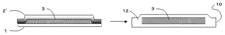
製造方法の第1の手段としては、互いに、ガラス基材を被覆できる程度の面積を有し、かつ、互いに実質的に同一の樹脂からなる第1および第2の樹脂基材によって該ガラス基材を被覆する。その際、ガラス基材の外周全てに、第1および第2の樹脂基材ともに、接着代を設けるようにガラス基材が配置され、両樹脂基材の接着代同士を重ね合わせて、溶剤接着により封止する。具体的に例示すると、
ア)第1の樹脂基材の表面上に、ガラス基材を配置した後、第2の樹脂基材を、第1の樹脂基材との間にガラス基材を挟み込むように被覆せしめ、接着代の部分に形成された両樹脂基材同士の間隙の全てに、前記有機溶剤又は前記樹脂溶液を浸透させることで接着代同士を溶剤接着し、封止する方法(図3参照)、
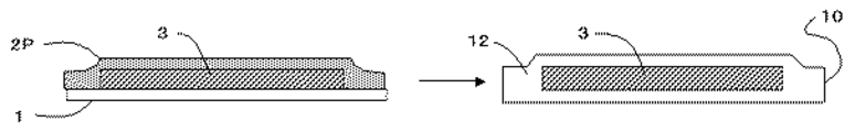
イ)第1の樹脂基材表面にガラス基材を配置する。次いで、予め、ガラス基材と接触する表面全面に前記有機溶剤又は前記樹脂溶液をコーティングした第2の樹脂基材で、ガラス基材を被覆し、両樹脂基材の接着代同士を溶剤接着し、封止する方法(図4参照)、
ウ)第1の樹脂基材の表面全面に、予め、前記有機溶剤又は前記樹脂溶液をコーティングした後、コーティングした表面にガラス基材を配置し、次いで、第2の樹脂基材で被覆し、両樹脂基材の接着代同士を溶剤接着し、封止する方法(図5参照)、
エ)第1及び第2の樹脂基材の表面全面に、予め、前記有機溶剤又は前記樹脂溶液をコーティングした後、両樹脂基材のコーティング処理した表面でガラス基材を挟み込むように配置し、次いで、両樹脂基材の接着代同士を溶剤接着させ、封止する方法(図6参照)
が挙げられる。
Hereinafter, the manufacturing method of the display substrate using the solvent bonding of the present invention will be specifically described.
As a first means of the manufacturing method, the glass base material is composed of the first and second resin base materials which have an area enough to cover the glass base material and are made of substantially the same resin. Coating. At that time, the glass base material is arranged so as to provide an adhesion allowance for both the first and second resin base materials on the entire outer periphery of the glass base material, and the adhesive allowances of both the resin base materials are overlapped to form a solvent adhesion. Seal with. Specifically,
A) After the glass substrate is disposed on the surface of the first resin substrate, the second resin substrate is covered with the glass substrate so as to be sandwiched between the first resin substrate and bonded. A method of solvent-bonding and sealing the bonding margin by infiltrating the organic solvent or the resin solution into all the gaps between the resin base materials formed in the portion of the margin (see FIG. 3),
B) A glass substrate is disposed on the surface of the first resin substrate. Next, the glass substrate is covered with a second resin substrate that is previously coated with the organic solvent or the resin solution on the entire surface in contact with the glass substrate, and the bonding margin of both resin substrates is solvent-bonded. , Sealing method (see FIG. 4),
C) After coating the organic solvent or the resin solution on the entire surface of the first resin substrate in advance, a glass substrate is placed on the coated surface, and then coated with the second resin substrate; A method of solvent-bonding and sealing the bonding allowance of both resin substrates (see FIG. 5),
D) Preliminarily coating the organic solvent or the resin solution on the entire surface of the first and second resin substrates, and then placing the glass substrate between the coated surfaces of both resin substrates, Next, a method in which the bonding allowance of both resin substrates is solvent-bonded and sealed (see FIG. 6)
Is mentioned.
また、製造方法の第2の手段として、第2の樹脂基材による被覆を、有機溶剤に溶解させた樹脂溶液を塗装することで、行うことができる。具体的には、
オ)第1の樹脂基材の上に、ガラス基材を配置した後、ガラス基材の上方向から、前記樹脂溶液をコーティングし、ガラス基材、第1の樹脂基材の接着代を塗装し、塗装された樹脂溶液を乾燥、膜化することによって第2の樹脂基材を形成すると同時に、第1の樹脂基材の接着代部が溶剤接着させ、封止する方法(図7参照)
を挙げることができる。
Further, as a second means of the production method, the coating with the second resin base material can be performed by painting a resin solution dissolved in an organic solvent. In particular,
E) After the glass substrate is arranged on the first resin substrate, the resin solution is coated from above the glass substrate, and the glass substrate and the first resin substrate are bonded together. Then, the coated resin solution is dried and formed into a film to form the second resin base material, and at the same time, the bonding margin of the first resin base material is solvent-bonded and sealed (see FIG. 7).
Can be mentioned.
前記のように、溶剤接着には有機溶剤または樹脂溶液のいずれも用いることができるが、ガラス基材縁部の欠陥を改善し、割れにくくさせるため樹脂溶液を用いるのが好ましい。樹脂溶液の濃度は特に制限はないが、0.01〜30重量%が好ましく、0.1〜10重量%がより好ましい。0.01重量%以上であるとガラス基材縁部の欠陥を改善し、割れにくくさせるのに効果があり、他方30重量%以下であると、樹脂溶液の粘度が低くなり好ましい。 As described above, either an organic solvent or a resin solution can be used for solvent adhesion, but it is preferable to use a resin solution in order to improve defects at the edge of the glass substrate and make it difficult to break. The concentration of the resin solution is not particularly limited, but is preferably 0.01 to 30% by weight, more preferably 0.1 to 10% by weight. If it is 0.01% by weight or more, it is effective for improving defects at the edge of the glass substrate and making it difficult to break. On the other hand, if it is 30% by weight or less, the viscosity of the resin solution is preferably lowered.
有機溶剤又は樹脂溶液に使用する溶剤は、樹脂基材における接着面が溶解ないし膨潤すれば特に制限はないが、予め製造した樹脂基材に対する溶解速度が低い溶剤を使用することが好ましい。溶解速度が速いと、接着・封止する過程で、樹脂基材の表面に、表面荒れ等が生じる場合があり、操作が煩雑になるため、好ましくない。溶解速度は、溶解度の高い溶媒と溶解度の低い溶媒を混合し、溶解速度を適度に調整した混合溶媒を用いることもでき、これは使用する樹脂基材に対して、予備実験を行うことによって適宜決定することができる。 The solvent used for the organic solvent or the resin solution is not particularly limited as long as the adhesive surface in the resin substrate dissolves or swells, but it is preferable to use a solvent having a low dissolution rate with respect to the resin substrate manufactured in advance. If the dissolution rate is high, surface roughness or the like may occur on the surface of the resin base material in the process of bonding and sealing, which is not preferable because the operation becomes complicated. For the dissolution rate, a solvent having a high solubility and a solvent having a low solubility are mixed, and a mixed solvent in which the dissolution rate is appropriately adjusted can be used. This can be appropriately performed by conducting a preliminary experiment on the resin substrate to be used. Can be determined.
有機溶剤又は樹脂溶液を熱処理し、有機溶剤自体または樹脂溶液に含まれる溶剤を揮発させる方法として、自然乾燥のみでなく、伝導熱、輻射熱、高周波誘導、熱プレス、真空プレスなどを用いてもよい。これらの中でも、熱プレス、真空プレスがディスプレイ用基板の平滑性が良好となるため好ましい。 As a method of heat-treating the organic solvent or the resin solution and volatilizing the organic solvent itself or the solvent contained in the resin solution, not only natural drying but also conductive heat, radiant heat, high frequency induction, heat press, vacuum press, etc. may be used. . Among these, a heat press and a vacuum press are preferable because the smoothness of the display substrate is improved.
また、各種用途に応じて、他の層を付加してもよく、例えば、円偏光フィルタ、光拡散層、各種レンズフィルム、色純度の改善や色調変換のための各種カラーフィルター、電極、保護膜等が挙げられる。 In addition, other layers may be added according to various applications, such as a circularly polarizing filter, a light diffusion layer, various lens films, various color filters for improving color purity and color conversion, electrodes, and protective films. Etc.
本発明のディスプレイ基板は、例えば、液晶ディスプレイ、有機ELディスプレイ、プラズマディスプレイ、フィールドエミッションディスプレイ、電子ペーパー等のフラットパネルディスプレイ用基板等に好適に使用される。また、液晶ディスプレイ、信号、ネオンサイン等のバックライト用基板としても利用できる。 The display substrate of the present invention is suitably used for a flat panel display substrate such as a liquid crystal display, an organic EL display, a plasma display, a field emission display, and electronic paper. It can also be used as a backlight substrate for liquid crystal displays, signals, neon signs, and the like.
以下、本発明を実施例により説明するが、本発明は実施例により限定されるものではない。
[水蒸気透過度の測定]
JIS Z0208(カップ法)に準拠して温度40℃、相対湿度90%の条件で測定した。尚、本評価の測定限界は0.03g/m2/dayである。
[耐屈曲性試験]
60mmφの棒に1回巻きつけた後、ガラス基材の亀裂の有無を目視にて確認した。
EXAMPLES Hereinafter, although an Example demonstrates this invention, this invention is not limited by an Example.
[Measurement of water vapor permeability]
Measurement was performed under conditions of a temperature of 40 ° C. and a relative humidity of 90% in accordance with JIS Z0208 (cup method). The measurement limit of this evaluation is 0.03 g / m 2 / day.
[Flexibility test]
After winding once around a 60 mmφ rod, the glass substrate was visually checked for cracks.
製造例1(ガラス基材の表面処理)
厚さ50μmの無アルカリガラス(松浪硝子工業社製 AF−45 10cm角サイズ)にプライマー(十条ケミカル社製 プライマーL)をスピンコータ−で塗布した後、常温乾燥し、ガラス基材の表面処理を行った。次いで、該表面処理を施した裏面にも、同様の表面処理を行った。
Production Example 1 (surface treatment of glass substrate)
A primer (Jujo Chemical Co., Ltd., Primer L) was applied to a 50 μm-thick alkali-free glass (manufactured by Matsunami Glass Industrial Co., Ltd., AF-45 10 cm square size) with a spin coater, followed by drying at room temperature and surface treatment of the glass substrate. It was. Next, the same surface treatment was performed on the back surface subjected to the surface treatment.
製造例2(樹脂基材の作製)
トルエンにて30重量%となるように調整したポリシクロオレフィン(JSR社製 ARTON)溶液を、厚み100μmのポリシクロオレフィンフィルム(JSR社製 ARTON 12cm角サイズ)にスピンコータ−で塗布し、100℃で60分減圧乾燥を行い、樹脂基材を作成した。
Production Example 2 (Production of resin base material)
A polycycloolefin (ARTON manufactured by JSR) solution adjusted to 30% by weight with toluene was applied to a 100 μm thick polycycloolefin film (ARTON 12 cm square size manufactured by JSR) with a spin coater at 100 ° C. The resin base material was created by drying under reduced pressure for 60 minutes.
実施例1(フィルム基板の作製)
製造例1で得られたガラス基材を、製造例2で得られた樹脂基材で塗布処理を行った面がガラス基材と接触し、かつガラス基材全ての端部を越えて、樹脂基材の過剰部分があるように配置した。その後、150℃で2分真空プレスを行い、本発明のフィルム基板を作製した。次いで、上述の方法により、水蒸気透過度、耐屈曲性試験の評価を行った。結果を表1に示す。
Example 1 (Production of film substrate)
The glass substrate obtained in Production Example 1 was coated with the resin substrate obtained in Production Example 2 and the surface of the glass substrate was in contact with the glass substrate, and the resin exceeded the edges of all the glass substrates. The substrate was placed so that there was an excess part. Thereafter, vacuum pressing was performed at 150 ° C. for 2 minutes to produce the film substrate of the present invention. Subsequently, the water vapor permeability and the bending resistance test were evaluated by the above-described methods. The results are shown in Table 1.
比較例1
ガラス基材を用いない以外は実施例1と同様にして、フィルム基板を作製した。結果を表1に示す。
Comparative Example 1
A film substrate was produced in the same manner as in Example 1 except that the glass substrate was not used. The results are shown in Table 1.
比較例2
両面セパレーターで挟持された市販のアクリル系接着フィルム(12cm角サイズ)の一方のセパレーターを剥離し、露出した接着面を厚み100μmのポリシクロオレフィンフィルム(JSR社製 ARTON 12cm角サイズ)にロールラミネータを用いて貼着し、アクリル系接着フィルム/ポリシクロオレフィンフィルムの複合体フィルムを得た。次いで、前記複合フィルムの他方のセパレーターを剥離し、露出した接着面を製造例1で得られたガラス層にロールラミネータを用いて貼着した。その後、前記ガラス層の他方に前記と同様に作製したポリシクロオレフィンフィルム/アクリル系接着フィルムを貼着し、フィルム基板を作製した。結果を表1に示す。
Comparative Example 2
One separator of a commercially available acrylic adhesive film (12 cm square size) sandwiched between double-sided separators is peeled off, and a roll laminator is applied to a polycycloolefin film (ARTON 12 cm square size manufactured by JSR) with a 100 μm thick exposed adhesive surface. The composite film of an acrylic adhesive film / polycycloolefin film was obtained. Next, the other separator of the composite film was peeled off, and the exposed adhesive surface was attached to the glass layer obtained in Production Example 1 using a roll laminator. Thereafter, a polycycloolefin film / acrylic adhesive film prepared in the same manner as described above was attached to the other glass layer to prepare a film substrate. The results are shown in Table 1.
比較例3
製造例1で得られたガラス基材をそのまま用いた。
Comparative Example 3
The glass substrate obtained in Production Example 1 was used as it was.
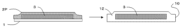
1 第1の樹脂基材
1’ 樹脂溶液で表面をコーティングした第1の樹脂基材
2 第2の樹脂基材
2’ 樹脂溶液で表面をコーティングした第2の樹脂基材
2E 第2の樹脂基材の接着代部分
2P 第2の樹脂基材の前駆体である樹脂溶液
3 ガラス基材
3’ 封止されたガラス基材(透視図)
4 第1、第2の樹脂基基材の間隙に浸透させた有機溶剤 または 樹脂溶液
10 (封止された)端面
12 第1と第2の樹脂基材を封止した樹脂基材(ディスプレイ基板の外被)
DESCRIPTION OF
4 Organic solvent or
Claims (11)
前記第1の樹脂基材と前記第2の樹脂基材との間にガラス基板を挟み込むように両樹脂基材の接着代同士を重ね合わせて、前記第1の樹脂基材と前記第2の樹脂基材とでガラス基板を被覆し、前記第1の樹脂基材および第2の樹脂基材と同一の樹脂により、ガラス基板を封止するフレキシブル基板の製造方法。 The glass substrate is arranged so as to provide an adhesion allowance along with the first and second resin base materials made of substantially the same resin on the entire outer periphery of the glass substrate,
The first resin base material and the second resin base material are overlapped with each other so that the glass substrate is sandwiched between the first resin base material and the second resin base material. the glass substrate coated with a resin substrate, by the first resin substrate and the second resin substrate and the same resin, method of manufacturing a flexible substrate for sealing the glass substrates.
Priority Applications (1)
| Application Number | Priority Date | Filing Date | Title |
|---|---|---|---|
| JP2005189453A JP4982976B2 (en) | 2005-06-29 | 2005-06-29 | Flexible substrate manufacturing method and display element |
Applications Claiming Priority (1)
| Application Number | Priority Date | Filing Date | Title |
|---|---|---|---|
| JP2005189453A JP4982976B2 (en) | 2005-06-29 | 2005-06-29 | Flexible substrate manufacturing method and display element |
Publications (2)
| Publication Number | Publication Date |
|---|---|
| JP2007010834A JP2007010834A (en) | 2007-01-18 |
| JP4982976B2 true JP4982976B2 (en) | 2012-07-25 |
Family
ID=37749467
Family Applications (1)
| Application Number | Title | Priority Date | Filing Date |
|---|---|---|---|
| JP2005189453A Expired - Fee Related JP4982976B2 (en) | 2005-06-29 | 2005-06-29 | Flexible substrate manufacturing method and display element |
Country Status (1)
| Country | Link |
|---|---|
| JP (1) | JP4982976B2 (en) |
Cited By (1)
| Publication number | Priority date | Publication date | Assignee | Title |
|---|---|---|---|---|
| CN106717114A (en) * | 2014-09-18 | 2017-05-24 | 夏普株式会社 | Electroluminescence device, electronic device, and method for manufacturing electroluminescence device |
Families Citing this family (22)
| Publication number | Priority date | Publication date | Assignee | Title |
|---|---|---|---|---|
| JP5343862B2 (en) * | 2008-01-25 | 2013-11-13 | 旭硝子株式会社 | Method for producing glass resin composite |
| JP5439019B2 (en) * | 2008-04-24 | 2014-03-12 | 日東電工株式会社 | Display element substrate and manufacturing method thereof |
| JP5467792B2 (en) * | 2008-04-24 | 2014-04-09 | 日東電工株式会社 | Flexible substrate |
| KR101374400B1 (en) * | 2008-04-24 | 2014-03-17 | 닛토덴코 가부시키가이샤 | Transparent substrate |
| JP5510880B2 (en) | 2009-03-26 | 2014-06-04 | 日本電気硝子株式会社 | Glass film laminate, glass roll of the laminate, and method for producing glass roll |
| DE102009038904A1 (en) * | 2009-08-29 | 2011-03-10 | Bundesdruckerei Gmbh | Item with an Organic Light Emitting Display |
| KR101811893B1 (en) | 2009-10-22 | 2017-12-22 | 닛토덴코 가부시키가이샤 | Transparent substrate |
| JP5416546B2 (en) | 2009-10-23 | 2014-02-12 | 日東電工株式会社 | Transparent substrate |
| JP2011121320A (en) * | 2009-12-11 | 2011-06-23 | Nippon Electric Glass Co Ltd | Glass film laminate, glass roll thereof, and method for manufacturing glass roll |
| JP5615134B2 (en) * | 2010-04-30 | 2014-10-29 | 日東電工株式会社 | Manufacturing method of transparent substrate |
| KR101922603B1 (en) * | 2011-03-04 | 2018-11-27 | 가부시키가이샤 한도오따이 에네루기 켄큐쇼 | Light-emitting device, lighting device, substrate, and manufacturing method of substrate |
| TWI547369B (en) | 2011-05-27 | 2016-09-01 | 康寧公司 | Glass-plastic laminate device, processing line and methods therefor |
| JP2013123833A (en) * | 2011-12-14 | 2013-06-24 | Nippon Zeon Co Ltd | Laminate of inorganic glass and resin film, and method for manufacturing the same |
| KR20150027067A (en) | 2012-05-29 | 2015-03-11 | 닛토덴코 가부시키가이샤 | Adhesive, and transparent substrate using same |
| EP2857473A4 (en) | 2012-05-29 | 2016-01-20 | Nitto Denko Corp | Adhesive, and transparent substrate using same |
| TWI599478B (en) | 2012-10-19 | 2017-09-21 | Nitto Denko Corp | Thin glass long body |
| JP6033096B2 (en) | 2013-01-17 | 2016-11-30 | 日東電工株式会社 | Thin glass long body |
| CN105009689B (en) | 2013-03-08 | 2018-06-22 | 日本先锋公司 | Light-emitting component |
| JP2016039135A (en) * | 2014-08-06 | 2016-03-22 | 三菱化学株式会社 | Flexible substrate, organic el element using the same, and organic el luminaire |
| JP2016100172A (en) * | 2014-11-20 | 2016-05-30 | パイオニア株式会社 | Light-emitting device and method for manufacturing light-emitting device |
| JP6743420B2 (en) * | 2016-03-01 | 2020-08-19 | 三菱ケミカル株式会社 | Flexible substrate, electronic device manufacturing substrate, and electronic device |
| JP2022028479A (en) | 2020-08-03 | 2022-02-16 | 日東電工株式会社 | Multilayer structure |
Family Cites Families (10)
| Publication number | Priority date | Publication date | Assignee | Title |
|---|---|---|---|---|
| JPS6259040A (en) * | 1985-03-14 | 1987-03-14 | 旭硝子株式会社 | Manufacture of laminate |
| FR2706884B1 (en) * | 1993-06-22 | 1995-08-25 | Saint Gobain Vitrage Int | |
| JPH10119184A (en) * | 1996-10-16 | 1998-05-12 | Asahi Glass Co Ltd | Transparent laminate |
| GB2335884A (en) * | 1998-04-02 | 1999-10-06 | Cambridge Display Tech Ltd | Flexible substrates for electronic or optoelectronic devices |
| JP2001244077A (en) * | 2000-03-01 | 2001-09-07 | Fuji Photo Film Co Ltd | Organic light emitting device |
| JP2003186403A (en) * | 2001-12-21 | 2003-07-04 | Gunze Ltd | Foamed heat-shrinkable film for drink container label and cylindrical drink container with the label |
| JP2003337549A (en) * | 2002-05-17 | 2003-11-28 | Asahi Glass Co Ltd | Substrate for flat panel display, display device, organic electroluminescence element, and liquid crystal display element |
| JP2004079432A (en) * | 2002-08-21 | 2004-03-11 | Nitto Denko Corp | Transparent gas barrier member and organic electroluminescent element using it |
| JP4193646B2 (en) * | 2003-09-10 | 2008-12-10 | セイコーエプソン株式会社 | Welding method |
| JP4546178B2 (en) * | 2003-10-23 | 2010-09-15 | 日東電工株式会社 | Optical resin sheet, liquid crystal cell substrate including the optical resin sheet, liquid crystal display device, image display device substrate, and image display device |
-
2005
- 2005-06-29 JP JP2005189453A patent/JP4982976B2/en not_active Expired - Fee Related
Cited By (1)
| Publication number | Priority date | Publication date | Assignee | Title |
|---|---|---|---|---|
| CN106717114A (en) * | 2014-09-18 | 2017-05-24 | 夏普株式会社 | Electroluminescence device, electronic device, and method for manufacturing electroluminescence device |
Also Published As
| Publication number | Publication date |
|---|---|
| JP2007010834A (en) | 2007-01-18 |
Similar Documents
| Publication | Publication Date | Title |
|---|---|---|
| JP4982976B2 (en) | Flexible substrate manufacturing method and display element | |
| JP6080028B2 (en) | Display device | |
| KR102241901B1 (en) | Optical laminate and display device using same | |
| KR100722342B1 (en) | Transparent Gel Self-Adhesive Agent, Transparent Gel Self-Adhesive Sheet, Optical Filter for Display | |
| JP2004259256A (en) | Transparent lamination body, pen input image display device, and image display method | |
| JP7184990B2 (en) | adhesive composition | |
| JP6934996B2 (en) | Flexible image display device and optical laminate used for it | |
| JP6858912B2 (en) | Flexible image display device and optical laminate used for it | |
| WO2021131152A1 (en) | Decorative laminated body, optical laminated body, and flexible image display device | |
| JP2007169519A (en) | Pressure-sensitive adhesive sheet | |
| WO2017014088A1 (en) | Conductive film laminate having transparent adhesive layer | |
| JP2018091967A (en) | Wavelength conversion sheet and barrier film used therefor | |
| JP5003148B2 (en) | Sealing film and display device | |
| JP7391338B2 (en) | Manufacturing method of polarizing plate | |
| JP7326733B2 (en) | Light control film, light control device | |
| TW202132877A (en) | Optical film set and liquid crystal panel | |
| JP2021196421A (en) | Dimming sheet and dimming device | |
| JP2008070685A (en) | Reflection sheet and reflector using the same | |
| US11029772B1 (en) | Transparent conductive laminated structure including a first conductive film and first adhesive layer disposed on the first conductive film and touch panel | |
| WO2021106679A1 (en) | Pressure-sensitive adhesive composition, pressure-sensitive adhesive layer, pressure-sensitive adhesive sheet, and optical laminate | |
| WO2023127932A1 (en) | Light control laminate and light control device | |
| WO2020250749A1 (en) | Pressure-sensitive adhesive composition, pressure-sensitive adhesive layer, pressure-sensitive adhesive sheet, and optical laminate | |
| WO2021131218A1 (en) | Flexible image display device and optical multilayer body used in same | |
| JP2000119048A (en) | Glass laminate and front surface plate of plasma display | |
| JP2004170804A (en) | Film lamination method and film laminate and touch panel prepared by the method |
Legal Events
| Date | Code | Title | Description |
|---|---|---|---|
| RD05 | Notification of revocation of power of attorney |
Free format text: JAPANESE INTERMEDIATE CODE: A7425 Effective date: 20080131 |
|
| A621 | Written request for application examination |
Free format text: JAPANESE INTERMEDIATE CODE: A621 Effective date: 20080215 |
|
| RD05 | Notification of revocation of power of attorney |
Free format text: JAPANESE INTERMEDIATE CODE: A7425 Effective date: 20080514 |
|
| A977 | Report on retrieval |
Free format text: JAPANESE INTERMEDIATE CODE: A971007 Effective date: 20110111 |
|
| A131 | Notification of reasons for refusal |
Free format text: JAPANESE INTERMEDIATE CODE: A131 Effective date: 20110118 |
|
| A521 | Request for written amendment filed |
Free format text: JAPANESE INTERMEDIATE CODE: A523 Effective date: 20110308 |
|
| A131 | Notification of reasons for refusal |
Free format text: JAPANESE INTERMEDIATE CODE: A131 Effective date: 20110510 |
|
| A521 | Request for written amendment filed |
Free format text: JAPANESE INTERMEDIATE CODE: A523 Effective date: 20110525 |
|
| TRDD | Decision of grant or rejection written | ||
| A01 | Written decision to grant a patent or to grant a registration (utility model) |
Free format text: JAPANESE INTERMEDIATE CODE: A01 Effective date: 20120327 |
|
| A01 | Written decision to grant a patent or to grant a registration (utility model) |
Free format text: JAPANESE INTERMEDIATE CODE: A01 |
|
| A61 | First payment of annual fees (during grant procedure) |
Free format text: JAPANESE INTERMEDIATE CODE: A61 Effective date: 20120409 |
|
| FPAY | Renewal fee payment (event date is renewal date of database) |
Free format text: PAYMENT UNTIL: 20150511 Year of fee payment: 3 |
|
| LAPS | Cancellation because of no payment of annual fees |