JP4981536B2 - Endoscopic clip device - Google Patents
Endoscopic clip device Download PDFInfo
- Publication number
- JP4981536B2 JP4981536B2 JP2007163336A JP2007163336A JP4981536B2 JP 4981536 B2 JP4981536 B2 JP 4981536B2 JP 2007163336 A JP2007163336 A JP 2007163336A JP 2007163336 A JP2007163336 A JP 2007163336A JP 4981536 B2 JP4981536 B2 JP 4981536B2
- Authority
- JP
- Japan
- Prior art keywords
- clip
- sheath
- state
- clips
- operation wire
- Prior art date
- Legal status (The legal status is an assumption and is not a legal conclusion. Google has not performed a legal analysis and makes no representation as to the accuracy of the status listed.)
- Active
Links
- 238000003780 insertion Methods 0.000 claims description 7
- 230000037431 insertion Effects 0.000 claims description 7
- 210000004400 mucous membrane Anatomy 0.000 description 9
- 210000004877 mucosa Anatomy 0.000 description 6
- 238000000034 method Methods 0.000 description 3
- 230000000740 bleeding effect Effects 0.000 description 2
- 210000000078 claw Anatomy 0.000 description 2
- 239000002184 metal Substances 0.000 description 2
- 238000001356 surgical procedure Methods 0.000 description 2
- 238000013459 approach Methods 0.000 description 1
- 230000008878 coupling Effects 0.000 description 1
- 238000010168 coupling process Methods 0.000 description 1
- 238000005859 coupling reaction Methods 0.000 description 1
- 239000011347 resin Substances 0.000 description 1
- 229920005989 resin Polymers 0.000 description 1
- 239000000126 substance Substances 0.000 description 1
- BFKJFAAPBSQJPD-UHFFFAOYSA-N tetrafluoroethene Chemical group FC(F)=C(F)F BFKJFAAPBSQJPD-UHFFFAOYSA-N 0.000 description 1
- 210000001519 tissue Anatomy 0.000 description 1
Images


Landscapes
- Surgical Instruments (AREA)
- Endoscopes (AREA)
Description
この発明は内視鏡用クリップ装置に関し、特に、シースの先端内に複数のクリップが直列に連結配置されたいわゆる連発型の内視鏡用クリップ装置に関する。 The present invention relates to an endoscopic clip device, and more particularly to a so-called continuous-type endoscopic clip device in which a plurality of clips are connected in series in the distal end of a sheath.
連発型の内視鏡用クリップ装置においては一般に、内視鏡の処置具挿通チャンネルに挿脱されるシースの先端内に複数のクリップが各々窄まった状態で直列に連結された状態に配置され、シース内に軸線方向に進退自在に配置された操作ワイヤにより複数のクリップをシースの先端から順次押し出して、最先端に位置するクリップを一旦開いた後に閉じさせてから最先端のクリップと次のクリップとの連結を解くことができるように構成されている(例えば、特許文献1)。
上述のような連発型の内視鏡用クリップ装置においては、患部粘膜に対してクリッピングされるクリップと操作ワイヤとの間に複数のクリップが介在していて、操作ワイヤの進退動作がそのような複数のクリップにより伝達されて先端のクリップを動作させる構成になっている。 In the continuous endoscopic clip device as described above, a plurality of clips are interposed between the clip clipped to the affected mucous membrane and the operation wire, and the operation wire advances and retreats as described above. It is configured to operate the clip at the tip transmitted by a plurality of clips.
しかし、例えば先端のクリップが患部粘膜に適正にクリッピングできなかった状態で粘膜に食い付いたまま離れなくなったり、先端のクリップが患部粘膜にうまくクリッピングできた後に、その後に位置するクリップとの連結が外れなくなったりすると、いわゆる「にっちもさっちもいかない」状態になって、場合によっては外科的な対処が必要になってしまうおそれがある。 However, for example, after the clip at the tip could not be properly clipped to the affected mucous membrane, it stuck to the mucosa, or after the clip at the tip could be clipped successfully to the affected mucosa, the connection with the clip located after that If it does not come off, it will be in a so-called “neither or neither” state, and in some cases, a surgical measure may be required.
本発明は、クリッピング処置の最中にクリップが意図した通りに動作しなくなって、にっちもさっちもいかなくなった場合等に、外科的な処置をすることなくその状況を解消することができる内視鏡用クリップ装置を提供することを目的とする。 The present invention provides an endoscopic clip that can eliminate the situation without performing a surgical procedure when the clip does not operate as intended during the clipping procedure, and when the clip stops working. An object is to provide an apparatus.
上記の目的を達成するため、本発明の内視鏡用クリップ装置は、内視鏡の処置具挿通チャンネルに挿脱されるシースの先端内に複数のクリップが各々窄まった状態で直列に連結された状態に配置され、シース内に軸線方向に進退自在に配置された操作ワイヤにより複数のクリップをシースの先端から順次押し出して、最先端に位置するクリップを一旦開いた後に閉じさせてから最先端のクリップと次のクリップとの連結を解くことができるように構成された内視鏡用クリップ装置において、各クリップと操作ワイヤを各々導電性の部材により形成してそれらを電気的に導通する状態に連結し、シースを電気絶縁性の部材により形成すると共に、操作ワイヤの基端を高周波電源に接続するための接続手段を設けたものである。 In order to achieve the above object, an endoscope clip device according to the present invention is connected in series with a plurality of clips constricted in the distal end of a sheath inserted into and removed from a treatment instrument insertion channel of an endoscope. A plurality of clips are sequentially pushed out from the distal end of the sheath by an operation wire that is arranged in the sheathed state so as to be able to advance and retreat in the axial direction in the sheath. In an endoscopic clip device configured to be able to release the connection between a tip clip and a next clip, each clip and an operation wire are each formed of a conductive member and are electrically connected to each other. In addition to being connected to the state, the sheath is formed of an electrically insulating member, and connection means for connecting the proximal end of the operation wire to a high-frequency power source is provided.
なお、各クリップの後端部付近に熱破壊され易い脆弱部が形成されていてもよく、その脆弱部が、クリップの断面積を局部的に他の部分より小さくすることにより形成されていて、機械的にも脆弱であってもよい。 In addition, the weak part which is easy to be thermally destroyed may be formed near the rear end part of each clip, and the weak part is formed by making the cross-sectional area of the clip smaller than other parts locally, It may be mechanically fragile.
本発明によれば、各クリップと操作ワイヤを各々導電性の部材により形成してそれらを電気的に導通する状態に連結し、シースを電気絶縁性の部材により形成すると共に、操作ワイヤの基端を高周波電源に接続するための接続手段を設けたことにより、クリッピング処置の最中にクリップが意図した通りに動作しなくなって、にっちもさっちもいかなくなった場合等に、クリップに高周波電流を通電することにより、外科的な処置をすることなくその状況を解消することができる。 According to the present invention, each clip and the operation wire are each formed of a conductive member, and are connected to a state where they are electrically connected, and the sheath is formed of an electrically insulating member, and the proximal end of the operation wire By providing a connection means for connecting to a high-frequency power supply, if the clip does not operate as intended during the clipping procedure, and if it stops working at all, the high-frequency current is applied to the clip. The situation can be resolved without surgical treatment.
内視鏡の処置具挿通チャンネルに挿脱されるシースの先端内に複数のクリップが各々窄まった状態で直列に連結された状態に配置され、シース内に軸線方向に進退自在に配置された操作ワイヤにより複数のクリップをシースの先端から順次押し出して、最先端に位置するクリップを一旦開いた後に閉じさせてから最先端のクリップと次のクリップとの連結を解くことができるように構成された内視鏡用クリップ装置において、各クリップと操作ワイヤを各々導電性の部材により形成してそれらを電気的に導通する状態に連結し、シースを電気絶縁性の部材により形成すると共に、操作ワイヤの基端を高周波電源に接続するための接続手段を設け、各クリップの後端部付近に熱破壊され易い脆弱部を形成する。 A plurality of clips are placed in a state of being connected in series in the distal end of the sheath inserted into and removed from the treatment instrument insertion channel of the endoscope, and are arranged in the sheath so as to be movable forward and backward in the axial direction. It is configured so that multiple clips can be sequentially pushed out from the tip of the sheath with the operation wire, and the clip located at the foremost position can be opened and closed and then the connection between the foremost clip and the next clip can be released. In addition, in the endoscope clip device, each clip and the operation wire are each formed by a conductive member and are connected to a state where they are electrically connected, and the sheath is formed by an electrically insulating member, and the operation wire A connecting means for connecting the base end of the clip to a high frequency power source is provided, and a fragile portion easily damaged by heat is formed in the vicinity of the rear end portion of each clip.
以下、図面を参照して本発明の実施例を説明する。
図1は本発明の実施例の内視鏡用クリップ装置を示しており、1は、例えば四フッ化エチレン樹脂チューブ等のような電気絶縁性の可撓性チューブからなる可撓性のシースであり、図示されていない内視鏡の処置具挿通チャンネル内に挿脱自在である。
Embodiments of the present invention will be described below with reference to the drawings.
FIG. 1 shows an endoscopic clip device according to an embodiment of the present invention, and 1 is a flexible sheath made of an electrically insulating flexible tube such as a tetrafluoroethylene resin tube. Yes, it can be inserted into and removed from a treatment instrument insertion channel of an endoscope (not shown).
シース1の先端に取り付けられた先端口金2内には、ばね性のあるCリング3が配置されている。Cリング3は、軸線方向への移動は阻止されているが、先端口金2内で押し広げる状態に弾性変形させることができる。
In the
シース1内には、シース1の基端側に連結された操作部30から任意に進退操作することができる導電金属製の操作ワイヤ4が挿通配置されていて、その先端に接続管5を介して連結環6が固着連結されている。
In the
シース1の先端近傍内には導電性の金属部材で形成された複数のクリップ10が互いに電気的に導通した状態に直列に配置されている。各クリップ10と操作ワイヤ4との間も、接続管5と連結環6を介して電気的に導通している。
In the vicinity of the distal end of the
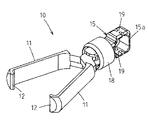
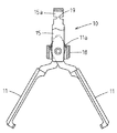
クリップ10は、単体の状態とそれを分解して示す図2及び図3に示されるように、個別に独立して形成された一対の開閉アーム11を有していて、各開閉アーム11の先端に形成された先端爪部12は内方に向かってあい対向する状態に曲げられている。
As shown in FIGS. 2 and 3, the
一対の開閉アーム11の後端付近には各々軸孔13が形成されていて、そこに通された支軸14を中心にして、一対の開閉アーム11が前方に向かって嘴状に自由に開閉することができる。
15は、操作ワイヤ4との連結を司る環状の連結環15aが後端部に形成された連結用尾部であり、開閉アーム11の後端部付近を緩く挟み込む形状の一対の平行板部分に、支軸14が通される支持孔16が形成されている。なお、連結用尾部15は、操作ワイヤ4に直接連結されるのではなく、後方のクリップ10や後述する連結用クリップ20等を介して操作ワイヤ4と連結される。
15 is a connection tail portion formed at the rear end portion of an
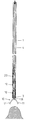
18は、一対の開閉アーム11を強制的に開閉させるための締め環であり、待機状態においては、図4に示されるように開閉アーム11の基部付近に緩く被嵌された状態になっている。
そして、図5に示されるように締め環18を開閉アーム11に対して相対的に後方に移動させると、開閉アーム11の後端に形成された駆動カム11aに締め環18がぶつかって、開閉アーム11が開いた状態にされる。
Then, as shown in FIG. 5, when the
クリップ10がシース1の先端から押し出される際には、締め環18の先端面が一旦Cリング3に当接してその位置で停止するので、このような動作が行われ、さらに強い力でクリップ10がシース1内から押されると、開閉アーム11が一杯に開いた状態のまま、締め環18がCリング3を押し広げながら先端口金2の前方に押し出される。
When the
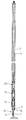
逆に、図6に示されるように締め環18が前方に移動すると、開閉アーム11が強制的に閉じた状態にされる。締め環18が先端口金2の前方に押し出された後に連結用尾部15がシース1内に引き戻されると、締め環18の後端面がCリング3に当接してこのような動作が行われる。
On the contrary, as shown in FIG. 6, when the fastening
図1に戻って、シース1の先端近傍内においては、前後に連なって位置する二つのクリップ10,10のうち前側に位置するクリップ10の連結用尾部15と、後側に位置するクリップ10の開閉アーム11とが連結されている。
Returning to FIG. 1, in the vicinity of the distal end of the
具体的には、前側のクリップ10の後端に位置する連結環15a内に、閉じた状態の後側のクリップ10の開閉アーム11の先端爪部12が差し込まれて、電気的にもつながった状態に係合している。
Specifically, the front
そのようなクリップ10の連結用尾部15には、図2及び図3に示されるように、熱破壊され易い脆弱部19が形成されている。この脆弱部19は、クリップ10の断面積を局部的にその部分だけ他の部分より数分の一程度に小さくすることにより形成されており、機械的にも脆弱である。
As shown in FIGS. 2 and 3, a
図1に示される20は、クリップ10と同じ構成であって連結環6に分離できないように連結された連結用クリップであり、他のクリップ10と同様にしてその前側に位置するクリップ10と連結されている。このようにして連結された全てのクリップ10,20がシース1内では閉じていて、シース1がこの状態で内視鏡の処置具挿通チャンネルに挿脱される。
操作部30には、シース1の基端に連結された操作部本体31にスライド操作部材32がスライド自在に係合して配置され、操作ワイヤ4の基端がそのスライド操作部材32に固定的に連結されている。したがって、操作部30においてスライド操作部材32をスライド操作することにより操作ワイヤ4がシース1内で進退する。
In the
また、スライド操作部材32には、図示されていない高周波電源コードを接続するための接続端子33が操作ワイヤ4の基端と電気的に導通して配置されている。したがって、接続端子33に高周波電源コードを接続することにより、操作ワイヤ4の基端が高周波電源に接続され、操作ワイヤ4を介してクリップ10に高周波電流を通電することができる。
In addition, a
図7〜図9は、内視鏡用クリップ装置の使用状態を示しており、シース1が処置具挿通チャンネルに通されて先端がクリッピング対象の患部に接近したら、操作ワイヤ4を基端側から押し込み操作することにより、図7に示されるように、最先端のクリップ10がシース1の先端から前方に突出して開いた状態になる。
7 to 9 show the use state of the endoscope clip device. When the
そして、シース1を前方に押し進める操作をして最先端のクリップ10の一対の開閉アーム11で患部粘膜を挟み付けた後、図8に示されるように操作ワイヤ4を基端側に牽引する操作を行うと、後方に少し引き戻された最先端のクリップ10の開閉アーム11が締め環18により強制的に閉じられた状態になって、最先端のクリップ10が患部粘膜にクリッピングされた状態になる。
Then, after pushing the
そのようにして患部粘膜に対するクリッピングが行われたら、図9に示されるように操作ワイヤ4を再び基端側から押し込み操作すると、最先端のクリップ10が閉じて患部粘膜をクリッピングした状態でシース1の前方に押し出され、引き続いて二番目のクリップ10が押し出されて開くことにより最先端のクリップ10との連結が解除され、最先端のクリップ10が体内に留置された状態になる。
When clipping is performed on the affected mucous membrane as described above, when the
そのようなクリッピング処置の最中に、例えば図8に示されるように最先端のクリップ10が患部粘膜にクリッピングされてその開閉アーム11がもはや開けない状態になった時に、最先端のクリップ10と二番目のクリップ10との連結が解けなくなって、にっちもさっちもいかなくなってしまうことがあり得る。図10は、その部分だけを抜き出して図示したものである。
During such a clipping procedure, for example, as shown in FIG. 8, when the
そのようになった場合には、接続端子33と操作ワイヤ4を介してクリップ10に高周波電流を通電すると、脆弱部19が高周波電流の通電路として格別に断面積が小さいことにより高温に発熱し、その部分が脆くなる。
In such a case, when a high-frequency current is applied to the
そこで、操作ワイヤ4を操作部30から牽引操作すれば、図11に示されるように、最先端のクリップ10の脆弱部19が二番目のクリップ10により引きちぎられた状態に壊れて、最先端のクリップ10と二番目のクリップ10との連結が解かれ、患部粘膜にクリッピングされた最先端のクリップ10が体内に無事に留置される。
Therefore, if the
ただし、本発明は上記実施例に限定されるものではなく、例えば脆弱部19を省略したものであってもよい。
その場合には、図12に最先端のクリップ10だけが抜き出して示されるように、先端のクリップ10が患部粘膜にうまくクリッピングできずに患部粘膜から離れなくなったような時に、高周波電流を通電することにより、図13に示されるように患部粘膜側が焼灼されて、出血せずに(又は、極めて少ない出血で)組織側を分断してクリップ10を患部粘膜側から安全に外すことができる。
However, this invention is not limited to the said Example, For example, the thing which abbreviate | omitted the
In that case, as shown in FIG. 12 where only the most
1 シース
4 操作ワイヤ
10 クリップ
11 開閉アーム
18 締め環
19 脆弱部
20 連結用クリップ
33 接続端子(接続手段)
DESCRIPTION OF
Claims (1)
上記各クリップと上記操作ワイヤが各々導電性の部材により形成されてそれらが電気的に導通する状態に連結され、上記シースが電気絶縁性の部材により形成されると共に、上記操作ワイヤの基端を高周波電源に接続するための接続手段が設けられ、
上記各クリップは各々、支軸を中心に前方に向かって開閉自在であって開閉方向に付勢されていない導電性の部材からなる一対の開閉アームを備えると共に、後端部分にはその後ろに位置するクリップと連結するための導電性部材からなる環状の連結環が形成されていて、その連結環内に上記後ろに位置するクリップの開閉アームが閉じた状態で係合するように構成されていることを特徴とする内視鏡用クリップ装置。 A plurality of clips are arranged in a state of being constricted in a distal end of a sheath that is inserted into and removed from a treatment instrument insertion channel of an endoscope, and are arranged so as to be movable forward and backward in the axial direction in the sheath. The plurality of clips are sequentially pushed out from the distal end of the sheath by the operation wire, and the clip located at the foremost position is once opened and then closed, and then the connection between the foremost clip and the next clip can be released. In the endoscope clip device configured as described above,
They each clip and the operating wire is formed by each conductive member is coupled to the state of electrical conduction, the sheath is formed by an electrically insulating member Rutotomoni, the proximal end of the operating wire A connection means for connecting to a high frequency power supply is provided,
Each of the clips includes a pair of opening and closing arms made of a conductive member that can be opened and closed forward about a support shaft and is not biased in the opening and closing direction. An annular connecting ring made of a conductive member for connecting to a positioned clip is formed, and the open / close arm of the clip located behind is engaged with the connecting ring in a closed state. An endoscopic clip device characterized by comprising:
Priority Applications (1)
| Application Number | Priority Date | Filing Date | Title |
|---|---|---|---|
| JP2007163336A JP4981536B2 (en) | 2007-06-21 | 2007-06-21 | Endoscopic clip device |
Applications Claiming Priority (1)
| Application Number | Priority Date | Filing Date | Title |
|---|---|---|---|
| JP2007163336A JP4981536B2 (en) | 2007-06-21 | 2007-06-21 | Endoscopic clip device |
Publications (2)
| Publication Number | Publication Date |
|---|---|
| JP2009000249A JP2009000249A (en) | 2009-01-08 |
| JP4981536B2 true JP4981536B2 (en) | 2012-07-25 |
Family
ID=40317311
Family Applications (1)
| Application Number | Title | Priority Date | Filing Date |
|---|---|---|---|
| JP2007163336A Active JP4981536B2 (en) | 2007-06-21 | 2007-06-21 | Endoscopic clip device |
Country Status (1)
| Country | Link |
|---|---|
| JP (1) | JP4981536B2 (en) |
Families Citing this family (2)
| Publication number | Priority date | Publication date | Assignee | Title |
|---|---|---|---|---|
| JP5412167B2 (en) * | 2009-04-09 | 2014-02-12 | Hoya株式会社 | Endoscopic clip device |
| US10307202B2 (en) * | 2015-12-03 | 2019-06-04 | Boston Scientific Scimed, Inc. | Electrocautery hemostasis clip |
Family Cites Families (6)
| Publication number | Priority date | Publication date | Assignee | Title |
|---|---|---|---|---|
| JPS63267345A (en) * | 1987-04-24 | 1988-11-04 | Olympus Optical Co Ltd | Clip device of living tissue |
| US5984934A (en) * | 1997-10-10 | 1999-11-16 | Applied Medical Resources Corporation | Low-profile surgical clip |
| JP2000254143A (en) * | 1999-03-08 | 2000-09-19 | Asahi Optical Co Ltd | Hemostasis clip device for endoscope |
| US7094245B2 (en) * | 2001-10-05 | 2006-08-22 | Scimed Life Systems, Inc. | Device and method for through the scope endoscopic hemostatic clipping |
| DE10334083A1 (en) * | 2003-07-26 | 2005-02-24 | Carl Stahl Gmbh | Method and device for endoscopic application of closing medical clips |
| JP4261450B2 (en) * | 2004-09-22 | 2009-04-30 | Hoya株式会社 | Endoscopic clip device |
-
2007
- 2007-06-21 JP JP2007163336A patent/JP4981536B2/en active Active
Also Published As
| Publication number | Publication date |
|---|---|
| JP2009000249A (en) | 2009-01-08 |
Similar Documents
| Publication | Publication Date | Title |
|---|---|---|
| JP4716513B2 (en) | Endoscopic clip device | |
| JP4471125B2 (en) | High frequency treatment tool | |
| JP4546424B2 (en) | Endoscopic treatment tool | |
| JP5006753B2 (en) | Endoscopic clip device | |
| US4708137A (en) | High-frequency incision device | |
| JP2008302097A (en) | Clip device for endoscope | |
| JP2000254143A (en) | Hemostasis clip device for endoscope | |
| JP5290658B2 (en) | Endoscopic treatment tool | |
| JP4981536B2 (en) | Endoscopic clip device | |
| US20150005763A1 (en) | Guide catheter with an anchoring mechanism and method for introducing guide catheter | |
| JP4414669B2 (en) | Endoscopic cutting tool | |
| JP6030010B2 (en) | Endoscopic surgical instrument | |
| JP2007283015A (en) | Clip apparatus for endoscope | |
| JP4575763B2 (en) | Endoscopic clip device | |
| JP4320194B2 (en) | Endoscopic high frequency knife | |
| JP4338457B2 (en) | Endoscopic clip device | |
| JP4589511B2 (en) | Endoscopic high frequency snare | |
| JP2005177098A (en) | Beaked treatment instrument for endoscope | |
| JP2010246663A (en) | Clip device for endoscope | |
| JP5235709B2 (en) | Endoscopic high-frequency treatment instrument | |
| JP2004097615A (en) | Hot biopsy forceps for polypectomy which is prevented from electrical leak | |
| JP2000201938A (en) | High frequency snare | |
| JP5952068B2 (en) | Endoscopic high-frequency treatment instrument | |
| JP4761597B2 (en) | Endoscopic high-frequency snare | |
| JP2015089515A (en) | Operation device for performing procedure on lumen in body |
Legal Events
| Date | Code | Title | Description |
|---|---|---|---|
| A621 | Written request for application examination |
Free format text: JAPANESE INTERMEDIATE CODE: A621 Effective date: 20100308 |
|
| A977 | Report on retrieval |
Free format text: JAPANESE INTERMEDIATE CODE: A971007 Effective date: 20120113 |
|
| A131 | Notification of reasons for refusal |
Free format text: JAPANESE INTERMEDIATE CODE: A131 Effective date: 20120118 |
|
| A521 | Request for written amendment filed |
Free format text: JAPANESE INTERMEDIATE CODE: A523 Effective date: 20120309 |
|
| TRDD | Decision of grant or rejection written | ||
| A01 | Written decision to grant a patent or to grant a registration (utility model) |
Free format text: JAPANESE INTERMEDIATE CODE: A01 Effective date: 20120404 |
|
| A01 | Written decision to grant a patent or to grant a registration (utility model) |
Free format text: JAPANESE INTERMEDIATE CODE: A01 |
|
| A61 | First payment of annual fees (during grant procedure) |
Free format text: JAPANESE INTERMEDIATE CODE: A61 Effective date: 20120420 |
|
| FPAY | Renewal fee payment (event date is renewal date of database) |
Free format text: PAYMENT UNTIL: 20150427 Year of fee payment: 3 |
|
| R150 | Certificate of patent or registration of utility model |
Ref document number: 4981536 Country of ref document: JP Free format text: JAPANESE INTERMEDIATE CODE: R150 Free format text: JAPANESE INTERMEDIATE CODE: R150 |
|
| S531 | Written request for registration of change of domicile |
Free format text: JAPANESE INTERMEDIATE CODE: R313531 |
|
| R350 | Written notification of registration of transfer |
Free format text: JAPANESE INTERMEDIATE CODE: R350 |
|
| R250 | Receipt of annual fees |
Free format text: JAPANESE INTERMEDIATE CODE: R250 |
|
| R250 | Receipt of annual fees |
Free format text: JAPANESE INTERMEDIATE CODE: R250 |
|
| R250 | Receipt of annual fees |
Free format text: JAPANESE INTERMEDIATE CODE: R250 |
|
| R250 | Receipt of annual fees |
Free format text: JAPANESE INTERMEDIATE CODE: R250 |
|
| R250 | Receipt of annual fees |
Free format text: JAPANESE INTERMEDIATE CODE: R250 |
|
| R250 | Receipt of annual fees |
Free format text: JAPANESE INTERMEDIATE CODE: R250 |
|
| R250 | Receipt of annual fees |
Free format text: JAPANESE INTERMEDIATE CODE: R250 |
|
| R250 | Receipt of annual fees |
Free format text: JAPANESE INTERMEDIATE CODE: R250 |