JP4980552B2 - Image processing method, image processing apparatus, and image processing program - Google Patents
Image processing method, image processing apparatus, and image processing program Download PDFInfo
- Publication number
- JP4980552B2 JP4980552B2 JP2003340417A JP2003340417A JP4980552B2 JP 4980552 B2 JP4980552 B2 JP 4980552B2 JP 2003340417 A JP2003340417 A JP 2003340417A JP 2003340417 A JP2003340417 A JP 2003340417A JP 4980552 B2 JP4980552 B2 JP 4980552B2
- Authority
- JP
- Japan
- Prior art keywords
- image
- image processing
- value
- radiation
- region
- Prior art date
- Legal status (The legal status is an assumption and is not a legal conclusion. Google has not performed a legal analysis and makes no representation as to the accuracy of the status listed.)
- Expired - Fee Related
Links
- 238000003672 processing method Methods 0.000 title claims description 11
- 230000005855 radiation Effects 0.000 claims description 63
- 238000003745 diagnosis Methods 0.000 claims description 23
- 238000011156 evaluation Methods 0.000 description 35
- 238000000034 method Methods 0.000 description 31
- 238000003384 imaging method Methods 0.000 description 15
- 238000006243 chemical reaction Methods 0.000 description 14
- 230000008569 process Effects 0.000 description 14
- 230000003321 amplification Effects 0.000 description 12
- 238000003199 nucleic acid amplification method Methods 0.000 description 12
- OAICVXFJPJFONN-UHFFFAOYSA-N Phosphorus Chemical compound [P] OAICVXFJPJFONN-UHFFFAOYSA-N 0.000 description 8
- 230000010354 integration Effects 0.000 description 7
- 239000006185 dispersion Substances 0.000 description 6
- 230000008859 change Effects 0.000 description 4
- 230000001186 cumulative effect Effects 0.000 description 4
- 238000001514 detection method Methods 0.000 description 4
- 238000010586 diagram Methods 0.000 description 4
- 210000004072 lung Anatomy 0.000 description 3
- 230000005540 biological transmission Effects 0.000 description 2
- 238000000605 extraction Methods 0.000 description 2
- GGCZERPQGJTIQP-UHFFFAOYSA-N sodium;9,10-dioxoanthracene-2-sulfonic acid Chemical compound [Na+].C1=CC=C2C(=O)C3=CC(S(=O)(=O)O)=CC=C3C(=O)C2=C1 GGCZERPQGJTIQP-UHFFFAOYSA-N 0.000 description 2
- 230000003187 abdominal effect Effects 0.000 description 1
- 238000010521 absorption reaction Methods 0.000 description 1
- 238000004458 analytical method Methods 0.000 description 1
- 210000000746 body region Anatomy 0.000 description 1
- 239000003990 capacitor Substances 0.000 description 1
- 230000004069 differentiation Effects 0.000 description 1
- 238000003708 edge detection Methods 0.000 description 1
- 230000003287 optical effect Effects 0.000 description 1
- 238000003825 pressing Methods 0.000 description 1
- 230000009467 reduction Effects 0.000 description 1
- 230000000241 respiratory effect Effects 0.000 description 1
- 230000004936 stimulating effect Effects 0.000 description 1
- 239000000758 substrate Substances 0.000 description 1
- 239000012780 transparent material Substances 0.000 description 1
- 238000007740 vapor deposition Methods 0.000 description 1
Images


Classifications
-
- G—PHYSICS
- G06—COMPUTING; CALCULATING OR COUNTING
- G06T—IMAGE DATA PROCESSING OR GENERATION, IN GENERAL
- G06T5/00—Image enhancement or restoration
- G06T5/90—Dynamic range modification of images or parts thereof
- G06T5/92—Dynamic range modification of images or parts thereof based on global image properties
-
- G—PHYSICS
- G06—COMPUTING; CALCULATING OR COUNTING
- G06T—IMAGE DATA PROCESSING OR GENERATION, IN GENERAL
- G06T2207/00—Indexing scheme for image analysis or image enhancement
- G06T2207/10—Image acquisition modality
- G06T2207/10116—X-ray image
- G06T2207/10121—Fluoroscopy
Landscapes
- Physics & Mathematics (AREA)
- General Physics & Mathematics (AREA)
- Engineering & Computer Science (AREA)
- Theoretical Computer Science (AREA)
- Image Processing (AREA)
- Image Analysis (AREA)
- Apparatus For Radiation Diagnosis (AREA)
Description
本発明は放射線画像を処理する際の画像処理方法および画像処理装置ならびに画像処理プログラムに関し、さらに詳しくは、診断等に適した放射線画像を得ることができる画像処理方法および画像処理装置ならびに画像処理プログラムに関する。 The present invention relates to an image processing method, an image processing apparatus, and an image processing program for processing a radiographic image, and more specifically, an image processing method, an image processing apparatus, and an image processing program capable of obtaining a radiographic image suitable for diagnosis and the like. About.
近年、放射線画像を直接デジタル画像として撮影できる装置が開発されている。たとえば、被写体に照射された放射線量を検出し、その検出量に対応して形成される放射線画像を電気信号として得る装置としては、輝尽性蛍光体を用いたディテクタを用いる方法が特開昭55-12429号公報、特開昭63-189853号公報など、多数開示されている。 In recent years, an apparatus capable of directly capturing a radiographic image as a digital image has been developed. For example, as a device for detecting a radiation dose applied to a subject and obtaining a radiographic image formed in accordance with the detected dose as an electrical signal, a method using a detector using a stimulable phosphor is disclosed in JP Many publications such as 55-12429 and JP 63-189853 are disclosed.
このような装置では、シート状の基板に輝尽性蛍光体を塗布、あるいは蒸着等によって固着したディテクタに、いったん被写体を透過した放射線を照射して輝尽性蛍光体に放射線を吸収させる。 In such an apparatus, a stimulable phosphor is applied to a sheet-like substrate or fixed to the detector by vapor deposition or the like, and once irradiated with radiation transmitted through the subject, the stimulable phosphor absorbs the radiation.
その後、この輝尽性蛍光体を光または熱エネルギ−で励起することにより、この輝尽性蛍光体が上記吸収によって蓄積している放射線エネルギ−を蛍光として放射させ、この蛍光を光電変換して画像信号を得るようにしている。 Thereafter, the stimulable phosphor is excited by light or heat energy, and the stimulating phosphor emits radiation energy accumulated by the absorption as fluorescence, and the fluorescence is photoelectrically converted. An image signal is obtained.
一方、照射された放射線の強度に応じた電荷を光導電層に生成し、生成された電荷を二次元的に配列された複数のコンデンサに蓄積し、それら蓄積された電荷を取り出すことにより得られる放射線画像検出装置が提案されている。 On the other hand, a charge corresponding to the intensity of irradiated radiation is generated in the photoconductive layer, the generated charge is accumulated in a plurality of capacitors arranged two-dimensionally, and the accumulated charges are taken out. A radiation image detection apparatus has been proposed.
このような放射線画像検出装置では、フラットパネルディテクタ(FPD)と呼ばれるものを使用している。この種のFPDは、特開平9-90048号公報に記載されているように、照射された放射線強度に応じた蛍光を発する蛍光体と、蛍光体から発する蛍光を直接または縮小光学系を介して受光して光電変換を行うフォトダイオードやCCDのような光電変換素子の組み合わせによって実現されるものが知られている。 Such a radiation image detection apparatus uses what is called a flat panel detector (FPD). As described in JP-A-9-90048, this type of FPD includes a phosphor that emits fluorescence corresponding to the intensity of irradiated radiation, and fluorescence emitted from the phosphor directly or through a reduction optical system. Known is a combination of a photodiode that receives light and performs photoelectric conversion, or a combination of photoelectric conversion elements such as a CCD.
また特開平6-342098号公報に記載されているように、照射された放射を直接電荷に変換するものも知られている。 In addition, as described in Japanese Patent Laid-Open No. 6-342098, there is also known one that directly converts irradiated radiation into electric charges.
これらの放射線画像検出装置では、取得した画像に対して、診断に適した画像となるよう、階調変換処理やエッジ強調処理などの画像処理を行うのが一般的である。 In these radiological image detection apparatuses, it is common to perform image processing such as gradation conversion processing and edge enhancement processing on an acquired image so that the image is suitable for diagnosis.
なお、このようにして得られた画像データに基づく放射線画像を表示したり出力する場合、撮影条件の変動を受けることなく見やすい放射線画像となるように画像処理が行われている。 Note that when displaying or outputting a radiographic image based on the image data obtained in this way, image processing is performed so that the radiographic image is easy to see without being subjected to fluctuations in imaging conditions.
このため、放射線画像の所望の領域内の画像データの累積ヒストグラムを求めたのち、この累積ヒストグラムが所定の割合となるデータレベルを基準信号値と設定して画像処理を行うことが、以下の特許文献1に記載されている。
Therefore, after obtaining a cumulative histogram of image data in a desired region of a radiographic image, image processing is performed by setting a data level at which the cumulative histogram is a predetermined ratio as a reference signal value. It is described in
また、高信号値領域と低信号値領域の分布状態に基づいて、画像処理条件を定めて、適切な画像処理を行うことが、以下の特許文献2に記載されている。
ところで、放射線画像では、被写体の撮影部位によって高濃度領域(放射線透過量の大きい領域)と低濃度領域(放射線透過量の小さい領域)の割合が大きく異なる。また、被写体の状態、例えば患者の呼吸状態によって肺野内の濃度が著しく異なるものとされる。 By the way, in the radiographic image, the ratio of the high density region (region with a large amount of radiation transmission) and the low density region (region with a small amount of radiation transmission) differ greatly depending on the imaging region of the subject. In addition, the concentration in the lung field varies significantly depending on the state of the subject, for example, the respiratory state of the patient.
このため、放射線画像の所望の領域内の画像データの累積ヒストグラムを求めたのち、この累積ヒストグラムが所定の割合となるデータレベルを基準信号値と設定して画像処理を行う場合(特開平6−61325号公報)には、高濃度領域と低濃度領域の割合の違いによっては、診断等に適した見やすい放射線画像を得ることができない恐れがある。 For this reason, after obtaining a cumulative histogram of image data in a desired region of a radiographic image, image processing is performed by setting a data level at which the cumulative histogram has a predetermined ratio as a reference signal value (Japanese Patent Laid-Open No. 6-1994). No. 61325) may not be able to obtain an easy-to-see radiation image suitable for diagnosis or the like depending on the difference in the ratio between the high density region and the low density region.
例えば、基準信号値が所定の濃度となるように階調処理を行った場合、低濃度領域が支配的であるときには基準信号値が低い値となるので全体的に高濃度な画像となり、高濃度領域が支配的であるときには基準信号値が高い値となるので全体的に低濃度な画像となる。 For example, when gradation processing is performed so that the reference signal value has a predetermined density, when the low density region is dominant, the reference signal value becomes a low value, so that an overall high density image is obtained. When the region is dominant, the reference signal value is high, so that the image has a low density as a whole.
しかし、例えば肋骨のような部位では上部肋骨部(高濃度領域の多い肺野部分が含まれる)や下部肋骨部(高濃度領域の少ない腹部部分が含まれる)を撮影して診断を行う場合でも、診断で必要とされる部分は高濃度領域と低濃度領域の両方にまたがっており、画像全体の濃度が低濃度あるいは高濃度に偏ることは、診断を行う上で好ましくない。 However, for example, in the case of a part such as a rib, even when imaging is performed by imaging the upper rib part (including a lung field part having a high concentration area) and the lower rib part (including an abdominal part having a low high concentration area). The portion required for diagnosis extends over both the high density region and the low density region, and it is not preferable for the diagnosis that the density of the entire image is biased to the low density or the high density.
すなわち、従来は、画像処理のパラメータを決定するために様々な手法が提案されているが、その手法は画像内の特定領域(関心領域など)の信号値やヒストグラムから決定される信号値あるいはパラメータとして一意的に与えるなどのように決定され、得られる領域やパラメータが不適切な場合、不適切な画像処理が得られる場合があった。 That is, conventionally, various methods have been proposed for determining image processing parameters, but the method is based on signal values or parameters determined from a signal value or a histogram of a specific region (region of interest) in the image. If the obtained area or parameter is inappropriate, there is a case where inappropriate image processing is obtained.
本発明は以上のような課題に鑑みてなされたものであって、画像処理条件決定の失敗により診断が困難となる状況の発生を防止し、いかなる場合であっても適切な条件あるいは適切に近い条件で画像処理することが可能な画像処理方法および画像処理装置ならびに画像処理プログラムを実現することを目的とする。 The present invention has been made in view of the problems as described above, and prevents the occurrence of a situation in which diagnosis is difficult due to failure in determining image processing conditions, and in any case appropriate conditions or close to appropriate conditions. An object is to realize an image processing method, an image processing apparatus, and an image processing program capable of performing image processing under conditions.
すなわち、前記した課題を解決は、以下に列記する発明により解決される。 That is, the above-described problems can be solved by the inventions listed below.
(1)請求項1記載の発明は、被写体を透過した放射線の照射線量に応じた信号値を有する放射線画像に対し、診断に適した画像を得るためにルックアップテーブルにより信号値を変換して階調処理を行う画像処理方法であって、前記放射線画像のエッジ領域の各画素について、信号値に対応する前記ルックアップテーブルの傾きに基づく値をそれぞれ算出し、その総和が最大になるように、前記ルックアップテーブルのパラメータを決定するパラメータ決定ステップと、前記パラメータ決定ステップで決定された前記パラメータで定義される前記ルックアップテーブルにより階調処理を実行する画像処理ステップと、を有することを特徴とする画像処理方法である。
(1) The invention according to
(2)請求項2記載の発明は、被写体を透過した放射線の照射線量に応じた信号値を有する放射線画像に対し、診断に適した画像を得るためにルックアップテーブルにより信号値を変換して階調処理を行う画像処理装置であって、前記放射線画像のエッジ領域の各画素について、信号値に対応する前記ルックアップテーブルの傾きに基づく値をそれぞれ算出し、その総和が最大になるように、前記ルックアップテーブルのパラメータを決定するパラメータ決定手段と、前記パラメータ決定手段で決定された前記パラメータで定義される前記ルックアップテーブルにより階調処理を実行する画像処理手段と、を有することを特徴とする画像処理装置である。
(2) The invention according to
(3)請求項3記載の発明は、コンピュータを、請求項2に記載の画像処理装置の各手段として機能させる、ことを特徴とする画像処理プログラムである。
( 3 ) The invention described in
本発明では、放射線画像の特徴量を算出し、算出された特徴量を特徴量評価関数により評価し、評価された前記特徴量の評価結果に基づいて画像処理のパラメータを決定し、決定された前記パラメータにより画像処理を実行する。 In the present invention, a feature amount of a radiation image is calculated, the calculated feature amount is evaluated by a feature amount evaluation function, and an image processing parameter is determined based on the evaluated evaluation result of the feature amount. Image processing is executed according to the parameters.
したがって、放射線画像毎の特徴量に基づいて評価して決定したパラメータにより画像処理を実行するので、例えば、各信号値に対して特徴量に基づいて、重要度に応じた重み付けをして、各画素の階調処理用LUTにより変換した際の信号の増幅率を算出し、増幅率と重みを掛け合わせた値のすべての画素での総和が最大になるようなLUTを決定することで適切な画像処理が実行できる。ここで特徴量に基づいた重要度とは、たとえば一般に診断上重要なポイントは画像中央に位置することが多く、さらにエッジ成分をもつことなどから、特徴量として画像中心との距離を測る画像中央度と微分フィルタなどを用いて検出した各画素におけるエッジ強度を使用し、それらの値に基づいて決定される量である。また、増幅率としてはたとえば各画素値におけるLUTの傾きやそれに相当する量を考えることができる。 Therefore, since image processing is executed with parameters determined by evaluation based on the feature amount for each radiation image, for example, each signal value is weighted according to the importance based on the feature amount, By calculating the amplification factor of the signal when converted by the pixel gradation processing LUT, and determining the LUT that maximizes the sum of all the values of the multiplication factor of the amplification factor and the weight. Image processing can be executed. Here, the importance based on the feature amount is, for example, that a point that is generally important for diagnosis is generally located at the center of the image and has an edge component. This is an amount determined based on the values using the edge intensity at each pixel detected using the degree and the differential filter. Further, as the amplification factor, for example, the slope of the LUT in each pixel value or an amount corresponding thereto can be considered.
この結果、画像処理条件決定の失敗により診断が困難となる状況の発生を防止し、いかなる場合であっても適切な条件あるいは適切に近い条件で画像処理することが可能になる。 As a result, it is possible to prevent occurrence of a situation in which diagnosis is difficult due to failure in determining the image processing condition, and to perform image processing under appropriate conditions or conditions close to appropriate in any case.
以下、図面を参照して本発明の実施をするための最良の形態を詳細に説明する。 The best mode for carrying out the present invention will be described below in detail with reference to the drawings.
本発明の実施をするための最良の形態の画像処理方法および画像処理装置ならびに画像処理プログラムの好適な実施の形態について説明する。なお、これにより本発明が限定されるものではない。 BEST MODE FOR CARRYING OUT THE INVENTION Preferred embodiments of an image processing method, an image processing apparatus, and an image processing program of the best mode for carrying out the present invention will be described. Note that the present invention is not limited thereby.
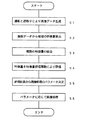
なお、本実施例の形態例の各手段は、ハードウェアやファームウェア、またはソフトウェアで構成することが可能である。このため、画像処理方法の各ステップ,画像処理装置の各手段,画像処理プログラムの各ルーチンの処理手順に沿った機能ブロック図としての図1を示す。 Note that each means of the embodiment of the present embodiment can be configured by hardware, firmware, or software. For this reason, FIG. 1 is shown as a functional block diagram in accordance with the processing procedure of each step of the image processing method, each means of the image processing apparatus, and each routine of the image processing program.
以下、本実施の形態例の構成および動作について、図1のブロック図、図2のフローチャート、および、その他の説明図を参照しつつ詳細に説明する。なお、図1における各手段は、画像形成装置の各手段を示すだけでなく、画像処理方法の各ステップ、画像処理プログラムの各ルーチンを示すものである。 Hereinafter, the configuration and operation of the present embodiment will be described in detail with reference to the block diagram of FIG. 1, the flowchart of FIG. 2, and other explanatory diagrams. Each unit in FIG. 1 represents not only each unit of the image forming apparatus but also each step of the image processing method and each routine of the image processing program.
〈全体構成および処理の流れ〉
1)全体構成:
放射線発生装置30、放射線画像読取器40、画像処理装置100が、図1に示されるように構成されている。
<Overall configuration and processing flow>
1) Overall configuration:
The radiation generating device 30, the radiation image reader 40, and the image processing device 100 are configured as shown in FIG.
また、画像処理装置100内部には、制御手段101、画像データ生成手段110、特徴量算出手段120、特徴量統合手段130、特徴量評価手段140、パラメータ決定手段150が、図1に示すように構成される。
Further, in the image processing apparatus 100, a
2)処理の流れ:
・制御手段101は放射線画像撮影・読み取り、および、画像処理のパラメータ決定に伴う各種処理についての制御を行う。
・放射線発生装置30からの放射線は被写体5を透過し、この被写体5を透過した放射線は放射線画像読取器40により読み取られる。
・放射線画像読取器40により読み取られた信号は、画像データ生成手段110で画像データに変換される(図2S1)。
・特徴量算出手段120は、放射線画像データの特徴量を算出する(図2S2)。
・特徴量統合手段130は、放射線画像データ特徴量を統合する(図2S3)。
・特徴量評価手段140は、算出あるいは統合された特徴量を特徴量評価関数により評価する(図2S4)。
・パラメータ決定手段150は、評価された前記特徴量の評価結果に基づいて、画像処理のパラメータ(画像処理条件)を決定する(図2S5)。
・画像処理手段160は、画像データ生成手段110からの画像データについて、パラメータ決定手段150で決定されたパラメータに従って画像処理を実行する(図2S6)。
2) Process flow:
The
The radiation from the radiation generator 30 passes through the subject 5, and the radiation that has passed through the subject 5 is read by the radiation image reader 40.
The signal read by the radiation image reader 40 is converted into image data by the image data generation unit 110 (S1 in FIG. 2).
The feature
The feature
The feature
The
The
〈各手段、各ステップの詳細内容〉
(1)各部の動作・制御:
制御手段101では、まず、撮影部位または撮影方向等の情報をユーザインターフェースなどから取得する。これらの情報は、ユーザが撮影部位等を特定することで行う。例えば、表示部とタッチパネルとを兼ね備えた当該画像処理装置のユーザインタフェース(図示せず)から、撮影部位が表示されたボタンを押すこと等により入力される。そのほか、磁気カード、バーコード、HIS(病院内情報システム:ネットワークによる情報管理)等を利用しても行われる。
<Details of each means and step>
(1) Operation and control of each part:
In the control means 101, first, information such as an imaging region or an imaging direction is acquired from a user interface or the like. Such information is performed by the user specifying an imaging region or the like. For example, it is input from a user interface (not shown) of the image processing apparatus having both a display unit and a touch panel by pressing a button displaying an imaging region. In addition, a magnetic card, bar code, HIS (hospital information system: network-based information management), etc. are used.
(2)放射線画像入力:
放射線発生器30は制御手段101によって制御されており、放射線発生器30から放射された放射線は、被写体5を通して放射線画像読取器40の前面に装着されている撮像パネルに照射される。そして、放射線画像読取器40では、被写体5を透過した放射線を検知して、画像信号として取得する。
(2) Radiation image input:
The radiation generator 30 is controlled by the control means 101, and the radiation emitted from the radiation generator 30 is applied to the imaging panel mounted on the front surface of the radiation image reader 40 through the subject 5. The radiation image reader 40 detects the radiation transmitted through the subject 5 and acquires it as an image signal.
具体的な構成例としては、輝尽性蛍光体プレートを用いたものとして、特開平11-142998号公報や特開2002-156716号公報に記載されたものがある。また、フラットパネルディテクタ(FPD)を入力装置として用いるものには、特開平6-342098号公報に記載された、検出したX線を直接電荷に変換し、画像信号として取得するものや、特開平9-90048号公報に記載された、検出したX線を一旦光に変換した後、その光を受光して電荷に変換する、間接方式のものがある。 Specific examples of the configuration include those described in JP-A-11-142998 and JP-A-2002-156716 as using a stimulable phosphor plate. For those using a flat panel detector (FPD) as an input device, those described in Japanese Patent Laid-Open No. 6-342098 that directly convert detected X-rays into charges and obtain them as image signals, There is an indirect system described in Japanese Patent Laid-Open No. 9-90048 in which detected X-rays are once converted into light and then received and converted into electric charges.
なお、放射線画像読取器40は、放射線画像を記録した銀塩フィルムにレーザ、蛍光灯等の光源からの光を照射し、この銀塩フィルムの透過光を光電変換して画像データを生成してもよい。また、放射線量子計数型検出器を用いて放射線エネルギーを直接電気信号に変換して画像データを生成する構成であってもよい。 The radiation image reader 40 irradiates the silver salt film on which the radiation image is recorded with light from a light source such as a laser or a fluorescent lamp, and photoelectrically converts the transmitted light of the silver salt film to generate image data. Also good. Moreover, the structure which converts radiation energy directly into an electrical signal using a radiation quantum counting type detector, and produces | generates image data may be sufficient.
被写体5の放射線画像を得る際には、放射線発生器30と放射線画像読取器40の撮像パネルの間に被写体5が位置するものとされて、放射線発生器30から放射された放射線が被写体5に照射されると共に、被写体5を透過した放射線が撮像パネルに入射される。 When obtaining a radiation image of the subject 5, the subject 5 is assumed to be positioned between the radiation generator 30 and the imaging panel of the radiation image reader 40, and the radiation emitted from the radiation generator 30 is applied to the subject 5. Irradiation and radiation transmitted through the subject 5 are incident on the imaging panel.
(3)関心領域設定:
ところで、放射線画像の撮影に際しては、例えば診断に必要とされない部分に放射線が照射されないようにするため、あるいは診断に必要とされない部分に放射線が照射されて、この部分で散乱された放射線が診断に必要とされる部分に入射されて分解能が低下することを防止するため、被写体5の一部や放射線発生器30に鉛板等の放射線非透過物質を設置して、被写体5に対する放射線の照射野を制限する照射野絞りが行われる。
(3) Region of interest setting:
By the way, when taking a radiographic image, for example, in order to prevent radiation from being applied to a part that is not required for diagnosis, or to a part that is not required for diagnosis, radiation scattered in this part is used for diagnosis. In order to prevent the resolution from being reduced by being incident on a required portion, a radiation non-transparent material such as a lead plate is installed in a part of the subject 5 or the radiation generator 30 so that the radiation field to the subject 5 is irradiated. Irradiation field restriction is performed to limit the above.
この照射野絞りが行われた場合、照射野内領域と照射野外領域の画像データを用いてレベルの変換処理やその後の階調処理を行うものとすると、照射野外領域の画像データによって、照射野内の診断に必要とされる部分の画像処理が適正に行われなくなってしまう。このため、画像データ生成手段110では、照射野内領域と照射野外領域を判別する照射野認識が行われる。 When this irradiation field stop is performed, if level conversion processing and subsequent gradation processing are performed using the image data of the irradiation field area and the irradiation field area, the image data in the irradiation field is determined by the image data of the irradiation field area. Image processing of a part required for diagnosis is not performed properly. For this reason, the image data generation means 110 performs irradiation field recognition for discriminating between the irradiation field area and the irradiation field area.
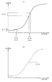
照射野認識では、例えば特開昭63−259538号で示される方法が用いられて、図3Aに示すように撮像面上の所定の位置Pから撮像面の端部側に向かう線分上の画像データを用いて例えば微分処理が行われる。この微分処理によって得られた微分信号Sdは、図3Bに示すように照射野エッジ部で信号レベルが大きくなるため、微分信号Sdの信号レベルを判別して1つの照射野エッジ候補点EP1が求められる。この照射野エッジ候補点を求める処理を、撮像面上の所定の位置を中心として放射状に行うことにより複数の照射野エッジ候補点EP1〜EPkが求められる。このようにして得られた複数の照射野エッジ候補点EP1〜EPkの隣接するエッジ候補点を直線あるいは曲線で結ぶことにより照射野エッジ部が求められる。 In the irradiation field recognition, for example, a method disclosed in Japanese Patent Laid-Open No. 63-259538 is used, and an image on a line segment from a predetermined position P on the imaging surface toward the end of the imaging surface as shown in FIG. 3A. For example, differential processing is performed using the data. As shown in FIG. 3B, the differential signal Sd obtained by this differentiation process has a signal level that is large at the irradiation field edge portion. Therefore, one signal field edge candidate point EP1 is obtained by determining the signal level of the differential signal Sd. It is done. A plurality of irradiation field edge candidate points EP1 to EPk are obtained by performing the process of obtaining the irradiation field edge candidate points radially about a predetermined position on the imaging surface. An irradiation field edge portion is obtained by connecting adjacent edge candidate points of the plurality of irradiation field edge candidate points EP1 to EPk obtained in this way with straight lines or curves.
また、特開平5−7579号で示される方法を用いることもできる。この方法では、撮像面を複数の小領域に分割したとき、照射野絞りによって放射線の照射が遮られた照射野外の小領域では、略一様に放射線の放射線量が小さくなり画像データの分散値が小さくなる。また、照射野内の小領域では、被写体によって放射線量が変調されることから照射野外に比べて分散値が高くなる。さらに、照射野エッジ部を含む小領域では最も放射線量が小さい部分と被写体によって変調された放射線量の部分が混在することから分散値は最も高くなる。このことから、分散値によって照射野エッジ部を含む小領域が判別される。 Moreover, the method shown by Unexamined-Japanese-Patent No. 5-7579 can also be used. In this method, when the imaging surface is divided into a plurality of small areas, the radiation dose of the radiation is reduced substantially uniformly in the small areas outside the irradiation field where radiation irradiation is blocked by the irradiation field stop. Becomes smaller. In addition, in a small region within the irradiation field, the radiation value is modulated by the subject, so that the dispersion value is higher than that outside the irradiation field. Further, in a small region including the irradiation field edge portion, the portion with the smallest radiation dose and the portion with the radiation dose modulated by the subject coexist, so the dispersion value is the highest. From this, the small area including the irradiation field edge portion is determined by the dispersion value.
また、特開平7−181609号で示される方法を用いることもできる。この方法では、画像データを所定の回転中心に関して回転移動させて、平行状態検出手段によって照射野の境界線が画像上に設定された直交座標の座標軸と平行となるまで回転を行うものとし、平行状態が検出されると、直線方程式算出手段によって回転角度と回転中心から境界線までの距離によって回転前の境界の直線方程式が算出される。その後、複数の境界線に囲まれる領域を直線方程式から決定することで、照射野の領域を判別することができる。また照射野エッジ部が曲線である場合には、境界点抽出手段で画像データに基づき例えば1つの境界点を抽出し、この境界点の周辺の境界候補点群から次の境界点を抽出する。以下同様に、境界点の周辺の境界候補点群から境界点を順次抽出することにより、照射野エッジ部が曲線であっても判別することができる。 Moreover, the method shown by Unexamined-Japanese-Patent No. 7-181609 can also be used. In this method, image data is rotated about a predetermined center of rotation, and rotation is performed until the boundary line of the irradiation field becomes parallel to the coordinate axis of the orthogonal coordinates set on the image by the parallel state detection means. When the state is detected, the linear equation of the boundary before rotation is calculated by the linear equation calculation means based on the rotation angle and the distance from the rotation center to the boundary line. Thereafter, by determining a region surrounded by a plurality of boundary lines from a linear equation, the region of the irradiation field can be determined. When the irradiation field edge portion is a curve, for example, one boundary point is extracted based on the image data by the boundary point extraction means, and the next boundary point is extracted from the boundary candidate point group around this boundary point. Similarly, by sequentially extracting boundary points from the boundary candidate point group around the boundary points, it is possible to determine whether the irradiation field edge portion is a curve.
照射野認識が行われると、放射線画像読取器からの画像データDTの分布を所望のレベルの分布に変換する際に、放射線画像読取器からの画像データDTのレベルの分布を決定するための領域(以下「関心領域」という)の設定を行う。 When the irradiation field recognition is performed, an area for determining the level distribution of the image data DT from the radiation image reader when the distribution of the image data DT from the radiation image reader is converted into a distribution at a desired level. (Hereinafter referred to as “region of interest”).
この関心領域の設定では、たとえば胸部正面画像では診断上重要な領域がすべて含まれるように肺野全体に設定される。この関心領域の設定は例えば図7のように画像内の1/3〜2/3の領域での水平方向の平均プロファイルを作成し、はじめに画像中央の最小値Pを決定する。次に画像の両端に向かって、最大値を検出する(図7中のA、B)。次にそれぞれの最大値から画像端に向かって、最大値と最小値間の所定の割合になる点を探すことで関心領域の左右端を決定することができる。この所定の割合については例えば経験的に4/5程度にすることで、適切に左右端を決定することができる。さらに得られた左右端の範囲での垂直方向の平均プロファイルを作成し、水平方向と同様な処理を行い、図中のX,Y,Qを検出することで上下端を決定できる。このほか診断上重要な部分は画像中央に撮影されることことを考慮し関心領域画像中央に設定する、頭部などのように診断上重要な部分が広範囲に渡る場合は照射野領域全体を関心領域に設定する方法などが考えられる。 In the setting of the region of interest, for example, the entire lung field is set so that all regions important for diagnosis are included in the chest front image. For the setting of the region of interest, for example, as shown in FIG. 7, an average profile in the horizontal direction is created in the region of 1/3 to 2/3 in the image, and the minimum value P at the center of the image is first determined. Next, the maximum value is detected toward both ends of the image (A and B in FIG. 7). Next, the left and right ends of the region of interest can be determined by searching for a point having a predetermined ratio between the maximum value and the minimum value from each maximum value toward the image end. By setting the predetermined ratio to about 4/5 empirically, the left and right ends can be determined appropriately. Furthermore, an average profile in the vertical direction in the range of the obtained left and right ends is created, processing similar to that in the horizontal direction is performed, and X, Y, and Q in the figure can be detected to determine upper and lower ends. In addition, consider the fact that a diagnostically important part is taken at the center of the image, and set it at the center of the region of interest image. If a part that is important for diagnosis such as the head covers a wide area, the entire irradiation field area is of interest. A method for setting the area may be considered.
(4)特徴量算出:
ここで、特徴量算出手段130は、放射線画像内の特徴量を算出する。この特徴量として、たとえば、画像に微分フィルタあるいはラプラシアンフィルタなどの高周波領域を抽出するフィルタ処理を行うことによって得られるエッジ成分の絶対値を画像のエッジ領域のコントラストとしてとることができる。
(4) Feature amount calculation:
Here, the feature
図4(a)は頚椎についてのオリジナルの画像、図4(b)は図4(a)の頚椎画像について抽出されたエッジを示した様子である。 FIG. 4A shows an original image of the cervical vertebra, and FIG. 4B shows an edge extracted from the cervical image of FIG. 4A.
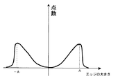
この場合、コントラストの大きさ、すなわちエッジ成分の絶対値の大きさにしたがって点数をつけ、点数がどの画素値にどのように分布しているかのヒストグラムを作成することで、コントラスト(エッジ)の大きさを各画素への重みとして用いることができる。ここで点数のつけ方については、たとえば絶対値がある経験的に定められた閾値A以下の場合は絶対値の値を点数とし、A以上の場合は0とすることで人体から構成されると予想されるエッジのみにエッジに応じた点数を与えることができる。この他、閾値Aを用いて、図8のような関数を用いて滑らかに変化させてもよい。 In this case, by assigning points according to the magnitude of the contrast, that is, the absolute value of the edge component, and creating a histogram of how the points are distributed to which pixel value, the magnitude of the contrast (edge) Can be used as a weight to each pixel. For example, if the absolute value is less than an empirically determined threshold A, the absolute value is scored, and if it is greater than A, the score is set to 0. Only the expected edge can be given a score corresponding to the edge. In addition, the threshold A may be used to smoothly change the function as shown in FIG.
また、たとえば、エッジ領域の抽出にはラプラシアンピラミッド法やウェーブレットなどの多重解像度法を用いることもできる。これらの多重解像度法を用いた高周波成分抽出については、たとえば特開平5−244508号公報や特開平6−274614号公報に詳しい記載がある。 Further, for example, a multi-resolution method such as a Laplacian pyramid method or a wavelet can be used for extracting the edge region. High frequency component extraction using these multi-resolution methods is described in detail in, for example, Japanese Patent Application Laid-Open Nos. 5-244508 and 6-274614.
上記コントラストにより算出された重み付けの値を画像内のすべてのエッジ領域について総和した値が特徴量に相当する。このほか、特徴量としては、たとえば、画像平均濃度や、画像内の画素信号値の分散値や中央度(どれだけ中央(画像中心)に近いかの度合い)、なども考えられ、このほか
(a) 領域内の画素信号値の最大値もしくは最小値のいずれか、
(b) 領域内の画素信号値のメジアン、
(c) 領域内の画素信号値の最頻値(モード)、
(d) 領域内の画素信号値の分散もしくは標準偏差のいずれか一方、
(e) 隣接あるいは所定間隔の画素の画素値差分、
なども考えられる。
A value obtained by summing the weighting values calculated based on the contrast for all edge regions in the image corresponds to the feature amount. In addition, as the feature amount, for example, the average density of the image, the dispersion value of the pixel signal value in the image, and the median degree (how close to the center (image center)) can be considered.
(a) Either the maximum or minimum pixel signal value in the area,
(b) the median of the pixel signal values in the region,
(c) Mode value (mode) of pixel signal values in the area,
(d) Either the variance or standard deviation of pixel signal values in the area,
(e) Pixel value difference between adjacent or predetermined interval pixels,
Etc. are also conceivable.
(5)特徴量統合:
ここで特徴量統合手段130では、特徴量算出手段120で算出された複数の特徴量のなかで、より診断に重要な組み合わせが重要視されるように結合される。これにより、診断に必要な領域を重視した処理が可能となる。
(5) Feature amount integration:
Here, in the feature
より具体的には例えば、たとえば、(x,y)を画素、P(x,y)を画素値とし、画像エッジ部のコントラストW_1(x,y)、画像中央度W_2(x,y)とした場合、結合重みをA(P,W_1,W_2)とすれば特徴量Cを、
C=ΣA(P,W_1,W_2)P(x,y)+A(P,W_1,W_2)W_1(x,y)+A(P,W_1,W_2)W_2(x,y)
で与えることができる。ここでΣはエッジ領域すべてでの総和を表すものとする。AをたとえばP1<P<P2,W1<W_1<W2,W3>W_2を満たす領域でのみ2を取り、その他の領域では1をとるようにすれば、信号値が人体領域と推定されるP1〜P2の範囲かつ、照射野のエッジなどを除いた人体により形成されるエッジの範囲W1〜W2にエッジがあり、ある一定値W3よりが画像中央にある画素にのみ、2倍の得点を配点することができる。これらのP1,P2,W1〜W3は判別分析法などを使用し、経験的に求められる値である。この結合には上記のような方法のほかファジイ積分を用いた手法も考えられる。
More specifically, for example, (x, y) is a pixel, P (x, y) is a pixel value, contrast W_1 (x, y) of the image edge portion, image centrality W_2 (x, y) and If the connection weight is A (P, W_1, W_2), the feature value C is
C = ΣA (P, W_1, W_2) P (x, y) + A (P, W_1, W_2) W_1 (x, y) + A (P, W_1, W_2) W_2 (x, y)
Can be given in Here, Σ represents the total sum in all edge regions. For example, if A is set to 2 only in the region satisfying P1 <P <P2, W1 <W_1 <W2, W3> W_2 and 1 in other regions, the signal value is estimated to be a human body region P1. The range of P2 and the edge range W1 to W2 formed by the human body excluding the edge of the irradiation field has an edge, and a score of twice is assigned only to the pixel in the center of the image with a certain value W3. be able to. These P1, P2, W1 to W3 are values obtained empirically using a discriminant analysis method or the like. In addition to the above method, a method using fuzzy integration can be considered for this connection.
(6)特徴量評価:
ここで、特徴量評価手段140は、特徴量算出手段120で算出され、特徴量統合手段130で統合された特徴量を、特徴量評価関数により評価する。
(6) Feature amount evaluation:
Here, the feature
以下、ルックアップテーブルの使用効率を最大にする階調処理の例について説明する。この特徴量評価関数Eとしてのは、基本式として、
E=Σf(Δx′/Δx)W(x)、
と示すことができる。
An example of gradation processing that maximizes the use efficiency of the lookup table will be described below. The feature quantity evaluation function E is as a basic expression:
E = Σf (Δx ′ / Δx) W (x),
Can be shown.
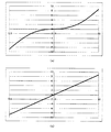
ここで、fは特徴量評価関数、Δxはxにおける画素値の微小変化であり、具体的にはある一定値δをxを中心に可算、減算したもので区間(x−δ,x+δ)の長さを表す。またΔx'は階調特性を決定するルックアップテーブルであるLUT通過後のXの値x'の微小変化で具体的にはLUTによるXの変換後の値をLUT(x)で表せば区間(LUT(x−δ),LUT(x+δ))の長さを表す。また、W(x)はxの重みである。図5(a)では、x1におけるΔx1とΔx1′、x2におけるΔx2とΔx2′、の例を示している。このような特徴量評価関数fを、エッジと認められる全ての点で行ってΣを算出する。 Here, f is a feature value evaluation function, and Δx is a minute change in the pixel value at x. Specifically, a certain value δ is counted and subtracted around x, and is in the section (x−δ, x + δ). Represents length. Δx ′ is a slight change in the value x ′ of X after passing through the LUT, which is a look-up table for determining gradation characteristics. Specifically, if the value after conversion of X by the LUT is expressed by LUT (x), an interval ( LUT (x−δ), LUT (x + δ)) is represented. W (x) is a weight of x. FIG. 5A shows an example of Δx1 and Δx1 ′ at x1 and Δx2 and Δx2 ′ at x2. Such a feature quantity evaluation function f is performed at all points recognized as edges to calculate Σ.
なお、特徴量評価関数fとしては、
Δx′/Δx=10では10、
Δx′/Δx=5では5、
Δx′/Δx=1では0、
Δx′/Δx=1/5では−5、
Δx′/Δx=1/10では−10、
などとすることができる。このような特徴量評価関数fとしては、たとえば、図6(a)あるいは図6(b)のような特性になる。
As the feature quantity evaluation function f,
10 for Δx ′ / Δx = 10,
5 for Δx ′ / Δx = 5,
0 when Δx ′ / Δx = 1.
If Δx ′ / Δx = 1/5, −5,
When Δx ′ / Δx = 1/10, −10,
And so on. Such a feature quantity evaluation function f has characteristics as shown in FIG. 6A or FIG. 6B, for example.
また、たとえば、階調特性を決定するルックアップテーブル(図5参照)のシフト値S、グラデーション値Gを変数として、あるSG値のルックアップテーブルで変換した後の画像からエッジ検出処理を行い、その比を取る方法が考えられる。このSG値は具体的には基本となるLUTに対して、LUT(Ax−B)により画像を変換した場合、グラデーション値GをA、シフト値SをBと定義する。 Also, for example, edge detection processing is performed from an image after conversion using a lookup table of a certain SG value using the shift value S and gradation value G of the lookup table (see FIG. 5) for determining gradation characteristics as variables, A method of taking the ratio can be considered. Specifically, the SG value is defined such that the gradation value G is A and the shift value S is B when an image is converted by the LUT (Ax-B) with respect to the basic LUT.
すなわち、評価関数をEとすると、
E(S,G)=EDGE(S,G)/ORG_E(S,G)
とすればよい。
That is, if the evaluation function is E,
E (S, G) = EDGE (S, G) / ORG_E (S, G)
And it is sufficient.
ここで、EDGE(S,G)はルックアップテーブル変換後の画像の平均コントラスト、ORG_E(S,G)はオリジナルの画像の平均コントラストである。このコントラストはたとえば、直接画像から求めるものではなく、入力は常に一定値とし、あるしきい値を超えるエッジ点でのルックアップテーブル通過後、この一致値の振幅がどう変わったかを評価するものでも良い。すなわち、以下のようである。
E(S,G)=Σ{(LUT(S,G,x+A)−LUT(S,G,x−A))/(2*A)*W(x)}…(A)、で与えられる。ここでAは画素値xにおける微小区間を表す定数で例えば12ビット階調の画像でに対して5などの非常に小さい値が選ばれる。またW(x)は各画素に対する重要度をあらわした重みであり、LUT(S,G,x)は与えられたSG値でのルックアップテーブルで画像内の点xを変換した際の出力値を示し、Σは検出されたエッジ点の全ての領域での和を表す。ここでは、コントラストの評価を例にしたが、同様に変換後の画像と変換前の画像の分散の比を評価関数とすることもできるし、同様に変換後の画像の平均濃度を評価関数とすることもできる。
Here, EDGE (S, G) is the average contrast of the image after the lookup table conversion, and ORG_E (S, G) is the average contrast of the original image. This contrast is not obtained directly from the image, for example. The input is always a constant value, and it is possible to evaluate how the amplitude of the coincidence value has changed after passing the lookup table at an edge point exceeding a certain threshold value. good. That is, it is as follows.
E (S, G) = Σ {(LUT (S, G, x + A) −LUT (S, G, x−A)) / (2 * A) * W (x)} (A) . Here, A is a constant representing a minute interval in the pixel value x, and a very small value such as 5 is selected for a 12-bit gradation image, for example. W (x) is a weight representing the importance for each pixel, and LUT (S, G, x) is an output value when a point x in the image is converted by a lookup table with a given SG value. Σ represents the sum of all detected edge points in all regions. Here, the evaluation of contrast is taken as an example. Similarly, the ratio of the variance between the converted image and the image before conversion can be used as an evaluation function, and the average density of the image after conversion is also used as the evaluation function. You can also
たとえば、分散の比の場合、
E(S)=Σ{VAR(S)/ORG_V(S)}
となる。ここで、VAR(S)は変換後の平均分散、ORG_V(S)はオリジナル画像の分散とし、Σは画像のある領域内の点における和を表す。
For example, for the ratio of variance:
E (S) = Σ {VAR (S) / ORG_V (S)}
It becomes. Here, VAR (S) is the average variance after conversion, ORG_V (S) is the variance of the original image, and Σ represents the sum at points in a certain area of the image.
さらに、たとえば、平均の比の場合、
E(S)=AVE(S,G)−A
となる。ここで、AVE(S,G)は変換後の平均信号値、Aは定数である。
Furthermore, for example, in the case of an average ratio:
E (S) = AVE (S, G) -A
It becomes. Here, AVE (S, G) is the average signal value after conversion, and A is a constant.
(7)パラメータ決定:
ここで、パラメータ決定手段150は、特徴量評価手段140で特徴量評価関数により評価された結果であるE(S,G)が最大あるいは最小になるようなS値、G値を求める。
(7) Parameter determination:
Here, the
このようにすることで、たとえば、特徴量をコントラストとすれば、E(S,G)が最大になるようにすることで、変換後の画像の全体としての重要領域のコントラスト増幅率を最大になるようにすることができる。 In this way, for example, if the feature amount is contrast, E (S, G) is maximized, so that the contrast amplification factor of the important region as a whole of the converted image is maximized. Can be.
また、たとえば、特徴量を分散とすれば、評価関数が最小になるようにすることで、ある領域内の画像のばらつきが最も小さくなるようにS値を決定できる。 Further, for example, if the feature amount is variance, the S value can be determined so that the variation of the image within a certain region is minimized by minimizing the evaluation function.
また、たとえば、 特徴量が平均値の場合には、評価関数が最小になるようにすることで、ある領域内の画像画像平均値が特定の定数Aと等しくなるようにできる。 Further, for example, when the feature amount is an average value, the average image value in a certain region can be made equal to a specific constant A by minimizing the evaluation function.
さらに、これらの関数を組み合わせることで、評価手段140において別の評価関数を作成することも可能である。 Furthermore, it is possible to create another evaluation function in the evaluation means 140 by combining these functions.
また、以上の特徴量評価結果を単独に用いるのではなく、複数を組み合わせて、変換後の画像の全体として重要領域のコントラスト増幅率、平均値を所望の状態にすることもできる。具体的にはコントラスト増幅率の評価関数をEC(S,G)、平均値をEA(S)とすれば、
E(S,G)=EA(S)*EC(S,G)、
を評価関数とすることで、コントラストが大きく濃度が所定値Aに近いほど高い得点を算出することができ、したがって、平均画素値がAに近くコントラストの増幅率が高いLUTを決定することができる。
In addition, the above feature amount evaluation results are not used alone, but a plurality of them can be combined to bring the contrast amplification factor and average value of the important region into a desired state as a whole of the converted image. Specifically, if the evaluation function of the contrast amplification factor is EC (S, G) and the average value is EA (S),
E (S, G) = EA (S) * EC (S, G),
By using as an evaluation function, a higher score can be calculated as the contrast is larger and the density is closer to the predetermined value A. Therefore, an LUT having an average pixel value close to A and a high contrast amplification factor can be determined. .
なお、以上の説明で、パラメータライズされた変換方法は、階調処理のためのルックアップテーブルによる画素値変換の他に、周波数強調処理やイコライゼーション処理などが考えられる。これらの処理については特開2001−120524号公報、特開昭62−62373号公報、特開平9−44645号公報や特許第2663189号公報などに詳しい記載がある。評価関数として、処理前と処理後の分散の比やエッジサイズの変化率などをとることで、これらの処理に対して適切なパラメータを決定することが可能となる。例えば、周波数強調処理は強調係数β、イコライゼーション処理における信号補正関数の傾きの絶対値Kなどによって処理が決定されるが、周波数強調処理の評価関数として
EF(β)=[EDGE(β)/EDGE_ORG(β)]/Σ[VAR(β)/ORG_V(β)]-A、
選べば、エッジの増幅度と画素分散値の比が特定値Aにつねに近くなるように強調度を決定することができ、エッジの強調と画像のざらつきをコントロールすることが可能となる。ここでEDGE(β)はオリジナル画像の平均コントラスト、EDGE_ORG(β)は周波数強調処理後の平均コントラスト、VAR(β)は周波数強調後の画像平均分散値の ORG_V(β)はオリジナル画像の平均信号値、Aは経験的に定まる定数である。
In the above description, the parameterized conversion method includes frequency enhancement processing and equalization processing in addition to pixel value conversion using a lookup table for gradation processing. 2001-120524 JP-for these processes, JP 62-62373 and JP, etc. in detailed description JP 9-44645 Patent Publication and Patent No. 2663189 Publication. By taking the ratio of variance before processing and after processing, the rate of change in edge size, and the like as evaluation functions, it is possible to determine appropriate parameters for these processing. For example, the frequency enhancement processing is determined by the enhancement coefficient β, the absolute value K of the slope of the signal correction function in the equalization processing, and the like. EF (β) = [EDGE (β) / EDGE_ORG (β)] / Σ [VAR (β) / ORG_V (β)]-A,
If selected, the degree of enhancement can be determined so that the ratio between the amplification degree of the edge and the pixel dispersion value is always close to the specific value A, and the enhancement of the edge and the roughness of the image can be controlled. Where EDGE (β) is the average contrast of the original image, EDGE_ORG (β) is the average contrast after frequency enhancement processing, VAR (β) is the average dispersion value of the image after frequency enhancement ORG_V (β) is the average signal of the original image The value A is a constant determined empirically.
さらにイコラゼーション処理の場合、D_ORG(K)をオリジナル画像のダイナミックレンジ(画像内の最大信号値-最小信号値)、D(K)をイコライゼーション処理後のダイナミックレンジ、L(K,x)を画素xのイコライゼーション処理後の値をLUTにより変換した場合の値としたとき、
EF(K)=Σ{L(K,x+A)-L(K,x−A)/2*A}/α{D(K)/D_ORG(K)}、
で与える。ここでΣはたとえば検出されたエッジ領域すべてにおける総和を表すものとする。このようにすることで画像全体のコントラストを考慮し、かつ診断上重要な領域のイコライゼーション処理後のコントラスト増幅率が適切になるように補正の強度を決定することができる。上式のαは適切な値が算出されるようにするための補正係数で経験的に求められる値である。
Furthermore, in the case of equalization processing, D_ORG (K) is the dynamic range of the original image (maximum signal value-minimum signal value in the image), D (K) is the dynamic range after equalization processing, and L (K, x) is the pixel. When the value after equalization processing of x is the value when converted by LUT,
EF (K) = Σ {L (K, x + A) −L (K, x−A) / 2 * A} / α {D (K) / D_ORG (K)},
Give in. Here, Σ represents, for example, the total sum in all detected edge regions. In this way, the intensity of correction can be determined so that the contrast of the entire image is taken into account and the contrast amplification factor after equalization processing in an area important for diagnosis is appropriate. Α in the above equation is a value empirically obtained as a correction coefficient for calculating an appropriate value.
(8)画像処理:
画像処理手段160は、画像データ生成手段110からの画像データについて、以上の説明のようにしてパラメータ決定手段150で決定されたパラメータにしたがって、画像処理を実行する。
(8) Image processing:
The
具体的には例えば階調処理においては、上記の評価関数(A)により決定されたSG値とLUTを使用して、画像データの各画素XをLUT(Gx−A)によって変換する。このようにすることで、処理済み画像は与えられた評価関数、すなわち上記例では変換後の重要画素のコントラスト増大率が最大になるように変換された画像となる。また、周波数強調処理やイコライゼーション処理においても同様に上記のような評価関数により決定した強調係数あるいは補正係数により、処理が行われる。この処理済み画像データは、図示されない画像表示手段、各種外部機器、画像出力装置などに供給される。 Specifically, for example, in gradation processing, each pixel X of image data is converted by LUT (Gx-A) using the SG value and LUT determined by the evaluation function (A). In this way, the processed image becomes a given evaluation function, that is, an image converted so that the contrast increase rate of the important pixel after conversion is maximized in the above example. Similarly, the frequency enhancement process and the equalization process are performed using the enhancement coefficient or the correction coefficient determined by the evaluation function as described above. The processed image data is supplied to image display means, various external devices, an image output device, etc. (not shown).
以上のように、放射線画像毎の特徴量に基づいて評価して決定したパラメータにより画像処理を実行するので、例えば、各信号値に対して特徴量に基づいて、重要度に応じた重み付けをして、各画素の階調処理用LUTにより変換した際の信号の増幅率を算出し、増幅率と重みを掛け合わせた値のすべての画素での総和が最大になるようなLUTを決定することで適切な画像処理が実行できる。ここで特徴量に基づいた重要度とは、たとえば一般に診断上重要なポイントは画像中央に位置することが多く、さらにエッジ成分をもつことなどから、特徴量として画像中心との距離を測る画像中央度と微分フィルタなどを用いて検出した各画素におけるエッジ強度を使用し、それらの値に基づいて決定される量である。また、増幅率としてはたとえば各画素値におけるLUTの傾きやそれに相当する量を考えることができる。 As described above, since image processing is executed with parameters determined by evaluation based on the feature amount for each radiographic image, for example, each signal value is weighted according to the importance based on the feature amount. Then, the amplification factor of the signal when converted by the gradation processing LUT of each pixel is calculated, and the LUT is determined such that the sum of the values obtained by multiplying the amplification factor and the weight becomes the maximum for all the pixels. Can execute appropriate image processing. Here, the importance based on the feature amount is, for example, that a point that is generally important for diagnosis is generally located at the center of the image and has an edge component. This is an amount determined based on the values using the edge intensity at each pixel detected using the degree and the differential filter. Further, as the amplification factor, for example, the slope of the LUT in each pixel value or an amount corresponding thereto can be considered.
この結果、画像処理条件決定の失敗により診断が困難となる状況の発生は防止され、画像データ毎に適切なパラメータが決定されるようになるので、いかなる場合であっても適切な条件あるいは適切に近い条件で画像処理することが可能になる。 As a result, it is possible to prevent the occurrence of a situation in which diagnosis is difficult due to failure in determining image processing conditions, and to determine appropriate parameters for each image data. Image processing can be performed under close conditions.
5 被写体
30 放射線発生装置
40 放射線画像読取器
100 画像処理装置
101 制御手段
110 画像データ生成手段
120 特徴量算出手段
130 特徴量統合手段
140 特徴量評価手段
150 パラメータ決定手段
160 画像処理手段
DESCRIPTION OF SYMBOLS 5 Subject 30 Radiation generation apparatus 40 Radiation image reader 100
Claims (3)
前記放射線画像のエッジ領域の各画素について、信号値に対応する前記ルックアップテーブルの傾きに基づく値をそれぞれ算出し、その総和が最大になるように、前記ルックアップテーブルのパラメータを決定するパラメータ決定ステップと、
前記パラメータ決定ステップで決定された前記パラメータで定義される前記ルックアップテーブルにより階調処理を実行する画像処理ステップと、
を有することを特徴とする画像処理方法。 An image processing method for performing gradation processing on a radiographic image having a signal value corresponding to an irradiation dose of radiation transmitted through a subject by converting the signal value using a lookup table in order to obtain an image suitable for diagnosis. ,
For each pixel in the edge region of the radiographic image, a value based on the slope of the lookup table corresponding to the signal value calculated respectively, so that the sum of that is maximized, the parameters to determine parameters of the look-up table A decision step;
An image processing step of performing gradation processing by the lookup table defined by the parameters determined in the parameter determination step;
An image processing method comprising:
前記放射線画像のエッジ領域の各画素について、信号値に対応する前記ルックアップテーブルの傾きに基づく値をそれぞれ算出し、その総和が最大になるように、前記ルックアップテーブルのパラメータを決定するパラメータ決定手段と、
前記パラメータ決定手段で決定された前記パラメータで定義される前記ルックアップテーブルにより階調処理を実行する画像処理手段と、
を有することを特徴とする画像処理装置。 An image processing apparatus that performs gradation processing by converting a signal value using a lookup table to obtain an image suitable for diagnosis with respect to a radiation image having a signal value corresponding to an irradiation dose of radiation transmitted through a subject. ,
For each pixel in the edge region of the radiographic image, a value based on the slope of the lookup table corresponding to the signal value calculated respectively, so that the sum of that is maximized, the parameters to determine parameters of the look-up table A determination means;
Image processing means for performing gradation processing by the lookup table defined by the parameters determined by the parameter determination means;
An image processing apparatus comprising:
ことを特徴とする画像処理プログラム。 Making a computer function as each means of the image processing apparatus according to claim 2;
An image processing program characterized by that.
Priority Applications (3)
| Application Number | Priority Date | Filing Date | Title |
|---|---|---|---|
| JP2003340417A JP4980552B2 (en) | 2003-09-30 | 2003-09-30 | Image processing method, image processing apparatus, and image processing program |
| EP04104576.6A EP1521209B1 (en) | 2003-09-30 | 2004-09-21 | Radiation image enhancement |
| US10/949,377 US20050069187A1 (en) | 2003-09-30 | 2004-09-27 | Image processing method, image processing apparatus and image processing program |
Applications Claiming Priority (1)
| Application Number | Priority Date | Filing Date | Title |
|---|---|---|---|
| JP2003340417A JP4980552B2 (en) | 2003-09-30 | 2003-09-30 | Image processing method, image processing apparatus, and image processing program |
Publications (3)
| Publication Number | Publication Date |
|---|---|
| JP2005109867A JP2005109867A (en) | 2005-04-21 |
| JP2005109867A5 JP2005109867A5 (en) | 2006-11-02 |
| JP4980552B2 true JP4980552B2 (en) | 2012-07-18 |
Family
ID=34309043
Family Applications (1)
| Application Number | Title | Priority Date | Filing Date |
|---|---|---|---|
| JP2003340417A Expired - Fee Related JP4980552B2 (en) | 2003-09-30 | 2003-09-30 | Image processing method, image processing apparatus, and image processing program |
Country Status (3)
| Country | Link |
|---|---|
| US (1) | US20050069187A1 (en) |
| EP (1) | EP1521209B1 (en) |
| JP (1) | JP4980552B2 (en) |
Families Citing this family (11)
| Publication number | Priority date | Publication date | Assignee | Title |
|---|---|---|---|---|
| EP1672551A3 (en) * | 1998-04-07 | 2006-08-30 | Canon Kabushiki Kaisha | Image processing method, apparatus, and storage medium for recognition of irradiation area |
| JP2005210384A (en) * | 2004-01-22 | 2005-08-04 | Konica Minolta Medical & Graphic Inc | Image processing method, image processor, and image processing program |
| US8036443B2 (en) | 2005-05-31 | 2011-10-11 | Konica Minolta Medical & Graphic, Inc. | Image processing method and image processor |
| JP4999163B2 (en) * | 2006-04-17 | 2012-08-15 | 富士フイルム株式会社 | Image processing method, apparatus, and program |
| JP4785133B2 (en) * | 2006-05-08 | 2011-10-05 | 株式会社日立メディコ | Image processing device |
| US7801344B2 (en) * | 2006-12-01 | 2010-09-21 | Carestream Health, Inc. | Edge boundary definition for radiographic detector |
| US8428387B2 (en) | 2007-03-06 | 2013-04-23 | Shimadzu Corporation | Edge evaluation method, edge detection method, image correction method, and image processing system |
| JP5022979B2 (en) * | 2007-07-12 | 2012-09-12 | 株式会社リコー | Image processing apparatus, image processing method, and program |
| JP5665393B2 (en) * | 2010-07-05 | 2015-02-04 | キヤノン株式会社 | Image processing apparatus, image processing method, and program |
| CN109800614B (en) * | 2018-12-19 | 2022-03-29 | 新大陆数字技术股份有限公司 | DPM code image contrast enhancement method and device |
| CN117455916B (en) * | 2023-12-25 | 2024-03-15 | 山东太阳耐磨件有限公司 | Visual detection method for surface defects of steel plate |
Family Cites Families (19)
| Publication number | Priority date | Publication date | Assignee | Title |
|---|---|---|---|---|
| US2663189A (en) * | 1951-07-11 | 1953-12-22 | Begwaco Meters Ltd | Dry gas meter |
| JPH06274614A (en) * | 1993-03-18 | 1994-09-30 | Fuji Photo Film Co Ltd | Image processing method |
| US5471987A (en) * | 1993-03-30 | 1995-12-05 | Konica Corporation | Method of compressing a dynamic range for a radiation image |
| JPH08186714A (en) * | 1994-12-27 | 1996-07-16 | Texas Instr Inc <Ti> | Noise removal of picture data and its device |
| JPH0944645A (en) * | 1995-07-27 | 1997-02-14 | Fuji Photo Film Co Ltd | Image processing method and device therefor |
| JP3808123B2 (en) * | 1995-10-11 | 2006-08-09 | 富士写真フイルム株式会社 | How to detect abnormal shadows |
| JPH1166280A (en) * | 1997-08-25 | 1999-03-09 | Shimadzu Corp | Medical image processor |
| JP2000079110A (en) * | 1998-07-07 | 2000-03-21 | Konica Corp | Picture processor |
| JP2000157518A (en) * | 1998-11-25 | 2000-06-13 | Konica Corp | Radiation image processor |
| WO2000036884A2 (en) * | 1998-12-17 | 2000-06-22 | Koninklijke Philips Electronics N.V. | X-ray examination apparatus including a control loop for adjusting the x-ray flux |
| JP2001029335A (en) * | 1999-07-22 | 2001-02-06 | Konica Corp | Radiation image processor |
| JP3736219B2 (en) * | 1999-08-13 | 2006-01-18 | コニカミノルタビジネステクノロジーズ株式会社 | Image processing apparatus and method |
| JP2001086409A (en) * | 1999-09-13 | 2001-03-30 | Konica Corp | Device and method for image processing |
| US6898327B1 (en) * | 2000-03-23 | 2005-05-24 | International Business Machines Corporation | Anti-flicker system for multi-plane graphics |
| US6633684B1 (en) * | 2000-07-07 | 2003-10-14 | Athentech Technologies Corp. | Distortion-free image contrast enhancement |
| JP2002074325A (en) * | 2000-08-31 | 2002-03-15 | Fuji Photo Film Co Ltd | Method and detector for detecting abnormal shadow candidate |
| EP1526480A1 (en) * | 2000-10-17 | 2005-04-27 | Fuji Photo Film Co., Ltd | Apparatus for suppressing noise by adapting filter characteristics to input image signal based on characteristics of input image signal |
| JP2002183727A (en) * | 2000-12-19 | 2002-06-28 | Konica Corp | Image processing device |
| JP2002183726A (en) * | 2000-12-19 | 2002-06-28 | Konica Corp | Image processing device |
-
2003
- 2003-09-30 JP JP2003340417A patent/JP4980552B2/en not_active Expired - Fee Related
-
2004
- 2004-09-21 EP EP04104576.6A patent/EP1521209B1/en not_active Expired - Fee Related
- 2004-09-27 US US10/949,377 patent/US20050069187A1/en not_active Abandoned
Also Published As
| Publication number | Publication date |
|---|---|
| JP2005109867A (en) | 2005-04-21 |
| EP1521209A2 (en) | 2005-04-06 |
| US20050069187A1 (en) | 2005-03-31 |
| EP1521209A3 (en) | 2011-02-23 |
| EP1521209B1 (en) | 2018-02-28 |
Similar Documents
| Publication | Publication Date | Title |
|---|---|---|
| JP4844560B2 (en) | Image processing method and image processing apparatus | |
| JP4980552B2 (en) | Image processing method, image processing apparatus, and image processing program | |
| JP3785817B2 (en) | Radiographic image processing device | |
| JP4129598B2 (en) | Image processing apparatus and image processing method | |
| US20050161617A1 (en) | Image processing method, apparatus, and program | |
| JP4608927B2 (en) | Image processing method, image processing apparatus, and image processing program | |
| EP2821011A1 (en) | Periodic pattern detection device and method | |
| JP2001238868A (en) | Method of image processing and its apparatus | |
| JP2000079110A (en) | Picture processor | |
| JP3814864B2 (en) | Radiographic image processing condition determining apparatus, image processing apparatus, radiographic image processing condition determining method, and image processing method | |
| JP4765391B2 (en) | Image processing method, image processing apparatus, and image processing program | |
| JP2001212118A (en) | Radiation image processing method and apparatus | |
| JP3800892B2 (en) | Radiation image processing device | |
| US20090208087A1 (en) | Radiographic image correction method, apparatus and recording-medium stored therein program | |
| JP3709759B2 (en) | Image processing method and image processing apparatus | |
| JP4650114B2 (en) | Image processing method, image processing apparatus, and image processing program | |
| JP3765320B2 (en) | Image processing condition determination apparatus and image processing apparatus for radiation image | |
| JP3731400B2 (en) | Image processing method and image processing apparatus | |
| JP2006333899A (en) | Method, apparatus and program for image processing | |
| JP2929030B2 (en) | Digital radiographic image position determination device | |
| JP2000157518A (en) | Radiation image processor | |
| JP3223428B2 (en) | Chest radiographic imaging position determination device | |
| JP4258092B2 (en) | Image processing apparatus and image processing method | |
| JP2001245140A (en) | Image processing apparatus and image processing method | |
| JPS62104264A (en) | Method for recognizing irradiation field |
Legal Events
| Date | Code | Title | Description |
|---|---|---|---|
| A521 | Request for written amendment filed |
Free format text: JAPANESE INTERMEDIATE CODE: A523 Effective date: 20060915 |
|
| A621 | Written request for application examination |
Free format text: JAPANESE INTERMEDIATE CODE: A621 Effective date: 20060915 |
|
| A977 | Report on retrieval |
Free format text: JAPANESE INTERMEDIATE CODE: A971007 Effective date: 20091105 |
|
| A131 | Notification of reasons for refusal |
Free format text: JAPANESE INTERMEDIATE CODE: A131 Effective date: 20091124 |
|
| A521 | Request for written amendment filed |
Free format text: JAPANESE INTERMEDIATE CODE: A523 Effective date: 20100125 |
|
| A02 | Decision of refusal |
Free format text: JAPANESE INTERMEDIATE CODE: A02 Effective date: 20100803 |
|
| A521 | Request for written amendment filed |
Free format text: JAPANESE INTERMEDIATE CODE: A523 Effective date: 20101104 |
|
| A911 | Transfer to examiner for re-examination before appeal (zenchi) |
Free format text: JAPANESE INTERMEDIATE CODE: A911 Effective date: 20101111 |
|
| A912 | Re-examination (zenchi) completed and case transferred to appeal board |
Free format text: JAPANESE INTERMEDIATE CODE: A912 Effective date: 20110225 |
|
| A521 | Request for written amendment filed |
Free format text: JAPANESE INTERMEDIATE CODE: A523 Effective date: 20111202 |
|
| A521 | Request for written amendment filed |
Free format text: JAPANESE INTERMEDIATE CODE: A523 Effective date: 20120323 |
|
| A01 | Written decision to grant a patent or to grant a registration (utility model) |
Free format text: JAPANESE INTERMEDIATE CODE: A01 |
|
| A61 | First payment of annual fees (during grant procedure) |
Free format text: JAPANESE INTERMEDIATE CODE: A61 Effective date: 20120419 |
|
| FPAY | Renewal fee payment (event date is renewal date of database) |
Free format text: PAYMENT UNTIL: 20150427 Year of fee payment: 3 |
|
| R150 | Certificate of patent or registration of utility model |
Free format text: JAPANESE INTERMEDIATE CODE: R150 |
|
| S111 | Request for change of ownership or part of ownership |
Free format text: JAPANESE INTERMEDIATE CODE: R313111 |
|
| R350 | Written notification of registration of transfer |
Free format text: JAPANESE INTERMEDIATE CODE: R350 |
|
| LAPS | Cancellation because of no payment of annual fees |