JP4971659B2 - GAME DEVICE, GAME DEVICE CONTROL METHOD, AND PROGRAM - Google Patents
GAME DEVICE, GAME DEVICE CONTROL METHOD, AND PROGRAM Download PDFInfo
- Publication number
- JP4971659B2 JP4971659B2 JP2006091966A JP2006091966A JP4971659B2 JP 4971659 B2 JP4971659 B2 JP 4971659B2 JP 2006091966 A JP2006091966 A JP 2006091966A JP 2006091966 A JP2006091966 A JP 2006091966A JP 4971659 B2 JP4971659 B2 JP 4971659B2
- Authority
- JP
- Japan
- Prior art keywords
- desired trajectory
- game
- user
- trajectory data
- determined
- Prior art date
- Legal status (The legal status is an assumption and is not a legal conclusion. Google has not performed a legal analysis and makes no representation as to the accuracy of the status listed.)
- Active
Links
- 238000000034 method Methods 0.000 title claims description 23
- PWPJGUXAGUPAHP-UHFFFAOYSA-N lufenuron Chemical compound C1=C(Cl)C(OC(F)(F)C(C(F)(F)F)F)=CC(Cl)=C1NC(=O)NC(=O)C1=C(F)C=CC=C1F PWPJGUXAGUPAHP-UHFFFAOYSA-N 0.000 title 1
- 238000005452 bending Methods 0.000 claims description 10
- 230000006870 function Effects 0.000 description 29
- 239000004973 liquid crystal related substance Substances 0.000 description 12
- 238000004891 communication Methods 0.000 description 11
- 238000003825 pressing Methods 0.000 description 6
- 238000010586 diagram Methods 0.000 description 5
- 230000014509 gene expression Effects 0.000 description 5
- 238000012790 confirmation Methods 0.000 description 4
- 238000004364 calculation method Methods 0.000 description 3
- 230000000694 effects Effects 0.000 description 3
- 230000004044 response Effects 0.000 description 3
- 230000001133 acceleration Effects 0.000 description 1
Images


Classifications
-
- A—HUMAN NECESSITIES
- A63—SPORTS; GAMES; AMUSEMENTS
- A63F—CARD, BOARD, OR ROULETTE GAMES; INDOOR GAMES USING SMALL MOVING PLAYING BODIES; VIDEO GAMES; GAMES NOT OTHERWISE PROVIDED FOR
- A63F13/00—Video games, i.e. games using an electronically generated display having two or more dimensions
-
- A—HUMAN NECESSITIES
- A63—SPORTS; GAMES; AMUSEMENTS
- A63F—CARD, BOARD, OR ROULETTE GAMES; INDOOR GAMES USING SMALL MOVING PLAYING BODIES; VIDEO GAMES; GAMES NOT OTHERWISE PROVIDED FOR
- A63F13/00—Video games, i.e. games using an electronically generated display having two or more dimensions
- A63F13/50—Controlling the output signals based on the game progress
- A63F13/53—Controlling the output signals based on the game progress involving additional visual information provided to the game scene, e.g. by overlay to simulate a head-up display [HUD] or displaying a laser sight in a shooting game
- A63F13/537—Controlling the output signals based on the game progress involving additional visual information provided to the game scene, e.g. by overlay to simulate a head-up display [HUD] or displaying a laser sight in a shooting game using indicators, e.g. showing the condition of a game character on screen
- A63F13/5375—Controlling the output signals based on the game progress involving additional visual information provided to the game scene, e.g. by overlay to simulate a head-up display [HUD] or displaying a laser sight in a shooting game using indicators, e.g. showing the condition of a game character on screen for graphically or textually suggesting an action, e.g. by displaying an arrow indicating a turn in a driving game
-
- A—HUMAN NECESSITIES
- A63—SPORTS; GAMES; AMUSEMENTS
- A63F—CARD, BOARD, OR ROULETTE GAMES; INDOOR GAMES USING SMALL MOVING PLAYING BODIES; VIDEO GAMES; GAMES NOT OTHERWISE PROVIDED FOR
- A63F13/00—Video games, i.e. games using an electronically generated display having two or more dimensions
- A63F13/20—Input arrangements for video game devices
- A63F13/21—Input arrangements for video game devices characterised by their sensors, purposes or types
- A63F13/214—Input arrangements for video game devices characterised by their sensors, purposes or types for locating contacts on a surface, e.g. floor mats or touch pads
- A63F13/2145—Input arrangements for video game devices characterised by their sensors, purposes or types for locating contacts on a surface, e.g. floor mats or touch pads the surface being also a display device, e.g. touch screens
-
- A—HUMAN NECESSITIES
- A63—SPORTS; GAMES; AMUSEMENTS
- A63F—CARD, BOARD, OR ROULETTE GAMES; INDOOR GAMES USING SMALL MOVING PLAYING BODIES; VIDEO GAMES; GAMES NOT OTHERWISE PROVIDED FOR
- A63F13/00—Video games, i.e. games using an electronically generated display having two or more dimensions
- A63F13/80—Special adaptations for executing a specific game genre or game mode
- A63F13/812—Ball games, e.g. soccer or baseball
-
- A—HUMAN NECESSITIES
- A63—SPORTS; GAMES; AMUSEMENTS
- A63F—CARD, BOARD, OR ROULETTE GAMES; INDOOR GAMES USING SMALL MOVING PLAYING BODIES; VIDEO GAMES; GAMES NOT OTHERWISE PROVIDED FOR
- A63F13/00—Video games, i.e. games using an electronically generated display having two or more dimensions
- A63F13/90—Constructional details or arrangements of video game devices not provided for in groups A63F13/20 or A63F13/25, e.g. housing, wiring, connections or cabinets
- A63F13/92—Video game devices specially adapted to be hand-held while playing
-
- A—HUMAN NECESSITIES
- A63—SPORTS; GAMES; AMUSEMENTS
- A63F—CARD, BOARD, OR ROULETTE GAMES; INDOOR GAMES USING SMALL MOVING PLAYING BODIES; VIDEO GAMES; GAMES NOT OTHERWISE PROVIDED FOR
- A63F2300/00—Features of games using an electronically generated display having two or more dimensions, e.g. on a television screen, showing representations related to the game
- A63F2300/10—Features of games using an electronically generated display having two or more dimensions, e.g. on a television screen, showing representations related to the game characterized by input arrangements for converting player-generated signals into game device control signals
- A63F2300/1068—Features of games using an electronically generated display having two or more dimensions, e.g. on a television screen, showing representations related to the game characterized by input arrangements for converting player-generated signals into game device control signals being specially adapted to detect the point of contact of the player on a surface, e.g. floor mat, touch pad
- A63F2300/1075—Features of games using an electronically generated display having two or more dimensions, e.g. on a television screen, showing representations related to the game characterized by input arrangements for converting player-generated signals into game device control signals being specially adapted to detect the point of contact of the player on a surface, e.g. floor mat, touch pad using a touch screen
-
- A—HUMAN NECESSITIES
- A63—SPORTS; GAMES; AMUSEMENTS
- A63F—CARD, BOARD, OR ROULETTE GAMES; INDOOR GAMES USING SMALL MOVING PLAYING BODIES; VIDEO GAMES; GAMES NOT OTHERWISE PROVIDED FOR
- A63F2300/00—Features of games using an electronically generated display having two or more dimensions, e.g. on a television screen, showing representations related to the game
- A63F2300/30—Features of games using an electronically generated display having two or more dimensions, e.g. on a television screen, showing representations related to the game characterized by output arrangements for receiving control signals generated by the game device
- A63F2300/303—Features of games using an electronically generated display having two or more dimensions, e.g. on a television screen, showing representations related to the game characterized by output arrangements for receiving control signals generated by the game device for displaying additional data, e.g. simulating a Head Up Display
- A63F2300/305—Features of games using an electronically generated display having two or more dimensions, e.g. on a television screen, showing representations related to the game characterized by output arrangements for receiving control signals generated by the game device for displaying additional data, e.g. simulating a Head Up Display for providing a graphical or textual hint to the player
-
- A—HUMAN NECESSITIES
- A63—SPORTS; GAMES; AMUSEMENTS
- A63F—CARD, BOARD, OR ROULETTE GAMES; INDOOR GAMES USING SMALL MOVING PLAYING BODIES; VIDEO GAMES; GAMES NOT OTHERWISE PROVIDED FOR
- A63F2300/00—Features of games using an electronically generated display having two or more dimensions, e.g. on a television screen, showing representations related to the game
- A63F2300/60—Methods for processing data by generating or executing the game program
- A63F2300/6045—Methods for processing data by generating or executing the game program for mapping control signals received from the input arrangement into game commands
- A63F2300/6054—Methods for processing data by generating or executing the game program for mapping control signals received from the input arrangement into game commands by generating automatically game commands to assist the player, e.g. automatic braking in a driving game
-
- A—HUMAN NECESSITIES
- A63—SPORTS; GAMES; AMUSEMENTS
- A63F—CARD, BOARD, OR ROULETTE GAMES; INDOOR GAMES USING SMALL MOVING PLAYING BODIES; VIDEO GAMES; GAMES NOT OTHERWISE PROVIDED FOR
- A63F2300/00—Features of games using an electronically generated display having two or more dimensions, e.g. on a television screen, showing representations related to the game
- A63F2300/60—Methods for processing data by generating or executing the game program
- A63F2300/64—Methods for processing data by generating or executing the game program for computing dynamical parameters of game objects, e.g. motion determination or computation of frictional forces for a virtual car
- A63F2300/646—Methods for processing data by generating or executing the game program for computing dynamical parameters of game objects, e.g. motion determination or computation of frictional forces for a virtual car for calculating the trajectory of an object
-
- A—HUMAN NECESSITIES
- A63—SPORTS; GAMES; AMUSEMENTS
- A63F—CARD, BOARD, OR ROULETTE GAMES; INDOOR GAMES USING SMALL MOVING PLAYING BODIES; VIDEO GAMES; GAMES NOT OTHERWISE PROVIDED FOR
- A63F2300/00—Features of games using an electronically generated display having two or more dimensions, e.g. on a television screen, showing representations related to the game
- A63F2300/80—Features of games using an electronically generated display having two or more dimensions, e.g. on a television screen, showing representations related to the game specially adapted for executing a specific type of game
- A63F2300/8011—Ball
Landscapes
- Engineering & Computer Science (AREA)
- Multimedia (AREA)
- Physics & Mathematics (AREA)
- Optics & Photonics (AREA)
- User Interface Of Digital Computer (AREA)
- Processing Or Creating Images (AREA)
Description
本発明はゲーム装置、ゲーム装置の制御方法及びプログラムに関する。 The present invention relates to a game apparatus, a game apparatus control method, and a program.
ゲーム空間に配置される移動体がコントローラに対する操作内容に基づいて決定される軌道を移動するゲームが知られている。例えば、パス、シュートやフリーキック時のボールオブジェクトの軌道がコントローラに対する操作内容に基づいて決定されるサッカーゲームが知られている。例えば、ボタンの押下時間によってボールオブジェクトの飛距離や軌道の高さを決定し、方向ボタンに対する操作内容に応じてボールオブジェクトの軌道をカーブさせるサッカーゲームが知られている。
上記のようなゲームでは、移動体の軌道が所望の軌道となるようにするためにどのような操作を行ったらよいのかをユーザが分からない場合がある。そのため、移動体の軌道が所望の軌道となるようにすることがユーザ(特に熟練度の低いユーザ)にとって困難である場合があった。 In the game as described above, there are cases where the user does not know what operation should be performed so that the trajectory of the moving object becomes a desired trajectory. Therefore, there are cases where it is difficult for a user (particularly a user with a low level of skill) to make the trajectory of the moving body a desired trajectory.
本発明は上記課題に鑑みてなされたものであって、その目的は、ゲーム空間に配置される移動体がコントローラに対する操作内容に基づいて決定される軌道を移動するゲームにおいて、ユーザが移動体の軌道を所望の軌道とすることができるように支援することが可能になるゲーム装置、ゲーム装置の制御方法及びプログラムを提供することにある。 The present invention has been made in view of the above-described problems, and the object of the present invention is to provide a game in which a moving object arranged in a game space moves on a trajectory determined based on the operation content of the controller. It is an object of the present invention to provide a game apparatus, a control method for the game apparatus, and a program capable of supporting the trajectory to be a desired trajectory.
上記課題を解決するために、本発明に係るゲーム装置は、ゲーム空間に配置される移動体が操作手段に対する操作内容に基づいて決定される軌道を移動するゲームを実行するゲーム装置において、ユーザによって手書き入力された所望軌道を示す所望軌道データを取得する所望軌道データ取得手段と、前記所望軌道データ取得手段によって取得された所望軌道データに基づいて、前記所望軌道に対応する操作内容を判断する対応操作判断手段と、前記対応操作判断手段によって判断された操作内容を前記ユーザに案内する対応操作案内手段と、を含むことを特徴とする。 In order to solve the above-described problems, a game device according to the present invention is a game device that executes a game in which a moving body arranged in a game space moves on a trajectory determined based on the operation content of the operation means. Desired trajectory data acquisition means for acquiring desired trajectory data indicating the desired trajectory input by handwriting, and correspondence for determining the operation content corresponding to the desired trajectory based on the desired trajectory data acquired by the desired trajectory data acquisition means It includes an operation determining means and a corresponding operation guiding means for guiding the operation content determined by the corresponding operation determining means to the user.
また、本発明に係るゲーム装置の制御方法は、ゲーム空間に配置される移動体が操作手段に対する操作内容に基づいて決定される軌道を移動するゲームを実行するゲーム装置の制御方法において、ユーザによって手書き入力された所望軌道を示す所望軌道データを取得するための所望軌道データ取得ステップと、前記所望軌道データ取得ステップによって取得された所望軌道データに基づいて、前記所望軌道に対応する操作内容を判断するための対応操作判断ステップと、前記対応操作判断ステップによって判断された操作内容を前記ユーザに案内するための対応操作案内ステップと、を含むことを特徴とする。 According to another aspect of the present invention, there is provided a method for controlling a game device, comprising: a game device controlling method for executing a game in which a moving body arranged in a game space moves on a trajectory determined based on an operation content on an operation means; Based on the desired trajectory data acquisition step for acquiring the desired trajectory data indicating the desired trajectory input by handwriting, and the desired trajectory data acquired by the desired trajectory data acquisition step, the operation content corresponding to the desired trajectory is determined. And a corresponding operation guide step for guiding the operation content determined by the corresponding operation determination step to the user.
また、本発明に係るプログラムは、ゲーム空間に配置される移動体が操作手段に対する操作内容に基づいて決定される軌道を移動するゲームを実行するゲーム装置として、家庭用ゲーム機、携帯用ゲーム機、業務用ゲーム機、携帯電話機、携帯情報端末(PDA)やパーソナルコンピュータなどのコンピュータを機能させるためのプログラムであって、ユーザによって手書き入力された所望軌道を示す所望軌道データを取得する所望軌道データ取得手段、前記所望軌道データ取得手段によって取得された所望軌道データに基づいて、前記所望軌道に対応する操作内容を判断する対応操作判断手段、及び、前記対応操作判断手段によって判断された操作内容を前記ユーザに案内する対応操作案内手段、として前記コンピュータを機能させるためのプログラムである。 In addition, the program according to the present invention is a game machine for playing a game in which a moving body arranged in a game space moves on a trajectory determined based on the operation content of the operation means. Desired trajectory data indicating desired trajectory data indicating a desired trajectory input by handwriting by a user, which is a program for causing a computer such as an arcade game machine, a mobile phone, a personal digital assistant (PDA), or a personal computer to function. Based on the desired trajectory data acquired by the acquisition means, the desired trajectory data acquisition means, the corresponding operation determination means for determining the operation content corresponding to the desired trajectory, and the operation content determined by the corresponding operation determination means. To cause the computer to function as corresponding operation guidance means for guiding the user Is a program.
また、本発明に係る情報記憶媒体は、上記プログラムを記録したコンピュータ読み取り可能な情報記憶媒体である。また、本発明に係るプログラム配信装置は、上記プログラムを記録した情報記憶媒体を備え、当該情報記憶媒体から上記プログラムを読み出し、配信するプログラム配信装置である。また、本発明に係るプログラム配信方法は、上記プログラムを記録した情報記憶媒体を備え、当該情報記憶媒体から上記プログラムを読み出し、配信するプログラム配信方法である。 An information storage medium according to the present invention is a computer-readable information storage medium recording the above program. A program distribution apparatus according to the present invention is a program distribution apparatus that includes an information storage medium that records the program, reads the program from the information storage medium, and distributes the program. A program distribution method according to the present invention is a program distribution method that includes an information storage medium storing the program, reads the program from the information storage medium, and distributes the program.
本発明は、ゲーム空間に配置される移動体が操作手段に対する操作内容に基づいて決定される軌道を移動するゲームを実行するゲーム装置に関するものである。本発明では、ユーザによって手書き入力された所望軌道を示す所望軌道データが取得される。また、その所望軌道データに基づいて、所望軌道に対応する操作内容が判断される。そして、その操作内容がユーザに案内される。本発明によれば、ゲーム空間に配置される移動体が操作手段に対する操作内容に基づいて決定される軌道を移動するゲームにおいて、ユーザが移動体の軌道を所望の軌道とすることができるように支援することが可能になる。 The present invention relates to a game apparatus that executes a game in which a moving body arranged in a game space moves on a trajectory determined based on the operation content of an operation means. In the present invention, desired trajectory data indicating the desired trajectory input by handwriting by the user is acquired. Further, the operation content corresponding to the desired trajectory is determined based on the desired trajectory data. Then, the operation content is guided to the user. According to the present invention, in a game in which the moving body arranged in the game space moves on a trajectory determined based on the operation content of the operating means, the user can set the trajectory of the moving body as a desired trajectory. It becomes possible to support.
また、本発明の一態様では、前記対応操作判断手段は、前記所望軌道データ取得手段によって取得された所望軌道データに基づいて、前記所望軌道の曲がり具合を判断する曲がり具合判断手段を含み、前記曲がり具合情報判断手段による判断結果に基づいて、前記所望軌道に対応する操作内容を判断することを特徴とするようにしてもよい。 Further, in one aspect of the present invention, the corresponding operation determination unit includes a bending state determination unit that determines a bending state of the desired trajectory based on the desired trajectory data acquired by the desired trajectory data acquisition unit, The operation content corresponding to the desired trajectory may be determined based on a determination result by the bending condition information determination unit.
以下、本発明の実施形態の一例について図面に基づき詳細に説明する。なお、ここでは、本発明の実施形態に係るゲーム装置を携帯用ゲーム機を用いて実現する場合について説明するが、本発明の実施形態に係るゲーム装置は、家庭用ゲーム機、業務用ゲーム機、パーソナルコンピュータ、携帯電話機や携帯情報端末(PDA)等を用いて実現することも可能である。 Hereinafter, an example of an embodiment of the present invention will be described in detail with reference to the drawings. Here, the case where the game device according to the embodiment of the present invention is realized by using a portable game machine will be described. However, the game device according to the embodiment of the present invention includes a home game machine and an arcade game machine. It can also be realized using a personal computer, a mobile phone, a personal digital assistant (PDA), or the like.
図1は本実施の形態に係る携帯用ゲーム機の外観を示しており、図2は本実施の形態に係る携帯用ゲーム機のハードウェア構成を示している。 FIG. 1 shows an appearance of a portable game machine according to the present embodiment, and FIG. 2 shows a hardware configuration of the portable game machine according to the present embodiment.
図1(a)は携帯用ゲーム機10を正面前方から見た様子を表す斜視図である。同図(a)に示すように、携帯用ゲーム機10は上部筐体12と下部筐体14とを含んで構成される。上部筐体12と下部筐体14とはヒンジ部16を介して結合される。携帯用ゲーム機10は、上部筐体12の表面12aと下部筐体14の表面14aとをユーザが見ることができるプレイ状態(同図(a)参照)と、上部筐体12の表面12aと下部筐体14の表面14aとが合わされた折り畳み状態(同図(b)参照)と、をとる。
FIG. 1A is a perspective view showing a state in which the portable game machine 10 is viewed from the front front side. As shown in FIG. 1A, the portable game machine 10 includes an
上部筐体12の表面12aには第1液晶表示パネル18が設けられる。また、上部筐体12にはスピーカ20が内蔵される。一方、下部筐体14の表面14aにはタッチスクリーン22、方向ボタン24、ボタン26a,26b,26x,26yが設けられる。タッチスクリーン22は第2液晶表示パネル22aの上にタッチパネル22bが重ねられて構成される。方向ボタン24は、上方向指示部22uと、下方向指示部24dと、左方向指示部24lと、右方向指示部24rとを含んでいる。
A first liquid
図1(b)は折り畳み状態の携帯用ゲーム機10の背面図である。同図(b)に示すように、下部筐体14の背面側側面の左右にはボタン26l,26rがそれぞれ設けられる。また、下部筐体14の背面側側面の中央には、ゲームカード42(メモリカード)を脱着可能に構成されるカードスロット28が設けられる。カードスロット28はゲームカード42を収容するための開口を有しており、その奥部に信号入出力端子が設けられている。そして、ゲームカード42を該開口に押し込み、信号入出力端子とゲームカード42の端子とを相互に接続することにより、ゲームカード42との間で信号授受ができるようになっている。
FIG. 1B is a rear view of the portable game machine 10 in a folded state. As shown in FIG. 5B,
携帯用ゲーム機10には電源スイッチ等の図示しない他の部材も取り付けられる。携帯用ゲーム機10は電池駆動され、この携帯用ゲーム機10によればユーザは場所を選ばずゲームをプレイできる。 Other members (not shown) such as a power switch are also attached to the portable game machine 10. The portable game machine 10 is battery-powered, and according to this portable game machine 10, the user can play a game regardless of location.
また図2に示すように、携帯用ゲーム機10はバス32、マイクロプロセッサ34、主記憶36、画像処理部38、第1液晶表示パネル18、第2液晶表示パネル22a、入出力処理部40、カードスロット28、音声処理部44、スピーカ20、操作キー部46、タッチパネル22bを含んで構成される公知のコンピュータゲームシステムである。これらは電池とともに筐体内に収容されており、該電池により駆動される。
As shown in FIG. 2, the portable game machine 10 includes a
バス32はアドレス及びデータを携帯用ゲーム機10の各部でやり取りするためのものである。マイクロプロセッサ34、主記憶36、画像処理部38及び入出力処理部40は、バス32によって相互データ通信可能に接続される。
The
マイクロプロセッサ34は、図示しないROMに格納されるオペレーティングシステムや、ゲームカード42に格納されるゲームプログラムに基づいて、携帯用ゲーム機10の各部を制御する。主記憶36は、例えばRAMを含んで構成されるものであり、ゲームカード42から読み出されるゲームプログラムが必要に応じて書き込まれる。主記憶36はマイクロプロセッサ34の作業用としても用いられる。
The
第1液晶表示パネル18及び第2液晶表示パネル22aは公知の液晶表示パネルにより構成される。画像処理部38は、マイクロプロセッサ34により生成されたゲーム画像データを、所定のタイミングで第1液晶表示パネル18又は/及び第2液晶表示パネル22aに表示出力させる。
The first liquid
入出力処理部40は、マイクロプロセッサ34がカードスロット28、音声処理部44、操作キー部46、タッチパネル22bとデータ授受するためのインタフェースである。入出力処理部40にはカードスロット28、音声処理部44、操作キー部46、タッチパネル22bが接続される。
The input /
カードスロット28はマイクロプロセッサ34からの指示に従って、ゲームカード42に記憶されるゲームプログラム等の各種データを読み出す。なお、ここでは、各種データを携帯用ゲーム機10に供給するためにゲームカード42を用いるが、CD−ROMやDVD―ROM等、他のあらゆる情報記憶媒体を用いることも可能である。また、インターネット等の通信ネットワークを介して遠隔地から各種データを携帯用ゲーム機10に供給することも可能であるし、赤外線通信等の各種データ通信を利用して据置型のゲーム機やパーソナルコンピュータ等から各種データを携帯用ゲーム機10に供給することも可能である。
The
音声処理部44はサウンドバッファを含んで構成されており、ゲームカード42から読み出され、該サウンドバッファに記憶されたゲーム音楽、ゲーム効果音、メッセージ等の各種音声データをスピーカ20から出力する。
The
操作キー部46はユーザがゲーム操作入力を行うための入力手段であり、方向ボタン24、ボタン26a,26b,26x,26y,26l,26rを含んで構成される。入出力処理部40は一定周期ごと(例えば1/60秒ごと)に操作キー部46の各部の状態をスキャンし、そのスキャン結果を表す操作信号をバス32を介してマイクロプロセッサ34に渡す。マイクロプロセッサ34は、その操作信号に基づいてユーザのゲーム操作を判定する。
The operation
タッチパネル22bはユーザがゲーム操作入力を行うための入力手段である。タッチパネル22bは、ユーザの指やペン等によって押圧された位置に応じた位置情報を入出力処理部40を介してマイクロプロセッサ34に供給する。
The
上記携帯用ゲーム機10では、例えばゲームカード42から読み出されるゲームプログラムが実行されることによって、ユーザの操作対象チームと、対戦相手チームと、の間で行われるサッカーゲームが実現される。
In the portable game machine 10, for example, a game that is read from the
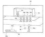
携帯用ゲーム機10の主記憶26にはゲーム空間(仮想的な3次元空間)が構築される。図3はこのゲーム空間の一例を示す図である。同図に示すように、ゲーム空間50にはサッカー球技場を表すフィールドオブジェクト52と、ゴールを表すゴールオブジェクト54と、が配置され、サッカーの試合の舞台となるフィールドが形成される。フィールドオブジェクト52上には、サッカー選手を表す選手オブジェクト56と、サッカーボールを表すボールオブジェクト58と、が配置される。同図では1体の選手オブジェクト56のみが表されているが、フィールドオブジェクト52上には、ユーザの操作対象チームに属する11体の選手オブジェクト56と、対戦相手チームに属する11体の選手オブジェクト56と、が配置される。
A game space (virtual three-dimensional space) is constructed in the main memory 26 of the portable game machine 10. FIG. 3 shows an example of this game space. As shown in the figure, a
操作対象チームに属する選手オブジェクト56のうちのいずれかがユーザの操作対象となる。ユーザの操作対象はボールオブジェクト58の移動等に応じて切り替えられる。ユーザの操作対象の選手オブジェクト56(以下、操作対象選手オブジェクトと記載する。)は、操作キー部46に対する操作内容に応じて各種動作を行う。なお、操作対象チームに属する選手オブジェクト56のうちの操作対象選手オブジェクト以外の選手オブジェクト56と、対戦相手チームに属する選手オブジェクト56(以下、対戦相手選手オブジェクトと記載する。)とは、コンピュータによって所定のアルゴリズムに従い自動制御される。
Any of the player objects 56 belonging to the operation target team is the user's operation target. The user's operation target is switched according to the movement of the
ゲーム空間50には例えばボールオブジェクト58に従動する仮想カメラが設定される。この仮想カメラから見えるゲーム空間50の様子を表すゲーム画面がタッチスクリーン22に表示される。ユーザは、タッチスクリーン22に表示されるゲーム画面を見ながら操作キー部46を操作し、操作対象選手オブジェクトに対する各種動作指示を行う。
For example, a virtual camera that follows the
上記サッカーゲームでは、対戦相手選手オブジェクトによるファウルイベントが発生すると、操作対象選手オブジェクトにフリーキックを行わせるためのフリーキック画面がタッチスクリーン22に表示される。
In the soccer game, when a foul event is generated by the opponent player object, a free kick screen for causing the operation target player object to perform a free kick is displayed on the
図4はフリーキック画面の一例を示している。同図に示すフリーキック画面60には、フリーキック位置に配置されたボールオブジェクト58と、フリーキック位置に基づく位置に配置された操作対象選手オブジェクト56aと、いわゆる「カベ」を形成するように配置された複数の対戦相手選手オブジェクト56bと、ゴールキーパーの対戦相手選手オブジェクト56cと、が表示されている。
FIG. 4 shows an example of a free kick screen. In the
フリーキック画面60にはゲージ64が表示される。ゲージ64は、矩形状の枠画像64aと、枠画像64a内に左詰で配置される伸張画像64bと、を含んでいる。伸張画像64bはフリーキックボタンの押下に応じて伸張する。具体的には、フリーキックボタン(本実施の形態ではボタン26a)が押下される前、伸張画像64bの左端が枠画像64aの左端に重なった状態になっており、伸張画像64bの長さは零になっている。フリーキックボタンが押下されると、伸張画像64bの伸張が開始され、フリーキックボタンの押下が継続される間、時間経過に伴って、伸張画像64bは右方向に一定速度で伸張する。そして、フリーキックボタンの押下が解除されると、伸張画像64bの伸張は停止される。伸張画像64bの長さはフリーキックボタンの押下時間(フリーキックボタンの押下が開始されてからその押下が解除されるまでの時間)の長さを示すことになる。後述するように、伸張画像64bの長さはボールオブジェクト58の軌道の決定の基礎とされる。なお以下では、伸張画像64bの長さを単に「ゲージ長」と記載する。
A
ユーザは、フリーキック画面60において、まずフリーキックの基本方向62を設定する。基本方向62は、フリーキックが行われた場合のボールオブジェクト58の軌道の決定の基礎とされる。操作対象選手オブジェクト56aよってフリーキックが行われると、ボールオブジェクト58は原則として基本方向62に向かって移動することになる。基本方向62の設定には例えばボタン26lやボタン26rが用いられる。ユーザがボタン26l又はボタン26rを押下すると、基本方向62がフリーキック位置を中心に左又は右に回転してなる方向に変更される。
The user first sets the
ユーザはフリーキックの基本方向62を設定したら、フリーキックボタンを押下する。フリーキックボタンが押下されると、操作対象選手オブジェクト56aによってフリーキックが行われ、ボールオブジェクト58が移動を開始する。このとき、ボールオブジェクト58の軌道は、ユーザによって設定された基本方向62と、ゲージ長と、方向ボタン24の押下状態と、に基づいて決定される。
When the user sets the
例えば、ボールオブジェクト58の初速度及び蹴り出し角度がゲージ長に基づいて決定される。ここで、蹴り出し角度とは、図5に示すように、ボールオブジェクト58が蹴り出される方向と、フィールドオブジェクト52と、がなす角度(θ)である。ゲージ長が長くなると、ボールオブジェクト58の初速度v0は速くなり、ボールオブジェクト58の蹴り出し角度θは大きくなる。
For example, the initial speed and kicking angle of the
携帯用ゲーム機10には、ゲージ長とボールオブジェクト58の初速度とを対応づけてなる情報や、ゲージ長とボールオブジェクト58の蹴り出し角度とを対応づけてなる情報が記憶されている。例えば、ボールオブジェクト58の初速度をゲージ長から算出するための演算式や、ボールオブジェクト58の蹴り出し角度をゲージ長から算出するための演算式が記憶されている。ボールオブジェクト58の初速度及び蹴り出し角度は、それらの情報(演算式)に基づいて決定される。
The portable game machine 10 stores information that associates the gauge length with the initial velocity of the
また例えば、フリーキックボタンの押下が解除されたタイミング等において、上方向指示部24uが押下されていると、ボールオブジェクト58の軌道は高くなり、下方向指示部24dが押下されていると、ボールオブジェクト58の軌道は低くなる。
Also, for example, when the
携帯用ゲーム機10には、ボールオブジェクト58の初速度v0をゲージ長sから算出するための演算式として下記式(1),(3),(5)が記憶されている。また、ボールオブジェクト58の蹴り出し角度θをゲージ長sから算出するための演算式として下記式(2),(4),(6)が記憶されている。すなわち、ボールオブジェクト58の初速度v0及び蹴り出し角度θをゲージ長sから算出するための関数の組み合わせとして、関数f1及びg1と、関数f2及びg2と、関数f3及びg3と、の3種類が記憶されている。 The portable game machine 10 stores the following formulas (1), (3), and (5) as calculation formulas for calculating the initial velocity v 0 of the ball object 58 from the gauge length s. Further, the following formulas (2), (4), and (6) are stored as calculation formulas for calculating the kicking angle θ of the ball object 58 from the gauge length s. That is, as a combination of functions for calculating the initial velocity v 0 and the kicking angle θ of the ball object 58 from the gauge length s, functions f 1 and g 1 , functions f 2 and g 2 , functions f 3 and g 3 are stored.
v0=f1(s) ・・・ (1)
θ=g1(s) ・・・ (2)
v 0 = f 1 (s) (1)
θ = g 1 (s) (2)
v0=f2(s) ・・・ (3)
θ=g2(s) ・・・ (4)
v 0 = f 2 (s) (3)
θ = g 2 (s) (4)
v0=f3(s) ・・・ (5)
θ=g3(s) ・・・ (6)
v 0 = f 3 (s) (5)
θ = g 3 (s) (6)
ここで、関数f1及びg1は、関数f2及びg2や関数f3及びg3に比べて、同じゲージ長sに対応するボールオブジェクト58の軌道が低くなるように(蹴り出し角度θの最大値が関数f2及びg2や関数f3及びg3の場合に比べて小さく)設定され、下方向指示部24dが押下された場合に用いられる。関数f3及びg3は、関数f1及びg1や関数f2及びg2に比べて、同じゲージ長sに対応するボールオブジェクト58の軌道が高くなるように(蹴り出し角度θの最大値が関数f1及びg1や関数f2及びg2の場合に比べて大きく)設定され、上方向指示部24uが押下された場合に用いられる。関数f2及びg2は、同じゲージ長sに対応するボールオブジェクト58の軌道が関数f1及びg1と関数f3及びg3との中間になるように(蹴り出し角度θの最大値が関数f1及びg1と関数f2及びg2との中間になるように)設定され、上方向指示部24u及び下方向指示部24dが押下されていない場合に用いられる。
Here, the functions f 1 and g 1 are set so that the trajectory of the ball object 58 corresponding to the same gauge length s becomes lower than the functions f 2 and g 2 and the functions f 3 and g 3 (the kick angle θ Is set to be smaller than those of the functions f 2 and g 2 and the functions f 3 and g 3 ), and is used when the
また例えば、フリーキックボタンの押下が解除されたタイミング等において、左方向指示部24lが押下されていると、ボールオブジェクト58の軌道は左にカーブし、右方向指示部24rが押下されていると、ボールオブジェクト58の軌道は右にカーブする。
Also, for example, when the left direction indicating unit 24l is pressed at the timing when the free kick button is released, the trajectory of the ball object 58 curves to the left and the right
上記のようなフリーキック画面60では、ボールオブジェクト58の軌道を所望の軌道とするためにゲージ長をどの程度の長さにすればよいかや、方向ボタン24に対してどのような操作を行えばよいかをユーザが分からない場合がある。そのため、ボールオブジェクト58の軌道を所望の軌道とすることがユーザ(特に熟練度の低いユーザ)にとって困難な場合がある。この点、携帯用ゲーム機10では、ユーザはボールオブジェクト58の軌道を所望の軌道とすることができるように支援する機能(フリーキック操作支援機能)が用意されている。
In the
具体的には、フリーキック画面60において、例えば図6に示すように、ユーザがタッチパネル22bを押圧することによって所望の軌道(所望軌道66)を手書き入力すると、例えば図7に示すように、所望軌道66が実現されるような操作を案内する画像(方向指示操作案内画像68、ゲージ長案内画像69)が表示される。
Specifically, on the
方向指示操作案内画像68は、所望軌道66が実現されるような方向ボタン24の操作内容を案内する画像である。この方向指示操作案内画像68によって、ユーザは、所望軌道66が実現されるようにするために、方向ボタン24をどのように押下すればよいかを知ることができるようになる。なお、図7に示す方向指示操作案内画像68は、上方向指示部24u及び右方向指示部24rを押下すべきことを示している。
The direction instruction
ゲージ長案内画像69は、所望軌道66が実現されるようなゲージ長を案内する画像である。このゲージ長案内画像69によって、ユーザは、所望軌道66が実現されるようにするために、ゲージ長をどの程度にすればよいかを知ることができるようになる。言い換えれば、ゲージ長案内画像69は、所望軌道66が実現されるようなフリーキックボタンの操作を案内する画像であり、このゲージ長案内画像69によって、ユーザは、フリーキックボタンをどの程度押下し続ければよいか(どのタイミングでフリーキックボタンの押下を解除すればよいか)を知ることができるようになる。
The gauge
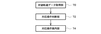
次に、フリーキック操作支援機能を実現するための構成について説明する。図8は、携帯用ゲーム機10で実現される機能のうち、フリーキック操作支援機能に関連するものを主として示す機能ブロック図である。同図に示すように、携帯用ゲーム機10は所望軌道データ取得部70、対応操作判断部72、対応操作案内部74を機能的に含んでいる。これらの機能は、ゲームカード42から読み出されるゲームプログラムが携帯用ゲーム機10で実行されることによって実現する。
Next, a configuration for realizing the free kick operation support function will be described. FIG. 8 is a functional block diagram mainly showing functions related to the free kick operation support function among the functions realized by the portable game machine 10. As shown in the figure, the portable game machine 10 functionally includes a desired trajectory
[1.所望軌道データ取得部]
所望軌道データ取得部70はタッチパネル22b、マイクロプロセッサ34及び主記憶36を主として実現される。所望軌道データ取得部70はボールオブジェクト58の所望軌道66の手書き入力を受け付け、ユーザによって手書き入力された所望軌道66を示す所望軌道データを取得する。本実施の形態の場合、所望軌道データ取得部70は、タッチパネル22bの押圧位置を示す位置情報を所定時間(例えば1/60秒)ごとに取得する。フリーキック画面60において図6に示すような所望軌道66が手書きされた場合、例えば図9に示すような位置情報列が所望軌道データとして取得される。
[1. Desired trajectory data acquisition unit]
The desired trajectory
[2.対応操作判断部]
対応操作判断部72はマイクロプロセッサ34及び主記憶36を主として実現される。対応操作判断部72は、ユーザによって手書き入力された所望軌道66に対応する操作内容を、所望軌道データ取得部70によって取得された所望軌道データに基づいて判断する。本実施の形態の場合、所望軌道66が実現されるような、左方向指示部24l及び右方向指示部24rの操作内容と、上方向指示部24u及び下方向指示部24dの操作内容と、ゲージ長と、が判断される。
[2. Corresponding operation determination unit]
The corresponding
ここで、所望軌道66が実現されるような操作内容を判断するための処理について説明する。図10乃至図12はこの処理を示すフロー図である。この処理を実行するためのプログラムがゲームカード42から読み出され、マイクロプロセッサ34によって実行されることによって、対応操作判断部72が実現される。
Here, a process for determining the operation content for realizing the desired
この処理では、まず、所望軌道66が実現されるような左方向指示部24l及び右方向指示部24rの操作内容を判断するための処理(図10)が実行される。この処理では、所望軌道66のフリーキックの基本方向62に対する曲がり具合が判断され、その判断結果に基づいて、左方向指示部24l及び右方向指示部24rを押下する必要があるか否かが判断される。図13はこの処理の内容を説明するための図である。
In this process, first, a process (FIG. 10) for determining the operation content of the left direction instructing unit 24l and the right
図10に示すように、まず、所望軌道66の終点に対応するゲーム空間50内の位置Pが取得される(S101:図13参照)。このステップでは、位置Pがゴールポスト55とクロスバー53とゴールライン51とによって囲まれる領域内の位置であると仮定して、位置Pが取得される。具体的には、各ゴールポスト55の両端55a,55b,55c,55dのフリーキック画面60における表示位置が取得される。次に、ゴールポスト55の両端55a,55b,55c,55dのフリーキック画面60における表示位置と、所望軌道66の終点の位置と、の相対的位置関係が取得される。そして、位置Pが、ゲーム空間50におけるゴールポスト55の両端55a,55b,55c,55dの位置と、上記相対的位置関係と、に基づいて取得される。
As shown in FIG. 10, first, a position P in the
次に、位置Pをフィールドオブジェクト52上に正射影してなる位置P’が取得される(S102:図13参照)。そして、フリーキック位置Oから基本方向62を見た場合において、フリーキック位置Oから位置P’への方向OP’が基本方向62に対して左側であるか否かが判断される(S103:図13参照)。
Next, a position P ′ obtained by orthogonally projecting the position P onto the
方向OP’が基本方向62に対して左側である場合は、ボールオブジェクト58の軌道を左にカーブさせる必要がある場合である。すなわち、左方向指示部24lを押下する必要がある場合である。この場合、左方向指示フラグが1に設定され、右方向指示フラグが0に設定される(S104)。ここで、左方向指示フラグは左方向指示部24lを押下する必要があるか否かを示す情報である。左方向指示フラグは、左方向指示部24lを押下する必要がないと判断される場合に0に設定され、左方向指示部24lを押下する必要があると判断される場合に1に設定される。また、右方向指示フラグは右方向指示部24rを押下する必要があるか否かを示す情報である。右方向指示フラグは、右方向指示部24rを押下する必要がないと判断される場合に0に設定され、右方向指示部24rを押下する必要があると判断される場合に1に設定される。
The case where the direction OP ′ is on the left side with respect to the
一方、方向OP’が基本方向62に対して左側でない場合、フリーキック位置Oから基本方向62を見た場合において方向OP’が基本方向62に対して右側であるか否かが判断される(S105:図13参照)。方向OP’が基本方向62に対して右側である場合は、ボールオブジェクト58の軌道を右にカーブさせる必要がある場合である。すなわち、右方向指示部24rを押下する必要がある場合である。この場合、左方向指示フラグが0に設定され、右方向指示フラグが1に設定される(S106)。一方、方向OP’が基本方向62に対して右側でない場合は、ボールオブジェクト58の軌道をカーブさせる必要がない場合である。すなわち、左方向指示部24l及び右方向指示部24rを押下する必要がない場合である。この場合、左方向指示フラグが0に設定され、右方向指示フラグが0に設定される(S107)。
On the other hand, when the direction OP ′ is not on the left side with respect to the
次に、所望軌道66が実現されるような上方向指示部24u及び下方向指示部24dの操作内容を判断するための処理(図11)が実行される。ユーザによって手書き入力された所望軌道66が直線的である場合(すなわち、所望軌道66の曲がり具合が小さい場合)には、ボールオブジェクト58の軌道が低い軌道となることをユーザが望んでいるものと推測できる。逆に、ユーザによって手書き入力された所望軌道66の曲がり具合が大きい場合には、ボールオブジェクト58の軌道が高い軌道となることをユーザが望んでいるものと推測できる。このため、この処理では、所望軌道66の曲がり具合を判断し、その判断結果に基づいて、上方向指示部24u及び下方向指示部24dを押下する必要があるか否かが判断される。図14はこの処理の内容を説明するための図である。
Next, a process (FIG. 11) for determining the operation content of the upward
図14に示すように、まず、所望軌道66の始点Q1(フリーキック位置O)からその次の点Q2への方向と、終点Qnの1つ前の点Qn−1から終点Qnへの方向と、のなす角度θqが取得される(S108:図11参照)。 As shown in FIG. 14, first, desired from the start point of the track 66 Q 1 (free kick position O) and the direction to the next point Q 2, the end point in terms Q n-1 of the previous endpoint Q n Q An angle θq formed by the direction to n is acquired (S108: see FIG. 11).
そして、角度θqが0≦θq<θ1であるか否かが判断される(S109)。ここで、θ1は所定の基準角度である。角度θqが0≦θq<θ1である場合は、所望軌道66が直線的である(曲がり具合が小さい)と判断される場合である。すなわち、ボールオブジェクト58の軌道を低くするために、下方向指示部24dを押下する必要があると判断される場合である。この場合、上方向指示フラグが0に設定され、下方向指示フラグが1に設定される(S110)。ここで、上方向指示フラグは上方向指示部24uを押下する必要があるか否かを示す情報である。上方向指示フラグは、上方向指示部24uを押下する必要がないと判断される場合に0に設定され、上方向指示部24uを押下する必要があると判断される場合に1に設定される。また、下方向指示フラグは下方向指示部24dを押下する必要があるか否かを示す情報である。下方向指示フラグは、下方向指示部24dを押下する必要がないと判断される場合に0に設定され、下方向指示部24dを押下する必要があると判断される場合に1に設定される。
Then, it is determined whether or not the angle θq is 0 ≦ θq <θ1 (S109). Here, θ1 is a predetermined reference angle. When the angle θq is 0 ≦ θq <θ1, it is determined that the desired
一方、角度θqが0≦θq<θ1でない場合、角度θqがθ2≦θqであるか否かが判断される(S111)。ここで、θ2は所定の基準角度であり、θ1よりも大きい角度である。角度θqがθ2≦θqである場合は、所望軌道66の曲がり具合が大きいと判断される場合である。すなわち、ボールオブジェクト58の軌道を高くするために、上方向指示部24uを押下する必要があると判断される場合である。この場合、上方向指示フラグが1に設定され、下方向指示フラグが0に設定される(S112)。また、角度θqがθ2≦θqでない場合(すなわち、角度θqがθ1≦θq<θ2である場合)、上方向指示部24u及び下方向指示部24dを押下する必要がないと判断され、上方向指示フラグ及び下方向指示フラグが0に設定される(S113)。
On the other hand, if the angle θq is not 0 ≦ θq <θ1, it is determined whether or not the angle θq is θ2 ≦ θq (S111). Here, θ2 is a predetermined reference angle, which is an angle larger than θ1. If the angle θq is θ2 ≦ θq, it is determined that the degree of bending of the desired
次に、所望軌道66が実現されるようなゲージ長を判断するための処理(図12)が実行される。図15はこの処理の内容を説明するための図である。
Next, a process (FIG. 12) for determining a gauge length that realizes the desired
図15に示すように、まず、所望軌道66の終点に対応するゲーム空間50上の位置Pの高さh(フィールドオブジェクト52からの高さ)が取得される(S114:図12参照)。なお、位置PはS101で取得されている。
As shown in FIG. 15, first, the height h (height from the field object 52) of the position P on the
また、フリーキック位置Oと、位置Pをフィールドオブジェクト52上に正射影してなる位置P’と、の間の距離dが取得される(S115:図15参照)。
Further, the distance d between the free kick position O and the position P ′ obtained by orthogonally projecting the position P onto the
次に、S114で取得された高さhと、S115で取得された距離dと、に基づいてゲージ長sが取得される(S116)。 Next, the gauge length s is acquired based on the height h acquired in S114 and the distance d acquired in S115 (S116).
ここで、ボールオブジェクト58の初速度v0及び蹴り出し角度θと、高さh及び距離dとは、下記式(7)及び(8)の関係を有している。なお、式(7)及び(8)においてtはボールオブジェクト58が蹴り出されてからの経過時間を示し、式(8)においてgは重力加速度を示している。
Here, the initial velocity v 0 and the kicking angle θ of the
v0・cosθ・t=d ・・・ (7)
v0・sinθ・t−(g・t2/2)=h ・・・ (8)
v 0 · cos θ · t = d (7)
v 0 · sinθ · t- (g · t 2/2) = h ··· (8)
上方向指示フラグが1に設定されている場合には、上記式(7)及び(8)に上記式(5)及び(6)に代入することによって得られる連立方程式(9)及び(10)を解くことによって、ゲージ長sが取得される。 When the upward direction flag is set to 1, simultaneous equations (9) and (10) obtained by substituting the above formulas (7) and (8) into the above formulas (5) and (6). To obtain the gauge length s.
f3(s)・cos(g3(s))・t=d ・・・ (9)
f3(s)・sin(g3(s))・t−(g・t2/2)=h ・・・ (10)
f 3 (s) · cos (g 3 (s)) · t = d (9)
f 3 (s) · sin ( g 3 (s)) · t- (g · t 2/2) = h ··· (10)
同様に、下方向指示フラグが1に設定されている場合には、上記式(7)及び(8)に上記式(1)及び(2)に代入することによって得られる連立方程式(11)及び(12)を解くことによって、ゲージ長sが取得される。 Similarly, when the downward direction flag is set to 1, the simultaneous equations (11) and (11) obtained by substituting the above expressions (1) and (2) into the above expressions (7) and (8) By solving (12), the gauge length s is obtained.
f1(s)・cos(g1(s))・t=d ・・・ (11)
f1(s)・sin(g1(s))・t−(g・t2/2)=h ・・・ (12)
f 1 (s) · cos (g 1 (s)) · t = d (11)
f 1 (s) · sin ( g 1 (s)) · t- (g · t 2/2) = h ··· (12)
また、上方向指示フラグ及び下方向指示フラグがともに0に設定されている場合には、上記式(7)及び(8)に上記式(3)及び(4)に代入することによって得られる連立方程式(13)及び(14)を解くことによって、ゲージ長sが取得される。 When both the upward direction flag and the downward direction flag are set to 0, simultaneous equations obtained by substituting the above formulas (7) and (8) into the above formulas (3) and (4). The gauge length s is obtained by solving equations (13) and (14).
f2(s)・cos(g2(s))・t=d ・・・ (13)
f2(s)・sin(g2(s))・t−(g・t2/2)=h ・・・ (14)
f 2 (s) · cos (g 2 (s)) · t = d (13)
f 2 (s) · sin ( g 2 (s)) · t- (g · t 2/2) = h ··· (14)
[3.対応操作案内部]
対応操作案内部74は例えばマイクロプロセッサ34、画像処理部38や音声処理部44を主として実現される。対応操作案内部74は対応操作判断部72による判断結果をユーザに案内する。例えば、対応操作案内部74は対応操作判断部72による判断結果を案内する画像や音声等を出力させる。
[3. Corresponding operation guide]
The corresponding
本実施の形態に係る対応操作案内部74は、図10及び図11に示す処理によって設定され、主記憶36に記憶された上方向指示フラグ、下方向指示フラグ、左方向指示フラグ及び右方向指示フラグの値の組み合わせに対応する方向指示操作案内画像68をフリーキック画面60の所定位置に表示させる。例えば、上方向指示フラグ及び右方向指示フラグが1に設定され、下方向指示フラグ及び左方向指示フラグが0に設定されている場合、対応操作案内部74は、図7に示すような方向指示操作案内画像68をフリーキック画面60に表示させる。また対応操作案内部74は、フリーキック画面60におけるゲージ64の表示位置と、図12に示す処理によって得られ、主記憶36に記憶されたゲージ長sと、に基づく位置にゲージ長案内画像69を表示させる。すなわち、対応操作案内部74は、伸張画像64bの長さがゲージ長sとなるような位置にゲージ長案内画像69を表示させる。
The corresponding
以上説明した携帯用ゲーム機10によれば、ユーザはフリーキック画面60においてボールオブジェクト58の所望軌道66を手書きすると、所望軌道66が実現されるような操作内容が案内表示されるので、ボールオブジェクト58の軌道を所望の軌道とするためにどのような操作を行えばよいかを知ることができるようになる。特に、タッチスクリーン22にユーザが所望の軌道を手書きするという、極めて直感的なインタフェースを採用したので、ユーザはボールオブジェクト58の軌道が所望の軌道となるような操作を容易に知ることができる。
According to the portable game machine 10 described above, when the user handwrites the desired
なお、本発明は以上説明した実施の形態に限定されるものではない。 The present invention is not limited to the embodiment described above.
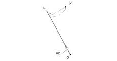
例えば、ユーザにとって手書き入力された所望軌道66が実現不可能と判断される場合には、その旨の警告メッセージが表示されるようにしてもよい。例えば、所望軌道66の曲がり具合が大きすぎるような場合には、その旨の警告メッセージが表示されるようにしてもよい。この場合、所望軌道66の曲がり具合が大きすぎるか否かは、例えば図16に示すように、位置P’(図13又は図15参照)から直線L(フリーキック位置Oから基本方向62への直線)への垂線の長さlが所定の基準値より大きいか否かを判断することによって判断するようにすればよい。例えば、上記長さlが所定の基準値よりも大きい場合には、所望軌道66が基本方向62に対して曲がりすぎていると判断し、所望軌道66の曲がり具合が大きすぎる旨の警告メッセージを表示するようにしてもよい。
For example, when it is determined that the desired
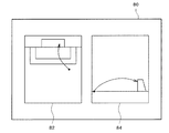
また例えば、ユーザによって所望軌道66が入力された場合、例えば図17に示すような所望軌道確認画面80を第1液晶表示パネル18(又はタッチスクリーン22)に表示させるようにしてもよい。同図に示す所望軌道確認画面80には、所望軌道66を真上から見た様子を表す所望軌道画像82と、所望軌道66を真横から見た様子を表す所望軌道画像84と、を表示されている。このようにすれば、ユーザは所望軌道66が本当に自らが所望するものであるか否かを確認できるようになる。
Further, for example, when the desired
また例えば、携帯用ゲーム機10は、基準所望軌道データと、操作内容データ(上、下、左及び右方向指示フラグとゲージ長)と、を対応づけてなるテーブルを記憶するようにしてもよい。そして、ユーザによって所望軌道データが手書き入力された場合には、ユーザによって手書き入力された所望軌道データと、各基準所望軌道データと、の類似度を算出し、最も類似度の高い基準所望軌道データに対応づけられた操作内容データに基づいて、所望軌道66に対応する操作が案内されるようにしてもよい。
Further, for example, the portable game machine 10 may store a table in which the reference desired trajectory data and the operation content data (up, down, left and right direction instruction flags and gauge length) are associated with each other. . When the desired trajectory data is input by handwriting by the user, the similarity between the desired trajectory data input by handwriting by the user and each reference desired trajectory data is calculated, and the reference desired trajectory data with the highest similarity is calculated. The operation corresponding to the desired
また例えば、上記サッカーゲームには、ユーザがフリーキック操作の練習を行うための練習モードを設けるようにしてもよい。そして、この練習モードでのみフリーキック操作支援機能を有効としてもよい。 For example, the soccer game may be provided with a practice mode for the user to practice a free kick operation. The free kick operation support function may be enabled only in this practice mode.
また例えば、本発明が適用されるのはサッカーゲームに限られない。例えばサッカーゲーム以外のスポーツゲーム(ボールやパック等の移動体を用いて行われるバスケットボールやアイスホッケー等)にも本発明は適用することができる。また例えば、本発明をレースゲームに適用することによって、ユーザが所望のコース取りを手書き入力すると、所望のコース取りに従って自動車オブジェクト(移動体)を走行させるための操作内容が案内されるようにしてもよい。本発明は、移動体がゲーム空間において操作手段に対する操作内容に応じた軌道を移動するゲームに適用することができる。 For example, the present invention is not limited to a soccer game. For example, the present invention can also be applied to sports games other than soccer games (basketball, ice hockey, etc. performed using a moving body such as a ball or a pack). Further, for example, by applying the present invention to a racing game, when a user inputs a desired course by handwriting, an operation content for driving an automobile object (moving body) according to the desired course is guided. Also good. The present invention can be applied to a game in which a moving body moves in a trajectory according to the operation content of the operation means in the game space.
また、以上の説明では、プログラムを情報記憶媒体たるゲームカード42から携帯用ゲーム機10に供給するようにしたが、通信ネットワークを介してプログラムを家庭等に配信するようにしてもよい。図18は、通信ネットワークを用いたプログラム配信システムの全体構成を示す図である。同図に基づいて本発明に係るプログラム配信方法を説明する。同図に示すように、このプログラム配信システム100は、ゲームデータベース102、サーバ104、通信ネットワーク106、携帯用ゲーム機108を含んでいる。このうち、ゲームデータベース102とサーバ104とによりプログラム配信装置110が構成される。通信ネットワーク106は、例えばインターネットやケーブルテレビネットワークを含んで構成されている。このシステムでは、ゲームデータベース(情報記憶媒体)102に、ゲームカード42の記憶内容と同様のプログラムが記憶されている。そして、携帯用ゲーム機108を用いて需要者がゲーム配信要求をすることにより、それが通信ネットワーク106を介してサーバ104に伝えられる。そして、サーバ104はゲーム配信要求に応じてゲームデータベース102からプログラムを読み出し、それを携帯用ゲーム機108(ゲーム配信要求元)に送信する。ここではゲーム配信要求に応じてゲーム配信するようにしたが、サーバ104から一方的に送信するようにしてもよい。また、必ずしも一度にゲームの実現に必要な全てのプログラムを配信(一括配信)する必要はなく、ゲームの局面に応じて必要な部分を配信(分割配信)するようにしてもよい。このように通信ネットワーク106を介してゲーム配信するようにすれば、プログラムを需要者は容易に入手することができるようになる。
In the above description, the program is supplied from the
10,108 携帯用ゲーム機、12 上部筐体、12a 表面、14 下部筐体、14a 表面、16 ヒンジ部、18 第1液晶表示パネル、20 スピーカ、22 タッチスクリーン、22a 第2液晶表示パネル、22b タッチパネル、24 方向ボタン、24u 上方向指示部、24d 下方向指示部、24l 左方向指示部、24r 右方向指示部、26a,26b,26x,26y,26l,26r ボタン、28 カードスロット、32 バス、34 マイクロプロセッサ、36 主記憶、38 画像処理部、40 入出力処理部、42 ゲームカード、44 音声処理部、46 操作キー部、50 ゲーム空間、51 ゴールライン、52 フィールドオブジェクト、53 クロスバー、54 ゴールオブジェクト、55 ゴールポスト、55a,55b,55c,55d 両端、56 選手オブジェクト、56a 操作対象選手オブジェクト、56b,56c 対戦相手選手オブジェクト、58 ボールオブジェクト、60 フリーキック画面、62 基本方向、64 ゲージ、64a 枠画像、64b 伸張画像、66 所望軌道、68 方向指示操作案内画像、69 ゲージ長案内画像、70 所望軌道データ取得部、72 対応操作判断部、74 対応操作案内部、80 所望軌道確認画面、82,84 所望軌道画像、100 プログラム配信システム、102 ゲームデータベース、104 サーバ、106 通信ネットワーク、110 プログラム配信装置。 10,108 portable game machine, 12 upper housing, 12a surface, 14 lower housing, 14a surface, 16 hinge portion, 18 first liquid crystal display panel, 20 speaker, 22 touch screen, 22a second liquid crystal display panel, 22b Touch panel, 24 direction button, 24u Up direction unit, 24d Down direction unit, 24l Left direction unit, 24r Right direction unit, 26a, 26b, 26x, 26y, 26l, 26r button, 28 card slot, 32 bus, 34 Microprocessor, 36 Main memory, 38 Image processing unit, 40 Input / output processing unit, 42 Game card, 44 Sound processing unit, 46 Operation key unit, 50 Game space, 51 Goal line, 52 Field object, 53 Crossbar, 54 Goal object, 55 Goal post, 55 a, 55b, 55c, 55d both ends, 56 player object, 56a operation target player object, 56b, 56c opponent player object, 58 ball object, 60 free kick screen, 62 basic direction, 64 gauge, 64a frame image, 64b expanded image , 66 desired trajectory, 68 direction instruction operation guide image, 69 gauge length guidance image, 70 desired trajectory data acquisition unit, 72 corresponding operation determination unit, 74 corresponding operation guide unit, 80 desired trajectory confirmation screen, 82, 84 desired trajectory image, 100 program distribution system, 102 game database, 104 server, 106 communication network, 110 program distribution apparatus.
Claims (4)
ユーザによって前記タッチパネルを用いて手書き入力された所望軌道を示す所望軌道データを取得する所望軌道データ取得手段と、
前記所望軌道データ取得手段によって取得された所望軌道データに基づいて、前記所望軌道に対応する前記操作ボタンの操作内容を判断する対応操作判断手段と、
前記対応操作判断手段によって判断された前記操作ボタンの操作内容を前記ユーザに案内する画像又は音声を出力する対応操作案内手段と、
を含むことを特徴とするゲーム装置。 In a game device that executes a game that includes a touch panel and operation buttons, and a moving body arranged in the game space moves on a trajectory determined based on the operation content of the operation buttons ,
Desired trajectory data acquisition means for acquiring desired trajectory data indicating a desired trajectory input by hand using the touch panel by a user;
Corresponding operation determining means for determining the operation content of the operation button corresponding to the desired trajectory based on the desired trajectory data acquired by the desired trajectory data acquiring means;
Corresponding operation guidance means for outputting an image or sound for guiding the operation content of the operation button determined by the corresponding operation determination means to the user;
A game apparatus comprising:
前記対応操作判断手段は、前記所望軌道データ取得手段によって取得された所望軌道データに基づいて、前記所望軌道の曲がり具合を判断する曲がり具合判断手段を含み、前記曲がり具合判断手段による判断結果に基づいて、前記所望軌道に対応する前記操作ボタンの操作内容を判断することを特徴とするゲーム装置。 The game device according to claim 1,
The corresponding operation judging means, said desired trajectory data obtained based on the desired trajectory data obtained by the means, the include curvature determination means determines the desired trajectory of curvature, the result of determination by said bending tool Ivan cross section Based on the game device, the operation content of the operation button corresponding to the desired trajectory is determined.
所望軌道データ取得手段が、ユーザによって前記タッチパネルを用いて手書き入力された所望軌道を示す所望軌道データを取得する所望軌道データ取得ステップと、
対応操作判断手段が、前記所望軌道データ取得ステップで取得された所望軌道データに基づいて、前記所望軌道に対応する前記操作ボタンの操作内容を判断する対応操作判断ステップと、
対応操作案内手段が、前記対応操作判断ステップで判断された前記操作ボタンの操作内容を前記ユーザに案内する画像又は音声を出力する対応操作案内ステップと、
を含むことを特徴とするゲーム装置の制御方法。 In a control method of a game device that includes a touch panel and operation buttons, and that executes a game in which a moving body arranged in a game space moves on a trajectory determined based on the operation content of the operation buttons ,
Desired trajectory data acquiring means, the desired trajectory data to that Nozomu Tokoro orbit data acquisition step acquires indicating a desired trajectory input in handwriting using the touch panel by a user,
Corresponding operation judgment means, and said desired trajectory data obtained based on the obtained desired trajectory data was in step, to that pair応操operation determining step determines the operation contents of the operation button corresponding to the desired track,
Corresponding operation guidance means, the corresponding operation guidance step of outputting image or voice for guiding the operation contents of the operation buttons is determined by the corresponding operation judging step to the user,
A method for controlling a game device, comprising:
ユーザによって前記タッチパネルを用いて手書き入力された所望軌道を示す所望軌道データを取得する所望軌道データ取得手段、
前記所望軌道データ取得手段によって取得された所望軌道データに基づいて、前記所望軌道に対応する前記操作ボタンの操作内容を判断する対応操作判断手段、及び、
前記対応操作判断手段によって判断された前記操作ボタンの操作内容を前記ユーザに案内する画像又は音声を出力する対応操作案内手段、
として前記コンピュータを機能させるためのプログラム。
A program for causing a computer including a touch panel and operation buttons to function as a game device that executes a game in which a moving body arranged in a game space moves on a trajectory determined based on the operation content of the operation buttons. ,
Desired trajectory data acquisition means for acquiring desired trajectory data indicating a desired trajectory input by handwriting by the user using the touch panel;
Corresponding operation determination means for determining the operation content of the operation button corresponding to the desired trajectory based on the desired trajectory data acquired by the desired trajectory data acquisition means, and
Corresponding operation guidance means for outputting an image or sound for guiding the user to the operation content of the operation button determined by the corresponding operation determination means;
A program for causing the computer to function as
Priority Applications (5)
| Application Number | Priority Date | Filing Date | Title |
|---|---|---|---|
| JP2006091966A JP4971659B2 (en) | 2006-03-29 | 2006-03-29 | GAME DEVICE, GAME DEVICE CONTROL METHOD, AND PROGRAM |
| KR1020087026408A KR101035529B1 (en) | 2006-03-29 | 2006-12-18 | Game machine, game machine control method, and information storage medium |
| US12/295,223 US20090118011A1 (en) | 2006-03-29 | 2006-12-18 | Game machine, game machine control method, and information storage medium |
| PCT/JP2006/325184 WO2007111011A1 (en) | 2006-03-29 | 2006-12-18 | Game machine, game machine control method, and information storage medium |
| TW096101214A TWI320323B (en) | 2006-03-29 | 2007-01-12 | Game device, controlling method of the same and information stored media |
Applications Claiming Priority (1)
| Application Number | Priority Date | Filing Date | Title |
|---|---|---|---|
| JP2006091966A JP4971659B2 (en) | 2006-03-29 | 2006-03-29 | GAME DEVICE, GAME DEVICE CONTROL METHOD, AND PROGRAM |
Publications (3)
| Publication Number | Publication Date |
|---|---|
| JP2007260268A JP2007260268A (en) | 2007-10-11 |
| JP2007260268A5 JP2007260268A5 (en) | 2009-06-18 |
| JP4971659B2 true JP4971659B2 (en) | 2012-07-11 |
Family
ID=38540946
Family Applications (1)
| Application Number | Title | Priority Date | Filing Date |
|---|---|---|---|
| JP2006091966A Active JP4971659B2 (en) | 2006-03-29 | 2006-03-29 | GAME DEVICE, GAME DEVICE CONTROL METHOD, AND PROGRAM |
Country Status (5)
| Country | Link |
|---|---|
| US (1) | US20090118011A1 (en) |
| JP (1) | JP4971659B2 (en) |
| KR (1) | KR101035529B1 (en) |
| TW (1) | TWI320323B (en) |
| WO (1) | WO2007111011A1 (en) |
Families Citing this family (5)
| Publication number | Priority date | Publication date | Assignee | Title |
|---|---|---|---|---|
| KR101267563B1 (en) * | 2011-12-09 | 2014-01-06 | (주)네오위즈게임즈 | Method and system for providing free_kick game |
| JP5728550B2 (en) * | 2013-10-16 | 2015-06-03 | 株式会社タイトー | Game device, game program |
| JP5918285B2 (en) * | 2014-02-14 | 2016-05-18 | 株式会社コナミデジタルエンタテインメント | Movement control apparatus and program |
| JP6206781B2 (en) * | 2016-04-01 | 2017-10-04 | 株式会社コナミデジタルエンタテインメント | Movement control apparatus and program |
| CN109949406B (en) * | 2019-02-27 | 2023-05-26 | Oppo广东移动通信有限公司 | Model action processing method and device, storage medium and electronic equipment |
Family Cites Families (13)
| Publication number | Priority date | Publication date | Assignee | Title |
|---|---|---|---|---|
| JPS60182977A (en) * | 1984-02-29 | 1985-09-18 | カシオ計算機株式会社 | Electronic game apparatus |
| JP2001125552A (en) * | 1999-10-26 | 2001-05-11 | Hudson Soft Co Ltd | Image display device |
| JP2002035411A (en) * | 2000-05-15 | 2002-02-05 | Namco Ltd | Game system, sign recognition system, processing method for game and recording medium on which game program is recorded |
| JP3426588B2 (en) * | 2001-07-12 | 2003-07-14 | コナミ株式会社 | GAME DEVICE, GAME CONTROL METHOD, AND PROGRAM |
| JP3839354B2 (en) * | 2002-06-03 | 2006-11-01 | 株式会社Snkプレイモア | game machine |
| US8038527B2 (en) * | 2003-03-04 | 2011-10-18 | Walker Digital, Llc | Method and system for managing game confirmations |
| JP4213011B2 (en) * | 2003-03-10 | 2009-01-21 | 任天堂株式会社 | GAME DEVICE AND GAME PROGRAM |
| JP3699718B2 (en) * | 2003-10-31 | 2005-09-28 | コナミ株式会社 | GAME DEVICE, GAME DEVICE CONTROL METHOD, AND PROGRAM |
| JP3703473B2 (en) * | 2004-02-09 | 2005-10-05 | 任天堂株式会社 | GAME DEVICE AND GAME PROGRAM |
| CA2462620A1 (en) * | 2004-03-30 | 2005-09-30 | Jvl Corporation | Pool video game |
| JP4469653B2 (en) * | 2004-05-06 | 2010-05-26 | 任天堂株式会社 | Game system and game program |
| JP4626182B2 (en) * | 2004-05-14 | 2011-02-02 | 株式会社セガ | Battle game processing method, battle game system, program thereof, and storage medium |
| JP2006192246A (en) * | 2004-12-13 | 2006-07-27 | Nintendo Co Ltd | Game device and game program |
-
2006
- 2006-03-29 JP JP2006091966A patent/JP4971659B2/en active Active
- 2006-12-18 US US12/295,223 patent/US20090118011A1/en not_active Abandoned
- 2006-12-18 KR KR1020087026408A patent/KR101035529B1/en not_active IP Right Cessation
- 2006-12-18 WO PCT/JP2006/325184 patent/WO2007111011A1/en active Application Filing
-
2007
- 2007-01-12 TW TW096101214A patent/TWI320323B/en not_active IP Right Cessation
Also Published As
| Publication number | Publication date |
|---|---|
| TW200735935A (en) | 2007-10-01 |
| KR101035529B1 (en) | 2011-05-23 |
| JP2007260268A (en) | 2007-10-11 |
| US20090118011A1 (en) | 2009-05-07 |
| TWI320323B (en) | 2010-02-11 |
| WO2007111011A1 (en) | 2007-10-04 |
| KR20080114828A (en) | 2008-12-31 |
Similar Documents
| Publication | Publication Date | Title |
|---|---|---|
| JP3868450B2 (en) | GAME DEVICE, GAME DEVICE CONTROL METHOD, AND PROGRAM | |
| JP4837988B2 (en) | GAME DEVICE, GAME DEVICE CONTROL METHOD, AND PROGRAM | |
| US8172657B2 (en) | Game machine, game machine control method, and information storage medium | |
| JP4498448B2 (en) | GAME DEVICE, GAME DEVICE CONTROL METHOD, AND PROGRAM | |
| JP5048271B2 (en) | GAME PROGRAM AND GAME DEVICE | |
| JP4838223B2 (en) | GAME DEVICE, GAME DEVICE CONTROL METHOD, AND PROGRAM | |
| JP5214215B2 (en) | GAME DEVICE, GAME DEVICE CONTROL METHOD, AND PROGRAM | |
| JP4971659B2 (en) | GAME DEVICE, GAME DEVICE CONTROL METHOD, AND PROGRAM | |
| WO2007074569A1 (en) | Game machine, control method of game machine and information storage medium | |
| JP5192779B2 (en) | GAME DEVICE, GAME DEVICE CONTROL METHOD, AND PROGRAM | |
| US20080297492A1 (en) | Storage medium storing movement controlling program and movement controlling apparatus | |
| JP4928809B2 (en) | GAME DEVICE, GAME DEVICE CONTROL METHOD, AND PROGRAM | |
| US20070078006A1 (en) | Game program | |
| JP5419655B2 (en) | GAME DEVICE, GAME DEVICE CONTROL METHOD, AND PROGRAM | |
| JP5017155B2 (en) | GAME DEVICE, GAME DEVICE CONTROL METHOD, AND PROGRAM | |
| JP4040658B2 (en) | GAME DEVICE, GAME DEVICE CONTROL METHOD, AND PROGRAM | |
| JP2005342120A (en) | Game device, game controlling method and program | |
| JP5536467B2 (en) | GAME DEVICE, GAME DEVICE CONTROL METHOD, AND PROGRAM | |
| JP5449432B2 (en) | GAME PROGRAM AND GAME DEVICE | |
| JP2010162115A (en) | Game apparatus, control method of game apparatus, and program | |
| JP2003033570A (en) | Video game system, recording medium, and program |
Legal Events
| Date | Code | Title | Description |
|---|---|---|---|
| A621 | Written request for application examination |
Free format text: JAPANESE INTERMEDIATE CODE: A621 Effective date: 20090324 |
|
| A521 | Request for written amendment filed |
Free format text: JAPANESE INTERMEDIATE CODE: A523 Effective date: 20090423 |
|
| A131 | Notification of reasons for refusal |
Free format text: JAPANESE INTERMEDIATE CODE: A131 Effective date: 20110621 |
|
| A521 | Request for written amendment filed |
Free format text: JAPANESE INTERMEDIATE CODE: A523 Effective date: 20110819 |
|
| TRDD | Decision of grant or rejection written | ||
| A01 | Written decision to grant a patent or to grant a registration (utility model) |
Free format text: JAPANESE INTERMEDIATE CODE: A01 Effective date: 20120403 |
|
| A01 | Written decision to grant a patent or to grant a registration (utility model) |
Free format text: JAPANESE INTERMEDIATE CODE: A01 |
|
| A61 | First payment of annual fees (during grant procedure) |
Free format text: JAPANESE INTERMEDIATE CODE: A61 Effective date: 20120406 |
|
| FPAY | Renewal fee payment (event date is renewal date of database) |
Free format text: PAYMENT UNTIL: 20150413 Year of fee payment: 3 |
|
| R150 | Certificate of patent or registration of utility model |
Ref document number: 4971659 Country of ref document: JP Free format text: JAPANESE INTERMEDIATE CODE: R150 Free format text: JAPANESE INTERMEDIATE CODE: R150 |
|
| R250 | Receipt of annual fees |
Free format text: JAPANESE INTERMEDIATE CODE: R250 |
|
| R250 | Receipt of annual fees |
Free format text: JAPANESE INTERMEDIATE CODE: R250 |
|
| R250 | Receipt of annual fees |
Free format text: JAPANESE INTERMEDIATE CODE: R250 |
|
| R250 | Receipt of annual fees |
Free format text: JAPANESE INTERMEDIATE CODE: R250 |
|
| R250 | Receipt of annual fees |
Free format text: JAPANESE INTERMEDIATE CODE: R250 |
|
| R250 | Receipt of annual fees |
Free format text: JAPANESE INTERMEDIATE CODE: R250 |
|
| S531 | Written request for registration of change of domicile |
Free format text: JAPANESE INTERMEDIATE CODE: R313531 |
|
| R250 | Receipt of annual fees |
Free format text: JAPANESE INTERMEDIATE CODE: R250 |
|
| R350 | Written notification of registration of transfer |
Free format text: JAPANESE INTERMEDIATE CODE: R350 |
|
| R250 | Receipt of annual fees |
Free format text: JAPANESE INTERMEDIATE CODE: R250 |
|
| R250 | Receipt of annual fees |
Free format text: JAPANESE INTERMEDIATE CODE: R250 |
|
| R250 | Receipt of annual fees |
Free format text: JAPANESE INTERMEDIATE CODE: R250 |