JP4971594B2 - Program and display control device - Google Patents
Program and display control device Download PDFInfo
- Publication number
- JP4971594B2 JP4971594B2 JP2005048840A JP2005048840A JP4971594B2 JP 4971594 B2 JP4971594 B2 JP 4971594B2 JP 2005048840 A JP2005048840 A JP 2005048840A JP 2005048840 A JP2005048840 A JP 2005048840A JP 4971594 B2 JP4971594 B2 JP 4971594B2
- Authority
- JP
- Japan
- Prior art keywords
- image
- display
- unit
- digital
- displayed
- Prior art date
- Legal status (The legal status is an assumption and is not a legal conclusion. Google has not performed a legal analysis and makes no representation as to the accuracy of the status listed.)
- Expired - Fee Related
Links
Images


Classifications
-
- G—PHYSICS
- G06—COMPUTING; CALCULATING OR COUNTING
- G06F—ELECTRIC DIGITAL DATA PROCESSING
- G06F3/00—Input arrangements for transferring data to be processed into a form capable of being handled by the computer; Output arrangements for transferring data from processing unit to output unit, e.g. interface arrangements
- G06F3/01—Input arrangements or combined input and output arrangements for interaction between user and computer
- G06F3/048—Interaction techniques based on graphical user interfaces [GUI]
- G06F3/0484—Interaction techniques based on graphical user interfaces [GUI] for the control of specific functions or operations, e.g. selecting or manipulating an object, an image or a displayed text element, setting a parameter value or selecting a range
- G06F3/04845—Interaction techniques based on graphical user interfaces [GUI] for the control of specific functions or operations, e.g. selecting or manipulating an object, an image or a displayed text element, setting a parameter value or selecting a range for image manipulation, e.g. dragging, rotation, expansion or change of colour
-
- H—ELECTRICITY
- H04—ELECTRIC COMMUNICATION TECHNIQUE
- H04N—PICTORIAL COMMUNICATION, e.g. TELEVISION
- H04N21/00—Selective content distribution, e.g. interactive television or video on demand [VOD]
- H04N21/40—Client devices specifically adapted for the reception of or interaction with content, e.g. set-top-box [STB]; Operations thereof
- H04N21/41—Structure of client; Structure of client peripherals
- H04N21/422—Input-only peripherals, i.e. input devices connected to specially adapted client devices, e.g. global positioning system [GPS]
- H04N21/4223—Cameras
-
- H—ELECTRICITY
- H04—ELECTRIC COMMUNICATION TECHNIQUE
- H04N—PICTORIAL COMMUNICATION, e.g. TELEVISION
- H04N21/00—Selective content distribution, e.g. interactive television or video on demand [VOD]
- H04N21/40—Client devices specifically adapted for the reception of or interaction with content, e.g. set-top-box [STB]; Operations thereof
- H04N21/43—Processing of content or additional data, e.g. demultiplexing additional data from a digital video stream; Elementary client operations, e.g. monitoring of home network or synchronising decoder's clock; Client middleware
- H04N21/431—Generation of visual interfaces for content selection or interaction; Content or additional data rendering
- H04N21/4312—Generation of visual interfaces for content selection or interaction; Content or additional data rendering involving specific graphical features, e.g. screen layout, special fonts or colors, blinking icons, highlights or animations
- H04N21/4316—Generation of visual interfaces for content selection or interaction; Content or additional data rendering involving specific graphical features, e.g. screen layout, special fonts or colors, blinking icons, highlights or animations for displaying supplemental content in a region of the screen, e.g. an advertisement in a separate window
-
- H—ELECTRICITY
- H04—ELECTRIC COMMUNICATION TECHNIQUE
- H04N—PICTORIAL COMMUNICATION, e.g. TELEVISION
- H04N21/00—Selective content distribution, e.g. interactive television or video on demand [VOD]
- H04N21/40—Client devices specifically adapted for the reception of or interaction with content, e.g. set-top-box [STB]; Operations thereof
- H04N21/47—End-user applications
-
- H—ELECTRICITY
- H04—ELECTRIC COMMUNICATION TECHNIQUE
- H04N—PICTORIAL COMMUNICATION, e.g. TELEVISION
- H04N7/00—Television systems
- H04N7/14—Systems for two-way working
- H04N7/141—Systems for two-way working between two video terminals, e.g. videophone
- H04N7/142—Constructional details of the terminal equipment, e.g. arrangements of the camera and the display
-
- H—ELECTRICITY
- H04—ELECTRIC COMMUNICATION TECHNIQUE
- H04N—PICTORIAL COMMUNICATION, e.g. TELEVISION
- H04N7/00—Television systems
- H04N7/14—Systems for two-way working
- H04N7/141—Systems for two-way working between two video terminals, e.g. videophone
- H04N7/147—Communication arrangements, e.g. identifying the communication as a video-communication, intermediate storage of the signals
-
- H—ELECTRICITY
- H04—ELECTRIC COMMUNICATION TECHNIQUE
- H04N—PICTORIAL COMMUNICATION, e.g. TELEVISION
- H04N21/00—Selective content distribution, e.g. interactive television or video on demand [VOD]
- H04N21/40—Client devices specifically adapted for the reception of or interaction with content, e.g. set-top-box [STB]; Operations thereof
- H04N21/47—End-user applications
- H04N21/478—Supplemental services, e.g. displaying phone caller identification, shopping application
- H04N21/4788—Supplemental services, e.g. displaying phone caller identification, shopping application communicating with other users, e.g. chatting
-
- H—ELECTRICITY
- H04—ELECTRIC COMMUNICATION TECHNIQUE
- H04N—PICTORIAL COMMUNICATION, e.g. TELEVISION
- H04N21/00—Selective content distribution, e.g. interactive television or video on demand [VOD]
- H04N21/80—Generation or processing of content or additional data by content creator independently of the distribution process; Content per se
- H04N21/81—Monomedia components thereof
- H04N21/8146—Monomedia components thereof involving graphical data, e.g. 3D object, 2D graphics
- H04N21/8153—Monomedia components thereof involving graphical data, e.g. 3D object, 2D graphics comprising still images, e.g. texture, background image
Landscapes
- Engineering & Computer Science (AREA)
- Multimedia (AREA)
- Signal Processing (AREA)
- General Engineering & Computer Science (AREA)
- Theoretical Computer Science (AREA)
- Business, Economics & Management (AREA)
- Human Computer Interaction (AREA)
- Physics & Mathematics (AREA)
- General Physics & Mathematics (AREA)
- Marketing (AREA)
- Controls And Circuits For Display Device (AREA)
- Studio Devices (AREA)
- User Interface Of Digital Computer (AREA)
- Position Input By Displaying (AREA)
Abstract
Description
本発明は、プログラム及び表示制御装置に関するものである。
The present invention relates flops Rogura arm and Viewing controller.
デジタルカメラによって撮影された複数の画像を所望のレイアウトに配置する種々の方法が提案されている。例えば、予め用意されたレイアウトの中から表示する画像の枚数に応じたレイアウトを選択し、画像データおよび文字データ、図形データを挿入して配置する方法が提案されている(特許文献1参照)。また、レイアウトを指定する図柄を記述したシートと配置する画像データを指定するシートを読み込むことによってレイアウトを指定する方法も提案されている(特許文献2参照)。しかしながら、これらの提案においては、レイアウトが予め定められており、自由にレイアウトすることができない。そのため、例えば、画像同士の重なりを含むレイアウトにおいては、表示する画像の内容によっては重要な領域が重なってしまうことがある。従って、重要な領域が隠されてしまうなど、必ずしも適切でない場合がある。また、リビングに置かれたTV装置にこうした画像を表示しつつ、画像内容に応じた会話を楽しむ場合など、画像内容に沿った、あるいはその場の会話に沿った、よりインタラクティブな画像の配置が望まれる。 Various methods for arranging a plurality of images taken by a digital camera in a desired layout have been proposed. For example, a method has been proposed in which a layout corresponding to the number of images to be displayed is selected from layouts prepared in advance, and image data, character data, and graphic data are inserted and arranged (see Patent Document 1). There has also been proposed a method for designating a layout by reading a sheet describing a design for designating a layout and a sheet for designating image data to be arranged (see Patent Document 2). However, in these proposals, the layout is predetermined and cannot be laid out freely. Therefore, for example, in a layout including overlapping images, important regions may overlap depending on the content of the displayed image. Therefore, it may not always be appropriate, for example, an important area may be hidden. In addition, when displaying such an image on a TV device placed in the living room and enjoying a conversation according to the content of the image, there is a more interactive arrangement of the image along the content of the image or along the conversation on the spot. desired.
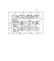
多くのパーソナルコンピュータ向けの図形配置に関するユーザ操作技術によれば、画像データを自由にレイアウトする場合には、画像を選択する操作と、選択した画像を配置する操作とが必要となる。図12はこうした操作のための表示の例を示す図である。図中、符号900は画像データを自由に配置して表示するアプリケーションの表示部,符号901は表示する画像を選択するために、複数の候補となる画像のアイコン902が表示されるアイコン表示部,符号903は表示画面上にレイアウトされた複数の表示画像,904は表示画像903あるいはアイコン902のうち、操作の対象であることを示すカーソル表示である。
According to a user operation technique related to graphic arrangement for many personal computers, when image data is laid out freely, an operation for selecting an image and an operation for arranging the selected image are required. FIG. 12 is a diagram showing an example of display for such operation. In the figure,
アイコン表示部901に示された画像の一つを選択し、表示部900の任意の位置にこれを配置しようとする場合、先ず、アイコン選択モードにおいて、アイコン表示部901にカーソルを移し、その中から表示しようとする画像のアイコン902にカーソルを移動する。次にアイコン902を選択するための決定操作を行ってアイコン移動モードに移行した後、カーソル表示904のついたアイコン902を任意の位置に移動して、レイアウト決定操作を行い、表示状態を決定する。即ち、表示すべき画像を選択するための操作と、表示位置を決定するための操作と、二つの操作に対してそれぞれカーソルを移動する操作が必要となる。
When one of the images displayed on the
こうした操作方法は、例えばマウスポインタやペン入力のように表示画面上を直接指定して、直接その位置に操作対象となるカーソルを移動することが可能な操作デバイスを用いた場合、比較的容易に実行することができる。 Such an operation method is relatively easy when an operation device that directly designates the display screen, such as a mouse pointer or a pen input, and can directly move the cursor to be operated to the position is used. Can be executed.
一方、テレビ受信装置あるいは家庭のリビングで使用されるAV機器の場合には、表示画面の前にマウスポインタやペン入力デバイスなどを操作するためのスペースがある環境にはない。そのため、手にもってボタンを操作する形のリモコンデバイスで操作することが一般的である。 On the other hand, in the case of a television receiver or an AV device used in a home living room, there is no environment in which there is a space for operating a mouse pointer, a pen input device, or the like in front of the display screen. Therefore, it is common to operate with a remote control device in which the buttons are operated by hand.
リモコンに設けられた方向ボタンによって、前述のカーソル移動操作を行おうとすると、例えば、図12にあるカーソル表示904をアイコン表示部901のなかで移動させる
場合には、一回のボタン操作によってアイコン一つ分の移動となる。そのため、アイコン表示部901の中で離れた位置にあるアイコン902を選択するためには多くのカーソル移動操作が必要となる。また、表示部900の中で、任意の位置に移動する際は、移動のステップごとのボタン操作が必要となる。従って、離れた位置の間を移動する操作は煩雑であり、いずれも、好適な操作系を構成することが困難となる。
For example, when the
その他に関連する公知技術として、特許文献3に開示されたものがある。
本発明の目的は、ディスプレイ上に画像をレイアウトする操作の操作性を向上することである。 An object of the present invention is to improve the operability of an operation for laying out an image on a display.
本発明は、上記課題を解決するために以下の手段を採用した。 The present invention employs the following means in order to solve the above problems.
本発明に係るプログラムは、画像記憶装置から第1の画像を取得するステップと、前記画像記憶装置から第2の画像を取得するステップと、前記画像記憶装置の移動を示す所定の情報を検出するステップと、前記第1の画像をディスプレイに表示するステップと、前記第2の画像を前記ディスプレイに表示するステップと、前記第1の画像及び前記第2の画像が前記ディスプレイに表示されている場合、前記画像記憶装置によって前記第2の画像が選択されることなく前記第1の画像が選択されたとき、前記所定の情報に応じて、前記ディスプレイに表示されている前記第1の画像の表示の位置が前記画像記憶装置の移動方向と一致する方向に移動するように前記第1の画像の表示の位置を制御するとともに、前記所定の情報に応じて、前記ディスプレイに表示されている前記第2の画像の表示の位置が前記画像記憶装置の移動方向と一致する方向に移動しないように制御するステップとをコンピュータに実行させるためのプログラムである。
また、本発明に係る表示制御装置は、画像記憶装置から第1の画像を取得し、前記画像記憶装置から第2の画像を取得する取得手段と、前記画像記憶装置の移動を示す所定の情報を検出する検出手段と、前記第1の画像をディスプレイに表示させ、前記第2の画像を前記ディスプレイに表示させる制御手段とを有し、前記第1の画像及び前記第2の画像が前記ディスプレイに表示されている場合、前記画像記憶装置によって前記第2の画像が選択されることなく前記第1の画像が選択されたとき、前記制御手段は、前記所定の情報に応じて、前記ディスプレイに表示されている前記第1の画像の表示の位置が前記画像記憶装置の移動方向と一致する方向に移動するように前記第1の画像の表示の位置を制御するとともに、前記所定の情報に応じて、前記ディスプレイに表示されている前記第2の画像の表示の位置が前記画像記憶装置の移動方向と一致する方向に移動しないように制御することを特徴とする。
A program according to the present invention detects a first image from an image storage device, a second image from the image storage device, and predetermined information indicating movement of the image storage device. A step of displaying the first image on a display; a step of displaying the second image on the display; and the first image and the second image being displayed on the display. , when the first image without the second image by said image storing device is selected is selected in response to the predetermined information, the display of the first image displayed on the display with the position of controlling the display position of the first image so as to move in a direction that coincides with the moving direction of the image storage device, in response to the predetermined information, the Display of the position of the second image displayed on Isupurei is a program for executing and controlling so as not to move in a direction that coincides with the moving direction of the image storage device in the computer.
Also, the display control device according to the present invention obtains a first image from the image storage device, obtaining means for obtaining a second image from the image storage device, a predetermined indicating the movement of the image storage device Detection means for detecting information, and control means for displaying the first image on a display and displaying the second image on the display, wherein the first image and the second image are If displayed on a display, when the first image is selected without the second image is selected by the image storage device, the control means, in response to the predetermined information, the display with indication of the position of the first image being displayed to control the display position of the first image so as to move in a direction that coincides with the moving direction of the image storage apparatus, the predetermined information Meet Te, and controls so that the display position of the second image displayed on the display does not move in a direction that coincides with the moving direction of the image storage device.
これにより、ディスプレイを見ながら、画像記憶装置のディスプレイに対する相対的な位置を変えつつ、選択画像を所望の領域に表示させていくことで、ディスプレイ上に画像をレイアウトできる。 Thus, the image can be laid out on the display by displaying the selected image in a desired region while changing the relative position of the image storage device to the display while looking at the display.
本発明によれば、ディスプレイ上に画像をレイアウトする操作の操作性が向上する。 According to the present invention, the operability of an operation for laying out an image on a display is improved.
以下に図面を参照して、この発明を実施するための最良の形態を、実施例に基づいて例示的に詳しく説明する。ただし、この実施例に記載されている構成部品の寸法、材質、形状、その相対配置などは、特に特定的な記載がない限りは、この発明の範囲をそれらのみに限定する趣旨のものではない。 The best mode for carrying out the present invention will be exemplarily described in detail below with reference to the drawings. However, the dimensions, materials, shapes, relative arrangements, and the like of the components described in this embodiment are not intended to limit the scope of the present invention only to those unless otherwise specified. .
図1〜図5を参照して、本発明の実施例1に係る画像表示方法について説明する。 With reference to FIGS. 1-5, the image display method which concerns on Example 1 of this invention is demonstrated.
本実施例においては、デジタルカメラと、デジタルカメラの撮影データを可視化して視聴する機能を有するデジタルテレビと、で構成される画像表示システムを用いた場合を例にして説明する。 In the present embodiment, a case where an image display system including a digital camera and a digital television having a function of visualizing and viewing photographing data of the digital camera is used will be described as an example.
図1は本発明の実施例1に係る画像表示方法に用いるデジタルテレビのブロック構成図
である。図中、符号101はチューナ部である。このチューナ部101には、図示しないデジタル放送の受信アンテナからの放送信号やCATVの放送信号が入力される。そして、チューナ部101は、後述する表示制御部111からの制御に基づいて受信信号から所定の伝送チャンネルを選択し、受信された伝送チャンネルの受信データに対する復調、誤り訂正などを実行してトランスポートストリーム(TS)信号を出力する。符号102はデマルチプレクサ部である。このデマルチプレクサ部102は、TS信号から番組配列情報を抽出して後述の表示制御部111に出力するとともに、表示制御部111の制御に従ってTS信号から目的の映像信号、音声信号、データ放送データを分離する。音声信号は映像・音声デコーダ部103でデコードされ、DA変換を含む音声出力部104から音声として出力される。映像信号は、映像・音声デコーダ部103でデコードされ、一旦ビデオメモリ107に書き込まれた後、映像合成部108を通じて表示器113に表示される。表示器113を構成するデバイスは、例えば液晶ディスプレイ、プラズマディスプレイを含むマトリクス電極構造を持つフラットパネルや、ブラウン管によるCRTなどである。分離されたデータ放送信号は記憶部112へ格納され、データ放送の視聴時に表示制御部111へ出力するために読み出される。
FIG. 1 is a block diagram of a digital television used for an image display method according to
符号110は操作入力部である。この操作入力部110は、赤外線信号を利用したリモコンの受信部やデジタルテレビ100に直接設けられた操作スイッチを含み、ユーザの操作を入力して表示制御部111に送る。表示制御部111は、操作入力部107から受信するユーザの操作入力、デマルチプレクサ部102から受信する番組配列情報、あるいは記憶部112から読み出したデータ放送データが入力されて、次の制御を行う。すなわち、表示制御部111は、これらの入力データに基づいて、ユーザに提示するグラフィックデータをビデオメモリ107に書き込み、映像・音声デコーダ部103による映像信号と、後述のデジタルカメラ撮影の静止画像信号を映像合成部108において適宜合成し、表示器113に表示させる。デジタルテレビ100は、以上の構成要素において表示制御部111の統合的な制御動作によってユーザの操作に基づきデジタル放送を受信することにより、目的とする放送番組を視聴することを可能とする。
また、デジタルテレビ100において、符号105はメモリカード入出力部である。このメモリカード入出力部105は、あとで説明するデジタルカメラ200で撮影した画像データを格納した着脱型メモリカードとの接続により、撮影された画像データと付加情報を含む画像データの入出力を行う。また、メモリカード入出力部105は、読み込んだデータを記憶部112に画像ファイルとして格納する。表示制御部111は予め格納されたプログラムに基づいてグラフィカルユーザインタフェースとなる表示をビデオメモリに出力して表示器113に表示する。更に、表示制御部111は、操作入力部110を通じて入力されるユーザ操作に従い、メモリカードから読み込んだ画像データまたは記憶部112に格納された画像ファイルを読み出して画像データを画像処理部106に送る。画像処理部106では画像データのデコードが行われ、ビデオメモリ107を介して、映像合成部108において操作のためのグラフィックと合成される。そして、合成された画像が表示器113に表示される。
In the
また、符号109は無線入出力部である。この無線入出力部109は、後で説明するデジタルカメラ200の無線入出力部208と通信し、制御データおよび画像ファイルの伝送を行う。受信したデジタルカメラの撮影画像ファイルデータはメモリカード入出力部105から入力された画像データと同様に画像ファイルとして記憶部112に格納される。また、デジタルカメラの撮影画像ファイルデータに基づく画像は、画像処理部106を通じて表示器113に表示される。無線通信の手段には、IEEE802.11bによる無線LAN、Bluetooth(R)による近距離無線などが使用される。
デジタルテレビ100においては、以上の構成要素において表示制御部111の統合的
な制御動作によって、ユーザの操作に基づきデジタルカメラ200で撮影した画像を視聴することが可能となる。
In the
図2は本発明の実施例1に係る画像表示方法に用いるデジタルカメラのブロック構成図である。図中、符号201は、レンズ、絞り、などの光学系と撮像素子、素子駆動回路などを含み、画像を電子的に撮影して非圧縮画像データを出力するデジタルカメラの撮像部である。符号202は非圧縮の画像データを圧縮し、また、記録メディアから後述のメモリカード入出力部206から読み出された圧縮画像データを伸張すると同時に表示部203に表示するための画像データ信号を出力する圧縮伸張部である。符号206はメモリカード入出力部である。このメモリカード入出力部206は、圧縮された画像データに必要な付加データを加えて画像ファイルを構成して、これを記録メディアであるメモリカード209に格納する。また、メモリカード入出力部206は、記録メディアから画像ファイルを読み出し表示部203で表示するための圧縮画像データや必要な情報を取り出す。表示部203は、例えば、液晶ディスプレイ(LCD)で構成される。液晶ディスプレイに代えて、有機ELディスプレイやその他の平面ディスプレイを用いることもできる。
FIG. 2 is a block diagram of a digital camera used in the image display method according to the first embodiment of the present invention. In the figure,
符号208は無線入出力部である。この無線入出力部208は、デジタルテレビ100の無線入出力部109と通信して、画像データおよび制御情報を送信する。画像データは、デジタルカメラ200で撮影されてメモリカード209に格納された画像ファイルから制御部205によって読み出され、無線入出力部208に供給される。また、制御データは、操作入力部204及び位置検出部207から出力される情報に基づき制御部205によって生成されるデータである。無線通信の手段には、IEEE802.11bによる無線LAN、Bluetooth(R)による近距離無線などが使用されることはデジタルテレビの無線入出力部109で述べたとおりである。
符号207は位置検出部である。この位置検出部207は、ユーザがデジタルカメラ200本体を上下左右または前後に動かしたり、傾けたりすることでデジタルカメラ200に対する操作入力を行うものである。本実施例においては、位置検出部にXYZ三軸の加速度センサを用い、加速度センサ出力信号に応じて移動の方向、時間あたりの移動量、回転角度を出力する。
符号204は撮影のトリガーとなるシャッターボタンや表示画像を選択し決定するための方向/決定ボタンを始め、ユーザのデジタルカメラ200への操作を入力する操作入力部である。
図3は本発明の実施例1に係るデジタルカメラの外観図である。なお、図3においては、上方から見た外観図(上)と裏面から見た外観図(下)を示している。この図は、上記図2を参照して説明した操作入力部204を構成するボタンなどの要素を説明するものである。図中、符号221は電源ボタンである。この電源ボタン221は、デジタルカメラ200の電源の投入および遮断を操作する。符号222はシャッターボタンである。このシャッターボタン222の全押しによって撮影時の撮像動作にトリガー操作を与えるとともに、ボタンの半押しによって撮影直前に撮影のためのフォーカス動作を開始させ、撮影条件に関する表示を開始させる操作を行うボタンである。符号223はズームボタンであり、これにより撮影時のズーム操作を行う。また、このズームボタン223は、撮影画像の視聴時においては表示画像の拡大、縮小の操作を行うために用いられる。符号224はファインダーであり、図示しない撮像部のレンズを通して撮影範囲の確認を行うものである。符号225はデジタルカメラ200の動作モードを切り替えるスイッチである。このスイッチ225により、撮像部201によって画像を撮影する撮影モード、メモリカード209に格納された撮影画像を液晶モニタ226に表示して視聴する再生モード、メモリカード209に格納された撮影画像をデジタルテレビ100の表示器113で表示して視
聴するテレビ視聴モード、のいずれかを選択することができる。符号227は表示部203に表示される操作に関するグラフィックデータ上のフォーカスを移動して操作項目を選択し決定する操作を行うための方向ボタン及び決定ボタンである。また、符号226は表示部203を構成する液晶モニタであり、228はその他の操作ボタンである。
FIG. 3 is an external view of the digital camera according to
図2中、符号205は、これまで説明したデジタルカメラ200の構成要素を有機的に制御して、デジタルカメラの機能をユーザに提供する制御部である。制御部205は、ユーザがデジタルカメラ200を目的の撮影に適した状態に設定するためのグラフィック要素を表示部203に表示するとともに、操作入力部204を介して入力されるユーザ操作に基づいてデジタルカメラ200の各部の動作条件を制御する。デジタルカメラ200が撮影モードに設定されたとき、被写体に向けられた撮像部201への画像の入力状態を、逐次圧縮伸張部202を通じて表示部203に表示する。そのため、表示部203はファインダーとして機能する。また、制御部205は、ユーザが目的の撮影条件が整ったと判断した瞬間に操作入力部204のシャッターボタンを押すと、設定に応じて図示しないストロボ手段の発光を制御し、そのタイミングで撮像部201において撮影された画像データを圧縮伸張部202で圧縮する。更に、制御部205は、図示しないカレンダ時計から現在の日付時刻データを獲得し、デジタルカメラの情報及び撮影条件に関する情報とともに付加情報として画像ファイルを構成する。そして、制御部205は、当該画像ファイルを、メモリカード入出力部206を介してメモリカード209に格納する。
In FIG. 2,
また、制御部205は、デジタルカメラ200が再生モードに設定されたとき、メモリカード入出力部206を介してメモリカード209に格納された画像データから撮影画像データを読出し、圧縮伸張部202を介して表示部203に表示する。操作入力部204の左右の方向ボタン操作により、表示対象となる画像が順次変更される、また、操作入力部204のズームボタンの操作により、表示される画像が拡大、または縮小される。拡大表示状態にあるとき、操作入力部204の上下左右の方向ボタン操作により、画像データ内の表示領域を移動することができる。
In addition, when the
デジタルカメラ200がテレビ視聴モードにあるとき、制御部205の動作により、またデジタルテレビ100の表示制御部111と連携して動作することによって、撮影画像を本システムのデジタルテレビ100の表示器113に表示して視聴することが出来る。
When the
図4は本発明の実施例1に係る画像表示方法の手順を示すフローチャート図である。この図においては、テレビ視聴モードにおけるデジタルカメラ200とデジタルテレビ100の動作を制御データ、画像データのフローを中心に説明する図である。
FIG. 4 is a flowchart showing the procedure of the image display method according to the first embodiment of the present invention. In this figure, the operations of the
テレビ視聴モードは、ユーザのデジタルカメラ200への動作モード切替操作で開始される(S101)。動作モードスイッチ225の操作を検出した制御部205はデジタルカメラ200の無線入出力部208とデジタルテレビ100の無線入出力部109を通じ、動作モードがテレビ視聴モードに設定された旨の動作モード情報通知をデジタルテレビ100の表示制御部111へ通知する(S102〜S104)。デジタルカメラ200の制御部205は、続いてメモリカード209に格納され表示の対象となる画像データをデジタルテレビ100に送信するよう制御する(S105)。画像データはメモリカード209から無線を通じてデジタルテレビ100の記憶部112に転送され、格納される(S106〜S108)。
The TV viewing mode is started by an operation mode switching operation to the
動作モードをテレビ視聴モードに設定したユーザは、デジタルテレビ100に表示して視聴しようとする画像をデジタルテレビ100の液晶モニタを用いて選択する。即ち、デジタルカメラ200の左右の方向ボタン227を操作すると、操作入力部204の出力(S109、S112)が制御部205で検出される。そして、制御部205は対象となる
画像データをメモリカードから読み出して表示部203で表示するよう制御する(S110、S113およびS111、S114)。
The user who has set the operation mode to the television viewing mode selects an image to be displayed and viewed on the
ユーザは表示しようとする画像を見つけると、デジタルカメラ200をデジタルテレビ100に向けてシャッターボタン222を半押しする。仮表示操作としての操作入力部204の出力は制御部205で検出される(S115)。そして、無線を通じてデジタルテレビ100の表示制御部111に、選択された画像を指定する情報と仮選択操作が行われたことが通知される(S116〜S118)。表示制御部111は指定された画像の画像データを記憶部112から読出し、画像処理部106を通じて表示器113に表示されるよう制御する(S119〜S120)。ここで、画像が表示器113に表示されるとは、画像が表示器113上の一部の領域に表示されること、すなわち、表示器113の表示領域の外周内における一部の領域に画像が表示されることをいう。
When the user finds an image to be displayed, the user points the
デジタルテレビ100の表示器113に目的の画像が表示された状態で、ユーザがデジタルカメラ200の本体を上下および左右に移動させることにより、表示器113に表示された画像の表示位置を調整することができる。即ち、デジタルカメラ本体の位置検出部207で検出されるデジタルカメラ200の移動量に基づき制御部205から位置情報が無線を通じてデジタルテレビ100の表示制御部111に通知される(S121〜S124)。表示制御部111は通知された位置情報をもとに、ビデオメモリ107及び映像合成部108を制御して表示器113上に表示される画像データの表示位置を制御する(S125)。位置情報の通知はデジタルカメラ200の移動検出ごと、または一定時間ごとに繰り返し行われ(S126〜S130及びS131〜S135)、ユーザは表示器113上の所望の表示位置に画像を移動させることができる。
While the target image is displayed on the
ユーザが半押し状態に操作していたシャッターボタン222を全押しすることにより、表示器113上の画像の表示位置を決定することできる。即ち、シャッターボタン222の全押しを、制御部205が検出した場合(S136)、無線を通じ表示位置決定通知をデジタルテレビ100の表示制御部111に通知する(S137〜S139)。表示制御部111はこの通知に基づき、ビデオメモリ107及び映像合成部108を制御して表示器113上に表示される画像データの表示位置を決定する(S140)。
The display position of the image on the
図5は本発明の実施例1に係る画像表示方法の具体的手順の説明図である。すなわち、図5は上述したデジタルカメラ本体の移動と表示器113上の画像表示位置の変化を説明する図である。図5(a)はデジタルテレビ100とデジタルカメラ200の位置関係を示す図である。この図においては、デジタルカメラ200をデジタルテレビ100の表示面に対向した位置で上下左右、あるいは回転方向に移動させると、デジタルテレビ100の表示器113に表示された画像の表示位置も同じ方向に移動することを示している。また、デジタルカメラ200の左右ボタンによって液晶モニタ上で表示対象となる画像を選択することができ(同図(b))、シャッターボタン222の半押しによってデジタルテレビ100の表示器113に選択した画像(図では画像B)を表示させることができ(同図(c))、デジタルカメラ200の移動によって選択画像の表示位置を移動させることができる(同図(d))。また、デジタルカメラ200の回転によって表示方向を回転させることができ(同図(e))、デジタルテレビ100に近づける動作によって他の画像との重なり関係をより下側になるようにすることができる(同図(f))。つまり、重なった領域部分においていずれの画像を表示させるかを選ぶことができる。更に、シャッターの全押しによって表示状態の決定を行うことができる(同図(g))。図5において、選択して位置調整の対象となった画像(図の画像B)には、表示された画像の周囲を着色し、操作対象であることを示している。こうしたフォーカス表示は表示状態を決定した時点で終了する(同図(g))。図5においては、他の画像(図の画像A)との重なり関係をより下側に変更する動作を示したが、デジタルカメラ200をデジタルテレビ100か
ら遠ざける動作によって、より上に重なるように変更することも可能である。
FIG. 5 is an explanatory diagram of a specific procedure of the image display method according to the first embodiment of the present invention. That is, FIG. 5 is a diagram for explaining the movement of the digital camera main body and the change in the image display position on the
図4に戻り、デジタルカメラ200において、既にデジタルテレビ100に表示された画像を選択した場合の動作について説明する。図において、ユーザの操作入力によってデジタルカメラ上の液晶モニタ上で画像が選択され(S151〜S157)、制御部205から無線を介してデジタルテレビ100の表示制御部111に選択画像の指定情報および仮選択操作が通知される。このとき、指定された画像がデジタルテレビ100の表示器113において既に表示されている画像であった場合には、表示制御部111は既に表示されている画像を表示位置制御の対象とする(S161〜S163)。そして、その後通知されるデジタルカメラ200の位置情報によって、指定された画像の既に決定された位置を移動して表示する(S164〜S178)。
Returning to FIG. 4, the operation when the
デジタルカメラ200の位置に応じて画像の表示位置を移動する仮選択表示状態において、ユーザがデジタルカメラ200のズームボタン223を操作した場合、操作入力部204の出力(S179)を検出した制御部205は、無線を介してデジタルテレビの表示制御部111へズーム操作を表示制御情報として通知する(S180〜S182)。表示制御部111は画像処理部106を通じて表示する画像の拡大、または縮小画像を作成し、ビデオメモリ107、映像合成部108を介して表示器113に拡大、または縮小画像を表示させる(S183〜S184)。このとき、デジタルカメラ200の制御部205は液晶モニタにも同様の拡大、または縮小画像を表示させる。
When the user operates the
また、拡大縮小操作中にユーザが方向ボタン227を操作した場合、同様の経路を通じて表示制御部111に表示制御情報を通知する(S185〜S188)。表示制御部111では、拡大,縮小表示の中心位置を調整し、表示器113に表示する画像中の表示領域を変更する(S189〜S190)。ユーザがデジタルカメラ200のシャッターボタン222を全押しする操作によって、こうした表示状態が決定され、デジタルテレビ100の表示器113上の表示状態が固定される(S191〜S195)ことは、すでに説明した通りである。
When the user operates the
以上説明したとおり、本実施例のシステムにおいては、複数の撮影した画像を格納しているデジタルカメラにおいて表示の対象となる画像を選択し、画像を表示するデジタルテレビの表示器上で、デジタルカメラとデジタルテレビとの相対位置に応じた位置に選択した画像を表示するステップと、さらにデジタルカメラ上で選択した別の画像をデジタルカメラとデジタルテレビの他の相対位置に表示するステップと、を有する。これにより、デジタルテレビの表示画面上で表示の対象となる画像を選択するための操作が不要となる。従って、リビングなどに設置され机など平面スペースがなく、マウスやペン入力など直接平面内の位置を指定できる入力デバイスが使用できない操作環境においても、簡便な操作による複数の画像のレイアウトを実現することができる。 As described above, in the system of the present embodiment, the digital camera that selects the image to be displayed in the digital camera storing a plurality of captured images and displays the image on the digital camera is displayed. Displaying the selected image at a position corresponding to the relative position between the digital camera and the digital camera, and further displaying another image selected on the digital camera at another relative position of the digital camera and the digital TV. . Thereby, an operation for selecting an image to be displayed on the display screen of the digital television becomes unnecessary. Therefore, even in an operating environment where there is no plane space such as a desk installed in a living room and an input device that can directly specify the position in the plane, such as a mouse or pen input, cannot be used, multiple image layouts can be realized by simple operation. Can do.
また、画像データを選択して液晶モニタに表示させたデジタルカメラ本体を、直接移動することで、デジタルテレビの表示器上の画像位置を移動させることができる。従って、あたかも掌中にある複数の写真カードの束から目的の写真カードを一番表に移し、この写真カードの束を直接動かして表示したい場所に置くことができるかのような操作が可能となり、現実の模倣による直感的で判りやすい操作をすることができる。 Further, by directly moving the digital camera main body that has been selected and displayed on the liquid crystal monitor, the image position on the display device of the digital television can be moved. Therefore, it becomes possible to move the target photo card from the bundle of multiple photo cards in the palm to the top, and move the photo card bundle directly to place it where you want to display it. It is possible to perform intuitive and easy-to-understand operations by imitating reality.
本実施例の説明においては、デジタルカメラのメモリカードに格納された画像データを、操作の開始時に一括して転送し、デジタルカメラ上の画像選択時には選択情報のみを通知するとして説明した。これは、画像の選択からデジタルテレビ上への画像表示までに要する時間を短縮するために採用した構成である。ただし、画像データの転送が充分な性能であれば、ユーザ操作による画像の選択の度に画像データを転送する構成を採用すること
も可能である。
In the description of the present embodiment, the image data stored in the memory card of the digital camera is transferred collectively at the start of the operation, and only selection information is notified when an image on the digital camera is selected. This is a configuration adopted to shorten the time required from image selection to image display on a digital television. However, it is also possible to adopt a configuration in which image data is transferred each time an image is selected by a user operation if the image data transfer has sufficient performance.
また、画像データの一括転送の方法は、表示対象となる複数の画像データを格納したメモリカードなどのリムーバブルメディアを、操作の開始時、あるいはそれ以前に予めデジタルカメラからデジタルテレビに移して接続してもよい。また、無線による一括転送であって、デジタルカメラとデジタルテレビとが無線を通じてお互いを認識した時点で、動作モードがテレビ視聴モードに操作される前に画像データを予め転送し、デジタルテレビの記憶部に格納してもよい。 Also, the batch transfer method of image data is to connect a removable medium such as a memory card that stores a plurality of image data to be displayed by moving it from the digital camera to the digital TV in advance or before starting the operation. May be. In addition, when the digital camera and the digital TV recognize each other wirelessly, the image data is transferred in advance before the operation mode is changed to the TV viewing mode, and the storage unit of the digital TV. May be stored.
また、無線通信には赤外線を用いた方法も利用することができる。ただし画像データの転送に時間を要するため、予め画像データを転送する手段や、メモリカードによって予め画像データを移動するなどの手段と併用するとより効果的である。また、デジタルカメラの移動を妨げない範囲においてであれば、有線による接続を用いた通信であっても本発明の趣旨を損なうものではない。 A method using infrared rays can also be used for wireless communication. However, since it takes time to transfer image data, it is more effective when used together with a means for transferring image data in advance or a means for moving image data in advance using a memory card. Further, as long as the movement of the digital camera is not hindered, communication using a wired connection does not impair the gist of the present invention.
図6〜図11を参照して、本発明の実施例2に係る画像表示方法について説明する。 With reference to FIGS. 6-11, the image display method which concerns on Example 2 of this invention is demonstrated.
本実施例においては、デジタルカメラとデジタルビデオカメラを接続し、デジタルカメラの撮影画像を可視化して視聴する機能を有するデジタルテレビ同士をネットワークで接続し、デジタルカメラの撮影画像の視聴を共有するシステムを用いた場合を例にして説明する。 In this embodiment, a system for connecting a digital camera and a digital video camera, connecting digital TVs having a function of visualizing and viewing a captured image of the digital camera via a network, and sharing viewing of the captured image of the digital camera A description will be given taking the case of using as an example.
図6は本発明の実施例2に係る画像表示方法に用いるシステム全体の構成図である。図6において、符号301は、アンテナ302を通じて放送波を受信しテレビ番組を視聴するデジタルテレビ(1)である。デジタルテレビ(1)301は、無線通信手段で接続されたデジタルカメラ(1)304からの撮影画像データを受信し、これを表示する機能を有する。また、デジタルテレビ(1)301は、デジタルビデオインタフェースを通じて接続されたデジタルビデオカメラ(1)303が撮影するユーザの様子を撮影した映像データとデジタルカメラ(1)304の撮影画像データを、接続されたネットワーク320(インターネット)に送信する機能を持つ。ネットワーク320には、同様のデジタルテレビ(2)311が接続され、デジタルテレビ(2)311は受信した映像データおよび画像データを表示する。このように、デジタルテレビ(2)311は、そのユーザに対して、デジタルテレビ(1)301のユーザとともにデジタルカメラ(1)304の撮影画像の視聴を共有させる機能を持つ。
FIG. 6 is a configuration diagram of the entire system used in the image display method according to the second embodiment of the present invention. In FIG. 6,
デジタルテレビ(2)311はデジタルテレビ(1)301同様の構成を有している。すなわち、デジタルテレビ(2)311はアンテナ312を通じて放送波を受信してテレビ番組視聴を行わせる機能と、無線接続されたデジタルカメラ(2)314の撮影画像データを受信して視聴させる機能と、デジタルビデオインタフェースを通じて接続されたデジタルビデオカメラ(2)313が撮影するユーザの様子を撮影した映像データとデジタルカメラ(2)314の撮影画像データをネットワーク320に送信する機能を有する。一方、デジタルテレビ(1)301は、受信したこれらの映像データおよび画像データを表示させ、その視聴をデジタルテレビ(2)311のユーザと共有させる機能を持つ。
The digital television (2) 311 has the same configuration as the digital television (1) 301. That is, the digital television (2) 311 has a function of receiving broadcast waves through the
図7は本発明の実施例2に係る画像表示方法に用いるデジタルテレビのブロック構成図である。図中、符号321はチューナ部である。このチューナ部321には、デジタルテレビ放送の受信アンテナ(図10に示したアンテナ302)からの放送信号やCATVの放送信号が入力される。そして、チューナ部321は、後述する制御部330からの制御に基づいて受信信号から所定の伝送チャンネルを選択し、受信された伝送チャンネルの受
信データに対する復調、誤り訂正などを実行しトランスポートストリーム(TS)信号を出力する。符号322はデマルチプレクサ部であり、TS信号から番組配列情報を抽出して後述の制御部330に出力するとともに、制御部330の制御に従ってTS信号から目的の映像信号、音声信号、データ放送データを分離する。音声信号は映像・音声デコーダ部323でデコードされ、DA変換を含む音声出力部324から音声として出力される。映像信号は映像・音声デコーダ部323でデコードされ、映像合成部327に含まれるビデオメモリに書き込まれた後、映像合成部327を通じて表示部329に表示される。表示部329を構成するデバイスは、例えば液晶ディスプレイ、プラズマディスプレイを含むマトリクス電極構造を持つフラットパネルや、ブラウン管によるCRTなどである。
FIG. 7 is a block diagram of a digital television used in the image display method according to the second embodiment of the present invention. In the figure,
分離されたデータ放送信号は記憶部331へ格納され、データ放送の視聴時に制御部330に再び読み出される。
The separated data broadcast signal is stored in the
符号332は操作入力部である。この操作入力部332は、赤外線信号を利用したリモコンの受信部やデジタルテレビ(1)301に直接設けられた操作スイッチを含み、ユーザの操作を入力して制御部330に送る。制御部330は操作入力部332から受信するユーザの操作入力、デマルチプレクサ部322から受信する番組配列情報、あるいは記憶部331から読み出したデータ放送データが入力されて、次の制御を行う。すなわち、制御部330は、これらの入力データに基づいて、ユーザに提示するグラフィック信号を映像合成部327に含まれるビデオメモリに書き込み、映像・音声デコーダ部323による映像信号と、後述のデジタルカメラ撮影の静止画像信号を合成し、表示部329に表示させる。デジタルテレビ(1)301は、以上の構成要素において制御部330の統合的な制御動作によって、ユーザの操作に基づきデジタル放送を受信することにより、目的とする放送番組を視聴することを可能とする。
また、デジタルテレビ(1)301において、符号333はメモリカード入出力部である。このメモリカード入出力部333は、あとで説明するデジタルカメラ(1)304で撮影した画像データを格納した着脱型メモリカードとの接続により、撮影された画像データと付加情報を含む画像データの入出力を行う。また、メモリカード入出力部333は読み込んだデータを記憶部331に画像ファイルとして格納する。制御部330は予め格納されたプログラムに基づいてグラフィカルユーザインタフェースとなる表示をビデオメモリに出力して表示部329に表示する。更に、制御部330は操作入力部332を通じて入力されるユーザ操作に従い、メモリカードから読み込んだ画像データまたは記憶部331に格納された画像ファイルを読み出して画像データを静止画デコーダ部326に送る。静止画デコーダ部326では圧縮符号化された画像データのデコードが行われ、画像処理部328により必要に応じて縮小拡大処理が施された後、映像合成部327において操作のためのグラフィックと合成される。そして、合成された画像が表示部329に表示される。
In the digital television (1) 301,
また、符号334は無線入出力部である。この無線入出力部334は、後で説明するデジタルカメラ(2)314の無線入出力部208と通信し、制御データおよび画像ファイルの伝送を行う。受信したデジタルカメラの撮影画像ファイルデータはメモリカード入出力部333から入力された画像データと同様に画像ファイルとして記憶部331に格納され、同様の信号処理を通じて表示部329に表示される。無線通信の手段には、IEEE802.11bによる無線LAN、Bluetooth(R)による近距離無線などが使用される。
デジタルテレビ(1)301においては、以上の構成要素において制御部330の統合的な制御動作によって、ユーザの操作に基づきデジタルカメラで撮影した画像を視聴することが可能となる。
In the digital television (1) 301, it is possible to view an image captured by a digital camera based on a user operation by the integrated control operation of the
また、符号335はデジタルビデオインタフェース部である。このデジタルビデオインタフェース部335は、デジタルビデオカメラ(1)303との接続により、デジタルビデオカメラ(1)303の制御のための通信、およびデジタルビデオデータの通信を行う。制御部330はユーザに提示するグラフィックによるデジタルビデオカメラ(1)303の操作パネルを表示部329に表示する。そして、ユーザはリモコンによって操作パネル上のグラフィック要素を操作することによって、デジタルビデオカメラ(1)303を操作することができる。即ち、制御部330は操作パネルの表示に対して操作入力部332を通じて入力されるユーザの操作入力に基づき、デジタルビデオカメラ(1)303の制御コマンドを生成し、これを、デジタルビデオインタフェース部335を通じてデジタルビデオカメラ(1)303へ送信する。デジタルビデオカメラ(1)303はこのコマンドに応じて記録されたビデオ映像データ、またはビデオカメラで撮影されたビデオ映像データを送信する。そして、デジタルビデオインタフェース部335を通じて受信されたビデオ映像データは、映像・音声デコーダに送られ音声出力部324および表示部329を通じて映像と音声が再生される。
デジタルビデオカメラ(1)303の接続には、例えばIEEE1394に定める高速シリアル通信を用いることが出来る。デジタルビデオカメラ(1)303は、例えば1394 Trade Associationが定めるAV/C Camera Subunit SpecificationおよびAV/C Tape Recorder/Player Subunit Specificationに基づくコマンドセットによって制御され、IEC61883 Consumer audio/video equipment−Digital interfaceに従って映像信号を転送する。 For connection of the digital video camera (1) 303, for example, high-speed serial communication defined in IEEE1394 can be used. The digital video camera (1) 303 is controlled by a command set based on, for example, AV / C Camera Subspecifcation specified by 1394 Trade Association and AV / C Tape Recorder / Player Subspecimen Specified Specified IEC61883 Transfer the signal.
以上の構成要素において制御部330の統合的な制御動作によって、ユーザの操作に基づきデジタルビデオカメラによる映像および音声をデジタルテレビ(1)301で視聴することが可能となる。
Through the integrated control operation of the
図8は本発明の実施例2に係る画像表示方法に用いるデジタルカメラのブロック構成図である。デジタルカメラ(1)304においては、上記実施例1におけるデジタルカメラ200とほぼ同様の構成を持ち、同様の動作を行う。図8において上記実施例1で説明したデジタルカメラ200と同一の構成であり、かつ同一の機能(動作)行う部材には同一の符号を付与して、その説明は省略する。デジタルカメラ200との相違は、位置検出部を持たない点にある。従って、制御部305は位置検出部の制御機能を持たず、デジタルカメラ(1)304の位置変化に関する通信をデジタルテレビ304と行わない点において、実施例1におけるデジタルカメラ200の制御部205と異なっている。
FIG. 8 is a block diagram of a digital camera used in the image display method according to the second embodiment of the present invention. The digital camera (1) 304 has substantially the same configuration as the
以上、デジタルテレビ(1)301とデジタルカメラ(1)304について説明した。ここで、デジタルテレビ(2)311はデジタルテレビ(1)301と同一の構成を持ち、同様の動作を行うものである。また、デジタルカメラ(2)314はデジタルカメラ301と同一の構成を持ち、同様の動作を行うものである。従って、これらの説明は省略する。デジタルテレビ(1)301およびデジタルテレビ(2)311は、放送番組を視聴する動作、デジタルカメラの画像を視聴する動作、デジタルビデオカメラの映像を視聴する動作に加え、ネットワークを通じて相互に接続し、双方のユーザの姿を互いに相手のデジタルテレビに示し、デジタルカメラの画像視聴を共有する動作を行うことができる。本実施例においては、この動作を同期視聴動作と呼ぶ。
The digital television (1) 301 and the digital camera (1) 304 have been described above. Here, the digital television (2) 311 has the same configuration as the digital television (1) 301, and performs the same operation. The digital camera (2) 314 has the same configuration as the
デジタルカメラ304の構成は、上記実施例1で図3に示すデジタルカメラ200と基本的に同一であるので、同一の構成部分に同一の符号を付して、その説明は省略する。
Since the configuration of the
図9は本発明の実施例2に係る画像表示方法の手順を示すフローチャート図である。この図は本実施例のシステムにおける同期視聴動作について、デジタルテレビ(1)および(2)、デジタルカメラ(1)および(2)、デジタルビデオカメラ(1)および(2)の間の制御データ、画像データ、映像データのフローを中心に説明する図である。 FIG. 9 is a flowchart showing the procedure of the image display method according to the second embodiment of the present invention. This figure shows the control data between the digital televisions (1) and (2), the digital cameras (1) and (2), and the digital video cameras (1) and (2) with respect to the synchronous viewing operation in the system of the present embodiment. It is a figure explaining focusing on the flow of image data and video data.
デジタルテレビの同期視聴動作はデジタルカメラへの動作モード切替操作で開始される。デジタルテレビ(1)301のユーザ(1)がデジタルカメラ(1)304のスイッチ225をテレビ視聴モードに設定する(S200)。これをデジタルカメラ(1)304が検出すると、デジタルカメラ(1)304は無線を通じデジタルテレビ(1)301へ通知する(S201)。デジタルテレビ(1)301では通知を受けた制御部330がネットワークインターフェース部338を介し、ネットワーク320を通じて動作モード情報としてデジタルテレビ(2)311へ通知する(S202)。この通知を受けたデジタルテレビ(2)311ではデジタルビデオインタフェース部を通じてデジタルビデオカメラ(2)313へコマンドによるビデオ制御信号を送り(S202)、デジタルビデオカメラ(2)313に撮影したビデオ映像信号を出力させる(S203)。これを受信したデジタルテレビ(2)311は、ネットワーク220を通じてデジタルテレビ(1)301へビデオ映像信号を転送する。そして、デジタルテレビ(1)301ではネットワークインターフェース部338でこれを受信する。そして、受信したビデオ映像信号はデマルチプレクサを介し映像・音声デコーダ部へ送られ、音声出力部324と表示部329で出力される。即ち、デジタルテレビ(2)311のユーザ(2)の様子を撮影した映像データがデジタルテレビ(1)301へ送信され、表示される。
Synchronous viewing operation of a digital television is started by an operation mode switching operation to the digital camera. The user (1) of the digital television (1) 301 sets the
デジタルテレビ(1)301では、ユーザ(2)のビデオ映像の表示を開始するとともに、デジタルビデオカメラ(1)303へデジタルビデオインタフェースを通じてコマンドによるビデオ制御信号を送り(S205)、デジタルビデオカメラ(1)303で撮影したビデオ映像信号を出力させる(S206)。これを受信したデジタルテレビ(1)301は、ネットワーク220を通じてデジタルテレビ(2)311へビデオ映像信号を転送する(S207)。そして、デジタルテレビ(2)311ではデジタルテレビ(1)301と同様の動作によってビデオ映像の出力を行う。即ち、デジタルテレビ(1)301のユーザ(1)の様子を撮影した映像データがデジタルテレビ(2)311へ送信され、表示される。こうしてユーザ(1)とユーザ(2)は、デジタルテレビ(1)301とデジタルテレビ(2)311によってお互いの姿を映像で見ながら会話を行う、所謂テレビ会議のような状況を開始することができる。
The digital television (1) 301 starts displaying the video image of the user (2) and sends a video control signal by a command to the digital video camera (1) 303 through the digital video interface (S205). The video image signal photographed in
次に、ユーザ(1)は、手元のデジタルカメラ(1)304の液晶モニタを用いて視聴しようとする画像を選択する。即ち、デジタルカメラ(1)304の左右の方向ボタン227を操作し、液晶モニタに表示される画像を順に変更する(S208〜S209)。ユーザ(1)は表示しようとする画像を見つけるとデジタルカメラ(1)304をデジタルテレビ(1)301に向けて、デジタルカメラ(1)304のシャッターボタン222を半押しする。デジタルカメラ(1)304では検出された操作をデジタルテレビ(1)301に通知する(S211)とともに、該当する画像の画像データをデジタルテレビ(1)301へ無線を通じて送信する(S213)。デジタルテレビ(1)301では、デジタルテレビ(2)311に対しネットワークを通じて仮選択された画像に関する情報を通知する(S212)とともに、受信した画像データを送信する(S214)。デジタルテレビ(2)311においては、ネットワークインターフェース部338で受信した画像データを一旦記憶部331に格納する。
Next, the user (1) selects an image to be viewed using the liquid crystal monitor of the digital camera (1) 304 at hand. That is, the left and
デジタルカメラ(1)304から仮選択の通知を受けったデジタルテレビ(1)301においては、制御部330の制御において仮選択送信動作を行う。即ち、デジタルビデオカメラ(1)303から入力される映像データの中からデジタルカメラ(1)304の位
置(デジタルテレビ(1)301に対する位置)を検出し、位置情報としてデジタルテレビ(2)311へ通知する。
In the digital television (1) 301 that has received the provisional selection notification from the digital camera (1) 304, a provisional selection transmission operation is performed under the control of the
映像データからデジタルカメラ(1)304の位置情報を抽出する機能は、デジタルテレビ(1)301の画像パターン検出部336で行われる。画像パターン検出部336はデジタルビデオインタフェース部335で受信されるデジタル映像データをデコードし、フレームごとの映像のなかから予め登録されたデジタルカメラ(1)304の外観を示す画像パターンを検出し、フレーム平面内の位置情報および傾き情報として制御部330に通知する。制御部330は他の操作入力を加味しつつ、ネットワークインターフェース部338を通じ、位置情報通知としてデジタルテレビ(2)311へ送信する。
The function of extracting the position information of the digital camera (1) 304 from the video data is performed by the image
仮選択の通知を受け取ったデジタルテレビ(2)311においては、制御部330の制御において仮選択受信動作を行う。即ちデジタルテレビ(1)301から受信した画像データを、継続して受信する位置情報通知に基づいてデジタルテレビ(1)301から受信する映像データに重畳して表示する。
In the digital television (2) 311 that has received the notification of provisional selection, provisional selection reception operation is performed under the control of the
仮選択受信操作においてデジタルテレビ(2)311の制御部330は、ネットワークを通じて受信し、かつ記憶部331に格納した画像データを、静止画デコーダ部326に送り、圧縮符号化された画像を展開する。画像処理部328へ送られた非圧縮の画像データは、後で説明する表示制御通知に基づくズーム設定に従い画像データの拡大または縮小処理が行われ、映像合成部327のビデオメモリに書き込まれる。映像合成部327においては、通知された位置情報で指定された映像データのフレーム内位置に画像データを合成して、表示部329へ出力する。表示部329においては、映像データ内に写されたデジタルカメラ(1)304の画像の位置に、ユーザ(1)がデジタルカメラ(1)304で選択した撮影画像が合成されて表示される。
In the provisional selection receiving operation, the
次に、ユーザ(1)は、選択した画像が所望の位置に達したとき、デジタルカメラ(1)304のシャッターボタン222を全押しして、画像の表示位置を決定する。即ち、シャッターボタン222の全押し操作(S218)は無線を介してデジタルテレビ(1)301へ通知される。デジタルテレビ(1)301は、ネットワークを通じてデジタルテレビ(2)311へ表示位置決定通知として送信する。デジタルテレビ(2)311においては、制御部330が、ネットワークインターフェース部338で受信した表示位置決定通知に基づき、映像合成部327に対して映像データに対する画像データの合成位置を現在の位置で固定するように制御する。以後、映像データ内に写されたデジタルカメラ(1)304の位置が変化しても、合成される画像の位置はそれに追従しない。表示部329においては、固定した位置に画像が表示され、その後ろでユーザ(1)の姿を写した映像が表示される。
Next, when the selected image reaches a desired position, the user (1) fully presses the
図10及び図11は本発明の実施例2に係る画像表示方法にしたがって画像表示を行っている様子の一例を示す模式図である。すなわち、図10及び図11は、上記の動作におけるユーザの動作とデジタルテレビの表示の状態を模式的に示したものである。図10は、デジタルテレビ(1)301とデジタルテレビ(2)311における表示レイアウトと、デジタルカメラ(1)304の動きに対するデジタルテレビ(2)311上の画像データの表示位置との関係を示している。図中、符号401はユーザ(1)であり、右手にデジタルカメラ(1)304を持ち、デジタルテレビ(1)301の表示を見ている様子がデジタルビデオカメラ303によって撮影されている。図示されないが、デジタルカメラ(1)304のシャッターボタンは半押し状態である。デジタルカメラ(1)304の液晶モニタ402にはユーザ(1)401が選択した操作した画像Aが表示されている。デジタルテレビ(1)301の表示部には相手ユーザの様子(403)が表示され、子画面404には相手デジタルテレビに表示される自分の様子がモニタとして表示されている。
10 and 11 are schematic diagrams illustrating an example of a state in which image display is performed according to the image display method according to the second embodiment of the present invention. That is, FIG. 10 and FIG. 11 schematically show the user's operation and the display state of the digital television in the above operation. FIG. 10 shows the relationship between the display layout of the digital television (1) 301 and the digital television (2) 311 and the display position of the image data on the digital television (2) 311 with respect to the movement of the digital camera (1) 304. Yes. In the figure,
一方、420はユーザ(2)であり、デジタルテレビ(2)311の表示を見ている様子がデジタルカメラ313によって撮影されている。デジタルテレビ(2)311の表示器には相手ユーザであるユーザ(1)の様子(422)が表示され、子画面421には相手デジタルテレビに表示される自分の様子がモニタとして表示されている。相手ユーザの様子(422)において、ユーザ(1)が右手に持つデジタルカメラ(1)304の位置には、ユーザ(1)401がデジタルカメラ(1)304で選択した画像(A)422が表示されている。 On the other hand, 420 is the user (2), and the digital camera (313) is taking a picture of watching the display of the digital television (2) 311. A state (422) of the user (1) who is the partner user is displayed on the display of the digital television (2) 311. A state of himself / herself displayed on the partner digital television is displayed on the sub-screen 421 as a monitor. . In the state of the other user (422), the image (A) 422 selected by the user (1) 401 with the digital camera (1) 304 is displayed at the position of the digital camera (1) 304 that the user (1) has on the right hand. Has been.
今、ユーザ(1)401が右手に持ったデジタルカメラ(1)304をデジタルテレビ(1)301の表示面に対しおよそ平行な面内で上または右に移動させる。デジタルビデオカメラ303が撮影する映像中のデジタルカメラ(1)304の位置は上または左に移動するので、デジタルテレビ(2)311に表示される画像A(422)の位置は表示面内で上または左に移動する。即ち、デジタルテレビ(2)311に合成表示されるユーザ(1)401の様子は、デジタルカメラ(1)304の代りに選択した画像Aを持ってユーザ(2)420に示しているようかの様に表示される。デジタルカメラ(1)304をデジタルテレビ(1)301の表示面に対しおよそ平行な面内で回転させた場合も同様である。この様子はデジタルテレビ(1)301の子画面404によって表示されるので、ユーザ(1)は合成された映像画面の効果を確かめながらデジタルカメラ(1)304を操作することができる。
Now, the digital camera (1) 304 held by the user (1) 401 in the right hand is moved up or right in a plane approximately parallel to the display surface of the digital television (1) 301. Since the position of the digital camera (1) 304 in the video imaged by the
図11における(a)から(g)は、ユーザ(1)401がデジタルカメラ(1)304で画像Bを選択し、仮選択状態で表示位置を調整して、表示位置を決定するまでのユーザの様子とデジタルテレビの表示状態を模式的に示した図である。図の最左列はデジタルテレビ(1)301に正対し、デジタルビデオカメラ(1)303に撮影されるユーザ(1)の姿を後ろから見た様子、次の第2列はデジタルテレビ(1)301の表示の様子、第3列はデジタルテレビ(2)311の表示の様子、最右列はデジタルテレビ(2)311に正対し、デジタルビデオカメラ(2)313に撮影されるユーザ(2)420の姿を後ろから見た様子を模式的に示すものである。 11A to 11G, the user (1) 401 selects the image B with the digital camera (1) 304, adjusts the display position in the provisional selection state, and determines the display position. It is the figure which showed typically the mode and the display state of a digital television. The leftmost column in the figure faces the digital television (1) 301 and the user (1) photographed by the digital video camera (1) 303 is viewed from behind, and the next second column is the digital television (1). ) 301 display state, the third column is the display state of the digital TV (2) 311, the rightmost column is the digital TV (2) 311 directly facing the user (2) 313 ) Schematically showing the appearance of 420 from behind.
同図(a)において、ユーザ(1)401はデジタルカメラ(1)304の左右ボタンによって液晶モニタ上で表示対象となる画像(B)を選択する。この様子を表示するデジタルテレビ(2)311の表示には、それ以前の操作によって表示された画像(A)が表示され、デジタルカメラ(1)304の像が表示されている。ユーザ(1)401のシャッターボタンの半押しによって、デジタルテレビ(2)311においてはデジタルカメラ(1)304の位置に選択した画像(図ではB)を表示させることができる(同図(b))また、ユーザ(1)がデジタルカメラ(1)304を移動することによって選択画像の表示位置を移動でき(同図(c))、また、デジタルカメラ(1)304の回転によって画像(B)の表示方向を回転できる(同図(d))。また、デジタルカメラ(1)304の他の操作入力によって、デジタルテレビ(2)311に表示された他の画像(A)との重なり関係をより下側になるように制御でき(同図(e))、シャッターの全押しによって表示状態を決定できる(同図(f))ことを示している。図の(f)においてはデジタルテレビ(2)311に表示されるデジタルカメラ(1)304の像が画像(B)の裏側に隠れているが、表示状態を決定した時点で画像(B)の表示位置は固定されており、デジタルカメラ(1)304を移動させれば、その像はデジタルテレビ(2)311の表示上に現れる(同図(g))。 In FIG. 6A, a user (1) 401 selects an image (B) to be displayed on a liquid crystal monitor by using the left and right buttons of the digital camera (1) 304. On the display of the digital television (2) 311 displaying this state, the image (A) displayed by the previous operation is displayed, and the image of the digital camera (1) 304 is displayed. By half-pressing the shutter button of the user (1) 401, the digital television (2) 311 can display the selected image (B in the figure) at the position of the digital camera (1) 304 ((b) in the figure). In addition, the display position of the selected image can be moved by the user (1) moving the digital camera (1) 304 ((c) in the figure), and the image (B) can be moved by rotating the digital camera (1) 304. Can be rotated ((d) in the figure). Further, by another operation input of the digital camera (1) 304, the overlapping relationship with the other image (A) displayed on the digital television (2) 311 can be controlled to be lower ((e )), The display state can be determined by pressing the shutter fully ((f) in the figure). In (f) of the figure, the image of the digital camera (1) 304 displayed on the digital television (2) 311 is hidden behind the image (B), but when the display state is determined, the image (B) The display position is fixed, and if the digital camera (1) 304 is moved, the image appears on the display of the digital television (2) 311 ((g) in the figure).
図において選択して位置調整の対象となった画像(図のB)には、表示された画像の周囲を着色し、操作対象であることを示している。こうしたフォーカス表示は表示状態を決定した時点で終了する(同図(f))。図の(e)においては、他の画像(A)との重な
り関係をより下側に変更する動作を示したが、デジタルカメラ(1)304における同様の操作入力によって、他の画像より上に重なるように変更することも可能である。
The image selected in the drawing and subjected to position adjustment (B in the drawing) is colored around the displayed image to indicate that it is an operation target. Such focus display ends when the display state is determined ((f) in the figure). In (e) of the figure, the operation of changing the overlapping relationship with the other image (A) to the lower side is shown. It is also possible to change so that they overlap.
図9に戻り、デジタルカメラ(1)304において、既にデジタルテレビ(2)311に表示された画像を選択した場合の動作について説明する。図において、ユーザの操作入力によってデジタルカメラの液晶モニタ上で画像が選択され(S250〜S252)、デジタルカメラ(1)304から無線を介してデジタルテレビ(1)301に当該画像が通知される(S253)。このとき、指定された画像がデジタルテレビ(2)311において既に表示する指定を通知した画像であった場合には、デジタルテレビ(1)301はネットワークを通じて選択画像の指定情報および仮選択操作をデジタルテレビ(2)311に送信する(S254)が、通知とともにデジタルカメラ(1)304から受信した画像データをデジタルテレビ(2)311へは送信しない。画像選択および仮選択通知を受信したデジタルテレビ(2)311では、制御部330の制御において既に表示されている画像を表示位置制御の対象として、その後通知される位置情報(S256〜258)によって、指定された画像を既に決定された位置から通知された位置情報に従った位置に移動して表示する。
Returning to FIG. 9, the operation when the digital camera (1) 304 selects an image already displayed on the digital television (2) 311 will be described. In the figure, an image is selected on the liquid crystal monitor of the digital camera by the user's operation input (S250 to S252), and the digital camera (1) 304 notifies the digital television (1) 301 of the image via wireless ( S253). At this time, if the designated image is an image that has already been notified of designation to be displayed on the digital television (2) 311, the digital television (1) 301 digitally transmits the designation information and temporary selection operation of the selected image over the network. Although it is transmitted to the television (2) 311 (S254), the image data received from the digital camera (1) 304 together with the notification is not transmitted to the digital television (2) 311. In the digital television (2) 311 that has received the image selection and provisional selection notification, the image already displayed in the control of the
デジタルカメラの位置に応じて画像の表示位置を移動する仮選択表示状態において、ユーザがデジタルカメラ(1)304のズームボタン223を操作した場合(S259)、デジタルカメラ(1)304は無線を介してデジタルテレビ(1)301へズーム操作を通知し(S260)、デジタルテレビ(1)301はネットワークを通じデジタルテレビ(2)311へ表示制御情報として通知する(S261)。デジタルテレビ(2)311では、制御部330の制御において、画像処理部328を制御し表示する画像の拡大、または縮小画像を作成し、映像合成部327を介して表示部329に拡大、または縮小画像を表示する。このとき、デジタルカメラ(1)304の制御部305は液晶モニタにも同様の拡大、または縮小画像を表示する。
When the user operates the
また、拡大縮小操作中にユーザが方向ボタン227を操作した場合(S262)、同様の経路を通じてデジタルテレビ(2)311に表示制御情報を通知する(S263〜S264)。そして、デジタルテレビ(2)311では、制御部330の制御において映像合成部327で拡大、縮小表示の中心位置を調整し、表示部329に表示する画像中の表示領域を変更する。ユーザがデジタルカメラ(1)304のシャッターボタン222を全押しする操作によって(S265)こうした表示状態が決定され、デジタルテレビ(2)311における表示部329の画像合成の位置が固定される(S266〜S267)ことは、すでに説明した通りである。
When the user operates the
以上説明したとおり、本実施例のシステムにおいては、ネットワークを介して接続され、デジタルビデオカメラを接続してユーザの姿を撮影した映像データを、ネットワークを通じて相互に通信して表示し、映像によるコミュニケーションを実現するデジタルテレビシステムにおいて、一方のデジタルテレビの前で撮影されるユーザが持つデジタルカメラの相対位置を映像データ内で検出し、このユーザがデジタルカメラが格納する複数の撮影画像から表示の対象となる画像を選択し、他方のデジタルテレビにおいては、映像データ内で検出された相対位置に応じた位置に選択された画像データを合成して表示するステップと、さらにデジタルカメラで選択された別の画像データを、検出された別の相対位置に合成して表示するステップとを有する。これにより、ユーザが他方のデジタルテレビの表示画面上で表示の対象となる画像を選択する際、表示画面上での選択操作が不要となる。従って、デジタルテレビが家庭内で好適に設置されるリビングルームなどで机などの平面スペースがなく、マウスやペン入力など表示平面内の位置を指定する入力デバイスが使用できない操作環境においても、簡便な操作を実現することが可能となり、よりスムーズな映像コミュニケーションを図ることが可能となる。 As described above, in the system according to the present embodiment, video data that is connected via a network and connected to a digital video camera to photograph a user's figure is displayed by communicating with each other via the network. In a digital television system that realizes the above, a relative position of a digital camera held by a user who is photographed in front of one of the digital televisions is detected in video data, and the display target is displayed from a plurality of photographed images stored by the digital camera. In the other digital television, a step of synthesizing and displaying the selected image data at a position corresponding to the relative position detected in the video data, and another step selected by the digital camera are displayed. Combining and displaying the image data at different relative positions detected. To. Thereby, when the user selects an image to be displayed on the display screen of the other digital television, a selection operation on the display screen is not necessary. Therefore, in a living room where a digital TV is suitably installed in a home, there is no plane space such as a desk, and even in an operating environment where an input device for specifying a position in a display plane such as a mouse or pen input cannot be used. Operation can be realized, and smoother video communication can be achieved.
また、画像データを選択して液晶モニタに表示させたデジタルカメラ本体を、直接移動することで、合成表示上の画像位置を移動させることができる。従って、あたかも掌中にある複数の写真カードの束から目的の写真カードを一番表に移し、この写真カードの束を直接動かして表示したい場所に置くことができるかのような操作が可能となり、現実の模倣による直感的で判りやすい操作をすることができる。 Further, the image position on the composite display can be moved by directly moving the digital camera main body selected and displayed on the liquid crystal monitor. Therefore, it becomes possible to move the target photo card from the bundle of multiple photo cards in the palm to the top, and move the photo card bundle directly to place it where you want to display it. It is possible to perform intuitive and easy-to-understand operations by imitating reality.
本実施例の説明においては、デジタルカメラのメモリカードに格納された画像データを、画像選択操作の度にネットワークを通じて送信するものとして説明した。これは、メモリカードに格納された画像データの総データ量が多く全ての画像データを転送することに好適でない状況を想定して採用した構成である。ただし、ネットワークの転送速度に対して転送するデータ量が適切である場合においては、操作の開始時にメモリカードに格納された画像データを一括して他方のデジタルテレビへ転送し、デジタルカメラ上の画像選択時には選択情報のみを通知する構成であってもよい。 In the description of the present embodiment, the image data stored in the memory card of the digital camera has been described as being transmitted through the network every time an image selection operation is performed. This is a configuration that is adopted assuming a situation in which the total amount of image data stored in the memory card is large and is not suitable for transferring all image data. However, if the amount of data to be transferred is appropriate for the transfer speed of the network, the image data stored in the memory card at the start of the operation is transferred to the other digital TV at once, and the image on the digital camera The configuration may be such that only selection information is notified at the time of selection.
また、画像データの一括転送を前提とした構成においては、必ずしもネットワークを介した転送ではなく、表示対象となる複数の画像データを格納したメモリカードなどのリムーバブルメディアを、操作の開始以前に予め他方のユーザに送付して、他方のデジタルテレビに接続してもよい。 In addition, in a configuration premised on batch transfer of image data, a removable medium such as a memory card storing a plurality of image data to be displayed is not necessarily transferred via a network. May be connected to the other digital television.
また、デジタルカメラとデジタルテレビの間の無線通信には赤外線を用いた方法も利用することができる。ただし画像データの転送に時間を要するため、予め画像データを転送する手段や、メモリカードによって予め画像データを移動するなどの手段と併用するとより効果的である。また、デジタルカメラの移動を妨げない範囲においてであれば、有線による接続を用いた通信であっても本発明の趣旨を損なうものではない。 A method using infrared rays can also be used for wireless communication between a digital camera and a digital television. However, since it takes time to transfer image data, it is more effective when used together with a means for transferring image data in advance or a means for moving image data in advance using a memory card. Further, as long as the movement of the digital camera is not hindered, communication using a wired connection does not impair the gist of the present invention.
また、本発明は、上記に述べた実施の形態を、デジタルテレビあるいはセットトップボックス(コンピュータ)に実行させるためのプログラムコードを有する、コンピュータで実行可能なプログラムであることを含む。したがって、実施例1及び2で説明した機能を有していないデジタルテレビあるいはセットトップボックス(コンピュータ)を用意し、実施例1及び2に記載した方法を実行するプログラムをダウンロードして、デジタルテレビあるいはセットトップボックスが、実施例1及び2に記載した方法を実行するようにしてもよい。 The present invention also includes a computer-executable program having a program code for causing a digital television or a set-top box (computer) to execute the above-described embodiment. Therefore, a digital television or set-top box (computer) that does not have the functions described in the first and second embodiments is prepared, a program for executing the method described in the first and second embodiments is downloaded, and the digital television or The set top box may perform the method described in Examples 1 and 2.
100 デジタルテレビ
200 デジタルカメラ
301 デジタルテレビ(1)
303 ビデオカメラ(1)
304 デジタルカメラ(1)
311 デジタルテレビ(2)
313 ビデオカメラ(2)
314 デジタルカメラ(2)
100
303 Video camera (1)
304 Digital camera (1)
311 Digital TV (2)
313 Video camera (2)
314 Digital Camera (2)
Claims (6)
前記画像記憶装置から第2の画像を取得するステップと、
前記画像記憶装置の移動を示す所定の情報を検出するステップと、
前記第1の画像をディスプレイに表示するステップと、
前記第2の画像を前記ディスプレイに表示するステップと、
前記第1の画像及び前記第2の画像が前記ディスプレイに表示されている場合、前記画像記憶装置によって前記第2の画像が選択されることなく前記第1の画像が選択されたとき、前記所定の情報に応じて、前記ディスプレイに表示されている前記第1の画像の表示の位置が前記画像記憶装置の移動方向と一致する方向に移動するように前記第1の画像の表示の位置を制御するとともに、前記所定の情報に応じて、前記ディスプレイに表示されている前記第2の画像の表示の位置が前記画像記憶装置の移動方向と一致する方向に移動しないように制御するステップと
をコンピュータに実行させるためのプログラム。 Obtaining a first image from an image storage device;
Obtaining a second image from the image storage device;
Detecting predetermined information indicating movement of the image storage device;
Displaying the first image on a display;
Displaying the second image on the display;
Wherein when the first image and the second image is displayed on the display, when the first image without the second image is selected by the image storage device is selected, the predetermined In accordance with the information, the display position of the first image is controlled so that the display position of the first image displayed on the display moves in a direction coinciding with the movement direction of the image storage device. And controlling the display position of the second image displayed on the display so as not to move in a direction coinciding with the moving direction of the image storage device in accordance with the predetermined information. A program to make it run.
前記画像記憶装置の移動を示す所定の情報を検出する検出手段と、
前記第1の画像をディスプレイに表示させ、前記第2の画像を前記ディスプレイに表示させる制御手段とを有し、
前記第1の画像及び前記第2の画像が前記ディスプレイに表示されている場合、前記画像記憶装置によって前記第2の画像が選択されることなく前記第1の画像が選択されたとき、前記制御手段は、前記所定の情報に応じて、前記ディスプレイに表示されている前記
第1の画像の表示の位置が前記画像記憶装置の移動方向と一致する方向に移動するように前記第1の画像の表示の位置を制御するとともに、前記所定の情報に応じて、前記ディスプレイに表示されている前記第2の画像の表示の位置が前記画像記憶装置の移動方向と一致する方向に移動しないように制御することを特徴とする表示制御装置。 An acquisition means for acquiring a first image from the image storage device and acquiring a second image from the image storage device;
Detecting means for detecting predetermined information indicating movement of the image storage device;
Control means for displaying the first image on a display and displaying the second image on the display;
When the first image and the second image are displayed on the display, the control is performed when the first image is selected by the image storage device without selecting the second image. The means is displayed on the display according to the predetermined information .
The display position of the first image is controlled so that the display position of the first image moves in a direction coinciding with the moving direction of the image storage device, and the display is controlled according to the predetermined information. A display control apparatus , wherein control is performed so that the display position of the displayed second image does not move in a direction that coincides with the movement direction of the image storage device.
Priority Applications (3)
| Application Number | Priority Date | Filing Date | Title |
|---|---|---|---|
| JP2005048840A JP4971594B2 (en) | 2004-03-31 | 2005-02-24 | Program and display control device |
| US11/073,692 US7810039B2 (en) | 2004-03-31 | 2005-03-08 | Image displaying method, image displaying program, and display |
| US12/837,875 US9086790B2 (en) | 2004-03-31 | 2010-07-16 | Image displaying method, image displaying program, and display |
Applications Claiming Priority (3)
| Application Number | Priority Date | Filing Date | Title |
|---|---|---|---|
| JP2004106273 | 2004-03-31 | ||
| JP2004106273 | 2004-03-31 | ||
| JP2005048840A JP4971594B2 (en) | 2004-03-31 | 2005-02-24 | Program and display control device |
Publications (3)
| Publication Number | Publication Date |
|---|---|
| JP2005316403A JP2005316403A (en) | 2005-11-10 |
| JP2005316403A5 JP2005316403A5 (en) | 2009-10-22 |
| JP4971594B2 true JP4971594B2 (en) | 2012-07-11 |
Family
ID=35055811
Family Applications (1)
| Application Number | Title | Priority Date | Filing Date |
|---|---|---|---|
| JP2005048840A Expired - Fee Related JP4971594B2 (en) | 2004-03-31 | 2005-02-24 | Program and display control device |
Country Status (2)
| Country | Link |
|---|---|
| US (2) | US7810039B2 (en) |
| JP (1) | JP4971594B2 (en) |
Families Citing this family (22)
| Publication number | Priority date | Publication date | Assignee | Title |
|---|---|---|---|---|
| JP2006053312A (en) * | 2004-08-11 | 2006-02-23 | Seiko Epson Corp | Character information processing method, character information processor, program and storage medium |
| JP4881048B2 (en) * | 2006-04-03 | 2012-02-22 | キヤノン株式会社 | Information processing apparatus, information processing method, and information processing program |
| JP5066878B2 (en) * | 2006-09-22 | 2012-11-07 | 株式会社ニコン | Camera and display system |
| JP5055004B2 (en) * | 2007-04-09 | 2012-10-24 | キヤノン株式会社 | Image data management apparatus, image data management apparatus control method, and image data management program |
| US20090037827A1 (en) * | 2007-07-31 | 2009-02-05 | Christopher Lee Bennetts | Video conferencing system and method |
| KR20100077851A (en) * | 2008-12-29 | 2010-07-08 | 엘지전자 주식회사 | Digital television and method of displaying contents using same |
| CN101998112A (en) * | 2009-08-26 | 2011-03-30 | 鸿富锦精密工业(深圳)有限公司 | Area monitoring device and method |
| JP2011254442A (en) * | 2010-05-06 | 2011-12-15 | Ricoh Co Ltd | Remote communication terminal, remote communication method, and program for remote communication |
| JP5655515B2 (en) * | 2010-11-11 | 2015-01-21 | ソニー株式会社 | Information processing apparatus, table, display control method, program, portable terminal, and information processing system |
| KR101823148B1 (en) * | 2010-12-30 | 2018-01-30 | 주식회사 알티캐스트 | Mobile terminal and method for controlling screen in display device using the same |
| US9524087B2 (en) * | 2011-05-20 | 2016-12-20 | Kodak Alaris Inc. | Imaging product selection method |
| JP6178066B2 (en) | 2012-11-06 | 2017-08-09 | 株式会社ソニー・インタラクティブエンタテインメント | Information processing apparatus, information processing method, program, and information storage medium |
| EP2765766A1 (en) * | 2013-02-08 | 2014-08-13 | PIXarithmic GmbH | Hard key control panel for a video processing apparatus |
| KR20140144056A (en) * | 2013-06-10 | 2014-12-18 | 삼성전자주식회사 | Method for object control and an electronic device thereof |
| KR20150066883A (en) * | 2013-12-09 | 2015-06-17 | 삼성전자주식회사 | Image processing method and device |
| JP2015115046A (en) * | 2013-12-16 | 2015-06-22 | ソニー株式会社 | Information processing apparatus, program, information processing method, and information processing system |
| JP6440937B2 (en) * | 2013-12-24 | 2018-12-19 | 株式会社東芝 | Information association apparatus, method and program thereof |
| WO2018120198A1 (en) | 2016-12-30 | 2018-07-05 | 深圳市大疆创新科技有限公司 | Image processing method and device, unmanned aerial vehicle and receiving end |
| WO2018121775A1 (en) | 2016-12-30 | 2018-07-05 | SZ DJI Technology Co., Ltd. | System and methods for feedback-based data transmission |
| CN109936746B (en) * | 2016-12-30 | 2021-07-16 | 深圳市大疆创新科技有限公司 | Image processing method and apparatus |
| CN115022698B (en) * | 2022-04-28 | 2023-12-29 | 上海赛连信息科技有限公司 | Method and device for clearly displaying picture content based on picture layout |
| CN117499601B (en) * | 2024-01-02 | 2024-04-05 | 上海励驰半导体有限公司 | Method for calling multi-camera data for SoC |
Family Cites Families (37)
| Publication number | Priority date | Publication date | Assignee | Title |
|---|---|---|---|---|
| JPH04280583A (en) * | 1991-03-08 | 1992-10-06 | Fujitsu Ltd | Camera focusing system for television telephone set |
| JPH07184032A (en) | 1993-12-22 | 1995-07-21 | Minolta Co Ltd | Album printer |
| JP3797678B2 (en) * | 1994-05-26 | 2006-07-19 | 富士通株式会社 | Window and camera cooperative control method and apparatus |
| JP3335017B2 (en) * | 1994-11-29 | 2002-10-15 | キヤノン株式会社 | Camera device control device |
| JPH0981475A (en) * | 1995-09-18 | 1997-03-28 | Toshiba Corp | Information terminal equipment |
| JPH1051576A (en) | 1996-07-31 | 1998-02-20 | Canon Inc | Device and method for image processing |
| JP3869897B2 (en) * | 1997-01-28 | 2007-01-17 | キヤノン株式会社 | Camera control system, video receiving apparatus, control method, and storage medium |
| JPH10234020A (en) * | 1997-02-21 | 1998-09-02 | Canon Inc | Image transmission method and device therefor and image transmission system |
| JP2856207B1 (en) * | 1997-09-10 | 1999-02-10 | 日本電気株式会社 | Image position adjusting device and computer readable recording medium storing image position adjusting program |
| JP2000010141A (en) * | 1998-06-26 | 2000-01-14 | Ricoh Co Ltd | Digital camera with camera shake correction mechanism |
| US7016596B2 (en) * | 1998-11-30 | 2006-03-21 | Nikon Corporation | Image processing apparatus, image processing method, recording medium and data signal providing image processing program |
| JP2000284776A (en) * | 1999-03-30 | 2000-10-13 | Fuji Film Microdevices Co Ltd | Picture processor |
| JP3980234B2 (en) * | 2000-01-07 | 2007-09-26 | ペンタックス株式会社 | Digital camera |
| US20020046100A1 (en) * | 2000-04-18 | 2002-04-18 | Naoto Kinjo | Image display method |
| JP3513084B2 (en) * | 2000-06-14 | 2004-03-31 | 株式会社東芝 | Information processing system, information equipment and information processing method |
| KR100386579B1 (en) * | 2000-07-18 | 2003-06-02 | 엘지전자 주식회사 | format converter for multi source |
| JP3497805B2 (en) * | 2000-08-29 | 2004-02-16 | オリンパス株式会社 | Image projection display device |
| US7312766B1 (en) * | 2000-09-22 | 2007-12-25 | Canadian Space Agency | Method and system for time/motion compensation for head mounted displays |
| US6704000B2 (en) * | 2000-11-15 | 2004-03-09 | Blue Iris Technologies | Method for remote computer operation via a wireless optical device |
| EP1276237A1 (en) * | 2001-07-12 | 2003-01-15 | Sony Corporation | Remote controller and system having the same |
| JP4159271B2 (en) | 2001-08-06 | 2008-10-01 | 富士フイルム株式会社 | Digital camera |
| US20030227554A1 (en) * | 2002-04-26 | 2003-12-11 | Nikon Corporation | Digital camera system |
| KR100873437B1 (en) * | 2002-11-28 | 2008-12-11 | 삼성전자주식회사 | Dual mode digital signal processing appparatus for using ??? |
| JP2004221908A (en) * | 2003-01-14 | 2004-08-05 | Sanyo Electric Co Ltd | Method for controlling display, photographed image output sysetm capable of using the method, display control device, liquid crystal projector, and digital camera |
| WO2004075553A1 (en) * | 2003-02-18 | 2004-09-02 | Matsushita Electric Industrial Co., Ltd. | Imaging system |
| WO2004086748A2 (en) * | 2003-03-20 | 2004-10-07 | Covi Technologies Inc. | Systems and methods for multi-resolution image processing |
| JP4618401B2 (en) * | 2003-07-04 | 2011-01-26 | 富士ゼロックス株式会社 | Information display system and information display method |
| JP2005044307A (en) * | 2003-07-25 | 2005-02-17 | Fuji Xerox Co Ltd | Display system and display apparatus |
| US20050059489A1 (en) * | 2003-09-12 | 2005-03-17 | Kim Taek Sung | Motion sensing applications |
| US20060005447A1 (en) * | 2003-09-12 | 2006-01-12 | Vitronics Inc. | Processor aided firing of small arms |
| US20050073497A1 (en) * | 2003-09-12 | 2005-04-07 | Taek Sung Kim | Remote control device capable of sensing motion |
| JP2005100050A (en) * | 2003-09-24 | 2005-04-14 | Fuji Xerox Co Ltd | Information display system and method |
| US20050190280A1 (en) * | 2004-02-27 | 2005-09-01 | Haas William R. | Method and apparatus for a digital camera scrolling slideshow |
| US7551175B2 (en) * | 2004-03-10 | 2009-06-23 | Panasonic Corporation | Image transmission system and image transmission method |
| US7176888B2 (en) * | 2004-03-23 | 2007-02-13 | Fujitsu Limited | Selective engagement of motion detection |
| US7407297B2 (en) * | 2004-08-18 | 2008-08-05 | Klip Collective, Inc. | Image projection system and method |
| US8066384B2 (en) * | 2004-08-18 | 2011-11-29 | Klip Collective, Inc. | Image projection kit and method and system of distributing image content for use with the same |
-
2005
- 2005-02-24 JP JP2005048840A patent/JP4971594B2/en not_active Expired - Fee Related
- 2005-03-08 US US11/073,692 patent/US7810039B2/en not_active Expired - Fee Related
-
2010
- 2010-07-16 US US12/837,875 patent/US9086790B2/en not_active Expired - Fee Related
Also Published As
| Publication number | Publication date |
|---|---|
| US20100309224A1 (en) | 2010-12-09 |
| US20050223333A1 (en) | 2005-10-06 |
| US7810039B2 (en) | 2010-10-05 |
| JP2005316403A (en) | 2005-11-10 |
| US9086790B2 (en) | 2015-07-21 |
Similar Documents
| Publication | Publication Date | Title |
|---|---|---|
| JP4971594B2 (en) | Program and display control device | |
| JP4730663B2 (en) | Remote control device, remote control system, and remote control method | |
| JP2012099889A (en) | Camera, imaging method, and imaging program | |
| JP7258482B2 (en) | Electronics | |
| JP2009077228A (en) | Image sensing device and its control method | |
| KR20180027132A (en) | Display device | |
| JP2021145297A (en) | Display control device and control method thereof | |
| JP5799194B2 (en) | Display control device | |
| JP2006129101A (en) | Method of trimming image, imaging apparatus, image processing unit and program | |
| JP2021174317A (en) | Electronic apparatus and control method therefor | |
| KR20180037725A (en) | Display device | |
| JP2021144599A (en) | Electronic apparatus and control method thereof | |
| JP5509590B2 (en) | Electronic camera | |
| KR101920641B1 (en) | Video confenrece apparatus, and method for operating the same | |
| JP5180569B2 (en) | Camera control device, camera control method, camera system, and program | |
| JP7214475B2 (en) | Electronic device and its control method | |
| JP7208002B2 (en) | Electronic device and its control method | |
| JP7327938B2 (en) | Electronic device and its control method, program and storage medium | |
| JP7204482B2 (en) | Electronic device and its control method | |
| JP7336200B2 (en) | Electronic device and its control method | |
| CN110881102B (en) | Image capturing apparatus, control method of image capturing apparatus, and computer readable medium | |
| JP2014016507A (en) | Display control device | |
| JP2010045684A (en) | Mobile device | |
| JP7278774B2 (en) | Electronic device and its control method | |
| JP2008153876A (en) | Image display system, camera device, display processing device, and display magnification change method |
Legal Events
| Date | Code | Title | Description |
|---|---|---|---|
| A521 | Request for written amendment filed |
Free format text: JAPANESE INTERMEDIATE CODE: A523 Effective date: 20080222 |
|
| A621 | Written request for application examination |
Free format text: JAPANESE INTERMEDIATE CODE: A621 Effective date: 20080222 |
|
| A521 | Request for written amendment filed |
Free format text: JAPANESE INTERMEDIATE CODE: A523 Effective date: 20090903 |
|
| A131 | Notification of reasons for refusal |
Free format text: JAPANESE INTERMEDIATE CODE: A131 Effective date: 20110308 |
|
| A521 | Request for written amendment filed |
Free format text: JAPANESE INTERMEDIATE CODE: A523 Effective date: 20110502 |
|
| A131 | Notification of reasons for refusal |
Free format text: JAPANESE INTERMEDIATE CODE: A131 Effective date: 20111004 |
|
| A521 | Request for written amendment filed |
Free format text: JAPANESE INTERMEDIATE CODE: A523 Effective date: 20111129 |
|
| TRDD | Decision of grant or rejection written | ||
| A01 | Written decision to grant a patent or to grant a registration (utility model) |
Free format text: JAPANESE INTERMEDIATE CODE: A01 Effective date: 20120403 |
|
| A01 | Written decision to grant a patent or to grant a registration (utility model) |
Free format text: JAPANESE INTERMEDIATE CODE: A01 |
|
| A61 | First payment of annual fees (during grant procedure) |
Free format text: JAPANESE INTERMEDIATE CODE: A61 Effective date: 20120406 |
|
| FPAY | Renewal fee payment (event date is renewal date of database) |
Free format text: PAYMENT UNTIL: 20150413 Year of fee payment: 3 |
|
| FPAY | Renewal fee payment (event date is renewal date of database) |
Free format text: PAYMENT UNTIL: 20150413 Year of fee payment: 3 |
|
| LAPS | Cancellation because of no payment of annual fees |