JP4966998B2 - Charge control circuit, battery pack, and charging system - Google Patents
Charge control circuit, battery pack, and charging system Download PDFInfo
- Publication number
- JP4966998B2 JP4966998B2 JP2009145264A JP2009145264A JP4966998B2 JP 4966998 B2 JP4966998 B2 JP 4966998B2 JP 2009145264 A JP2009145264 A JP 2009145264A JP 2009145264 A JP2009145264 A JP 2009145264A JP 4966998 B2 JP4966998 B2 JP 4966998B2
- Authority
- JP
- Japan
- Prior art keywords
- voltage
- charging
- secondary battery
- current
- unit
- Prior art date
- Legal status (The legal status is an assumption and is not a legal conclusion. Google has not performed a legal analysis and makes no representation as to the accuracy of the status listed.)
- Active
Links
Images


Classifications
-
- H—ELECTRICITY
- H01—ELECTRIC ELEMENTS
- H01M—PROCESSES OR MEANS, e.g. BATTERIES, FOR THE DIRECT CONVERSION OF CHEMICAL ENERGY INTO ELECTRICAL ENERGY
- H01M10/00—Secondary cells; Manufacture thereof
- H01M10/42—Methods or arrangements for servicing or maintenance of secondary cells or secondary half-cells
- H01M10/425—Structural combination with electronic components, e.g. electronic circuits integrated to the outside of the casing
-
- H—ELECTRICITY
- H01—ELECTRIC ELEMENTS
- H01M—PROCESSES OR MEANS, e.g. BATTERIES, FOR THE DIRECT CONVERSION OF CHEMICAL ENERGY INTO ELECTRICAL ENERGY
- H01M10/00—Secondary cells; Manufacture thereof
- H01M10/42—Methods or arrangements for servicing or maintenance of secondary cells or secondary half-cells
- H01M10/44—Methods for charging or discharging
-
- H—ELECTRICITY
- H01—ELECTRIC ELEMENTS
- H01M—PROCESSES OR MEANS, e.g. BATTERIES, FOR THE DIRECT CONVERSION OF CHEMICAL ENERGY INTO ELECTRICAL ENERGY
- H01M10/00—Secondary cells; Manufacture thereof
- H01M10/42—Methods or arrangements for servicing or maintenance of secondary cells or secondary half-cells
- H01M10/48—Accumulators combined with arrangements for measuring, testing or indicating the condition of cells, e.g. the level or density of the electrolyte
- H01M10/486—Accumulators combined with arrangements for measuring, testing or indicating the condition of cells, e.g. the level or density of the electrolyte for measuring temperature
-
- H—ELECTRICITY
- H01—ELECTRIC ELEMENTS
- H01M—PROCESSES OR MEANS, e.g. BATTERIES, FOR THE DIRECT CONVERSION OF CHEMICAL ENERGY INTO ELECTRICAL ENERGY
- H01M50/00—Constructional details or processes of manufacture of the non-active parts of electrochemical cells other than fuel cells, e.g. hybrid cells
- H01M50/50—Current conducting connections for cells or batteries
- H01M50/572—Means for preventing undesired use or discharge
- H01M50/574—Devices or arrangements for the interruption of current
- H01M50/581—Devices or arrangements for the interruption of current in response to temperature
-
- H—ELECTRICITY
- H02—GENERATION; CONVERSION OR DISTRIBUTION OF ELECTRIC POWER
- H02J—CIRCUIT ARRANGEMENTS OR SYSTEMS FOR SUPPLYING OR DISTRIBUTING ELECTRIC POWER; SYSTEMS FOR STORING ELECTRIC ENERGY
- H02J7/00—Circuit arrangements for charging or depolarising batteries or for supplying loads from batteries
- H02J7/007—Regulation of charging or discharging current or voltage
- H02J7/0071—Regulation of charging or discharging current or voltage with a programmable schedule
-
- H—ELECTRICITY
- H01—ELECTRIC ELEMENTS
- H01M—PROCESSES OR MEANS, e.g. BATTERIES, FOR THE DIRECT CONVERSION OF CHEMICAL ENERGY INTO ELECTRICAL ENERGY
- H01M10/00—Secondary cells; Manufacture thereof
- H01M10/42—Methods or arrangements for servicing or maintenance of secondary cells or secondary half-cells
- H01M10/46—Accumulators structurally combined with charging apparatus
-
- H—ELECTRICITY
- H01—ELECTRIC ELEMENTS
- H01M—PROCESSES OR MEANS, e.g. BATTERIES, FOR THE DIRECT CONVERSION OF CHEMICAL ENERGY INTO ELECTRICAL ENERGY
- H01M2200/00—Safety devices for primary or secondary batteries
- H01M2200/10—Temperature sensitive devices
-
- H—ELECTRICITY
- H01—ELECTRIC ELEMENTS
- H01M—PROCESSES OR MEANS, e.g. BATTERIES, FOR THE DIRECT CONVERSION OF CHEMICAL ENERGY INTO ELECTRICAL ENERGY
- H01M50/00—Constructional details or processes of manufacture of the non-active parts of electrochemical cells other than fuel cells, e.g. hybrid cells
- H01M50/50—Current conducting connections for cells or batteries
- H01M50/572—Means for preventing undesired use or discharge
- H01M50/574—Devices or arrangements for the interruption of current
-
- Y—GENERAL TAGGING OF NEW TECHNOLOGICAL DEVELOPMENTS; GENERAL TAGGING OF CROSS-SECTIONAL TECHNOLOGIES SPANNING OVER SEVERAL SECTIONS OF THE IPC; TECHNICAL SUBJECTS COVERED BY FORMER USPC CROSS-REFERENCE ART COLLECTIONS [XRACs] AND DIGESTS
- Y02—TECHNOLOGIES OR APPLICATIONS FOR MITIGATION OR ADAPTATION AGAINST CLIMATE CHANGE
- Y02E—REDUCTION OF GREENHOUSE GAS [GHG] EMISSIONS, RELATED TO ENERGY GENERATION, TRANSMISSION OR DISTRIBUTION
- Y02E60/00—Enabling technologies; Technologies with a potential or indirect contribution to GHG emissions mitigation
- Y02E60/10—Energy storage using batteries
Landscapes
- Engineering & Computer Science (AREA)
- Chemical & Material Sciences (AREA)
- Chemical Kinetics & Catalysis (AREA)
- Electrochemistry (AREA)
- General Chemical & Material Sciences (AREA)
- Manufacturing & Machinery (AREA)
- Microelectronics & Electronic Packaging (AREA)
- Power Engineering (AREA)
- Secondary Cells (AREA)
- Charge And Discharge Circuits For Batteries Or The Like (AREA)
Description
本発明は、二次電池の充電を制御する充電制御回路、及びこれを備えた電池パック、充電システムに関する。 The present invention relates to a charging control circuit that controls charging of a secondary battery, a battery pack including the same, and a charging system.
従来から、二次電池を充電する際に、まず始めに一定の電流値で充電を行う定電流充電を実行し、二次電池の端子電圧が予め設定された充電終止電圧に達すると、当該充電終止電圧を二次電池に印加して、一定の充電電圧で充電を行う定電圧充電を実行するCCCV(定電流定電圧)充電方式が知られている(例えば、特許文献1参照。)。 Conventionally, when charging a secondary battery, first, constant-current charging is performed in which charging is performed at a constant current value, and when the terminal voltage of the secondary battery reaches a preset end-of-charge voltage, the charging is performed. A CCCV (constant current constant voltage) charging method is known in which constant voltage charging is performed by applying a final voltage to a secondary battery and charging at a constant charging voltage (see, for example, Patent Document 1).
CCCV充電方式では、二次電池のSOC(State Of Charge)が100%である満充電になったときの開路電圧(OCV)、すなわち満充電電圧が、充電終止電圧として設定されている。二次電池には内部抵抗Rがあるから、定電流充電によって二次電池の端子電圧が充電終止電圧になったときは、当該端子電圧には、内部抵抗Rに充電電流Iが流れることにより生じる電圧降下IRが含まれており、二次電池の開路電圧はまだ充電終止電圧(=満充電電圧)に達していない。従って、二次電池はまだ満充電になっていない。 In the CCCV charging method, an open circuit voltage (OCV) when the secondary battery is fully charged with an SOC (State Of Charge) of 100%, that is, a full charge voltage is set as a charge end voltage. Since the secondary battery has an internal resistance R, when the terminal voltage of the secondary battery becomes the end-of-charge voltage due to constant current charging, the terminal voltage is generated by the charging current I flowing through the internal resistance R. The voltage drop IR is included, and the open circuit voltage of the secondary battery has not yet reached the charge end voltage (= full charge voltage). Therefore, the secondary battery is not fully charged yet.
そこで、さらに定電圧充電を行うと、徐々に充電電流が減少して電圧降下IRが減少し、電圧降下IRが減少した分だけ二次電池の開放電圧が上昇する。そして、充電電流が予め微小な電流値に設定された充電終止電流値以下になり、電圧降下IRが無視できる程度に小さくなったとき、すなわち二次電池の開放電圧がほぼ満充電電圧に等しくなったときに充電を終了することで、二次電池を満充電にできるようになっている。 Therefore, when constant voltage charging is further performed, the charging current gradually decreases, the voltage drop IR decreases, and the open-circuit voltage of the secondary battery increases by the amount corresponding to the decrease of the voltage drop IR. Then, when the charging current becomes equal to or less than the charge termination current value set in advance to a very small current value, and the voltage drop IR becomes small enough to be ignored, that is, the open-circuit voltage of the secondary battery becomes substantially equal to the full charge voltage. When the charging is finished, the secondary battery can be fully charged.
このようなCCCV充電方式では、二次電池の閉路時の端子電圧が満充電電圧になるまで、比較的大きな電流値、例えば0.7It程度の一定の電流値で二次電池を充電することで、充電時間を短縮するようになっている。ここで、1It(電池容量(Ah)/1(h))は、二次電池の公称容量値を定電流で放電した場合に、1時間で二次電池の残容量がゼロとなるその電流値である。 In such a CCCV charging method, the secondary battery is charged with a relatively large current value, for example, a constant current value of about 0.7 It, until the terminal voltage when the secondary battery is closed becomes a full charge voltage. , To shorten the charging time. Here, 1 It (battery capacity (Ah) / 1 (h)) is the current value at which the remaining capacity of the secondary battery becomes zero in one hour when the nominal capacity value of the secondary battery is discharged at a constant current. It is.
そして、CCCV充電方式では、二次電池の閉路時の端子電圧が満充電電圧に達すると、満充電電圧で定電圧充電することで、自然に充電電流が減少していくので、二次電池を過充電して劣化させてしまうことがないようにされている。 In the CCCV charging method, when the terminal voltage of the secondary battery at the time of closing reaches the full charge voltage, the charging current is naturally reduced by constant voltage charging at the full charge voltage. It is designed not to be deteriorated by overcharging.
しかしながら、CCCV充電方式において、二次電池の閉路時の端子電圧がまだ満充電電圧に達しておらず、定電流充電を行っているとき、二次電池のSOCが増大して閉路時の端子電圧が満充電電圧付近に達した状態では、二次電池のSOCが小さいときと比べて充電電流が流れることによる劣化が生じやすい状態になっている。そのため、SOCが0%に近い状態から満充電に近い状態まで同じ電流値で定電流充電を行うと、二次電池を劣化させてしまうおそれがあるという、不都合があり、特に、低温や高温においてはその現象がより顕著であった。 However, in the CCCV charging method, when the terminal voltage of the secondary battery in the closed state has not yet reached the full charge voltage and the constant current charging is performed, the SOC of the secondary battery increases and the terminal voltage in the closed state is increased. In a state where the battery has reached the vicinity of the full charge voltage, deterioration due to the flow of the charging current is more likely to occur than when the SOC of the secondary battery is small. Therefore, if constant current charging is performed at the same current value from a state where the SOC is close to 0% to a state where the SOC is close to full charge, there is a disadvantage that the secondary battery may be deteriorated, particularly at low and high temperatures. The phenomenon was more remarkable.
本発明の目的は、CCCV充電における定電流充電時の二次電池の劣化を低減することができる充電制御回路、電池パック、及び充電システムを提供することである。 An object of the present invention is to provide a charge control circuit, a battery pack, and a charging system that can reduce deterioration of a secondary battery during constant current charging in CCCV charging.
本発明に係る充電制御回路は、二次電池を充電する充電部の動作を制御する充電制御部と、前記二次電池の端子電圧を検出する電圧検出部と、前記二次電池に流れる電流を検出する電流検出部とを備え、前記充電制御部は、前記電流検出部によって検出される電流値が、前記充電部へ要求した電流値を超える値に設定された異常電流閾値を超える場合において、前記電圧検出部によって検出される二次電池の端子電圧が、前記二次電池が満充電になったときの端子電圧である満充電電圧より低い電圧値に予め設定された第2閾値電圧以上になると、当該第2閾値電圧の充電電圧を前記充電部へ要求し、前記二次電池に供給させて定電圧充電を実行させる第1異常対応処理を実行する。 A charge control circuit according to the present invention includes a charge control unit that controls an operation of a charging unit that charges a secondary battery, a voltage detection unit that detects a terminal voltage of the secondary battery, and a current flowing through the secondary battery. A current detection unit for detecting, in the case where the current value detected by the current detection unit exceeds an abnormal current threshold set to a value exceeding the current value requested to the charging unit, The terminal voltage of the secondary battery detected by the voltage detection unit is equal to or higher than a second threshold voltage preset to a voltage value lower than a full charge voltage that is a terminal voltage when the secondary battery is fully charged. Then, a first abnormality handling process is performed in which the charging voltage of the second threshold voltage is requested to the charging unit and supplied to the secondary battery to perform constant voltage charging .
充電部の動作が正常であれば、電流検出部によって検出される電流値が、充電制御部が充電部に要求した電流値を超える値に設定された異常電流閾値を超えることはないはずである。にもかかわらず、電流検出部によって検出される電流値が異常電流閾値を超える場合、充電部の出力電流の制御に異常が生じていると考えられる。このような状態で定電流充電を継続してSOCが増大し、二次電池の劣化が生じやすい状態になると、二次電池を劣化させてしまうおそれがある。If the operation of the charging unit is normal, the current value detected by the current detection unit should not exceed the abnormal current threshold set to a value exceeding the current value requested by the charging control unit to the charging unit. . Nevertheless, if the current value detected by the current detection unit exceeds the abnormal current threshold, it is considered that an abnormality has occurred in the control of the output current of the charging unit. In such a state, if the constant current charging is continued to increase the SOC and the secondary battery is likely to be deteriorated, the secondary battery may be deteriorated.
そこで、二次電池の端子電圧が、満充電電圧より低い第2閾値電圧以上になって、二次電池の劣化が生じやすくなると、充電制御部が、充電部によって第2閾値電圧の充電電圧による定電圧充電を実行させる。定電圧充電に移行すると、例え充電部の出力電流制御に異常があっても、充電が進むにつれて自然に充電電流が減少していくから、二次電池の劣化が生じやすい状態においても、二次電池を劣化させてしまうおそれを低減することができる。Therefore, when the terminal voltage of the secondary battery becomes equal to or higher than the second threshold voltage lower than the full charge voltage, and the secondary battery is likely to deteriorate, the charging control unit uses the charging voltage of the second threshold voltage by the charging unit. Perform constant voltage charging. When shifting to constant voltage charging, even if there is an abnormality in the output current control of the charging unit, the charging current naturally decreases as the charging progresses. The possibility of deteriorating the battery can be reduced.
また、前記充電制御部は、前記電圧検出部によって検出される二次電池の端子電圧が、前記二次電池が満充電になったときの端子電圧である満充電電圧より低い電圧値に予め設定された第1閾値電圧より低いとき、所定の第1電流値の充電電流を前記充電部に要求することにより、当該充電部によって当該充電電流を前記二次電池へ供給させて定電流充電を実行させ、前記電圧検出部によって検出される二次電池の端子電圧が前記第1閾値電圧を超え、かつ前記満充電電圧に満たないとき、前記第1電流値より少ない第2電流値の充電電流を前記充電部に要求することにより、当該充電部によって当該充電電流を前記二次電池へ供給させて定電流充電を実行させ、前記電圧検出部によって検出される二次電池の端子電圧が前記満充電電圧以上になると、前記充電部によって、当該満充電電圧を充電電圧として前記二次電池に供給させて定電圧充電を実行させることが好ましい。 In addition, the charging control unit presets the terminal voltage of the secondary battery detected by the voltage detection unit to a voltage value lower than a full charging voltage that is a terminal voltage when the secondary battery is fully charged. When the charging voltage is lower than the first threshold voltage, the charging unit is requested to supply a charging current having a predetermined first current value, and the charging unit supplies the charging current to the secondary battery to perform constant current charging. When the terminal voltage of the secondary battery detected by the voltage detection unit exceeds the first threshold voltage and is less than the full charge voltage, a charging current having a second current value smaller than the first current value is obtained. By requesting the charging unit, the charging unit supplies the charging current to the secondary battery to perform constant current charging, and the terminal voltage of the secondary battery detected by the voltage detection unit is the full charge. More than voltage It comes to, by the charging unit, by supplying to the secondary battery the full-charge voltage as a charging voltage is possible to execute the constant voltage charging preferable.
二次電池は、SOCが増大して閉路時の端子電圧が満充電電圧付近になると、二次電池のSOCが小さいときと比べて充電電流に起因する劣化が生じ易くなる性質がある。そこで、この構成によれば、二次電池の端子電圧が満充電電圧より低い電圧値に予め設定された第1閾値電圧より低く、すなわち二次電池のSOCが小さいために充電電流に起因する劣化が生じ難いときは、充電制御部が、充電部によって第1電流値の充電電流による定電流充電を実行させる。 The secondary battery has a property that when the SOC increases and the terminal voltage at the time of closing becomes close to the fully charged voltage, deterioration due to the charging current is more likely to occur than when the SOC of the secondary battery is small. Thus, according to this configuration, the terminal voltage of the secondary battery is lower than the first threshold voltage set to a voltage value lower than the full charge voltage, that is, the deterioration due to the charging current because the SOC of the secondary battery is small. When it is difficult to occur, the charging control unit causes the charging unit to execute constant current charging with the charging current of the first current value.
一方、二次電池の端子電圧が第1閾値電圧を超え、かつ満充電電圧に満たないとき、すなわち二次電池のSOCが増大して充電電流に起因する劣化が生じ易いときは、充電制御部が、充電部によって第1電流値より少ない第2電流値の充電電流で定電流充電を実行させる。これにより、充電電流に起因する劣化が生じ易いときに、充電電流を減少させることができるので、二次電池の劣化を低減することができる。そして、充電電流に起因する劣化が生じ難いときは、第2電流値より大きい第1電流値で定電流充電が実行されるので、常時第2電流値で定電流充電を行う場合と比べて充電時間を短縮できる。さらに、二次電池の閉路時の端子電圧が満充電電圧以上になると、充電制御部が、充電部によって、満充電電圧を充電電圧とする定電圧充電を実行させることで、CCCV充電を実行することができる。 On the other hand, when the terminal voltage of the secondary battery exceeds the first threshold voltage and is less than the full charge voltage, that is, when the SOC of the secondary battery increases and deterioration due to the charge current is likely to occur, the charge control unit However, the charging unit performs constant current charging with a charging current having a second current value smaller than the first current value. Thereby, when the deterioration due to the charging current is likely to occur, the charging current can be reduced, so that the deterioration of the secondary battery can be reduced. When the deterioration due to the charging current is difficult to occur, the constant current charging is executed with the first current value larger than the second current value. Therefore, the charging is always performed as compared with the case where constant current charging is performed with the second current value. You can save time. Furthermore, when the terminal voltage at the time of closing of the secondary battery becomes equal to or higher than the full charge voltage, the charge control unit performs CCCV charge by causing the charging unit to perform constant voltage charging with the full charge voltage as the charge voltage. be able to.
また、前記二次電池の温度を検出する温度検出部と、前記温度検出部によって検出される温度が、前記二次電池の充電に適した温度として予め設定された好適温度範囲の範囲外になったとき、前記第1及び第2電流値のうち少なくとも一方を減少させる電流値設定部とをさらに備えることが好ましい。 Further, the temperature detection unit for detecting the temperature of the secondary battery, and the temperature detected by the temperature detection unit are outside the preferable temperature range preset as the temperature suitable for charging the secondary battery. It is preferable to further include a current value setting unit that decreases at least one of the first and second current values.
二次電池には、充電に適した好適温度範囲が存在し、この好適温度範囲外の低温や高温状態で充電を行うと、劣化しやすくなる性質がある。しかしながら、この構成によれば、二次電池の温度が好適温度範囲の範囲外になったとき、定電流充電を行う際の電流値である第1及び第2電流値のうち少なくとも一方が減少されるので、好適温度範囲外における二次電池の劣化が低減される。 A secondary battery has a suitable temperature range suitable for charging, and tends to deteriorate when charged at a low temperature or a high temperature outside this preferred temperature range. However, according to this configuration, when the temperature of the secondary battery goes out of the preferable temperature range, at least one of the first and second current values that are current values when performing constant current charging is decreased. Runode, deterioration of the secondary battery is Ru is reduced in the preferred temperature range.
また、前記二次電池の充電を禁止する充電禁止部をさらに備え、前記充電制御部は、前記第1異常対応処理において、前記電圧検出部によって検出される二次電池の端子電圧が、前記充電部へ要求した前記第2閾値電圧を超える値に設定された異常電圧閾値を超える場合、前記充電禁止部によって、前記二次電池の充電を禁止させる第2異常対応処理を実行することが好ましい。 Also, further comprising a charging prohibition unit that prohibits charging of the secondary battery, the charge control unit, in the first anomaly correction, the terminal voltage of the secondary battery detected by the voltage detecting unit, wherein When the abnormal voltage threshold set to a value exceeding the second threshold voltage requested to the charging unit is exceeded, it is preferable to execute a second abnormality handling process for prohibiting charging of the secondary battery by the charging prohibiting unit. .
上述のように充電部の出力電流制御に異常があると考えられる場合に定電圧充電に切り替えたとしても、充電部の出力電圧の制御にも異常があった場合には、過充電や過電圧によって二次電池を劣化させてしまうおそれがある。そこで、この構成によれば、二次電池の端子電圧が、充電制御部が充電部へ要求した第2閾値電圧を超える値に設定された異常電圧閾値を超える場合、すなわち充電部の出力電圧の制御にも異常があると考えられる場合、充電制御部は、充電禁止部によって二次電池の充電を禁止させる。これにより、充電部の異常により二次電池が劣化するおそれを低減することができる。 As described above, even if switching to constant voltage charging is considered when there is an abnormality in the output current control of the charging unit, if there is also an abnormality in the control of the output voltage of the charging unit, overcharge or overvoltage The secondary battery may be deteriorated. Therefore, according to this configuration, when the terminal voltage of the secondary battery exceeds the abnormal voltage threshold set to a value exceeding the second threshold voltage requested by the charging control unit to the charging unit, that is, the output voltage of the charging unit When it is considered that the control is also abnormal, the charge control unit prohibits charging of the secondary battery by the charge prohibition unit. Thereby, a possibility that a secondary battery may deteriorate by abnormality of a charge part can be reduced.
また、前記二次電池は、複数のセルが組み合わされた組電池であり、前記電圧検出部は、前記複数のセルの端子電圧をそれぞれ検出し、前記充電制御部は、前記組電池が満充電になったときの1セルあたりの端子電圧を、前記満充電電圧として用い、前記電圧検出部によって検出された前記各セルの端子電圧のうち、最大の電圧を、前記二次電池の端子電圧として用い、前記定電圧充電においては、前記二次電池に含まれるセルあたりの印加電圧が、前記1セルあたりの満充電電圧となるように、前記充電部によって前記二次電池へ充電電圧を供給させることが好ましい。 The secondary battery is an assembled battery in which a plurality of cells are combined, the voltage detection unit detects terminal voltages of the plurality of cells, and the charge control unit is configured to fully charge the assembled battery. Is used as the full charge voltage, and the terminal voltage of each cell detected by the voltage detector is the maximum voltage as the terminal voltage of the secondary battery. In the constant voltage charging, the charging unit supplies a charging voltage to the secondary battery so that an applied voltage per cell included in the secondary battery becomes a full charging voltage per cell. It is preferable.
この構成によれば、組電池を構成する各セルのSOCに不均衡が生じたり、劣化の程度にバラツキが生じたりした場合であっても、各セルの端子電圧のうちの最大値、すなわち最もSOCが大きい、あるいは最も劣化が進んでいると考えられるセルの端子電圧、に応じて、定電流充電における充電電流の電流値が調節される。また、最もSOCが大きいセルの端子電圧に応じて、定電圧充電が開始される。これにより、組電池を構成する各セルのSOCに不均衡が生じたり劣化の程度にバラツキが生じたりした場合であっても、最も充電によって劣化し易い、あるいは最も劣化が進んでいるセルを基準にして、充電電流の設定と定電圧充電の開始とが行われるので、二次電池を構成する一部のセルの劣化が進んでしまうおそれが低減される。 According to this configuration, even if there is an imbalance in the SOC of each cell constituting the assembled battery or there is a variation in the degree of deterioration, the maximum value among the terminal voltages of each cell, that is, the highest The current value of the charging current in constant current charging is adjusted in accordance with the terminal voltage of the cell that is considered to have a large SOC or the most advanced deterioration. Also, constant voltage charging is started according to the terminal voltage of the cell with the highest SOC. As a result, even if there is an imbalance in the SOC of each cell constituting the assembled battery or there is a variation in the degree of deterioration, the cell that is most likely to deteriorate due to charging or the most advanced deterioration is used as a reference. Thus, since the setting of the charging current and the start of the constant voltage charging are performed, the possibility that the deterioration of some cells constituting the secondary battery will be reduced.
また、本発明に係る電池パックは、上述の充電制御回路と、前記二次電池とを備える。 The battery pack according to the present invention includes the above-described charge control circuit and the secondary battery.
この構成によれば、電池パックにおいて、CCCV充電された場合における定電流充電時の二次電池の劣化を低減することができる。 According to this configuration, in the battery pack, it is possible to reduce deterioration of the secondary battery during constant current charging when CCCV charging is performed.
また、本発明に係る充電システムは、上述の充電制御回路と、前記二次電池と、前記充電部とを備える。 A charging system according to the present invention includes the above-described charging control circuit, the secondary battery, and the charging unit.
この構成によれば、二次電池をCCCV充電する充電システムにおいて、定電流充電時の二次電池の劣化を低減することができる。 According to this configuration, in the charging system that charges the secondary battery in CCCV, deterioration of the secondary battery during constant current charging can be reduced.
このような構成の充電制御回路、電池パック、及び充電システムは、CCCV充電における定電流充電時の二次電池の劣化を低減することができる。 The charge control circuit, the battery pack, and the charging system having such a configuration can reduce deterioration of the secondary battery during constant current charging in CCCV charging.
以下、本発明に係る実施形態を図面に基づいて説明する。なお、各図において同一の符号を付した構成は、同一の構成であることを示し、その説明を省略する。図1は、本発明の一実施形態に係る充電制御回路を備えた電池パック、及び充電システムの構成の一例を示すブロック図である。図1に示す充電システム1は、電池パック2と充電装置3(充電部)とが組み合わされて構成されている。 Embodiments according to the present invention will be described below with reference to the drawings. In addition, the structure which attached | subjected the same code | symbol in each figure shows that it is the same structure, The description is abbreviate | omitted. FIG. 1 is a block diagram illustrating an example of a configuration of a battery pack including a charge control circuit according to an embodiment of the present invention and a charging system. The charging system 1 shown in FIG. 1 is configured by combining a battery pack 2 and a charging device 3 (charging unit).
なお、この充電システム1は、電池パック2から給電が行われる図示していない負荷装置をさらに含めて、携帯型パーソナルコンピュータやデジタルカメラ、携帯電話機等の電子機器、電気自動車やハイブリッドカー等の車両、等の電子機器システムとして構成されてもよい。その場合、電池パック2は、図1では充電装置3から充電が行われるけれども、該電池パック2が前記負荷装置に装着されて、負荷装置を通して充電が行われてもよい。 The charging system 1 further includes a load device (not shown) to which power is supplied from the battery pack 2, an electronic device such as a portable personal computer, a digital camera, and a mobile phone, a vehicle such as an electric vehicle and a hybrid car. , Etc. may be configured as an electronic device system. In that case, although the battery pack 2 is charged from the charging device 3 in FIG. 1, the battery pack 2 may be attached to the load device and charged through the load device.
電池パック2は、接続端子11,12,13、組電池14(二次電池)、電流検出抵抗16(電流検出部)、充電制御回路4、通信部203、及びスイッチング素子Q1,Q2を備えている。また、充電制御回路4は、アナログデジタル(A/D)変換器201、制御部202、電圧検出回路15(電圧検出部)、及び温度センサ17(温度検出部)を備えている。
The battery pack 2 includes
なお、充電システム1は、必ずしも電池パック2と充電装置3とに分離可能に構成されるものに限られず、充電システム1全体で一つの充電制御回路4が構成されていてもよい。また、充電制御回路4を、電池パック2と充電装置3とで分担して備えるようにしてもよい。また、組電池14は、電池パックにされている必要はなく、例えば保護回路4が、車載用のECU(Electric Control Unit)として構成されていてもよい。
Note that the charging system 1 is not necessarily limited to one configured to be separable into the battery pack 2 and the charging device 3, and one
充電装置3は、接続端子31,32,33、制御IC34、及び充電回路35を備えている。制御IC34は、通信部36と制御部37とを備えている。充電回路35は、給電用の接続端子31,32に接続され、通信部36は、接続端子33に接続されている。また、電池パック2が、充電装置3に取り付けられると、電池パック2の接続端子11,12,13と、外部回路3の接続端子31,32,33とが、それぞれ接続されるようになっている。
The charging device 3 includes
充電部35は、制御部37からの制御信号に応じた電流、電圧を、接続端子31,32を介して電池パック2へ供給する電源回路である。通信部203,36は、接続端子13,33を介して互いにデータ送受信可能に構成された通信インターフェイス回路である。
The charging
制御部37は、例えばマイクロコンピュータを用いて構成された制御回路である。そして、電池パック2における制御部201から通信部203によって送信された要求指示が、通信部36によって受信されると、制御部37は、通信部36によって受信された要求指示に応じて充電部35を制御することにより、電池パック2から送信された要求指示に応じた電流や電圧を、充電部35から接続端子11,12へ出力させる。
The
これによって、充電装置3は、電池パック2の制御部202からの要求に応じた電流及び電圧を電池パック2へ出力するようになっている。なお、充電装置3は、制御部37を備える例に限られず、定電流回路と定電圧回路とが組み合わされて構成されていてもよい。
Accordingly, the charging device 3 outputs a current and voltage according to a request from the
電池パック2では、接続端子11は、充電用のスイッチング素子Q2(充電禁止部)と放電用のスイッチング素子Q1とを介して組電池14の正極に接続されている。スイッチング素子Q1,Q2としては、例えばpチャネルのFET(Field Effect Transistor)が用いられる。スイッチング素子Q1は、寄生ダイオードのカソードが組電池14の方向にされている。また、スイッチング素子Q2は、寄生ダイオードのカソードが接続端子11の方向にされている。
In the battery pack 2, the
また、接続端子12は、電流検出抵抗16を介して組電池14の負極に接続されており、接続端子11からスイッチング素子Q2,Q1、組電池14、及び電流検出抵抗16を介して接続端子12に至る電流経路が構成されている。なお、スイッチング素子Q1,Q2としては、nチャネルのFETを用いてもむろんよい。
The
組電池14は、複数、例えば三個の二次電池141,142,143(セル)が直列に接続された組電池である。二次電池141,142,143は、例えばリチウムイオン二次電池やニッケル水素二次電池等の二次電池である。なお、組電池14は、例えば単電池であってもよく、例えば複数の二次電池が並列接続された組電池であってもよく、直列と並列とが組み合わされて接続された組電池であってもよい。
The assembled
電流検出抵抗16は、組電池14の充電電流および放電電流を電圧値に変換する。
The
温度センサ17は、組電池14の温度tを検出する温度センサである。そして、温度センサ17によって検出された組電池14の温度tは、充電制御回路4内のアナログデジタル変換器201に入力される。
The
さらにまた、電流検出抵抗16によって検出された充放電電流Icの電流値も、充電制御回路4内のアナログデジタル変換器201に入力される。
Furthermore, the current value of the charge / discharge current Ic detected by the
電圧検出回路15は、二次電池141,142,143の端子電圧V1,V2,V3、及び組電池14の端子電圧Vtを検出してアナログデジタル変換器201へ出力する。なお、制御部202が、端子電圧V1,V2,V3を合計して端子電圧Vtを算出するようにしてもよい。
The
アナログデジタル変換器201は、各入力値をデジタル値に変換して、制御部202へ出力する。
The analog-
制御部202は、例えば所定の演算処理を実行するCPU(Central Processing Unit)と、所定の制御プログラムが記憶されたROM(Read Only Memory)と、データを一時的に記憶するRAM(Random Access Memory)と、これらの周辺回路等とを備えて構成されている。そして、制御部202は、ROMに記憶された制御プログラムを実行することにより、保護制御部211、充電制御部212、及び電流値設定部213として機能する。
The
保護制御部211は、アナログデジタル変換器201からの各入力値から、接続端子11,12間の短絡及び充電装置3からの異常電流などの電池パック2の外部における異常や、組電池14の異常な温度上昇等の異常を検出する。具体的には、例えば、電流検出抵抗16によって検出された電流値が、予め設定された異常電流判定閾値を超えると、接続端子11,12間の短絡や充電装置3からの異常電流に基づく異常が生じたと判定し、例えば温度センサ17によって検出された組電池14の温度が予め設定された異常温度判定閾値を超えると、組電池14の異常が生じたと判定する。そして、保護制御部211は、このような異常を検出した場合、スイッチング素子Q1,Q2をオフさせて、過電流や過熱等の異常から、組電池14を保護する保護動作を行う。
The
また、保護制御部211は、例えば電圧検出回路15により検出された二次電池141,142,143の端子電圧V1,V2,V3のいずれかが、二次電池の過放電を防止するために予め設定された放電禁止電圧Voff以下になった場合、スイッチング素子Q1をオフさせて、過放電による二次電池141,142,143の劣化を防止するようになっている。放電禁止電圧Voffは、例えば2.50Vに設定されている。
In addition, the
さらに、保護制御部211は、電圧検出回路15により検出された二次電池141,142,143の端子電圧V1,V2,V3のうちの最大値が、予め設定された過充電電圧Vovp以上になった場合、スイッチング素子Q2をオフさせて組電池14の充電を禁止する。
Further, the
充電制御部212は、電圧検出回路15によって検出される端子電圧Vtが、組電池14が満充電になったときの端子電圧Vtである満充電電圧Vfullより低い電圧値に予め設定された第1閾値電圧Vth1より低いとき、所定の第1電流値I1の充電電流を、通信部203を用いて充電装置3に要求することにより、充電装置3によって第1電流値I1の充電電流を組電池14へ供給させて定電流充電を実行させる。
The
ここで、二次電池のセルあたりの満充電電圧は、リチウムイオン二次電池の場合、正極活物質としてコバルト酸リチウムを用いたときに約4.2V、正極活物質としてマンガン酸リチウムを用いたときに約4.3Vとなる。従って、例えば二次電池141,142,143が正極活物質としてコバルト酸リチウムを用いたリチウムイオン二次電池である場合、満充電電圧Vfullは、およそ4.2V×3=12.6Vとなる。
Here, the full charge voltage per cell of the secondary battery was about 4.2 V when lithium cobaltate was used as the positive electrode active material in the case of the lithium ion secondary battery, and lithium manganate was used as the positive electrode active material. Sometimes it becomes about 4.3V. Therefore, for example, when the
また、充電制御部212は、電圧検出回路15によって検出される端子電圧Vtが、第1閾値電圧Vth1を超え、かつ満充電電圧Vfullに満たないとき、第1電流値I1より少ない第2電流値I2の充電電流を充電装置3に要求することにより、充電装置3によって第2電流値I2の充電電流を組電池14へ供給させて定電流充電を実行させる。
Further, the charging
また、充電制御部212は、電圧検出回路15によって検出される端子電圧Vtが満充電電圧Vfull以上になると、充電装置3によって満充電電圧Vfullを充電電圧として組電池14へ供給させて定電圧充電を実行させる。
Further, when the terminal voltage Vt detected by the
なお、組電池14が満充電になったときの端子電圧Vtを満充電電圧Vfullとして用い、組電池14のトータルの端子電圧である端子電圧Vtに基づいて定電流充電の電流値を制御する例を示したが、充電制御部212は、例えば、満充電電圧Vfullとして組電池14に含まれるセルが満充電になったときのセルの端子電圧を満充電電圧Vfullとして用い、端子電圧V1,V2,V3のうち、最大の電圧を、端子電圧Vtの代わりに用いるようにしてもよい。
An example in which the terminal voltage Vt when the assembled
この場合、二次電池141,142,143(各セル)が、例えば正極活物質としてコバルト酸リチウムを用いたリチウムイオン二次電池であった場合、満充電電圧Vfullは、4.2Vとなる。ここで、各セルは、複数のセルが並列接続されたセルブロックであってもよい。
In this case, when the
そして、充電制御部212は、定電圧充電においては、組電池14に含まれるセルあたりの印加電圧が、1セルあたりの満充電電圧Vfullとなるように、充電装置3によって組電池14に充電電圧を供給させるようにしてもよい。具体的には、充電制御部212は、定電圧充電において、1セルあたりの満充電電圧Vfull(例えば4.2V)に、組電池14の直列セル数(例えば3)を乗じた電圧(例えば4.2V×3=12.6V)を、充電装置3から出力されることによって、組電池14に含まれるセルあたりの印加電圧が、1セルあたりの満充電電圧Vfullとなる。
In the constant voltage charging, the charging
そして、充電制御部212は、第1異常対応処理として、電流検出抵抗16によって検出される電流値Icが充電装置3に要求した電流値を超える値に設定された異常電流閾値Ithを超える場合において、端子電圧Vtが、満充電電圧Vfullより低い電圧値に予め設定された第2閾値電圧Vth2以上になると、第2閾値電圧Vth2を充電電圧として組電池14に供給させて定電圧充電を実行させる。
Then, the charging
なお、第2閾値電圧Vth2は、例えば第1閾値電圧Vth1と同じ電圧値に設定されていてもよく、トータル電圧で制御してもよいが、セル(セルブロック)電圧相当値とし、各セル(セルブロック)の最大電圧値がこの閾値電圧を超えるか否かを判定するようにしてもよい。 The second threshold voltage Vth2 may be set, for example, to the same voltage value as the first threshold voltage Vth1, or may be controlled by a total voltage, but may be a cell (cell block) voltage equivalent value, and each cell ( It may be determined whether the maximum voltage value of the (cell block) exceeds this threshold voltage.
そして、充電制御部212は、定電圧充電の実行中に、電流検出抵抗16によって検出された電流値Icが充電終止電流値Ia以下になると、組電池14が満充電になったものと判定して充電を終了する。充電終止電流値Iaは、例えば、0.02It程度に設定されている。
Then, the charging
さらに、充電制御部212は、第2異常対応処理として、第1異常対応処理において、電圧検出回路15によって検出される端子電圧Vtが、充電装置3に要求した第2閾値電圧Vth2を超える値に設定された異常電圧閾値Vteを超える場合、スイッチング素子Q2をオフして組電池14の充電を禁止させる。
Further, as the second abnormality handling process, the charging
電流値設定部213は、温度センサ17によって検出される組電池14の温度tが、組電池14の充電に適した温度として予め設定された好適温度範囲の範囲外になったとき、第1電流値I1及び第2電流値I2を減少させる。好適温度範囲は、例えば10℃以上45℃以下に設定されている。
When the temperature t of the assembled
具体的には、電流値設定部213は、組電池14の温度tが例えば10℃〜45℃の好適温度範囲内であれば、第1電流値I1及び第2電流値I2を、好適温度範囲内における組電池14の充電に適した電流値に設定する。例えば、第1電流値I1は0.7Itに設定され、第2電流値I2は第1電流値I1より小さな電流値、例えば0.35Itに設定される。
Specifically, the current
また、温度tが例えば10℃〜45℃の好適温度範囲外、すなわち10℃に満たない低温(例えば0℃以上10℃未満の低温)や45℃を超える高温(例えば45℃を超え60℃以下の高温)になった場合、電流値設定部213は、例えば、第1電流値I1を0.35Itに設定し、第2電流値I2を0.20Itに設定する。
Further, the temperature t is outside the preferable temperature range of 10 ° C. to 45 ° C., that is, a low temperature not exceeding 10 ° C. (for example, a low temperature of 0 ° C. or more and less than 10 ° C.) or a high temperature exceeding 45 ° C. For example, the current
なお、電流値設定部213は、温度tが好適温度範囲の範囲外になったとき、必ずしも第1電流値I1及び第2電流値I2の両方を減少させる必要はなく、いずれか一方のみを減少させてもよい。
Note that the current
また、定電流充電の電流値は、第1電流値I1及び第2電流値I2の2段階に限られず、端子電圧Vtが大きくなるほど小さくなるように、きめ細かく電流値が設定されるようになっていてもよい。 Further, the current value of constant current charging is not limited to the two stages of the first current value I1 and the second current value I2, and the current value is set finely so as to decrease as the terminal voltage Vt increases. May be.
また、電流値設定部213は、温度tが好適温度範囲から離れるほど第1電流値I1及び第2電流値I2が小さくなるように、電流の減少量をきめ細かく設定するようにしてもよい。
Further, the current
また、電流値設定部213は、温度tが例えば0℃未満の低温や、60℃を超える高温になった場合は、定電流充電の充電電流値をゼロに設定するようにしてもよい。これにより、過度な低温、高温状態においては充電が停止され、組電池14の安全性が向上する。
Moreover, the current
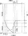
次に、上述のように構成された充電システム1の動作について説明する。図2は、図1に示す充電システム1の動作の一例を示す説明図である。横軸は時間の経過を示し、左の縦軸は組電池14の端子電圧Vtを示し、右の縦軸は組電池14に流れる充電電流Icを示している。また、以下の説明において、好適温度範囲内における第1電流値I1をI1A、好適温度範囲外における第1電流値I1をI1B、好適温度範囲内における第2電流値I2をI2A、好適温度範囲外における第2電流値I2をI2Bと記載する。
Next, the operation of the charging system 1 configured as described above will be described. FIG. 2 is an explanatory diagram showing an example of the operation of the charging system 1 shown in FIG. The horizontal axis indicates the passage of time, the left vertical axis indicates the terminal voltage Vt of the assembled
まず、温度センサ17によって、組電池14の温度tが検出される。そして、温度tが例えば10℃〜45℃の好適温度範囲内であれば、電流値設定部213によって、第1電流値I1が例えば0.70It(I1A)に設定され、第2電流値I2が例えば0.35It(I2A)に設定される。
First, the
次に、充電制御部212によって、通信部203,36を介して制御部37へ、第1電流値I1(I1A)の電流を要求する要求信号が送信される。そうすると、第1電流値I1(I1A)の充放電電流Icが充電回路35から出力されて組電池14が定電流充電される(タイミングT1)。
Next, the
そして、充電に伴い組電池14の端子電圧Vtが上昇する。そして、電圧検出回路15で検出された端子電圧Vtが第1閾値電圧Vth1以上になって、組電池14が充電電流により劣化しやすい状態になると、充電制御部212によって、通信部203,36を介して制御部37へ、充電電流Icを第1電流値I1(I1A)から第2電流値I2(I2A)へ変更させる要求信号が送信される。
And the terminal voltage Vt of the assembled
そうすると、充電回路35によって、定電流充電における電流値が第1電流値I1(I1A)から第2電流値I2(I2A)へ変更されて、充電電流が減少される(タイミングT2)。この場合、組電池14の端子電圧Vtが、第1閾値電圧Vth1以上の満充電電圧Vfull付近の電圧まで上昇して、組電池14が充電電流により劣化しやすい状態になったときに充電電流が減少するので、定電流充電における組電池14の劣化が低減される。
Then, the current value in the constant current charging is changed from the first current value I1 (I1A) to the second current value I2 (I2A) by the charging
ここで、組電池14の温度tが好適温度範囲外であった場合、温度tが好適温度範囲内である場合と比べて、充電電流により組電池14が劣化し易くなる。
Here, when the temperature t of the assembled
しかしながら、組電池14の温度tが好適温度範囲外であった場合、電流値設定部213によって、第1電流値I1が例えば0.35It(I1B)に減少され、第2電流値I2が例えば0.20It(I2B)に減少されるので、温度tが好適温度範囲内である場合よりも好適温度範囲外である場合の方が定電流充電における充電電流が減少される結果、電流値設定部213を用いない場合と比べて組電池14の劣化を低減することができる。
However, when the temperature t of the assembled
そして、第2電流値I2による定電流充電で組電池14が充電されて、電圧検出回路15で検出された端子電圧Vtが満充電電圧Vfull以上になると(タイミングT3)、充電制御部212は、通信部203,36を介して制御部37へ、満充電電圧Vfullの充電電圧を要求する要求信号を送信する。そうすると、満充電電圧Vfullの充電電圧が充電装置3から出力されて、組電池14の両端間に印加され、定電圧充電に移行する。そして、定電圧充電が進むにつれて組電池14に流れる充電電流Icが徐々に減少する。
When the assembled
そして、電流検出抵抗16により検出された充電電流Icが、充電終止電流値Ia以下になり、組電池14の開路電圧がほぼ満充電電圧Vfullに等しくなったとき、充電制御部212によって、通信部203,36を介して制御部37へ、充電電流Icをゼロにする要求信号が送信される。そうすると、充電装置3によって充電電流Icがゼロにされて、CCCV充電が終了する(タイミングT4)。
When the charging current Ic detected by the
なお、第1電流値I1及び第2電流値I2は、定電流充電の実行期間中において、電流値設定部213によってリアルタイムに更新される。図3は、定電流充電の実行期間中に温度tが変化した場合の充電システム1の動作の一例を示す説明図である。
The first current value I1 and the second current value I2 are updated in real time by the current
例えば、タイミングT5において、温度tが上昇するなどして好適温度範囲外になった場合、電流値設定部213によって、第1電流値I1が例えば0.35It(I1B)に減少され、第2電流値I2が例えば0.20It(I2B)に減少されるので、充電制御部212によって、充電装置3へ0.35It(I1B)の充電電流を要求する信号が送信されて、0.35It(I1B)による定電流充電が実行される。
For example, when the temperature t rises outside the preferred temperature range, for example, at the timing T5, the current
そして、充電に伴い組電池14の端子電圧Vtが上昇し、第1閾値電圧Vth1以上になると、充電制御部212によって、制御部37へ、充電電流Icを第1電流値I1B(0.35It)から第2電流値I2B(0.20It)へ変更させる要求信号が送信される。そうすると、充電回路35によって、定電流充電における電流値が第2電流値I2Bへ変更されて、充電電流が減少される(タイミングT6)。
When the terminal voltage Vt of the assembled
さらに、タイミングT7において、例えば組電池14の温度tが低下するなどして好適温度範囲内になった場合、電流値設定部213によって、第1電流値I1が例えば0.70It(I1A)に増大され、第2電流値I2が例えば0.35It(I2A)に増大される。そうすると、充電制御部212によって、充電装置3へ0.35It(I2A)の充電電流を要求する信号が送信されて、0.35It(I1B)による定電流充電が実行される(タイミングT7)。
Further, at timing T7, when the temperature t of the assembled
このように、組電池14の温度tが好適温度範囲外から好適温度範囲内に変化した場合、充電電流が増大されるので、一旦減少された充電電流がそのまま維持される場合と比べて充電時間が短縮される。
In this way, when the temperature t of the assembled
ところで、充電装置3に何らかの故障、例えば出力電流値の制御回路に故障が生じると、充電制御部212が充電装置3に要求した電流値より、実際に充電装置3から組電池14へ供給される電流値が増大して組電池14を劣化させてしまうおそれがある。
By the way, when some failure occurs in the charging device 3, for example, a failure occurs in the control circuit of the output current value, the charging
そこで、例えば電流検出抵抗16やアナログデジタル変換器201による電流検出誤差が△iであった場合、充電制御部212は、第1異常対応処理として、充電装置3に第1電流値I1を要求したときは、その第1電流値I1に△iを加算した値を第1電流値I1に対する異常電流閾値Ith(I1)として設定し、充電装置3に第2電流値I2を要求したときは、その第2電流値I2に△iを加算した値を第2電流値I2に対する異常電流閾値Ith(I2)として設定する。
Therefore, for example, when the current detection error by the
そうすると、電流検出抵抗16によって検出される電流値Icは、充電装置3が正常であれば異常電流閾値Ithを超えないはずであるから、もし電流値Icが異常電流閾値Ithを超えた場合、充電装置3に何らかの異常が生じていると考えられ、組電池14を劣化させてしまうおそれがある。
Then, the current value Ic detected by the
そこで、充電制御部212は、電流検出抵抗16によって検出される電流値Icが異常電流閾値Ithを超える場合、端子電圧Vtが満充電電圧Vfullまで上昇する前に、端子電圧Vtが、満充電電圧Vfullより低い電圧値に予め設定された第2閾値電圧Vth2以上になると、第2閾値電圧Vth2を充電電圧として、すなわち満充電電圧Vfullより低い電圧で、充電装置3によって組電池14を定電圧充電させる。
Therefore, when the current value Ic detected by the
図4は、例えば充電装置3における充電回路35等の電流制御回路の故障によって、充電制御部212の要求電流より充電装置3の出力電流が多くなった場合の第1異常対応処理の一例を説明するための説明図である。図4に示す例では、第2閾値電圧Vth2は、満充電電圧Vfullより低く、かつ第1閾値電圧Vth1より高い電圧値に設定されている。
FIG. 4 illustrates an example of a first abnormality handling process in the case where the output current of the charging device 3 is larger than the required current of the charging
図4に示す例では、充電制御部212が第1電流値I1Aを充電装置3に要求しているタイミングT1〜T2において、電流検出抵抗16によって検出される電流値Icが、異常電流閾値Ith(I1)を超えている。
In the example illustrated in FIG. 4, the current value Ic detected by the
そうすると、充電制御部212は、電圧検出回路15によって検出された端子電圧Vtが、第2閾値電圧Vth2以上になったタイミングT8において、充電装置3に第2閾値電圧Vth2の電圧出力を要求して以後、定電圧充電に切り替える。
Then, the charging
この場合、もし仮に、充電装置3が、充電制御部212が要求している電流値(第1電流値I1A)を超えているにもかかわらず、端子電圧Vtが満充電電圧Vfullになるまで定電流充電を継続したとすれば、組電池14の劣化が生じやすい満充電電圧Vfull付近まで充電制御部212の要求電流を超える充電電流が組電池14に流れて劣化するおそれがある。
In this case, if the charging device 3 exceeds the current value (first current value I1A) requested by the charging
しかしながら、充電制御部212は、端子電圧Vtが第2閾値電圧Vth2以上になったタイミングT8において、充電装置3に第2閾値電圧Vth2の電圧出力を要求して定電圧充電に切り替えるので、タイミングT8以後の充電電流が減少する結果、組電池14が劣化するおそれが低減される。
However, the charging
このように、充電装置3の電流制御回路が故障していても、電圧制御は正常にできる場合があるので、定電流充電から、満充電電圧Vfullより低い第2閾値電圧Vth2での定電圧充電に切り替えることにより、組電池14が劣化するおそれを低減しつつ、組電池14を使い続けることが可能となる。
Thus, even if the current control circuit of the charging device 3 is out of order, the voltage control may be able to be performed normally. Therefore, the constant voltage charging from the constant current charging to the second threshold voltage Vth2 lower than the full charging voltage Vfull is possible. By switching to, it becomes possible to continue using the assembled
例えば、組電池14が、電気自動車等の電源として使用されている場合、何らかの異常があっても直ちに使用を禁止してしまうと支障を生じるおそれがある。そこで、例え充電装置3が故障しているおそれがあっても、可能な範囲で組電池14の使用を継続するようにすることが望ましく、充電制御回路4は、このような用途に好適である。
For example, when the assembled
なお、第2閾値電圧Vth2が第1閾値電圧Vth1より高い電圧値に設定される例を示したが、第2閾値電圧Vth2は第1閾値電圧Vth1以下の電圧値に設定されていてもよい。 In addition, although the example in which the second threshold voltage Vth2 is set to a voltage value higher than the first threshold voltage Vth1 is shown, the second threshold voltage Vth2 may be set to a voltage value equal to or lower than the first threshold voltage Vth1.
また、異常電流閾値Ithが、要求電流値に応じて変化する例を示したが、異常電流閾値Ithは、例えば充電制御回路4が充電装置3に要求する可能性のある最大の電流値である第1電流値I1Aより大きい電流値に固定的に設定されていてもよい。
Moreover, although the example in which the abnormal current threshold value Ith changes according to the required current value has been shown, the abnormal current threshold value Ith is, for example, the maximum current value that the charging
ここで、例えば充電装置3の出力電圧値の制御回路にも故障が生じる等して充電制御部212が充電装置3に要求した電圧値より、実際に充電装置3から組電池14へ供給される電圧値が大きくなると、組電池14を劣化させたり、安全性が低下したりするおそれがある。
Here, for example, a failure occurs in the output voltage value control circuit of the charging device 3, and the charging
そこで、充電制御部212は、第2異常対応処理を実行する。図5は、充電制御部212による第2異常対応処理を説明するための説明図である。
Therefore, the charging
まず、例えば電圧検出回路15やアナログデジタル変換器201による電圧検出誤差が△vであった場合、充電制御部212は、第2異常対応処理として、充電装置3に要求した電圧値、例えば第2閾値電圧Vth2に△vを加算した値を異常電圧閾値Vteとして設定する。
First, when the voltage detection error by the
そして、充電制御部212は、タイミングT1〜T8において、上述の第1異常対応処理を実行する。そして、充電電圧(要求電圧)を第2閾値電圧Vth2とする定電圧充電が実行されている期間中においても端子電圧Vtの上昇が継続し、端子電圧Vtが異常電圧閾値Vteを超えた場合、充電装置3に何らかの異常が生じていると考えられる。
And the
そこで、充電制御部212は、端子電圧Vtが異常電圧閾値Vteを超えると(タイミングT9)、スイッチング素子Q2をオフして充電を禁止することで、充電装置3の異常に起因して組電池14が劣化したり、安全性が低下したりするおそれを低減する。
Therefore, when the terminal voltage Vt exceeds the abnormal voltage threshold Vte (timing T9), the charging
なお、異常電圧閾値Vteは、第2閾値電圧Vth2に△vを加算した値に限られず、例えば満充電電圧Vfullと同じ電圧値に設定されていてもよい。 The abnormal voltage threshold Vte is not limited to the value obtained by adding Δv to the second threshold voltage Vth2, and may be set to the same voltage value as the full charge voltage Vfull, for example.
同様に、各制御閾値(Vth1,Vth2,Vte)をセル(セルブロック)電圧相当で制御することが望ましい。即ち、充電時にはセル電圧が最大のセルが最も劣化していることが推定できるので、各セルブロックの電圧を測定しその最大電圧値が、この閾値電圧を超えるか否かで制御することが劣化抑制には望ましい。 Similarly, it is desirable to control each control threshold value (Vth1, Vth2, Vte) with a cell (cell block) voltage equivalent. In other words, since it can be estimated that the cell with the largest cell voltage is most deteriorated during charging, it is deteriorated that the voltage of each cell block is measured and the maximum voltage value is controlled by whether or not this threshold voltage is exceeded. Desirable for suppression.
また、保護回路4は、電流値設定部213を備えない構成としてもよい。また、充電制御部212は、第1異常対応処理や第2異常対応処理を実行しない構成としてもよい。
The
本発明は、携帯型パーソナルコンピュータやデジタルカメラ、携帯電話機等の電子機器、電気自動車やハイブリッドカー等の車両、等の電池搭載装置において、二次電池の充電を制御する充電制御回路、及びこれを備えた電池パック、充電システムとして好適に利用することができる。 The present invention relates to a charging control circuit that controls charging of a secondary battery in a battery-mounted device such as a portable personal computer, a digital camera, an electronic device such as a mobile phone, a vehicle such as an electric vehicle or a hybrid car, and the like. The battery pack and the charging system provided can be suitably used.
1 充電システム
2 電池パック
3 充電装置
4 充電制御回路
11,12,13,31,32,33 接続端子
14 組電池
15 電圧検出回路
16 電流検出抵抗
17 温度センサ
35 充電回路
36,203 通信部
37,202 制御部
141,142,143 二次電池
201 アナログデジタル変換器
211 保護制御部
212 充電制御部
213 電流値設定部
Q1,Q2 スイッチング素子
I1,I1A,I1B 第1電流値
I2,I2A,I2B 第2電流値
Ia 充電終止電流値
Ith 異常電流閾値
Vt,V1,V2,V3 端子電圧
Vfull 満充電電圧
Vte 異常電圧閾値
Vth1 第1閾値電圧
Vth2 第2閾値電圧
DESCRIPTION OF SYMBOLS 1 Charging system 2 Battery pack 3
Claims (7)
前記二次電池の端子電圧を検出する電圧検出部と、
前記二次電池に流れる電流を検出する電流検出部とを備え、
前記充電制御部は、
前記電流検出部によって検出される電流値が、前記充電部へ要求した電流値を超える値に設定された異常電流閾値を超える場合において、前記電圧検出部によって検出される二次電池の端子電圧が、前記二次電池が満充電になったときの端子電圧である満充電電圧より低い電圧値に予め設定された第2閾値電圧以上になると、当該第2閾値電圧の充電電圧を前記充電部へ要求し、前記二次電池に供給させて定電圧充電を実行させる第1異常対応処理を実行する充電制御回路。 A charge control unit for controlling the operation of the charging unit for charging the secondary battery;
A voltage detector for detecting a terminal voltage of the secondary battery ;
A current detection unit for detecting a current flowing in the secondary battery ,
The charge controller is
When the current value detected by the current detection unit exceeds the abnormal current threshold set to a value exceeding the current value requested to the charging unit, the terminal voltage of the secondary battery detected by the voltage detection unit is When the secondary battery becomes equal to or higher than a second threshold voltage preset to a voltage value lower than the full charge voltage, which is a terminal voltage when the secondary battery is fully charged, the charging voltage of the second threshold voltage is sent to the charging unit. A charge control circuit that executes a first abnormality handling process that requests and supplies the secondary battery to perform constant voltage charging .
前記電圧検出部によって検出される二次電池の端子電圧が、前記二次電池が満充電になったときの端子電圧である満充電電圧より低い電圧値に予め設定された第1閾値電圧より低いとき、所定の第1電流値の充電電流を前記充電部に要求することにより、当該充電部によって当該充電電流を前記二次電池へ供給させて定電流充電を実行させ、
前記電圧検出部によって検出される二次電池の端子電圧が前記第1閾値電圧を超え、かつ前記満充電電圧に満たないとき、前記第1電流値より少ない第2電流値の充電電流を前記充電部に要求することにより、当該充電部によって当該充電電流を前記二次電池へ供給させて定電流充電を実行させ、
前記電圧検出部によって検出される二次電池の端子電圧が前記満充電電圧以上になると、前記充電部によって、当該満充電電圧を充電電圧として前記二次電池に供給させて定電圧充電を実行させる請求項1記載の充電制御回路。 Before Symbol charge control unit,
The terminal voltage of the secondary battery detected by the voltage detection unit is lower than a first threshold voltage set in advance to a voltage value lower than a full charge voltage that is a terminal voltage when the secondary battery is fully charged. When the charging unit requests a charging current having a predetermined first current value, the charging unit supplies the charging current to the secondary battery to perform constant current charging.
When the terminal voltage of the secondary battery detected by the voltage detector exceeds the first threshold voltage and is less than the full charge voltage, a charging current having a second current value smaller than the first current value is charged. By requesting the unit, the charging unit causes the charging current to be supplied to the secondary battery to perform constant current charging,
When the terminal voltage of the secondary battery detected by the voltage detection unit is equal to or higher than the full charge voltage, the charging unit supplies the full charge voltage as a charge voltage to the secondary battery to perform constant voltage charging. The charge control circuit according to claim 1 .
前記温度検出部によって検出される温度が、前記二次電池の充電に適した温度として予め設定された好適温度範囲の範囲外になったとき、前記第1及び第2電流値のうち少なくとも一方を減少させる電流値設定部とをさらに備えること
を特徴とする請求項2記載の充電制御回路。 A temperature detector for detecting the temperature of the secondary battery;
When the temperature detected by the temperature detection unit falls outside the range of a suitable temperature range preset as a temperature suitable for charging the secondary battery, at least one of the first and second current values is set. A current value setting unit for reducing the current value;
The charge control circuit according to claim 2 .
前記充電制御部は、
前記第1異常対応処理において、前記電圧検出部によって検出される二次電池の端子電圧が、前記充電部へ要求した前記第2閾値電圧を超える値に設定された異常電圧閾値を超える場合、前記充電禁止部によって、前記二次電池の充電を禁止させる第2異常対応処理を実行すること
を特徴とする請求項1〜3のいずれか1項に記載の充電制御回路。 A charge prohibition unit for prohibiting charging of the secondary battery;
The charge controller is
In the first abnormality handling process, when the terminal voltage of the secondary battery detected by the voltage detection unit exceeds the abnormal voltage threshold set to a value exceeding the second threshold voltage requested to the charging unit, The charge control circuit according to any one of claims 1 to 3 , wherein a charge prohibition unit executes a second abnormality handling process for prohibiting charging of the secondary battery.
複数のセルが組み合わされた組電池であり、
前記電圧検出部は、
前記複数のセルの端子電圧をそれぞれ検出し、
前記充電制御部は、
前記組電池が満充電になったときの1セルあたりの端子電圧を、前記満充電電圧として用い、
前記電圧検出部によって検出された前記各セルの端子電圧のうち、最大の電圧を、前記二次電池の端子電圧として用い、
前記定電圧充電においては、前記二次電池に含まれるセルあたりの印加電圧が、前記1セルあたりの満充電電圧となるように、前記充電部によって前記二次電池へ充電電圧を供給させること
を特徴とする請求項1〜4のいずれか1項に記載の充電制御回路。 The secondary battery is
An assembled battery in which a plurality of cells are combined,
The voltage detector is
Detecting a terminal voltage of each of the plurality of cells;
The charge controller is
The terminal voltage per cell when the assembled battery is fully charged is used as the fully charged voltage,
Among the terminal voltages of the cells detected by the voltage detector, the maximum voltage is used as the terminal voltage of the secondary battery,
In the constant voltage charging, the charging unit supplies a charging voltage to the secondary battery so that an applied voltage per cell included in the secondary battery becomes a full charging voltage per cell. The charge control circuit according to claim 1, wherein the charge control circuit is characterized in that:
前記二次電池と、
を備えることを特徴とする電池パック。 The charge control circuit according to any one of claims 1 to 5,
The secondary battery;
A battery pack comprising:
前記二次電池と、
前記充電部と
を備えることを特徴とする充電システム。 The charge control circuit according to any one of claims 1 to 5,
The secondary battery;
A charging system comprising: the charging unit.
Priority Applications (4)
| Application Number | Priority Date | Filing Date | Title |
|---|---|---|---|
| JP2009145264A JP4966998B2 (en) | 2009-06-18 | 2009-06-18 | Charge control circuit, battery pack, and charging system |
| PCT/JP2010/003767 WO2010146795A1 (en) | 2009-06-18 | 2010-06-04 | Charging control circuit, battery pack, and charging system |
| US13/142,971 US8796996B2 (en) | 2009-06-18 | 2010-06-04 | Charge control circuit, battery pack, and charge system |
| CN201080003981.5A CN102326313B (en) | 2009-06-18 | 2010-06-04 | Charging control circuit, battery pack, and charging system |
Applications Claiming Priority (1)
| Application Number | Priority Date | Filing Date | Title |
|---|---|---|---|
| JP2009145264A JP4966998B2 (en) | 2009-06-18 | 2009-06-18 | Charge control circuit, battery pack, and charging system |
Publications (3)
| Publication Number | Publication Date |
|---|---|
| JP2011004509A JP2011004509A (en) | 2011-01-06 |
| JP2011004509A5 JP2011004509A5 (en) | 2012-03-15 |
| JP4966998B2 true JP4966998B2 (en) | 2012-07-04 |
Family
ID=43356129
Family Applications (1)
| Application Number | Title | Priority Date | Filing Date |
|---|---|---|---|
| JP2009145264A Active JP4966998B2 (en) | 2009-06-18 | 2009-06-18 | Charge control circuit, battery pack, and charging system |
Country Status (4)
| Country | Link |
|---|---|
| US (1) | US8796996B2 (en) |
| JP (1) | JP4966998B2 (en) |
| CN (1) | CN102326313B (en) |
| WO (1) | WO2010146795A1 (en) |
Families Citing this family (68)
| Publication number | Priority date | Publication date | Assignee | Title |
|---|---|---|---|---|
| JP5416735B2 (en) * | 2011-04-28 | 2014-02-12 | 株式会社日立製作所 | Power monitoring control device and power monitoring control system |
| JP5648581B2 (en) * | 2011-05-25 | 2015-01-07 | 新神戸電機株式会社 | Electric cart equipped with lithium ion battery and charging method of lithium ion battery for electric cart |
| JP5879557B2 (en) * | 2011-09-12 | 2016-03-08 | パナソニックIpマネジメント株式会社 | Charger |
| DE102011088349A1 (en) * | 2011-12-13 | 2013-06-13 | Sb Limotive Company Ltd. | Battery, motor vehicle and method for operating the battery |
| TWI464997B (en) * | 2012-05-02 | 2014-12-11 | Wistron Corp | Battery charging circuit |
| JP2013243823A (en) * | 2012-05-18 | 2013-12-05 | Sanyo Electric Co Ltd | Charging voltage changing method of secondary battery and battery pack |
| US9923395B2 (en) | 2012-09-18 | 2018-03-20 | Sonova Ag | Method for charging a NIMH battery, a battery charger and a system comprising a battery charger and a hearing device |
| US9831691B2 (en) * | 2012-09-18 | 2017-11-28 | Nec Energy Devices, Ltd. | Power storage system and cell protection method which protects the cell by both cutting from the cell pack and the cell pack from the system |
| EP2903127A4 (en) * | 2012-09-28 | 2016-06-08 | Hitachi Koki Kk | Charging device |
| KR20140044105A (en) * | 2012-10-04 | 2014-04-14 | 삼성에스디아이 주식회사 | Apparatus and method for charging battery |
| JP2014087200A (en) * | 2012-10-25 | 2014-05-12 | Nec Personal Computers Ltd | Charger, charging method, program, and information processing apparatus |
| JP6123046B2 (en) * | 2013-03-06 | 2017-05-10 | エリーパワー株式会社 | Charge current control circuit |
| JP6168813B2 (en) * | 2013-03-29 | 2017-07-26 | 株式会社ケーヒン | Voltage detector |
| CN105308822B (en) * | 2013-06-14 | 2019-06-07 | 联发科技股份有限公司 | Mancarried device, battery pack and the method used between the two |
| RU2627243C1 (en) * | 2013-08-09 | 2017-08-04 | Хитачи Аутомотив Системс, Лтд. | Storage battery control system and vehicle control system |
| CN105706328B (en) * | 2013-10-29 | 2018-11-02 | 三菱电机株式会社 | The trouble-shooter and method for diagnosing faults of discharge circuit |
| JP6188169B2 (en) * | 2013-11-01 | 2017-08-30 | 日本電気株式会社 | Charging device, power storage system, charging method and program |
| JP6265215B2 (en) * | 2013-11-01 | 2018-01-24 | 日本電気株式会社 | Charging device, power storage system, charging method and program |
| CN103746434B (en) | 2014-01-28 | 2016-04-06 | 广东欧珀移动通信有限公司 | Charging method and system |
| CN104836261A (en) * | 2014-02-07 | 2015-08-12 | 鸿富锦精密工业(深圳)有限公司 | Battery pack charging control method and apparatus |
| JP2015154593A (en) * | 2014-02-14 | 2015-08-24 | ソニー株式会社 | Charge/discharge control device, battery pack, electronic apparatus, electric motor vehicle and charge/discharge control method |
| US9455582B2 (en) | 2014-03-07 | 2016-09-27 | Apple Inc. | Electronic device and charging device for electronic device |
| CN105098862A (en) * | 2014-05-19 | 2015-11-25 | 中兴通讯股份有限公司 | Charging control method, charging control device and charging control terminal |
| CN106463997B (en) * | 2014-06-13 | 2018-04-06 | 日产自动车株式会社 | Battery charge controller and charge control method |
| CN104201727B (en) * | 2014-08-01 | 2017-04-12 | 惠州Tcl移动通信有限公司 | Rapid charging method and device |
| US10211655B2 (en) | 2014-08-14 | 2019-02-19 | Mediatek Inc. | Scheme for activating or deactivating shipping mode for battery via battery connecting interface without additional signal port(s) |
| US9917335B2 (en) | 2014-08-28 | 2018-03-13 | Apple Inc. | Methods for determining and controlling battery expansion |
| CN104241719A (en) * | 2014-08-30 | 2014-12-24 | 重庆长安汽车股份有限公司 | Quick charging control method for electric automobiles |
| US20160064961A1 (en) * | 2014-09-02 | 2016-03-03 | Apple Inc. | User-behavior-driven battery charging |
| CN105703023A (en) * | 2014-11-28 | 2016-06-22 | 奇点新源国际技术开发(北京)有限公司 | Charging-discharging method and apparatus for standby battery of vehicle-mounted terminal |
| JP6355552B2 (en) * | 2014-12-25 | 2018-07-11 | マクセルホールディングス株式会社 | Lithium ion secondary battery charging method and charging control system thereof |
| CN106410303B (en) * | 2015-07-27 | 2019-02-19 | 小米科技有限责任公司 | Charging method and device |
| CN106712130A (en) * | 2015-07-31 | 2017-05-24 | 苏州易能微电子科技有限公司 | Novel charging control system and method |
| US10211659B2 (en) * | 2015-09-24 | 2019-02-19 | Guangdong Oppo Mobile Telecommunications Corp., Ltd. | Charging method and apparatus for rechargeable battery |
| CN105553050B (en) * | 2016-02-26 | 2018-10-23 | 宁波萨瑞通讯有限公司 | A kind of adaptive charging method and system |
| US10124725B2 (en) * | 2016-03-01 | 2018-11-13 | Ford Global Technologies, Llc | Customizable vehicle charge status tones |
| JP6759668B2 (en) * | 2016-03-31 | 2020-09-23 | 株式会社Gsユアサ | Power storage element management device, power storage device, and power storage system |
| JP6639999B2 (en) * | 2016-03-31 | 2020-02-05 | 株式会社マキタ | Charging device |
| KR101674855B1 (en) * | 2016-04-01 | 2016-11-09 | 배문수 | System for protecting lithium batterie in low temperature condition |
| US10447054B2 (en) * | 2016-05-20 | 2019-10-15 | Robert Bosch Gmbh | Staircase charging |
| DE102016213070B4 (en) * | 2016-07-18 | 2017-05-11 | Continental Automotive Gmbh | Vehicle electrical system and procedure |
| JP6828296B2 (en) * | 2016-08-09 | 2021-02-10 | 株式会社Gsユアサ | Power storage device and charge control method for power storage device |
| US10148101B2 (en) * | 2016-08-12 | 2018-12-04 | Mediatek Inc. | Battery charging system and battery charging protection control method |
| CN107947252B (en) * | 2016-10-12 | 2020-09-22 | Oppo广东移动通信有限公司 | Terminal and equipment |
| CN209488195U (en) * | 2016-10-12 | 2019-10-11 | Oppo广东移动通信有限公司 | Mobile terminal |
| US10985590B2 (en) * | 2016-11-01 | 2021-04-20 | Samsung Electronics Co., Ltd. | Method and apparatus for charging battery |
| US10790689B2 (en) * | 2016-11-18 | 2020-09-29 | Fairchild Semiconductor Corporation | Intelligent contact charging devices and methods |
| US11011784B2 (en) | 2017-03-21 | 2021-05-18 | Toyota Motor Europe | Method for charging a non-aqueous metal air battery using constant currents or constant voltages, and corresponding device |
| PT3462565T (en) | 2017-04-13 | 2021-04-19 | Guangdong Oppo Mobile Telecommunications Corp Ltd | Device to be charged and charging method |
| CN107069888B (en) * | 2017-05-22 | 2020-09-11 | 维沃移动通信有限公司 | Charging circuit and mobile terminal |
| CN107332316B (en) * | 2017-08-23 | 2021-11-02 | 努比亚技术有限公司 | Stepped charging method, mobile terminal and computer-readable storage medium |
| CN109952515A (en) * | 2017-08-25 | 2019-06-28 | 深圳市云中飞网络科技有限公司 | Terminal device, adapter, cell safety monitoring method and monitoring system |
| JP6756754B2 (en) * | 2018-02-09 | 2020-09-16 | ミツミ電機株式会社 | Charge control device, charging system and charge control method |
| CA3061923C (en) * | 2018-05-31 | 2024-02-20 | Guangdong Oppo Mobile Telecommunications Corp., Ltd. | Charging method and charging apparatus |
| CN108777331B (en) * | 2018-06-08 | 2021-04-30 | 广东小天才科技有限公司 | Charging control method and device for lithium ion battery in electronic equipment |
| CN110620406A (en) * | 2018-06-18 | 2019-12-27 | Oppo广东移动通信有限公司 | Quick charging method and device for battery, equipment to be charged and charging system |
| AU2019101785A4 (en) | 2018-08-06 | 2021-04-01 | Techtronic Cordless Gp | Systems and methods for selectively enabling the operation of a device |
| JP6985999B2 (en) * | 2018-09-18 | 2021-12-22 | カシオ計算機株式会社 | Charge protection circuit, charging device, electronic device and charge protection method |
| WO2020059844A1 (en) * | 2018-09-21 | 2020-03-26 | 株式会社Gsユアサ | Charging control device, charging control method |
| JP2020054224A (en) * | 2018-09-21 | 2020-04-02 | 株式会社Gsユアサ | Charge control device, charge control method |
| CN113196546A (en) | 2018-12-20 | 2021-07-30 | 株式会社半导体能源研究所 | Semiconductor device and battery pack |
| CN116094107A (en) | 2018-12-21 | 2023-05-09 | Oppo广东移动通信有限公司 | Charging control method and device and computer storage medium |
| CN112889199A (en) * | 2018-12-27 | 2021-06-01 | Oppo广东移动通信有限公司 | Charging method and device, equipment to be charged, storage medium and chip system |
| JP2020205667A (en) * | 2019-06-14 | 2020-12-24 | 工機ホールディングス株式会社 | Charger |
| TWI707521B (en) * | 2019-07-01 | 2020-10-11 | 飛宏科技股份有限公司 | Intelligence ac to dc maximum power charging management method of a battery charger |
| JP7251415B2 (en) * | 2019-09-04 | 2023-04-04 | 株式会社豊田自動織機 | charging controller |
| JP7294007B2 (en) * | 2019-09-05 | 2023-06-20 | 三菱電機株式会社 | Power supply and emergency lighting |
| CN115832474A (en) * | 2021-11-29 | 2023-03-21 | 宁德时代新能源科技股份有限公司 | Battery charging method, battery and electric energy equipment |
Family Cites Families (16)
| Publication number | Priority date | Publication date | Assignee | Title |
|---|---|---|---|---|
| US5442274A (en) | 1992-08-27 | 1995-08-15 | Sanyo Electric Company, Ltd. | Rechargeable battery charging method |
| JP3152512B2 (en) | 1992-08-27 | 2001-04-03 | 三洋電機株式会社 | Charging method |
| JP3291530B2 (en) * | 1992-09-17 | 2002-06-10 | ソニー株式会社 | Battery protection circuit |
| JPH1014125A (en) * | 1996-06-25 | 1998-01-16 | Matsushita Electric Ind Co Ltd | Method and device for charging nickel-cadonium or nickel-hydrogen secondary battery |
| JP3327790B2 (en) * | 1996-10-29 | 2002-09-24 | エヌイーシートーキン栃木株式会社 | Battery protection device |
| JP3378189B2 (en) * | 1998-02-28 | 2003-02-17 | 株式会社マキタ | Charging device and charging method |
| JP2001178011A (en) * | 1999-12-10 | 2001-06-29 | Toshiba Battery Co Ltd | Secondary cell device |
| JP4605952B2 (en) * | 2001-08-29 | 2011-01-05 | 株式会社日立製作所 | Power storage device and control method thereof |
| JP3799294B2 (en) * | 2002-05-15 | 2006-07-19 | ソニー株式会社 | Charger |
| JP4130425B2 (en) * | 2003-07-29 | 2008-08-06 | パナソニックEvエナジー株式会社 | Secondary battery charge / discharge quantity estimation method and apparatus, secondary battery polarization voltage estimation method and apparatus, and secondary battery remaining capacity estimation method and apparatus |
| JP5029862B2 (en) * | 2006-03-31 | 2012-09-19 | 日立工機株式会社 | Charger |
| JP2008206259A (en) | 2007-02-19 | 2008-09-04 | Matsushita Electric Ind Co Ltd | Charging system, charger, and battery pack |
| JP2008259293A (en) | 2007-04-04 | 2008-10-23 | Yamaha Motor Co Ltd | Charging device of secondary battery |
| JP4966822B2 (en) * | 2007-10-30 | 2012-07-04 | パナソニック株式会社 | Charging system and battery pack |
| JP5091634B2 (en) * | 2007-11-15 | 2012-12-05 | パナソニック株式会社 | Battery pack and charging system |
| JP4591560B2 (en) * | 2008-06-24 | 2010-12-01 | ソニー株式会社 | Battery pack and control method |
-
2009
- 2009-06-18 JP JP2009145264A patent/JP4966998B2/en active Active
-
2010
- 2010-06-04 CN CN201080003981.5A patent/CN102326313B/en active Active
- 2010-06-04 US US13/142,971 patent/US8796996B2/en active Active
- 2010-06-04 WO PCT/JP2010/003767 patent/WO2010146795A1/en active Application Filing
Also Published As
| Publication number | Publication date |
|---|---|
| CN102326313A (en) | 2012-01-18 |
| US20110267009A1 (en) | 2011-11-03 |
| JP2011004509A (en) | 2011-01-06 |
| US8796996B2 (en) | 2014-08-05 |
| CN102326313B (en) | 2014-10-29 |
| WO2010146795A1 (en) | 2010-12-23 |
Similar Documents
| Publication | Publication Date | Title |
|---|---|---|
| JP4966998B2 (en) | Charge control circuit, battery pack, and charging system | |
| JP2011004509A5 (en) | ||
| US9484763B2 (en) | Battery pack and method of controlling the same | |
| US9184615B2 (en) | Battery pack and method of controlling the same | |
| JP5363740B2 (en) | Charge control circuit, battery pack, and charging system | |
| US8183832B2 (en) | Charging system, charger, and battery pack | |
| CN101816092B (en) | Secondary cell charge control method and charge control circuit | |
| JP5174421B2 (en) | Battery pack and battery system | |
| EP2410602B1 (en) | Charging and discharging method for lithium ion secondary batteries and charging and discharging system for the same | |
| US8476869B2 (en) | Battery voltage equalizer circuit and method for using the same | |
| JP5091634B2 (en) | Battery pack and charging system | |
| JP6137631B2 (en) | Secondary battery pack and authentication method | |
| JP5122214B2 (en) | Battery pack, charging device, and charging system | |
| WO2010113206A1 (en) | Charging device | |
| KR20130086563A (en) | Charge control apparatus and battery pack with protection function | |
| JP2009225632A (en) | Charging control circuit, battery pack, and charging system | |
| US11482869B2 (en) | Electric storage system | |
| JP2009264779A (en) | Battery state detection circuit, battery pack, and charging system | |
| JP2009254165A (en) | Battery state detection circuit, battery pack, and charging system | |
| JP4878573B2 (en) | Battery protection circuit and battery pack | |
| JP5165405B2 (en) | Charge control circuit, battery pack, and charging system | |
| JP5049162B2 (en) | Fault diagnosis circuit and battery pack provided with the same | |
| TW201338241A (en) | Storage device and charge-discharge method thereof | |
| JP2009038960A (en) | Charging system, and battery pack | |
| JP6647662B1 (en) | Battery pack unit and cell balance adjustment method |
Legal Events
| Date | Code | Title | Description |
|---|---|---|---|
| A521 | Request for written amendment filed |
Free format text: JAPANESE INTERMEDIATE CODE: A523 Effective date: 20120127 |
|
| A621 | Written request for application examination |
Free format text: JAPANESE INTERMEDIATE CODE: A621 Effective date: 20120127 |
|
| A871 | Explanation of circumstances concerning accelerated examination |
Free format text: JAPANESE INTERMEDIATE CODE: A871 Effective date: 20120127 |
|
| A975 | Report on accelerated examination |
Free format text: JAPANESE INTERMEDIATE CODE: A971005 Effective date: 20120227 |
|
| TRDD | Decision of grant or rejection written | ||
| A01 | Written decision to grant a patent or to grant a registration (utility model) |
Free format text: JAPANESE INTERMEDIATE CODE: A01 Effective date: 20120327 |
|
| A01 | Written decision to grant a patent or to grant a registration (utility model) |
Free format text: JAPANESE INTERMEDIATE CODE: A01 |
|
| A61 | First payment of annual fees (during grant procedure) |
Free format text: JAPANESE INTERMEDIATE CODE: A61 Effective date: 20120402 |
|
| R150 | Certificate of patent or registration of utility model |
Ref document number: 4966998 Country of ref document: JP Free format text: JAPANESE INTERMEDIATE CODE: R150 Free format text: JAPANESE INTERMEDIATE CODE: R150 |
|
| FPAY | Renewal fee payment (event date is renewal date of database) |
Free format text: PAYMENT UNTIL: 20150406 Year of fee payment: 3 |
|
| R250 | Receipt of annual fees |
Free format text: JAPANESE INTERMEDIATE CODE: R250 |