JP4963402B2 - Manufacturing method of resin molded products - Google Patents
Manufacturing method of resin molded products Download PDFInfo
- Publication number
- JP4963402B2 JP4963402B2 JP2006297643A JP2006297643A JP4963402B2 JP 4963402 B2 JP4963402 B2 JP 4963402B2 JP 2006297643 A JP2006297643 A JP 2006297643A JP 2006297643 A JP2006297643 A JP 2006297643A JP 4963402 B2 JP4963402 B2 JP 4963402B2
- Authority
- JP
- Japan
- Prior art keywords
- gate
- compression
- product
- resin
- cutting
- Prior art date
- Legal status (The legal status is an assumption and is not a legal conclusion. Google has not performed a legal analysis and makes no representation as to the accuracy of the status listed.)
- Expired - Fee Related
Links
- 239000011347 resin Substances 0.000 title claims description 61
- 229920005989 resin Polymers 0.000 title claims description 61
- 238000004519 manufacturing process Methods 0.000 title claims description 9
- 238000005520 cutting process Methods 0.000 claims description 109
- 230000006835 compression Effects 0.000 claims description 55
- 238000007906 compression Methods 0.000 claims description 55
- 238000000034 method Methods 0.000 claims description 21
- 238000000465 moulding Methods 0.000 claims description 14
- 238000002347 injection Methods 0.000 claims description 4
- 239000007924 injection Substances 0.000 claims description 4
- 238000003825 pressing Methods 0.000 claims description 2
- 230000007246 mechanism Effects 0.000 description 12
- 208000015943 Coeliac disease Diseases 0.000 description 11
- 238000001816 cooling Methods 0.000 description 10
- 238000010586 diagram Methods 0.000 description 8
- 238000001746 injection moulding Methods 0.000 description 8
- 230000008569 process Effects 0.000 description 8
- 239000000463 material Substances 0.000 description 7
- 230000003287 optical effect Effects 0.000 description 6
- 238000007711 solidification Methods 0.000 description 5
- 230000008023 solidification Effects 0.000 description 5
- 230000008859 change Effects 0.000 description 2
- 230000009969 flowable effect Effects 0.000 description 2
- 229910052751 metal Inorganic materials 0.000 description 2
- 239000002184 metal Substances 0.000 description 2
- 239000002699 waste material Substances 0.000 description 2
- 230000002411 adverse Effects 0.000 description 1
- 229910052782 aluminium Inorganic materials 0.000 description 1
- XAGFODPZIPBFFR-UHFFFAOYSA-N aluminium Chemical compound [Al] XAGFODPZIPBFFR-UHFFFAOYSA-N 0.000 description 1
- 230000008901 benefit Effects 0.000 description 1
- 239000000919 ceramic Substances 0.000 description 1
- 238000007796 conventional method Methods 0.000 description 1
- 230000007547 defect Effects 0.000 description 1
- 230000003111 delayed effect Effects 0.000 description 1
- 238000013461 design Methods 0.000 description 1
- 238000004512 die casting Methods 0.000 description 1
- 239000000203 mixture Substances 0.000 description 1
- 238000010068 moulding (rubber) Methods 0.000 description 1
- 230000002093 peripheral effect Effects 0.000 description 1
- 238000012545 processing Methods 0.000 description 1
- 230000004044 response Effects 0.000 description 1
- 238000007493 shaping process Methods 0.000 description 1
- 238000012546 transfer Methods 0.000 description 1
Images


Classifications
-
- B—PERFORMING OPERATIONS; TRANSPORTING
- B29—WORKING OF PLASTICS; WORKING OF SUBSTANCES IN A PLASTIC STATE IN GENERAL
- B29C—SHAPING OR JOINING OF PLASTICS; SHAPING OF MATERIAL IN A PLASTIC STATE, NOT OTHERWISE PROVIDED FOR; AFTER-TREATMENT OF THE SHAPED PRODUCTS, e.g. REPAIRING
- B29C45/00—Injection moulding, i.e. forcing the required volume of moulding material through a nozzle into a closed mould; Apparatus therefor
- B29C45/17—Component parts, details or accessories; Auxiliary operations
- B29C45/46—Means for plasticising or homogenising the moulding material or forcing it into the mould
- B29C45/56—Means for plasticising or homogenising the moulding material or forcing it into the mould using mould parts movable during or after injection, e.g. injection-compression moulding
- B29C45/561—Injection-compression moulding
-
- B—PERFORMING OPERATIONS; TRANSPORTING
- B29—WORKING OF PLASTICS; WORKING OF SUBSTANCES IN A PLASTIC STATE IN GENERAL
- B29C—SHAPING OR JOINING OF PLASTICS; SHAPING OF MATERIAL IN A PLASTIC STATE, NOT OTHERWISE PROVIDED FOR; AFTER-TREATMENT OF THE SHAPED PRODUCTS, e.g. REPAIRING
- B29C45/00—Injection moulding, i.e. forcing the required volume of moulding material through a nozzle into a closed mould; Apparatus therefor
- B29C45/17—Component parts, details or accessories; Auxiliary operations
- B29C45/38—Cutting-off equipment for sprues or ingates
-
- Y—GENERAL TAGGING OF NEW TECHNOLOGICAL DEVELOPMENTS; GENERAL TAGGING OF CROSS-SECTIONAL TECHNOLOGIES SPANNING OVER SEVERAL SECTIONS OF THE IPC; TECHNICAL SUBJECTS COVERED BY FORMER USPC CROSS-REFERENCE ART COLLECTIONS [XRACs] AND DIGESTS
- Y10—TECHNICAL SUBJECTS COVERED BY FORMER USPC
- Y10T—TECHNICAL SUBJECTS COVERED BY FORMER US CLASSIFICATION
- Y10T428/00—Stock material or miscellaneous articles
- Y10T428/15—Sheet, web, or layer weakened to permit separation through thickness
Landscapes
- Engineering & Computer Science (AREA)
- Manufacturing & Machinery (AREA)
- Mechanical Engineering (AREA)
- Moulds For Moulding Plastics Or The Like (AREA)
Description
本発明は、樹脂材料を溶融し所望の形状を加工された金型内に射出し冷却固化後、型から成形品を取り出す、射出成形方法、樹脂成形品及び樹脂成形金型に関する技術である。 The present invention relates to an injection molding method, a resin molded product, and a resin molding die in which a resin material is melted and injected into a mold that has been processed to have a desired shape, and after cooling and solidification, the molded product is taken out from the mold.
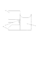
従来、予め所望の形状に加工された金型内に溶融した樹脂材料を射出し、型内で冷却固化後、型を開いて成形品を取り出す方法が、射出成形として広く知られ利用されている。また、製品機能を有する成形品の製品形状部分と溶融樹脂を型内へ注入する成形機の湯口(ノズル部)とは、スプルー、ランナー、ゲートと呼ばれる部分によって通常つながれている。図23は通常用いられているサイドゲートの金型である。48はノズル部射出口、51はゲート、52はランナー、53はスプルー、49は製品形状部、50はエジェクターである。図23に示した通常用いられるサイドゲートタイプの金型では、製品形状部とゲート、ランナー、スプルーが一体のままエジェクターにより型から取り出される。これらスプルー、ランナー、ゲート部は製品機能を持たず、不要な部分である為、成形後製品形状部と切り離された後廃却もしくは、再溶融するなどして再利用されている。しかしながら、スプルー、ランナー部を型から取り出した後、作業者がニッパなどの切断工具を用いてゲート部を切断する為には、人件費がかかる。さらに切断用の自動機については、自動機コストによる部品コストの上昇などのコスト的な問題があった。これらの問題について、ゲート部を小さなピン状態の形状とし、型から取り出す際の型開きの時に、自動的にゲートを切るピンゲート法が利用されている。ピンゲート法ではゲート切断に人を介することなく、又、専用の機械も不要なことから小物の部品などで広く利用されている。しかしながらピンゲート法では金型が3プレートと呼ばれる構造となり、金型構造の複雑化、ランナーボリュームの増加による成形サイクル及び材料コストの増加、型厚の増加、型構造の複雑化等を引き起こすという問題があった。さらに、ピンゲート法の問題を解消する手段として、スプルー、ランナーを不用とするホットランナー法が提案され実用化されている。ホットランナー法では、製品に直接もしくは非常に小さなランナーを用いて成形する為に、廃却する材料は非常に少ない。また、製品に直接ホットランナーのゲートを設置するダイレクトゲートタイプでは、廃材が出ないばかりか、ゲート切断も不要となるという利点を持つ。しかしながら製品形状部に直接ゲートを設けることは製品機能やデザイン上困難なことが多い上に、ホットランナー自身が高価であり、金型コスト上昇を招くとともに、型構造が複雑化する為、メンテナンスの問題を引き起こすという問題があった。 Conventionally, a method in which a molten resin material is injected into a mold that has been processed into a desired shape in advance, and after cooling and solidifying in the mold, the mold is opened and a molded product is taken out is widely known and used as injection molding. . Further, a product shape portion of a molded product having a product function and a sprue (nozzle portion) of a molding machine that injects molten resin into a mold are usually connected by portions called sprue, runner, and gate. FIG. 23 shows a commonly used side gate mold. 48 is a nozzle part injection port, 51 is a gate, 52 is a runner, 53 is a sprue, 49 is a product shape part, 50 is an ejector. In the normally used side gate type mold shown in FIG. 23, the product shape portion, the gate, the runner, and the sprue are integrally removed from the mold by the ejector. Since these sprues, runners, and gates have no product functions and are unnecessary parts, they are reused by being discarded or remelted after being separated from the product shape part after molding. However, after taking out the sprue and runner part from the mold, it takes labor costs for the operator to cut the gate part using a cutting tool such as a nipper. Furthermore, the automatic machine for cutting has a cost problem such as an increase in parts cost due to the automatic machine cost. For these problems, a pin gate method is used in which the gate portion is shaped like a small pin and the gate is automatically cut when the die is opened when the die is removed from the die. The pin gate method is widely used for small parts because it requires no human intervention to cut the gate and does not require a dedicated machine. However, in the pin gate method, the mold has a structure called a three-plate, and there is a problem that the mold structure is complicated, the molding cycle and material cost are increased due to the increase in the runner volume, the mold thickness is increased, the mold structure is complicated, etc. there were. Furthermore, a hot runner method that eliminates the use of sprues and runners has been proposed and put into practical use as a means for solving the problem of the pin gate method. In the hot runner method, since the product is molded directly or using a very small runner, there is very little material to be discarded. In addition, the direct gate type in which the hot runner gate is installed directly on the product has the advantage that not only waste material does not come out, but also the gate cutting becomes unnecessary. However, providing a gate directly in the product shape is often difficult in terms of product function and design, and the hot runner itself is expensive, leading to increased mold costs and complicated mold structure. There was a problem that caused problems.
前記問題を解決する手段として、サイドゲートと呼ばれる型構造が非常にシンプルな方法に加え、型の中にゲートを切断する機能を持たせた、型内ゲート切断法という手法が提案されている。特許文献1によれば、ランナー方向に傾斜面をもつゲートカットピンを設け、そのピンをランナーと鉛直方向に動かすことでゲート部の樹脂をランナー方向へ逆流させ、製品形状部とゲート部を切断することが開示されている。また、特許文献2及び特許文献3においては、CD、光ディスク、DVDディスクなどで行われているディスクゲートに対する型内ゲートカット方法が開示されている。これらによれば、ディスクゲートのコア側に、可動可能なカッターを持つスプルーカットパンチとスプルーカットパンチが作動時に先端が進入可能なカット穴をキャビ側に設けることで、ディスクゲートの型内ゲートカットを行うとしている。また、特許文献4においては、製品側に傾斜面を設けたゲートカットピンを作動させ、ゲート部の樹脂を製品へ押し込むとともに、ゲートを切断する方法が開示されている。さらに、特許文献5においては、金型に設けられたゲートカットピン作動ユニットの開示と、傾斜面をランナー側に設け、ゲート切断後の切断ピンの位置が、キャビティーとランナー双方に接触しているゲートカットピンが開示されている。
しかしながら通常ランナーには製品形状部に生じるひけなどの不良を防止する為に樹脂充填後の保圧と呼ばれる20Mpa〜80Mpaの高い圧力がかかっている。これら従来の金型及び方法において、ゲートカットピンに傾斜面を設け、ゲートカットピンがゲート部の樹脂をランナー側へ逆流させる方法では、保圧完了前もしくは保圧完了直後にゲートカットピンの傾斜面で樹脂をランナー側に戻すのは非常に困難である。また、ランナー側へ樹脂を戻す為にランナーサイズを大きくし、ランナー部樹脂の冷却固化を遅くする必要性があった。しかし、ランナーサイズを大きくすることは、ランナー冷却時間が長くなる為、成形サイクルが長くなり、また、大きくした分の廃却材料が増えるなどの問題があった。さらに、製品形状部に十分な圧力をかけた後冷却中に樹脂が逆流しないようにする目的で、通常ゲートの厚さは製品の厚さよりも薄くし、製品よりもゲート部が早く冷却固化するように設計されるのが常道である。しかしながらゲートカットピンによるゲート切断は、ゲートが固化する前に切断する必要がある為、製品形状部に十分な保圧がかけられないという保圧とゲートカットタイミングとのトレードオフの問題が生じていた。さらに、製品形状部よりもゲートの厚さを大きくした場合には、ランナーを大きくした場合と同様に、成形サイクルが長くなり、廃材料が増えるという問題に加え、製品側のゲートカット面にバリが発生するなどの問題があった。総じて、従来の方法はいずれもゲートカット作動面が製品面の一部であり、切断ピンの摺動面となっている為に、製品面の一部に擦り傷や不連続な凹凸など、ゲート周辺の製品面と同等の品位を保つ事が困難であるという欠点があった。 However, a high pressure of 20 Mpa to 80 Mpa called a holding pressure after resin filling is usually applied to the runner to prevent defects such as sink marks occurring in the product shape portion. In these conventional molds and methods, the gate cut pin is provided with an inclined surface, and the gate cut pin allows the gate portion resin to flow backward to the runner side. It is very difficult to return the resin to the runner side. Moreover, in order to return resin to the runner side, it was necessary to enlarge the runner size and to slow down the cooling and solidification of the runner resin. However, increasing the runner size has problems such as a longer runner cooling time, a longer molding cycle, and an increased amount of discarded material. Furthermore, in order to prevent the resin from flowing backward during cooling after applying sufficient pressure to the product shape part, the thickness of the gate is usually thinner than the product thickness, and the gate part cools and solidifies faster than the product. It is usual to be designed as such. However, gate cutting with the gate cut pin needs to be cut before the gate is solidified, so there is a trade-off problem between holding pressure and gate cutting timing, in which sufficient holding pressure cannot be applied to the product shape part. It was. In addition, when the gate thickness is made larger than the product shape, the molding cycle becomes longer and the amount of waste material increases, as in the case where the runner is made larger. There was a problem such as. In general, in all the conventional methods, the gate cut working surface is a part of the product surface, and the cutting pin sliding surface, so there are scratches and discontinuous irregularities on the part of the product surface. There is a drawback that it is difficult to maintain the same quality as the product side.
前記課題を解決する手段として、本発明の樹脂成形品の製造方法においては、製品形状部を有するキャビティと前記キャビティに樹脂を充填するためのゲート部を有する樹脂成形金型を用いた樹脂成形品の製造方法において、前記ゲート部から前記キャビティを切断する為の切断ピンと、前記切断ピンと前記製品形状部との間に前記ゲート部よりも肉厚が厚く前記ゲート部に連接する圧縮用の圧縮形状部とを設け、前記ゲート部から前記圧縮形状部及び前記製品形状部へ、樹脂を充填する射出工程の後、保圧をかける保圧工程を行ない、前記ゲート部は、前記保圧工程の終了時に前記ゲート部の樹脂が固化する肉厚を有し、前記ゲート部が固化した前記保圧工程の終了後であって、かつ、前記圧縮形状部の樹脂が固化する前に、前記切断ピンの移動により前記圧縮形状部の樹脂を前記ゲート部から切断するとともに前記圧縮形状部の樹脂を前記製品形状部へ移動させて前記製品形状部と一体とすることを特徴とする。 As a means for solving the above-mentioned problem, in the method for producing a resin molded product of the present invention, a resin molded product using a resin molding die having a cavity having a product shape portion and a gate portion for filling the cavity with resin. In the manufacturing method , a cutting pin for cutting the cavity from the gate portion, and a compression shape for compression that is connected to the gate portion and is thicker than the gate portion between the cutting pin and the product shape portion A pressure holding step for applying pressure after the injection step of filling the resin from the gate portion to the compression shape portion and the product shape portion, and the gate portion ends the pressure holding step. sometimes has a thick resin is solidified in the gate portion, even after completion of as the dwelling step of the gate portion is solidified, and, before the resin in the compressed configuration portion is solidified, the cutting pins With cutting the resin in the compressed configuration portion from the gate portion by the movement to move the resin in the compressed configuration unit to the product shape portion, characterized in that integral with the product shape portion.
本発明によれば、ゲート部よりも厚肉の圧縮形状部を設けているので、ゲート切断時にはゲートは冷却固化しており、ランナーへの逆流が起きず、また切断面が製品形状部に無い為、切断による部品外観が悪化することが無い。また、切断個所を製品形状から連続した形状とすることができ、広範な樹脂成形品製造において、生産性が高く、高品位な外観の成形品を得ることが可能となった。 According to the present invention, since the compression-shaped part thicker than the gate part is provided, the gate is cooled and solidified at the time of gate cutting, no backflow to the runner occurs, and the cut surface is not in the product-shaped part. For this reason, the appearance of the parts by cutting does not deteriorate. Further, the cut portion can be changed from the product shape to a continuous shape, and it has become possible to obtain a molded product with high productivity and high-quality appearance in manufacturing a wide range of resin molded products.
図を用いて本発明の樹脂成形金型の構成と動作を説明する。 The configuration and operation of the resin molding die of the present invention will be described with reference to the drawings.
図1は本発明の基本構成を示す実施形態の一例を示しており、金型内に樹脂が充填された直後のゲート付近の概要図である。図1において、1は部品形状部、2は切断ピンと対向しその肉厚が周辺部の部品形状部1より厚く設けてある圧縮用厚肉部、3は圧縮形状部、4は先端にゲートを有するゲート部、5はランナー部、6はピンまたはブロック状の切断ピン、7は製品端面である。部品形状部1と圧縮用厚肉部2で、製品となる形状である製品形状部を構成している。図2は本発明のゲート切断直後の様子を示したものである。 FIG. 1 shows an example of an embodiment showing a basic configuration of the present invention, and is a schematic view of the vicinity of a gate immediately after a mold is filled with resin. In FIG. 1, 1 is a part shape part, 2 is a thick part for compression which is opposed to the cutting pin and is thicker than the part shape part 1 in the peripheral part, 3 is a compression part, 4 is a gate at the tip The gate part 5 has a runner part, 6 is a pin or block-shaped cutting pin, and 7 is a product end face. The part shape part 1 and the thick part 2 for compression constitute a product shape part that is a shape to be a product. FIG. 2 shows a state immediately after the gate is cut according to the present invention.
次に図1及び図2を用いて動作を説明する。切断ピン6と製品形状部との間に前記ゲート部4よりも厚肉の圧縮形状部3を設けている。また圧縮形状部3はゲート部4と連接しており、金型のキャビティー内へ樹脂を充填させる。金型のキャビティーは部品形状部1と圧縮用厚肉部2及び圧縮形状部3とから構成される。製品形状部及び圧縮形状部への樹脂充填直後は図1の状態であり、次の保圧工程に入る。最も肉厚の薄いゲート部4の冷却固化が最も早く、ゲート部4が固化した時点で保圧力が製品形状部に届かなくなる為、保圧工程は終了する。固化とは、樹脂が圧力をかけても動かない状態を言う。保圧工程終了とともに切断ピン6が所定の速度及び適切な圧力により、圧縮形状部3を圧縮しながら上昇を始める。このときゲート部4は既に固化している為ゲート側への樹脂逆流は発生せず、そのため製品形状部の樹脂内圧は、製品形状部の冷却に伴う収縮により引き起こる圧力低下のみの圧力降下しか起こらない。また、圧縮形状部3は、圧縮用厚肉部2と連結しており、ゲート4の肉厚及び部品形状部1の肉厚よりも厚くなっている為、ゲート4が固化後もやわらかい状態にある。ゲート切断面においても圧縮形状部3と繋がる境界面は、圧縮形状部からの伝熱を受けるため、切断可能な柔らかさとなっている。従って切断ピン6が上昇するに従い圧縮形状部3の樹脂は、圧縮用厚肉部2に容易に移動して行き、製品形状と一体となる。切断ピンの移動量は射出成形機のエジェクター動作制御もしくは油圧シリンダーのリミット及び金型内にも受けられたストッパーなどの調整機構により制御されている。それゆえ、図2に示す製品端面7の位置で停止し、圧縮用厚肉部と前記切断ピンの先端部が係合し製品形状部を形成する。その後所定の冷却時間経過後に切断ピン6は元の位置に後退する。製品形状部で成形された成形品を図3に示した。図4はゲート切断後切断ピン6が元の位置に戻った後の型内部の断面図である。図4において製品端面7は、圧縮用厚肉部2の端面と同じ面になっており、切断ピン6の動作により、圧縮形状部は空洞8となっている。また、切断ピン6はTで図示した部分が固定側へ入り込む構造となっている。Tのストロークは後述する固定側ゲート駒のR寸法との関係において適正な値が決められるが、0.5mm〜2.0mm程度が良好である。全ての冷却時間が終了すると、金型が開き、ゲート4と部品形状部1及び圧縮用厚肉部2から構成される製品形状部は各々切り離された状態で取り出され、圧縮形状部3が無い製品形状部である成形品が取り出される。
Next, the operation will be described with reference to FIGS. A
次に図5を用いて部品形状部1と本発明の圧縮形状部3、ゲート部4各々の時間経過に伴う温度変化を説明する。図5において縦軸は温度、横軸は時間を示し、線Aは本発明の圧縮形状部3の温度、線Bは部品形状部1の温度、線Cはゲート部4の温度を示している。また、T1は樹脂温度である。樹脂が型の中に入ると、金型により冷却され樹脂は固化し始める。樹脂温度T1であった樹脂は、各々A,B,Cの軌跡をたどって時間とともに冷却してゆく。樹脂が固化し圧力をかけても動かない(流動しない)温度をNo flow温度といい、t1はゲートがNo flow温度Tcに達した時間である。このときゲートはNo flow温度であるが、ゲートより肉厚の厚いA,Bは流動可能な温度Tb,Taである。また、最も肉厚が厚く、その為温度の高いAがNo flow温度となる時刻t2においては、Bはすでに固化している事になる。従って、本発明におけるゲートカット及び圧縮動作は時刻t1とt2の間に行われることになる。このときCで示したゲート部温度はNo flow温度以下の為逆流することは無く、また、本発明の特徴である圧縮形状部は流動可能で柔らかい為、容易に切断と圧縮を行うことが可能となっている。通常、保圧工程はゲートが冷却するt1以前の時刻に行われ、冷却は樹脂の熱変形温度HDT以下である取り出し温度T3まで行われる事になる。
Next, the temperature change with time passage of each of the component shape portion 1, the
次に本発明の第2の特徴である、金型構造の一部について図6を用いて説明する。図6において10は固定側のゲート駒であり、12は可動側のゲート駒である。固定側ゲート駒には本発明第2の特徴である切断ピン6が作動時に接触する進入口部分にR形状9が設けられている。切断ピンのストロークと部品肉厚により適正な値があるが、通常図6で示したR形状9は、R0.1mm〜R0.5mmである。本発明の実施例においては、樹脂材料:PC/ABS、製品基本肉厚2.0mm、ゲート厚さ1.5mm、ゲートカットピン作動ストローク2.5mm、固定側ゲート駒R0.3mmでゲートカット繰り返し耐久数>100,000であった。その他の実施例を表1に示した。その際用いた切断ピンの先端形状は図8に示す。先端ピンの先端形状は、平面、曲面、及びそれらの組み合わせ形状であってもよい。
Next, a part of the mold structure, which is the second feature of the present invention, will be described with reference to FIG. In FIG. 6, 10 is a fixed-side gate piece, and 12 is a movable-side gate piece. The fixed-side gate piece is provided with an R shape 9 at an entrance portion where the

図7は切断ピンが作動した直後の状態を示しており、切断ピンの固定側ゲート駒への侵入が、R形状9によりスムーズに行われている。一方R形状が無い場合には、切断ピンと固定側ゲート駒のエッジとが干渉し、容易に切断ピンが破損することになる。また、本発明の固定側ゲート駒と切断ピンを内包する可動側ゲート駒は駒同士で勘合位置決めする構造になっているため、両駒間と切断ピンとの相対位置が常に一定となっている。さらに、固定側ゲート駒と切断ピンとの摺動部は、摺動の為のクリアランスが10ミクロン以下になっているために、切断後切断ピンと固定側ゲート駒との間に樹脂が入り込みバリが発生することはない。 FIG. 7 shows a state immediately after the cutting pin is actuated, and the cutting pin smoothly enters the fixed-side gate piece by the R shape 9. On the other hand, when there is no R shape, the cutting pin and the edge of the fixed side gate piece interfere with each other, and the cutting pin is easily damaged. In addition, since the movable side gate piece including the fixed side gate piece and the cutting pin according to the present invention has a structure in which the pieces are fitted and positioned, the relative position between the two pieces and the cutting pin is always constant. Furthermore, since the sliding clearance between the fixed-side gate piece and the cutting pin has a sliding clearance of 10 microns or less, the resin enters between the cutting pin and the fixed-side gate piece after cutting to generate burrs. Never do.
図9は製品端面がテーパー状になっている部分へ本発明を応用した事例であり、例えばプリンター、複写機、FAX、スキャナー及びそれらの複合機等の筐体等に使用されている樹脂成形品に用いた実施例である。14は部品形状部、15は圧縮形状部、16はゲート部である。圧縮形状部15を設け切断ピンが圧縮形状部を圧縮しつつゲート16を切断する。切断ピンの動作は、前記説明したように、圧縮形状部の方が部品テーパー部及びゲート部よりも肉厚が厚い為、冷却固化が遅れることから、スムーズに動作した。
FIG. 9 is an example in which the present invention is applied to a portion where the end face of the product is tapered. For example, a resin molded product used in a housing of a printer, a copying machine, a FAX, a scanner, or a complex machine thereof. It is the Example used for.
図10は図9で示した実施例のゲート切断後の切断面付近である。18は切断ピンの移動により作られた面、17は切断ピンと対向する圧縮用厚肉部である。切断ピンの適切な作動タイミング、速度、位置の制御により、面18と製品端面とはほぼ同位置にあり、ゲートカット後の部品端面について、非常にきれいな表面と外観を得ることが出来た。
FIG. 10 shows the vicinity of the cut surface after gate cutting in the embodiment shown in FIG.
図11は本発明の他の実施例であり、19は切断ピンの移動により作られた面、20は製品端面である。本実施例は、製品機能上製品端面よりもわずかでも出っ張ることが禁止されている場合に、切断ピンの最終ストローク位置をわずかながら製品端面よりも製品内部へ移動したものであり、他の実施例と同様に、良好な切断面と圧縮面を得ることが出来た。 FIG. 11 shows another embodiment of the present invention, in which 19 is a surface made by moving a cutting pin, and 20 is a product end surface. In this embodiment, when it is prohibited to protrude even slightly from the product end face due to the product function, the final stroke position of the cutting pin is slightly moved from the product end face to the inside of the product. In the same manner as above, a good cut surface and compression surface could be obtained.
図12は本発明の他の実施例であり、21は製品機能を兼ねた圧縮用厚肉部、22は製品端面、23は切断ピンの移動により作られた面である。ゲート近傍の製品内壁部に位置決め等の機能部がある場合、その位置決め部を他の製品部よりも厚肉とし、厚肉部に本発明のゲート切断及び圧縮機構を設けることで、良好なゲート切断とゲート部外観を得ることができた。実施例では内壁の位置決め部位が製品端面まで必要なことから、ゲート切断ピンの圧縮面を厚肉部全ての肉厚とせずに、製品肉厚と同じ肉厚とした。 FIG. 12 shows another embodiment of the present invention, in which 21 is a thick part for compression which also functions as a product, 22 is a product end surface, and 23 is a surface made by moving a cutting pin. When there is a functional part such as positioning on the product inner wall near the gate, the positioning part is thicker than other product parts, and the gate cutting and compression mechanism of the present invention is provided in the thick part, so that a good gate Cutting and gate part appearance could be obtained. In the embodiment, since the positioning part of the inner wall is required up to the product end face, the thickness of the compression surface of the gate cutting pin is not the same as that of the thick part, but the same thickness as the product thickness.
図13乃至図14は本発明をCD,DVD,光磁気ディスク等の円盤状成形品に応用した例である。図13において、24は円盤状成形品である。図14は円盤状成形品に本発明を用いたゲート近傍の拡大図であり、25はスプルー、26はディスク状ランナー、27は本発明の円周上に連続で設けられた厚肉部兼圧縮部である。切断ピンはリング状をしており、切断ピンの動作により圧縮部27を圧縮すると同時にディスク状ランナー26と分離する事が出来た。図15はゲート切断後のゲート近傍部であり、28は切断ピンの移動により作られた面である。
FIGS. 13 to 14 show examples in which the present invention is applied to a disk-shaped molded product such as a CD, DVD, or magneto-optical disk. In FIG. 13, 24 is a disk-shaped molded product. FIG. 14 is an enlarged view of the vicinity of a gate using the present invention in a disk-shaped molded product, 25 is a sprue, 26 is a disk-shaped runner, and 27 is a thick portion and compression provided continuously on the circumference of the present invention. Part. The cutting pin has a ring shape, and the
図16乃至図17は、本発明を樹脂製の光学レンズ成形に用いた実施例である。図16において29は光学機能レンズ部、30はレンズを組込み時に鏡筒と勘合するフランジ部、33は本発明の厚肉部、31はゲート部、32はランナーである。切断ピンの作動によりゲート部31とフランジ部30とが分離される。図17はゲート切断後の製品であり、34は切断ピンの作動により作られた面である。面は非常にスムーズであり、通常ゲート切断後の切断面が荒れた場合、光が散乱し、光学機能に悪影響を与えることから、熱したニッパなどを用いて作業者が切断していたが、本発明を実施例のように行うことで、安定して滑らかな面を得ることが出来た。
16 to 17 show an embodiment in which the present invention is used for molding a resin optical lens. In FIG. 16, 29 is an optical function lens part, 30 is a flange part which engages with a lens barrel when the lens is assembled, 33 is a thick part of the present invention, 31 is a gate part, and 32 is a runner. The
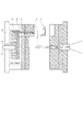
図18乃至図20は本発明のプロセスを示している。図18において、部品形状部1及び圧縮用厚肉部2とランナー37とはゲート4と圧縮形状部3とを介してつながっている。また、ランナー37は、スプルー36を介して射出成形機のノズル35とつながっている。図18において39は固定側型板、40は可動側型板であり、切断ピン6は切断ピン作動プレート41に固定されており、作動時に固定側ゲート駒44と可動側ゲート駒45とに接している。エジェクターピン38は、エジェクタープレート42に固定されている。43は、射出成形機のエジェクターロッドである。図18において本発明の特徴である切断ピンは、エジェクタープレートと並列に設けられた切断ピン作動プレート41により動作することになる。図19は、本発明のゲート切断及び圧縮を行った直後の状態を示している。射出工程及び保圧工程完了後、成形機の作動用ロッドであるエジェクターロッド43が予め設定された移動量と速度により動き、切断ピン6と連結している切断ピン作動プレート41を動かす。この動作により、切断ピン6は、可動側ゲート駒45内を摺動しつつ圧縮形状部3を製品形状部方向へ圧縮し始め、圧縮しつつゲート4を切断し、固定側ゲート駒内に侵入し、完全にゲートを切断するとともに、圧縮形状部3を製品形状部内へ押し込む。本発明のこれら動作により、型内で、製品形状部とゲート部とが完全に分離することが可能となった。
18-20 illustrate the process of the present invention. In FIG. 18, the component shape portion 1, the compression thick portion 2 and the
図20は、製品取出状態を示した図である。図19で説明したように、製品形状部とゲート部4とは型内で分離される。型が開きエジェクターロット43が作動(前進)すると、切断ピン作動プレートがさらに前進することで切断ピン作動プレートと連結プレート47で連結されたエジェクタープレート46が前進する。それによってエジェクター38が作動し、製品形状部(部品形状部1及び圧縮用厚肉部2)を型から排出する。切断ピン作動プレートとエジェクタープレートとを連結する連結プレートはストローク調整機構を持ち、切断ピン作動ストロークとエジェクター作動とのタイミングを調整することが可能である。
FIG. 20 is a diagram showing a product removal state. As described in FIG. 19, the product shape portion and the gate portion 4 are separated in the mold. When the mold is opened and the
図21には、本発明の連結プレートの調整機構の一例を示した。切断ピン作動プレート41は、連結ピン61により連結プレート47に連結する。エジェクタープレート46は、調整機構54が調整機構取り付け部材63によって取り付けられ、さらに連結ピン62によって調整機構54を連結プレート47に連結する。連結ピン62は調整機構54上を移動自在に取り付けられ、切断ピン作動プレート41が大きく前進すると、連結ピン62が調整機構取り付け部材63に突き当たり、エジェクタープレート46を切断ピン作動プレート41と所定間隔を保って前進するように構成されている。よって調整機構54の長さを調整することによりストローク及びタイミングが調整可能となる。
FIG. 21 shows an example of the connection plate adjusting mechanism of the present invention. The cutting
図22は切断ピンの駆動源として油圧シリンダーを金型内へ装備した実施例である。図において55は油圧シリンダーであり、切断ピン6と連結している。油圧シリンダーは外部の油圧発生源(油圧ポンプ)とつながっており、射出成形機からの信号により動作を行う。
FIG. 22 shows an embodiment in which a hydraulic cylinder is installed in the mold as a drive source for the cutting pin. In the figure, 55 is a hydraulic cylinder, which is connected to the
本発明では、新たにゲート部よりも厚肉の製品端面からゲートへ繋がるダミー形状である圧縮用の圧縮形状部及び製品形状部に圧縮用厚肉部を設け、切断用ピンの先端形状を圧縮用厚肉部と係合し連続するなだらかな形状としている。また切断ストロークがゲート厚みより大きく、切断後の切断ピン先端がゲートの金型キャビティー側端面よりもさらにキャビティー側に突出し、製品形状と同一面まで及ぶように構成されている。従って、ゲート切断時にゲートは冷却固化し、ランナーへの逆流が起きないとともに、切断面が製品形状部に無い為、切断による部品外観が悪化することは無く切断個所は製品形状から連続したものとなる。さらには、ゲートを挟み込むように固定側と可動側に、ゲート切断駒を設け、切断ピンが前進して摺動する固定側のゲート切断駒エッジに面取り加工を施こすように構成されている。従って、ゲート切断ピンが樹脂圧の影響や、度重なる切断時の応力により変形し、固定側の駒とカジリ等の破損を生じることがない。また、切断ピンは切断ピン作動装置もしくは金型プレートに転結されており、金型プレートは所定の作動範囲を超えた状態では、エジェクタープレートとともに作動する構造になっている。従って、射出成形機の型閉中エジェクター作動モードなどにより、通常のエジェクターを作動させるのと同様な操作で制御可能である。 In the present invention, a compression compression shape portion that is a dummy shape that is connected to the gate from the product end surface that is thicker than the gate portion, and a compression thick portion are provided in the product shape portion, and the tip shape of the cutting pin is compressed. It has a gentle shape that engages with the thick part for continuous use. Further, the cutting stroke is larger than the gate thickness, and the cutting pin tip after cutting protrudes further toward the cavity side than the end surface on the mold cavity side of the gate and extends to the same surface as the product shape. Therefore, when the gate is cut, the gate is cooled and solidified, and no back flow to the runner occurs, and the cut surface is not in the product shape part, so that the appearance of parts due to cutting does not deteriorate and the cut part is continuous from the product shape. Become. Further, gate cutting pieces are provided on the fixed side and the movable side so as to sandwich the gate, and chamfering is performed on the edge of the gate cutting piece on the fixed side where the cutting pin advances and slides. Therefore, the gate cutting pin is not deformed by the influence of the resin pressure or the stress at the time of repeated cutting, and the fixed side piece and galling are not damaged. Further, the cutting pin is rolled to a cutting pin operating device or a mold plate, and the mold plate is configured to operate together with the ejector plate in a state where the predetermined operating range is exceeded. Therefore, it can be controlled by the same operation as that for operating a normal ejector by the ejector operating mode during mold closing of the injection molding machine.
本発明により、プリンターや複写機などの事務機器、カメラ、ビデオカメラなどの光学機器、あるいは樹脂製部品を使用する車など、広範な樹脂成形品製造において、生産性が高く、高品位な外観の成形品を得ることが可能となった。 According to the present invention, high productivity and high quality appearance can be achieved in a wide range of resin molded product manufacturing such as office equipment such as printers and copiers, optical equipment such as cameras and video cameras, or cars using resin parts. It became possible to obtain molded products.
以上説明したように、本発明は、樹脂材料を溶融し金型内に射出し樹脂製成形品を得る樹脂加工産業において、生産性を向上させるとともに、品質を向上することに大きく貢献する。また、本発明の応用展開は、樹脂の成形のみならずセラミックスの射出成形、アルミダイキャスト、シート成形、ゴムの成形加工などへも可能である。 As described above, the present invention greatly contributes to improving productivity and improving quality in the resin processing industry in which a resin material is melted and injected into a mold to obtain a resin molded product. Further, the application of the present invention can be applied not only to resin molding, but also to ceramic injection molding, aluminum die casting, sheet molding, rubber molding, and the like.
1 部品形状部
2 圧縮用厚肉部
3 圧縮形状部
4 ゲート部
5 ランナー部
6 切断ピン
7 製品端面
8 空洞部
9 R形状
10、44 固定側ゲート駒
12、45 可動側ゲート駒
41 切断ピン作動プレート
42 エジェクタープレート
47 連結プレート
54 調整機構
DESCRIPTION OF SYMBOLS 1 Component shape part 2 Thick part for
Claims (3)
前記ゲート部から前記キャビティを切断する為の切断ピンと、前記切断ピンと前記製品形状部との間に前記ゲート部よりも肉厚が厚く前記ゲート部に連接する圧縮用の圧縮形状部とを設け、
前記ゲート部から前記圧縮形状部及び前記製品形状部へ、樹脂を充填する射出工程の後、保圧をかける保圧工程を行ない、
前記ゲート部は、前記保圧工程の終了時に前記ゲート部の樹脂が固化する肉厚を有し、
前記ゲート部が固化した前記保圧工程の終了後であって、かつ、前記圧縮形状部の樹脂が固化する前に、前記切断ピンの移動により前記圧縮形状部の樹脂を前記ゲート部から切断するとともに前記圧縮形状部の樹脂を前記製品形状部へ移動させて前記製品形状部と一体とすることを特徴とする樹脂成形品の製造方法。 In a method for producing a resin molded product using a resin molding die having a cavity having a product shape portion and a gate portion for filling the cavity with resin,
A cutting pin for cutting the cavity from the gate portion, and a compression shape portion for compression connected to the gate portion having a thickness thicker than the gate portion between the cutting pin and the product shape portion,
After the injection step of filling the resin from the gate portion to the compression shape portion and the product shape portion , a pressure holding step of applying pressure is performed,
The gate portion has a thickness at which the resin of the gate portion is solidified at the end of the pressure holding step,
After the pressure holding step when the gate portion is solidified and before the resin of the compression shape portion is solidified, the resin of the compression shape portion is cut from the gate portion by the movement of the cutting pin. In addition, a method of manufacturing a resin molded product, wherein the resin of the compression-shaped portion is moved to the product-shaped portion and integrated with the product-shaped portion.
前記圧縮用厚肉部は、前記圧縮形状部と同じ肉厚であって、前記部品形状部より肉厚が厚いことを特徴とする請求項1記載の樹脂成形品の製造方法。 The product shape part is composed of a compression thick part connected to the compression shape part, and a part shape part connected to the compression thick part and being a part other than the compression thick part ,
The method for manufacturing a resin molded product according to claim 1 , wherein the thick portion for compression has the same thickness as the compression shape portion and is thicker than the component shape portion.
Priority Applications (4)
| Application Number | Priority Date | Filing Date | Title |
|---|---|---|---|
| JP2006297643A JP4963402B2 (en) | 2006-11-01 | 2006-11-01 | Manufacturing method of resin molded products |
| PCT/JP2007/071273 WO2008053946A1 (en) | 2006-11-01 | 2007-10-25 | Injection molding process, resin molded product and mold |
| CN200780040895.XA CN101535027B (en) | 2006-11-01 | 2007-10-25 | Injection molding process, resin molded product and mold |
| US12/441,297 US7837915B2 (en) | 2006-11-01 | 2007-10-25 | Injection molding process, resin molded product and mold |
Applications Claiming Priority (1)
| Application Number | Priority Date | Filing Date | Title |
|---|---|---|---|
| JP2006297643A JP4963402B2 (en) | 2006-11-01 | 2006-11-01 | Manufacturing method of resin molded products |
Publications (3)
| Publication Number | Publication Date |
|---|---|
| JP2008114408A JP2008114408A (en) | 2008-05-22 |
| JP2008114408A5 JP2008114408A5 (en) | 2009-12-17 |
| JP4963402B2 true JP4963402B2 (en) | 2012-06-27 |
Family
ID=39344286
Family Applications (1)
| Application Number | Title | Priority Date | Filing Date |
|---|---|---|---|
| JP2006297643A Expired - Fee Related JP4963402B2 (en) | 2006-11-01 | 2006-11-01 | Manufacturing method of resin molded products |
Country Status (4)
| Country | Link |
|---|---|
| US (1) | US7837915B2 (en) |
| JP (1) | JP4963402B2 (en) |
| CN (1) | CN101535027B (en) |
| WO (1) | WO2008053946A1 (en) |
Families Citing this family (11)
| Publication number | Priority date | Publication date | Assignee | Title |
|---|---|---|---|---|
| JP4292224B2 (en) | 2007-12-14 | 2009-07-08 | 株式会社東芝 | Manufacturing method of molds and castings |
| JP4725595B2 (en) | 2008-04-24 | 2011-07-13 | ソニー株式会社 | Video processing apparatus, video processing method, program, and recording medium |
| JP5653204B2 (en) * | 2010-12-24 | 2015-01-14 | 矢崎総業株式会社 | Molding method for automotive interior illumination lens and interior illumination lens |
| US20130044100A1 (en) * | 2011-08-17 | 2013-02-21 | Samsung Electronics Co. Ltd. | Portable device with integrated user interface for microfluidic display |
| CN102990876A (en) * | 2011-09-13 | 2013-03-27 | 鸿富锦精密工业(深圳)有限公司 | Injection molded part production system and method thereof |
| JP6700702B2 (en) * | 2015-09-30 | 2020-05-27 | キヤノン株式会社 | Injection mold, method for manufacturing molded product, method for manufacturing dome cover, and mold component |
| US20180178418A1 (en) * | 2016-12-22 | 2018-06-28 | Canon Kabushiki Kaisha | Resin molding, printer, and method for manufacturing resin molding |
| CN106626281A (en) * | 2016-12-28 | 2017-05-10 | 深圳天珑无线科技有限公司 | Lifter of injection mold and injection mold |
| JP7034725B2 (en) * | 2018-01-17 | 2022-03-14 | キヤノン株式会社 | Manufacturing method of dome type cover, camera, injection molding type, and dome type cover |
| CN108407193B (en) * | 2018-05-04 | 2023-11-10 | 宁波尚唯汽车饰件有限公司 | Punching device for sound insulation pad of automobile |
| JP7287322B2 (en) * | 2020-03-25 | 2023-06-06 | トヨタ自動車株式会社 | METHOD AND APPARATUS FOR MANUFACTURING FIBER REINFORCED RESIN MOLDED PRODUCTS |
Family Cites Families (18)
| Publication number | Priority date | Publication date | Assignee | Title |
|---|---|---|---|---|
| JPS6194733A (en) * | 1984-10-15 | 1986-05-13 | Hidemitsu Otsuka | Gateless mold for injection molding |
| JPS6211621A (en) | 1985-07-10 | 1987-01-20 | Canon Inc | Injection molding machine |
| JP3041975B2 (en) | 1991-01-23 | 2000-05-15 | 市光工業株式会社 | Gate cutting method in mold for thermoplastic injection molding |
| JPH04280824A (en) | 1991-03-06 | 1992-10-06 | Canon Inc | Production device of optical element |
| JP2966707B2 (en) * | 1993-09-14 | 1999-10-25 | 株式会社小糸製作所 | Injection molding method and structure of injection mold |
| JPH08323827A (en) * | 1995-05-30 | 1996-12-10 | Nippon G Ii Plast Kk | Resin molding method and apparatus |
| JPH09174621A (en) | 1995-12-21 | 1997-07-08 | Fanuc Ltd | Structure of sprue part ejector pin in die gate cutting |
| JPH09277321A (en) * | 1996-04-15 | 1997-10-28 | Sony Corp | Equipment and method for injection molding |
| JPH1058490A (en) * | 1996-08-27 | 1998-03-03 | Sakura Plast:Kk | Mold for injection molding |
| JP3207784B2 (en) | 1997-05-27 | 2001-09-10 | 株式会社精工技研 | Disk molding die |
| JP3178659B2 (en) | 1997-06-06 | 2001-06-25 | 株式会社精工技研 | Disc molding die |
| JP3934775B2 (en) * | 1998-02-25 | 2007-06-20 | 富士フイルム株式会社 | Injection molding method and injection mold |
| JP2000108180A (en) * | 1998-10-06 | 2000-04-18 | Toppan Printing Co Ltd | Mold for injection compression molding and method therefor |
| EP1225022A1 (en) | 2000-12-22 | 2002-07-24 | Fisa Corporation | In-mold gate opening and closing mechanism and metal mold for injection molding |
| JP2002326257A (en) * | 2001-05-07 | 2002-11-12 | Mitsubishi Electric Corp | Injection molding machine for seal member |
| JP4721385B2 (en) | 2001-07-02 | 2011-07-13 | キヤノン株式会社 | Method and apparatus for supplying resin material to injection molding machine |
| JP2004090305A (en) | 2002-08-30 | 2004-03-25 | Canon Inc | Injection mold |
| US7722792B2 (en) | 2007-02-05 | 2010-05-25 | Canon Kabushiki Kaisha | Injection mold and partial compression molding method |
-
2006
- 2006-11-01 JP JP2006297643A patent/JP4963402B2/en not_active Expired - Fee Related
-
2007
- 2007-10-25 WO PCT/JP2007/071273 patent/WO2008053946A1/en active Application Filing
- 2007-10-25 US US12/441,297 patent/US7837915B2/en not_active Expired - Fee Related
- 2007-10-25 CN CN200780040895.XA patent/CN101535027B/en not_active Expired - Fee Related
Also Published As
| Publication number | Publication date |
|---|---|
| WO2008053946A1 (en) | 2008-05-08 |
| JP2008114408A (en) | 2008-05-22 |
| CN101535027A (en) | 2009-09-16 |
| US7837915B2 (en) | 2010-11-23 |
| CN101535027B (en) | 2012-04-04 |
| US20100047500A1 (en) | 2010-02-25 |
Similar Documents
| Publication | Publication Date | Title |
|---|---|---|
| JP4963402B2 (en) | Manufacturing method of resin molded products | |
| JP4087818B2 (en) | Method for forming thick light guide plate | |
| JPH0712632B2 (en) | In-mold vibration finishing removal method | |
| JP2001009878A (en) | Injection mold | |
| JP3462377B2 (en) | Die casting method and die casting apparatus | |
| JP3752160B2 (en) | Injection molding method of composite molded product and injection mold | |
| JP4869990B2 (en) | Injection mold and injection molding method using the same | |
| JP4021962B2 (en) | Polygon mirror, injection molding method thereof and injection mold | |
| JP6134776B1 (en) | Die casting mold | |
| JPH069826Y2 (en) | Backflow prevention device for injection compression molding dies | |
| JP2001277315A (en) | Method for injection compression molding and injection compression molding apparatus for executing the method | |
| JPS6283121A (en) | Injection molding apparatus for concave lens | |
| TWI774551B (en) | Sprue cut-off plastic lens molding device | |
| JPH0994856A (en) | Mold for injection molding | |
| US20210069952A1 (en) | Method for producing an optical lens and optical lens produced by said method | |
| JP2966707B2 (en) | Injection molding method and structure of injection mold | |
| JP3701444B2 (en) | Injection molding method and injection mold | |
| JPH0422614A (en) | Method for molding plastic lens | |
| JP3974544B2 (en) | Mold equipment | |
| JPH06305746A (en) | Mold for forming optical glass lens | |
| JPH11353720A (en) | Production of optical disk substrate | |
| JPH06305745A (en) | Mold for forming optical glass lens | |
| JP2005297466A (en) | Plastic mold and plastic molding method | |
| JPH09174631A (en) | Injection molding method | |
| JPS63114609A (en) | Apparatus and method for injection-molding disc |
Legal Events
| Date | Code | Title | Description |
|---|---|---|---|
| A521 | Request for written amendment filed |
Free format text: JAPANESE INTERMEDIATE CODE: A523 Effective date: 20091102 |
|
| A621 | Written request for application examination |
Free format text: JAPANESE INTERMEDIATE CODE: A621 Effective date: 20091102 |
|
| RD04 | Notification of resignation of power of attorney |
Free format text: JAPANESE INTERMEDIATE CODE: A7424 Effective date: 20100201 |
|
| RD01 | Notification of change of attorney |
Free format text: JAPANESE INTERMEDIATE CODE: A7421 Effective date: 20100630 |
|
| A131 | Notification of reasons for refusal |
Free format text: JAPANESE INTERMEDIATE CODE: A131 Effective date: 20111018 |
|
| A521 | Request for written amendment filed |
Free format text: JAPANESE INTERMEDIATE CODE: A523 Effective date: 20111219 |
|
| TRDD | Decision of grant or rejection written | ||
| A01 | Written decision to grant a patent or to grant a registration (utility model) |
Free format text: JAPANESE INTERMEDIATE CODE: A01 Effective date: 20120321 |
|
| A01 | Written decision to grant a patent or to grant a registration (utility model) |
Free format text: JAPANESE INTERMEDIATE CODE: A01 |
|
| A61 | First payment of annual fees (during grant procedure) |
Free format text: JAPANESE INTERMEDIATE CODE: A61 Effective date: 20120323 |
|
| R151 | Written notification of patent or utility model registration |
Ref document number: 4963402 Country of ref document: JP Free format text: JAPANESE INTERMEDIATE CODE: R151 |
|
| FPAY | Renewal fee payment (event date is renewal date of database) |
Free format text: PAYMENT UNTIL: 20150406 Year of fee payment: 3 |
|
| LAPS | Cancellation because of no payment of annual fees |