JP4960602B2 - Bright field light source for fluorescence observation and surgical microscope equipped with the same - Google Patents
Bright field light source for fluorescence observation and surgical microscope equipped with the same Download PDFInfo
- Publication number
- JP4960602B2 JP4960602B2 JP2005119082A JP2005119082A JP4960602B2 JP 4960602 B2 JP4960602 B2 JP 4960602B2 JP 2005119082 A JP2005119082 A JP 2005119082A JP 2005119082 A JP2005119082 A JP 2005119082A JP 4960602 B2 JP4960602 B2 JP 4960602B2
- Authority
- JP
- Japan
- Prior art keywords
- light source
- surgical microscope
- bright field
- affected area
- field light
- Prior art date
- Legal status (The legal status is an assumption and is not a legal conclusion. Google has not performed a legal analysis and makes no representation as to the accuracy of the status listed.)
- Expired - Fee Related
Links
- 230000002093 peripheral effect Effects 0.000 claims description 24
- 230000005284 excitation Effects 0.000 claims description 19
- 239000004065 semiconductor Substances 0.000 claims description 12
- 230000001678 irradiating effect Effects 0.000 claims description 4
- 239000003504 photosensitizing agent Substances 0.000 claims 1
- 238000005286 illumination Methods 0.000 description 8
- 239000000126 substance Substances 0.000 description 6
- 230000000007 visual effect Effects 0.000 description 4
- 238000012423 maintenance Methods 0.000 description 3
- 238000007796 conventional method Methods 0.000 description 2
- 208000003174 Brain Neoplasms Diseases 0.000 description 1
- VSEIDZLLWQQJGK-CHOZPQDDSA-N CCC1=C(C)C2=N\C\1=C/C1=C(C)C(C(O)=O)=C(N1)\C(CC(=O)N[C@@H](CC(O)=O)C(O)=O)=C1/N=C(/C=C3\N/C(=C\2)C(C=C)=C3C)[C@@H](C)[C@@H]1CCC(O)=O Chemical compound CCC1=C(C)C2=N\C\1=C/C1=C(C)C(C(O)=O)=C(N1)\C(CC(=O)N[C@@H](CC(O)=O)C(O)=O)=C1/N=C(/C=C3\N/C(=C\2)C(C=C)=C3C)[C@@H](C)[C@@H]1CCC(O)=O VSEIDZLLWQQJGK-CHOZPQDDSA-N 0.000 description 1
- 206010028980 Neoplasm Diseases 0.000 description 1
- 210000004556 brain Anatomy 0.000 description 1
- 238000010586 diagram Methods 0.000 description 1
- 239000000835 fiber Substances 0.000 description 1
- 229910052736 halogen Inorganic materials 0.000 description 1
- 150000002367 halogens Chemical class 0.000 description 1
- 230000002452 interceptive effect Effects 0.000 description 1
- 239000000463 material Substances 0.000 description 1
- 238000001356 surgical procedure Methods 0.000 description 1
- 229950010924 talaporfin Drugs 0.000 description 1
- 229910052724 xenon Inorganic materials 0.000 description 1
- FHNFHKCVQCLJFQ-UHFFFAOYSA-N xenon atom Chemical compound [Xe] FHNFHKCVQCLJFQ-UHFFFAOYSA-N 0.000 description 1
Images


Classifications
-
- G—PHYSICS
- G02—OPTICS
- G02B—OPTICAL ELEMENTS, SYSTEMS OR APPARATUS
- G02B21/00—Microscopes
- G02B21/16—Microscopes adapted for ultraviolet illumination ; Fluorescence microscopes
-
- A—HUMAN NECESSITIES
- A61—MEDICAL OR VETERINARY SCIENCE; HYGIENE
- A61B—DIAGNOSIS; SURGERY; IDENTIFICATION
- A61B90/00—Instruments, implements or accessories specially adapted for surgery or diagnosis and not covered by any of the groups A61B1/00 - A61B50/00, e.g. for luxation treatment or for protecting wound edges
- A61B90/30—Devices for illuminating a surgical field, the devices having an interrelation with other surgical devices or with a surgical procedure
-
- G—PHYSICS
- G01—MEASURING; TESTING
- G01N—INVESTIGATING OR ANALYSING MATERIALS BY DETERMINING THEIR CHEMICAL OR PHYSICAL PROPERTIES
- G01N21/00—Investigating or analysing materials by the use of optical means, i.e. using sub-millimetre waves, infrared, visible or ultraviolet light
- G01N21/62—Systems in which the material investigated is excited whereby it emits light or causes a change in wavelength of the incident light
- G01N21/63—Systems in which the material investigated is excited whereby it emits light or causes a change in wavelength of the incident light optically excited
- G01N21/64—Fluorescence; Phosphorescence
- G01N21/645—Specially adapted constructive features of fluorimeters
- G01N21/6456—Spatial resolved fluorescence measurements; Imaging
- G01N21/6458—Fluorescence microscopy
-
- A—HUMAN NECESSITIES
- A61—MEDICAL OR VETERINARY SCIENCE; HYGIENE
- A61B—DIAGNOSIS; SURGERY; IDENTIFICATION
- A61B90/00—Instruments, implements or accessories specially adapted for surgery or diagnosis and not covered by any of the groups A61B1/00 - A61B50/00, e.g. for luxation treatment or for protecting wound edges
- A61B90/30—Devices for illuminating a surgical field, the devices having an interrelation with other surgical devices or with a surgical procedure
- A61B2090/309—Devices for illuminating a surgical field, the devices having an interrelation with other surgical devices or with a surgical procedure using white LEDs
-
- A—HUMAN NECESSITIES
- A61—MEDICAL OR VETERINARY SCIENCE; HYGIENE
- A61B—DIAGNOSIS; SURGERY; IDENTIFICATION
- A61B5/00—Measuring for diagnostic purposes; Identification of persons
- A61B5/0059—Measuring for diagnostic purposes; Identification of persons using light, e.g. diagnosis by transillumination, diascopy, fluorescence
-
- A—HUMAN NECESSITIES
- A61—MEDICAL OR VETERINARY SCIENCE; HYGIENE
- A61B—DIAGNOSIS; SURGERY; IDENTIFICATION
- A61B90/00—Instruments, implements or accessories specially adapted for surgery or diagnosis and not covered by any of the groups A61B1/00 - A61B50/00, e.g. for luxation treatment or for protecting wound edges
- A61B90/20—Surgical microscopes characterised by non-optical aspects
-
- G—PHYSICS
- G01—MEASURING; TESTING
- G01N—INVESTIGATING OR ANALYSING MATERIALS BY DETERMINING THEIR CHEMICAL OR PHYSICAL PROPERTIES
- G01N2201/00—Features of devices classified in G01N21/00
- G01N2201/06—Illumination; Optics
- G01N2201/062—LED's
Landscapes
- Health & Medical Sciences (AREA)
- Life Sciences & Earth Sciences (AREA)
- Physics & Mathematics (AREA)
- Pathology (AREA)
- Surgery (AREA)
- Analytical Chemistry (AREA)
- Chemical & Material Sciences (AREA)
- General Health & Medical Sciences (AREA)
- General Physics & Mathematics (AREA)
- Nuclear Medicine, Radiotherapy & Molecular Imaging (AREA)
- Medical Informatics (AREA)
- Oral & Maxillofacial Surgery (AREA)
- Biochemistry (AREA)
- Engineering & Computer Science (AREA)
- Biomedical Technology (AREA)
- Heart & Thoracic Surgery (AREA)
- Immunology (AREA)
- Molecular Biology (AREA)
- Animal Behavior & Ethology (AREA)
- Public Health (AREA)
- Veterinary Medicine (AREA)
- Optics & Photonics (AREA)
- Microscoopes, Condenser (AREA)
Description
本発明は、蛍光観察時の明視野光源及びそれを搭載した手術顕微鏡に関するものである。 The present invention relates to a bright field light source and surgical microscope equipped with it during fluorescence observation.
例えば脳外科手術において、光感受性物質を患者に投与し、腫瘍等の患部への集積が進んだ段階で、手術室内の照明を消して暗くし、その光感受性物質を励起できる波長の励起光(例えばレーザー)を照射する。すると光感受性物質を集積した患部だけから蛍光が放射されるため、蛍光を発する患部を、励起光の波長をカットするノッチフィルターを介して手術顕微により観察することができる。 For example, in brain surgery, a photosensitive substance is administered to a patient, and when it accumulates in an affected area such as a tumor, the illumination in the operating room is turned off to darken the excitation light having a wavelength that can excite the photosensitive substance (for example, Laser). Then, since fluorescence is emitted only from the affected area where the photosensitive substance is accumulated, the affected area that emits fluorescence can be observed by a surgical microscope through a notch filter that cuts the wavelength of the excitation light.
励起光の波長をノッチフィルターでカットするのは、その波長範囲の光の強度が強く、蛍光観察の邪魔になるからである。手術顕微鏡における視野内では、患部だけが暗視野において蛍光により浮かび上がった状態で観察でき、その周辺部は真っ暗である。周辺部を観察するには、患部への励起光の照射を停止し、手術室の照明を点灯して明るくした状態で通常の観察をする必要がある。
しかしながら、このような従来の技術にあっては、蛍光状態の患部の周辺部が暗いため、周辺部を観察するには励起光を停止して、手術室内の照明をその都度点灯する必要があり、煩わしかった。また、蛍光状態の患部と周辺部を同時に観察することができず、不便であった。 However, in such a conventional technique, since the peripheral part of the affected part in the fluorescent state is dark, in order to observe the peripheral part, it is necessary to stop the excitation light and turn on the illumination in the operating room each time. It was annoying. Further, the affected part and the peripheral part in the fluorescent state could not be observed at the same time, which was inconvenient.
本発明は、このような従来の技術に着目してなされたものであり、蛍光状態の患部と、その周辺部の同時観察を可能する明視野光源及びそれを搭載した手術顕微鏡を提供するものである。 The present invention has been made paying attention to such a conventional technique, and provides a bright-field light source capable of simultaneously observing an affected area in a fluorescent state and its peripheral area, and a surgical microscope equipped with the bright-field light source. is there.
請求項1記載の発明は、光感受性物質を集積させた患部に励起光を照射して蛍光を発生させる半導体レーザー照射装置と、前記患部及び周辺部を観察する際に前記励起光の反射光をカットすると共に前記蛍光を通過させるノッチフィルターと、観察光の取入口の周囲に位置し、前記患部及び周辺部を照明する明視野光源とを備え、前記明視野光源は、前記患部の蛍光に相当する波長領域が、他の領域よりも相対的に低い発光強度を有するか、またはフィルターによりカットされた可視光を発することを特徴とする手術顕微鏡である。 First aspect of the present invention, a semiconductor laser irradiating device Ru to generate fluorescence by irradiating excitation light to the diseased part obtained by integrating light-sensitive material, the excitation light of the reflected light when observing the affected area and the peripheral portion a notch filter for passing the fluorescence with cuts, located around the inlet of the observation light, a bright field light source for illuminating the affected area and the peripheral portion, the bright-field light source, the fluorescence of the affected part The surgical microscope is characterized in that the corresponding wavelength region emits visible light having a relatively lower emission intensity than other regions or cut by a filter.
請求項2記載の発明は、前項記載の明視野光源が、白色LEDであることを特徴とする。
The invention described in
請求項3記載の発明は、前項記載の明視野光源を、前記取入口に着脱自在に取付けられたアタッチメントに搭載したことを特徴とする手術顕微鏡である。
The invention described in
請求項4記載の発明は、前項記載のアタッチメントに前記半導体レーザー照射装置も搭載されていることを特徴とする手術顕微鏡である。 The invention described in claim 4 is a surgical microscope characterized in that the semiconductor laser irradiation device is also mounted on the attachment described in the previous item.
請求項5記載の発明は、前記アタッチメントに、前記励起光を患部に向けて反射するミラーと、前記半導体レーザー照射装置と前記ミラーとの間に照射範囲を調整する可動式のレンズとが搭載されていることを特徴とする手術顕微鏡である。 According to a fifth aspect of the present invention, the attachment includes a mirror that reflects the excitation light toward an affected area, and a movable lens that adjusts an irradiation range between the semiconductor laser irradiation device and the mirror. This is a surgical microscope.
請求項1記載の発明によれば、患部の蛍光に相当する波長領域が、他の領域よりも相対的に低い発光強度を有する可視光を発する光源、又はその波長領域がフィルターによりカットされた可視光を発する光源を用いるため、蛍光状態の患部の周辺部も明視野で観察することができる。蛍光に相当する波長領域は強度が相対的に低いか、カットされているため、蛍光観察の邪魔にならない。また、手術顕微鏡に明視野光源が搭載されているため、明視野光源を他の手段により支持する必要がなく、便利である。 According to the first aspect of the present invention, the wavelength region corresponding to the fluorescence of the affected area is a light source that emits visible light having a relatively lower emission intensity than other regions, or a visible region in which the wavelength region is cut by the filter. Since a light source that emits light is used, the peripheral part of the affected area in a fluorescent state can be observed in a bright field. The wavelength region corresponding to the fluorescence has a relatively low intensity or is cut, and therefore does not interfere with the fluorescence observation. In addition, since the bright field light source is mounted on the surgical microscope, it is not necessary to support the bright field light source by other means, which is convenient.
請求項2記載の発明によれば、白色LEDは、患部の蛍光に相当する波長領域が、他の領域よりも相対的に低い発光強度を有する可視光を発する特性を有している。従って、白色LEDをそのまま明視野光源として用いることができる。
According to the invention described in
請求項3記載の発明によれば、明視野光源を、手術顕微鏡の観察光の取入口に着脱自在に取付けられたアタッチメントに搭載したため、不使用時には外しておくことができ便利であると共に、明視野光源のメンテナンス(交換調整等)も容易である。 According to the third aspect of the present invention, since the bright field light source is mounted on the attachment that is detachably attached to the observation light inlet of the surgical microscope, it can be removed when not in use, and it is convenient. Maintenance (replacement adjustment, etc.) of the field light source is also easy.
請求項4記載の発明によれば、アタッチメントに励起光の励起光源も搭載したため、不使用時には外しておくことができ便利であると共に、励起光源のメンテナンス(交換調整等)も容易である。 According to the fourth aspect of the present invention, since the excitation light source of the excitation light is also mounted on the attachment, it can be removed when not in use and is convenient, and maintenance (exchange adjustment, etc.) of the excitation light source is also easy.
本発明は、蛍光状態の患部と、その周辺部の同時観察を可能する明視野光源及びそれを搭載した手術顕微鏡を提供するという目的を、光感受性物質を集積させた患部に励起光を照射して蛍光を発生させ、患部及び周辺部を、励起光の波長をカットするノッチフィルターを介して手術顕微鏡で観察する際に、患部及び周辺部を照射する明視野光源であって、前記患部の蛍光に相当する波長領域が、他の領域よりも相対的に低い発光強度を有するか、またはフィルターによりカットされた可視光を発することで、実現した。以下、本発明の実施例図面に基づいて説明する。 An object of the present invention is to provide a bright field light source capable of simultaneously observing an affected area in a fluorescent state and its peripheral part and an operation microscope equipped with the bright field light source. A bright-field light source that irradiates the affected area and the peripheral area when observing the affected area and the peripheral area with a surgical microscope through a notch filter that cuts the wavelength of the excitation light. This is realized by emitting visible light that has a light emission intensity relatively lower than other regions or that is cut by a filter. Hereinafter, embodiments of the present invention will be described with reference to the drawings.
図1〜図4は、本発明の一実施例を示す図である。手術顕微鏡1は、手術室内において、図示せぬスタンド装置の支持アームの先端に支持されている。手術顕微鏡1は、2つの接眼部2を有する立体顕微鏡で、内部には垂直方向にフォーカスレンズ3が設置され、水平方向にズームレンズ4が設置されている。
1 to 4 are diagrams showing an embodiment of the present invention. The surgical microscope 1 is supported at the tip of a support arm of a stand device (not shown) in the operating room. The surgical microscope 1 is a stereoscopic microscope having two
フォーカスレンズ3を経た光はプリズム5を介してズームレンズ4に導かれる。ズームレンズ4を経た光は、2つのプリズム6、7を介して接眼部2側に折り返される。プリズム7と接眼部2との間には、光の一部を分岐するビームスプリッター8が設置されている。そして、分岐された光をCCDカメラ9で撮影することができる。ビームスプリッター9とプリズム7の間にはノッチフィルター10が設置されている。このノッチフィルター10は664nmの波長の光をカットする。
The light passing through the
手術顕微鏡1におけるズームレンズ4の下方には、通常光源11としてのハロゲン又はキセノン等用のファイバーを接続することができる。通常光源11からの通常照明11aにより、蛍光観察でない時に、リレーレンズ13とミラー14を介して患部Aを照らすことができる。
Below the zoom lens 4 in the surgical microscope 1, a fiber for halogen or xenon as a
手術顕微鏡1における観察光の取入口15にはアタッチメント16が着脱自在に取付けられている。このアタッチメント16における取入口15の周辺相当部位には、複数の「明視野光源」としての白色LED17が設置されている。白色LED17の白色照明17aにより患部Aを照らすことができる。
An
また、アタッチメント16には「励起光源」としての半導体レーザー照射装置18が搭載されている。半導体レーザー照射装置18からは「励起光」としてのレーザー18aが照射される。レーザー18aは、バンドパスフィルター20及びレンズ19を透過した後、アタッチメント16に固定されたミラー21に反射されて、患部A及び周辺部Bを照らす。バンドパスフィルター20によりレーザー18aは664nmの波長だけが通過する。バンドパスフィルター20及びレンズ19は可動式で、レンズ19をレーザー18aから外すことにより、レーザー18aで患部Aを照らす範囲が狭くなり、レンズ19を通すことにより広くなる。
In addition, a semiconductor
手術顕微鏡1で観察する患者には、予め脳腫瘍等の患部Aへの集積性のある光感受性物質として、レザフィリン(登録商標)、一般名タラポルフィンナトリウムが投与される。これが患部Aの細胞内に蓄積する。手術室の室内照明を消した状態にすると共に、手術顕微鏡1の通常光源11は点灯させない状態で、光感受性物質が蓄積した後の患部Aに対して半導体レーザー照射装置18から664nmの波長のレーザーLを照射する。また、白色LED17も点灯して、白色照明17aにより患部A及び周辺部Bを照らす。
Rezaphyrin (registered trademark) and generic name talaporfin sodium are administered to a patient to be observed with the surgical microscope 1 as a photosensitive substance that accumulates in an affected area A such as a brain tumor in advance. This accumulates in the cells of the affected area A. A laser having a wavelength of 664 nm from the semiconductor
レーザー18aを照射したことにより、患部Aに集積された光感受性物質が励起して、672nmの蛍光を発する。そして、蛍光状態の患部Aを手術顕微鏡1で観察及び撮影することができる。ノッチフィルター10でレーザー18aの波長をカットするため、レーザー18aの邪魔を受けずに蛍光状態の患部Aを確実に観察できる。また、白色LED17により周辺部Bを照らしてるため、手術顕微鏡1では、周辺部Bも明るい状態で観察することができる。
By irradiating the
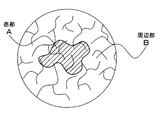
例えば、図2は、白色LED17を用いない従来の視野であるが、患部Aだけは蛍光を発して観察できるものの、その周辺部Bは暗くて観察することができない。これに対し、図3は、本実施例の白色LED17を用いた視野で、患部Aだけでなく、その周辺部Bも明るい状態で観察することができる。従って、術者にとって手術を安全に且つ容易に行えるようになる。
For example, FIG. 2 shows a conventional visual field that does not use the
白色LED17が患部Aの蛍光観察を邪魔しないで、その周辺部Bを確実に照らせるのは、白色LED17の発光特性による。すなわち、白色LED17は、図4に示すように、患部Aの蛍光に相当する波長(672nm)が他の波長領域よりも相対的に低い発光強度を有する可視光を発する特性を有している。従って、患部Aの蛍光観察の邪魔とならず、白色LED17をそのまま蛍光観察時の明視野光源として用いることができる。
The
また、この実施例の手術顕微鏡1は、取入口15に対して着脱自在なアタッチメント16に白色LED17と半導体レーザー照射装置18を搭載したため、それらを他の手段により患部Aに向けて支持する必要がなく、便利である。
In addition, since the surgical microscope 1 of this embodiment includes the
更に、不使用時にはアタッチメント16を外しておくことができ便利であると共に、白色LED17や半導体レーザー照射装置18のメンテナンス(交換調整等)も容易である。アタッチメント16を外した場合は、通常光源11を利用して、通常観察を行うことができる。
Furthermore, the
この実施例では、明視野光源として白色LED17を用いる例を示したが、他の可視光を発する光源を用いて、蛍光の波長の光だけをフィルターによりカットするようにしても良い。
In this embodiment, an example in which the
1 手術顕微鏡
10 ノッチフィルター
11 通常光源
15 取入口
16 アタッチメント
17 白色LED
17a 白色照明
18 半導体レーザー照射装置(励起光源)
18a レーザー(励起光)
19 バンドパスフィルター
A 患部
B 周辺部
1
18a Laser (excitation light)
19 Band pass filter A Affected area B Peripheral area
Claims (5)
前記患部及び周辺部を観察する際に前記励起光の反射光をカットすると共に前記蛍光を通過させるノッチフィルターと、
観察光の取入口の周囲に位置し、前記患部及び周辺部を照明する明視野光源とを備え、
前記明視野光源は、前記患部の蛍光に相当する波長領域が、他の領域よりも相対的に低い発光強度を有するか、またはフィルターによりカットされた可視光を発することを特徴とする手術顕微鏡 A semiconductor laser irradiation device that emits fluorescence by irradiating the affected area where photosensitizers are integrated with excitation light; and
A notch filter that cuts off the reflected light of the excitation light and passes the fluorescence when observing the affected part and the peripheral part;
A bright field light source located around the observation light intake and illuminating the affected area and the peripheral area;
The operation microscope characterized in that the bright field light source emits visible light in which a wavelength region corresponding to fluorescence of the affected part has a relatively lower emission intensity than other regions or is cut by a filter
Priority Applications (3)
| Application Number | Priority Date | Filing Date | Title |
|---|---|---|---|
| JP2005119082A JP4960602B2 (en) | 2005-04-15 | 2005-04-15 | Bright field light source for fluorescence observation and surgical microscope equipped with the same |
| US11/401,843 US20060232855A1 (en) | 2005-04-15 | 2006-04-12 | Bright-field light source for fluorescence observation and surgical microscope with bright-field light source |
| DE102006017799A DE102006017799A1 (en) | 2005-04-15 | 2006-04-18 | Bright field light source for observation of fluorescence and surgical microscope with bright field light source |
Applications Claiming Priority (1)
| Application Number | Priority Date | Filing Date | Title |
|---|---|---|---|
| JP2005119082A JP4960602B2 (en) | 2005-04-15 | 2005-04-15 | Bright field light source for fluorescence observation and surgical microscope equipped with the same |
Related Child Applications (1)
| Application Number | Title | Priority Date | Filing Date |
|---|---|---|---|
| JP2008082038A Division JP4960915B2 (en) | 2008-03-26 | 2008-03-26 | Attachment for surgical microscope |
Publications (3)
| Publication Number | Publication Date |
|---|---|
| JP2006296516A JP2006296516A (en) | 2006-11-02 |
| JP2006296516A5 JP2006296516A5 (en) | 2008-05-08 |
| JP4960602B2 true JP4960602B2 (en) | 2012-06-27 |
Family
ID=37055675
Family Applications (1)
| Application Number | Title | Priority Date | Filing Date |
|---|---|---|---|
| JP2005119082A Expired - Fee Related JP4960602B2 (en) | 2005-04-15 | 2005-04-15 | Bright field light source for fluorescence observation and surgical microscope equipped with the same |
Country Status (3)
| Country | Link |
|---|---|
| US (1) | US20060232855A1 (en) |
| JP (1) | JP4960602B2 (en) |
| DE (1) | DE102006017799A1 (en) |
Families Citing this family (9)
| Publication number | Priority date | Publication date | Assignee | Title |
|---|---|---|---|---|
| JP4800248B2 (en) * | 2007-03-23 | 2011-10-26 | 三鷹光器株式会社 | Surgical microscope system |
| DE102007041003A1 (en) * | 2007-05-31 | 2008-12-04 | Carl Zeiss Surgical Gmbh | Surgical microscope with illumination device |
| DE102008045671A1 (en) * | 2008-09-03 | 2010-03-04 | Bundesrepublik Deutschland, vertreten durch den Präsidenten der Bundesanstalt für Geowissenschaften und Rohstoffe | Fluorescent microscope, especially for rock studies, has an integrated LED light source for use in the field |
| DE102009025127A1 (en) * | 2009-06-17 | 2010-12-23 | Carl Zeiss Surgical Gmbh | Lighting device for an optical observation device |
| WO2016103643A1 (en) | 2014-12-25 | 2016-06-30 | Sony Corporation | Medical imaging system, illumination device, and method |
| CN104570311A (en) * | 2014-12-26 | 2015-04-29 | 中国科学院苏州生物医学工程技术研究所 | Fluorescence microscope based on multi-spectral LED light source |
| DE102015119590B4 (en) | 2015-11-12 | 2023-02-09 | Carsten Jung | Illumination arrangement and microscope |
| JP6619996B2 (en) * | 2015-11-24 | 2019-12-11 | 三鷹光器株式会社 | Surgical stereoscopic observation device |
| WO2020133110A1 (en) * | 2018-12-27 | 2020-07-02 | 深圳市奥沃医学新技术发展有限公司 | Light field lamp assembly, light field indicator and radiotherapy device |
Family Cites Families (16)
| Publication number | Priority date | Publication date | Assignee | Title |
|---|---|---|---|---|
| JP3015082B2 (en) * | 1990-08-28 | 2000-02-28 | オリンパス光学工業株式会社 | Microscope capable of simultaneous observation of transmission and epi-illumination and automatic light control method thereof |
| US5325231A (en) * | 1991-03-22 | 1994-06-28 | Olympus Optical Co., Ltd. | Microscope illuminating apparatus |
| DE4320579C2 (en) * | 1992-06-15 | 2000-06-15 | Topcon Corp | Surgical microscope |
| JP3539436B2 (en) * | 1993-12-27 | 2004-07-07 | オリンパス株式会社 | Scanning laser microscope |
| JP3872856B2 (en) * | 1997-01-23 | 2007-01-24 | オリンパス株式会社 | Fluorescence microscope |
| WO2000002882A1 (en) * | 1998-07-10 | 2000-01-20 | Meiji Seika Kaisha Ltd. | Novel x-ray intercepting metal complexes of chlorin derivatives |
| JP2000089124A (en) * | 1998-09-14 | 2000-03-31 | Nikon Corp | Compound microscope |
| DE19845603C2 (en) * | 1998-10-05 | 2000-08-17 | Leica Microsystems | Illumination device for a microscope |
| DE10108254A1 (en) * | 2001-02-21 | 2002-08-22 | Leica Microsystems | Optical viewing device with device for partially reducing the intensity of the lighting |
| WO2003019072A1 (en) * | 2001-08-23 | 2003-03-06 | Yukiyasu Okumura | Color temperature-regulable led light |
| JP2003315678A (en) * | 2002-04-22 | 2003-11-06 | Mitsutoyo Corp | Ring illuminator |
| DE10339784B4 (en) * | 2002-08-28 | 2021-09-16 | Carl Zeiss Meditec Ag | Microscopy system and microscopy method |
| DE10242983B4 (en) * | 2002-09-17 | 2016-01-28 | Leica Microsystems Gmbh | Ophthalmic surgical microscope with object illumination |
| JP4354207B2 (en) * | 2003-04-15 | 2009-10-28 | オリンパス株式会社 | Microscope equipment |
| DE10339619A1 (en) * | 2003-08-28 | 2005-03-24 | Leica Microsystems (Schweiz) Ag | Stereomicroscope with integrated epi-illumination device |
| EP1727460A2 (en) * | 2004-03-11 | 2006-12-06 | The General Hospital Corporation | Method and system for tomographic imaging using fluorescent proteins |
-
2005
- 2005-04-15 JP JP2005119082A patent/JP4960602B2/en not_active Expired - Fee Related
-
2006
- 2006-04-12 US US11/401,843 patent/US20060232855A1/en not_active Abandoned
- 2006-04-18 DE DE102006017799A patent/DE102006017799A1/en not_active Withdrawn
Also Published As
| Publication number | Publication date |
|---|---|
| JP2006296516A (en) | 2006-11-02 |
| DE102006017799A1 (en) | 2006-10-19 |
| US20060232855A1 (en) | 2006-10-19 |
Similar Documents
| Publication | Publication Date | Title |
|---|---|---|
| JP4960602B2 (en) | Bright field light source for fluorescence observation and surgical microscope equipped with the same | |
| JP5945104B2 (en) | Fluorescent surgical stereo microscope | |
| JP5227811B2 (en) | Ophthalmic equipment | |
| US20130236059A1 (en) | Fluorescence reflection imaging device with two wavelengths | |
| JP4996183B2 (en) | Microscope and lamp house | |
| US7933066B2 (en) | Surgical microscope having an illuminating arrangement | |
| JP2001190499A (en) | Ophthalmic device | |
| JP2008268852A5 (en) | ||
| JP2007311114A (en) | Lighting optical system using solid light emitting element emitting white light, and optical device equipped with it | |
| JPWO2011007435A1 (en) | Aperture stop | |
| JP2005323737A (en) | Endoscope device | |
| JP2011177273A (en) | Slit-lamp microscope | |
| US20100261966A1 (en) | Optical observation unit and method for ensuring an unchanging illumination intensity when changing the color temperature of the illumination | |
| JP5268583B2 (en) | Ophthalmic imaging equipment | |
| JP2009072213A (en) | Endoscope light source unit and endoscope system | |
| JP4960915B2 (en) | Attachment for surgical microscope | |
| US20050267450A1 (en) | Ophthalmic treatment apparatus | |
| JP2009140827A (en) | External light source apparatus | |
| US8488239B2 (en) | Medical stand device, medical microscope, and external illuminating device | |
| JP4869606B2 (en) | Laser light irradiation device and microscope device with laser light irradiation device | |
| JP3050582B2 (en) | Surgical microscope | |
| JP2009136578A (en) | Medical microscope | |
| JP2010017318A (en) | Laser surgery apparatus | |
| JP2009136581A (en) | Medical device | |
| KR102368406B1 (en) | light source device |
Legal Events
| Date | Code | Title | Description |
|---|---|---|---|
| RD02 | Notification of acceptance of power of attorney |
Free format text: JAPANESE INTERMEDIATE CODE: A7422 Effective date: 20060525 |
|
| A521 | Request for written amendment filed |
Free format text: JAPANESE INTERMEDIATE CODE: A523 Effective date: 20080326 |
|
| A621 | Written request for application examination |
Free format text: JAPANESE INTERMEDIATE CODE: A621 Effective date: 20080326 |
|
| A131 | Notification of reasons for refusal |
Free format text: JAPANESE INTERMEDIATE CODE: A131 Effective date: 20110201 |
|
| A521 | Request for written amendment filed |
Free format text: JAPANESE INTERMEDIATE CODE: A523 Effective date: 20110404 |
|
| A131 | Notification of reasons for refusal |
Free format text: JAPANESE INTERMEDIATE CODE: A131 Effective date: 20111213 |
|
| A521 | Request for written amendment filed |
Free format text: JAPANESE INTERMEDIATE CODE: A523 Effective date: 20120206 |
|
| TRDD | Decision of grant or rejection written | ||
| A01 | Written decision to grant a patent or to grant a registration (utility model) |
Free format text: JAPANESE INTERMEDIATE CODE: A01 Effective date: 20120228 |
|
| A01 | Written decision to grant a patent or to grant a registration (utility model) |
Free format text: JAPANESE INTERMEDIATE CODE: A01 |
|
| A61 | First payment of annual fees (during grant procedure) |
Free format text: JAPANESE INTERMEDIATE CODE: A61 Effective date: 20120323 |
|
| FPAY | Renewal fee payment (event date is renewal date of database) |
Free format text: PAYMENT UNTIL: 20150330 Year of fee payment: 3 |
|
| R150 | Certificate of patent or registration of utility model |
Ref document number: 4960602 Country of ref document: JP Free format text: JAPANESE INTERMEDIATE CODE: R150 Free format text: JAPANESE INTERMEDIATE CODE: R150 |
|
| R250 | Receipt of annual fees |
Free format text: JAPANESE INTERMEDIATE CODE: R250 |
|
| R250 | Receipt of annual fees |
Free format text: JAPANESE INTERMEDIATE CODE: R250 |
|
| R250 | Receipt of annual fees |
Free format text: JAPANESE INTERMEDIATE CODE: R250 |
|
| R250 | Receipt of annual fees |
Free format text: JAPANESE INTERMEDIATE CODE: R250 |
|
| R250 | Receipt of annual fees |
Free format text: JAPANESE INTERMEDIATE CODE: R250 |
|
| R250 | Receipt of annual fees |
Free format text: JAPANESE INTERMEDIATE CODE: R250 |
|
| R250 | Receipt of annual fees |
Free format text: JAPANESE INTERMEDIATE CODE: R250 |
|
| LAPS | Cancellation because of no payment of annual fees |