JP4960468B2 - Magnetic resonance imaging system - Google Patents
Magnetic resonance imaging system Download PDFInfo
- Publication number
- JP4960468B2 JP4960468B2 JP2010073704A JP2010073704A JP4960468B2 JP 4960468 B2 JP4960468 B2 JP 4960468B2 JP 2010073704 A JP2010073704 A JP 2010073704A JP 2010073704 A JP2010073704 A JP 2010073704A JP 4960468 B2 JP4960468 B2 JP 4960468B2
- Authority
- JP
- Japan
- Prior art keywords
- correction
- correction parameter
- map
- parameter
- prediction
- Prior art date
- Legal status (The legal status is an assumption and is not a legal conclusion. Google has not performed a legal analysis and makes no representation as to the accuracy of the status listed.)
- Active
Links
Images


Classifications
-
- G—PHYSICS
- G01—MEASURING; TESTING
- G01R—MEASURING ELECTRIC VARIABLES; MEASURING MAGNETIC VARIABLES
- G01R33/00—Arrangements or instruments for measuring magnetic variables
- G01R33/20—Arrangements or instruments for measuring magnetic variables involving magnetic resonance
- G01R33/44—Arrangements or instruments for measuring magnetic variables involving magnetic resonance using nuclear magnetic resonance [NMR]
- G01R33/48—NMR imaging systems
- G01R33/54—Signal processing systems, e.g. using pulse sequences ; Generation or control of pulse sequences; Operator console
- G01R33/56—Image enhancement or correction, e.g. subtraction or averaging techniques, e.g. improvement of signal-to-noise ratio and resolution
- G01R33/565—Correction of image distortions, e.g. due to magnetic field inhomogeneities
- G01R33/56509—Correction of image distortions, e.g. due to magnetic field inhomogeneities due to motion, displacement or flow, e.g. gradient moment nulling
Description
この技術は、所定の基準位置の体動による移動量に基づいて、所望の撮像対象の体動を補正して撮像する磁気共鳴イメージング装置に関する。 This technique relates to a magnetic resonance imaging apparatus that performs imaging by correcting body movement of a desired imaging target based on a movement amount due to body movement at a predetermined reference position.
磁気共鳴イメージング装置はX線CT装置や超音波装置よりも長い時間を撮像に要するため、体動により動く対象物を撮像する場合にアーチファクトが生じやすい。 Since the magnetic resonance imaging apparatus requires a longer time for imaging than the X-ray CT apparatus or the ultrasonic apparatus, artifacts are likely to occur when imaging an object that moves due to body movement.
例えば、呼吸により動く心臓を撮像対象とする場合、呼吸による心臓の動きは、横隔膜の動きに比例することが知られている。そこで、横隔膜を基準位置として、ナビゲータパルスを用いて呼吸による横隔膜の動きをモニタし、この横隔膜の位置に基づいてMR信号を取得する位置を、平行移動などの変換により補正することで、呼吸による心臓の動きを補正する方法がある。または、取得したMR信号とその時の横隔膜の位置情報を組として保存しておき、取得したMR信号を横隔膜の位置情報を基に補正した後で、画像データを再構成する方法がある。これらの方法により、動きアーチファクトの少ないMR画像(「第2画像データ」)を撮像することができる。 For example, when a heart that moves due to respiration is used as an imaging target, it is known that the movement of the heart due to respiration is proportional to the movement of the diaphragm. Therefore, with the diaphragm as a reference position, the movement of the diaphragm due to respiration is monitored using a navigator pulse, and the position where the MR signal is acquired based on the position of the diaphragm is corrected by conversion such as translation, so that There are ways to compensate for heart movement. Alternatively, there is a method in which the acquired MR signal and the position information of the diaphragm at that time are stored as a set, and after the acquired MR signal is corrected based on the position information of the diaphragm, the image data is reconstructed. With these methods, an MR image (“second image data”) with little motion artifact can be captured.
横隔膜の動きと心臓の動きの関係は被検体ごとに異なる。補正のための変換パラメータ(「体動補正パラメータ」)を被検体ごとに算出することにより、動き補正の正確さが改善される。 The relationship between diaphragm movement and heart movement varies from subject to subject. By calculating a conversion parameter for correction (“body motion correction parameter”) for each subject, the accuracy of motion correction is improved.
従来の磁気共鳴イメージング装置は、基準位置と撮像対象の体動をモニタするためのMR画像(「第1画像データ」)を撮像する。従来の磁気共鳴イメージング装置は、この第1画像データから被検体ごとに体動補正パラメータを自動で算出する。従来の磁気共鳴イメージング装置は、算出された体動補正パラメータを用いて第2画像データを撮像する。 A conventional magnetic resonance imaging apparatus captures an MR image (“first image data”) for monitoring a reference position and body motion of an imaging target. A conventional magnetic resonance imaging apparatus automatically calculates body movement correction parameters for each subject from the first image data. The conventional magnetic resonance imaging apparatus captures the second image data using the calculated body motion correction parameter.
しかし、厳密には、心臓などの撮像対象は体動により複雑な動きをし、また、基準位置が同じであっても撮像対象が同じ形、位置でない場合がある。このため、被検体ごとの体動補正パラメータを算出し、平行移動や平行移動よりも高次の変換により撮像対象の体動補正を行っても、補正の誤差は発生し、また、その誤差の量も撮像対象の各位置で異なる。 However, strictly speaking, an imaging target such as a heart moves complicatedly due to body movement, and the imaging target may not have the same shape and position even if the reference position is the same. Therefore, even if the body motion correction parameter for each subject is calculated and the body motion correction of the imaging target is performed by higher-order conversion than parallel movement or parallel movement, a correction error occurs, and the error The amount also differs at each position of the imaging target.
従来の磁気共鳴イメージング装置では、設定した体動補正パラメータによって、撮像対象の各位置でどの程度体動補正が行えるかを確認できなかった。 In the conventional magnetic resonance imaging apparatus, it has not been possible to confirm how much body motion correction can be performed at each position of the imaging target by the set body motion correction parameter.
そこで、本発明は、撮像対象の各位置でどの程度体動補正できるかを、使用者が容易に確認できる磁気共鳴イメージング装置を提供することを目的とする。 Therefore, an object of the present invention is to provide a magnetic resonance imaging apparatus in which a user can easily confirm how much body motion can be corrected at each position of an imaging target.
磁気共鳴イメージング装置は、被検体の所定の基準位置と所望の対象部位を含む複数枚の第1画像データを撮像する第1撮像部と、前記第1画像データのうちの第1参照フレームと第2参照フレームの間での、前記基準位置と前記対象部位を含む複数の局所位置の移動量を算出する移動量算出部と、前記被検体の体動を補正するための第1補正パラメータを前記移動量から求める体動補正パラメータ設定部と、前記局所位置のそれぞれについて、前記移動量に基づく予測位置と前記第1補正パラメータに基づく予測補正位置との予測補正誤差を求めるとともに、前記予測補正誤差を画素値として有する予測誤差マップを生成する誤差マップ生成部と、前記予測誤差マップと前記第1画像データを表示する表示部とを有する。 The magnetic resonance imaging apparatus includes: a first imaging unit that captures a plurality of first image data including a predetermined reference position of a subject and a desired target region; a first reference frame of the first image data; A movement amount calculation unit that calculates movement amounts of a plurality of local positions including the reference position and the target region between two reference frames; and a first correction parameter for correcting body movement of the subject. For each of the body movement correction parameter setting unit determined from the movement amount and the local position, a prediction correction error between the prediction position based on the movement amount and the prediction correction position based on the first correction parameter is obtained, and the prediction correction error An error map generation unit that generates a prediction error map having the pixel value as a pixel value, and a display unit that displays the prediction error map and the first image data.
本発明によれば、設定した体動補正パラメータにより、撮像対象の各位置でどの程度体動補正できるかを容易に予測することができる。 According to the present invention, it is possible to easily predict how much body motion can be corrected at each position of the imaging target by the set body motion correction parameter.
以下、図面を参照して実施例を説明する。 Embodiments will be described below with reference to the drawings.
図1から図5を参照して、第1の実施例の磁気共鳴イメージング装置1を説明する。図1は人間の胸部に関する磁気共鳴画像の模式図である。図1は本実施例の撮像対象t及び基準位置sを示す。撮像対象tは心臓である。基準位置tは右肺L1の下の横隔膜D上の1点である。本実施例の磁気共鳴イメージング装置1は、呼吸による心臓の動きを補正し、補正された画像データ(第2画像データ)を撮像する。以下の説明では、心臓は横隔膜Dの体軸方向の動きに比例して体軸方向と平行に動くものと仮定する。そして、撮像位置を体軸方向に平行移動させることで心臓の動きを補正する場合について説明する。例えば、体軸方向の横隔膜Dの移動量dsと体軸方向の撮像位置の補正量dcとの関係は式(1)で表される。
![]()
![]()
式(1)の係数aは横隔膜Dと心臓の動きの関係を表す体動補正パラメータである。横隔膜の動きと心臓の動きの関係は被検体ごとに異なるため、体動補正パラメータを被検体ごとに算出することで、より正確な動き補正が可能になる。 The coefficient a in the equation (1) is a body motion correction parameter that represents the relationship between the diaphragm D and the heart motion. Since the relationship between the movement of the diaphragm and the movement of the heart differs for each subject, more accurate motion correction can be performed by calculating the body motion correction parameter for each subject.
そこで、被検体ごとに異なる体動補正パラメータを算出するために、第2画像データを撮像する前に、横隔膜と心臓を含む複数枚の画像データ(第1画像データ)を撮像する。 Therefore, in order to calculate different body motion correction parameters for each subject, a plurality of pieces of image data (first image data) including the diaphragm and the heart are imaged before the second image data is imaged.
本実施例の磁気共鳴イメージング装置1は、第1画像データから体動補正パラメータ(第1補正パラメータ)を求め、体動補正パラメータを用いた補正によって、撮像対象である心臓の各位置で、どの程度の誤差で補正可能であるかを予測する。そして、本実施例の磁気共鳴イメージング装置1は、予測された誤差を可視化し、可視化された誤差をユーザに提示する。
The magnetic
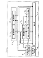
図2は本実施例の磁気共鳴イメージング装置1のブロック図である。磁気共鳴イメージング装置1は、撮像部2、処理部3、表示部4、体動補正パラメータ設定部5、及び、修正情報入力部6を有する。
FIG. 2 is a block diagram of the magnetic
撮像部2は第1撮像部2aと第2撮像部2bを有する。第1撮像部2aは、被検体の基準位置と撮像対象を含む、複数枚の画像データである第1画像データを取得する。第2撮像部2bは、ナビゲータパルスを用いて基準位置の動きをモニタするとともに、その基準位置の動きに基づいて撮像対象の動きを補正した画像データである第2画像データを取得する。第1撮像部2aにより得られる第1画像データは、移動量算出部3a、表示部4に入力される。また、第2撮影部2bにより得られる第2画像データは、表示部4に入力される。
The
処理部3は、移動量算出部3a、誤差マップ生成部3bを有する。
The
移動量算出部3aは、第1画像データの内の第1参照フレームの基準位置と対象部位を含む複数の局所位置(以下、「対象位置」と呼ぶ)から第2参照フレームへの移動量を算出する。算出された移動量は、誤差マップ生成部3b、体動補正パラメータ設定部5に入力される。
The movement
誤差マップ生成部3bは、基準位置の移動量と体動補正パラメータに基づいて、対象位置ごとの予測補正位置を算出する。誤差マップ生成部3bは、対象位置ごとの移動量から対象位置の位置を求める。誤差マップ生成部3bは、予測補正位置と求められた位置との誤差である予測補正誤差を算出する。誤差マップ生成部3bは、予測補正誤差を画素値として有する予測誤差マップを生成する。生成された予測誤差マップは、表示部4に入力される。体動補正パラメータが修正された場合、誤差マップ生成部3bは予測誤差マップを更新する。更新された予測誤差マップは、表示部4に入力される。
The error
表示部4は、液晶表示装置やCRTなどのディスプレイである。
The
体動補正パラメータ設定部5は、第2画像データの撮像や予測補正誤差の算出に必要な体動補正パラメータを設定する。例えば、体動補正パラメータ設定部5は、体動補正パラメータとして、被検体によらず固定の値を設定しても構わないし、後述するように、移動量算出部3aが算出した移動量に基づいて、体動補正パラメータ設定部5が被検体ごとに算出しても構わない。設定された体動補正パラメータは、誤差マップ生成部3b、第2撮像部2bに入力される。
The body motion correction parameter setting unit 5 sets body motion correction parameters necessary for capturing the second image data and calculating the prediction correction error. For example, the body movement correction parameter setting unit 5 may set a fixed value as the body movement correction parameter regardless of the subject, and based on the movement amount calculated by the movement
修正情報入力部6は、体動補正パラメータの修正情報を入力する手段である。例えば、修正情報入力部6は、マウスやキーボード、トラックボール、タッチパッドなどのユーザインターフェースにより実現される。修正された体動補正パラメータは、体動補正パラメータ設定部5へ入力される。
The correction
図3は、本実施例の磁気共鳴イメージング装置1の動作を示すフローチャートである。
FIG. 3 is a flowchart showing the operation of the magnetic
ステップS1では、第1撮像部2aが、被検体の基準位置と撮像対象を含む複数枚の画像データである第1画像データを撮像し、移動量算出部3aへ出力する。
In step S1, the
ステップS2では、移動量算出3aは、第1画像データの内の第1参照フレームの基準位置と対象位置の第2参照フレームへの移動量を算出する。
In step S2, the
本実施例では、第1参照フレームは第1画像データのうちの任意の1枚の画像データであり、第2参照フレームは残りの第1画像データである。N枚の第1画像データが存在する場合、N−1枚の第2参照フレームが存在する。つまり、基準位置と対象位置ごとにN−1個の移動量が算出される。ただし、第1参照フレームと第2参照フレームの選択はこれに限らず、第1画像データから考えられる全ての第1参照フレームと第2参照フレームの組み合わせであっても構わない。基準位置と対象位置ごとに、1つ以上の移動量が算出できれば構わない。 In this embodiment, the first reference frame is any one piece of image data among the first image data, and the second reference frame is the remaining first image data. When N pieces of first image data exist, there are N−1 second reference frames. That is, N−1 movement amounts are calculated for each reference position and target position. However, the selection of the first reference frame and the second reference frame is not limited to this, and may be a combination of all the first reference frames and the second reference frames that can be considered from the first image data. It is only necessary that one or more movement amounts can be calculated for each reference position and target position.
また、「移動量の算出」は、第1参照フレームの基準位置と対象位置のそれぞれを中心位置としたテンプレートを用意し、第2参照フレームへのマッチングを行うことで求めても構わないし、第1参照フレームと第2参照フレームの輝度パターンが一致するように第1参照フレームまたは第2参照フレームを変形、位置合わせを行うことで基準位置と対象位置ごとの移動量を算出しても構わない。 Further, the “calculation of the movement amount” may be obtained by preparing a template with the reference position and the target position of the first reference frame as the center positions and performing matching with the second reference frame. The movement amount for each reference position and target position may be calculated by deforming and aligning the first reference frame or the second reference frame so that the luminance patterns of the 1 reference frame and the second reference frame match. .
また、「対象位置」は、第1参照フレーム上の全ての点でも構わないし、等間隔にサンプリングした点でも構わない。第1参照フレーム上の撮像対象の境界の点集合を対象位置として用いても構わない。 The “target position” may be all points on the first reference frame, or may be points sampled at equal intervals. A point set on the boundary of the imaging target on the first reference frame may be used as the target position.
ステップS3では、体動補正パラメータ設定部5は体動補正パラメータを設定する。本実施例では、「体動補正パラメータ」は基準位置の移動量と撮像位置の補正量の関係を表す比例定数であり、式(1)のパラメータaである。 In step S3, the body motion correction parameter setting unit 5 sets a body motion correction parameter. In the present embodiment, the “body motion correction parameter” is a proportional constant representing the relationship between the movement amount of the reference position and the correction amount of the imaging position, and is the parameter “a” in Expression (1).
本実施例の体動補正パラメータ設定部5は、任意の対象位置xtにおける予測補正誤差(ステップS4で説明)を最小にする体動補正パラメータを被検体ごとに算出する。予測補正誤差については後述する。体動補正パラメータの算出方法は、実施例2のステップS14にて詳細に説明される。体動補正パラメータの設定は、この方法に限定されず、例えば、1.0や0.0などの被検体によらず固定の値としても構わない。 Motion correction parameter setting unit 5 of the present embodiment calculates the motion correction parameters to minimize the prediction correction error (described in step S4) at an arbitrary object position x t for each subject. The prediction correction error will be described later. The method for calculating the body motion correction parameter will be described in detail in step S14 of the second embodiment. The setting of the body motion correction parameter is not limited to this method, and may be a fixed value regardless of the subject such as 1.0 or 0.0, for example.
ステップS4では、誤差マップ生成部3bは、基準位置の移動量と体動補正パラメータに基づいて、対象位置ごとの予測補正位置を求める。誤差マップ生成部3bは、移動量算出部3aにより算出された対象位置ごとの移動量から、対象位置ごとの位置を求める。誤差マップ生成部3bは、求められた位置と予測補正位置との誤差である予測補正誤差を算出する。誤差マップ生成部3bは予測誤差マップを生成する。予測誤差マップは予測補正誤差を画素値として有する画像である。対象位置xtごとの予測補正誤差MAPerr(xt)は、例えば、式(2)で求められる。

移動量mvj(xt)は対象位置xtの移動量である。移動量mvj(xt)は、第1参照フレームとN-1枚あるうちのj枚目の第2参照フレームから算出される。移動量mvj(xs)は基準位置xsの移動量である。予測補正量d'c、jは、対象位置xtの移動量mvj(xt)と体動補正パラメータaから算出される。上述したように、本実施例では撮像対象の補正は体軸方向のみである。対象位置の移動量、基準位置の移動量、予測補正量は全て体軸方向のスカラー値を示す。予測補正誤差は式(2)で示すような二乗誤差の総和に限定されず、例えば、絶対値誤差の総和など、対象位置ごとの予測補正位置と移動量の差を表す指標であれば良い。 The movement amount mv j (x t ) is the movement amount of the target position x t . The movement amount mv j (x t ) is calculated from the first reference frame and the j second reference frame among the N−1 frames. The movement amount mv j (x s ) is the movement amount of the reference position x s . The predicted correction amount d ′ c, j is calculated from the movement amount mv j (x t ) of the target position x t and the body motion correction parameter a. As described above, in this embodiment, the imaging target is corrected only in the body axis direction. The movement amount of the target position, the movement amount of the reference position, and the prediction correction amount all indicate scalar values in the body axis direction. The prediction correction error is not limited to the total sum of square errors as shown in Expression (2), and may be an index representing the difference between the prediction correction position and the movement amount for each target position, such as the sum of absolute value errors.
予測誤差マップは、式(2)で算出した予測補正誤差を画素値として有する画像である。対象位置の予測補正誤差は計算可能である。算出した予測補正誤差の値と位置に基づいて補間して算出された予測補正誤差を予測誤差マップの画素として加えても構わない。 The prediction error map is an image having the prediction correction error calculated by Expression (2) as a pixel value. The prediction correction error of the target position can be calculated. A prediction correction error calculated by interpolation based on the calculated prediction correction error value and position may be added as a pixel of the prediction error map.
ステップS5では、誤差マップ生成部3bで生成された予測誤差マップを、表示部4が表示する。
In step S5, the
図4は予測誤差マップと第1画像データの表示画面の例である。画像10aは予測誤差マップと第1画像データとの合成画像である。画像10aの各画素値には予測補正誤差の値に応じた値が設定される。例えば、白い領域(明るい領域)ほど予測補正誤差が小さくなるように設定される。今設定されている体動補正パラメータでは、撮像対象の図中右上と左下の位置(図4の黒矢印10c及び10d)での補正誤差は、撮像対象の図中右(図4の白矢印10e)の位置での補正誤差よりも小さい。図4の画像10bは、予測補正誤差と表示輝度の関係を表す。このように、第1画像データと予測誤差マップを合成して表示したり、予測誤差マップの値と表示輝度との関係を示す画像を並べて表示することで、予測補正誤差の分布状況を容易に確認することができる。
FIG. 4 is an example of a display screen for the prediction error map and the first image data. The
ステップS6では、使用者が修正情報入力部6を操作して体動補正パラメータの修正を行ったか否かを判定する。使用者が修正を行った場合にはステップS7に進み(図3中の「yes」の場合)、使用者が修正をしなかった場合にはステップS8に進む(図3中の「no」の場合)。
In step S6, it is determined whether the user has operated the correction
使用者は、修正情報入力部5のユーザインタフェース(例えばマウス)を用いて図5に示すGUIを操作することにより、体動補正パラメータの修正を行う。GUIは、体動補正パラメータを調整するためのスライダ20aや、体動補正パラメータの数値を直接指定するためのエディットボックス20bを有する。
The user corrects the body motion correction parameter by operating the GUI shown in FIG. 5 using the user interface (for example, mouse) of the correction information input unit 5. The GUI has a
ステップS7では、修正情報入力部6は使用者の入力に基づいて体動補正パラメータを修正し、ステップS4に戻り、誤差マップ生成部3bが予測誤差マップを再び生成する。
In step S7, the correction
ステップS8では、基準位置の動きと体動補正パラメータとに基づいて第2撮像部2bが撮像対象の動きを補正する。第2撮像部2bは補正されたMR画像である第2画像データを取得する。基準位置の動きは、上述したように、ナビゲータパルスを用いて検出される。
In step S8, the
上述したように、本実施例の磁気共鳴イメージング装置1は、第1画像データ及び調整可能な体動補正パラメータを用いて予測誤差マップを生成する。そして、本実施例の磁気共鳴イメージング装置1は第1画像データと予測誤差マップとを表示する。使用者は予測誤差マップに基づいて、設定された体動補正パラメータによる、撮像対象の各位置での補正の程度を容易に予測することができる。このことにより、使用者の撮り直しの労力が減る。本実施例の磁気共鳴イメージング装置1は、使用者が効率良く撮像することを支援できる。
As described above, the magnetic
以下、第2の実施例である磁気共鳴イメージング装置10について説明する。図6は第2の実施例に係る磁気共鳴イメージング装置10のブロック図である。本実施例の磁気共鳴イメージング装置10は、図1の磁気共鳴イメージング装置1にパラメータマップ生成部3cを追加した構成に相当する。パラメータマップ生成部3cは、最小の予測補正誤差に対応する体動補正パラメータ(「第2補正パラメータ」)を求めるとともに、第2補正パラメータの値の空間的な分布を示す第2補正パラメータマップを生成する。
Hereinafter, the magnetic
この構成とすることで、使用者は、補正パラメータ値の撮像対象の各位置での分布を容易に確認することができる。 With this configuration, the user can easily check the distribution of the correction parameter value at each position of the imaging target.
なお、図6において、パラメータマップ生成部3c以外のブロックについては、第1の実施例と説明が重複するため、説明を省略する。
In FIG. 6, the description of the blocks other than the
パラメータマップ生成部3cは、基準位置と対象位置の移動量から求まる、第2補正パラメータを算出し、第2補正パラメータマップを生成する。生成された第2補正パラメータマップは、表示部4に入力される。
The
第2の実施例に係る磁気共鳴イメージング装置10の動作について、図7のフローチャートを用いて説明する。
The operation of the magnetic
図7のステップS11は第1の実施形態(図3)のステップS1に対応する。ステップS12はステップS2に対応する。ステップS13はステップS3に対応する。ステップS15はステップS4に対応する。ステップS18はステップS7に対応する。、ステップS19はステップS8に対応する。本実施例では、説明が重複するため、これらのステップの説明を省略する。 Step S11 in FIG. 7 corresponds to step S1 in the first embodiment (FIG. 3). Step S12 corresponds to step S2. Step S13 corresponds to step S3. Step S15 corresponds to step S4. Step S18 corresponds to step S7. Step S19 corresponds to step S8. In the present embodiment, since the description is duplicated, description of these steps is omitted.
ステップS14では、パラメータマップ生成部3cは、対象位置ごとに、予測補正誤差が最小となる第2補正パラメータを算出し、第2補正パラメータマップを生成する。
In step S14, the
以下に、本実施例での「第2補正パラメータ」の算出方法を説明する。 Hereinafter, a method of calculating the “second correction parameter” in the present embodiment will be described.
図8は、人間の胸部に関する磁気共鳴画像の模式図である。図8は本実施例での基準位置s、対象位置t1、t2の配置例を示す。本実施例では対象位置t1及びt2の第2補正パラメータを算出する。図9Aのグラフは、第1参照フレームからj番目の第2参照フレームへの基準位置sの移動量mv、j(xs)を示す。図9Bのグラフは、第1参照フレームからj番目の第2参照フレームへの対象位置t1の移動量mvj(xt1)を示す。図9Cのグラフは、第1参照フレームからj番目の第2参照フレームへの対象位置t2の移動量mvj(xt2)を示す。基準位置sは座標位置xsにある。対象位置t1は座標位置xt1にある。対象位置t2は座標位置xt2にある。また、図9A、B及びCの横軸は第2参照フレームの番号jである。図10は基準位置の動きと対象位置の動きの関係を表すグラフである。図10の横軸は移動量mv、j(xs)である。図10の縦軸は移動量mvj(xt1)及びmvj(xt2)である。 FIG. 8 is a schematic diagram of a magnetic resonance image relating to the human chest. FIG. 8 shows an arrangement example of the reference position s and the target positions t1 and t2 in the present embodiment. In this embodiment, the second correction parameters for the target positions t1 and t2 are calculated. The graph of FIG. 9A shows the amount of movement mv , j (x s ) of the reference position s from the first reference frame to the j-th second reference frame. The graph of FIG. 9B shows the amount of movement mv j (x t1 ) of the target position t1 from the first reference frame to the j-th second reference frame. The graph of FIG. 9C shows the amount of movement mv j (x t2 ) of the target position t2 from the first reference frame to the j-th second reference frame. The reference position s is at the coordinate position x s . The target position t1 is at the coordinate position xt1 . The target position t2 is at the coordinate position xt2 . 9A, 9B, and 9C, the horizontal axis is the number j of the second reference frame. FIG. 10 is a graph showing the relationship between the movement of the reference position and the movement of the target position. The horizontal axis in FIG. 10 is the movement amount mv , j (x s ). The vertical axis in FIG. 10 represents the movement amounts mv j (x t1 ) and mv j (x t2 ).
上述のように、第2補正パラメータは、対象位置ごとに、予測補正誤差が最小になるように求められる。対象位置t1の第2補正パラメータMapparam(xt1)は、式(3)を解くことで求められる。また、対象位置t2の第2補正パラメータMapparam(xt2)は、式(4)を解くことで求められる。
本実施例では、予測補正誤差は二乗誤差の総和である。したがって、第2補正パラメータMapparam(xt1)は図10でプロットされた点の回帰直線lt1の傾きで表され、第2補正パラメータMapparam(xt2)は、図10でプロットされた点の回帰直線lt2の傾きで表される。 In this embodiment, the prediction correction error is the sum of the square errors. Therefore, the second correction parameter Map param (x t1 ) is represented by the slope of the regression line l t1 of the points plotted in FIG. 10, and the second correction parameter Map param (x t2 ) is the point plotted in FIG. Is represented by the slope of the regression line l t2 .
式(3)、式(4)は最小二乗法により、式(5)、式(6)のように計算される。
このように、対象位置全てについて第2補正パラメータが算出され、、算出された値を画素値とする第2補正パラメータマップが生成される。また、上述の予測誤差マップと同様に、算出された位置とその第2補正パラメータに基づいた補間値を予測誤差マップの画素として加えても構わない。 In this way, the second correction parameter is calculated for all the target positions, and a second correction parameter map having the calculated value as the pixel value is generated. Similarly to the above-described prediction error map, an interpolation value based on the calculated position and the second correction parameter may be added as a pixel of the prediction error map.
ステップS16では、誤差マップ生成部3bにより生成された予測誤差マップと、パラメータマップ生成部3cにより生成された第2補正パラメータマップが、表示部4により表示される。
In step S16, the prediction error map generated by the
図11の画像30aは、第2補正パラメータマップと第1画像データの合成画像である。画像30aの各画素値には第2補正パラメータの値に応じた値が設定される。例えば、第2補正パラメータが大きい領域ほど白く(明るく)表示されるとともに、第2補正パラメータの値が小さい領域ほど黒く(暗く)表示されるように、画素値が設定される。図11の画像30aの例では、撮像対象の図中下(黒矢印30c)の位置の第2補正パラメータは、撮像対象の図中左上(白矢印30d)の位置の第2補正パラメータよりも大きい。また、図11の画像30bは第2補正パラメータMapparamと表示輝度の関係を表す。このように、第2補正パラメータマップは、第1画像データと合成して表示したり、また、第2補正パラメータの値と表示輝度との関係を示すバー(画像30b)を並べて表示することで、各位置での第2補正パラメータはどのような分布となっているかを容易に確認できる。
An
ステップS17では、使用者が入力部5を操作して体動補正パラメータの修正を行った場合には、ステップS15に進み(図7中の「yes」の場合)、使用者が修正をしなかった場合はステップS18へ進む(図7中の「no」の場合)。 In step S17, when the user operates the input unit 5 to correct the body motion correction parameter, the process proceeds to step S15 (in the case of “yes” in FIG. 7), and the user does not correct it. If YES in step S18, the flow advances to step S18 (in the case of “no” in FIG. 7).
体動補正パラメータの修正は、第1の実施例で説明した方法に限られない。例えば、ユーザインターフェースである入力部5のマウスを介して、使用者が第2補正パラメータマップ上の位置を指定し、指定された位置での第2補正パラメータ値が修正後の体動補正パラメータとして設定されても構わない。画像30a上で位置が指定されても構わないし、画像30b(第2補正パラメータ値を示すバー)上で位置が指定されても構わない。第2補正パラメータマップまたは画像30a上で位置が指定される場合、複数の位置が指定されても構わない。第2補正パラメータマップまたは画像30a上で指定された、矩形状の領域または任意形状の領域の中に含まれる複数の位置を用いても構わない。指定された複数の位置に基づいて第2補正パラメータを算出し、体動補正パラメータを修正しても構わない。
The correction of the body movement correction parameter is not limited to the method described in the first embodiment. For example, the user specifies a position on the second correction parameter map via the mouse of the input unit 5 that is a user interface, and the second correction parameter value at the specified position is used as the corrected body motion correction parameter. It does not matter if it is set. The position may be specified on the
例えば、式(7)で示すように、指定された複数点xt1、xt2、…、xtMの第2補正パラメータの平均から体動補正パラメータMapadjを修正する。
また、式(8)で示すように、指定された複数点で算出された移動量全てを用いて予測補正誤差が最小となる体動補正パラメータMapadjを再計算し、修正しても良い。
上述したように、本実施例の磁気共鳴イメージング装置10は、対象位置ごとに第2補正パラメータを算出し、第2補正パラメータマップを生成し、そして、第2補正パラメータマップを表示する。これにより、使用者は撮像対象の各位置での第2補正パラメータ値を容易に確認することができる。
As described above, the magnetic
上記第1の実施例、第2の実施例は、上記実施例に限定されず、その主旨を逸脱しない範囲で種々変形して実施できる。 The first and second embodiments are not limited to the above-described embodiments, and various modifications can be made without departing from the scope of the invention.
上記実施例では、撮像対象を心臓としたが、例えば、肝臓や腎臓などの腹部臓器でも良い。また、複数の部位を同時に撮像対象としても良い。 In the above embodiment, the imaging target is the heart, but it may be an abdominal organ such as a liver or a kidney. Moreover, it is good also considering several site | parts as imaging object simultaneously.
また、上記実施例では説明を簡単にするため、撮像位置の補正は体軸方向への平行移動のみとしたが、これに限らず、例えばaffine変形などの回転やスケールを考慮して撮像位置を補正しても良い。また、基準位置を右肺L1下の横隔膜としたが、左肺L2下の横隔膜Dの位置など、撮像対象との体動と関連のある部位であれば良い。また、撮像対象の一部分を基準位置としても良い。さらに、基準位置は1点ではなく、複数の点であっても構わない。 Further, in the above embodiment, for the sake of simplicity of explanation, the correction of the imaging position is only parallel movement in the body axis direction, but is not limited thereto, and the imaging position is determined in consideration of rotation and scale such as affine deformation, for example. It may be corrected. Moreover, although the reference position is the diaphragm below the right lung L1, it may be any part related to the body movement with the imaging target, such as the position of the diaphragm D below the left lung L2. Further, a part of the imaging target may be set as the reference position. Furthermore, the reference position may be a plurality of points instead of one point.
一般的には、基準位置の移動量の3次元ベクトルの集合Os={ds1、ds2、…、dsD}と、撮像対象の空間位置Xにおける補正量の3次元ベクトルdc(X)との関係は、式(9)で表される。
![]()
![]()
式(9)において、集合Oaは体動補正パラメータの集合{a1、a2、…、aA}である。また、関数Fは、撮像対象の空間位置、基準位置の移動量及び体動補正パラメータに基づいて補正量を決定する。 In equation (9), the set O a is a set of body motion correction parameters {a 1 , a 2 ,..., A A }. The function F determines the correction amount based on the spatial position of the imaging target, the movement amount of the reference position, and the body movement correction parameter.
例えば、図12で示すように基準位置s1、s2を配置し、y方向の平行移動の補正係数(a1)、x方向の平行移動の補正係数(a2)及びy方向のスケールの係数(a3)を体動補正パラメータとして用いる場合、補正量の3次元ベクトルdcと基準位置の移動量ds1、ds2の関係は式(10)で表される。
この時、第1画像データ内の対象位置xtにおける予測補正誤差は式(11)のようになる。
予測補正量ベクトルd'c、j(xt)は、第1参照フレームとj枚目の第2参照フレームから算出された、対象位置xtにおける予測補正量ベクトルである。移動量ベクトルmvj(xt)は対象位置xtにおける移動量ベクトルである。 The prediction correction amount vector d ′ c, j (x t ) is a prediction correction amount vector at the target position x t calculated from the first reference frame and the j-th second reference frame. The movement amount vector mv j (x t ) is a movement amount vector at the target position x t .
また、第1画像データ内の対象位置xtにおける第2補正パラメータは式(12)のようになる。
式(12)が示すように、複数の体動補正パラメータがある場合は、パラメータごとの第2補正パラメータを求める必要がある。 As shown in Expression (12), when there are a plurality of body movement correction parameters, it is necessary to obtain a second correction parameter for each parameter.
また、上記実施例では、撮像対象の動きは撮像位置を直接補正することで実現するとしたが、これに限定されず、撮像位置を固定したままMR信号と基準位置の位置情報を取得し、取得したMR信号と基準位置の位置情報を組として保存しておき、再構成により画像化する前に、取得したMR信号を補正することで撮像対象の動きを補正しても良い。 In the above embodiment, the movement of the imaging target is realized by directly correcting the imaging position. However, the present invention is not limited to this, and the MR signal and the position information of the reference position are acquired and the acquisition position is fixed. The motion information of the imaging target may be corrected by correcting the acquired MR signal before storing the MR signal and the positional information of the reference position as a pair and imaging the image by reconstruction.
1、10:磁気共鳴イメージング装置、 2:撮像部、 2a:第1撮像部、 2b:第2撮像部、 3:処理部、 3a:移動量算出部、 3b:誤差マップ生成部、 3c:パラメータマップ生成部、 4:表示部、 5:体動補正パラメータ設定部、 6:修正情報入力部
DESCRIPTION OF
Claims (8)
前記第1画像データのうちの第1参照フレームと第2参照フレームの間での、前記基準位置と前記対象部位を含む複数の局所位置の移動量を算出する移動量算出部と、
前記被検体の体動を補正するための第1補正パラメータを前記移動量から求める体動補正パラメータ設定部と、
前記局所位置のそれぞれについて、前記移動量に基づく予測位置と前記第1補正パラメータに基づく予測補正位置との予測補正誤差を求めるとともに、前記予測補正誤差を画素値として有する予測誤差マップを生成する誤差マップ生成部と、
前記予測誤差マップと前記第1画像データを表示する表示部と、
を有する磁気共鳴イメージング装置。 A first imaging unit that captures a plurality of first image data including a predetermined reference position of a subject and a desired target portion; and a first reference frame and a second reference frame of the first image data. A movement amount calculation unit for calculating movement amounts of a plurality of local positions including the reference position and the target part;
A body motion correction parameter setting unit for obtaining a first correction parameter for correcting body motion of the subject from the movement amount;
For each of the local positions, an error for obtaining a prediction correction error between the prediction position based on the movement amount and the prediction correction position based on the first correction parameter and generating a prediction error map having the prediction correction error as a pixel value A map generator;
A display unit for displaying the prediction error map and the first image data;
A magnetic resonance imaging apparatus.
前記表示部は、さらに前記パラメータマップも表示する
ことを特徴とする請求項1に記載の磁気共鳴イメージング装置。 For each of the local positions, a second correction parameter that minimizes the prediction correction error is obtained from the movement amount, and a parameter map generation unit that generates a parameter map having the value of the second correction parameter as a pixel value, In addition,
The magnetic resonance imaging apparatus according to claim 1, wherein the display unit further displays the parameter map.
前記体動補正パラメータ設定部は、前記修正情報入力部から入力された情報に従って前記第1補正パラメータを修正する
ことを特徴とする請求項2に記載の磁気共鳴イメージング装置。 A correction information input unit for inputting correction information of the first correction parameter;
The magnetic resonance imaging apparatus according to claim 2, wherein the body motion correction parameter setting unit corrects the first correction parameter according to information input from the correction information input unit.
前記体動補正パラメータ設定部は、前記パラメータマップ上の前記位置での第2補正パラメータを用いて前記第1補正パラメータを修正する
ことを特徴とする請求項3に記載の磁気共鳴イメージング装置。 The correction information is information indicating a position on the parameter map,
The magnetic resonance imaging apparatus according to claim 3, wherein the body motion correction parameter setting unit corrects the first correction parameter using a second correction parameter at the position on the parameter map.
前記表示部は、更新された前記予測誤差マップを表示することを特徴とする、
ことを特徴とする請求項4に記載の磁気共鳴イメージング装置。 The error map generation unit updates the prediction error map when the first correction parameter is modified;
The display unit displays the updated prediction error map,
The magnetic resonance imaging apparatus according to claim 4.
前記表示部は、さらに前記第2画像データも表示する、
ことを特徴とする請求項5に記載の磁気共鳴イメージング装置。 A second imaging unit for imaging the second image data in which the body movement is corrected based on the body movement monitoring signal for detecting the body movement and the first correction parameter;
The display unit further displays the second image data.
The magnetic resonance imaging apparatus according to claim 5.
ことを特徴とする請求項6に記載の磁気共鳴イメージング装置。 The first correction parameter and the second correction parameter are parameters that characterize a transformation that deforms the imaging space based on the amount of movement of the reference position.
The magnetic resonance imaging apparatus according to claim 6.
ことを特徴とする請求項7に記載の磁気共鳴イメージング装置。 The display unit displays an image obtained by combining at least one of the prediction error map and the parameter map and the first image data.
The magnetic resonance imaging apparatus according to claim 7.
Priority Applications (2)
| Application Number | Priority Date | Filing Date | Title |
|---|---|---|---|
| JP2010073704A JP4960468B2 (en) | 2010-03-26 | 2010-03-26 | Magnetic resonance imaging system |
| US12/891,165 US8476902B2 (en) | 2010-03-26 | 2010-09-27 | Magnetic resonance imaging apparatus |
Applications Claiming Priority (1)
| Application Number | Priority Date | Filing Date | Title |
|---|---|---|---|
| JP2010073704A JP4960468B2 (en) | 2010-03-26 | 2010-03-26 | Magnetic resonance imaging system |
Publications (2)
| Publication Number | Publication Date |
|---|---|
| JP2011200613A JP2011200613A (en) | 2011-10-13 |
| JP4960468B2 true JP4960468B2 (en) | 2012-06-27 |
Family
ID=44655660
Family Applications (1)
| Application Number | Title | Priority Date | Filing Date |
|---|---|---|---|
| JP2010073704A Active JP4960468B2 (en) | 2010-03-26 | 2010-03-26 | Magnetic resonance imaging system |
Country Status (2)
| Country | Link |
|---|---|
| US (1) | US8476902B2 (en) |
| JP (1) | JP4960468B2 (en) |
Families Citing this family (7)
| Publication number | Priority date | Publication date | Assignee | Title |
|---|---|---|---|---|
| JP6359266B2 (en) | 2012-11-22 | 2018-07-18 | キヤノンメディカルシステムズ株式会社 | Magnetic resonance imaging apparatus and image processing system |
| WO2015005456A1 (en) * | 2013-07-10 | 2015-01-15 | 株式会社東芝 | Magnetic resonance imaging device |
| DE102014215956A1 (en) * | 2014-08-12 | 2016-02-18 | Siemens Aktiengesellschaft | Method for magnetic resonance fingerprinting |
| WO2016091534A1 (en) | 2014-12-09 | 2016-06-16 | Asml Netherlands B.V. | Method and apparatus for image analysis |
| US10607334B2 (en) * | 2014-12-09 | 2020-03-31 | Asml Netherlands B.V. | Method and apparatus for image analysis |
| JP6867876B2 (en) * | 2017-05-25 | 2021-05-12 | 株式会社日立製作所 | Magnetic resonance imaging device and body motion correction method |
| CN109381216B (en) * | 2017-08-08 | 2023-08-01 | 通用电气公司 | Motion control device and method for patient moving bed board and computer program |
Family Cites Families (12)
| Publication number | Priority date | Publication date | Assignee | Title |
|---|---|---|---|---|
| US5903454A (en) * | 1991-12-23 | 1999-05-11 | Hoffberg; Linda Irene | Human-factored interface corporating adaptive pattern recognition based controller apparatus |
| JP3547552B2 (en) * | 1996-03-15 | 2004-07-28 | 株式会社日立メディコ | Inspection device using nuclear magnetic resonance |
| DE10029592A1 (en) * | 2000-06-15 | 2001-12-20 | Philips Corp Intellectual Pty | MR imaging with motion compensation |
| US7225012B1 (en) * | 2000-09-18 | 2007-05-29 | The Johns Hopkins University | Methods and systems for image-guided surgical interventions |
| JP2005040416A (en) * | 2003-07-24 | 2005-02-17 | Hitachi Medical Corp | Magnetic resonance imaging apparatus |
| JP4558397B2 (en) * | 2004-07-15 | 2010-10-06 | 株式会社日立メディコ | Magnetic resonance imaging system |
| US8352013B2 (en) * | 2005-01-18 | 2013-01-08 | Siemens Medical Solutions Usa, Inc. | Method and system for motion compensation in magnetic resonance (MR) imaging |
| ATE550991T1 (en) * | 2005-01-31 | 2012-04-15 | Koninkl Philips Electronics Nv | SYSTEM FOR INSERTING A CATHETER DURING ELECTROPHYSIOLOGICAL PROCEDURES |
| US8191359B2 (en) * | 2006-04-13 | 2012-06-05 | The Regents Of The University Of California | Motion estimation using hidden markov model processing in MRI and other applications |
| JP2008194393A (en) * | 2007-02-15 | 2008-08-28 | Keio Gijuku | Magnetic resonance imaging apparatus |
| WO2010086374A1 (en) * | 2009-01-29 | 2010-08-05 | Imactis | Method and device for navigation of a surgical tool |
| WO2012019162A1 (en) * | 2010-08-06 | 2012-02-09 | Accuray, Inc. | Systems and methods for real-time tumor tracking during radiation treatment using ultrasound imaging |
-
2010
- 2010-03-26 JP JP2010073704A patent/JP4960468B2/en active Active
- 2010-09-27 US US12/891,165 patent/US8476902B2/en active Active
Also Published As
| Publication number | Publication date |
|---|---|
| US8476902B2 (en) | 2013-07-02 |
| US20110234226A1 (en) | 2011-09-29 |
| JP2011200613A (en) | 2011-10-13 |
Similar Documents
| Publication | Publication Date | Title |
|---|---|---|
| JP4960468B2 (en) | Magnetic resonance imaging system | |
| US9665935B2 (en) | Image processing device and program | |
| US8526694B2 (en) | Medical image processing and registration system | |
| US10702157B2 (en) | Magnetic resonance imaging apparatus and magnetic resonance imaging method | |
| US20110262015A1 (en) | Image processing apparatus, image processing method, and storage medium | |
| CN104586417A (en) | Method and apparatus for increasing field of view in cone-beam computerized tomography acquisition | |
| US10825190B2 (en) | Dynamic image processing apparatus for aligning frame images obtained by photographing dynamic state of chest based on movement of lung-field region | |
| JP5323194B2 (en) | Medical image processing apparatus and method | |
| JP2011125568A (en) | Image processor, image processing method, program and image processing system | |
| KR20120112119A (en) | Information processing apparatus, imaging system, and information processing method | |
| JP2009247535A (en) | Medical image processing system | |
| JP2014188250A (en) | Image display device and method | |
| JP2015213536A (en) | Image processor and x-ray diagnostic apparatus | |
| RU2727244C2 (en) | Object visualization device | |
| US11257219B2 (en) | Registration of static pre-procedural planning data to dynamic intra-procedural segmentation data | |
| JP6155177B2 (en) | Computer program, apparatus and method for causing image diagnosis support apparatus to execute image processing | |
| CN110459298A (en) | For finding out the method and apparatus, diagnostic terminal and imaging system of end value | |
| JP7011086B2 (en) | Error tracking and calibration of X-ray system | |
| JP2005136594A (en) | Image processing apparatus and control method thereof | |
| JP2013081713A (en) | Medical image processing apparatus | |
| CN109475318B (en) | Method and system for impedance offset detection | |
| JP6852545B2 (en) | Image display system and image processing equipment | |
| JP2015080554A (en) | Medical image processor and program | |
| US10163529B2 (en) | Display processing method and apparatus | |
| EP4152247A1 (en) | Method and device for automatically determining spine deformation from an image |
Legal Events
| Date | Code | Title | Description |
|---|---|---|---|
| A621 | Written request for application examination |
Free format text: JAPANESE INTERMEDIATE CODE: A621 Effective date: 20110922 |
|
| RD03 | Notification of appointment of power of attorney |
Free format text: JAPANESE INTERMEDIATE CODE: A7423 Effective date: 20110922 |
|
| RD02 | Notification of acceptance of power of attorney |
Free format text: JAPANESE INTERMEDIATE CODE: A7422 Effective date: 20111125 |
|
| RD04 | Notification of resignation of power of attorney |
Free format text: JAPANESE INTERMEDIATE CODE: A7424 Effective date: 20111205 |
|
| RD04 | Notification of resignation of power of attorney |
Free format text: JAPANESE INTERMEDIATE CODE: A7424 Effective date: 20120106 |
|
| TRDD | Decision of grant or rejection written | ||
| A01 | Written decision to grant a patent or to grant a registration (utility model) |
Free format text: JAPANESE INTERMEDIATE CODE: A01 Effective date: 20120228 |
|
| A01 | Written decision to grant a patent or to grant a registration (utility model) |
Free format text: JAPANESE INTERMEDIATE CODE: A01 |
|
| A977 | Report on retrieval |
Free format text: JAPANESE INTERMEDIATE CODE: A971007 Effective date: 20120229 |
|
| A61 | First payment of annual fees (during grant procedure) |
Free format text: JAPANESE INTERMEDIATE CODE: A61 Effective date: 20120322 |
|
| FPAY | Renewal fee payment (event date is renewal date of database) |
Free format text: PAYMENT UNTIL: 20150330 Year of fee payment: 3 |
|
| R151 | Written notification of patent or utility model registration |
Ref document number: 4960468 Country of ref document: JP Free format text: JAPANESE INTERMEDIATE CODE: R151 |
|
| S111 | Request for change of ownership or part of ownership |
Free format text: JAPANESE INTERMEDIATE CODE: R313114 Free format text: JAPANESE INTERMEDIATE CODE: R313117 |
|
| R350 | Written notification of registration of transfer |
Free format text: JAPANESE INTERMEDIATE CODE: R350 |
|
| S533 | Written request for registration of change of name |
Free format text: JAPANESE INTERMEDIATE CODE: R313533 |
|
| R350 | Written notification of registration of transfer |
Free format text: JAPANESE INTERMEDIATE CODE: R350 |