JP4948291B2 - Document reader - Google Patents
Document reader Download PDFInfo
- Publication number
- JP4948291B2 JP4948291B2 JP2007172744A JP2007172744A JP4948291B2 JP 4948291 B2 JP4948291 B2 JP 4948291B2 JP 2007172744 A JP2007172744 A JP 2007172744A JP 2007172744 A JP2007172744 A JP 2007172744A JP 4948291 B2 JP4948291 B2 JP 4948291B2
- Authority
- JP
- Japan
- Prior art keywords
- reading
- value
- document
- image
- color
- Prior art date
- Legal status (The legal status is an assumption and is not a legal conclusion. Google has not performed a legal analysis and makes no representation as to the accuracy of the status listed.)
- Expired - Fee Related
Links
Images


Classifications
-
- H—ELECTRICITY
- H04—ELECTRIC COMMUNICATION TECHNIQUE
- H04N—PICTORIAL COMMUNICATION, e.g. TELEVISION
- H04N1/00—Scanning, transmission or reproduction of documents or the like, e.g. facsimile transmission; Details thereof
- H04N1/04—Scanning arrangements, i.e. arrangements for the displacement of active reading or reproducing elements relative to the original or reproducing medium, or vice versa
- H04N1/203—Simultaneous scanning of two or more separate pictures, e.g. two sides of the same sheet
-
- H—ELECTRICITY
- H04—ELECTRIC COMMUNICATION TECHNIQUE
- H04N—PICTORIAL COMMUNICATION, e.g. TELEVISION
- H04N1/00—Scanning, transmission or reproduction of documents or the like, e.g. facsimile transmission; Details thereof
- H04N1/46—Colour picture communication systems
- H04N1/56—Processing of colour picture signals
- H04N1/60—Colour correction or control
- H04N1/603—Colour correction or control controlled by characteristics of the picture signal generator or the picture reproducer
- H04N1/6033—Colour correction or control controlled by characteristics of the picture signal generator or the picture reproducer using test pattern analysis
Landscapes
- Engineering & Computer Science (AREA)
- Multimedia (AREA)
- Signal Processing (AREA)
- Facsimile Image Signal Circuits (AREA)
- Facsimile Scanning Arrangements (AREA)
- Image Input (AREA)
Description
本発明は、原稿の一方の面と他方の面を異なる読取手段により読み取る画像読取装置及びその読取特性補正方法に関する。 The present invention relates to an image reading apparatus that reads one side and the other side of a document with different reading units and a reading characteristic correction method thereof.
複写機等に用いられる画像読取装置には、生産性向上のために、表面読取手段と裏面読取手段を設けて、原稿の表裏反転を行うことなくそれぞれの読取手段により原稿の表裏を読み取る装置が知られている(例えば、特許文献1参照)。 In order to improve productivity, an image reading apparatus used for a copying machine or the like is provided with a front surface reading unit and a back surface reading unit, and reads the front and back of a document by each reading unit without reversing the front and back of the document. It is known (see, for example, Patent Document 1).
このような画像読取装置は、原稿の表裏を異なる読取手段により読み取るため、同一の画像濃度を表面読取手段と裏面読取手段により読み取ったときに、表面読取手段と裏面読取手段の読み取りレベルに差が生じる場合がある。このような場合、原稿の表裏で再現される色や濃度が異なってしまうことがある。 Since such an image reading apparatus reads the front and back of a document by different reading means, when the same image density is read by the front surface reading means and the back surface reading means, there is a difference between the reading levels of the front surface reading means and the back surface reading means. May occur. In such a case, the color and density reproduced on the front and back of the document may differ.
表面読取手段と裏面読取手段の読み取りレベル差を補正する手段として、表面読み取り部で読み取った画像データの濃度と、裏面読み取り部で読み取った画像データの濃度を一致させるように画像補正をする方法がある(例えば、特許文献2及び3参照)。
As a means for correcting the reading level difference between the front surface reading means and the back surface reading means, there is a method for correcting the image so that the density of the image data read by the front surface reading section matches the density of the image data read by the back surface reading section. Yes (for example, see
また、第1読取手段と第2読取手段により同一の調整用原稿を読み取って、各色成分の読取値が第1読取手段と第2読取手段で等しくなるようにガンマ補正テーブルと色補正係数を決定する方法がある(例えば、特許文献4参照)。
しかし、特許文献2及び3のような方法では、白黒画像に対する表裏の濃度は一致するものの、カラー画像に対する表裏の色差を補正するには不十分であった。すなわち、白黒画像に対する表裏の濃度を一致させたとしても、カラー画像に対する表裏の色味が合わない場合がある。
However, the methods as described in
また、特許文献4のような方法では、第1読取手段と第2読取手段の色味を合わせることが可能であるが、ガンマ補正テーブルを生成するためのメモリを必要とするため、回路規模が大きくなり、コストが高くなってしまうという問題がある。
In the method as disclosed in
上述の課題を解決するため、本発明の原稿読取装置は、原稿の一方の面を読み取る第1読取手段と、前記原稿の他方の面を読み取る第2読取手段と、照明点灯時および消灯時それぞれにおける第1基準部材の前記第1読取手段による読取値からゲイン値およびオフセット値である前記第1読取手段の第1シェーディングデータを生成し、照明点灯時および消灯時それぞれにおける第2基準部材の前記第2読取手段による読取値からゲイン値およびオフセット値である前記第2読取手段の第2シェーディングデータを生成するシェーディングデータ生成手段と、複数の異なる色のパッチを有するカラーチャートを前記第1読取手段で読み取った読取値と、前記カラーチャートを前記第2読取手段で読み取った読取値とから、前記複数の異なる色に対応する複数のシェーディングデータ補正値を生成するシェーディングデータ補正値生成手段と、前記第1シェーディングデータを用いて、前記第1読取手段から出力された前記原稿の一方の面の読取値を補正する第1補正手段と、前記第2読取手段から出力された前記原稿の他方の面の読取値の色を識別し、前記複数のシェーディングデータ補正値から該識別結果に応じたシェーディングデータ補正値を選択し、該選択されたシェーディング補正値を用いて前記第2シェーディングデータを補正し、該補正された第2シェーディングデータを用いて前記原稿の他方の面の読取値を補正する第2補正手段とを有することを特徴とする。 In order to solve the above-described problems, the document reading apparatus of the present invention includes a first reading unit that reads one side of a document, a second reading unit that reads the other side of the document, and when the illumination is turned on and off. The first shading data of the first reading means, which is the gain value and the offset value, is generated from the reading value of the first reference member of the first reference member in the first reference member, and the second reference member at the time of lighting and extinguishing respectively. A shading data generating means for generating second shading data of the second reading means, which is a gain value and an offset value, from a reading value obtained by the second reading means; and a color chart having a plurality of different color patches. The plurality of different colors from the read values read in step S2 and the read values obtained by reading the color chart with the second reading unit. A shading data correction value generating unit that generates a plurality of corresponding shading data correction values and a first shading data are used to correct a reading value of one side of the document output from the first reading unit. A correction unit that identifies a color of a reading value on the other side of the document output from the second reading unit, and selects a shading data correction value corresponding to the identification result from the plurality of shading data correction values. A second correction unit that corrects the second shading data using the selected shading correction value, and corrects the reading value of the other side of the document using the corrected second shading data. It is characterized by that.
本発明によれば、簡易な構成により、第1読取手段と第2読取手段の階調および色みを合わせることができる。
According to the present invention, the gradation and color of the first reading unit and the second reading unit can be matched with a simple configuration.
以下、本発明を実施するための最良の形態である画像読取装置及び画像読取装置の読取特性補正方法について、図面に基づいて詳細に説明する。 Hereinafter, an image reading apparatus and a reading characteristic correction method for the image reading apparatus, which are the best mode for carrying out the present invention, will be described in detail with reference to the drawings.
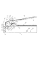
本実施形態の画像読取装置の構成を図1に示す。100は原稿給送装置である。117は画像読取装置である。101は原稿トレイであり、原稿102を積載する。原稿トレイ101の上方には、給紙ローラ103が設けられている。給紙ローラ103は原稿トレイ101上の原稿102を給紙する。給紙ローラ103は、図示しないアームに軸支されているので、アームが揺動することにより上下に移動する。給紙動作が開始されると、給紙ローラ103は下降して原稿102の上面に当接する。
The configuration of the image reading apparatus of this embodiment is shown in FIG.
ローラ105は、分離ローラ104の対向側に配置されており、分離ローラ104側に押圧されている。ローラ105は、分離ローラ104より僅かに摩擦が少ないゴム材等により構成されており、分離ローラ104と協働して、給紙ローラ103によって給紙される原稿102を1枚ずつ捌いて給紙する。
The
分離ローラ104により分離された原稿は、静止したレジストローラ対106、107のニップ部に突き当てられ、それにより、原稿の先端が揃えられる。そして、リードローラ108および従動ローラ109は、原稿を流し読みガラス116に向けて搬送する。流し読みガラス116の対向側には、プラテンローラ110が配置されている。
The document separated by the
CCD(Charge Coupled Device)ラインセンサ(以下、CCD)126は、流し読みガラス116上を搬送される原稿102の表面(一方の面)の画像を読み取る。CCD126により表面画像の読み取りが行われた原稿102は、リードローラ111および従動ローラ112によりCIS(コンタクトイメージセンサ)128へ向けて搬送される。115は流し読みガラス116からシートをすくい上げるためのジャンプ台である。CIS128の対向側には、プラテンローラ127が配置されている。
A CCD (Charge Coupled Device) line sensor (hereinafter referred to as CCD) 126 reads an image on the surface (one surface) of the original 102 conveyed on the flow reading glass 116. The
CIS128は、流し読みガラス129上を搬送される原稿102の裏面(他方の面)の画像情報を読み取る。CIS128により裏面画像の読み取りが行われた原稿102は、排紙ローラ113により排紙トレイ114に排出される。
The
画像読取装置117は、読み取られるべき原稿面に対して光を照射するランプ119、原稿102からの反射光をCCD126に導くミラー120、121、122を有する。ランプ119およびミラー120は、第1ミラー台123に取り付けられている。また、ミラー121、122は、第2ミラー台124に取り付けられている。
The
ミラー台123、124は、ワイヤ(図示せず)によって駆動モータ(図示せず)と結合され、駆動モータの回転駆動により原稿台ガラス118と平行に移動する。原稿からの反射光は、ミラー120、121、122を介してレンズ125に導かれ、レンズ125によってCCD126の受光部に結像される。CCD126は、結像した反射光を光電変換し、入射光量に応じた電気信号(アナログ信号)を出力する。
The mirror tables 123 and 124 are coupled to a drive motor (not shown) by wires (not shown), and move parallel to the
CIS128は、原稿102からの反射光を受光素子で光電変換し、入射光量に応じた電気信号(アナログ信号)を出力する。
The
上記構成を有する画像読取装置は、原稿固定読みモードと原稿流し読みモードを有する。原稿固定読みモードでは、第1ミラー台123及び第2ミラー台124を副走査方向(図中矢印方向)に移動させることにより、原稿台ガラス118上に載置された原稿が読み取られる。原稿流し読みモードでは、第1ミラー台123及び第2ミラー台124を停止させた状態で、原稿給送装置100によって原稿102を搬送させることにより、流し読みガラス116上の原稿が読み取られる。原稿流し読みモードでは、流し読みガラス129を介してCIS128により原稿102の裏面の画像も読み取られる。
The image reading apparatus having the above configuration has a document fixed reading mode and a document flow reading mode. In the fixed document reading mode, the document placed on the
図2は、本実施形態の画像読取装置のブロック図である。タイミング生成回路211及び201は、読取タイミング信号をそれぞれCCD126及びCIS128へ供給する。CCD126から出力されるアナログ信号は、A/D変換部212によりデジタル信号に変換される。A/D変換部212から出力されたデジタル信号(画像データ)は、画像処理回路213においてシェーディング補正等の画像処理が行われる。画像メモリ214には、画像処理回路213で画像処理されるべき画像データ及び画像処理回路213で画像処理された画像データが一時的に保存される。画像処理回路213において画像処理が行われた画像データは、不図示の画像形成装置に送られる。CIS128から出力されるアナログ信号は、A/D変換部202によりデジタル信号に変換される。A/D変換部202から出力されたデジタル信号(画像データ)は、画像処理回路203においてシェーディング補正等の画像処理が行われる。画像メモリ204には、画像処理回路203で画像処理されるべき画像データ及び画像処理回路203で画像処理された画像データが一時的に保存される。画像処理回路203において画像処理が行われた画像データは、上記画像形成装置に送られる。この画像形成装置は、電子写真方式やインクジェット方式により、画像読取装置117から入力された画像データに基づいた画像を用紙上に形成する。
FIG. 2 is a block diagram of the image reading apparatus of the present embodiment. The
次に、図3のフローチャートに基づいて、CCD126及びCIS128のシェーディング補正値の設定について説明する。シェーディング補正は、CCD126及びCIS128の主走査方向の読み取りばらつきを補正するものである。CPU250は、原稿給送装置100により1枚目の原稿を流し読みガラス116上へ給送させる前や、原稿を連続して100枚読み取った後に、このシェーディング補正値の設定を行う。
Next, setting of the shading correction values of the
まず、CPU250は、ミラー台駆動部222を制御することにより、ミラー台123をシェーディング基準板131の位置まで移動させる。CCD126は、ランプ119が消灯した状態で、シェーディング基準板131を読み取る(S301)。CCD126からの画像信号はA/D変換部212、画像処理回路213を介して、画像データとして画像メモリ214に一時的に記憶される。CPU250は、このときの読み取りデータに基づいてCCD126のシェーディング補正におけるオフセット補正値を決定し、画像処理回路213に設定する(S302)。ここで、オフセット補正値は、ランプ消灯時のシェーディング補正後の画像データが第1の所定値(例えば、輝度値で5)になるような、CCD126の各画素に対するオフセット補正値である。
First, the
続いて、CPU250は、CIS128に内蔵されたランプを消灯させる。CIS128は、シェーディング基準板132を読み取る(S303)。CIS128からの画像信号はA/D変換部202、画像処理回路203を介して、画像データとして画像メモリ204に一時的に記憶される。CPU250は、CCD126のシェーディング補正データと同様に、このときの読み取りデータに基づいてCIS128のシェーディング補正におけるオフセット補正値を決定し、画像処理回路203に設定する(S304)。
Subsequently, the
次に、CPU250は、ランプ駆動部221を制御することにより、ランプ119を点灯させる。CCD126はシェーディング基準板131からの反射光を読み取る(S305)。CCD126からの画像信号はA/D変換部212、画像処理回路213を介して、画像データとして画像メモリ214に一時的に記憶される。CPU250は、このシェーディング基準板131の読み取りデータに基づいて、CCD126のシェーディング補正におけるゲイン補正値を決定し、画像処理回路213に設定する(S306)。ここで、ゲイン補正値は、CCD126がシェーディング基準板を読み取ったときのシェーディング補正後の画像データが第2の所定値(例えば、輝度値で245)になるような、CCD126の各画素に対するゲイン補正値である。
Next,
続いて、CPU250は、CIS128に内蔵されている光源を点灯させ、流し読みガラス129を原稿搬送方向へ移動させることにより、流し読みガラス129に設けられたシェーディング基準板132をCIS128の読み取り位置へ移動させる。CIS128は、シェーディング基準板132からの反射光を読み取る(S307)。CIS128からの画像信号はA/D変換部202、画像処理回路203を介して、画像データとして画像メモリ204に一時的に記憶される。CPU250は、CCD126のシェーディング補正データと同様に、このシェーディング基準板の読み取りデータに基づいて、CIS128のシェーディング補正におけるゲイン補正値を決定し、画像処理回路203に設定する(S308)。
Subsequently, the
その後、画像処理回路213及び203は、CCD301及びCIS128から出力される原稿画像の画像データに対して、CPU250により設定された画素毎のゲイン調整及びオフセット調整を伴ったシェーディング補正を行う。
Thereafter, the
このように、原稿の表面画像を読み取るCCD126及び原稿の裏面画像を読み取るCIS128の各々から出力される画像データに対して、上記シェーディング補正が行われる。
As described above, the shading correction is performed on the image data output from the
次に、図4のフローチャートに基づいて、グレーチャートを用いた表裏調整について説明する。まず、調整作業者は、図5に示すような、少なくとも2つの異なる反射率の階調パッチ(グレースケール)を複数個有するグレーチャート500を原稿トレイ101に上向きかつ図5に示す副走査方向に給送されるように載置する(S401)。このグレーチャート500の各パッチの濃度は主走査方向において一様である。なお、ここでは階調パッチとして説明したが、複数の階調を有する階調画像であれば、パッチ形状以外の帯形状の画像などでもよい。
Next, front and back adjustment using a gray chart will be described based on the flowchart of FIG. First, as shown in FIG. 5, the adjustment operator faces a
CPU250は原稿給送装置100の原稿搬送駆動部220を制御することにより、グレーチャート500を給送させる。CCD126(表面読取部、第1読取手段)は、グレーチャート500を読み取る(S402)。読み取られたグレーチャート500の画像データは画像処理回路213を介して画像メモリ214に記憶される。CPU250は、画像メモリ214に記憶されたグレーチャート500の各階調パッチ部分の読取輝度値(各階調パッチ部分(例えば、100画素×100画素)の読取輝度の平均値)を読み出してメモリ251に記憶する。
The
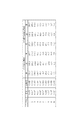
CPU250は、メモリ251に記憶された各階調パッチ部分の読取輝度値に基づいて、各階調パッチ部分の読取輝度値の主走査方向の平均値を色成分(赤、緑、青)毎に算出する(S403)。図6は、図4のステップS403において、補正用チャートを読み取ることで得られる各濃度の階調パッチに対する画像読み取り輝度値の具体例を示す図である。ここでは、図5に示すグレーチャート500の中央部の階調パッチの読み取り輝度を代表として挙げた。ここで、濃度とは、各階調パッチの測定濃度を示しており、反射率とは、次式(1)で定義される値を示している。
Based on the read luminance value of each gradation patch portion stored in the

式(1)において、Rは反射率、Dは濃度を表している。 In formula (1), R represents reflectance and D represents density.
次に、調整作業者は、グレーチャート500を原稿トレイ101に下向きかつ図5に示す副走査方向に給送されるように載置する(S404)。
Next, the adjustment operator places the
CPU250は原稿給送装置100の原稿搬送駆動部220を制御することにより、グレーチャート500を給送させる。CIS128(裏面読取部、第2読取手段)は、グレーチャート500を読み取る(S405)。読み取られたグレーチャート500の画像データは画像処理回路203を介して画像メモリ204に記憶される。CPU250は、画像メモリ204に記憶されたグレーチャート500の各階調パッチ部分の読取輝度値を読み出してメモリ251に記憶する。
The
CPU250は、メモリ251に記憶された各階調パッチ部分の読取輝度値に基づいて、各階調パッチ部分の読取輝度値の主走査方向の平均値を色成分(赤、緑、青)毎に算出し、メモリ251に記憶させる(S406)。
The
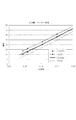
図7にCCD126及びCIS128の赤成分のリニアリティ特性を示す。横軸にグレーチャートの反射率、縦軸に読取輝度値をプロットしたものである。ここでは、赤成分のみを示しているが、緑、青も同様な傾向を示す。このように、表面読取部と裏面読取部でリニアリティ特性に差がある。そこで、表裏のリニアリティ特性の差を低減する処理を行う。
FIG. 7 shows the linearity characteristics of the red component of the
CPU250は、後述するように、CIS128(裏面読取部、第2読取手段)のゲイン調整値及びオフセット調整値を算出する(S407)。そして、CPU250は、CIS128のシェーディング補正値のゲイン調整値(傾き調整値)及びオフセット調整値(切片調整値)を画像処理回路に設定する(S408)。
As will be described later, the
ここで、図8に示すフローチャートに基づいて、ステップS407におけるCIS218(裏面読取部)のゲイン調整値及びオフセット調整値の算出について説明する。前述したように、表面読取部と裏面読取部のそれぞれのシェーディング補正値が設定されるが、このままでは表面読取部と裏面読取部の読取特性は全く独立した状態となっている。そこで、CCD126(表面読取部)及びCIS128(裏面読取部)のリニアリティ特性(原稿反射率−読取輝度特性、または階調特性)を一致させるように、裏面読取部のリニアリティ特性の調整を行う。これにより、表面読取部と裏面読取部のグレーチャートを読み取ったときの読取階調特性の相対関係を補正する。 Here, the calculation of the gain adjustment value and the offset adjustment value of the CIS 218 (back surface reading unit) in step S407 will be described based on the flowchart shown in FIG. As described above, the shading correction values of the front side reading unit and the back side reading unit are set, but the reading characteristics of the front side reading unit and the back side reading unit are completely independent as they are. Therefore, the linearity characteristics of the back side reading unit are adjusted so that the linearity characteristics (original reflectance-reading luminance characteristics or gradation characteristics) of the CCD 126 (front side reading unit) and the CIS 128 (back side reading unit) are matched. This corrects the relative relationship of the read gradation characteristics when the gray charts of the front side reading unit and the back side reading unit are read.
ここでは、中間調の階調パッチのうち、低濃度パッチ、高濃度パッチを用いて表裏読み取り輝度の合わせ込みを行う。この2つの階調パッチは、原稿反射率−読取輝度特性を直線近似することが可能な反射率を有している。ここでは、パッチNo.2(濃度0.147、反射率0.713)とパッチNo.10(濃度1.787、反射率0.016)の階調パッチの表面読取部と裏面読取部の読取輝度に基づいて、裏面読取部のリニアリティ補正を行う。 Here, among the halftone patches, the low and high density patches are used to adjust the front and back reading luminance. These two gradation patches have a reflectance capable of linearly approximating the document reflectance-reading luminance characteristic. Here, the patch No. 2 (density 0.147, reflectance 0.713) and patch no. Based on the reading luminance of the front surface reading unit and the back surface reading unit of the gradation patch of 10 (density 1.787, reflectance 0.016), the linearity correction of the back surface reading unit is performed.
まず、CPU250は、表面読取部について、メモリ251に記憶された2つの階調パッチ(パッチNo.2とパッチNo.10)の色成分毎の平均値を読み出す。そして、読み出した2点の値に基づいて、CCD126(表面読取部)の原稿反射率−読取輝度特性について、色成分毎の傾き及び切片を算出する(S801)。このCCD126の原稿反射率−読取輝度特性(リニアリティ特性)は、表面読取部と裏面読取部のリニアリティ特性をあわせるための基準とする。次に、CIS128の原稿反射率−読取輝度特性についても、CCD126と同様に、2つの階調パッチ(パッチNo.2とパッチNo.10)の色成分毎の平均値に基づいて、色成分毎の傾き及び切片を算出する(S801)。
First, the
そして、裏面読取部の各色成分のリニアリティ特性を表面読取部に合わせるように、裏面読取部のシェーディング補正値の色成分毎の調整値(ゲイン調整値及びオフセット調整値)を算出する(S802)。ゲイン調整値及びオフセット調整値の算出後、ステップS407へ戻る。
ここで、
Then, an adjustment value (gain adjustment value and offset adjustment value) for each color component of the shading correction value of the back surface reading unit is calculated so that the linearity characteristic of each color component of the back surface reading unit matches the front surface reading unit (S802). After calculating the gain adjustment value and the offset adjustment value, the process returns to step S407.
here,
とすると、ゲイン調整値a及びオフセット調整値bは次式により求めることができる。 Then, the gain adjustment value a and the offset adjustment value b can be obtained by the following equations.
上記式(2)、式(3)を用いて算出した値により、シェーディング補正データの調整を行う。具体的には、各画素のシェーディング補正データのゲイン補正値にゲイン調整値を乗算し、シェーディング補正データのオフセット補正値にオフセット調整値を加算する。その結果は、図9に示すようになる。 The formula (2), the value calculated using equation (3), intends row adjust the shading correction data. Specifically, the gain correction value of the shading correction data of each pixel is multiplied by the gain adjustment value, and the offset adjustment value is added to the offset correction value of the shading correction data. The result is as shown in FIG.
図10に、調整前後のCCD126の読取輝度値とCIS128の読取輝度値の差を示す。シェーディング補正データの表裏調整を行うことで、読み取り値の差が減少し、調整前では最大8レベル程度の差があったのに対し、調整後は最大でも3レベル程度まで改善できている。このように、高濃度部から低濃度部までの広い濃度範囲で表裏の読み取り輝度の合わせ込みができる。
FIG. 10 shows the difference between the reading luminance value of the
しかし、グレーチャートを用いた表裏調整では、グレー(中間調)の階調パッチにのみ注目して表裏調整を行うため、カラー(有彩色)の読取輝度値の表裏差が低減できない場合がある。 However, in the front / back adjustment using the gray chart, the front / back adjustment is performed while paying attention only to the gray (halftone) gradation patch, and therefore, the front / back difference in the read luminance value of the color (chromatic color) may not be reduced.
そのことを確認するために、図11に示すような、グレーのみでなく、赤緑青の基準色のカラーパッチを含んだカラーチャート(カラー基準原稿)1100を表面読取部及び裏面読取部により読み取って比較する。 In order to confirm this, a color chart (color reference document) 1100 including color patches of not only gray but also red, green and blue as shown in FIG. 11 is read by the front side reading unit and the back side reading unit. Compare.
図12は、上述したような、グレーの階調に注目して表裏の読取輝度差を低減する調整をした場合に、図11のグレーパッチを読み取った場合の色成分毎のリニアリティ特性を示す。このように、各色成分の表裏のリニアリティ特性の差が低減されている。 FIG. 12 shows the linearity characteristics for each color component when the gray patch of FIG. 11 is read when the above-described adjustment for reducing the reading luminance difference between the front and back sides is performed by paying attention to the gray gradation. Thus, the difference in the linearity characteristics between the front and back of each color component is reduced.
しかし、この表裏調整の状態で、例えば、図11の青パッチを読み取った場合、リニアリティに大きな表裏差が生じてしまうことがある。図13は、青パッチを読み取った場合の色成分毎のリニアリティ特性を示す。なお、図13において、最も低濃度の青パッチの反射率及び読取輝度値は、それぞれの色成分のグラフにおける最も低い値に対応するが、図からわかるように、各色成分の読取輝度値及び反射率は同じではない。図14は、図13のリニアリティ特性の低反射率部分を拡大して示したものである。このように、5〜6レベルの表裏差が生じており、これが表裏の色味の差となって現れてしまう。つまり、グレーチャートを用いて表裏調整を行っても、グレー以外の有彩色に関しては、表裏で読取輝度に差が発生してしまう場合がある。 However, for example, when the blue patch in FIG. 11 is read in the front-back adjustment state, a large front-back difference may occur in the linearity. FIG. 13 shows linearity characteristics for each color component when a blue patch is read. In FIG. 13, the reflectance and read luminance value of the blue patch with the lowest density correspond to the lowest values in the graph of each color component, but as can be seen from the figure, the read luminance value and reflection of each color component. The rate is not the same. FIG. 14 is an enlarged view of the low reflectance portion of the linearity characteristic of FIG. In this way, there is a front-back difference of 5 to 6 levels, and this appears as a difference in color between the front and back. That is, even if the front / back adjustment is performed using the gray chart, there may be a difference in the reading luminance between the front and back for chromatic colors other than gray.
そこで、本実施形態では、カラーチャート1100上のグレー、赤、緑、青のパッチを読み取った際の表裏差に対するそれぞれの調整値を予め作成し、原稿読み取り時の各画素の色味によって、画素毎に選択的に調整値を切り替える処理を行う。つまり、カラー基準原稿の各色相を読み取った際の表裏差に対するそれぞれの補正値を予め作成し、原稿読取時の各画素の色相によって、画素毎に選択的に補正値を切り替えて表裏補正を行う。これにより、グレー画像であるかカラー画像であるか、また、どの色成分が強いかを問わず、最適な表裏色差低減を図ることが可能となる。
Therefore, in the present embodiment, adjustment values for the front and back differences when the gray, red, green, and blue patches on the
図15のフローチャートに基づいて、カラーチャート1100による表裏調整について説明する。まず、調整作業者は、図11に示すカラーチャート(基準原稿)1100を原稿トレイ101に上向きかつ図11に示す副走査方向に給送されるように載置する(S1501)。このカラーチャート1100は、グレーパッチと赤、緑、青の色パッチを有している。このカラーチャートは、高い反射率から低い反射率まで複数の反射率のグレーパッチと色パッチを有している。なお、ここではパッチとして説明したが、パッチ形状以外の帯形状の基準画像などでもよい。
Based on the flowchart of FIG. 15, front and back adjustment by the
CPU250は原稿給送装置100の原稿搬送駆動部220を制御することにより、カラーチャート1100を給送させる。CCD126(表面読取部、第1読取手段)は、カラーチャート1100を読み取る(S1502)。読み取られたカラーチャート1100の画像データは画像処理回路213を介して画像メモリ214に記憶される。CPU250は、画像メモリ214に記憶されたカラーチャート1100の各パッチ部分の読取輝度値を読み出してメモリ251に記憶する(S1503)。
The
次に、調整作業者は、カラーチャート1100を原稿トレイ101に下向きかつ図11に示す副走査方向に給送されるように載置する(S1504)。
Next, the adjustment operator places the
CPU250は原稿給送装置100の原稿搬送駆動部220を制御することにより、カラーチャート1100を給送させる。CIS128(裏面読取部、第2読取手段)は、カラーチャート1100を読み取る(S1505)。読み取られたカラーチャート1100の画像データは画像処理回路203を介して画像メモリ204に記憶される。CPU250は、画像メモリ204に記憶されたカラーチャート1100の各パッチ部分の読取輝度値を読み出してメモリ251に記憶する(S1506)。
The
次に、CPU250は、メモリ251に記憶された各パッチ部分の読取輝度値に基づいて、グレー、赤、緑、青の各パッチを基準としたCIS128(裏面読取部、第2読取手段)のゲイン調整値及びオフセット調整値を算出する(S1507)。そして、CPU250は、CIS128のシェーディング補正値の調整値として、グレー、赤、緑、青に対するそれぞれのゲイン調整値及びオフセット調整値を画像処理回路に設定する(S1508)。
Next, the
裏面読取部の調整値の算出は、前述した図8のフローチャートに従った処理により行う。すなわち、グレー、赤、緑、青のそれぞれのパッチについて、低濃度パッチ(パッチNo.1)と高濃度パッチ(パッチNo.10)から表面読取部と裏面読取部の原稿反射率−読取輝度特性(リニアリティ特性)を求める。そして、裏面読取部の各色成分のリニアリティ特性を表面読取部に合わせるように、裏面読取部のシェーディング補正値の色成分毎の調整値(ゲイン調整値及びオフセット調整値)を算出する。そして、CPU250により、グレー、赤、緑、青に対するそれぞれのゲイン調整値及びオフセット調整値が画像処理回路203に設定される。なお、この処理は、CPU250の代わりに、工場に設置されたコンピュータによりCPU250を介して実行されてもよい。
The calculation of the adjustment value of the back side reading unit is performed by the process according to the flowchart of FIG. That is, for each of the gray, red, green, and blue patches, the original reflectance-read luminance characteristics of the front side reading unit and the back side reading unit from the low density patch (patch No. 1) and the high density patch (patch No. 10). (Linearity characteristics) is obtained. Then, an adjustment value (gain adjustment value and offset adjustment value) for each color component of the shading correction value of the back surface reading unit is calculated so that the linearity characteristic of each color component of the back surface reading unit matches that of the front surface reading unit. The
次に、画像読取装置117により原稿を読み取る際における、画像処理回路203でのシェーディング補正処理について図16を用いて説明する。前述したように、原稿の表面及び裏面の画像は、それぞれCCD126及びCIS128により読み取られる。CIS128からの画像信号はA/D変換部202を介して画像処理回路203に入力される。画像処理回路203は、注目画素位置を先頭位置とする初期化を行った上で(S1601)、注目画素の各色成分の読取輝度値をR、G、Bとする(S1602)。
Next, shading correction processing in the
そして、R−Gが30よりも大きく、かつ、R−Bが30よりも大きい場合は(S1603)、赤に対するゲイン調整値及びオフセット調整値によりシェーディング補正値(ゲイン補正値及びオフセット補正値)を調整する(S1604)。G−Rが30よりも大きく、かつ、G−Bが30よりも大きい場合は(S1605)、緑に対するゲイン調整値及びオフセット調整値によりシェーディング補正値(ゲイン補正値及びオフセット補正値)を調整する(S1606)。B−Rが30よりも大きく、かつ、B−Gが30よりも大きい場合は(S1607)、青に対するゲイン調整値及びオフセット調整値によりシェーディング補正値(ゲイン補正値及びオフセット補正値)を調整する(S1608)。 If RG is larger than 30 and RB is larger than 30 (S1603), a shading correction value (gain correction value and offset correction value) is obtained from the gain adjustment value and offset adjustment value for red. Adjust (S1604). When GR is larger than 30 and GB is larger than 30 (S1605), the shading correction value (gain correction value and offset correction value) is adjusted by the gain adjustment value and offset adjustment value for green. (S1606). When BR is larger than 30 and BG is larger than 30 (S1607), the shading correction value (gain correction value and offset correction value) is adjusted by the gain adjustment value and offset adjustment value for blue. (S1608).
ステップS1603、S1605、S1607のいずれにも該当しない場合は、グレーに対するゲイン調整値及びオフセット調整値によりシェーディング補正値(ゲイン補正値及びオフセット補正値)を調整する(S1609)。赤、緑、青、グレーに対するゲイン調整値及びオフセット調整値は、図15のS1508の処理により予め設定された値である。 If none of the steps S1603, S1605, and S1607 is applicable, the shading correction value (gain correction value and offset correction value) is adjusted by the gain adjustment value and offset adjustment value for gray (S1609). The gain adjustment value and the offset adjustment value for red, green, blue, and gray are values set in advance by the processing of S1508 in FIG.
そして、調整されたシェーディング補正値に基づいて、注目画素の読取データのシェーディング補正処理を行い、シェーディング補正された画像データを画像形成装置へ出力する(S1610)。注目画素位置が末尾位置(原稿の読取終了)でない場合は(S1611)、注目画素位置を1画素移動させて(S1612)、ステップS1602へ戻る。ステップS1611で注目画素位置が末尾位置である場合は処理を終了する。 Then, based on the adjusted shading correction value, shading correction processing of the read data of the target pixel is performed, and the image data subjected to the shading correction is output to the image forming apparatus (S1610). If the target pixel position is not the end position (end of document reading) (S1611), the target pixel position is moved by one pixel (S1612), and the process returns to step S1602. If the target pixel position is the end position in step S1611, the process ends.
上述した画像処理回路203の処理により、青の階調部のリニアリティ特性差を改善したグラフを図17に示す。このように、例えば、原稿画像中に青色部分がある場合、青色画像を読み取ったときの表裏のリニアリティ特性差を軽減した補正処理を行うことができる。従って、原稿画像中に存在するそれぞれの色味にあわせて、画素毎に表裏のリニアリティ特性差を軽減することが可能となる。
FIG. 17 shows a graph in which the linearity characteristic difference of the blue gradation portion is improved by the processing of the
なお、本実施形態では、ステップS1603、S1605、S1607において、30を目安に調整値を切り替えているが、ここで示した値は一例であり、装置の特性に応じて他の値としてもよい。また、本実施形態では、カラーチャートのパッチは赤、緑、青の基準色とグレーであったが複数色の色パッチであればよく、シアン、マゼンダ、イエローの基準色とグレーでもよい。また、色味管理を厳密に行いたい色などのパッチを加えても良く、如何なる色にも応用可能である。また、本実施形態では4つの調整値のいずれかを選択するようにしているが、4つよりも少ない調整値(調整対象色)や4つよりも多い調整値(調整対象色)としてもよい。 In this embodiment, the adjustment value is switched using 30 as a guide in steps S1603, S1605, and S1607. However, the value shown here is an example, and other values may be used according to the characteristics of the apparatus. In this embodiment, the color chart patches are red, green, and blue reference colors and gray, but may be multi-color patches, and may be cyan, magenta, and yellow reference colors and gray. Further, a patch such as a color for which color management is strictly required may be added, and the present invention can be applied to any color. In the present embodiment, any one of the four adjustment values is selected. However, fewer adjustment values (adjustment target colors) than four adjustment values or adjustment values larger than four (adjustment target colors) may be used. .
本実施形態では、表面読み取りにCCD126(縮小光学系)、裏面読み取りにCIS128(等倍光学系)を使用した場合を説明したが、表面読み取りにCIS128を、裏面読み取りにCCD126を採用してもよい。また、表面及び裏面読取部を同種のイメージセンサとした場合にも、応用可能である。
In the present embodiment, the case where the CCD 126 (reduction optical system) is used for front side reading and the CIS128 (equal magnification optical system) is used for back side reading has been described. However, the
さらに、画像読み取りに用いるイメージセンサは、CCD126やCIS128に限定されるものではなく、例えばCMOSイメージセンサであってもよい。
Furthermore, the image sensor used for image reading is not limited to the
また、図11のカラーチャート1100は主走査方向にグレー、赤、緑、青パッチが配列されたものであったが、主走査方向に同じ色のパッチを配列したカラーチャートを読み取って、上述と同様の処理を行ってもよい。これにより、主走査方向の読み取り特性差を軽減することが可能となる。
Further, the
また、上述した実施形態では、低濃度パッチと高濃度パッチの2つのパッチによりリニアリティ特性を求めたが、3つ以上のパッチによりリニアリティ特性を求めるようにしてもよい。例えば、図18に示すように、ポイント1〜4に対応する反射率のパッチの読取輝度値に基づいて、3つの区間のリニアリティ特性(ゲイン1〜3)を求めるようにしてもよい。また、同じ濃度のパッチであっても、原稿面の状態(原稿の表面性)、つまり、原稿面に光沢がある場合と、原稿面に光沢がない場合とによって、読み取り特性が異なるため、原稿面の状態に応じて調整するようにしてもよい。この場合、原稿種に応じて、光沢あり原稿、オフセット印刷原稿、電子写真原稿、光沢なし原稿それぞれに対応した表裏調整値を、前述した実施形態と同様に予め設定しておく。そして、原稿読取時にユーザにより原稿種を操作部から入力させることにより、調整値を選択することで、原稿種に応じた表裏調整が可能となる。
In the above-described embodiment, the linearity characteristic is obtained from two patches, a low density patch and a high density patch, but the linearity characteristic may be obtained from three or more patches. For example, as shown in FIG. 18, the linearity characteristics (
上述した実施形態では、裏面読取部のリニアリティ特性を表面読取部のリニアリティ特性に合わせたが、表面読取部のリニアリティ特性を裏面読取部のリニアリティ特性に合わせるようにしてもよい。また、表面読取部と裏面読取部のリニアリティ特性それぞれを調整して、表裏のリニアリティ特性を合わせるようにしてもよい。これにより、表面読取部と裏面読取部のカラーチャートを読み取ったときの読取階調特性の相対関係を補正する。 In the above-described embodiment, the linearity characteristic of the back side reading unit is matched with the linearity characteristic of the front side reading unit. However, the linearity characteristic of the front side reading unit may be matched with the linearity characteristic of the back side reading unit. Alternatively, the linearity characteristics of the front side reading unit and the back side reading unit may be adjusted to match the front and back linearity characteristics. Thereby, the relative relationship of the read gradation characteristics when the color charts of the front side reading unit and the back side reading unit are read is corrected.
また、上述した実施形態では、画像読取装置が表裏調整を行うように説明したが、表裏調整処理については、画像読取装置に接続されたパーソナルコンピュータや画像形成装置が行うようにしてもよい。この場合、画像処理回路203及び213と同等の機能を画像形成装置やパーソナルコンピュータに備えている。画像形成装置やパーソナルコンピュータは、画像読取装置が読み取ったチャートの画像データを受け取り、この画像データに基づいて、前述した算出及び調整に関する処理を行う。この処理を実行するためのプログラムは、ハードディスクやCD−ROM等の記憶媒体に記憶されており、画像形成装置やパーソナルコンピュータのCPUにより読み取られ、実行される。
In the above-described embodiment, the image reading apparatus performs the front / back adjustment. However, the front / back adjustment processing may be performed by a personal computer or an image forming apparatus connected to the image reading apparatus. In this case, the image forming circuit and the personal computer have functions equivalent to those of the
100 原稿給送装置
117 画像読取装置
126 CCD
128 CIS
150 操作部
203、213 画像処理回路
250 CPU
100
128 CIS
150
Claims (2)
前記原稿の他方の面を読み取る第2読取手段と、
照明点灯時および消灯時それぞれにおける第1基準部材の前記第1読取手段による読取値からゲイン値およびオフセット値である前記第1読取手段の第1シェーディングデータを生成し、照明点灯時および消灯時それぞれにおける第2基準部材の前記第2読取手段による読取値からゲイン値およびオフセット値である前記第2読取手段の第2シェーディングデータを生成するシェーディングデータ生成手段と、
複数の異なる色のパッチを有するカラーチャートを前記第1読取手段で読み取った読取値と、前記カラーチャートを前記第2読取手段で読み取った読取値とから、前記複数の異なる色に対応する複数のシェーディングデータ補正値を生成するシェーディングデータ補正値生成手段と、
前記第1シェーディングデータを用いて、前記第1読取手段から出力された前記原稿の一方の面の読取値を補正する第1補正手段と、
前記第2読取手段から出力された前記原稿の他方の面の読取値の色を識別し、前記複数のシェーディングデータ補正値から該識別結果に応じたシェーディングデータ補正値を選択し、該選択されたシェーディング補正値を用いて前記第2シェーディングデータを補正し、該補正された第2シェーディングデータを用いて前記原稿の他方の面の読取値を補正する第2補正手段とを有することを特徴とする原稿読取装置。 First reading means for reading one side of the document;
Second reading means for reading the other side of the document;
First shading data of the first reading means, which is a gain value and an offset value, is generated from reading values of the first reference member by the first reading means when the illumination is turned on and off, respectively. Shading data generating means for generating second shading data of the second reading means that is a gain value and an offset value from reading values of the second reference member by the second reading means;
A plurality of colors corresponding to the plurality of different colors from a reading value obtained by reading the color chart having a plurality of different color patches by the first reading unit and a reading value obtained by reading the color chart by the second reading unit. A shading data correction value generating means for generating a shading data correction value;
First correction means for correcting a read value of one side of the document output from the first reading means using the first shading data;
The color of the reading value of the other side of the document output from the second reading unit is identified, and a shading data correction value corresponding to the identification result is selected from the plurality of shading data correction values, and the selected And a second correction unit that corrects the second shading data using a shading correction value, and corrects the read value of the other side of the document using the corrected second shading data. Document reader.
Priority Applications (2)
| Application Number | Priority Date | Filing Date | Title |
|---|---|---|---|
| JP2007172744A JP4948291B2 (en) | 2007-06-29 | 2007-06-29 | Document reader |
| US12/147,300 US8164808B2 (en) | 2007-06-29 | 2008-06-26 | Image reading device and reading-characteristic correction method for image reading device |
Applications Claiming Priority (1)
| Application Number | Priority Date | Filing Date | Title |
|---|---|---|---|
| JP2007172744A JP4948291B2 (en) | 2007-06-29 | 2007-06-29 | Document reader |
Publications (3)
| Publication Number | Publication Date |
|---|---|
| JP2009010887A JP2009010887A (en) | 2009-01-15 |
| JP2009010887A5 JP2009010887A5 (en) | 2010-08-12 |
| JP4948291B2 true JP4948291B2 (en) | 2012-06-06 |
Family
ID=40160060
Family Applications (1)
| Application Number | Title | Priority Date | Filing Date |
|---|---|---|---|
| JP2007172744A Expired - Fee Related JP4948291B2 (en) | 2007-06-29 | 2007-06-29 | Document reader |
Country Status (2)
| Country | Link |
|---|---|
| US (1) | US8164808B2 (en) |
| JP (1) | JP4948291B2 (en) |
Families Citing this family (9)
| Publication number | Priority date | Publication date | Assignee | Title |
|---|---|---|---|---|
| JP4812106B2 (en) * | 2006-12-05 | 2011-11-09 | キヤノン株式会社 | Image reading apparatus and control method thereof |
| JP4977567B2 (en) * | 2007-09-27 | 2012-07-18 | 京セラドキュメントソリューションズ株式会社 | Image reading apparatus and image forming apparatus |
| JP2010074342A (en) * | 2008-09-17 | 2010-04-02 | Fuji Xerox Co Ltd | Image processing apparatus, image forming apparatus, and program |
| JP2010199747A (en) * | 2009-02-23 | 2010-09-09 | Canon Inc | Image processing apparatus, spatial frequency conversion method for image processing apparatus, and program |
| JP5484085B2 (en) * | 2010-01-18 | 2014-05-07 | キヤノン株式会社 | Image forming apparatus and image quality correction method thereof |
| JP6257219B2 (en) * | 2013-08-23 | 2018-01-10 | キヤノン株式会社 | Image reading device |
| JP2017079374A (en) * | 2015-10-19 | 2017-04-27 | 株式会社リコー | Image reading device, image forming apparatus, and shading data processing method |
| JP6849322B2 (en) * | 2016-06-01 | 2021-03-24 | キヤノン株式会社 | Image reader, image forming device |
| JP7073783B2 (en) * | 2018-02-28 | 2022-05-24 | 富士フイルムビジネスイノベーション株式会社 | Image processing equipment and programs |
Family Cites Families (10)
| Publication number | Priority date | Publication date | Assignee | Title |
|---|---|---|---|---|
| JP2622039B2 (en) * | 1991-06-20 | 1997-06-18 | 株式会社ピーエフユー | Reading density correction method for double-sided image scanner |
| JP3715794B2 (en) * | 1998-09-08 | 2005-11-16 | キヤノン株式会社 | Image reading apparatus and method for controlling image reading apparatus |
| JP3660180B2 (en) | 1999-11-26 | 2005-06-15 | シャープ株式会社 | Image processing device |
| JP2003032504A (en) * | 2001-07-16 | 2003-01-31 | Ricoh Co Ltd | Image forming device |
| JP2003219172A (en) * | 2002-01-18 | 2003-07-31 | Canon Inc | Image processing apparatus and image forming apparatus |
| JP2004072536A (en) * | 2002-08-07 | 2004-03-04 | Nisca Corp | Image reader, image reading method and original transporting device |
| JP2004187144A (en) | 2002-12-05 | 2004-07-02 | Canon Inc | Image reading apparatus |
| JP4367079B2 (en) * | 2003-10-14 | 2009-11-18 | 富士ゼロックス株式会社 | Image reading device |
| JP4432504B2 (en) | 2004-01-21 | 2010-03-17 | 富士ゼロックス株式会社 | Image reading device |
| JP4188925B2 (en) * | 2005-02-16 | 2008-12-03 | シャープ株式会社 | Document reading apparatus, image forming apparatus including the same, and method for adjusting document reading apparatus |
-
2007
- 2007-06-29 JP JP2007172744A patent/JP4948291B2/en not_active Expired - Fee Related
-
2008
- 2008-06-26 US US12/147,300 patent/US8164808B2/en not_active Expired - Fee Related
Also Published As
| Publication number | Publication date |
|---|---|
| US8164808B2 (en) | 2012-04-24 |
| US20090002784A1 (en) | 2009-01-01 |
| JP2009010887A (en) | 2009-01-15 |
Similar Documents
| Publication | Publication Date | Title |
|---|---|---|
| JP4948291B2 (en) | Document reader | |
| JP4310351B2 (en) | Image reading apparatus and reading characteristic correction method for image reading apparatus | |
| US7626735B2 (en) | Image reading apparatus for correcting images on both sides of a document sheet | |
| JP5558687B2 (en) | Image reading device | |
| US7123390B2 (en) | Image scanner | |
| US8259370B2 (en) | Image reading device having line sensor performing pre-scan based on condition set for main-scan | |
| US8537418B2 (en) | Image processing device, image forming apparatus incorporating same, image processing method used in the image forming apparatus, and program product used in the image forming apparatus | |
| JP5233625B2 (en) | Image reading apparatus and image forming apparatus | |
| US8068260B2 (en) | Original document size detection using a line sensor for reading the original document | |
| US8218196B2 (en) | Image processing method and image processing apparatus | |
| US20080088887A1 (en) | Image reading apparatus and method for adjusting same | |
| US8422086B2 (en) | Image processing apparatus and method using different scaling methods for scanning | |
| US20100134858A1 (en) | Image scanning device and calibration method thereof | |
| JP5694710B2 (en) | Document reader | |
| US10250773B2 (en) | Image reading device, method of adjusting distance between document and light receiving sensor in the device, and distance adjustment program | |
| JP4989121B2 (en) | Image reading device | |
| JP2021057866A (en) | Image reading device and control method of the same | |
| JP2012151644A (en) | Image reader, image formation apparatus provided with image reader, and image processing method | |
| US11601566B2 (en) | Image reading device, image reading program, image processing device, and image processing program | |
| US11394842B2 (en) | Image reading apparatus determines whether a document is chromatic or achromatic and performing a conveyance speed of a document based on the setting of a color determination, and performing conveyance speed based on setting of an output resolution without setting whether to perform a color determination | |
| JP5245883B2 (en) | Image processing apparatus, image forming apparatus, image processing method, and program | |
| JP2016092655A (en) | Image reader and image formation device | |
| JP2018160849A (en) | Reading device and control method | |
| JP2018007027A (en) | Image reading device, distance adjustment method for document and light-receiving sensor in the device, and distance adjustment program | |
| JP2006254149A (en) | Image reading device and image forming apparatus |
Legal Events
| Date | Code | Title | Description |
|---|---|---|---|
| RD04 | Notification of resignation of power of attorney |
Free format text: JAPANESE INTERMEDIATE CODE: A7424 Effective date: 20100201 |
|
| A521 | Written amendment |
Free format text: JAPANESE INTERMEDIATE CODE: A523 Effective date: 20100623 |
|
| A621 | Written request for application examination |
Free format text: JAPANESE INTERMEDIATE CODE: A621 Effective date: 20100623 |
|
| RD01 | Notification of change of attorney |
Free format text: JAPANESE INTERMEDIATE CODE: A7421 Effective date: 20100713 |
|
| A977 | Report on retrieval |
Free format text: JAPANESE INTERMEDIATE CODE: A971007 Effective date: 20110725 |
|
| A131 | Notification of reasons for refusal |
Free format text: JAPANESE INTERMEDIATE CODE: A131 Effective date: 20110823 |
|
| A521 | Written amendment |
Free format text: JAPANESE INTERMEDIATE CODE: A523 Effective date: 20111024 |
|
| TRDD | Decision of grant or rejection written | ||
| A01 | Written decision to grant a patent or to grant a registration (utility model) |
Free format text: JAPANESE INTERMEDIATE CODE: A01 Effective date: 20120207 |
|
| A01 | Written decision to grant a patent or to grant a registration (utility model) |
Free format text: JAPANESE INTERMEDIATE CODE: A01 |
|
| A61 | First payment of annual fees (during grant procedure) |
Free format text: JAPANESE INTERMEDIATE CODE: A61 Effective date: 20120306 |
|
| FPAY | Renewal fee payment (event date is renewal date of database) |
Free format text: PAYMENT UNTIL: 20150316 Year of fee payment: 3 |
|
| FPAY | Renewal fee payment (event date is renewal date of database) |
Free format text: PAYMENT UNTIL: 20150316 Year of fee payment: 3 |
|
| LAPS | Cancellation because of no payment of annual fees |