JP4942203B2 - Electronics - Google Patents

Electronics Download PDF

Info

Publication number
JP4942203B2
JP4942203B2 JP2007328182A JP2007328182A JP4942203B2 JP 4942203 B2 JP4942203 B2 JP 4942203B2 JP 2007328182 A JP2007328182 A JP 2007328182A JP 2007328182 A JP2007328182 A JP 2007328182A JP 4942203 B2 JP4942203 B2 JP 4942203B2
Authority
JP
Japan
Prior art keywords
main body
state
control unit
belt
use position
Prior art date
Legal status (The legal status is an assumption and is not a legal conclusion. Google has not performed a legal analysis and makes no representation as to the accuracy of the status listed.)
Expired - Fee Related
Application number
JP2007328182A
Other languages
Japanese (ja)
Other versions
JP2009152337A (en
JP2009152337A5 (en
Inventor
洋 細江
Current Assignee (The listed assignees may be inaccurate. Google has not performed a legal analysis and makes no representation or warranty as to the accuracy of the list.)
Canon Inc
Original Assignee
Canon Inc
Priority date (The priority date is an assumption and is not a legal conclusion. Google has not performed a legal analysis and makes no representation as to the accuracy of the date listed.)
Filing date
Publication date
Application filed by Canon Inc filed Critical Canon Inc
Priority to JP2007328182A priority Critical patent/JP4942203B2/en
Publication of JP2009152337A publication Critical patent/JP2009152337A/en
Publication of JP2009152337A5 publication Critical patent/JP2009152337A5/ja
Application granted granted Critical
Publication of JP4942203B2 publication Critical patent/JP4942203B2/en
Expired - Fee Related legal-status Critical Current
Anticipated expiration legal-status Critical

Links

Images

Landscapes

  • Camera Bodies And Camera Details Or Accessories (AREA)
  • Accessories Of Cameras (AREA)
  • Casings For Electric Apparatus (AREA)
  • Studio Devices (AREA)

Description

本発明は、電子機器、より具体的には手持ち状態で使用される電子機器に関する。   The present invention relates to an electronic device, and more specifically to an electronic device used in a handheld state.

ビデオカメラなどの携帯電子機器は、機器使用時に手で把持した状態を補助する、グリップベルトやリストストラップなどと呼ばれる把持補助手段を備えている。このような把持補助手段により、把持の安定性を高め、また、不用意な落下を防止できる。   A portable electronic device such as a video camera is provided with a grip assisting means called a grip belt or a wrist strap that assists the hand gripped state when the device is used. Such grip assisting means can increase gripping stability and prevent inadvertent dropping.

図29は、従来のビデオカメラ210の外観斜視図を示し、図30は別の方角から見たビデオカメラ210の外観斜視図を示す。滑らかな曲面で形成された把持部212に、電源スイッチ214など操作部材を配置している。図31は、グリップベルト216の補助下に撮影者がビデオカメラ210を把持している状態を示す。   FIG. 29 shows an external perspective view of a conventional video camera 210, and FIG. 30 shows an external perspective view of the video camera 210 viewed from another direction. An operation member such as a power switch 214 is arranged on the grip portion 212 formed with a smooth curved surface. FIG. 31 shows a state where the photographer is holding the video camera 210 with the assistance of the grip belt 216.

グリップベルト216の一端は、把持部に設けた固定部218に接続し、他端は、ビデオカメラ210の前方に設けた通し環220をくぐらせたのち、甲当て部222に設けた面ファスナーで固定する。面ファスナーは、ベルト長手方向に十分な長さをもって配設する。面ファスナーを貼り合わせる位置により、使用者の手の幅や厚みに応じた調整が可能となる。使用者は、自身の手に合わせてグリップベルト216の長さを調節し、その補助によりビデオカメラ210の本体をしっかりと安定的に把持できる。   One end of the grip belt 216 is connected to a fixing portion 218 provided in the gripping portion, and the other end is a hook-and-loop fastener provided in the back support portion 222 after passing through a through ring 220 provided in front of the video camera 210. Fix it. The hook-and-loop fastener is provided with a sufficient length in the belt longitudinal direction. Adjustment according to the width and thickness of the user's hand is possible depending on the position where the surface fastener is attached. The user adjusts the length of the grip belt 216 according to his / her hand, and with the assistance, the user can firmly and stably hold the main body of the video camera 210.

また、図32に示すように、肩掛けベルト224を装着することで、カメラ非使用時に肩に掛けて運ぶことができる。肩掛けベルト224は、運搬の補助として有用であるが、撮影時には邪魔となり取り回しが不便である。また、カメラを撮影姿勢に持ち替える必要があり、不意に遭遇した撮影チャンスを逃す恐れがある。   Also, as shown in FIG. 32, by wearing a shoulder belt 224, it can be carried on the shoulder when the camera is not used. The shoulder belt 224 is useful as an aid for transportation, but it is an inconvenience in handling because it is an obstacle during photographing. In addition, it is necessary to change the camera to a shooting posture, and there is a risk of missing a shooting opportunity that was unexpectedly encountered.

一方、一つの保持ベルトの本体に対する取り付け位置を変更可能とすることで、使用時(撮影時)と携帯時とで、使用者は、それぞれに適した状態で本体を保持できる。特許文献1には、電子機器のストラップの取り付け位置を、持ち運ぶための位置と機器使用時のための位置とに変更可能とした構成が記載されている。特許文献2には、携帯する場合にはハンドストラップとして機能し、撮影時にはグリップストラップとして機能するストラップを持つ電子機器が記載されている。
特開2000−196246号公報 特開2001−330885号公報
On the other hand, by making it possible to change the attachment position of one holding belt with respect to the main body, the user can hold the main body in a state suitable for each use (when shooting) and when carrying. Patent Document 1 describes a configuration in which the attachment position of the strap of the electronic device can be changed between a position for carrying and a position for using the device. Patent Document 2 describes an electronic device having a strap that functions as a hand strap when being carried and functions as a grip strap when photographing.
JP 2000-196246 A JP 2001-330885 A

特許文献1,2に記載の構成はいずれも、使用時と携帯時とで機器を持ち替えてストラップの取り付け位置を変更する作業が必要であり、煩雑である。また、ベルトないしストラップの位置を変更する際に機器を持ち替える必要があるので、携帯状態と使用状態との間の移行を素早く行えない。   Each of the configurations described in Patent Documents 1 and 2 is cumbersome because it requires an operation of changing the attachment position of the strap by changing the device between use and carrying. Further, since it is necessary to change the device when changing the position of the belt or strap, it is not possible to quickly change between the portable state and the used state.

本発明は、使用状態から携帯状態への移行およびその逆を簡便に行える電子機器を提示することを目的とする。   An object of this invention is to show the electronic device which can perform the transition from a use state to a carrying state and vice versa simply.

上記課題を解決するために、本発明に係る電子機器は、本体の把持を補助する把持ベルトと、前記把持ベルトを前記本体に接続する接続部材であって、前記本体を使用者の手の平側と手の甲側の間でスライド及び回動の何れかにより移動可能な接続部材とを具備することを特徴とする。 In order to solve the above-described problems, an electronic device according to the present invention includes a grip belt that assists in gripping a main body, and a connecting member that connects the grip belt to the main body, the main body being connected to a palm side of a user's hand. And a connecting member movable between the back side of the hand by either sliding or turning .

本発明によれば、持ち替え無しで携帯時の把持位置と使用時の把持位置を切り替えることができ、利便性が向上する。また、把持位置に応じて本体の動作を制御することで、使用者の手間を軽減でき、誤動作も防げる。   According to the present invention, it is possible to switch between a gripping position when carried and a gripping position when in use without having to change, and convenience is improved. Further, by controlling the operation of the main body according to the gripping position, it is possible to reduce the trouble of the user and prevent malfunction.

以下、図面を参照して、本発明の実施例を詳細に説明する。   Hereinafter, embodiments of the present invention will be described in detail with reference to the drawings.

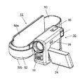
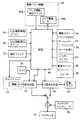
図1は、本発明に係る電子機器の一実施例であるビデオカメラの斜め正面から見た外観斜視図を示し、図2は、別の方向からみた外観斜視図を示す。本体10の側面に、リング状のグリップベルト12が取り付けられている。図3は、本体10のみを背面方向から見た外観斜視図を示す。図4は、本体10に収容される回路部品の機能ブロック図を示す。図5は、グリップベルト12のみの斜視図を示す。図6及び図7は、それぞれ異なる方向から見た、グリップベルト12の分解斜視図を示す。   FIG. 1 shows an external perspective view of a video camera as an embodiment of the electronic apparatus according to the present invention as seen from an oblique front, and FIG. 2 shows an external perspective view from another direction. A ring-shaped grip belt 12 is attached to the side surface of the main body 10. FIG. 3 shows an external perspective view of only the main body 10 as seen from the back side. FIG. 4 is a functional block diagram of circuit components housed in the main body 10. FIG. 5 shows a perspective view of only the grip belt 12. 6 and 7 are exploded perspective views of the grip belt 12 as seen from different directions.

カメラユニット14は、撮像光学系による光学像を電気信号に変換する撮像素子を具備する。信号処理回路16は、カメラユニット14からの画像信号にマイク18からの音声信号を混合して、所定形式の映像音声信号を生成する。記録再生処理回路20は、記録モードにおいて、信号処理回路16からの映像音声信号を記録メモリ22に記録し、再生モードでは、記録メモリ22に記録される映像音声信号を再生する。   The camera unit 14 includes an imaging element that converts an optical image obtained by the imaging optical system into an electrical signal. The signal processing circuit 16 mixes the audio signal from the microphone 18 with the image signal from the camera unit 14 to generate a video / audio signal in a predetermined format. The recording / playback processing circuit 20 records the video / audio signal from the signal processing circuit 16 in the recording memory 22 in the recording mode, and plays back the video / audio signal recorded in the recording memory 22 in the playback mode.

LCDモニタ24は、信号処理回路16からの映像信号または記録再生処理回路20からの再生映像信号にキャラクタジェネレータ26で生成されたキャラクタ情報を重畳した画像信号を、画像表示する。スピーカ28は、記録再生処理回路20からの音声信号を音出力する。   The LCD monitor 24 displays an image signal in which the character information generated by the character generator 26 is superimposed on the video signal from the signal processing circuit 16 or the reproduced video signal from the recording / reproducing processing circuit 20. The speaker 28 outputs the sound signal from the recording / playback processing circuit 20 as a sound.

本体10には、種々の操作スイッチ30〜38が設けられている。電源スイッチ30は、本体10の電源をオン/オフするのに使用される。トリガースイッチ32は、撮影画像の記録開始と停止を制御部40に指示するのに使用される。ズームレバー34は、撮影画角の変更を制御部40に指示するのに使用される。モード切替えボタン36は、本体10の動作モードの切り替えを制御部40に指示するのに使用される。設定ボタン38は、その他の各種動作設定を制御部40に指示するのに使用される。   The main body 10 is provided with various operation switches 30 to 38. The power switch 30 is used to turn on / off the power of the main body 10. The trigger switch 32 is used to instruct the control unit 40 to start and stop recording of a captured image. The zoom lever 34 is used to instruct the control unit 40 to change the shooting angle of view. The mode switching button 36 is used to instruct the control unit 40 to switch the operation mode of the main body 10. The setting button 38 is used to instruct the control unit 40 to perform other various operation settings.

制御部40は、各部の動作状態を監視し、その結果及び操作スイッチ30〜38の操作に応じて、各部の動作を制御する。   The control unit 40 monitors the operation state of each unit, and controls the operation of each unit according to the result and the operation of the operation switches 30 to 38.

LCDモニタ24は、ヒンジ機構42(図3)を介して本体10の側面に取り付けられている。ヒンジ機構42は、LCDモニタ24を開閉自在とする開閉軸と、当該開閉軸に直交する軸を中心として回転自在にLCDモニタ24を保持する回転軸の2軸を備える。この構造により、LCDモニタ24は、本体10に対して2軸で画面の向きを変更できる。具体的には、LCDモニタ24を画面側が本体に向くように閉じた収納状態と、画面を本体10の背後の使用者側に向けて開いた撮影状態(図1)と、画面を被写体側に向けた対面撮影状態と、画面を外側に向けて本体10に密着させた反転収納状態を実現できる。このような2軸ヒンジ機構42自体は、周知である。   The LCD monitor 24 is attached to the side surface of the main body 10 via a hinge mechanism 42 (FIG. 3). The hinge mechanism 42 includes two axes: an opening / closing axis that allows the LCD monitor 24 to be opened and closed, and a rotation axis that holds the LCD monitor 24 so as to be rotatable about an axis orthogonal to the opening / closing axis. With this structure, the LCD monitor 24 can change the orientation of the screen in two axes with respect to the main body 10. Specifically, the storage state in which the LCD monitor 24 is closed so that the screen side faces the main body, the photographing state in which the screen is opened toward the user side behind the main body 10 (FIG. 1), and the screen on the subject side. The facing facing photographing state and the inverted storage state in which the screen is directed to the outside and in close contact with the main body 10 can be realized. Such a biaxial hinge mechanism 42 itself is well known.

更に、開閉検知スイッチ44は、開閉軸を中心軸とするLCDモニタ24の開閉角度を検知する。回転検知スイッチ46は、回転軸を中心軸とするLCDモニタ24の回転角度を検知する。検知スイッチ44,46は、検知角度を示す信号を制御部40に送出する。制御部40は、これらの信号に従いLCDモニタ24の姿勢、即ち画面の方向を判別でき、LCDモニタ24の姿勢に従い、以下に述べるようにLCDモニタ24のバックライトの消灯と、画像の反転表示などを制御する。   Further, the open / close detection switch 44 detects the open / close angle of the LCD monitor 24 with the open / close axis as the central axis. The rotation detection switch 46 detects the rotation angle of the LCD monitor 24 about the rotation axis. The detection switches 44 and 46 send a signal indicating the detection angle to the control unit 40. The control unit 40 can determine the orientation of the LCD monitor 24 according to these signals, that is, the direction of the screen. According to the orientation of the LCD monitor 24, the backlight of the LCD monitor 24 is turned off and the image is inverted as described below. To control.

例えば、収納状態では、制御部40は、LCDモニタ24を消灯状態にする。使用者が図2及び図3に示すようにLCDモニタ24を開くと、LCDモニタ24のバックライトを点灯し、画像表示状態(画像信号が入力すれば画像を表示する状態)にする。また、対面撮影状態では、制御部40は、LCDモニタ24に画像を上下反転で表示させる。これにより、被写体方向から被写体を鏡像として鑑賞できる。対面撮影状態でLCDモニタ24を本体10に密着させると、反転収納状態となる。この反転収納状態では、制御部40は、LCDモニタ24に画像を左右反転で表示させる。これにより、LCDモニタ24の表示画像は、使用者にとって正立像になる。   For example, in the storage state, the control unit 40 turns off the LCD monitor 24. When the user opens the LCD monitor 24 as shown in FIG. 2 and FIG. 3, the backlight of the LCD monitor 24 is turned on to enter an image display state (a state in which an image is displayed when an image signal is input). In the face-to-face shooting state, the control unit 40 causes the LCD monitor 24 to display an image upside down. Thereby, the subject can be viewed as a mirror image from the subject direction. When the LCD monitor 24 is brought into close contact with the main body 10 in the face-to-face shooting state, a reverse storage state is obtained. In this inverted storage state, the control unit 40 causes the LCD monitor 24 to display the image in a horizontally reversed manner. Thereby, the display image of the LCD monitor 24 becomes an erect image for the user.

本体10でLCDモニタ24を収容するところには、電源たるバッテリパック47が収容されている。   A battery pack 47 as a power source is accommodated in the main body 10 where the LCD monitor 24 is accommodated.

電動バリア機構48は、不使用時に撮像光学系を外界から保護する。即ち、電動バリア機構48は、本体10の電源がオフのときと、非撮影モードのときに、撮像光学系を外界に対し閉成(隠蔽)するバリア部材を具備する。このバリア部材の開閉のために、電動バリア機構48は更に、バリア部材の位置を検知するバリア開閉検知スイッチ48aと、バリア部材を開放位置と閉成位置(隠蔽位置)との間で駆動するバリア駆動モータ48bとを具備する。制御部40は、バリア開閉検知スイッチ48aの検知結果に従い、本体10の電源がオフのときと非撮影モードのときに、バリア部材で撮像光学系を隠蔽させる。   The electric barrier mechanism 48 protects the imaging optical system from the outside when not in use. That is, the electric barrier mechanism 48 includes a barrier member that closes (conceals) the imaging optical system from the outside when the power source of the main body 10 is off and in the non-shooting mode. In order to open and close the barrier member, the electric barrier mechanism 48 further includes a barrier open / close detection switch 48a that detects the position of the barrier member, and a barrier that drives the barrier member between the open position and the closed position (hidden position). Drive motor 48b. In accordance with the detection result of the barrier open / close detection switch 48a, the control unit 40 conceals the imaging optical system with the barrier member when the main body 10 is turned off and in the non-photographing mode.

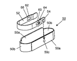
図5、図6及び図7を参照して、グリップベルト12の構造を説明する。グリップベルト12は、おおまかに、ベルト部50と、ベルト部50の外周に沿って配設したレール部材52とからなる。ベルト部50は、適切な硬度を有するパッド部50aと、バッド部50aの両端間を弾性的に接続して、手の平が入る空間又はリングを形成する接続部50bとからなる。パッド部50aは、グリップベルト12の使用時に使用者の手の平又は手の甲に当接する。接続部50bは伸縮可能であって、伸縮することで使用者の手の大きさに合うようにベルト周長が変化する。   The structure of the grip belt 12 will be described with reference to FIGS. The grip belt 12 roughly includes a belt portion 50 and a rail member 52 disposed along the outer periphery of the belt portion 50. The belt portion 50 includes a pad portion 50a having an appropriate hardness and a connection portion 50b that elastically connects between both ends of the pad portion 50a to form a space or ring in which a palm enters. The pad portion 50a comes into contact with the palm or back of the user when the grip belt 12 is used. The connecting portion 50b can be expanded and contracted, and the belt circumference changes so as to match the size of the user's hand by expanding and contracting.

レール部材52は、エラストマなどの可撓性材料を用いて成形したベルト状の部材であり、その両端がファスナ54,54によりベルト部50に接合する。ファスナ54はレール部材52に挿通した、太くなった頭部を有する突起である。ファスナ54をベルト部50の対応する孔50cに嵌合することで、ベルト部50にレール部材52が一体化される。   The rail member 52 is a belt-like member formed by using a flexible material such as an elastomer, and both ends thereof are joined to the belt portion 50 by fasteners 54 and 54. The fastener 54 is a protrusion having a thickened head inserted through the rail member 52. The rail member 52 is integrated with the belt portion 50 by fitting the fasteners 54 into the corresponding holes 50 c of the belt portion 50.

ベルト部50は、本体10の把持を補助する把持ベルトとして機能し、レール部材52が、特許請求の範囲の接続部材として機能する。   The belt portion 50 functions as a grip belt that assists in gripping the main body 10, and the rail member 52 functions as a connection member in the claims.

図8は、レール部材52を本体10に接続する途中の斜視図を示す。本体10の把持側面に設けたレール通し環56にレール部材52を挿通し、図5乃至図7を参照して説明したように、レール部材52をベルト部50と結合する。これにより、本体10にグリップベルト12が結合される。   FIG. 8 is a perspective view in the middle of connecting the rail member 52 to the main body 10. The rail member 52 is inserted into the rail through ring 56 provided on the grip side surface of the main body 10, and the rail member 52 is coupled to the belt portion 50 as described with reference to FIGS. 5 to 7. As a result, the grip belt 12 is coupled to the main body 10.

本体10は、レール部材52の長手方向に沿ってスライド移動が可能であり、従って、グリップベルト12のほぼ半分の長さにわたり、グリップベルト12に沿って周回するようにスライド移動可能となる。図9は、グリップベルト12を使って本体10を手の平側に把持する把持状態を示し、図10は、本体10を手の甲側に把持する把持状態を示す。本体10がグリップベルト12に沿ってその長手方向にスライド移動可能であるので、本体10は、図9に示す位置から図10に示す位置に、そしてその逆に、使用者の手58の周囲に移動可能である。   The main body 10 can be slid along the longitudinal direction of the rail member 52, and thus can be slid along the grip belt 12 over almost half the length of the grip belt 12. FIG. 9 shows a gripping state in which the main body 10 is gripped on the palm side using the grip belt 12, and FIG. 10 shows a gripping state in which the main body 10 is gripped on the back side of the hand. Since the main body 10 is slidable in the longitudinal direction along the grip belt 12, the main body 10 is moved from the position shown in FIG. 9 to the position shown in FIG. 10 and vice versa around the user's hand 58. It is movable.

図9に示す把持状態では、本体10が使用者の手58の手の平側にある。このとき、使用者は、指で上述の操作スイッチ類を操作できる。以降、この位置を使用位置と記す。図10に示す把持状態では、本体10が使用者の手58の手の甲側に退避した位置でグリップベルト12によって保持されている。このとき、使用者は手58の指を自由に動かせる状態となる。この状態は、本体10を携帯するのに適しており、以降、携帯位置と記す。携帯位置では、反転収納状態で本体10に収納されたLCDモニタ24の画面に再生画像を表示して鑑賞することが可能である。   In the gripping state shown in FIG. 9, the main body 10 is on the palm side of the user's hand 58. At this time, the user can operate the above-described operation switches with a finger. Hereinafter, this position is referred to as a use position. In the gripping state shown in FIG. 10, the main body 10 is held by the grip belt 12 at a position retracted to the back side of the user's hand 58. At this time, the user can move the finger of the hand 58 freely. This state is suitable for carrying the main body 10 and is hereinafter referred to as a carrying position. At the portable position, the playback image can be displayed on the screen of the LCD monitor 24 housed in the main body 10 in the inverted storage state for viewing.

グリップベルト12を使用者の手58に装着した状態においては、ベルト部50が使用者の手58の大きさに合わせて伸縮し、レール部材52はそれに倣って湾曲具合が変化する。レール部材52には、上述のように可撓性を持たせている。この可撓性により、レール部材52の湾曲具合が変化しても、その撓みを利用して、本体10はレール部材52に沿って移動可能である。   In a state in which the grip belt 12 is attached to the user's hand 58, the belt portion 50 expands and contracts according to the size of the user's hand 58, and the rail member 52 changes its bending state accordingly. The rail member 52 is flexible as described above. Even if the bending state of the rail member 52 changes due to this flexibility, the main body 10 can move along the rail member 52 using the bending.

レール部材52は、ベルト部50の伸縮に追従して湾曲具合が変化する柔軟性と、本体10を保持するのに適切な硬度とが両立するような、材質、厚み及び幅になっている。   The rail member 52 has a material, a thickness, and a width so that the flexibility that changes the bending state following the expansion and contraction of the belt portion 50 and the hardness that is appropriate for holding the main body 10 are compatible.

図11及び図12は、レール部材52と本体10との係合部分の構造を示す平面図である。図11(A)〜(D)は、本体10を使用位置に向けて移動していく様子を順に示す。図12(A),(B),(C)は、本体10を携帯位置に向けて移動していく様子を順に示す。但し、図11及び図12では、本体10のレール通し環56を断面で図示してある。   11 and 12 are plan views illustrating the structure of the engaging portion between the rail member 52 and the main body 10. FIGS. 11A to 11D sequentially show how the main body 10 is moved toward the use position. 12A, 12B, and 12C sequentially show how the main body 10 is moved toward the portable position. However, in FIG.11 and FIG.12, the rail penetration ring 56 of the main body 10 is shown in the cross section.

レール部材52は、本体10を使用位置に固定するためのクリック爪(又は突起)60と、携帯位置に固定するためのクリック爪(又は突起)62を側面に具備する。クリック爪60,62は、レール部材52の幅方向の両側に一対になって設けられ、レール通し環56に係合することで本体10をそれぞれ使用位置及び携帯位置に固定する。レール部材52には、クリック爪60,62がレール通し環56に押されて内側に変形するのを容易にする逃げ孔64,66を設けてある。   The rail member 52 includes a click claw (or protrusion) 60 for fixing the main body 10 in the use position and a click claw (or protrusion) 62 for fixing the main body 10 in the carrying position. The click claws 60 and 62 are provided as a pair on both sides of the rail member 52 in the width direction, and engage the rail through ring 56 to fix the main body 10 at the use position and the carrying position, respectively. The rail member 52 is provided with relief holes 64 and 66 that make it easy for the click claws 60 and 62 to be pushed by the rail through ring 56 and deformed inward.

図11(A)に示す位置から本体10を使用位置に向けて移動していくと、図11(B)に示すように、レール通し環56にクリック爪60が当接する。さらに、本体10を移動させると、図11(C)に示すように、クリック爪60がレール通し環56の内側に押し込まれる。続けて、本体10を移動させると、図11(D)に示すように、レール通し環56がクリック爪60を乗り越える。この状態では、クリック爪60は、その弾性力で初期位置に復帰し、レール通し環56の縁に係合する。レール部材52の先端部は、クランク部52aとして、図8に示すように、ベルト部50との接合部に向けてクランク状に折り曲げてある。このクランク部52aとクリック爪60によりレール通し環56が挟持され、その結果として、本体10が、この位置(使用位置)に保持される。   When the main body 10 is moved from the position shown in FIG. 11A toward the use position, the click claw 60 comes into contact with the rail threading ring 56 as shown in FIG. 11B. Further, when the main body 10 is moved, the click claw 60 is pushed into the rail passing ring 56 as shown in FIG. Subsequently, when the main body 10 is moved, the rail threading ring 56 gets over the click claw 60 as shown in FIG. In this state, the click claw 60 returns to the initial position by its elastic force and engages with the edge of the rail threading ring 56. As shown in FIG. 8, the distal end portion of the rail member 52 is bent in a crank shape toward the joint portion with the belt portion 50 as shown in FIG. 8. The rail passage ring 56 is clamped by the crank portion 52a and the click claw 60, and as a result, the main body 10 is held at this position (use position).

本体10を携帯位置に向けて移動する場合も同様である。即ち、図12(A)に示す位置から図12(B)に示す位置を経由して図12(C)に示す位置に、クリック爪62を変形させながら本体10が移動する。本体10は、最終的に、レール部材52の反対端のクランク部52aとクリック爪62によりレール通し環56が挟持され、その結果として、本体10はこの位置(携帯位置)に保持される。   The same applies to the case where the main body 10 is moved toward the portable position. That is, the main body 10 moves from the position shown in FIG. 12A to the position shown in FIG. 12C via the position shown in FIG. 12B while deforming the click claw 62. In the main body 10, the rail passing ring 56 is finally sandwiched between the crank portion 52a at the opposite end of the rail member 52 and the click claw 62, and as a result, the main body 10 is held in this position (portable position).

使用位置及び携帯位置から抜け出る場合には、上述の説明とは逆の経路又は手順を辿ることになる。   When exiting from the use position and the portable position, the route or procedure reverse to the above description is followed.

次に、本体10が使用位置にあることを検知する使用位置検知機構を説明する。図13は、本体10とグリップベルト12が分離された状態の斜視図を示す。図14は、使用位置近辺での本体10とグリップベルト12の関係を示す部分横断面図を示す。図13では、本体10の溝68及び検知スイッチ70を明記するために、レール通し環56を、一部切り欠いて図示してある。   Next, a use position detection mechanism that detects that the main body 10 is in the use position will be described. FIG. 13 is a perspective view showing a state where the main body 10 and the grip belt 12 are separated. FIG. 14 is a partial cross-sectional view showing the relationship between the main body 10 and the grip belt 12 in the vicinity of the use position. In FIG. 13, in order to clearly indicate the groove 68 and the detection switch 70 of the main body 10, the rail threading ring 56 is partially cut away.

レール部材52には、本体10方向に突起72を持った延出部74を、逃げ孔64に入り込むように設けてある。他方、本体10には、突起72に対応する溝68を形成し、溝68の一端に検知スイッチ70を配置してある。   The rail member 52 is provided with an extending portion 74 having a protrusion 72 in the direction of the main body 10 so as to enter the escape hole 64. On the other hand, a groove 68 corresponding to the protrusion 72 is formed in the main body 10, and a detection switch 70 is disposed at one end of the groove 68.

図14(A)は、本体10を使用位置に移動する初期の様子を示す。図14(A)に示す状態は、図11(A)に示す状態に対応しており、クリック爪60がレール通し環56に当接する以前の状態にある。突起72の頂点が本体10の側面に当接し、延出部74は厚み方向に撓んだ状態となっている。   FIG. 14A shows an initial state in which the main body 10 is moved to the use position. The state shown in FIG. 14 (A) corresponds to the state shown in FIG. 11 (A), and is in a state before the click claw 60 contacts the rail ring 56. The apex of the protrusion 72 is in contact with the side surface of the main body 10, and the extending portion 74 is bent in the thickness direction.

次に、図14(B)に示すように、本体10が使用位置に向けて移動すると、突起72が本体10の溝68に落ち込む。この状態は、図11(B)に示す状態に相当し、クリック爪60がレール通し環56に当接するタイミングにほぼ等しい。   Next, as shown in FIG. 14B, when the main body 10 moves toward the use position, the protrusion 72 falls into the groove 68 of the main body 10. This state corresponds to the state shown in FIG. 11B, and is almost equal to the timing at which the click pawl 60 contacts the rail passing ring 56.

さらに本体10を使用位置に向けて移動し、最終的に使用位置に到達するか、その直前で、図14(C)に示すように、突起72が本体10の検知スイッチ70を押圧する。検知スイッチ70の検知出力は、図4に示すように、制御部40に供給されている。制御部40は、検知スイッチ70の検知出力により、本体10が使用位置にセットされたかどうかを判別出来る。   Further, the main body 10 is moved toward the use position and finally reaches the use position, or just before that, the protrusion 72 presses the detection switch 70 of the main body 10 as shown in FIG. The detection output of the detection switch 70 is supplied to the control unit 40 as shown in FIG. The control unit 40 can determine whether or not the main body 10 is set at the use position based on the detection output of the detection switch 70.

使用位置から脱出する場合は、以上の手順の逆を辿る。クリック爪60がレール通し環56を乗り越えた後、突起72が溝68の終端に当接して持ち上がり、溝68を脱出する。   To escape from the use position, the reverse of the above procedure is followed. After the click claw 60 rides over the rail threading ring 56, the protrusion 72 comes into contact with the terminal end of the groove 68 and lifts up to escape the groove 68.

制御部40は、検知スイッチ70の検知出力に応じて、以下のように各部を制御する。図15は、その制御動作のフローチャートを示す。本実施例のビデオカメラは画像を撮影記録する撮影モードと、記録画像を再生する再生モードとを備え、使用者は、モード切替えボタン36の操作により動作モードを選択できる。また、電源スイッチ30がオフの場合でも、制御部40の最低限の機能は動作している。   The control unit 40 controls each unit as follows according to the detection output of the detection switch 70. FIG. 15 shows a flowchart of the control operation. The video camera of the present embodiment has a shooting mode for shooting and recording images and a playback mode for playing back recorded images, and the user can select an operation mode by operating the mode switching button 36. Even when the power switch 30 is off, the minimum functions of the control unit 40 are operating.

制御部40は、所定の時間間隔で検知スイッチ70の出力を監視し、本体10が使用位置かそれ以外の位置かを判別する(S1)。動作モードが撮影モードである場合、ステップS3に進み、再生モードの場合には、ステップS13に進む(S2)。   The control unit 40 monitors the output of the detection switch 70 at a predetermined time interval, and determines whether the main body 10 is in the use position or other position (S1). If the operation mode is the shooting mode, the process proceeds to step S3. If the operation mode is the reproduction mode, the process proceeds to step S13 (S2).

撮影モードで、本体10が使用位置にある場合(S3)で、電源がオフであれば(S4)、制御部40は、各スイッチの操作を受け付けと応答を準備する(S5)。電源スイッチ30の操作により、電源がオンになると、制御部40は、カメラユニット14から記録再生処理回路20までの全システムを起動する(S6)。そして、制御部40は、バリアを開けて撮影可能状態とし(S7)、撮影待機状態に移行する(S8)。使用者による電源スイッチ30の操作に拠らずとも、自動で電源をオンとし、これらの起動処理(S6,S7)を経て撮影待機状態に移行しても良い。電源が既にオンの場合(S4)、そのまま撮影待機状態を維持する(S8)。   When the main body 10 is in the use position in the shooting mode (S3) and the power is off (S4), the control unit 40 accepts the operation of each switch and prepares a response (S5). When the power is turned on by operating the power switch 30, the control unit 40 activates the entire system from the camera unit 14 to the recording / reproducing processing circuit 20 (S6). Then, the control unit 40 opens the barrier to make the photographing ready state (S7), and shifts to the photographing standby state (S8). Even if the user does not depend on the operation of the power switch 30, the power may be automatically turned on, and a transition to the photographing standby state may be made through these activation processes (S6, S7). If the power is already on (S4), the shooting standby state is maintained as it is (S8).

撮影モード(S2)で、本体10が使用位置以外の位置にある場合(S3)、電源がオンかどうかを調べる(S9)。電源がオンの場合(S9)、制御部40は、記録動作を終了するなど所定の終了処理を行い、バリアを閉じる(S10)。各操作スイッチへの応答を禁じて、操作無効状態とし(S11)、電源をオフとする(S12)。電源が既にオフであれば(S9)、そのまま、電源オフ状態を維持する(S12)。   When the main body 10 is in a position other than the use position in the shooting mode (S2) (S3), it is checked whether the power is on (S9). When the power is on (S9), the control unit 40 performs a predetermined termination process such as ending the recording operation and closes the barrier (S10). The response to each operation switch is prohibited, the operation is disabled (S11), and the power is turned off (S12). If the power is already off (S9), the power off state is maintained as it is (S12).

このように、本実施例では、本体10が使用位置以外に位置して、撮影モードにあるときには、電源をオフにするか(S9,S12)、又は、電源オン操作を受け付けないようにする(S11)。換言すれば、本体10が使用位置にないときには、撮影モードを禁止する(S10)。また、撮影モードであり、且つ、本体10が使用位置にあるときに限り、バリアを開く(S7)。   As described above, in this embodiment, when the main body 10 is located at a position other than the use position and is in the photographing mode, the power is turned off (S9, S12) or the power-on operation is not accepted (S9, S12). S11). In other words, when the main body 10 is not in the use position, the shooting mode is prohibited (S10). Further, the barrier is opened only when the photographing mode is set and the main body 10 is in the use position (S7).

次に再生モードの場合の制御動作を説明する。再生モードで(S2)、本体10が使用位置にあり(S13)、電源がオフの場合(S14)、制御部40は、電源スイッチ30のオン操作の受け付けを準備して待機する(S15)。電源スイッチ30のオン操作に応じて、制御部40は全体の電源をオンとし、記録再生処理回路20を起動する(S16)。カメラユニット14と信号処理回路16は、撮影時にのみ必要であるので、起動しない。このようにして、再生待機状態に移行する(S17)。既に電源がオンであれば(S14)、そのまま、再生待機状態を維持する(S17)。   Next, the control operation in the playback mode will be described. In the reproduction mode (S2), when the main body 10 is in the use position (S13) and the power is off (S14), the control unit 40 prepares to accept the on operation of the power switch 30 and waits (S15). In response to the ON operation of the power switch 30, the control unit 40 turns on the entire power supply and activates the recording / reproducing processing circuit 20 (S16). The camera unit 14 and the signal processing circuit 16 are not activated because they are required only during shooting. In this way, the reproduction standby state is entered (S17). If the power is already on (S14), the reproduction standby state is maintained as it is (S17).

再生モードで(S2)、本体10が使用位置にない場合(S13)、LCDモニタ24の姿勢又は位置を調べる(S18)。LCDモニタ24が反転収納状態にある場合(S18)、すなわち、表示画面を外側に向けて収納されている場合で、電源がオフかどうかを調べる(S19)。電源がオフの場合、制御部40は、電源スイッチ30のオン操作の受け付けを準備して待機する(S20)。電源スイッチ30のオン操作に応じて、制御部40は、全体の電源をオンとし、記録再生処理回路20を起動し(S21)、再生待機状態に移行する(S22)。既に電源がオンであれば(S19)、そのまま再生待機状態を維持する(S22)。   In the reproduction mode (S2), when the main body 10 is not in the use position (S13), the posture or position of the LCD monitor 24 is checked (S18). When the LCD monitor 24 is in the inverted storage state (S18), that is, when the display screen is stored with the display screen facing outward, it is checked whether the power is off (S19). When the power is off, the control unit 40 prepares to accept the ON operation of the power switch 30 and waits (S20). In response to the ON operation of the power switch 30, the control unit 40 turns on the entire power supply, activates the recording / reproduction processing circuit 20 (S21), and shifts to a reproduction standby state (S22). If the power is already on (S19), the reproduction standby state is maintained as it is (S22).

LCDモニタ24が反転収納状態以外の場合で(S18)、電源がオンであれば(S23)、制御部40は、終了処理を行って(S24)、電源をオフにする(S25)。電源がオフであれば(S23)、制御部40は、そのまま電源オフ状態を維持する(S25)。   If the LCD monitor 24 is in a state other than the inverted storage state (S18) and the power is on (S23), the control unit 40 performs a termination process (S24) and turns off the power (S25). If the power is off (S23), the control unit 40 maintains the power off state as it is (S25).

以上のように、再生モードでは、使用位置以外でも、LCDモニタ24が反転収納状態であれば、電源オンを許可し、電源スイッチ30のオン操作を受け付ける。再生モードでは、カメラユニット14を始め撮影モードにのみ関与するブロックは停止状態、即ち、起動していない状態、又は電力を消費しない状態に維持される。バリアは閉じたままとし、画像再生操作に使用しないスイッチは無効とする。   As described above, in the playback mode, if the LCD monitor 24 is in the reverse storage state even at a position other than the use position, the power-on is permitted and the power switch 30 is turned on. In the playback mode, the blocks related only to the shooting mode including the camera unit 14 are maintained in a stopped state, that is, in a state where they are not activated or in a state where no power is consumed. The barrier remains closed, and switches that are not used for image playback operations are disabled.

本体10が使用位置にあるかどうか、及びLCDモニタ24の位置の判別は、所定の時間間隔で繰り返される。本体10及びLCDモニタ24の位置の変更に応じて、制御部40は、上述のフローに従い、適切に電源状態やスイッチ操作に対する応答を制御する。   The determination of whether the main body 10 is in the use position and the position of the LCD monitor 24 is repeated at predetermined time intervals. In accordance with the change of the positions of the main body 10 and the LCD monitor 24, the control unit 40 appropriately controls the power supply state and the response to the switch operation according to the above-described flow.

本体10が使用位置にあるときと、それ以外の位置にあるときとで、各スイッチの操作を受け付ける応答時間を異ならせても良い。例えば、使用位置以外では、電源スイッチ30の操作応答時間を長くすることによって、不用意に電源スイッチ30が押圧されて起動してしまうリスクを低減できる。   The response time for accepting the operation of each switch may be different depending on whether the main body 10 is in the use position or in any other position. For example, by increasing the operation response time of the power switch 30 outside the use position, the risk that the power switch 30 is inadvertently pressed and started can be reduced.

図16は、本実施例のビデオカメラを使用位置で把持し、LCDモニタ24を収納状態で本体10に収納したときの斜視図を示す。図17は、本実施例のビデオカメラを使用位置で把持し、LCDモニタ24をその画面を背面方向に向けて開いた状態にしたときの斜視図を示す。図18は、本実施例のビデオカメラを使用位置で把持しつつ、LCDモニタ24を反転収納状態に置いたときの斜視図を示す。図19は、本実施例のビデオカメラを手の甲側の携帯位置に置き、LCDモニタ24を反転収納状態に置いたときの斜視図を示す。   FIG. 16 is a perspective view when the video camera of the present embodiment is gripped at the use position and the LCD monitor 24 is stored in the main body 10 in the storage state. FIG. 17 shows a perspective view when the video camera of the present embodiment is gripped at the use position and the LCD monitor 24 is opened with its screen facing in the back direction. FIG. 18 is a perspective view when the LCD monitor 24 is placed in the inverted storage state while holding the video camera of the present embodiment at the use position. FIG. 19 is a perspective view when the video camera of the present embodiment is placed in the portable position on the back side of the hand and the LCD monitor 24 is placed in the inverted storage state.

このように、本実施例では、使用位置と携帯位置との間で把持位置を容易に移行できる。更には、使用位置にあるときには、現在状態に応じた適切な制御が選択実行されるので、利便性が向上する。   Thus, in the present embodiment, the gripping position can be easily shifted between the use position and the portable position. Furthermore, when in the use position, appropriate control according to the current state is selected and executed, so convenience is improved.

本発明の第2実施例を説明する。   A second embodiment of the present invention will be described.

図20は、第2実施例の外観斜視図を示す。本実施例のビデオカメラの本体110の側面に、グリップベルト112が装着される。図21は、グリップベルト112の斜視図を示す。図22は、本体110の、グリップベルト112を取り付ける側面を見る斜視図を示す。   FIG. 20 shows an external perspective view of the second embodiment. A grip belt 112 is attached to the side surface of the main body 110 of the video camera of this embodiment. FIG. 21 shows a perspective view of the grip belt 112. FIG. 22 is a perspective view of the side surface of the main body 110 to which the grip belt 112 is attached.

グリップベルト112は、使用者の手の平から甲にかけて当接する略U字形状のパッド部114と、パッド部114のU字の両端を弾性的に接続する接続部116とから成る。接続部116の伸縮性によって、グリップベルト112の周長が可変である。   The grip belt 112 includes a substantially U-shaped pad portion 114 that abuts from the palm of the user's palm to the back and a connection portion 116 that elastically connects both ends of the U-shape of the pad portion 114. The circumference of the grip belt 112 is variable depending on the stretchability of the connecting portion 116.

本体110の側面には、図22に示すように、略L字形状のアーム部材118を取り付けてある。アーム部材118は、エラストマなどの可撓性材料を用いて成形した部材からなり、一端が本体110に固定され、他端は、パッド部114に軸120を用いて回動可能に接続される。   A substantially L-shaped arm member 118 is attached to the side surface of the main body 110 as shown in FIG. The arm member 118 is formed of a member formed using a flexible material such as an elastomer, and one end is fixed to the main body 110 and the other end is rotatably connected to the pad portion 114 using the shaft 120.

図23は、本体110を手の平側の使用位置から手の甲側の携帯位置に移動させる途中の状態を示す。図24は、本体110が手の甲側の携帯位置に移動完了した状態を示す。使用位置とは、第1実施例と同様に、本体110が使用者の手の平側にある位置である。その位置から、アーム部材118の可撓性を利用して本体110を手の平から離間させ、その状態を保ちながら軸120を中心に手の甲側に本体110を回動する。途中、指先を曲げてくぐらせるなどして、本体110を手の甲側に回しこむ。最終的に、図24に示すように、本体110が手の甲の位置に退避し、使用者の指が自由に動かせるようになる。   FIG. 23 shows a state in the middle of moving the main body 110 from the use position on the palm side to the portable position on the back side of the hand. FIG. 24 shows a state where the main body 110 has been moved to the portable position on the back side of the hand. The use position is a position where the main body 110 is on the palm side of the user as in the first embodiment. From this position, the main body 110 is separated from the palm of the hand using the flexibility of the arm member 118, and the main body 110 is rotated toward the back of the hand around the shaft 120 while maintaining this state. In the middle, the main body 110 is turned toward the back of the hand by bending the fingertip. Finally, as shown in FIG. 24, the main body 110 is retracted to the position of the back of the hand, and the user's finger can move freely.

本実施例では、軸120の周辺に、使用位置を検知する手段を組み込んである。図25は、本体110が使用位置(手の平側)にあるときの背面図を示し、図26は、本体110が携帯位置(手の甲側)にあるときの背面図を示す。軸120はパッド部114に固定されている。アーム部118は、軸120を中心に回動する。アーム部118に、使用位置にあることを検知する検知スイッチ122を配置してある。検知スイッチ122は、アーム部118の回動と共に、軸120に形成したカム部124の周囲を移動し、所定位相でカム部124に押圧され、オン/オフが切り替わるようになっている。   In the present embodiment, a means for detecting the use position is incorporated around the shaft 120. FIG. 25 shows a rear view when the main body 110 is in the use position (the palm side), and FIG. 26 shows a rear view when the main body 110 is in the portable position (the back side of the hand). The shaft 120 is fixed to the pad portion 114. The arm portion 118 rotates about the shaft 120. A detection switch 122 that detects that the arm portion 118 is in the use position is disposed. The detection switch 122 moves around the cam portion 124 formed on the shaft 120 as the arm portion 118 rotates, and is pressed by the cam portion 124 at a predetermined phase to be switched on / off.

例えば、検知スイッチ122は、図25に示す使用位置ではオフになり、図26に示す位置ではオンになる。図25に示す状態以外の位相では、検知スイッチ122のノブがカム部124により押圧され、検知スイッチ122は、オンである。同様に、図26に示す状態(携帯位置)では、検知スイッチ122のノブはカム部124によって押圧され、検知スイッチ122はオンとなる。   For example, the detection switch 122 is turned off at the use position shown in FIG. 25 and turned on at the position shown in FIG. In a phase other than the state shown in FIG. 25, the knob of the detection switch 122 is pressed by the cam portion 124, and the detection switch 122 is on. Similarly, in the state shown in FIG. 26 (portable position), the knob of the detection switch 122 is pressed by the cam portion 124, and the detection switch 122 is turned on.

検知スイッチ122の出力は、図示しないリード線で本体110内の制御部に供給される。当該制御部は、制御部40と同様に、検知スイッチ122の検知出力に応じて、本体110の各部を制御する。   The output of the detection switch 122 is supplied to the control unit in the main body 110 through a lead wire (not shown). Similar to the control unit 40, the control unit controls each unit of the main body 110 according to the detection output of the detection switch 122.

電源状態の制御、バリアの駆動及びスイッチ応答制限については、第1実施例と同じであるので、詳細な説明を省略する。   Since the control of the power supply state, the driving of the barrier, and the switch response limitation are the same as in the first embodiment, detailed description thereof is omitted.

第1実施例との相違として、本実施例では、使用者に対するビデオカメラ110の天地方向が、使用位置と携帯位置とで変化する。図27は、使用者の手の平側に本体110を位置させたときの様子を示し、図28は、手の甲側に本体110を位置させたときの様子を示す。何れも、LCDモニタは、反転収納状態にあるので、携帯位置でも再生モードの起動が許可される。このとき、同じ反転収納状態であっても、使用者に対してLCDモニタの画面の天地が逆となる。そこで、この実施例では、使用位置での再生画像に対して、携帯位置でのそれを上下反転表示することで正立像とする。   As a difference from the first embodiment, in this embodiment, the vertical direction of the video camera 110 with respect to the user changes between the use position and the portable position. 27 shows a state when the main body 110 is positioned on the palm side of the user, and FIG. 28 shows a state when the main body 110 is positioned on the back side of the user. In any case, since the LCD monitor is in the inverted storage state, the playback mode is allowed to be activated even in the portable position. At this time, the top and bottom of the LCD monitor screen is reversed for the user even in the same inverted storage state. Therefore, in this embodiment, an upright image is obtained by displaying the reproduced image at the use position upside down with respect to the reproduced image at the use position.

このように、本体110の位置を判別し、表示の内容を制御することで、使用者の利便性を向上できる。   Thus, the convenience of the user can be improved by determining the position of the main body 110 and controlling the content of the display.

本発明の一実施例であるビデオカメラの斜め正面から見た外観斜視図を示す。The external appearance perspective view seen from the diagonal front of the video camera which is one Example of this invention is shown. 別の方向から見た本実施例の外観斜視図を示す。The external appearance perspective view of the present Example seen from another direction is shown. 本体10のみを背面方向から見た外観斜視図を示す。The external appearance perspective view which looked at only the main body 10 from the back direction is shown. 本体10に収容される回路部品の機能ブロック図を示す。2 is a functional block diagram of circuit components housed in the main body 10. FIG. 組み立て状態のグリップベルト12の斜視図を示す。The perspective view of the grip belt 12 of an assembly state is shown. グリップベルト12の分解斜視図を示す。The disassembled perspective view of the grip belt 12 is shown. 別の方向から見たグリップベルト12の分解斜視図を示す。The disassembled perspective view of the grip belt 12 seen from another direction is shown. レール部材52を本体10に接続する途中の斜視図を示す。The perspective view in the middle of connecting the rail member 52 to the main body 10 is shown. グリップベルト12を使って本体10を手の平側に把持する把持状態を示す。A gripping state in which the main body 10 is gripped to the palm side using the grip belt 12 is shown. 本体10を手の甲側に把持する把持状態を示す。A gripping state in which the main body 10 is gripped on the back side of the hand is shown. レール部材52と本体10との係合部分の構造を示す平面図で、本体10を使用位置に向けて移動していく様子を順に示す。It is a top view which shows the structure of the engaging part of the rail member 52 and the main body 10, and a mode that the main body 10 is moved toward a use position is shown in order. レール部材52と本体10との係合部分の構造を示す平面図で、本体10を携帯位置に向けて移動していく様子を順に示す。It is a top view which shows the structure of the engaging part of the rail member 52 and the main body 10, and a mode that the main body 10 is moved toward a carrying position is shown in order. 本体10とグリップベルト12が分離された状態の斜視図を示す。A perspective view in the state where main part 10 and grip belt 12 were separated is shown. 使用位置近辺での本体10とグリップベルト12の関係を示す部分横断面図を示す。The partial cross-sectional view which shows the relationship between the main body 10 and the grip belt 12 in the use position vicinity is shown. 制御部40の制御動作のフローチャートを示す。The flowchart of the control action of the control part 40 is shown. 本実施例のビデオカメラを使用位置で把持し、LCDモニタ24を収納状態で本体10に収納したときの斜視図を示す。FIG. 2 is a perspective view when the video camera of the present embodiment is gripped at a use position and the LCD monitor 24 is stored in the main body 10 in the storage state. 本実施例のビデオカメラを使用位置で把持し、LCDモニタ24をその画面を背面方向に向けて開いた状態にしたときの斜視図を示す。The perspective view when the video camera of a present Example is hold | gripped in a use position and the LCD monitor 24 was made into the state opened toward the back direction is shown. 本実施例のビデオカメラを使用位置で把持しつつ、LCDモニタ24を反転収納状態に置いたときの斜視図を示す。FIG. 2 is a perspective view when the LCD monitor 24 is placed in the inverted storage state while holding the video camera of the present embodiment at the use position. 本実施例のビデオカメラを手の甲側の携帯位置に置き、LCDモニタ24を反転収納状態に置いたときの斜視図を示す。The perspective view when the video camera of the present embodiment is placed at the portable position on the back side of the hand and the LCD monitor 24 is placed in the inverted storage state is shown. 第2実施例の外観斜視図を示す。The external appearance perspective view of 2nd Example is shown. グリップベルト112の斜視図を示す。The perspective view of the grip belt 112 is shown. 本体110の、グリップベルト112を取り付ける側面を見る斜視図を示す。The perspective view which looks at the side surface which attaches the grip belt 112 of the main body 110 is shown. 本体110を手の平側の使用位置から手の甲側の携帯位置に移動させる途中の状態を示す。The state in the middle of moving the main body 110 from the use position on the palm side to the portable position on the back side of the hand is shown. 本体110が手の甲側の携帯位置に移動完了した状態を示す。A state in which the main body 110 has been moved to the portable position on the back side of the hand is shown. 本体110が使用位置(手の平側)にあるときの背面図を示す。The rear view when the main body 110 exists in a use position (palm side) is shown. 本体110が携帯位置(手の甲側)にあるときの背面図を示す。The rear view when the main body 110 exists in a carrying position (back side of a hand) is shown. 使用者の手の平側に本体110を位置させたときの様子を示す。A state when the main body 110 is positioned on the palm side of the user's palm is shown. 使用者の手の甲側に本体110を位置させたときの様子を示す。A state when the main body 110 is positioned on the back side of the user's hand is shown. 従来のビデオカメラ210の外観斜視図を示す。An external perspective view of a conventional video camera 210 is shown. 別の方角から見たビデオカメラ210の外観斜視図を示す。The external appearance perspective view of the video camera 210 seen from another direction is shown. グリップベルト216の補助下に撮影者がビデオカメラ210を把持している状態を示す。A state in which the photographer is holding the video camera 210 with the assistance of the grip belt 216 is shown. 肩掛けベルト224を装着した従来のビデオカメラの斜視図である。It is a perspective view of the conventional video camera with which the shoulder belt 224 was mounted | worn.

符号の説明Explanation of symbols

10:本体
12:グリップベルト
14:カメラユニット
16:信号処理回路
18:マイク
20:記録再生処理回路
22:記録メモリ
24:LCDモニタ
26:キャラクタジェネレータ
28:スピーカ
30:電源スイッチ
32:トリガースイッチ
34:ズームレバー
36:モード切替えボタン
38:設定ボタン
40:制御部
42:ヒンジ機構
44:開閉検知スイッチ
46:回転検知スイッチ
47:バッテリパック
48:電動バリア機構
48a:バリア開閉検知スイッチ
48b:バリア駆動モータ
50:ベルト部
50a:パッド部
50b:接続部
50c:孔
52:レール部材
52a:クランク部
54:ファスナ
56:レール通し環
58:使用者の手
60,62:クリック爪
64,66:逃げ孔
68:溝
70:検知スイッチ
72:突起
74:延出部
110:本体
112:グリップベルト
114:パッド部
116:接続部
118:アーム部材
120:軸
122:検知スイッチ
124:カム部
210:ビデオカメラ
212:把持部
214:電源スイッチ
216:グリップベルト
218:固定部
220:通し環
222:甲当て部
224:肩掛けベルト
10: Body 12: Grip belt 14: Camera unit 16: Signal processing circuit 18: Microphone 20: Recording / reproduction processing circuit 22: Recording memory 24: LCD monitor 26: Character generator 28: Speaker 30: Power switch 32: Trigger switch 34: Zoom lever 36: Mode switching button 38: Setting button 40: Control unit 42: Hinge mechanism 44: Open / close detection switch 46: Rotation detection switch 47: Battery pack 48: Electric barrier mechanism 48a: Barrier open / close detection switch 48b: Barrier drive motor 50 : Belt part 50a: Pad part 50b: Connection part 50c: Hole 52: Rail member 52a: Crank part 54: Fastener 56: Rail threading ring 58: User's hand 60, 62: Click claw 64, 66: Relief hole 68: Groove 70: Detection switch 72: Protrusion 74: Extension part 10: body 112: grip belt 114: pad portion 116: connection portion 118: arm member 120: shaft 122: detection switch 124: cam portion 210: video camera 212: gripping portion 214: power switch 216: grip belt 218: fixing portion 220: threading ring 222: upper part 224: shoulder belt

Claims (6)

本体の把持を補助する把持ベルトと、
前記把持ベルトを前記本体に接続する接続部材であって、前記本体を使用者の手の平側と手の甲側の間でスライド及び回動の何れかにより移動可能な接続部材
とを具備することを特徴とする電子機器。
A gripping belt that assists in gripping the body;
A connecting member for connecting the grip belt to the main body, the connecting member being movable between the palm side and the back side of the user by either sliding or rotating ; Electronic equipment.
更に、
前記接続部材に対する前記本体の位置を判別する判別手段と、
前記判別手段の出力に応じて前記本体の動作を制御する制御手段
とを具備することを特徴とする請求項1に記載の電子機器。
Furthermore,
Discriminating means for discriminating the position of the main body with respect to the connection member;
The electronic apparatus according to claim 1, further comprising a control unit that controls an operation of the main body according to an output of the determination unit.
前記制御手段は、前記判別手段の出力に応じて、前記本体の電源状態を制御することを特徴とする請求項2に記載の電子機器。   The electronic device according to claim 2, wherein the control unit controls a power state of the main body according to an output of the determination unit. 前記制御手段は、前記判別手段の出力に応じて、前記本体の動作モードを制御することを特徴とする請求項2又は3に記載の電子機器。   The electronic apparatus according to claim 2, wherein the control unit controls an operation mode of the main body according to an output of the determination unit. 前記制御手段は、前記判別手段の出力に応じて、前記本体の機能の一部を制限することを特徴とする請求項2乃至4の何れか1項に記載の電子機器。   5. The electronic apparatus according to claim 2, wherein the control unit limits a part of the function of the main body according to an output of the determination unit. 更に表示手段を具備し、
前記制御手段は、前記判別手段の出力に応じ、前記表示手段で表示される内容を制御する
ことを特徴とする請求項2乃至5の何れか1項に記載の電子機器。
Furthermore, a display means is provided,
The electronic device according to claim 2, wherein the control unit controls contents displayed on the display unit in accordance with an output of the determination unit.
JP2007328182A 2007-12-20 2007-12-20 Electronics Expired - Fee Related JP4942203B2 (en)

Priority Applications (1)

Application Number Priority Date Filing Date Title
JP2007328182A JP4942203B2 (en) 2007-12-20 2007-12-20 Electronics

Applications Claiming Priority (1)

Application Number Priority Date Filing Date Title
JP2007328182A JP4942203B2 (en) 2007-12-20 2007-12-20 Electronics

Publications (3)

Publication Number Publication Date
JP2009152337A JP2009152337A (en) 2009-07-09
JP2009152337A5 JP2009152337A5 (en) 2011-02-10
JP4942203B2 true JP4942203B2 (en) 2012-05-30

Family

ID=40921155

Family Applications (1)

Application Number Title Priority Date Filing Date
JP2007328182A Expired - Fee Related JP4942203B2 (en) 2007-12-20 2007-12-20 Electronics

Country Status (1)

Country Link
JP (1) JP4942203B2 (en)

Families Citing this family (1)

* Cited by examiner, † Cited by third party
Publication number Priority date Publication date Assignee Title
WO2017149888A1 (en) 2016-03-04 2017-09-08 株式会社ソニー・インタラクティブエンタテインメント Operation apparatus

Family Cites Families (4)

* Cited by examiner, † Cited by third party
Publication number Priority date Publication date Assignee Title
JPH0370005U (en) * 1989-11-06 1991-07-12
JPH10178573A (en) * 1996-12-17 1998-06-30 Canon Inc Video camera
CA2323899A1 (en) * 1998-03-16 1999-09-23 Scott Pedersen Key palette improvements
IT1319615B1 (en) * 2000-02-18 2003-10-20 Caldana Franco DEVICE FOR THE QUICK AND EASY USE OF A SMALL MOBILE PHONE.

Also Published As

Publication number Publication date
JP2009152337A (en) 2009-07-09

Similar Documents

Publication Publication Date Title
JP3496207B2 (en) Video camera
US8104900B2 (en) Electronic device incorporating projector device
JP4607818B2 (en) camera
JP4713845B2 (en) Image display device
WO2005071947A1 (en) Turning hinge mechanism and image pick up device
JP4488088B2 (en) Still camera
JP2005210677A (en) Imaging device
JP2008085865A (en) Mobile device
JP2007258198A (en) Support structure of lid member and electronic equipment
JP2006287288A (en) Camera with image storage device
JP4942203B2 (en) Electronics
JP4151272B2 (en) Electronic device, hinge device, and imaging device
JP2006138958A (en) Camera and device for turning display device of camera
JP2011228939A (en) Recording and reproducing device
JP2000165719A (en) Image pickup device
JP2006138959A (en) Camera and mechanism to be supported
JP4569648B2 (en) Electronic device, hinge device, and imaging device
JP4184166B2 (en) Audio recording / playback device
JPH1139853A (en) Turning and interconnecting mechanism for apparatus cabinet, picture recording apparatus and picture recording/reproducing apparatus and picture recording/ reproducing apparatus with turnable cameras
JP2009300558A (en) Imaging apparatus
JP4219233B2 (en) Imaging device
JP2009177273A (en) Imaging apparatus
JP2766626B2 (en) Camera-integrated recording device with monitor
JP2766625B2 (en) Camera-integrated recording device with monitor
JP2000152053A (en) Grip structure

Legal Events

Date Code Title Description
A521 Request for written amendment filed

Free format text: JAPANESE INTERMEDIATE CODE: A523

Effective date: 20101217

A621 Written request for application examination

Free format text: JAPANESE INTERMEDIATE CODE: A621

Effective date: 20101217

A977 Report on retrieval

Free format text: JAPANESE INTERMEDIATE CODE: A971007

Effective date: 20120127

TRDD Decision of grant or rejection written
A01 Written decision to grant a patent or to grant a registration (utility model)

Free format text: JAPANESE INTERMEDIATE CODE: A01

Effective date: 20120131

A01 Written decision to grant a patent or to grant a registration (utility model)

Free format text: JAPANESE INTERMEDIATE CODE: A01

A61 First payment of annual fees (during grant procedure)

Free format text: JAPANESE INTERMEDIATE CODE: A61

Effective date: 20120227

R151 Written notification of patent or utility model registration

Ref document number: 4942203

Country of ref document: JP

Free format text: JAPANESE INTERMEDIATE CODE: R151

FPAY Renewal fee payment (event date is renewal date of database)

Free format text: PAYMENT UNTIL: 20150309

Year of fee payment: 3

RD03 Notification of appointment of power of attorney

Free format text: JAPANESE INTERMEDIATE CODE: R3D03

LAPS Cancellation because of no payment of annual fees