JP4939888B2 - Wireless communication device - Google Patents
Wireless communication device Download PDFInfo
- Publication number
- JP4939888B2 JP4939888B2 JP2006269287A JP2006269287A JP4939888B2 JP 4939888 B2 JP4939888 B2 JP 4939888B2 JP 2006269287 A JP2006269287 A JP 2006269287A JP 2006269287 A JP2006269287 A JP 2006269287A JP 4939888 B2 JP4939888 B2 JP 4939888B2
- Authority
- JP
- Japan
- Prior art keywords
- interference
- signal
- wireless communication
- weight
- wave
- Prior art date
- Legal status (The legal status is an assumption and is not a legal conclusion. Google has not performed a legal analysis and makes no representation as to the accuracy of the status listed.)
- Expired - Fee Related
Links
Images


Classifications
-
- H—ELECTRICITY
- H04—ELECTRIC COMMUNICATION TECHNIQUE
- H04B—TRANSMISSION
- H04B7/00—Radio transmission systems, i.e. using radiation field
- H04B7/02—Diversity systems; Multi-antenna system, i.e. transmission or reception using multiple antennas
- H04B7/04—Diversity systems; Multi-antenna system, i.e. transmission or reception using multiple antennas using two or more spaced independent antennas
- H04B7/0413—MIMO systems
- H04B7/0452—Multi-user MIMO systems
-
- H—ELECTRICITY
- H04—ELECTRIC COMMUNICATION TECHNIQUE
- H04B—TRANSMISSION
- H04B7/00—Radio transmission systems, i.e. using radiation field
- H04B7/02—Diversity systems; Multi-antenna system, i.e. transmission or reception using multiple antennas
- H04B7/04—Diversity systems; Multi-antenna system, i.e. transmission or reception using multiple antennas using two or more spaced independent antennas
- H04B7/08—Diversity systems; Multi-antenna system, i.e. transmission or reception using multiple antennas using two or more spaced independent antennas at the receiving station
- H04B7/0837—Diversity systems; Multi-antenna system, i.e. transmission or reception using multiple antennas using two or more spaced independent antennas at the receiving station using pre-detection combining
- H04B7/0842—Weighted combining
- H04B7/0848—Joint weighting
- H04B7/0857—Joint weighting using maximum ratio combining techniques, e.g. signal-to- interference ratio [SIR], received signal strenght indication [RSS]
-
- H—ELECTRICITY
- H04—ELECTRIC COMMUNICATION TECHNIQUE
- H04J—MULTIPLEX COMMUNICATION
- H04J99/00—Subject matter not provided for in other groups of this subclass
Landscapes
- Engineering & Computer Science (AREA)
- Computer Networks & Wireless Communication (AREA)
- Signal Processing (AREA)
- Noise Elimination (AREA)
- Mobile Radio Communication Systems (AREA)
- Radio Transmission System (AREA)
Description
本発明は、例えば複数の端末で同一チャネルを使用するマルチセル構成の無線通信システムの端末等に用いられ、干渉波源からの干渉成分を抑制して所望信号を受信可能な無線通信装置に関する。 The present invention relates to a wireless communication apparatus that can be used in, for example, a terminal of a wireless communication system having a multi-cell configuration in which a plurality of terminals use the same channel and receive a desired signal while suppressing an interference component from an interference wave source.
近年、無線通信の大容量化、高速化の要求が非常な高まりをみせており、有限な周波数資源の有効利用効率を更に向上させる方法の研究が盛んになっている。その一つの方法として、空間領域を利用する手法が注目を集めている。空間領域利用技術の一つは、アダプティブアレーアンテナ(適応アンテナ)であり、受信信号に乗算する重み付け係数(以下、この重み付け係数を「重み」という)により振幅と位相を調整することにより、所望方向から到来する所望信号を強く受信し、マルチパス干渉や同一チャネル干渉といった干渉成分信号を抑圧することができる。このような干渉抑圧効果により、通信システムの通信容量を改善することが可能となる。 In recent years, there has been a great increase in demand for higher capacity and higher speed of wireless communication, and research on methods for further improving the effective utilization efficiency of finite frequency resources has been actively conducted. As one of the methods, a technique using a spatial domain is attracting attention. One of the spatial domain utilization techniques is an adaptive array antenna (adaptive antenna), which adjusts the amplitude and phase by a weighting coefficient (hereinafter, this weighting coefficient is referred to as “weight”) to be multiplied with a received signal, thereby obtaining a desired direction. It is possible to strongly receive a desired signal arriving from and to suppress interference component signals such as multipath interference and co-channel interference. Such an interference suppression effect makes it possible to improve the communication capacity of the communication system.
また、空間領域を利用した別な技術として、伝搬路における空間的な直交性を利用することで、同一時刻、同一周波数、同一符号の物理チャネルを用いて異なるデータ系列を、同一の端末装置に対して伝送する空間多重(Space Division Multiplexing)(以下、SDMと記載)技術がある。SDM技術は、例えば非特許文献1において情報開示されており、送信機及び受信機共に複数のアンテナ素子を備え、アンテナ間での受信信号の相関性が低い伝搬環境下においてSDM伝送が実現できる。この場合、送信機の備える複数のアンテナから、アンテナ素子毎に同一時刻、同一周波数、同一符号の物理チャネルを用いて異なるデータ系列を送信し、受信機においては受信機の備える複数アンテナでの受信信号を、伝送路特性の推定値を基に分離受信する。これにより、空間多重チャネルを複数用いることで多値変調を用いずに高速化の達成が可能である。SDM伝送を行う場合、十分なS/N(信号対雑音比)条件下での送受信機間に多数の散乱体が存在する環境下では、送信機と受信機が同数のアンテナを備える場合、アンテナ数に比例した通信容量の拡大が可能となる。
In addition, as another technique using the spatial domain, by using spatial orthogonality in the propagation path, different data sequences can be transferred to the same terminal device using physical channels of the same time, the same frequency, and the same code. On the other hand, there is a technology of space division multiplexing (hereinafter referred to as SDM) for transmission. The SDM technology is disclosed in, for example, Non-Patent
上述したアダプティブアレーアンテナ技術及びSDM技術における干渉抑圧は、複数のアンテナ素子で受信された信号に対し、アンテナウエイトを乗算した後に加算合成する空間的なフィルタリング処理が用いられる。例えばSIR(信号電力対干渉雑音電力比)を最大化するMMSE(誤差最小二乗規範)アルゴリズム等によって動作する。しかしながら、このような干渉抑圧手法の前提条件として、干渉信号が所望信号とともに定常的に存在することを仮定している。そのため、特に、無線LAN等のパケット伝送を用いる無線通信システムでは、自セル、他セルからの干渉信号がバースト的に生成消滅することになり、上記前提条件を満たさない場合がある。すなわち、上記のような空間フィルタリング処理のアルゴリズムの適用後に、干渉信号に変動がある場合は、干渉抑圧を効果的に行えないという課題を有する。 The interference suppression in the above-described adaptive array antenna technique and SDM technique uses a spatial filtering process in which signals received by a plurality of antenna elements are multiplied and combined by antenna weights. For example, it operates according to an MMSE (Error Least Squares) algorithm that maximizes SIR (signal power to interference noise power ratio). However, as a precondition for such an interference suppression technique, it is assumed that the interference signal is constantly present along with the desired signal. Therefore, particularly in a wireless communication system using packet transmission such as a wireless LAN, interference signals from the own cell and other cells are generated and extinguished in bursts, and the above preconditions may not be satisfied. That is, there is a problem that interference suppression cannot be effectively performed when there is a variation in the interference signal after application of the above-described spatial filtering processing algorithm.
本発明は、上記事情に鑑みてなされたもので、干渉波が定常的に存在しない状態においても、非定常に現れる干渉波に適応した空間的フィルタリングを実現でき、干渉除去能力を高めることが可能な無線通信装置を提供することを目的とする。 The present invention has been made in view of the above circumstances, and can realize spatial filtering adapted to an interference wave that appears non-stationarily even in a state where the interference wave does not exist steadily, and can improve interference removal capability. An object of the present invention is to provide a wireless communication device.
本発明の無線通信装置は、干渉波成分の信号を選択的に受信する干渉波受信アンテナウエイトを用いて、前記干渉波成分を含む干渉信号を受信する干渉信号受信手段と、前記干渉信号受信手段の出力から、干渉波成分の信号レベルを検出する干渉波レベル検出手段と、前記干渉波レベル検出手段の出力を基に、所望信号を受信する所望波分離受信アンテナウエイトを可変する信号分離手段と、を有するものである。
この構成により、干渉波成分の信号レベルを基に所望波分離受信アンテナウエイトを可変することで、干渉波が定常的に存在しない状態においても、非定常に現れる干渉波に適応した空間的フィルタリングを実現でき、干渉除去能力を高めることが可能となる。
The wireless communication apparatus according to the present invention includes an interference signal receiving unit that receives an interference signal including the interference wave component using an interference wave receiving antenna weight that selectively receives a signal of the interference wave component, and the interference signal receiving unit. Interference wave level detection means for detecting the signal level of the interference wave component from the output of the signal, and signal separation means for varying the desired wave separation receiving antenna weight for receiving the desired signal based on the output of the interference wave level detection means, , Has.
With this configuration, by changing the desired wave separation receiving antenna weight based on the signal level of the interference wave component, spatial filtering adapted to the interference wave that appears unsteady even when the interference wave does not exist steadily This can be realized and the interference removal capability can be increased.
また、本発明は、上記の無線通信装置であって、前記所望波分離受信アンテナウエイトは、干渉波受信電力を最小化するウエイトであるものとする。 Also, the present invention is the above wireless communication apparatus, wherein the desired wave separation receiving antenna weight is a weight that minimizes interference wave reception power.
また、本発明は、上記の無線通信装置であって、前記所望波分離受信アンテナウエイトは、信号電力対干渉雑音電力を最大化するウエイトであるものとする。 Also, the present invention is the above wireless communication apparatus, wherein the desired wave separation receiving antenna weight is a weight that maximizes signal power versus interference noise power.
また、本発明は、上記の無線通信装置であって、前記所望波分離受信アンテナウエイトは、複数アンテナN個の内、Nより小さいk個からなるサブアレーに対して、干渉波受信電力を最小化するウエイトであるものとする。 Further, the present invention is the above wireless communication apparatus, wherein the desired wave separation receiving antenna weight minimizes interference wave reception power with respect to a sub-array comprising k antennas smaller than N among N antennas. It is assumed that the weight is
また、本発明は、上記の無線通信装置であって、前記信号分離手段は、他局干渉信号を優先的に除去するウエイトを乗算する第1のウエイト乗算部と、前記第1のウエイト乗算部の出力に対し、空間多重ストリームを分離する空間多重分離ウエイトを乗算する第2のウエイト乗算部とを有するものとする。 Also, the present invention is the above-described wireless communication apparatus, wherein the signal separation unit multiplies a weight for preferentially removing other-station interference signals, and the first weight multiplication unit. And a second weight multiplication unit that multiplies the output by a spatial demultiplexing weight for separating the spatial demultiplexed stream.
また、本発明は、上記の無線通信装置であって、前記信号分離手段は、他局干渉除去信号を優先的に除去するウエイトを乗算する第1のウエイト乗算部と、前記第1のウエイト乗算部の出力に対し、信号電力を最大化する最大比合成ウエイトを乗算する第2のウエイト乗算部とを有するものとする。 Also, the present invention is the above wireless communication apparatus, wherein the signal separation means multiplies a weight for preferentially removing the interference cancellation signal from the other station, and the first weight multiplication. And a second weight multiplication unit that multiplies the output of the unit by a maximum ratio combined weight that maximizes the signal power.
また、本発明は、上記の無線通信装置であって、前記信号分離手段は、前記干渉波レベル検出手段の出力が所定値を超えた場合、所望信号を受信すると共に、検出された干渉波を抑圧する所望波分離受信アンテナウエイトに変更するものとする。
この構成により、干渉波成分の信号レベルが所定値を超えた場合に、この所定値を超えた干渉波成分を抑圧できる所望波分離受信アンテナウエイトに変更し、干渉波が非定常に現れる状態でも、干渉波を十分に抑圧しながら所望波を受信できる。
Further, the present invention is the above-described wireless communication apparatus, wherein the signal separation unit receives a desired signal and outputs a detected interference wave when the output of the interference wave level detection unit exceeds a predetermined value. It is assumed that the desired wave separation receiving antenna weight to be suppressed is changed.
With this configuration, when the signal level of the interference wave component exceeds a predetermined value, the interference wave component exceeding the predetermined value is changed to a desired wave separation receiving antenna weight that can be suppressed, and the interference wave appears in an unsteady state. The desired wave can be received while sufficiently suppressing the interference wave.
また、本発明は、上記の無線通信装置であって、前記干渉波レベル検出手段は、複数の干渉源からの干渉波成分の信号レベルを検出するものとする。
この構成により、複数の干渉源からの干渉波成分の信号レベルを検出し、複数の干渉波に関する干渉波受信アンテナウエイトの準備や、複数の干渉波の検出レベルに基づく所望波分離受信アンテナウエイトの変更などが可能となり、非定常に現れる干渉波に対しても十分に抑圧することができる。
Further, the present invention is the above-described wireless communication apparatus, wherein the interference wave level detection means detects signal levels of interference wave components from a plurality of interference sources.
With this configuration, signal levels of interference wave components from a plurality of interference sources are detected, preparation of interference wave receiving antenna weights for a plurality of interference waves, and desired wave separation receiving antenna weights based on detection levels of the plurality of interference waves Changes can be made, and interference waves appearing unsteadyly can be sufficiently suppressed.
また、本発明は、上記の無線通信装置であって、前記信号分離手段は、前記干渉波レベル検出手段の出力における複数の干渉源からの干渉波成分の信号レベルが所定値を超えた場合、所望信号を受信すると共に、検出された複数の干渉波を干渉波成分の信号レベルに応じて抑圧する所望波分離受信アンテナウエイトに変更するものとする。
この構成により、複数の干渉源からの干渉波成分の信号レベルが所定値を超えた場合に、複数の干渉波成分の信号レベルに応じて干渉波を抑圧できる所望波分離受信アンテナウエイトに変更することで、干渉波が非定常に現れる状態でも、十分に干渉波を抑圧しつつ所望信号を受信できる。
Further, the present invention is the above-described wireless communication device, wherein the signal separation unit, when the signal level of the interference wave component from the plurality of interference sources in the output of the interference wave level detection unit exceeds a predetermined value, It is assumed that the desired signal is received, and the detected plurality of interference waves are changed to a desired wave separation receiving antenna weight that suppresses the interference signal according to the signal level of the interference wave component.
With this configuration, when the signal level of the interference wave component from the plurality of interference sources exceeds a predetermined value, the signal is changed to a desired wave separation receiving antenna weight that can suppress the interference wave according to the signal level of the plurality of interference wave component. As a result, even when the interference wave appears unsteadyly, the desired signal can be received while sufficiently suppressing the interference wave.
また、本発明は、上記の無線通信装置であって、前記干渉波受信アンテナウエイトは、干渉波電力対所望信号電力を最大化するウエイトであるものとする。
この構成により、干渉波電力対所望信号電力を最大化するウエイトを干渉波受信アンテナウエイトとして用いて、適切に干渉信号を選択受信できる。
Also, the present invention is the above wireless communication apparatus, wherein the interference wave receiving antenna weight is a weight that maximizes interference wave power versus desired signal power.
With this configuration, the interference signal can be appropriately selected and received by using the weight that maximizes the interference wave power versus the desired signal power as the interference wave receiving antenna weight.
また、本発明は、上記の無線通信装置であって、前記干渉波受信アンテナウエイトは、当該無線通信装置以外の無線通信装置間の通信信号の受信電力を最大化するウエイトであるものとする。
この構成により、当該無線通信装置以外の無線通信装置間の通信信号の受信電力を最大化するウエイトを干渉波受信アンテナウエイトとして用いて、適切に干渉信号を選択受信できる。
Further, the present invention is the above-described wireless communication device, wherein the interference wave receiving antenna weight is a weight that maximizes the reception power of a communication signal between wireless communication devices other than the wireless communication device.
With this configuration, an interference signal can be appropriately selected and received by using, as an interference wave reception antenna weight, a weight that maximizes reception power of a communication signal between wireless communication apparatuses other than the wireless communication apparatus.
また、本発明は、上記の無線通信装置であって、前記干渉信号受信手段は、所望信号が含まれない時間区間における受信信号から得られる相関行列を用いて、干渉波電力を最大化する干渉波受信アンテナウエイトを算出するものとする。
この構成により、所望信号が含まれない時間区間における受信信号から得られる相関行列に基づいて、干渉波を選択的に受信する干渉波受信アンテナウエイトを算出できる。
Further, the present invention is the above-described wireless communication apparatus, wherein the interference signal receiving unit uses the correlation matrix obtained from the received signal in a time interval in which the desired signal is not included, to interfere with the interference wave power. The wave receiving antenna weight is calculated.
With this configuration, it is possible to calculate the interference wave receiving antenna weight for selectively receiving the interference wave based on the correlation matrix obtained from the reception signal in the time interval not including the desired signal.
また、本発明は、上記の無線通信装置であって、前記干渉信号受信手段は、所定時間内での受信信号から得られる相関行列を用いて、干渉波電力を最大化する干渉波受信アンテナウエイトを算出するものとする。
この構成により、所定時間内での受信信号から得られる相関行列に基づいて、干渉波を選択的に受信する干渉波受信アンテナウエイトを算出できる。
The present invention is also the above wireless communication apparatus, wherein the interference signal receiving means maximizes interference wave power using a correlation matrix obtained from a received signal within a predetermined time. Is calculated.
With this configuration, the interference wave receiving antenna weight for selectively receiving the interference wave can be calculated based on the correlation matrix obtained from the received signal within a predetermined time.
また、本発明は、上記の無線通信装置であって、前記干渉信号受信手段は、当該無線通信装置の非通信時に、前記当該無線通信装置以外の無線通信装置間の通信信号の受信結果を基に、一つまたは複数の前記干渉波受信アンテナウエイトを決定するものとする。
この構成により、非通信時に当該無線通信装置以外の無線通信装置間の通信信号の受信結果を基に事前に学習を行い、一つまたは複数の干渉波受信アンテナウエイトを決定することで、個々の干渉波を選択的に受信可能にできる。
Further, the present invention is the above wireless communication device, wherein the interference signal receiving means is based on a reception result of a communication signal between wireless communication devices other than the wireless communication device when the wireless communication device is not communicating. In addition, one or a plurality of the interference wave receiving antenna weights are determined.
By this configuration, learning is performed in advance based on the reception result of the communication signal between the wireless communication devices other than the wireless communication device at the time of non-communication, and one or a plurality of interference wave receiving antenna weights are determined. Interference waves can be selectively received.
また、本発明は、上記の無線通信装置であって、前記干渉信号を選択的に受信するための干渉波受信情報を記憶する記憶手段を有し、前記干渉信号受信手段は、受信信号が当該無線通信装置以外の宛先の信号である場合に、前記干渉波成分に関する干渉波受信情報を算出して前記記憶手段に記憶させるものとする。
この構成により、受信信号が当該無線通信装置以外の宛先の信号である場合に、例えば事前学習を行う前処理モードなどに移行し、干渉波成分に関する干渉波受信情報を記憶手段に記憶し、この干渉波受信情報に基づいて干渉波を選択的に受信可能な干渉波受信アンテナウエイトを生成することが可能となる。
The present invention is the above-described wireless communication apparatus, further comprising storage means for storing interference wave reception information for selectively receiving the interference signal, wherein the interference signal reception means When the signal is a destination signal other than the wireless communication device, interference wave reception information related to the interference wave component is calculated and stored in the storage unit.
With this configuration, when the received signal is a destination signal other than the wireless communication device, for example, a transition is made to a preprocessing mode in which pre-learning is performed, and interference wave reception information regarding the interference wave component is stored in the storage unit. It is possible to generate an interference wave receiving antenna weight capable of selectively receiving an interference wave based on the interference wave reception information.
また、本発明は、上記の無線通信装置であって、前記干渉信号受信手段は、前記干渉波受信情報として干渉波に関する干渉相関行列を算出し、前記干渉相関行列に基づいて生成される干渉波受信アンテナウエイトを用いて干渉信号を受信するものとする。
この構成により、干渉波に関する干渉相関行列に基づいて干渉波受信アンテナウエイトを生成し、個々の干渉波を適切に選択受信することができる。
Further, the present invention is the above-described wireless communication device, wherein the interference signal receiving unit calculates an interference correlation matrix related to an interference wave as the interference wave reception information, and generates an interference wave generated based on the interference correlation matrix Assume that an interference signal is received using a receiving antenna weight.
With this configuration, it is possible to generate an interference wave receiving antenna weight based on the interference correlation matrix related to the interference wave and appropriately select and receive each interference wave.
また、本発明は、上記の無線通信装置であって、前記信号分離手段は、受信信号が当該無線通信装置宛の信号である場合に、前記干渉相関行列に基づいて生成される所望波分離受信アンテナウエイトを用いて所望信号を分離するものとする。
この構成により、受信信号が当該無線通信装置宛の信号である場合に、例えば通常受信を行う受信処理モードに移行し、干渉波が非定常に現れる状態でも、干渉波受信アンテナウエイトを用いた干渉波の選択受信により干渉波を十分に抑圧しながら、所望波分離受信アンテナウエイトを用いて適切に所望信号を分離受信することができる。
Further, the present invention is the above-described wireless communication device, wherein the signal separation means is a desired wave separation reception generated based on the interference correlation matrix when the received signal is a signal addressed to the wireless communication device. It is assumed that a desired signal is separated using an antenna weight.
With this configuration, when the received signal is a signal addressed to the wireless communication device, for example, a transition is made to a reception processing mode in which normal reception is performed, and interference using the interference wave receiving antenna weight is performed even in a state where the interference wave appears unsteady. The desired signal can be appropriately separated and received using the desired wave separation receiving antenna weight while sufficiently suppressing the interference wave by selective reception of the wave.
また、本発明は、上記の無線通信装置であって、前記記憶手段は、前記干渉波受信情報として干渉波に関する干渉相関行列を個別に、あるいは送信元毎に分類して個別に記憶するものとする。
この構成により、干渉波に関する干渉相関行列を個別に、あるいは送信元ごとに分類して個別に記憶し、この干渉相関行列に基づいて干渉波受信アンテナウエイト及び所望波分離受信アンテナウエイトを生成、変更することで、非定常に現れる干渉波に対して、干渉波を十分なレベルまで抑圧して所望信号を受信することが可能となる。
Further, the present invention is the above-described wireless communication apparatus, wherein the storage unit stores an interference correlation matrix related to an interference wave as the interference wave reception information individually or separately for each transmission source. To do.
With this configuration, the interference correlation matrix related to the interference wave is stored individually or classified for each transmission source, and the interference wave receiving antenna weight and the desired wave separation receiving antenna weight are generated and changed based on this interference correlation matrix. By doing so, it is possible to receive the desired signal while suppressing the interference wave that appears unsteadyly to a sufficient level.
また、本発明は、上記の無線通信装置であって、前記所望波分離受信アンテナウエイトで受信した所望信号の受信結果を基に、送信信号のレプリカを生成する送信レプリカ生成部と、前記送信レプリカ生成部の出力を基に、受信信号から所望信号の一つ以上をキャンセルする干渉キャンセル部と、前記干渉波レベル検出手段で検出された干渉信号の相関行列を用いて、干渉信号を抑圧する反復復号用ウエイトを生成する反復復号用ウエイト生成部と、前記干渉キャンセル部の出力に対し、前記反復復号用ウエイトを乗算する第2の信号分離手段とを有するものとする。 The present invention is the above wireless communication apparatus, wherein a transmission replica generation unit generates a replica of a transmission signal based on a reception result of a desired signal received by the desired wave separation receiving antenna weight, and the transmission replica Based on the output of the generating unit, an interference canceling unit that cancels one or more desired signals from the received signal, and an iteration that suppresses the interference signal using the correlation matrix of the interference signal detected by the interference wave level detecting means It is assumed that an iterative decoding weight generation unit that generates decoding weights and a second signal separation unit that multiplies the output of the interference cancellation unit by the iterative decoding weights.
また、本発明は、上記の無線通信装置であって、前記所望波分離受信アンテナウエイトで受信した所望信号の受信結果を基に、送信信号のレプリカを生成する送信レプリカ生成部と、前記送信レプリカ生成部の出力を基に、受信信号から全ての所望信号をキャンセルして干渉信号成分を抽出し、前記干渉波レベル検出手段で検出された干渉信号の相関行列を更新する干渉相関行列更新部と、前記干渉相関行列更新部の出力を用いて、干渉信号を抑圧する反復復号用ウエイトを生成する反復復号用ウエイト生成部と、前記干渉キャンセル部の出力に対し、前記反復復号用ウエイトを乗算する第2の信号分離手段とを有するものとする。 The present invention is the above wireless communication apparatus, wherein a transmission replica generation unit generates a replica of a transmission signal based on a reception result of a desired signal received by the desired wave separation receiving antenna weight, and the transmission replica An interference correlation matrix update unit for canceling all desired signals from the received signal and extracting an interference signal component based on the output of the generation unit, and updating a correlation matrix of the interference signal detected by the interference wave level detection unit; Using an output of the interference correlation matrix update unit, an iterative decoding weight generation unit for generating an iterative decoding weight for suppressing an interference signal, and multiplying the output of the interference cancellation unit by the iterative decoding weight And second signal separation means.
本発明によれば、干渉波が定常的に存在しない状態においても、非定常に現れる干渉波に適応した空間的フィルタリングを実現でき、干渉除去能力を高めることが可能な無線通信装置を提供できる。 According to the present invention, it is possible to provide a wireless communication apparatus that can realize spatial filtering adapted to an interference wave that appears non-stationarily even in a state where the interference wave does not exist steadily, and can improve interference removal capability.
以下、本発明の実施の形態について、図面を参照しながら説明する。
(第1の実施形態)
図1は、本発明の第1の実施形態における無線通信装置3を含む無線通信システムの構成を示す図である。ここでは、所望無線通信装置1と干渉源無線通信装置2−1〜Sとから送信信号が送出され、これらの送信信号を無線通信装置3において受信する場合を示している。それぞれの所望無線通信装置1、干渉源無線通信装置2−1〜S、無線通信装置3は、複数のアンテナを備えており、SDM伝送が可能となっている。本実施形態は、同一チャネルを繰り返し使用するマルチセル構成の無線通信システム等に好適なものである。
Hereinafter, embodiments of the present invention will be described with reference to the drawings.
(First embodiment)
FIG. 1 is a diagram showing a configuration of a wireless communication system including a
図1において、所望の送信信号源である所望無線通信装置1、及びこの所望無線通信装置1と同一または近接したキャリア周波数を用いるため干渉を与える干渉源となる干渉源無線通信装置2−1〜Sからの送信信号を、無線通信装置3が受信するものとする。なお、無線通信装置3は受信構成のみを示しており、送信構成の図示は省略している。
In FIG. 1, a desired
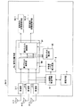
無線通信装置3は、複数(M個)のアンテナ4−1〜M、複数のアンテナ4−1〜Mで受信した各高周波信号を増幅処理、フィルタリング処理及びベースバンド信号への周波数変換処理を施し、各々をディジタル信号として取り出す受信部5−1〜M、受信部5の出力を基に干渉源無線通信装置2−1〜Sからの干渉信号を選択的に受信する干渉信号受信手段6、干渉信号を選択的に受信するための干渉波受信情報を記憶する記憶手段7、干渉信号受信手段6の出力を基に干渉波の受信レベルを検出する干渉波レベル検出手段8、所望無線通信装置1から送信されたNt個(ただし、Nt≧1)の送信系列を、複数アンテナ4で受信した受信信号から分離合成受信する信号分離手段9、及び分離受信したNt個の信号系列に対し、復調及び復号処理する信号系列受信処理手段10−1〜Ntを有して構成される。
The
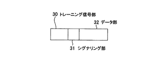
本実施形態では、送信信号は無線LAN等で用いられるパケット伝送による通信信号を仮定しており、図2は通信信号のパケット構成の一例を示す図である。図2において、送信信号として伝送されるパケットは、予め既知の信号系列からなるトレーニング信号部(プリアンブル部)30、シグナリング部31、及びデータ部32を有してなる。トレーニング信号部30は、受信部5での増幅処理時の自動利得制御(AGC)、周波数同期、シンボルタイミング同期及び伝送路歪みの等化などに用いられる。シグナリング部31は、後続するデータ部32の送信元及び送信先の無線通信装置の固有識別信号、誤り訂正符号の符号化率、変調多値数等の情報を含む。
In this embodiment, the transmission signal is assumed to be a communication signal by packet transmission used in a wireless LAN or the like, and FIG. 2 is a diagram illustrating an example of a packet configuration of the communication signal. In FIG. 2, a packet transmitted as a transmission signal includes a training signal unit (preamble unit) 30, a
図3は、パケット伝送状況を説明する模式図であり、所望無線通信装置1から送信される自局宛パケット40に対する干渉源無線通信装置2からの送信信号タイミングを示している。干渉源無線通信装置2は、それぞれの備えたアンテナから同一チャネル干渉波となる電波を送信するが、常に全ての干渉源無線通信装置2から送信されているわけではなく、それぞれの送信タイミングで、異なるパケットサイズで、バースト的に送信される。図3において、Case1では、自局宛パケット40より大きいサイズの干渉源無線通信装置2の送信パケット41が伝送され、Case2、Case3では、自局宛パケット40より小さいサイズの干渉源無線通信装置2の送信パケット42、43が、異なるタイミングで伝送されている例を示す。
FIG. 3 is a schematic diagram for explaining the packet transmission situation, and shows the transmission signal timing from the interference source
すなわち、Case1のように自局宛パケット40に対して、全期間に渡り干渉波の送信パケット41が存在する場合もあるし、Case2、Case3のように、自局宛パケット40の一部の期間に、干渉波の送信パケット42、43が存在する場合もある。送信パケット42が存在する期間T1と、送信パケット43が存在する期間T2とでは、干渉波の状態が変化する。このような状況において、干渉源無線通信装置2からの同一チャネル干渉波の送信状況が、無線通信装置3の干渉除去能力の範囲であれば、自局宛のパケットの受信が成功するが、干渉除去能力を超えた場合はパケット受信に失敗し、再送動作を行うことなる。
That is, there are cases where there is an interference
以下では、干渉源無線通信装置2からの同一チャネル干渉波の送信状況が、無線通信装置3の干渉除去能力の範囲であることを前提に、図1及び図4を用いて、その動作を説明する。図4は、無線通信装置3の自局宛パケットの受信時の動作を示すフローチャートである。なお、パケットはアクセスポイント間で、非同期に転送されるため、干渉源はランダム的に発生する。このため、図4の受信時動作は、繰り返し行われるものである。本実施形態は、干渉波の指向性、すなわち空間的な位置はほぼ一定であり、干渉波が非定常に発生して時間的に変化する場合に特に有効なものであり、このような場合を想定した動作を示している。例えば、無線LANなどのように各通信装置が自立分散的に動作し、ランダムにパケットが伝送される場合などに相当する。
Hereinafter, the operation will be described with reference to FIGS. 1 and 4 on the assumption that the transmission state of the co-channel interference wave from the interference source
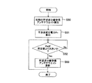
まず、使用する周波数チャネルで、伝送パケットの有無を検出する(S21)。伝送パケットが存在する場合、そのトレーニング信号部に含まれる予め既知のトレーニング信号を用いて、周波数同期及びタイミング同期を確立し、さらに伝送路歪みを等化することで、トレーニング信号に続く伝送パケットのシグナリング部に含まれているパケット送信元及び送信先のアドレス情報を読みとり、自局宛のパケットであるかを検出する(S22)。ここで、自局宛以外のパケットを受信した場合、干渉波であるため、その干渉信号を学習する前処理モードへ移行(S23)し、自局宛のパケットを受信した場合、その送信信号を受信する受信処理モードへ移行する(S24)。 First, the presence / absence of a transmission packet is detected in the frequency channel to be used (S21). When there is a transmission packet, the previously known training signal included in the training signal portion is used to establish frequency synchronization and timing synchronization and further equalize the transmission path distortion, so that the transmission packet that follows the training signal The address information of the packet transmission source and the transmission destination included in the signaling unit is read to detect whether the packet is addressed to the own station (S22). Here, when a packet other than that addressed to the local station is received, since it is an interference wave, the process proceeds to a pre-processing mode for learning the interference signal (S23). The process proceeds to the reception processing mode for receiving (S24).
前処理モード(S23)では、干渉信号受信手段6において、トレーニング信号部の干渉相関行列RIを算出し、これを干渉波受信情報として記憶手段7において記憶する。ここで、干渉相関行列RInは、第n番目の自局宛以外のパケットを受信した時の干渉相関行列を示し、トレーニング信号を用いて算出される伝送路歪み(以下、チャネル推定値)hn(j、k)を用いて算出する。ここでhn(j、k)は、第n番目の干渉源無線通信装置2−nの第k番目のアンテナから送信され、無線通信装置3の第j番目のアンテナ4−jで受信する際のチャネル推定値を表す。なお、第n番目の干渉源無線通信装置2−nは、NIt(n)個のアンテナをもち、NIt(n)は1以上の自然数とする。フラットフェージング伝送路を仮定した場合、第n番目の自局宛以外のパケットを受信した場合の干渉相関行列RInは、下記(数1)のように算出される。
In the preprocessing mode (S23), the interference signal receiving means 6 calculates the interference correlation matrix RI of the training signal section, and stores this as interference wave reception information in the storage means 7. Here, the interference correlation matrix RI n indicates an interference correlation matrix when a packet other than the n-th own station address is received, and transmission path distortion (hereinafter referred to as channel estimation value) h calculated using the training signal. n (j, k) is used for calculation. Here, h n (j, k) is transmitted from the k th antenna of the n th interference source radio communication device 2-n and received by the j th antenna 4-j of the
![]()
![]()
ここで、B(n)はM行NIt(n)列の行列であり、その第j行k列の要素はhn(j、k)からなる。上付きの添え字Hはベクトル共役転置演算子を示す。また、Pnは雑音電力推定値、EMはM次の単位行列を示す。 Here, B (n) is a matrix having M rows and NIt (n) columns, and the elements in the j-th row and k-th column are h n (j, k). The superscript H indicates a vector conjugate transpose operator. P n is a noise power estimation value, and E M is an M-th order unit matrix.
なお、干渉相関行列RIの別な算出方法として、トレーニング信号を用いて算出されるチャネル推定値を用いずに算出する方法もある。この場合、下記の(数2)を用いる。 As another method for calculating the interference correlation matrix RI, there is a method for calculating without using a channel estimation value calculated using a training signal. In this case, the following (Equation 2) is used.

ここで、x(t、n)はM次の列ベクトルであり、第j番目の要素は、無線通信装置3の第j番目のアンテナ4−jで、第n番目の自局宛以外のパケットを受信した場合のベースバンド信号を時刻tでサンプリングされた信号を示す。また、dtはサンプリング時間間隔、t0はサンプリング開始時刻、Nsはサンプリングされたデータ数である。この場合、干渉相関行列RIは、パイロット信号を用いずに算出することができるため、データ部の信号を用いても算出することが可能である。データ部に含まれる信号が十分長い場合は、干渉相関行列RIを精度よく推定することができる。
Here, x (t, n) is an M-th column vector, and the j-th element is the j-th antenna 4-j of the
以上のように得られた干渉相関行列RInを用いて、記憶手段7において記憶内容を更新する。更新手法として、以下のような3つの手法のいずれか、または、複数を組み合わせて用いる。 Using the interference correlation matrix RI n obtained as described above, the storage contents are updated in the storage means 7. As the update method, one of the following three methods or a combination of a plurality of methods is used.
1)重み付け平均化した干渉相関行列を算出する。
この場合、重み付け平均化した干渉相関行列に基づく干渉波受信アンテナウエイトにより干渉信号を受信することができるため、干渉信号受信手段6及び記憶手段7の構成を簡易化することが可能となる。一方、重み付け平均化された干渉相関行列を用いた所望波分離受信アンテナウエイトによる受信信号は、所望波信号を受信すると共に、前処理モードにおいて受信された強勢なレベルの干渉信号を常に優先的に抑圧する動作となり、個々の干渉信号を最適なレベルまで抑圧して受信することはできない。よって、この方法は万能であるものの、干渉波を十分に抑圧できない場合がある。
1) A weighted averaged interference correlation matrix is calculated.
In this case, since the interference signal can be received by the interference wave receiving antenna weight based on the weighted averaged interference correlation matrix, the configuration of the interference signal receiving means 6 and the storage means 7 can be simplified. On the other hand, the received signal by the desired wave separation receiving antenna weight using the weighted average interference correlation matrix receives the desired wave signal, and always gives priority to the strong level interference signal received in the preprocessing mode. The operation is suppressed, and individual interference signals cannot be received with being suppressed to an optimum level. Therefore, although this method is versatile, there are cases where interference waves cannot be sufficiently suppressed.
2)干渉相関行列RInを、個別に、そのまま記憶させる。記憶できる干渉相関行列数が所定数NIを超えた場合、受信電力が高い干渉相関行列RIkを、順に、所定数NI個分の干渉相関行列を記憶する。ただし、kはNI以下の自然数を示す。
この場合、複数の干渉相関行列RInに対し、干渉波受信アンテナウエイトを設けて干渉信号を受信する構成となるため、干渉信号受信手段6及び記憶手段7の構成は複雑化する。一方、重み付け平均化された干渉相関行列を用いた所望波分離受信アンテナウエイトによる受信信号は、所望波信号を受信すると共に、前処理モードにおいて受信された強勢なレベルの干渉信号のそれぞれに対し、十分なレベルまで抑圧して受信することが可能となる。
2) The interference correlation matrix RI n is stored individually as it is. When the number of interference correlation matrices that can be stored exceeds a predetermined number NI, an interference correlation matrix RI k having a high received power is sequentially stored for a predetermined number NI. However, k shows a natural number below NI.
In this case, since the interference wave receiving antenna weight is provided for the plurality of interference correlation matrices RI n to receive the interference signal, the configurations of the interference
3)送信元のアドレス情報毎に分類して、干渉相関行列RInを個別に記憶させる。同じ送信元のアドレスである干渉相関行列が複数検出された場合は、重み付け平均化後に記憶する。また、記憶できる干渉相関行列数が所定数NIを超えた場合、受信電力が高い干渉相関行列RIkの送信元のアドレス情報を優先して、所定数NI個分の干渉相関行列を記憶する。ただし、kはNI以下の自然数を示す。
この場合、2)の効果に加え、一つの送信元に対応して、一つの干渉相関行列を記憶手段7において記憶することができる。これにより、1つの送信元に対し、複数の干渉波受信アンテナウエイトを設けて干渉信号を受信することが無くなり、干渉信号受信手段6及び記憶手段7のそのような重複による構成の複雑化を避けることができる。また、送信元の空間的変動がない場合、共通な送信元毎に平均化処理を加えるため干渉相関行列の雑音成分を低減でき、その結果、その干渉相関行列を用いた所望波分離受信アンテナウエイトによる干渉抑圧効果を高めることができる。よって、この方法が一番効率的に干渉波を十分なレベルまで抑圧できる。
3) The interference correlation matrix RI n is individually stored by classifying each address information of the transmission source. If a plurality of interference correlation matrices that are the same source address are detected, they are stored after weighted averaging. Further, when the number of interference correlation matrices that can be stored exceeds a predetermined number NI, the address correlation information of the interference correlation matrix RI k having a high received power is preferentially stored, and the interference correlation matrices for the predetermined number NI are stored. However, k shows a natural number below NI.
In this case, in addition to the effect of 2), one interference correlation matrix can be stored in the storage means 7 corresponding to one transmission source. Accordingly, a plurality of interference wave receiving antenna weights are not provided for one transmission source, and interference signals are not received, and the configuration of the interference signal receiving means 6 and the storage means 7 due to such duplication is avoided. be able to. In addition, when there is no spatial variation of the transmission source, the noise component of the interference correlation matrix can be reduced because averaging processing is performed for each common transmission source. As a result, the desired wave separation receiving antenna weight using the interference correlation matrix is reduced. The interference suppression effect by the can be enhanced. Therefore, this method can most effectively suppress the interference wave to a sufficient level.
なお、十分な電力レベルの信号があるにもかかわらず、伝送パケットのシグナリング部の情報が読みとれないような異種の通信システムからの干渉が存在する場合は、上記(数2)で示すようにトレーニング信号によるチャネル推定値を用いない干渉相関行列RIを算出し、記憶手段7を更新し、再度、S21にもどり、伝送パケットの有無を確認する。そして、干渉波が複数ある場合は他の干渉波についても同様の処理を繰り返す。 If there is interference from a different type of communication system in which the information of the signaling part of the transmission packet cannot be read despite the presence of a signal with a sufficient power level, training is performed as shown in (Equation 2) above. The interference correlation matrix RI that does not use the channel estimation value based on the signal is calculated, the storage means 7 is updated, and the process returns to S21 again to check whether there is a transmission packet. If there are a plurality of interference waves, the same processing is repeated for other interference waves.
以上の自局宛以外のパケットを受信した場合の干渉相関行列RIを記憶するまでの処理が、前処理モード(S23)である。 The process up to storing the interference correlation matrix RI when receiving a packet other than those addressed to the own station is the preprocessing mode (S23).
次に、受信処理モードへ移行(S24)した場合の動作説明を行う。なお、以下では、トレーニング信号部のトレーニング信号を用いた周波数同期、位相同期、シンボル同期確立後の動作を説明する。無線通信装置3における複数アンテナ4で受信された高周波信号は、それぞれ受信部5−1〜Mにおいて、増幅処理、フィルタリング処理及び周波数変換処理の後に直交検波され、IQ平面上のベースバンド信号に変換される。このベースバンド信号を、A/D変換器を用いて複素ディジタル信号で表現される受信信号ベクトルy(k)として出力する。以下、kはサンプリングされた信号の離散時刻を示す。
Next, the operation when the mode is shifted to the reception processing mode (S24) will be described. In the following, operations after establishing frequency synchronization, phase synchronization, and symbol synchronization using the training signal of the training signal unit will be described. The high-frequency signals received by the plurality of
この場合、所望無線通信装置1のNt個の各アンテナから送信される送信系列xn(k)からなる送信系列ベクトルx(k)=[x1(k)、...、xNt(k)]Tに対し(上付き添え字Tはベクトル転置演算子)、フラットフェージング伝搬路を通して得られる離散時刻kにおける無線通信装置3での受信信号ベクトルy(k)は、下記(数3)のように示される。
In this case, transmission sequence vectors x (k) = [x 1 (k),... Consisting of transmission sequences x n (k) transmitted from the Nt antennas of the desired
![]()
![]()
ここで、y(k)は受信に用いるM個のアンテナ4での受信信号を要素として含む列ベクトルであり、アンテナ4−mで受信された信号ym(k)を第m番目の要素とする。また、H1は所望無線通信装置1の送信系列x(k)が受ける伝搬路変動を示すチャネル応答行列である。ここで、H1は(無線通信装置3のアンテナ数M)行×(所望無線通信装置1における送信アンテナ数Nt)列からなる行列であり、そのi行j列の行列要素hijは、所望無線通信装置1における第j番目の送信アンテナから送信された信号xj(k)が、無線通信装置3における第i番目のアンテナ4−iで受信される場合の伝搬路変動を示す。
Here, y (k) is a column vector including elements received by the
また、n(k)は無線通信装置3のM個の受信アンテナ4で受信時に付加される雑音成分ベクトルである。また、I(k)は干渉源無線通信装置2−1〜Sのうち一つまたは複数から送信される干渉信号成分を表す。なお、干渉源無線通信装置2からの送信信号が存在しない場合はI(k)=0となる。
Further, n (k) is a noise component vector added at the time of reception by the
このような無線通信装置3の受信信号ベクトルy(k)は、干渉信号受信手段6及び信号分離手段9に入力される。
Such a received signal vector y (k) of the
干渉信号受信手段6は、記憶手段7から前処理モードで得られた一つまたは複数の干渉相関行列RInを読み出し、干渉信号電力I(k)を、空間的なフィルタリングにより選択的に受信できる干渉波受信アンテナウエイトベクトルWInを算出する。なお、干渉相関行列RInが複数あれば、複数の出力zn(k)を算出して、後述する干渉波レベル検出手段8で、しきい判定することで、干渉波の特定を行う。この干渉波受信アンテナウエイトベクトルWInは、干渉信号を最大化するような(干渉波のSINRが最大となる)アンテナウエイトとなる。そして、下記(数4)で示すように受信信号ベクトルy(k)との積和演算を行い、第n番目の干渉波成分信号zn(k)を抽出する。 The interference signal receiving means 6 can read out one or a plurality of interference correlation matrices RI n obtained in the preprocessing mode from the storage means 7 and selectively receive the interference signal power I (k) by spatial filtering. calculating the interference wave receiving antenna weight vector WI n. If there are a plurality of interference correlation matrices RI n , a plurality of outputs z n (k) are calculated, and the interference wave level detection means 8 (to be described later) performs threshold determination to identify the interference wave. The interference wave receiving antenna weight vector WI n, such as to maximize the interference signal (SINR of the interference wave is maximum) the antenna weight. Then, as shown in the following (Equation 4), a product-sum operation with the received signal vector y (k) is performed to extract the nth interference wave component signal z n (k).
![]()
![]()
ここで、nは記憶手段7で記憶された干渉相関行列の個数NI以下の自然数であり、zn(k)は、干渉源無線通信装置2が送信した空間多重ストリーム数の要素を持つ列ベクトルからなる。また、上付きの添え字Hはベクトル共役転置演算子を示す。ここで、空間多重ストリーム数とは、例えば、次世代の無線LAN規格IEEE801.11nにおいてMIMO(Multiple-Input Multiple-Output)による空間多重伝送を行う場合に、1つの信号(パケット)を複数のデータストリームに分割して空間的に多重して伝送するようなことが行われ、このときのデータストリームの数に相当する。
Here, n is a natural number equal to or less than the number NI of interference correlation matrices stored in the
なおこのとき、干渉波受信アンテナウエイトベクトルWInの算出は以下のような手法を適用する。
1)[方式1]干渉波受信アンテナウエイトベクトルWInとして下記の(数5)を用いる。
At this time, calculation of the interference wave receiving antenna weight vector WI n applies techniques such as follows.
1) [Method 1] The following (Formula 5) is used as the interference wave receiving antenna weight vector WI n .
![]()
![]()
ここで、Uk (n)は、干渉相関行列RInを固有値分解して得られるM個の固有値の内、干渉源無線通信装置2が送信した空間多重ストリーム数の分、大きい順に固有値を取り出し、それに対応する固有ベクトルを列ベクトル成分に持つ。ここでk=1、...、Mである。これにより、干渉相関行列RInの生成時に到来していた干渉波の電力を最大化するように干渉波を受信することができる。
Here, U k (n) extracts eigenvalues in descending order of the number of spatially multiplexed streams transmitted by the interference source
また、記憶手段7における動作を変更することで、別な干渉波受信アンテナウエイトベクトルWInの算出として以下のような手法の適用が可能である。
2)[方式2]前処理モードにおいて得られるRInを記憶手段7において記憶する代わりに、前処理モードにおいて得られるB(n)を記憶させる。この場合、干渉波受信アンテナウエイトベクトルWInとして、下記の(数6)を用いる。
Further, by changing the operation of the
2) [Method 2] Instead of storing RI n obtained in the preprocessing mode in the storage means 7, B (n) obtained in the preprocessing mode is stored. In this case, as the interference wave receiving antenna weight vector WI n, using the following (Formula 6).
![]()
![]()
ここで、Dnは、下記の(数7)により算出され、Heは所望無線通信装置1の送信系列x(k)が受ける伝搬路応答行列H1の推定値であり、δは雑音電力推定値、EMはM次の正方行列を示す(ただし、Mは無線通信装置3における受信アンテナブランチ数)。これにより、所望信号を抑圧した上で、干渉相関行列RInの生成時に到来していた干渉波の電力を選択的に受信することができる。
Here, D n is calculated by (Equation 7) below, H e is the estimate of the channel response matrix H 1 of the desired
![]()
![]()
一方、信号分離手段9は、受信信号ベクトルy(k)を入力として、所望無線通信装置1から送信される送信系列xn(k)を、所望波分離受信アンテナウエイトWDnを用いて、WDn Hy(k)とすることで分離受信する。ここで、nはNt以下の自然数であり、Nt≧1である。すなわち、Nt=1の場合は、いわゆるダイバーシチ受信動作を行い、Nt>1の場合は、空間多重伝送された送信信号を分離受信するSDM受信動作となる。以下に信号分離手段9を中心にした所望波の分離受信動作について説明する。
On the other hand, the signal separation means 9 receives the received signal vector y (k) as an input, and transmits the transmission sequence x n (k) transmitted from the desired
図5は信号分離手段9及び干渉波レベル検出手段8を含めた動作を示すフローチャートである。以下図5を用いて、その動作説明を行う。
FIG. 5 is a flowchart showing the operation including the signal separating means 9 and the interference wave
まず、初期の所望波分離受信アンテナウエイトWDとして下記の(数8)を算出する(S50)。この所望波分離受信アンテナウエイトWDは、所望波のSINRが最大となるようなアンテナウエイトとなる。 First, the following (Equation 8) is calculated as the initial desired wave separation receiving antenna weight WD (S50). The desired wave separation receiving antenna weight WD is an antenna weight that maximizes the SINR of the desired wave.
![]()
![]()
ここで、WDはM行Nt列の行列からなりその第n列はWDnからなる。Rnは、下記の(数9)により算出される。また、Heは所望無線通信装置1の送信系列x(k)が受ける伝搬路応答行列H1の推定値、δは雑音電力推定値、ENtはNt次の正方行列を示す(ただし、Mは無線通信装置3における受信アンテナブランチ数)。なお、伝搬路応答行列H1の推定値He及び雑音電力推定値δは、自局宛のパケット信号におけるトレーニング信号部の既知信号系列から推定値を得る。
Here, WD its n-th column consists matrix of M rows Nt columns consists WD n. R n is calculated by the following (Equation 9). Also, H e is the desired
![]()
![]()
なお、上記はMMSE手法に基づく信号分離手法であるが、これに限定されず、ZF、MLD(Maximum likelihood Detection)等の手法の適用も可能である。 Although the above is a signal separation method based on the MMSE method, the present invention is not limited to this, and methods such as ZF and MLD (Maximum likelihood Detection) can also be applied.
次に、干渉波レベル検出手段8は、干渉信号受信手段6の出力zn(k)に基づき干渉波成分電力Pn=||zn(k)||2を検出し、干渉波成分電力Pnが所定値LIを超えた場合(S51)、信号分離手段9における所望波分離受信アンテナウエイトWDを更新する(S52)。一方、干渉波成分電力Pnが所定値LIを超えない場合、信号分離手段9における所望波分離受信アンテナウエイトWDを更新せずに維持する(S53)。例えば、図3に示したように、Case1、Case2、Case3のように干渉波が発生する場合、Case2、Case3が、順次発生する期間T1とT2との間で、所望波分離受信アンテナウエイトWDを変更すればよい。
Next, the interference wave level detection means 8 detects the interference wave component power P n = || z n (k) || 2 based on the output z n (k) of the interference signal reception means 6, and the interference wave component power. When P n exceeds the predetermined value LI (S51), the desired wave separation receiving antenna weight WD in the signal separation means 9 is updated (S52). On the other hand, when the interference wave component power Pn does not exceed the predetermined value LI, the desired wave separation receiving antenna weight WD in the signal separation means 9 is maintained without being updated (S53). For example, as shown in FIG. 3, when interference waves are generated as in
干渉波レベル検出手段8は、所望波分離受信アンテナウエイトWDを更新する場合、以下のような新たな所望波分離受信アンテナウエイトWDを算出し、信号分離手段9に結果を出力する。 When the desired wave separation receiving antenna weight WD is updated, the interference wave level detection means 8 calculates a new desired wave separation reception antenna weight WD as described below, and outputs the result to the signal separation means 9.
1)[方式3]: 上述した[方式1]における干渉波受信アンテナウエイトベクトルWInとして上記(数5)を用いた場合、下記の(数10)に基づいて、所望波分離受信アンテナウエイトWDを更新する。 1) [Method 3]: When the above (Equation 5) is used as the interference wave receiving antenna weight vector WI n in [Method 1], the desired wave separation receiving antenna weight WD is obtained based on the following (Equation 10). Update.
![]()
![]()
ここで、Wbは下記の(数11)により算出され、またvk (n)は、干渉相関行列RInを固有値分解して得られるM個の固有値を、小さい順にNt個取り出したときの固有値に対応する固有ベクトル(ただしk=1、...、Nt)であり、Qnは下記の(数12)により与えられる。この所望波分離受信アンテナウエイトWDは、所望波の電力を最大化するとともに、対応する干渉波を所定レベル以下に抑圧するようなアンテナウエイトとなる。これにより、干渉相関行列RInの生成時に起因する干渉波を抑圧した上で、所望信号を選択的に受信することができる。なお、所定値LIを超える干渉波成分電力が複数ある場合(Pn0,Pn1,...)、当該の干渉相関行列(RIn0,RIn1,...)を加算合成した干渉相関行列RIn(= a0RIn0+a1RIn1+...)を用いる(ただし、a0、a1、...は重み係数)。すなわち、各干渉波成分に対応する干渉相関行列毎に重み付けをして、合成する形となる。 Here, W b is calculated by the following (Equation 11), and v k (n) is obtained when Nt eigenvalues obtained by eigenvalue decomposition of the interference correlation matrix RI n are extracted in ascending order. An eigenvector corresponding to the eigenvalue (where k = 1,..., Nt), and Q n is given by (Equation 12) below. The desired wave separation receiving antenna weight WD is an antenna weight that maximizes the power of the desired wave and suppresses the corresponding interference wave to a predetermined level or less. As a result, it is possible to selectively receive a desired signal while suppressing an interference wave caused when the interference correlation matrix RI n is generated. When there are a plurality of interference wave component powers exceeding the predetermined value LI (P n0 , P n1 ,...), An interference correlation matrix obtained by adding and synthesizing the interference correlation matrix (RI n0 , RI n1 ,...). RI n (= a 0 RI n0 + a 1 RI n1 +...) Is used (where a 0 , a 1 ,... Are weighting factors). That is, the interference correlation matrix corresponding to each interference wave component is weighted and combined.
![]()
![]()
![]()
![]()
2)[方式4]: 上述した[方式2]における前処理モードにおいて得られるRInを、記憶手段7において記憶する代わりに、前処理モードにおいて得られるB(n)を記憶させ、干渉波受信アンテナウエイトベクトルWInとして上記(数6)を用いた場合、下記の(数13)に基づいて所望波分離受信アンテナウエイトWDを更新する。 2) [Method 4]: Instead of storing RI n obtained in the preprocessing mode in [Method 2] described above in the storage means 7, B (n) obtained in the preprocessing mode is stored, and interference wave reception is performed. When the above (Equation 6) is used as the antenna weight vector WI n , the desired wave separation receiving antenna weight WD is updated based on the following (Equation 13).
![]()
![]()
ここで、Wbは下記の(数14)で、Fnは下記の(数15)で、Qnは下記の(数16)により示される。なお、(数15)における定数aは、干渉抑圧効果を可変するパラメータであり、aが大きくなるほど、所望波受信電力を高めるよりも干渉抑圧を優先する空間フィルタリング動作となる。この所望波分離受信アンテナウエイトWDは、所望波の電力を最大化するとともに、対応する干渉波を所定レベル以下に抑圧するようなアンテナウエイトとなる。これにより、干渉相関行列RInの生成時に起因していた干渉波を抑圧した上で、所望信号を受信することができる。なお、所定値LIを超える干渉波成分電力が複数ある場合(Pn0,Pn1,...)、当該の干渉チャネル応答行列(B(n0),B(n1),...)から生成される相関行列を加算合成した相関行列B(n)BH(n)(= a0B(n0)BH(n0)+a1B(n1)BH(n1)+...)を用いる(ただし、a0、a1、...は重み係数)。すなわち、各干渉波成分に対応する干渉相関行列ごとに重み付けをして合成する形となる。 Here, W b is represented by the following (Equation 14), F n is represented by the following (Equation 15), and Q n is represented by the following (Equation 16). The constant a in (Equation 15) is a parameter that varies the interference suppression effect. As a increases, the spatial filtering operation prioritizes interference suppression over increasing the desired wave reception power. The desired wave separation receiving antenna weight WD is an antenna weight that maximizes the power of the desired wave and suppresses the corresponding interference wave to a predetermined level or less. As a result, it is possible to receive the desired signal while suppressing the interference wave caused when the interference correlation matrix RI n is generated. When there are a plurality of interference wave component powers exceeding the predetermined value LI (P n0 , P n1 ,...), The interference channel response matrix (B (n 0 ), B (n 1 ),...) Correlation matrix B (n) B H (n) (= a 0 B (n 0 ) B H (n 0 ) + a 1 B (n 1 ) B H (n 1 ) + (Where a 0 , a 1 ,... Are weighting factors). That is, the interference correlation matrix corresponding to each interference wave component is weighted and combined.
![]()
![]()
![]()
![]()
![]()
![]()
なお、信号分離手段9は、所望波分離受信アンテナウエイトWDの乗算を、2つのウエイト乗算部に分けて実施してもよい。以下、その構成の説明を行う。図6は、信号分離手段を2つのウエイト乗算部に分けて構成した無線通信装置の第1変形例の構成を示すブロック図である。図6に示す第1変形例の無線通信装置3b−1において、信号分離手段9aは、第1のウエイト乗算部90と第2のウエイト乗算部91とを有して構成される。
The signal separation means 9 may perform the multiplication of the desired wave separation reception antenna weight WD by dividing it into two weight multiplication sections. Hereinafter, the configuration will be described. FIG. 6 is a block diagram showing a configuration of a first modification of the wireless communication apparatus in which the signal separation means is divided into two weight multiplication sections. In the
第1のウエイト乗算部90で用いるウエイトは、(数10)または(数13)に示すように所望波分離受信アンテナウエイトWDにおけるWbで示され、無線通信装置3b−1の受信信号ベクトルy(k)に対し、A(k)=Wb Hy(k)となるように乗算する。これにより、受信信号ベクトルy(k)に含まれる干渉波の受信電力を抑圧した信号を得ることができる。
The weight used in the
次に、第2のウエイト乗算部91で用いるウエイトは、(数10)または(数13)に示すように所望波分離受信アンテナウエイトWDにおける(Qn −1)Hを、第1のウエイト乗算部の出力A(k)に対して、(Qn −1)HA(k)となるように乗算する。これにより、受信信号ベクトルy(k)に含まれる干渉波の受信電力を抑圧した信号A(k)から、Nt個の所望波信号を分離受信することができる。
Next, the weight used in the second
なお、所望波の空間多重数が1である場合は、信号電力を最大化する最大比合成ウエイトを用いる。これにより、複数アンテナ受信によるダイバーシチ効果を高めることで、受信品質を高めることができる。 When the desired wave spatial multiplexing number is 1, the maximum ratio combining weight that maximizes the signal power is used. Thereby, the reception quality can be improved by increasing the diversity effect due to the reception of multiple antennas.
このように信号分離手段9aを2つのウエイト乗算部に分けて構成することで、第1のウエイト乗算部90において、干渉波を低減した出力信号A(k)を取り出すことができる。この性質を用いて、干渉波信号の影響を低減した信号を用いて、チャネル推定値を再度算出する構成を用いることが可能となる。
In this way, by dividing the signal separating means 9a into two weight multipliers, the
図7は、チャネル推定値を再度算出するようにした無線通信装置の第2変形例の構成を示すブロック図である。図7に示す第2変形例の無線通信装置3b−1において、再チャネル推定部95は、干渉波の低減した出力信号A(k)に含まれるチャネル推定用の予め既知であるパイロット信号を抽出して、チャネル推定を行う。これにより得られたチャネル推定値Hrを用いて、第2のウエイト乗算部91で用いるウエイトを算出する。
FIG. 7 is a block diagram showing a configuration of a second modified example of the wireless communication apparatus in which the channel estimation value is calculated again. In
ここで、再チャネル推定部95は、上述した所望波分離受信アンテナウエイトWDの更新方法のうち、[方式3]の場合は(数12)の代わりに下記(数17)に示されるQnを用いて、所望波分受信用のウエイトを算出する。また、[方式4]の場合は(数16)の代わりに下記(数18)に示されるQnを用いて、所望波分受信用のウエイトを算出する。
Here, the
![]()
![]()
![]()
![]()
このように、干渉波信号成分を低減した信号を用いて、チャネル推定値を算出することによって、所望波分離するウエイトをより正確に求めることができる。これにより、所望波に対する受信品質を高めることができる効果が得られる。 Thus, by calculating a channel estimation value using a signal with reduced interference wave signal components, the weight for separating the desired wave can be obtained more accurately. Thereby, the effect which can improve the reception quality with respect to a desired wave is acquired.
また、さらに、第1のウエイト乗算部におけるウエイトを、複数アンテナM個の内、Mより小さいk個からなるサブアレーの組にして、干渉波受信電力を抑圧するウエイトを生成してもよい。 Furthermore, the weights in the first weight multiplication unit may be set to a set of sub-arrays consisting of k smaller than M out of the plurality of M antennas, and a weight for suppressing the interference wave reception power may be generated.
図8は、信号分離手段の第1のウエイト乗算部におけるウエイトを複数のサブアレーの組にして構成した無線通信装置の第3変形例の構成を示すブロック図である。図8に示す第3変形例の無線通信装置3b−3において、信号分離手段9bに含まれる第1のウエイト乗算部90は、さらに、複数のサブアレーウエイト乗算部92を備える。ここで、図8ではアンテナ数M=3の時に、M=3のアンテナからk=2のサブアレーのアンテナ数を構成する場合の例を示している。この場合、3(=3C2)通りのサブアレーの組み合わせがあるため、3つのサブアレーウエイト乗算部92−1〜92−3を有する。第m番目のサブアレーウエイトの生成は、(数11)あるいは(数14)で示されるWbの算出時に当該のアンテナ番号に関わる行列またはベクトル要素を取り出した形で置換することによって算出することができる。
FIG. 8 is a block diagram showing a configuration of a third modification of the wireless communication apparatus in which the weights in the first weight multiplication section of the signal separation means are configured as a set of a plurality of subarrays. In the
このように、干渉波受信電力を抑圧するウエイトWbの生成時には、固有値分解や、逆行列演算が含まれるが、サブアレー化して、行列の次数を下げることで、演算量を大幅に削減できるという効果が得られる。 As described above, when generating the weight W b for suppressing the interference wave reception power, eigenvalue decomposition and inverse matrix calculation are included. However, the calculation amount can be significantly reduced by reducing the order of the matrix by subarraying. An effect is obtained.
続いて、信号系列受信処理手段10は、信号分離手段9からのNt個の出力信号に対し、所定の変調方式によるシンボルデータ列からビットデータ列に変換するデマッピング処理、送信側で施されたインターリーブと逆の動作によりビット順を復元するデインタリーバ処理、入力されるビットデータ列に対し誤り訂正復号処理などを施し、送信ビット系列を復元する受信処理を行う。 Subsequently, the signal sequence reception processing means 10 is applied to the Nt output signals from the signal separation means 9 on the transmission side, a demapping process for converting a symbol data string into a bit data string by a predetermined modulation method. A deinterleaver process for restoring the bit order by an operation opposite to the interleaving process, an error correction decoding process for the input bit data string, and the like, and a reception process for restoring the transmission bit sequence are performed.
以上のような動作により、本実施形態では、非通信時には、前処理モードとして複数の干渉源無線通信装置2からの信号を予め受信しておき、その結果得られる干渉相関行列RIを基に、干渉源無線通信装置2からの送信信号を選択的に受信できる干渉波受信アンテナウエイトWIを準備する。
By the operation as described above, in the present embodiment, during non-communication, as a preprocessing mode, signals from a plurality of interference source
通信時には受信処理モードに移行し、通常受信すると共に、干渉波受信アンテナウエイトWIで受信された信号電力に基づき、干渉波成分の変動を検出し、干渉を与える干渉源無線通信装置2が出現、または変化した場合、新たな干渉相関行列を用いて干渉低減する所望波分離受信アンテナウエイトWDを適応的に変更することができる。
During communication, a transition is made to the reception processing mode, normal reception is performed, and based on the signal power received by the interference wave reception antenna weight WI, a variation in the interference wave component is detected, and an interference source
これにより、非定常に現れる干渉波に適応した空間的フィルタリングを実現でき、干渉除去能力を高めることで通信品質の安定化を図ることができる。例えば、異なる干渉波源から非定常に同一チャネル干渉が発生する場合でも、安定した受信品質を得ることができる。 Thereby, spatial filtering adapted to the interference wave appearing unsteady can be realized, and the communication quality can be stabilized by increasing the interference removal capability. For example, stable reception quality can be obtained even when co-channel interference occurs non-stationarily from different interference wave sources.
また、無線LANの通信システムにおいては、隠れ端末またはPCF(Point Coordination Function)動作をしている他BSS(Basic Service Set)からの同一チャネル干渉が存在した場合、所望でない送信元からの干渉信号を抑圧できない恐れがある。このような場合でも、本実施形態を適用すれば、シンボル同期が可能なレベルでの干渉を受けている場合に干渉耐性を向上することができ、伝送品質の向上が可能である。 Also, in a wireless LAN communication system, when there is co-channel interference from a hidden terminal or another BSS (Basic Service Set) performing a PCF (Point Coordination Function) operation, an interference signal from an undesired transmission source is transmitted. There is a fear that it cannot be suppressed. Even in such a case, if this embodiment is applied, interference tolerance can be improved when interference is received at a level where symbol synchronization is possible, and transmission quality can be improved.
なお、所望波分離受信アンテナウエイトを可変する場合の別な簡易的な手法として、受信信号y(n)の信号対干渉雑音電力比SIRを検出し、検出値が所定レベルを超える場合、干渉波受信アンテナウエイトベクトルWInを更新する動作としてもよい。この際の干渉波受信アンテナウエイトベクトルWInとしては、SIRが最大となるウエイトを選択する。 As another simple method for changing the desired wave separation receiving antenna weight, when the signal-to-interference noise power ratio SIR of the received signal y (n) is detected and the detected value exceeds a predetermined level, the interference wave An operation for updating the reception antenna weight vector WI n may be performed. The interference wave receiving antenna weight vector WI n at this time, selecting the weights SIR becomes maximum.
また、干渉相関行列RIの別な算出方法として、A)自局宛のパケット受信時に、トレーニング信号に無信号となるタイミングが含まれる場合、この無信号タイミングで、上記(数2)を用いて干渉相関行列を算出してもよい。これにより自局宛のパケット受信時に、同一チャネル干渉を与える干渉源の干渉相関行列を精度良く検出することができる。 Further, as another method for calculating the interference correlation matrix RI, A) When receiving a packet addressed to the own station and the timing at which no signal is included in the training signal, at the no signal timing, the above (Equation 2) is used. An interference correlation matrix may be calculated. This makes it possible to accurately detect the interference correlation matrix of the interference source that causes co-channel interference when receiving a packet addressed to the own station.
また、干渉相関行列RIのさらに別の算出方法として、B)自局宛のパケット受信時のデータ部において、上記(数2)を用いて得られる相関行列を用いてもよい。この場合、相関行列の算出するタイミング及び算出範囲をずらして、データ部で複数のブロックに分割し、それらを干渉相関行列RIとする。これにより、自局宛のパケット受信時に、同一チャネル干渉を与える干渉源の干渉相関行列を、時間的にずらしながら算出するため、干渉波源が時間的に変動する場合の追従性能を高めることができる。 As yet another method for calculating the interference correlation matrix RI, a correlation matrix obtained by using the above (Equation 2) may be used in the data part when receiving a packet addressed to the own station. In this case, the calculation timing and calculation range of the correlation matrix are shifted, and the data portion is divided into a plurality of blocks, which are set as an interference correlation matrix RI. Thereby, when receiving a packet addressed to the own station, the interference correlation matrix of the interference source that causes co-channel interference is calculated while being shifted in time, so that the follow-up performance when the interference wave source fluctuates in time can be improved. .
(第2の実施形態)
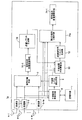
図9は、本発明の第2の実施形態における無線通信装置3aの構成を示す図である。第1の実施形態では、シングルキャリアを用いる伝送方式を用いたが、第2の実施形態では、マルチキャリア伝送としてOFDM(Orthogonal Frequency Division Multiplexing)を用いる無線通信システムに適用する例を示す。このため、無線通信装置3aは、第1の実施形態とは一部の構成が異なり、サブキャリア毎に処理系を備えている。
(Second Embodiment)
FIG. 9 is a diagram illustrating a configuration of the
第2の実施形態の無線通信装置3aは、サブキャリア毎に、干渉信号受信手段61−1〜Nc、記憶手段62−1〜Nc、信号分離手段64−1〜Ncを備えている。また、干渉波レベル検出手段63は、全ての干渉信号受信手段61−1〜Ncの出力結果を統合して、信号分離手段64−1〜Ncにおける所望波分離受信アンテナウエイトを更新するか判定する。すなわち、OFDMの全サブキャリアにおける干渉信号の受信結果を基に、干渉波成分のレベル検出を行い、このレベル検出結果に応じて所望波分離受信アンテナウエイトを可変する。その他の構成は第1の実施形態と同様であり、以下では第1の実施形態とは異なる部分の構成及び動作を主に説明する。なお、OFDM変調及び復調方法に関しては、文献(尾知博、上田健二 共著、「OFDMシステム技術とMATLABシミュレーション解説」、トリケップス、2002年)に情報開示されており、ここではその詳細説明は省略する。
The
第2の実施形態においても、第1の実施形態の図1に示すものと同様に、所望無線通信装置1及び所望無線通信装置1と同一または近接したキャリア周波数を用いるため干渉を与える干渉源無線通信装置2−1〜Sからの送信信号を、無線通信装置3aが受信するものとする。なお、無線通信装置3aは受信構成のみを示しており、送信構成の図示は省略している。
In the second embodiment as well, as shown in FIG. 1 of the first embodiment, the desired
無線通信装置3aにおいて、複数(M個)のアンテナ4−1〜Mでの受信信号を基にして、受信部5−1〜Mの出力が得られるまでの動作は、第1の実施形態と同様である。OFDM復調手段60−1〜Mは、それぞれ図示されていないGI(ガードインターバル)除去手段、IFFT手段、直列並列変換手段を含み、OFDM復調を施し、Nc個のサブキャリア毎のシンボルデータ系列を出力する。ここで、離散時刻kにおける第fs番目のサブキャリア毎のシンボルデータ系列をY(k、fs)と表記する。なお、Y(k、fs)は受信に用いるアンテナ数M個で受信された信号を要素として含む列ベクトルである。すなわち、アンテナ4−mで受信された信号ym(k、fs)を第m番目の要素とする。ただし、fs=1〜Ncである。
In the
以下、この信号を用いた動作を、第1の実施形態と同様に図4を用いて説明する。まず、使用する周波数チャネルで、伝送パケットの有無を検出する(S21)。伝送パケットが存在する場合、そのトレーニング信号部に含まれる予め既知のトレーニング信号を用いて、周波数同期及びタイミング同期を確立し、さらに伝送路歪みを等化することで、トレーニング信号に続く伝送パケットのシグナリング部に含まれているパケット送信元及び送信先のアドレス情報を読みとり、自局宛のパケットであるかを検出する(S22)。ここで、自局宛以外のパケットを受信した場合、干渉波であるため、その干渉信号を学習する前処理モードへ移行(S23)し、自局宛のパケットを受信した場合、その送信信号を受信する受信処理モードへ移行する(S24)。 Hereinafter, the operation using this signal will be described with reference to FIG. 4 as in the first embodiment. First, the presence / absence of a transmission packet is detected in the frequency channel to be used (S21). When there is a transmission packet, the previously known training signal included in the training signal portion is used to establish frequency synchronization and timing synchronization and further equalize the transmission path distortion, so that the transmission packet that follows the training signal The address information of the packet transmission source and the transmission destination included in the signaling unit is read to detect whether the packet is addressed to the own station (S22). Here, when a packet other than that addressed to the local station is received, since it is an interference wave, the process proceeds to a pre-processing mode for learning the interference signal (S23). The process proceeds to the reception processing mode for receiving (S24).
前処理モード(S23)では、サブキャリアfs毎に干渉信号受信手段61−fsにおいて、トレーニング信号部の干渉相関行列RI(fs)を算出し、記憶手段62−fsにおいて記憶する。ここで、干渉相関行列RIn(fs)は、第n番目の自局宛以外のパケットを受信した時の干渉相関行列を示し、トレーニング信号を用いて算出される伝送路歪み(以下、チャネル推定値)hn(j、k、fs)を用いて算出する。ここでhn(j、k、fs)は、第n番目の干渉源無線通信装置2−nの第k番目のアンテナから送信され、無線通信装置3aの第j番目のアンテナ4−jで受信する際のチャネル推定値を表す。なお、fs=1、...、Ncであり、第n番目の干渉源無線通信装置2−nは、NIt(n)個のアンテナをもち、NIt(n)は1以上の自然数とする。
In the preprocessing mode (S23), the interference signal reception means 61-fs calculates the interference correlation matrix RI (fs) of the training signal section for each subcarrier fs and stores it in the storage means 62-fs. Here, the interference correlation matrix RI n (fs) indicates an interference correlation matrix when a packet other than the n-th own station is received, and is a transmission path distortion calculated using a training signal (hereinafter, channel estimation). Value) Calculate using h n (j, k, fs). Here, h n (j, k, fs) is transmitted from the k-th antenna of the n-th interference source wireless communication device 2-n and received by the j-th antenna 4-j of the
ここで、干渉源無線通信装置2−1〜Sから送信される信号は、伝搬路におけるマルチパスの先行波からの相対的な遅延時間がガードインターバル(GI)範囲内であれば、周波数選択性フェージング環境を、サブキャリア単位ではフラットフェージング伝搬環境と等価に扱うことができる。このため、フラットフェージング伝送路を仮定した場合、第n番目の自局宛以外のパケットを受信した場合の干渉相関行列RIn(fs)は、下記(数19)のように算出される。 Here, the signals transmitted from the interference source radio communication apparatuses 2-1 to S have frequency selectivity as long as the relative delay time from the multipath preceding wave in the propagation path is within the guard interval (GI) range. The fading environment can be handled equivalently to the flat fading propagation environment on a subcarrier basis. For this reason, assuming a flat fading transmission path, the interference correlation matrix RI n (fs) when a packet other than that addressed to the n-th own station is received is calculated as shown in the following (Equation 19).
![]()
![]()
ここで、B(n、fs)はM行NIt(n)列の行列であり、その第j行k列の要素はhn(j、k、fs)からなる。上付きの添え字Hはベクトル共役転置演算子を示す。また、Pnは雑音電力推定値、EMはM次の単位行列を示す。 Here, B (n, fs) is a matrix with M rows and NIt (n) columns, and the elements of the jth row and the kth column are h n (j, k, fs). The superscript H indicates a vector conjugate transpose operator. P n is a noise power estimation value, and E M is an M-th order unit matrix.
なお、干渉相関行列RI(fs)の別な算出方法として、トレーニング信号を用いて算出されるチャネル推定値を用いずに算出する方法もある。この場合、下記の(数20)を用いる。 As another method of calculating the interference correlation matrix RI (fs), there is a method of calculating without using a channel estimation value calculated using a training signal. In this case, the following (Equation 20) is used.
ここで、Yn(k、fs)はM次の列ベクトルであり、第j番目の要素は、無線通信装置3aの第j番目のアンテナ4−jで、第n番目の自局宛以外のパケットを受信した場合のサブキャリアfsのベースバンド信号を時刻tでサンプリングされた信号を示す。また、dtはサンプリング時間間隔、t0はサンプリング開始時刻、Nsはサンプリングされたデータ数である。この場合、干渉相関行列RIは、パイロット信号を用いずに算出することができるため、データ部の信号を用いても算出することが可能である。データ部に含まれる信号が十分長い場合は、干渉相関行列RIを精度よく推定することができる。
Here, Y n (k, fs) is an M-th column vector, and the j-th element is the j-th antenna 4-j of the
以上のように得られた干渉相関行列RIn(fs)を用いて、サブキャリア毎の記憶手段62−fsにおいて記憶内容を更新する。更新手法として、第1の実施形態と同様、以下のような3つの手法のいずれか、または、複数を組み合わせて用いる。 Using the interference correlation matrix RIn (fs) obtained as described above, the storage contents are updated in the storage means 62-fs for each subcarrier. As the update method, as in the first embodiment, any one of the following three methods or a combination of a plurality of methods is used.
1)重み付け平均化した干渉相関行列を算出する。
2)干渉相関行列RIn(fs)を個別にそのまま記憶させる。記憶できる干渉相関行列数が所定数NIを超えた場合、受信電力が高い干渉相関行列RIk(fs)を順に所定数NI個分の干渉相関行列を記憶する。ただし、kはNI以下の自然数を示す。
3)送信元のアドレス情報毎に分類して、干渉相関行列RIn(fs)を個別に記憶させる。同じ送信元のアドレスである干渉相関行列が複数検出された場合は、重み付け平均化後に記憶する。また、記憶できる干渉相関行列数が所定数NIを超えた場合、受信電力が高い干渉相関行列RIk(fs)の送信元のアドレス情報を優先して所定数NI個分の干渉相関行列を記憶する。ただし、kはNI以下の自然数を示す。
これらの3つの手法のそれぞれの作用効果は、前述した第1の実施形態と同様である。
1) A weighted averaged interference correlation matrix is calculated.
2) The interference correlation matrix RI n (fs) is stored individually as it is. When the number of interference correlation matrices that can be stored exceeds a predetermined number NI, the interference correlation matrices for the predetermined number NI are sequentially stored as interference correlation matrices RI k (fs) having high received power. However, k shows a natural number below NI.
3) The interference correlation matrix RI n (fs) is individually stored for each address information of the transmission source. If a plurality of interference correlation matrices that are the same source address are detected, they are stored after weighted averaging. Further, when the number of interference correlation matrices that can be stored exceeds a predetermined number NI, the address information of the transmission source of the interference correlation matrix RI k (fs) with high reception power is preferentially stored for the predetermined number NI. To do. However, k shows a natural number below NI.
The operational effects of these three methods are the same as those of the first embodiment described above.
なお、十分な電力レベルの信号があるにもかかわらず、伝送パケットのシグナリング情報が読みとれないような異種の通信システムからの干渉が存在する場合は、上記(数20)で示すようにトレーニング信号によるチャネル推定値を用いない干渉相関行列RIを算出し、記憶手段62−fsを更新する。 If there is interference from different types of communication systems that cannot read the signaling information of the transmission packet even though there is a signal with a sufficient power level, as shown in the above (Equation 20), The interference correlation matrix RI not using the channel estimation value is calculated, and the storage unit 62-fs is updated.
以上の自局宛以外のパケットを受信した場合の干渉相関行列RI(fs)を記憶するまでが前処理モード(S23)である。 The pre-processing mode (S23) is until the interference correlation matrix RI (fs) when the packet other than the one addressed to the own station is received is stored.
次に、受信処理モードへ移行(S24)した場合の説明を行う。なお、以下では、トレーニング信号部のトレーニング信号を用いた周波数同期、位相同期、シンボル同期確立後の動作を説明する。無線通信装置3aにおける複数アンテナ4、受信部5を通して得られる受信信号は、受信信号ベクトルY(k、fs)として出力される。以下、kはサンプリングされた信号の離散時刻を示す。
Next, a description will be given of the case of shifting to the reception processing mode (S24). In the following, operations after establishing frequency synchronization, phase synchronization, and symbol synchronization using the training signal of the training signal unit will be described. A reception signal obtained through the plurality of
所望無線通信装置1のNt個の各アンテナから送信されるサブキャリア毎の送信系列Xn(k、fs)からなる送信系列ベクトルX(k、fs)=[ X1(k、fs)、...、XNt(k、fs)]Tに対し(上付き添え字Tはベクトル転置演算子)、伝搬路におけるマルチパスの、先行波からの相対的な遅延時間がガードインターバル(GI)範囲内であれば、周波数選択性フェージング環境を、サブキャリア単位ではフラットフェージング伝搬環境として扱うことができる。このため、離散時刻kにおける無線通信装置3aでのサブキャリアfsの受信信号ベクトルY(k、fs)は、下記(数21)のように示される。
Transmission sequence vector X (k, fs) = [X 1 (k, fs),... Consisting of transmission sequence X n (k, fs) for each subcarrier transmitted from each of Nt antennas of desired
![]()
![]()
ここで、Y(k、fs)は受信に用いるM個のアンテナ4での受信信号を要素として含む列ベクトルであり、アンテナ4−mで受信されたサブキャリアfsの信号ym(k、fs)を第m番目の要素とする。また、H1(fs)は所望無線通信装置1の送信系列X(k、fs)が受ける伝搬路変動を示すチャネル応答行列である。ここで、H1(fs)は(無線通信装置3aのアンテナ数M)行×(所望無線通信装置1における送信アンテナ数Nt)列からなる行列であり、そのi行j列の行列要素hijは、所望無線通信装置1における第j番目の送信アンテナから送信された信号Xj(k、fs)が、無線通信装置aにおける第i番目のアンテナ4−iで受信される場合の伝搬路変動を示す。
Here, Y (k, fs) is a column vector including elements received by the
また、n(k、fs)は無線通信装置3aのM個の受信アンテナ4で受信時に付加されるサブキャリアfsの雑音成分ベクトルである。また、I(k、fs)は干渉源無線通信装置2−1〜Sのうち一つまたは複数から送信されるサブキャリアfsにおける干渉信号成分を表す。なお、干渉源無線通信装置2からの送信信号が存在しない場合はI(k、fs)=0となる。
N (k, fs) is a noise component vector of the subcarrier fs added at the time of reception by the
このような無線通信装置3aの受信信号ベクトルY(k、fs)は、対応するサブキャリア毎の干渉信号受信手段61−fs及び信号分離手段64−fsに入力される。ここでfs=1、...、Ncである。
Such a reception signal vector Y (k, fs) of the
干渉信号受信手段61−fsは、記憶手段62−fsから前処理モードで得られた一つまたは複数の干渉相関行列RIn(fs)を読み出し、干渉信号電力I(k、fs)を空間的なフィルタリングにより選択的に受信できる干渉波受信アンテナウエイトベクトルWIn(fs)を算出する。そして、下記(数22)で示すように受信信号ベクトルY(k、fs)との積和演算を行い、第n番目の干渉波成分信号Zn(k、fs)を抽出する。 The interference signal receiving unit 61-fs reads one or a plurality of interference correlation matrices RI n (fs) obtained in the preprocessing mode from the storage unit 62-fs, and spatially outputs the interference signal power I (k, fs). An interference wave receiving antenna weight vector WI n (fs) that can be selectively received by appropriate filtering is calculated. Then, as shown in the following (Equation 22), a product-sum operation with the received signal vector Y (k, fs) is performed to extract the nth interference wave component signal Z n (k, fs).
![]()
![]()
ここで、nは記憶手段62−fsで記憶された干渉相関行列の個数NI以下の自然数であり、Zn(k、fs)は、干渉源無線通信装置2が送信した空間多重ストリーム数の要素を持つ列ベクトルからなり、上付きの添え字Hはベクトル共役転置演算子を示す。
Here, n is a natural number equal to or less than the number NI of interference correlation matrices stored in the storage unit 62-fs, and Z n (k, fs) is an element of the number of spatially multiplexed streams transmitted by the interference source
なおこのとき、サブキャリアfsの干渉波受信アンテナウエイトベクトルWIn(fs)の算出は以下のような手法を適用する。
1)[方式5]干渉波受信アンテナウエイトベクトルWIn(fs)として、下記の(数23)を用いる。
At this time, the following method is applied to calculate the interference wave receiving antenna weight vector WI n (fs) of the subcarrier fs.
1) [Method 5] The following (Equation 23) is used as the interference wave receiving antenna weight vector WI n (fs).
![]()
![]()
ここで、Uk (n)(fs)は、干渉相関行列RIn(fs)を固有値分解して得られるM個の固有値の内、干渉源無線通信装置2が送信した空間多重ストリーム数の分、大きい順に固有値を取り出し、それに対応する固有ベクトルを列ベクトル成分に持つ。ここでk=1、...、Mである。これにより、干渉相関行列RIn(fs)の生成時に到来していた干渉波の電力を最大化するように干渉波を受信することができる。
Here, U k (n) (fs) is the fraction of the number of spatially multiplexed streams transmitted by the interference source
また、記憶手段62−fsにおける動作を変更することで、別な干渉波受信アンテナウエイトベクトルWIn(fs)の算出として以下のような手法の適用が可能である。
2)[方式6]前処理モードにおいて得られるRIn(fs)を記憶手段62−fsにおいて記憶する代わりに、前処理モードにおいて得られるB(n、fs)を記憶させる。この場合、干渉波受信アンテナウエイトベクトルWIn(fs)として、下記の(数24)を用いる。
Further, by changing the operation in the storage unit 62-fs, the following method can be applied to calculate another interference wave receiving antenna weight vector WI n (fs).
2) [Method 6] Instead of storing RI n (fs) obtained in the preprocessing mode in the storage means 62-fs, B (n, fs) obtained in the preprocessing mode is stored. In this case, the following (Equation 24) is used as the interference wave receiving antenna weight vector WI n (fs).
![]()
![]()
ここで、Dn(fs)は、下記の(数25)により算出され、He(fs)は所望無線通信装置1のサブキャリアfsにおける送信系列x(k、fs)が受ける伝搬路応答行列H1(fs)の推定値であり、δは雑音電力推定値、EMはM次の正方行列を示す(ただし、Mは無線通信装置3aにおける受信アンテナブランチ数)。これにより、所望信号を抑圧した上で、干渉相関行列RIn(fs)の生成時に到来していた干渉波の電力を選択的に受信することができる。
Here, D n (fs) is calculated by the following equation (25), H e (fs) is the channel response matrix transmission sequence x (k, fs) of subcarrier fs desired
![]()
![]()
一方、各サブキャリアfsにおける信号分離手段64−fsは、受信信号ベクトルY(k、fs)を入力として、所望無線通信装置1から送信される送信系列xn(k、fs)を、所望波分離受信アンテナウエイトWDn(fs)を用いてWDn(fs)HY(k、fs)とすることで分離受信する。ここで、nはNt以下の自然数であり、Nt≧1である。すなわち、Nt=1の場合は、いわゆるダイバーシチ受信動作を行い、Nt>1の場合は、空間多重伝送された送信信号を分離受信するSDM受信動作となる。以下に信号分離手段64−fs及び干渉波レベル検出手段63を中心にした所望波の分離受信動作について、第1の実施形態と同様に図5を用いて説明する。
On the other hand, the signal separation means 64-fs in each subcarrier fs receives the transmission signal x n (k, fs) transmitted from the desired
まず、初期の所望波分離受信アンテナウエイトWD(fs)として下記の(数26)を算出する(S50)。 First, the following (Equation 26) is calculated as the initial desired wave separation receiving antenna weight WD (fs) (S50).
![]()
![]()
ここで、WD(fs)はM行Nt列の行列からなり、その第n列はWDnからなる。Rn(fs)は、下記の(数27)により算出される。また、He(fs)は所望無線通信装置1のサブキャリアfsの送信系列x(k、fs)が受ける伝搬路応答行列H1(fs)の推定値、δは雑音電力推定値、ENtはNt次の正方行列を示す(ただし、Mは無線通信装置3aにおける受信アンテナブランチ数)。なお、伝搬路応答行列H1(fs)の推定値He(fs)及び雑音電力推定値δは、自局宛のパケット信号におけるトレーニング信号部の既知信号系列から推定値を得る。
Here, WD (fs) is composed of a matrix of M rows and Nt columns, and the n-th column is composed of WD n . R n (fs) is calculated by the following (Equation 27). H e (fs) is an estimated value of the channel response matrix H 1 (fs) received by the transmission sequence x (k, fs) of the subcarrier fs of the desired
![]()
![]()
なお、上記はMMSE手法に基づく信号分離手法であるが、これに限定されず、ZF、MLD(Maximum likelihood Detection)等の手法の適用も可能である。 Although the above is a signal separation method based on the MMSE method, the present invention is not limited to this, and methods such as ZF and MLD (Maximum likelihood Detection) can also be applied.
次に、干渉波レベル検出手段63は、サブキャリア毎の干渉信号受信手段61−fsの出力Zn(k、fs)に基づき、下記の(数28)に示す干渉波成分電力Pnを検出する。 Next, the interference wave level detection means 63 detects the interference wave component power P n shown in the following (Equation 28) based on the output Z n (k, fs) of the interference signal reception means 61-fs for each subcarrier. To do.
全サブキャリアにおいて検出した干渉波成分電力Pnが所定値LIを超えた場合(S51)、各サブキャリアの信号分離手段64−fsにおける所望波分離受信アンテナウエイトWDn(fs)を更新する(S52)。一方、干渉波成分電力Pnが所定値LIを超えない場合、信号分離手段64−fsにおける所望波分離受信アンテナウエイトWDn(fs)を更新せずに維持する(S53)。なお、干渉波レベル検出手段63において、全サブキャリアの干渉波成分電力Pnを検出するのではなく、必要に応じて特定のサブキャリアの干渉波成分電力を検出するようにしてもよく、その検出レベルに応じて所望波分離受信アンテナウエイトを更新するかどうか判定することもできる。 When the interference wave component power P n detected in all subcarriers exceeds a predetermined value LI (S51), the desired wave separation receiving antenna weight WD n (fs) in the signal separation means 64-fs of each subcarrier is updated ( S52). On the other hand, when the interference wave component power P n does not exceed the predetermined value LI, the desired wave separation receiving antenna weight WD n (fs) in the signal separation means 64-fs is maintained without being updated (S53). In the interference wave level detection means 63, instead of detecting the interference wave component power P n of all subcarriers, the interference wave component power of a specific subcarrier may be detected as necessary. It is also possible to determine whether or not to update the desired wave separation receiving antenna weight according to the detection level.
各サブキャリアの干渉波レベル検出手段63−fsは、所望波分離受信アンテナウエイトWDn(fs)を更新する場合、以下のような新たな所望波分離受信アンテナウエイトWDn(fs)を算出し、信号分離手段64−fsに結果を出力する。 When the desired wave separation receiving antenna weight WD n (fs) is updated, the interference wave level detection unit 63-fs of each subcarrier calculates a new desired wave separation reception antenna weight WD n (fs) as follows. The result is output to the signal separation means 64-fs.
1)[方式7]干渉波受信アンテナウエイトベクトルWIn(fs)として上記(数23)を用いた場合、下記の(数29)に基づいて所望波分離受信アンテナウエイトWD(fs)を更新する。 1) [Method 7] When the above (Equation 23) is used as the interference wave reception antenna weight vector WI n (fs), the desired wave separation reception antenna weight WD (fs) is updated based on the following (Equation 29). .
![]()
![]()
ここで、Wbは下記の(数30)により算出され、またvk (n)は、干渉相関行列RIn(fs)を固有値分解して得られるM個の固有値を小さい順にNt個取り出したときの固有値に対応する固有ベクトル(ただしk=1、...、Nt)であり、Qn(fs)は下記の(数31)により与えられる。これにより、干渉相関行列RIn(fs)の生成時に起因する干渉波を抑圧した上で、所望信号を選択的に受信することができる。なお、所定値LIを超える干渉波成分電力が複数ある場合(Pn0(fs),Pn1(fs),...)、当該の干渉相関行列(RIn0(fs),RIn1(fs),...)を加算合成した干渉相関行列RIn(fs)(= a0RIn0(fs)+a1RIn1(fs)+...)を用いる(ただし、a0、a1、...は重み係数)。 Here, W b is calculated by the following (Equation 30), and v k (n) takes out Nt M eigenvalues obtained by eigenvalue decomposition of the interference correlation matrix RI n (fs) in ascending order. Is an eigenvector corresponding to the eigenvalue at the time (where k = 1,..., Nt), and Q n (fs) is given by the following (Equation 31). As a result, it is possible to selectively receive a desired signal while suppressing an interference wave caused when the interference correlation matrix RI n (fs) is generated. When there are a plurality of interference wave component powers exceeding the predetermined value LI (P n0 (fs), P n1 (fs),...), The interference correlation matrix (RI n0 (fs), RI n1 (fs)). ,...) Is used to add and synthesize an interference correlation matrix RI n (fs) (= a 0 RI n0 (fs) + a 1 RI n1 (fs) +...) (Where a 0 , a 1 ,. (... are weighting factors).
![]()
![]()
![]()
![]()
2)[方式8]前処理モードにおいて得られるRIn(fs)を記憶手段62−fsにおいて記憶する代わりに、前処理モードにおいて得られるB(n、fs)を記憶させ、干渉波受信アンテナウエイトベクトルWIn(fs)として上記(数24)を用いた場合、下記の(数32)に基づいて所望波分離受信アンテナウエイトWD(fs)を更新する。 2) [Method 8] Instead of storing RI n (fs) obtained in the preprocessing mode in the storage means 62-fs, B (n, fs) obtained in the preprocessing mode is stored, and the interference wave receiving antenna weight is stored. When the above (Equation 24) is used as the vector WI n (fs), the desired wave separation receiving antenna weight WD (fs) is updated based on the following (Equation 32).
![]()
![]()
ここで、Wb(fs)は下記の(数33)で、Fn(fs)は下記の(数34)で、Qn(fs)は下記の(数35)により示される。なお、(数34)における定数aは、干渉抑圧効果を可変するパラメータであり、aが大きくなるほど、所望波受信電力を高めるよりも干渉抑圧を優先する空間フィルタリング動作となる。これにより、干渉相関行列RIn(fs)の生成時に起因していた干渉波を抑圧した上で、所望信号を受信することができる。なお、所定値LIを超える干渉波成分電力が複数ある場合(Pn0(fs),Pn1(fs),...)、当該の干渉チャネル応答行列(B(n0、fs),B(n1、fs),...)から生成される相関行列を加算合成した相関行列B(n、fs)BH(n、fs)(= a0B(n0、fs)BH(n0、fs)+a1B(n1、fs)BH(n1、fs)+...)を用いる(ただし、a0、a1、...は重み係数)。 Here, W b (fs) is represented by the following (Equation 33), F n (fs) is represented by the following (Equation 34), and Q n (fs) is represented by the following (Equation 35). The constant a in (Equation 34) is a parameter that varies the interference suppression effect. As a increases, the spatial filtering operation gives priority to interference suppression over increasing the desired wave reception power. As a result, it is possible to receive the desired signal while suppressing the interference wave caused when the interference correlation matrix RI n (fs) is generated. When there are a plurality of interference wave component powers exceeding the predetermined value LI (P n0 (fs), P n1 (fs),...), The interference channel response matrix (B (n 0 , fs), B ( n 1, fs), ... correlation matrix B (n that the correlation matrix obtained by adding synthetic generated from), fs) B H (n , fs) (= a 0 B (n 0, fs) B H (n 0 , fs) + a 1 B (n 1 , fs) B H (n 1 , fs) + ...) (where a 0 , a 1 ,... Are weighting factors).
![]()
![]()
![]()
![]()
![]()
![]()
続いて、一次復調手段65(fs)−1〜Ntは、サブキャリアfs毎に得られた信号分離手段64−fsからのNt個のシンボルデータ列からなる出力信号に対し、変調に用いたマッピング情報を基に、ビットデータ列に変換する。 Subsequently, the primary demodulating means 65 (fs) -1 to Nt use the mapping used for the modulation for the output signal composed of Nt symbol data strings from the signal separating means 64-fs obtained for each subcarrier fs. Based on the information, it is converted into a bit data string.
P/S変換手段66−1〜Ntは、並列的に得られたサブキャリアfs=1〜Ncのサブキャリアのビットデータを直列のビットデータ列に変換する。すなわち、第m番目のP/S変換手段66−mは、全てのサブキャリアfs=1〜Ncにおける、一次復調手段65(fs)−mの並列に得られたビットデータ出力を、直列のビットデータ列に変換する。 P / S converters 66-1 to 66 -Nt convert the bit data of subcarriers fs = 1 to Nc obtained in parallel into serial bit data strings. That is, the m-th P / S conversion unit 66-m converts the bit data output obtained in parallel of the primary demodulation unit 65 (fs) -m in all subcarriers fs = 1 to Nc into serial bits. Convert to a data column.
信号系列受信処理手段10−1〜Ntは、各P/S変換手段66−1〜Ntから出力されるビットデータ列に対し、送信側で施されたインターリーブと逆の動作により、ビット順を復元するデインタリーバ処理、誤り訂正復号処理などを施し、送信ビット系列を復元する受信処理を行う。 The signal sequence reception processing means 10-1 to Nt restores the bit order for the bit data sequences output from the P / S conversion means 66-1 to Nt by the operation opposite to the interleaving performed on the transmission side. Deinterleaver processing, error correction decoding processing, and the like are performed, and reception processing for restoring the transmission bit sequence is performed.
以上のような動作により、本実施形態では、マルチキャリア伝送を用いた通信システムにおいても、第1の実施形態と同様に、干渉波成分の変動を検出し、干渉を与える干渉源無線通信装置2が出現、または変化した場合、新たな干渉相関行列を用いて干渉低減する所望波分離受信アンテナウエイトを適応的に変更することができる。これにより、非定常に現れる干渉波に適応した空間的フィルタリングを実現でき、干渉除去能力を高めることで通信品質の安定化を図ることができる。例えば、異なる干渉波源から非定常に同一チャネル干渉が発生する場合でも、安定した受信品質を得ることができる。
Through the operation as described above, in the present embodiment, in the communication system using multicarrier transmission, as in the first embodiment, the interference source
なお、サブキャリア毎の干渉相関行列RIn(fs)の別な算出方法として、A)自局宛のパケット受信時に、トレーニング信号に無信号となるタイミングが含まれる場合、無信号タイミングで、上記(数20)を用いて干渉相関行列を算出してもよい。これにより自局宛のパケット受信時に、同一チャネル干渉を与える干渉源の干渉相関行列を精度良く検出することができる。 In addition, as another calculation method of the interference correlation matrix RI n (fs) for each subcarrier, A) When receiving a packet addressed to the own station and the timing at which no signal is included in the training signal, The interference correlation matrix may be calculated using (Equation 20). This makes it possible to accurately detect the interference correlation matrix of the interference source that causes co-channel interference when receiving a packet addressed to the own station.
また、干渉相関行列RIn(fs)のさらに別の算出方法として、B)自局宛のパケット受信時のデータ部において、上記(数20)を用いて得られる相関行列を用いてもよい。この場合、相関行列の算出するタイミング及び算出範囲をずらして、データ部で複数のブロックに分割し、それらを干渉相関行列RIn(fs)とする。これにより、自局宛のパケット受信時に、同一チャネル干渉を与える干渉源の干渉相関行列を、時間的にずらしながら算出するため、干渉波源が時間的に変動する場合の追従性能を高めることができる。 As yet another method of calculating the interference correlation matrix RI n (fs), the correlation matrix obtained by using the above (Equation 20) may be used in the data part when receiving a packet addressed to the local station B). In this case, the calculation timing and calculation range of the correlation matrix are shifted, and the data portion is divided into a plurality of blocks, which are defined as an interference correlation matrix RI n (fs). Thereby, when receiving a packet addressed to the own station, the interference correlation matrix of the interference source that causes co-channel interference is calculated while being shifted in time, so that the follow-up performance when the interference wave source fluctuates in time can be improved. .
(第3の実施形態)
図10は、本発明の第3の実施形態における無線通信装置3eの構成を示す図である。第3の実施形態の無線通信装置3eは、第1の実施形態において説明を行った図1の構成に、さらに、信号系列受信処理手段10による復号結果を基に再符号化及び再変調を行うことで送信レプリカを生成する送信レプリカ生成部70と、生成された送信レプリカとチャネル推定値を用いて、所望信号以外の信号をキャンセル処理する干渉キャンセル部71と、干渉波レベル検出手段により検出された他局干渉成分を除去する反復復号用ウエイトを生成する反復復号用ウエイト生成部72と、干渉キャンセル部の出力に反復復号用ウエイトを用いて積和演算することで、他局干渉成分を除去した所望信号成分を抽出する第2の信号分離手段73と、第2の信号分離手段の出力に対して受信処理を施す第2の信号系列受信処理手段74とを追加した構成である。
(Third embodiment)
FIG. 10 is a diagram illustrating a configuration of a
以下、図10を用いて、図1と異なる構成及び動作を主に説明する。なお、ここでは、第1の実施形態と同様に、所望無線通信装置1と干渉源無線通信装置2−1〜Sとから送信信号が送出され、これらの送信信号を無線通信装置3eにおいて受信する場合を想定している。それぞれの所望無線通信装置1、干渉源無線通信装置2−1〜S、無線通信装置3eは、複数のアンテナを備えており、SDM伝送が可能となっている。また、所望の送信信号源である所望無線通信装置1、及びこの所望無線通信装置1と同一または近接したキャリア周波数を用いるため干渉を与える干渉源となる干渉源無線通信装置2−1〜Sからの送信信号を、無線通信装置3eが受信するものとする。なお、無線通信装置3eは受信構成のみを示しており、送信構成の図示は省略している。
Hereinafter, the configuration and operation different from those in FIG. 1 will be mainly described with reference to FIG. Here, similarly to the first embodiment, transmission signals are transmitted from the desired
ここで、非通信時における前処理モードの動作は、前述した第1の実施形態と同様であるのでその説明は省略する。すなわち、第1の実施形態と同様に、非通信時における前処理モードの処理として、複数の干渉源無線通信装置2からの信号を予め受信しておき、その結果得られる干渉相関行列RIを基に、干渉源無線通信装置2からの送信信号を選択的に受信できる干渉波受信アンテナウエイトWIを準備する。
Here, the operation in the pre-processing mode at the time of non-communication is the same as that in the first embodiment described above, and therefore the description thereof is omitted. That is, as in the first embodiment, as processing in the preprocessing mode during non-communication, signals from a plurality of interference source
また、通信時における受信処理モード中の所望信号を受信するまでの動作は、前述した第1の実施形態と同様である。すなわち、第1の実施形態と同様に、通信時における受信処理モードの処理として、通常受信すると共に、干渉波受信アンテナウエイトWIで受信された信号電力に基づき、干渉波成分の変動を検出する。そして、干渉を与える干渉源無線通信装置2が出現、または変化した場合、新たな干渉相関行列を用いて干渉低減する所望波分離受信アンテナウエイトWDを適応的に変更することで、信号分離手段9を通して信号系列受信処理手段10により所望信号を受信する。
The operation until receiving a desired signal in the reception processing mode at the time of communication is the same as that in the first embodiment described above. That is, as in the first embodiment, as processing in the reception processing mode during communication, normal reception is performed, and fluctuations in the interference wave component are detected based on the signal power received by the interference wave reception antenna weight WI. When the interference source
信号系列受信処理手段10−1〜Ntは、所望無線通信装置1から送信されたNt個(ただし、Nt>1)の送信系列に対応した、信号分離手段9からのNt個の出力信号に対し、所定の変調方式によるシンボルデータ列からビットデータ列に変換するデマッピング処理、送信側で施されたインターリーブと逆の動作によりビット順を復元するデインタリーバ処理、入力されるビットデータ列に対し誤り訂正を行う誤り訂正復号処理などを施し、送信ビット系列を復元する受信処理を行う。第1の実施形態では、信号系列受信処理手段10−1〜Ntで得られた出力を最終出力としたが、第3の実施形態では、信号系列受信処理手段10−1〜Ntで得られた出力を仮判定ビット列bm(k)として、反復復号処理を行う点が異なる。ただし、m=1、...、Ntである。以下、第1の実施形態と異なる動作の説明を行う。
The signal sequence reception processing means 10-1 to Nt correspond to Nt output signals from the signal separation means 9 corresponding to Nt (where Nt> 1) transmission sequences transmitted from the desired
送信レプリカ生成部70は、仮判定ビット列bm(k)に基づいて仮判定送信シンボル系列x[1] m(k)を再生成する。ただし、m=1、...、Ntである。すなわち、送信レプリカ生成部70は、図示されていない伝送路符号化部、パンクチャ処理部、インターリーバ、シンボルマッピング部を含み、それぞれを用いて下記のような動作を行う。伝送路符号化部は、仮判定ビット列bm(k)を基に送信時に施したものと同一方式の誤り訂正符号を施す。パンクチャ処理部は、誤り訂正符号化処理された出力ビット列に対し、送信時に施したものと同一の符号化率にするパンクチャ処理を行う。インターリーバは、パンクチャ処理された出力ビット列に対し、送信時に施したものと同一のインターリーブ処理を施す。シンボルマッピング部は、インターリーブされた出力ビット列に対し、所定の変調多値数からなる変調方式を用いてシンボルマッピング処理を行う。
The transmission
干渉キャンセル部71は、送信レプリカ生成部70の出力である仮判定送信シンボル系列x[1] m(k)及び所望無線通信装置1の送信系列x(k)が受ける伝搬路応答行列H1のチャネル推定値Heを用いて、下記(数36)に示すような、受信信号ベクトルy(k)のレプリカ信号y[1](k)を生成する。ここで、x[1](k)は、Nt次の列ベクトルであり、その第m番目の要素は仮判定送信シンボル系列x[1] m(k)からなる。
The
![]()
![]()
さらに、干渉キャンセル部71は、受信部2の出力である受信信号ベクトルy(k)から、所望の第r番目の空間多重ストリームを除く空間多重ストリームを干渉信号とみなして除去を行い、干渉除去された第r番目の空間多重ストリームを出力する。すなわち、下記(数37)に示すように、干渉キャンセル出力ur(k)を算出する。
Further, the
![]()
![]()
ここで、GrはNt次の単位行列からr行r列の対角成分を0にした行列を示す。また、rは1からNtまでの自然数、x[1](k)はレプリカ信号である。また、干渉キャンセル出力ur(k)はM個の要素をもつ列ベクトルである。以上の干渉キャンセルの動作を送信されたすべてのM個の空間多重ストリームに対して行う。すなわち、r=1、...、Ntに対して(数37)に示す干渉キャンセル動作を行う。 Here, Gr indicates a matrix in which the diagonal component of r rows and r columns is set to 0 from the Nt-order unit matrix. R is a natural number from 1 to Nt, and x [1] (k) is a replica signal. The interference cancellation output u r (k) is a column vector having M elements. The above interference cancellation operation is performed on all the M spatial multiplexed streams transmitted. That is, r = 1,. . . , Nt, the interference cancellation operation shown in (Expression 37) is performed.
反復復号用ウエイト生成部72は、干渉波レベル検出手段8の出力に基づき所望波分離受信アンテナウエイトWDを更新する動作に連動して、以下のような[方式9]または[方式10]による第r番目の所望波信号に対する反復復号用アンテナウエイトWD2(r)を更新する動作を行い、第2の信号分離手段73に結果を出力する。なお、干渉波レベル検出手段8により干渉波が検出されない場合は、干渉キャンセル出力ur(k)に対し、最大比合成ウエイトを生成する。以下において、DrはNt次の単位行列からr行r列の対角成分以外をすべて0にした行列を示す。rはNt以下の自然数である。
The iterative decoding
1)[方式9]干渉波受信アンテナウエイトベクトルWInとして上記(数5)を用いた場合:
下記の(数38)に基づいて反復復号用アンテナウエイトWD2(r)を更新する。
1) [Method 9] When the above (Formula 5) is used as the interference wave receiving antenna weight vector WI n :
The iterative decoding antenna weight WD 2 (r) is updated based on the following (Equation 38).
![]()
![]()
ここで、vmin (n)は、干渉波レベル検出手段8で検出される干渉相関行列RInを固有値分解して得られるM個の固有値のうち、最小固有値に対応する固有ベクトルである。この反復復号用アンテナウエイトWD2(r)は、干渉波を最小化した上で、所望波の電力を最大化するアンテナウエイトとなる。これにより、干渉相関行列RInの生成時に起因する干渉波を抑圧した上で、所望信号を選択的に受信することができる。 Here, v min (n) is an eigenvector corresponding to the minimum eigenvalue among M eigenvalues obtained by eigenvalue decomposition of the interference correlation matrix RI n detected by the interference wave level detection means 8. The iterative decoding antenna weight WD 2 (r) is an antenna weight that maximizes the power of the desired wave while minimizing the interference wave. As a result, it is possible to selectively receive a desired signal while suppressing an interference wave caused when the interference correlation matrix RI n is generated.
2)[方式10]前処理モードにおいて得られる干渉相関行列RInを記憶手段7において記憶する代わりに、前処理モードにおいて得られるB(n)を記憶させ、干渉波受信アンテナウエイトベクトルWInとして上記(数6)を用いた場合:
下記の(数39)に基づいて反復復号用アンテナウエイトWD2(r)を更新する。
2) [Method 10] Instead of storing the interference correlation matrix RI n obtained in the preprocessing mode in the storage means 7, B (n) obtained in the preprocessing mode is stored and used as the interference wave receiving antenna weight vector WI n. When using (Equation 6) above:
The iterative decoding antenna weight WD 2 (r) is updated based on the following (Equation 39).
![]()
![]()
ここで、Wbは下記の(数40)で、Fnは下記の(数41)で、Qnは下記の(数42)により示される。なお、(数41)における定数aは、干渉抑圧効果を可変するパラメータであり、aが大きくなるほど、所望波受信電力を高めるよりも干渉抑圧を優先する空間フィルタリング動作となる。この反復復号用アンテナウエイトWD2(r)は、所望波の電力を最大化するとともに対応する干渉波を所定レベル以下に抑圧するアンテナウエイトとなる。これにより、干渉相関行列RInの生成時に起因していた干渉波を抑圧した上で、所望信号を受信することができる。 Here, W b is represented by the following (Equation 40), F n is represented by the following (Equation 41), and Q n is represented by the following (Equation 42). The constant a in (Equation 41) is a parameter that varies the interference suppression effect. As a increases, the spatial filtering operation prioritizes interference suppression over increasing the desired wave reception power. This iterative decoding antenna weight WD 2 (r) is an antenna weight that maximizes the power of the desired wave and suppresses the corresponding interference wave to a predetermined level or less. As a result, it is possible to receive the desired signal while suppressing the interference wave caused when the interference correlation matrix RI n is generated.
![]()
![]()
![]()
![]()
![]()
![]()
第2の信号分離手段73は、第r番目の干渉キャンセル部の出力ベクトルur(k)に対し、反復復号用ウエイト生成部72の出力である反復復号用ウエイトWD2(r)の積和演算Ar(k)=WD2(r)Hur(k)となるように乗算する。これにより、第r番目の干渉キャンセル部の出力ベクトルur(k)に含まれる干渉波信号成分を抑圧した信号を得ることができる。ここで、rはNt以下の自然数である。
The second
続いて、Nt個の第2の信号系列受信処理手段74−1〜Ntは、第2の信号分離手段73からのNt個の出力信号Ar(k)をそれぞれ入力とし、所定の変調方式によるシンボルデータ列からビットデータ列に変換するデマッピング処理、送信側で施されたインターリーブと逆の動作によりビット順を復元するデインタリーバ処理、入力されるビットデータ列に対し誤り訂正を行う誤り訂正復号処理などを施し、送信ビット系列を復元する受信処理を行う。ここで、rはNt以下の自然数である。 Subsequently, the Nt second signal sequence reception processing means 74-1 to Nt receive the Nt output signals Ar (k) from the second signal separation means 73 as input, respectively, and symbols according to a predetermined modulation scheme. Demapping process to convert data string to bit data string, Deinterleaver process to restore bit order by reverse operation of interleaving performed on the transmission side, Error correction decoding process to correct the input bit data string Etc., and reception processing for restoring the transmission bit sequence is performed. Here, r is a natural number equal to or less than Nt.
以上のような動作により、第3の実施形態では、第1の実施形態による効果に加え、さらに、反復復号処理による受信信号処理を加えることで、受信ダイバーシチ効果を高めることができ、受信品質を高めることができる。すなわち、非通信時には、前処理モードとして複数の干渉源無線通信装置2からの信号を予め受信しておき、その結果得られる干渉相関行列RIを基に、干渉源無線通信装置2からの送信信号を選択的に受信できる干渉波受信アンテナウエイトWIを準備する。通信時には受信処理モードに移行し、通常受信すると共に、干渉波受信アンテナウエイトWIで受信された信号電力に基づき、干渉波成分の変動を検出し、干渉を与える干渉源無線通信装置2が出現、または変化した場合、新たな干渉相関行列を用いて干渉低減する反復復号用アンテナウエイトWD2(r)を適応的に変更することができる。
Through the operation as described above, in the third embodiment, in addition to the effect of the first embodiment, the reception signal processing by the iterative decoding process is further added, so that the reception diversity effect can be enhanced and the reception quality can be improved. Can be increased. That is, at the time of non-communication, signals from a plurality of interference source
これにより、非定常に現れる干渉波に適応した空間的フィルタリングを、反復復号受信処理にも導入することが可能となる。その結果、干渉抑圧効果と、所望波受信のための受信ダイバーシチ効果を高めることができ、これによって通信品質の安定化をさらに図ることができる。例えば、異なる干渉波源から非定常に同一チャネル干渉または隣接チャネル干渉が発生する場合でも、安定した受信品質を得ることができる。 As a result, it is possible to introduce spatial filtering adapted to interference waves appearing unsteadyly into the iterative decoding reception process. As a result, it is possible to enhance the interference suppression effect and the reception diversity effect for receiving the desired wave, thereby further stabilizing the communication quality. For example, stable reception quality can be obtained even when co-channel interference or adjacent channel interference occurs non-stationarily from different interference wave sources.
なお、前述した第1の実施形態の第3変形例において、図8に示す信号分離手段92−1〜92−3のように、複数アンテナM個の内、Mより小さいk個からなるサブアレーの組にして、干渉波受信電力を抑圧するウエイトを生成したが、第3の実施形態における第2の信号分離手段73に同様なサブアレーの組に対して干渉波受信電力を抑圧するウエイトを生成するようにしてもよい。このようにサブアレー化することによって、アンテナウエイト生成時に、行列の次数を下げることができ、逆行列演算や固有値分解演算時の演算量を大幅に削減できるという効果が得られる。
In the third modification of the first embodiment described above, sub-arrays of k smaller than M among a plurality of M antennas, such as signal separating means 92-1 to 92-3 shown in FIG. A weight for suppressing the interference wave reception power is generated as a set, but a weight for suppressing the interference wave reception power is generated for the same set of subarrays in the second
(第4の実施形態)
図11は、本発明の第4の実施形態における無線通信装置3fの構成を示す図である。第4の実施形態の無線通信装置3fは、第3の実施形態において説明を行った図10の構成に、さらに、干渉波レベル検出手段8により検出された他局干渉成分の干渉相関行列を更新する干渉相関行列更新部80を追加した構成である。
(Fourth embodiment)
FIG. 11 is a diagram illustrating a configuration of a
以下、図11を用いて、図10と異なる構成及び動作を主に説明する。なお、ここでは、第1の実施形態と同様に、所望無線通信装置1と干渉源無線通信装置2−1〜Sとから送信信号が送出され、これらの送信信号を無線通信装置3において受信する場合を示している。それぞれの所望無線通信装置1、干渉源無線通信装置2−1〜S、無線通信装置3は、複数のアンテナを備えており、SDM伝送が可能となっている。また、所望の送信信号源である所望無線通信装置1、及びこの所望無線通信装置1と同一または近接したキャリア周波数を用いるため干渉を与える干渉源となる干渉源無線通信装置2−1〜Sからの送信信号を、無線通信装置3fが受信するものとする。なお、無線通信装置3fは受信構成のみを示しており、送信構成の図示は省略している。
Hereinafter, the configuration and operation different from those in FIG. 10 will be mainly described with reference to FIG. Here, similarly to the first embodiment, transmission signals are transmitted from the desired
ここで、非通信時における前処理モードの動作は、前述した第1の実施形態と同様であるので、その説明は省略する。すなわち、第1の実施形態と同様に、非通信時における前処理モードの処理として、複数の干渉源無線通信装置2からの信号を予め受信しておき、その結果得られる干渉相関行列RIを基に、干渉源無線通信装置2からの送信信号を選択的に受信できる干渉波受信アンテナウエイトWIを準備する。
Here, the operation in the pre-processing mode at the time of non-communication is the same as that of the first embodiment described above, and thus the description thereof is omitted. That is, as in the first embodiment, as processing in the preprocessing mode during non-communication, signals from a plurality of interference source
また、通信時における受信処理モード中の所望信号を受信するまでの動作は、前述した第1の実施形態と同様である。すなわち、第1の実施形態と同様に、通信時における受信処理モードの処理として、通常受信すると共に、干渉波受信アンテナウエイトWIで受信された信号電力に基づき、干渉波成分の変動を検出する。そして、干渉を与える干渉源無線通信装置2が出現、または変化した場合、新たな干渉相関F行列を用いて干渉低減する所望波分離受信アンテナウエイトWDを適応的に変更することで、信号分離手段9を通して信号系列受信処理手段10により所望信号を受信する。
The operation until receiving a desired signal in the reception processing mode at the time of communication is the same as that in the first embodiment described above. That is, as in the first embodiment, as processing in the reception processing mode during communication, normal reception is performed, and fluctuations in the interference wave component are detected based on the signal power received by the interference wave reception antenna weight WI. When the interference source
また、第3の実施形態と同様に、信号系列受信処理手段10−1〜Ntにおいて、仮判定ビット列bm(k)を生成し、送信レプリカ生成部70において、仮判定ビット列bm(k)に基づいて仮判定送信シンボル系列x[1] m(k)を再生成する。ただし、m=1、...、Ntである。
Similarly to the third embodiment, the signal sequence reception processing means 10-1 to Nt generate a temporary determination bit string b m (k), and the transmission
そして、干渉キャンセル部71は、第3の実施形態と同様に、送信レプリカ生成部70の出力である仮判定送信シンボル系列x[1] m(k)及び所望無線通信装置1の送信系列x(k)が受ける伝搬路応答行列H1のチャネル推定値Heを用いて、(数36)に示すような、受信信号ベクトルy(k)のレプリカ信号y[1](k)を生成する。さらに、干渉キャンセル部71は、受信部2の出力である受信信号ベクトルy(k)から、所望の第r番目の空間多重ストリームを除く空間多重ストリームを干渉信号とみなし除去を行い、干渉除去された第r番目の空間多重ストリームを出力する。すなわち、(数37)に示すように、干渉キャンセル出力ur(k)を算出する。以下、第3の実施形態と異なる動作の説明を行う。
Then, as in the third embodiment, the
干渉相関行列更新部80は、干渉波レベル検出手段8の出力に基づき所望波分離受信アンテナウエイトWDを更新する動作に連動して、以下のように、干渉相関行列RInまたはB(n)B(n)Hを更新する動作を行い、反復復号用ウエイト生成部に結果を出力する。なお、干渉波レベル検出手段8により干渉波が検出されない場合は、更新動作は行わない。
The interference correlation
また、干渉相関行列更新部80は、送信レプリカ生成部70の出力である仮判定送信シンボル系列x[1] m(k)及び所望無線通信装置1の送信系列x(k)が受ける伝搬路応答行列H1の推定値チャネルHeを用いて、下記(数43)に示すような、受信信号ベクトルy(k)のレプリカ信号y[1](k)を生成し、さらに、受信部2の出力である受信信号ベクトルy(k)から、すべての空間多重ストリームの除去を行った所望信号除去信号ベクトルを出力する。すなわち、(数43)に示すように、所望信号除去信号ベクトルua(k)を算出する。ここで、x[1](k)は、Nt次の列ベクトルであり、その第m番目の要素は仮判定送信シンボル系列x[1] m(k)からなる。
Further, the interference correlation
![]()
![]()
続いて、干渉相関行列更新部80は、干渉波レベル検出手段8の出力に基づき所望波分離受信アンテナウエイトWDを更新する動作に連動して、同じ所望波分離受信アンテナウエイトWDが使われる期間に相当するサンプル数Nwの、所望信号除去信号ベクトルua(k)を用いて、下記(数44)または(数45)に示す干渉相関行列を算出する。
Subsequently, the interference correlation
反復復号用ウエイト生成部72は、干渉相関行列更新部80の出力である更新された干渉相関行列を用いて、第r番目の所望波信号に対する反復復号用アンテナウエイトWD2(r)を更新する動作を行い、第2の信号分離手段73に結果を出力する。ここで、反復復号用アンテナウエイトWD2(r)の算出は、第3の実施形態と同様である。なお、干渉波レベル検出手段8により干渉波が検出されない場合は、干渉キャンセル出力ur(k)に対し、所望波信号の受信電力を最大化する最大比合成ウエイトを生成する。
The iterative decoding
以上のような動作により、第4の実施形態では、干渉相関行列更新部80を設けることによって、受信信号と反復復号処理で得られる送信レプリカ信号を用いて、干渉相関行列を再推定することができる。これにより、干渉波成分が非通信時に比較して時間変動が含まれる場合でも、再推定することで、時間変動に対応した新たな干渉相関行列を算出することができ、これを用いて干渉低減する反復復号用アンテナウエイトWD2(r)を適応的に変更することができる。
Through the operation as described above, in the fourth embodiment, by providing the interference correlation
このように第4の実施形態によれば、干渉抑圧効果と、所望波受信のための受信ダイバーシチ効果を高めることができ、第3の実施形態による効果に加え、さらに、通信品質の安定化をさらに図ることができる。例えば、異なる干渉波源から非定常に同一チャネル干渉または隣接チャネル干渉が発生する場合でも、安定した受信品質を得ることができる。 As described above, according to the fourth embodiment, the interference suppression effect and the reception diversity effect for receiving the desired wave can be enhanced. In addition to the effect of the third embodiment, the communication quality is further stabilized. Further efforts can be made. For example, stable reception quality can be obtained even when co-channel interference or adjacent channel interference occurs non-stationarily from different interference wave sources.
なお、第4の実施形態では、空間多重数Ntが1より大きい場合の構成を示したが、空間多重数Nt=1の場合、すなわち、空間多重伝送を行わない場合も同様に適応が可能である。 In the fourth embodiment, the configuration in which the spatial multiplexing number Nt is greater than 1 is shown. However, the adaptation can be similarly performed when the spatial multiplexing number Nt = 1, that is, when spatial multiplexing transmission is not performed. is there.
図12は、空間多重伝送を行わない場合の無線通信装置の変形例の構成を示すブロック図である。以下図12を用いて、この変形例の動作の説明を行う。図12において、図11と異なる点は、干渉キャンセル部71を含まない点であり、第2の信号分離手段73aの動作が一部異なる。以下、図12の無線通信装置3gにおける第2の信号分離手段73aの動作のみ説明を行う。
FIG. 12 is a block diagram showing a configuration of a modified example of the wireless communication apparatus when spatial multiplexing transmission is not performed. Hereinafter, the operation of this modification will be described with reference to FIG. 12 differs from FIG. 11 in that the
第2の信号分離手段73aは、受信信号ベクトルy(k)に対し、反復復号用ウエイト生成部72の出力である反復復号用ウエイトWD2(r)の積和演算A1(k)=WD2(r)Hy(k)となるように乗算する。これにより、受信信号ベクトルy(k)に含まれる干渉波信号成分を抑圧した所望波信号を得ることができる。以上の動作により、空間多重数Nt=1の場合、すなわち、空間多重伝送を行わない場合についても、第4の実施形態と同様の効果を得ることができる。
The second signal separation means 73a calculates the product-sum operation A 1 (k) = WD of the iterative decoding weight WD 2 (r) that is the output of the iterative decoding
本発明は、干渉波が定常的に存在しない状態においても、非定常に現れる干渉波に適応した空間的フィルタリングを実現でき、干渉除去能力を高めることが可能となる効果を有し、例えば複数の端末で同一チャネルを使用するマルチセル構成の無線通信システムの端末等に用いられ、干渉波源からの干渉成分を抑制して所望信号を受信可能な無線通信装置等に有用である。 The present invention can realize spatial filtering adapted to an interference wave that appears non-stationarily even in a state where the interference wave does not exist steadily, and has an effect that the interference removal capability can be enhanced. It is used for a terminal of a multi-cell radio communication system that uses the same channel in the terminal, and is useful for a radio communication apparatus that can receive a desired signal while suppressing an interference component from an interference wave source.
1 所望無線通信装置
2、2−1〜2−S 干渉源無線通信装置
3、3a、3b−1、3b−2、3b−3、3e、3f、3g 無線通信装置
4、4−1〜4−M アンテナ
5、5−1〜5−M 受信部
6、61−fs 干渉信号受信手段
7、62−fs 記憶手段
8、63 干渉波レベル検出手段
9、9a、64−fs 信号分離手段
10、10−1〜10−Nt 信号系列受信処理手段
70 送信レプリカ生成部
71 干渉キャンセル部
72 反復復号用ウエイト生成部
73、73a 第2の信号分離手段
74−1〜74−Nt 第2の信号系列受信処理手段
80 干渉相関行列更新部
90 第1ウエイト乗算部
91 第2ウエイト乗算部
92−1、92−2、92−3 サブアレーウエイト乗算部
95 再チャネル推定部
DESCRIPTION OF
Claims (19)
前記干渉信号受信手段の出力から、干渉波成分の信号レベルを検出する干渉波レベル検出手段と、
前記干渉波レベル検出手段の出力を基に、所望信号を受信する所望波分離受信アンテナウエイトを可変する信号分離手段と、
を有し、
前記信号分離手段は、
他局干渉信号を優先的に除去するウエイトを乗算する第1のウエイト乗算部と、前記第1のウエイト乗算部の出力に対し、空間多重ストリームを分離する空間多重分離ウエイトを乗算する第2のウエイト乗算部と、
を含む無線通信装置。 Interference signal receiving means for receiving an interference signal including the interference wave component using an interference wave receiving antenna weight for selectively receiving a signal of the interference wave component;
Interference wave level detecting means for detecting the signal level of the interference wave component from the output of the interference signal receiving means;
Based on the output of the interference wave level detection means, a signal separation means for varying a desired wave separation receiving antenna weight for receiving a desired signal;
I have a,
The signal separating means includes
A first weight multiplier for multiplying a weight for preferentially removing other-station interference signals; and a second weight for multiplying the output of the first weight multiplier by a spatial demultiplexing weight for separating a spatially multiplexed stream. A weight multiplier,
A wireless communication device.
前記所望波分離受信アンテナウエイトは、干渉波受信電力を最小化するウエイトである無線通信装置。 The wireless communication device according to claim 1,
The desired wave separation receiving antenna weight is a wireless communication device that is a weight for minimizing interference wave reception power.
前記所望波分離受信アンテナウエイトは、信号電力対干渉雑音電力を最大化するウエイトである無線通信装置。 The wireless communication device according to claim 1,
The desired wave separation receiving antenna weight is a wireless communication apparatus that is a weight that maximizes signal power versus interference noise power.
前記所望波分離受信アンテナウエイトは、複数アンテナN個の内、Nより小さいk個からなるサブアレーに対して、干渉波受信電力を最小化するウエイトである無線通信装置。 The wireless communication device according to claim 1,
The desired wave separation receiving antenna weight is a wireless communication apparatus which is a weight for minimizing interference wave reception power with respect to a sub-array composed of k smaller than N among N antennas.
前記第1のウエイト乗算部の出力を用いてチャネル推定を行うチャネル推定部を備え、
前記信号分離手段は、前記チャネル推定部の出力を基に第2のウエイト乗算部で用いるウエイトを生成する無線通信装置。 The wireless communication device according to claim 1 ,
A channel estimation unit that performs channel estimation using an output of the first weight multiplication unit;
The said signal separation means is a radio | wireless communication apparatus which produces | generates the weight used by a 2nd weight multiplication part based on the output of the said channel estimation part.
前記信号分離手段は、前記干渉波レベル検出手段の出力が所定値を超えた場合、所望信号を受信すると共に、検出された干渉波を抑圧する所望波分離受信アンテナウエイトに変更する無線通信装置。 The wireless communication device according to claim 1,
When the output of the interference wave level detection means exceeds a predetermined value, the signal separation means receives a desired signal and changes to a desired wave separation receiving antenna weight that suppresses the detected interference wave.
前記干渉波レベル検出手段は、複数の干渉源からの干渉波成分の信号レベルを検出する無線通信装置。 The wireless communication device according to claim 1,
The interference wave level detection means is a wireless communication apparatus that detects signal levels of interference wave components from a plurality of interference sources.
前記信号分離手段は、前記干渉波レベル検出手段の出力における複数の干渉源からの干渉波成分の信号レベルが所定値を超えた場合、所望信号を受信すると共に、検出された複数の干渉波を干渉波成分の信号レベルに応じて抑圧する所望波分離受信アンテナウエイトに変更する無線通信装置。 The wireless communication device according to claim 7 ,
The signal separation means receives a desired signal and outputs a plurality of detected interference waves when a signal level of interference wave components from a plurality of interference sources at an output of the interference wave level detection means exceeds a predetermined value. A radio communication apparatus that changes to a desired wave separation receiving antenna weight that is suppressed according to the signal level of an interference wave component.
前記干渉波受信アンテナウエイトは、干渉波電力対所望信号電力を最大化するウエイトである無線通信装置。 A wireless communication apparatus according to claim 1, 6, 7,
The interference wave receiving antenna weight is a wireless communication apparatus that is a weight that maximizes interference wave power versus desired signal power.
前記干渉波受信アンテナウエイトは、当該無線通信装置以外の無線通信装置間の通信信号の受信電力を最大化するウエイトである無線通信装置。 A wireless communication apparatus according to claim 1, 6, 7,
The interference wave receiving antenna weight is a wireless communication device that is a weight that maximizes reception power of a communication signal between wireless communication devices other than the wireless communication device.
前記干渉信号受信手段は、所望信号が含まれない時間区間における受信信号から得られる相関行列を用いて、干渉波電力を最大化する干渉波受信アンテナウエイトを算出する無線通信装置。 A wireless communication apparatus according to claim 1, 6, 7,
The interference signal receiving unit is a wireless communication apparatus that calculates an interference wave receiving antenna weight that maximizes interference wave power, using a correlation matrix obtained from a received signal in a time interval in which a desired signal is not included.
前記干渉信号受信手段は、所定時間内での受信信号から得られる相関行列を用いて、干渉波電力を最大化する干渉波受信アンテナウエイトを算出する無線通信装置。 A wireless communication apparatus according to claim 1, 6, 7,
The interference signal receiving means is a wireless communication apparatus that calculates an interference wave receiving antenna weight that maximizes interference wave power, using a correlation matrix obtained from a received signal within a predetermined time.
前記干渉信号受信手段は、当該無線通信装置の非通信時に、前記当該無線通信装置以外の無線通信装置間の通信信号の受信結果を基に、一つまたは複数の前記干渉波受信アンテナウエイトを決定する無線通信装置。 A wireless communication apparatus according to claim 1, 6, 7,
The interference signal receiving means determines one or more interference wave receiving antenna weights based on a reception result of a communication signal between wireless communication devices other than the wireless communication device when the wireless communication device is not communicating. Wireless communication device.
前記干渉信号を選択的に受信するための干渉波受信情報を記憶する記憶手段を有し、
前記干渉信号受信手段は、受信信号が当該無線通信装置以外の宛先の信号である場合に、前記干渉波成分に関する干渉波受信情報を算出して前記記憶手段に記憶させる無線通信装置。 A wireless communication apparatus according to claim 1, 6, 7,
Storage means for storing interference wave reception information for selectively receiving the interference signal;
The interference signal receiving means is a wireless communication apparatus that calculates interference wave reception information related to the interference wave component and stores it in the storage means when the received signal is a destination signal other than the wireless communication apparatus.
前記干渉信号受信手段は、前記干渉波受信情報として干渉波に関する干渉相関行列を算出し、前記干渉相関行列に基づいて生成される干渉波受信アンテナウエイトを用いて干渉信号を受信する無線通信装置。 15. The wireless communication device according to claim 14 , wherein
The interference signal receiving unit is a wireless communication apparatus that calculates an interference correlation matrix related to an interference wave as the interference wave reception information and receives an interference signal using an interference wave reception antenna weight generated based on the interference correlation matrix.
前記信号分離手段は、受信信号が当該無線通信装置宛の信号である場合に、前記干渉相関行列に基づいて生成される所望波分離受信アンテナウエイトを用いて所望信号を分離する無線通信装置。 The wireless communication device according to claim 15 ,
The said signal separation means is a radio | wireless communication apparatus which isolate | separates a desired signal using the desired wave isolation | separation receiving antenna weight produced | generated based on the said interference correlation matrix, when a received signal is a signal addressed to the said radio | wireless communication apparatus.
前記記憶手段は、前記干渉波受信情報として干渉波に関する干渉相関行列を個別に、あるいは送信元毎に分類して個別に記憶する無線通信装置。 The wireless communication device according to claim 15 ,
The said memory | storage means is a radio | wireless communication apparatus which memorize | stores separately the interference correlation matrix regarding an interference wave as said interference wave reception information separately or classifying for every transmission source.
前記所望波分離受信アンテナウエイトで受信した所望信号の受信結果を基に、送信信号のレプリカを生成する送信レプリカ生成部と、
前記送信レプリカ生成部の出力を基に、受信信号から所望信号の一つ以上をキャンセルする干渉キャンセル部と、
前記干渉波レベル検出手段で検出された干渉信号の相関行列を用いて、干渉信号を抑圧する反復復号用ウエイトを生成する反復復号用ウエイト生成部と、
前記干渉キャンセル部の出力に対し、前記反復復号用ウエイトを乗算する第2の信号分離手段とを有する無線通信装置。 The wireless communication device according to claim 1,
Based on the reception result of the desired signal received by the desired wave separation receiving antenna weight, a transmission replica generation unit that generates a replica of the transmission signal;
Based on the output of the transmission replica generation unit, an interference cancellation unit that cancels one or more desired signals from the received signal,
An iterative decoding weight generation unit that generates an iterative decoding weight for suppressing the interference signal using a correlation matrix of the interference signal detected by the interference wave level detection unit;
A radio communication apparatus comprising: a second signal separation unit that multiplies the output of the interference cancellation unit by the iterative decoding weight.
前記所望波分離受信アンテナウエイトで受信した所望信号の受信結果を基に、送信信号のレプリカを生成する送信レプリカ生成部と、
前記送信レプリカ生成部の出力を基に、受信信号から全ての所望信号をキャンセルして干渉信号成分を抽出し、前記干渉波レベル検出手段で検出された干渉信号の相関行列を更新する干渉相関行列更新部と、
前記干渉相関行列更新部の出力を用いて、干渉信号を抑圧する反復復号用ウエイトを生成する反復復号用ウエイト生成部と、
前記干渉キャンセル部の出力に対し、前記反復復号用ウエイトを乗算する第2の信号分離手段とを有する無線通信装置。 The wireless communication device according to claim 1,
Based on the reception result of the desired signal received by the desired wave separation receiving antenna weight, a transmission replica generation unit that generates a replica of the transmission signal;
An interference correlation matrix that cancels all desired signals from the received signal based on the output of the transmission replica generation unit, extracts interference signal components, and updates the correlation matrix of the interference signal detected by the interference wave level detection means Update section,
Using the output of the interference correlation matrix update unit, an iterative decoding weight generation unit that generates an iterative decoding weight for suppressing an interference signal;
A radio communication apparatus comprising: a second signal separation unit that multiplies the output of the interference cancellation unit by the iterative decoding weight.
Priority Applications (4)
| Application Number | Priority Date | Filing Date | Title |
|---|---|---|---|
| JP2006269287A JP4939888B2 (en) | 2005-10-05 | 2006-09-29 | Wireless communication device |
| CN2006800361056A CN101278500B (en) | 2005-10-05 | 2006-10-05 | Wireless communication apparatus |
| US12/063,203 US7937057B2 (en) | 2005-10-05 | 2006-10-05 | Radio communication device |
| PCT/JP2006/319997 WO2007040268A1 (en) | 2005-10-05 | 2006-10-05 | Radio communication device |
Applications Claiming Priority (3)
| Application Number | Priority Date | Filing Date | Title |
|---|---|---|---|
| JP2005292504 | 2005-10-05 | ||
| JP2005292504 | 2005-10-05 | ||
| JP2006269287A JP4939888B2 (en) | 2005-10-05 | 2006-09-29 | Wireless communication device |
Publications (3)
| Publication Number | Publication Date |
|---|---|
| JP2007129697A JP2007129697A (en) | 2007-05-24 |
| JP2007129697A5 JP2007129697A5 (en) | 2009-08-06 |
| JP4939888B2 true JP4939888B2 (en) | 2012-05-30 |
Family
ID=37906310
Family Applications (1)
| Application Number | Title | Priority Date | Filing Date |
|---|---|---|---|
| JP2006269287A Expired - Fee Related JP4939888B2 (en) | 2005-10-05 | 2006-09-29 | Wireless communication device |
Country Status (4)
| Country | Link |
|---|---|
| US (1) | US7937057B2 (en) |
| JP (1) | JP4939888B2 (en) |
| CN (1) | CN101278500B (en) |
| WO (1) | WO2007040268A1 (en) |
Families Citing this family (47)
| Publication number | Priority date | Publication date | Assignee | Title |
|---|---|---|---|---|
| US7593356B1 (en) * | 2002-06-25 | 2009-09-22 | Cisco Systems, Inc. | Method and system for dynamically assigning channels across multiple access elements in a wireless LAN |
| US8027417B2 (en) | 2003-12-19 | 2011-09-27 | Nortel Networks Limited | Interference-weighted communication signal processing systems and methods |
| JP4593490B2 (en) * | 2006-02-10 | 2010-12-08 | 日本電信電話株式会社 | Wireless transmission method, wireless reception method, and wireless communication device |
| EP1843484A1 (en) * | 2006-04-03 | 2007-10-10 | Nokia Siemens Networks Gmbh & Co. Kg | Method for data transmission in a radio communication system as well as radio station and radio communications system |
| US8077627B2 (en) | 2006-08-28 | 2011-12-13 | Samsung Electronics Co., Ltd | Receiving apparatus and method in broadband wireless access system |
| WO2008077113A1 (en) * | 2006-12-19 | 2008-06-26 | Airgain, Inc. | Optimized directional mimo antenna system |
| US8320828B2 (en) | 2007-01-29 | 2012-11-27 | Panasonic Corporation | Radio communication system, radio communication apparatus, and retransmission control method |
| JP4903593B2 (en) * | 2007-02-01 | 2012-03-28 | 三洋電機株式会社 | Receiving method and apparatus |
| WO2008146713A1 (en) * | 2007-05-29 | 2008-12-04 | Sharp Kabushiki Kaisha | Radio reception device, radio communication system, and radio communication method |
| EP2037593A3 (en) * | 2007-07-10 | 2016-10-12 | Delphi Delco Electronics Europe GmbH | Antenna diversity array for relatively broadband radio reception in automobiles |
| US7894774B2 (en) * | 2007-08-02 | 2011-02-22 | Wireless Technology Solutions Llc | Communication unit and method for interference mitigation |
| EP2031760B1 (en) * | 2007-08-31 | 2014-02-26 | Mitsubishi Electric R&D Centre Europe B.V. | Method for estimating, in a communication system, the level of interference plus noise affecting received signals representative of a set of received pilot symbols |
| KR101400852B1 (en) * | 2007-12-05 | 2014-05-29 | 삼성전자주식회사 | Apparatus and method for cancelling of interference in multi-antenna system |
| JP5020158B2 (en) * | 2008-04-25 | 2012-09-05 | 日本電信電話株式会社 | Radio receiving apparatus, interference canceling method, radio communication system, and radio communication method |
| JP5177527B2 (en) * | 2008-07-28 | 2013-04-03 | シャープ株式会社 | COMMUNICATION SYSTEM, RECEPTION DEVICE, AND COMMUNICATION METHOD |
| US8724723B2 (en) * | 2008-11-13 | 2014-05-13 | Apple Inc. | Method and system for reduced complexity channel estimation and interference cancellation for V-MIMO demodulation |
| JP5475276B2 (en) * | 2008-12-24 | 2014-04-16 | 三星電子株式会社 | Reception device and signal detection method |
| KR101584689B1 (en) * | 2009-03-04 | 2016-01-13 | 삼성전자주식회사 | Apparatus and method for interference cancellation of multi user in multi-antenna system |
| JP2010203965A (en) * | 2009-03-04 | 2010-09-16 | Toshiba Corp | Radar apparatus, receiver, and correlation component detector |
| TWI440383B (en) * | 2009-06-21 | 2014-06-01 | Ablaze Wireless Inc | Multi-user, multi-mode baseband signaling methods, timing/frequency synchronization, and receiver architectures |
| US20110065409A1 (en) * | 2009-09-17 | 2011-03-17 | Peter Kenington | Frequency shifting based interference cancellation device and method |
| US8411783B2 (en) * | 2009-09-23 | 2013-04-02 | Intel Corporation | Method of identifying a precoding matrix corresponding to a wireless network channel and method of approximating a capacity of a wireless network channel in a wireless network |
| US8923227B2 (en) * | 2009-10-26 | 2014-12-30 | Sumitomo Electric Industries, Ltd. | Wireless communication apparatus using an estimate of the amount-of-phase rotation using pilot signals |
| US8311485B2 (en) * | 2010-01-13 | 2012-11-13 | Sensormatic Electronics, LLC | Method and system for receiver nulling using coherent transmit signals |
| JP5644475B2 (en) * | 2010-02-18 | 2014-12-24 | 富士通株式会社 | Receiver |
| US8737496B2 (en) * | 2010-04-01 | 2014-05-27 | Telefonaktiebolaget L M Ericsson (Publ) | Channel quality estimation for MLSE receiver |
| US8446939B2 (en) | 2010-04-21 | 2013-05-21 | Telefonaktiebolaget L M Ericsson (Publ) | Channel quality estimation for MLSE MIMO receiver |
| JP5641787B2 (en) * | 2010-05-31 | 2014-12-17 | シャープ株式会社 | Terminal apparatus and wireless communication system using the same |
| CN102006105B (en) * | 2010-10-29 | 2014-07-02 | 北京大学 | Deep space receiving antenna array correlated weighting method and system |
| CN102594737B (en) * | 2011-01-05 | 2015-04-01 | 中兴通讯股份有限公司 | Adjacent region interference detection method and system |
| KR102133354B1 (en) | 2011-02-18 | 2020-07-13 | 선 페이턴트 트러스트 | Method of signal generation and signal generating device |
| JP2012181052A (en) * | 2011-02-28 | 2012-09-20 | Toshiba Corp | Correlation suppression filter, weight calculation method, weight calculation device, adaptive array antenna, and radar device |
| JP5681011B2 (en) * | 2011-03-29 | 2015-03-04 | 京セラ株式会社 | Communication apparatus and communication method |
| JP5670240B2 (en) | 2011-03-29 | 2015-02-18 | 京セラ株式会社 | Communication apparatus and communication method |
| JP5611897B2 (en) * | 2011-05-30 | 2014-10-22 | 日本電信電話株式会社 | Receiving machine |
| US9635572B2 (en) * | 2011-09-26 | 2017-04-25 | Lg Electronics Inc. | Method for coordinating interference in an uplink interference channel for a terminal in a wireless communication system |
| EP2590336A1 (en) * | 2011-11-07 | 2013-05-08 | Panasonic Corporation | Precoding matrix set quality measurement and reporting |
| JP5754353B2 (en) * | 2011-11-11 | 2015-07-29 | 日本電信電話株式会社 | Radio signal receiving method and receiving apparatus |
| JP5744238B2 (en) * | 2012-01-18 | 2015-07-08 | 京セラ株式会社 | Wireless communication apparatus and wireless communication method |
| JP2015159421A (en) * | 2014-02-24 | 2015-09-03 | パナソニック株式会社 | Radio communication device and directivity control method |
| US9781612B2 (en) * | 2014-03-31 | 2017-10-03 | Intel IP Corporation | Correlation-based self-interference suppression |
| CN105490688B (en) * | 2015-11-24 | 2018-08-28 | 航天恒星科技有限公司 | A kind of array antenna anti-disturbance method and device |
| JP6374044B1 (en) * | 2017-02-16 | 2018-08-15 | ソフトバンク株式会社 | Base station, interference suppression device, and interference suppression method |
| FR3067189B1 (en) * | 2017-06-01 | 2020-06-12 | Continental Automotive France | METHOD FOR THE SPATIAL AND TIME SUPPRESSION OF MULTI-PATH INTERFERENCE FOR A FREQUENCY MODULATED RADIO SIGNAL RECEIVER |
| KR102470863B1 (en) * | 2018-03-09 | 2022-11-28 | 삼성전자주식회사 | Method and appatus of interference measurement |
| EP3864922A1 (en) * | 2018-10-08 | 2021-08-18 | Telefonaktiebolaget LM Ericsson (publ) | Prach detection in a radio access network |
| JP7257992B2 (en) * | 2020-06-29 | 2023-04-14 | 株式会社Kddi総合研究所 | Information processing device, information processing method and program |
Family Cites Families (11)
| Publication number | Priority date | Publication date | Assignee | Title |
|---|---|---|---|---|
| EP0419674B1 (en) * | 1989-03-28 | 1994-12-28 | Nippon Telegraph And Telephone Corporation | Diversity receiving circuit |
| JP2663820B2 (en) | 1992-12-28 | 1997-10-15 | 日本電気株式会社 | Decision feedback equalizer |
| JPH09219615A (en) * | 1996-02-14 | 1997-08-19 | Toshiba Corp | Directivity control method for adaptive array transmitter-receiver, radio communication system and adaptive array transmitter-receiver |
| JP2967571B1 (en) * | 1998-05-01 | 1999-10-25 | 日本電気株式会社 | CDMA multi-user receiving apparatus and communication system |
| US6661832B1 (en) * | 1999-05-11 | 2003-12-09 | Qualcomm Incorporated | System and method for providing an accurate estimation of received signal interference for use in wireless communications systems |
| EP1079544A1 (en) | 1999-08-20 | 2001-02-28 | Alcatel | CDMA mobile radio system |
| JP3851478B2 (en) * | 1999-12-16 | 2006-11-29 | 日本電信電話株式会社 | Adaptive array antenna device |
| US7042869B1 (en) * | 2000-09-01 | 2006-05-09 | Qualcomm, Inc. | Method and apparatus for gated ACK/NAK channel in a communication system |
| JP3738705B2 (en) * | 2001-06-05 | 2006-01-25 | 松下電器産業株式会社 | Adaptive antenna device |
| US7057573B2 (en) * | 2001-11-07 | 2006-06-06 | Advanced Telecommuications Research Institute International | Method for controlling array antenna equipped with a plurality of antenna elements, method for calculating signal to noise ratio of received signal, and method for adaptively controlling radio receiver |
| JP4166026B2 (en) * | 2002-03-22 | 2008-10-15 | 三洋電機株式会社 | Wireless device, space path control method, and space path control program |
-
2006
- 2006-09-29 JP JP2006269287A patent/JP4939888B2/en not_active Expired - Fee Related
- 2006-10-05 CN CN2006800361056A patent/CN101278500B/en not_active Expired - Fee Related
- 2006-10-05 US US12/063,203 patent/US7937057B2/en not_active Expired - Fee Related
- 2006-10-05 WO PCT/JP2006/319997 patent/WO2007040268A1/en active Application Filing
Also Published As
| Publication number | Publication date |
|---|---|
| US20080293371A1 (en) | 2008-11-27 |
| CN101278500A (en) | 2008-10-01 |
| WO2007040268A1 (en) | 2007-04-12 |
| CN101278500B (en) | 2013-04-03 |
| JP2007129697A (en) | 2007-05-24 |
| US7937057B2 (en) | 2011-05-03 |
Similar Documents
| Publication | Publication Date | Title |
|---|---|---|
| JP4939888B2 (en) | Wireless communication device | |
| JP5030279B2 (en) | Wireless communication apparatus and wireless communication method | |
| JP5146920B2 (en) | Receiving apparatus and mobile communication system | |
| CA2536425C (en) | Frequency-independent spatial processing for wideband miso and mimo systems | |
| JP5646583B2 (en) | System and method for enhanced channel estimation in a wireless communication system | |
| JP4836186B2 (en) | Transmitter | |
| US7991360B2 (en) | Receiver apparatus, receiving method, and wireless communication system | |
| JP5345133B2 (en) | Mobile communication system, receiving apparatus and method | |
| EP3639389B1 (en) | Methods and devices for processing uplink signals | |
| JP2008017143A (en) | Wireless receiving apparatus and method | |
| WO2009084121A1 (en) | Signal processing for multi-sectored wireless communications system and method thereof | |
| JPWO2007119280A1 (en) | MIMO receiving apparatus and receiving method | |
| WO2009026020A2 (en) | Method and apparatus for low complexity blind beamforming weight estimation | |
| JP2008124843A (en) | Radio receiver | |
| JP2008205697A (en) | Mimo receiver and reception method | |
| JP4382107B2 (en) | Receiving device, wireless transmission / reception system, and wireless receiving method | |
| JP5859913B2 (en) | Wireless receiver, wireless transmitter, wireless communication system, program, and integrated circuit | |
| WO2012063739A1 (en) | Wireless controller, wireless terminal, wireless communication system, and control program and integrated circuit for wireless controller and wireless terminal | |
| JPWO2010050384A1 (en) | Multi-user MIMO system, receiving apparatus and transmitting apparatus | |
| JP5770558B2 (en) | Receiving device, program, and integrated circuit | |
| JP4549162B2 (en) | Radio base station apparatus and radio communication method | |
| JP2007110203A (en) | Radio communication system, radio communication equipment and wireless communication method, and computer program | |
| JP2008053853A (en) | Signal decoder, signal decoding method, program and information recording medium | |
| Liang et al. | Statistical pre-filtering for ofdm systems with multiple transmit antennas | |
| JP2005269383A (en) | Receiver |
Legal Events
| Date | Code | Title | Description |
|---|---|---|---|
| RD02 | Notification of acceptance of power of attorney |
Free format text: JAPANESE INTERMEDIATE CODE: A7422 Effective date: 20071113 |
|
| RD04 | Notification of resignation of power of attorney |
Free format text: JAPANESE INTERMEDIATE CODE: A7424 Effective date: 20071120 |
|
| A521 | Request for written amendment filed |
Free format text: JAPANESE INTERMEDIATE CODE: A523 Effective date: 20090619 |
|
| A621 | Written request for application examination |
Free format text: JAPANESE INTERMEDIATE CODE: A621 Effective date: 20090619 |
|
| TRDD | Decision of grant or rejection written | ||
| A01 | Written decision to grant a patent or to grant a registration (utility model) |
Free format text: JAPANESE INTERMEDIATE CODE: A01 Effective date: 20120131 |
|
| A01 | Written decision to grant a patent or to grant a registration (utility model) |
Free format text: JAPANESE INTERMEDIATE CODE: A01 |
|
| A61 | First payment of annual fees (during grant procedure) |
Free format text: JAPANESE INTERMEDIATE CODE: A61 Effective date: 20120227 |
|
| FPAY | Renewal fee payment (event date is renewal date of database) |
Free format text: PAYMENT UNTIL: 20150302 Year of fee payment: 3 |
|
| R150 | Certificate of patent or registration of utility model |
Ref document number: 4939888 Country of ref document: JP Free format text: JAPANESE INTERMEDIATE CODE: R150 Free format text: JAPANESE INTERMEDIATE CODE: R150 |
|
| LAPS | Cancellation because of no payment of annual fees |