JP4939119B2 - Image forming apparatus - Google Patents
Image forming apparatus Download PDFInfo
- Publication number
- JP4939119B2 JP4939119B2 JP2006163862A JP2006163862A JP4939119B2 JP 4939119 B2 JP4939119 B2 JP 4939119B2 JP 2006163862 A JP2006163862 A JP 2006163862A JP 2006163862 A JP2006163862 A JP 2006163862A JP 4939119 B2 JP4939119 B2 JP 4939119B2
- Authority
- JP
- Japan
- Prior art keywords
- image
- toner
- dot pattern
- dot
- image forming
- Prior art date
- Legal status (The legal status is an assumption and is not a legal conclusion. Google has not performed a legal analysis and makes no representation as to the accuracy of the status listed.)
- Expired - Fee Related
Links
Images


Classifications
-
- G—PHYSICS
- G03—PHOTOGRAPHY; CINEMATOGRAPHY; ANALOGOUS TECHNIQUES USING WAVES OTHER THAN OPTICAL WAVES; ELECTROGRAPHY; HOLOGRAPHY
- G03G—ELECTROGRAPHY; ELECTROPHOTOGRAPHY; MAGNETOGRAPHY
- G03G15/00—Apparatus for electrographic processes using a charge pattern
- G03G15/14—Apparatus for electrographic processes using a charge pattern for transferring a pattern to a second base
- G03G15/16—Apparatus for electrographic processes using a charge pattern for transferring a pattern to a second base of a toner pattern, e.g. a powder pattern, e.g. magnetic transfer
- G03G15/1605—Apparatus for electrographic processes using a charge pattern for transferring a pattern to a second base of a toner pattern, e.g. a powder pattern, e.g. magnetic transfer using at least one intermediate support
Landscapes
- Physics & Mathematics (AREA)
- General Physics & Mathematics (AREA)
- Color Electrophotography (AREA)
- Electrostatic Charge, Transfer And Separation In Electrography (AREA)
- Image Processing (AREA)
- Facsimile Image Signal Circuits (AREA)
- Color Image Communication Systems (AREA)
- Control Or Security For Electrophotography (AREA)
Description
本発明は、第1トナー及び第1トナーと同じ色相であり前記第1トナーより明度が高い第2トナーを含む複数色のトナーを用いて画像を形成する画像形成装置に関する。 The present invention relates to an image forming apparatus that forms an image using toners of a plurality of colors including a first toner and a second toner having the same hue as the first toner and having a higher brightness than the first toner .
従来、電子写真方式のカラー画像形成装置として、色毎に画像形成部が設けられているものがある。この画像形成装置の各画像形成部は、それぞれ、感光ドラム、露光部、および現像器を有する。各画像形成部においては、露光部から対応する色の画像データに応じて変調されたレーザ光が感光ドラム上に照射される。これにより、感光ドラム上には、対応する色の潜像が形成される。そして、感光ドラム上に形成された潜像は、現像器により、対応する色のトナー像として可視像化される。すなわち、各画像形成部により、それぞれ異なる色のトナー像が形成される。 Conventionally, some electrophotographic color image forming apparatuses are provided with an image forming unit for each color. Each image forming unit of the image forming apparatus includes a photosensitive drum, an exposure unit, and a developing device. In each image forming unit, the photosensitive drum is irradiated with laser light modulated in accordance with image data of a corresponding color from the exposure unit. As a result, a latent image of the corresponding color is formed on the photosensitive drum. The latent image formed on the photosensitive drum is visualized as a corresponding color toner image by a developing device. That is, toner images of different colors are formed by the respective image forming units.
各画像形成部によりそれぞれ形成されたトナー像は、それぞれ、転写部により、中間転写体上または転写材搬送体に担持される用紙上に重ね合わされて一次転写される(多重転写される)。ここで、中間転写体を用いる場合、中間転写体上に多重転写された各色のトナー像は、用紙上に一括して転写される(二次転写)。この中間転写体としては、無端状ベルト(中間転写ベルト)が用いられることが多い。 The toner images respectively formed by the respective image forming units are superimposed and primarily transferred (multi-transferred) by the transfer unit on the intermediate transfer member or the sheet carried on the transfer material transport member. Here, when the intermediate transfer member is used, the toner images of the respective colors that are multiplex-transferred onto the intermediate transfer member are collectively transferred onto the sheet (secondary transfer). As this intermediate transfer member, an endless belt (intermediate transfer belt) is often used.
このような中間転写ベルトを用いる画像形成装置において、感光ドラムから中間転写ベルトへの転写ラチチュード(転写効率)をアップさせるためには、一次転写電流値を最適な値に設定することが必要である。しかしながら、一次転写電流値を最適値に設定することは難しく、一次転写電流が最適値より低い値または高い値に設定されることがある。ここで、一次電流値が最適値より低い場合には、転写不良が生じることがあり、一次転写電流値が最適値より高い場合には、再転写を引き起こすことがある。 In such an image forming apparatus using an intermediate transfer belt, in order to increase the transfer latitude (transfer efficiency) from the photosensitive drum to the intermediate transfer belt, it is necessary to set the primary transfer current value to an optimum value. . However, it is difficult to set the primary transfer current value to an optimum value, and the primary transfer current may be set to a value lower or higher than the optimum value. Here, when the primary current value is lower than the optimum value, transfer failure may occur, and when the primary transfer current value is higher than the optimum value, retransfer may be caused.
そこで、感光体ドラムと転写ベルトとをそれらの間に周速差が生じるように駆動することによって、一次転写ラチチュードをアップさせるための技術が提案されている。この技術の場合、上記周速差により、感光ドラムと中間転写ベルト間に感光体ドラム上のトナー像をすくい取るようなせん断力が生じ、このせん断力がトナー像の一次転写に利用される。この技術によれば、一次転写ラチチュードの向上と安定化が達成されるとともに、一次転写ラチチュードの低下に起因する、画像の濃度ムラの発生、ラインまたは文字画像の中抜け(特に二次色の細線の中央部の抜け)が防止される。しかしながら、上記技術の場合、上記周速差により、ドラムと中間転写ベルト間で常に摩擦力が生じているので、感光ドラムと中間転写ベルト間にトナーがある場合と無い場合で摩擦係数が変化し、感光ドラムの回転速度が変動する。これにより、感光ドラム上のレーザ光の照射位置が変動し、スジ状の画像が形成されることがある。 In view of this, a technique for increasing the primary transfer latitude by driving the photosensitive drum and the transfer belt so as to cause a difference in peripheral speed between them is proposed. In this technique, due to the difference in peripheral speed, a shearing force is generated between the photosensitive drum and the intermediate transfer belt to scoop off the toner image on the photosensitive drum, and this shearing force is used for the primary transfer of the toner image. According to this technique, improvement and stabilization of the primary transfer latitude are achieved, image density unevenness due to a decrease in the primary transfer latitude, line or character image dropout (particularly secondary color fine lines). ) Is prevented. However, in the case of the above technique, the frictional force is always generated between the drum and the intermediate transfer belt due to the difference in the peripheral speed. Therefore, the friction coefficient varies depending on whether or not there is toner between the photosensitive drum and the intermediate transfer belt. The rotational speed of the photosensitive drum varies. Thereby, the irradiation position of the laser beam on the photosensitive drum may fluctuate and a streak-like image may be formed.
この現象は、1つの感光ドラムに対して複数の現像器を配置し、感光ドラムに対応する色のトナー像を順に形成し、それらのトナー像を中間転写体上に重ねる方式の画像形成装置においても、発生する。また、上記現象は、感光ドラムから転写材搬送体に担持されて搬送された用紙上へのトナー像を転写する場合においても、発生する。 This phenomenon occurs in an image forming apparatus in which a plurality of developing devices are arranged for one photosensitive drum, toner images of colors corresponding to the photosensitive drum are sequentially formed, and these toner images are superimposed on an intermediate transfer member. Also occurs. The above phenomenon also occurs when a toner image is transferred from a photosensitive drum onto a sheet carried by a transfer material conveyance body.
そのため、感光ドラムと中間転写体または転写材搬送体との間に周速差が生じるようにそれらを駆動する画像形成装置に対して、上記現象の発生を防止するための方法が提案されている(例えば特許文献1および2を参照)。この方法は、対応する色の画像信号に応じて形成される通常画像のトナー像に対して、ドットトナー像が分散された付加画像としてドット分散画像(ドットパターン)を重ね合わせたものである。これにより、スジ状の画像(画像スジ)の発生がない高品質な画像を得ることができる。
Therefore, a method for preventing the occurrence of the above phenomenon has been proposed for an image forming apparatus that drives a photosensitive drum and an intermediate transfer member or a transfer material transport member so that a peripheral speed difference is generated. (See, for example,
また、感光ドラムと中間転写体または転写材搬送体との間に周速差が生じないようにそれらを駆動する構成の場合、それらの間に、偏心などにより意図しない速度差が発生し、その結果、色ずれが発生することがある。このような構成に対しても、上述した、通常画像のトナー像に対して、ドットトナー像が分散されたドット分散画像(ドットパターン)を重ね合わせる方法は有効である。 Also, in the case of driving them so that there is no circumferential speed difference between the photosensitive drum and the intermediate transfer body or transfer material transport body, an unintended speed difference occurs between them due to eccentricity. As a result, color misregistration may occur. Even in such a configuration, the above-described method of superimposing the dot dispersion image (dot pattern) in which the dot toner image is dispersed on the toner image of the normal image is effective.
ところで、近年、4色以上の色数を用いる電子写真方式の画像形成装置が提案されている。この画像形成装置の場合、シアン、マゼンタ、イエロー、ブラックの4色のトナーの他に、淡いシアン、淡いマゼンタなど淡色のトナーが用いられる(例えば特許文献3を参照)。このような淡色のトナーを用いることにより、より粒状性に優れた高画質な画像を得ることが可能である。
これらの多色タイプの画像形成装置に対しては、これまでの4色カラー画像形成装置に比して、より高い品質の画像が要求される。しかしながら、通常画像のトナー像に対して、ドットトナー像が分散された付加画像としてドットパターンを重ねる従来の手法を適用した場合、濃度が薄い箇所が黄色味を帯びたように見えるなどして、画像の色味が変わることがある。その結果、ユーザが求める高い品質の画質を提供することができず、逆に画像の品質を低下させる場合がある。 These multi-color type image forming apparatuses are required to have higher quality images than the conventional four-color image forming apparatuses. However, when the conventional method of overlapping the dot pattern as an additional image in which the dot toner image is dispersed is applied to the toner image of the normal image, the portion where the density is low appears to be yellowish, etc. The color of the image may change. As a result, high quality image quality desired by the user cannot be provided, and the image quality may be reduced.
本発明は、画像筋の発生を抑制するために画像にドットパターンを重畳する場合において、ドットパターンによる出力画像の品質低下を抑制することを目的とする。 This onset Ming, in the case of superimposing the dot pattern on the image in order to suppress the occurrence of image sources, and an object thereof is to suppress the quality degradation of an output image due to dot patterns.
上記目的を達成するため、本発明の画像形成装置は、第1トナー及び前記第1トナーと同じ色相であり前記第1トナーより明度が高い第2トナーを含む複数色のトナーを用いて画像を形成する画像形成装置であって、入力画像データから前記複数色のトナーの画像データを生成する画像処理手段と、ドットが分散されて配置されている前記第2トナーのドットパターンを作成するドットパターン作成部と、前記画像データと前記第2トナーのドットパターンを合成し、出力画像データを出力する合成手段と、前記複数色のトナーを用いて、前記出力画像データに基づき像担持体上にトナー像を形成する画像形成手段と、前記像担持体上に形成されたトナー像を転写体に転写する転写手段と、を有することを特徴とする。 To achieve the above SL is provided an image forming apparatus of the present invention, the is the same hue as the first toner and the first toner first lightness than toner using a plurality of color toner containing a high second toner image an image forming apparatus for forming a image processing means for generating image data of the plurality of colors of toner from the input image data, the dots to create a second toner dot pattern in which dots are arranged in a distributed On the image carrier based on the output image data, a pattern creating unit, a combining unit that combines the dot pattern of the image data and the second toner and outputs output image data, and the plurality of color toners. characterized by chromatic image forming means for forming a toner image, a transfer unit for transferring the transfer member the toner image formed on the image bearing member, a.
本発明によれば、画像筋の発生を抑制するために画像にドットパターンを重畳する場合において、ドットパターンによる出力画像の品質低下を抑制することができる。 According to the present invention, in a case of superimposing the dot pattern on the image in order to suppress the occurrence of image sources, it is possible to suppress quality low under the output image by dot patterns.
以下、本発明の実施の形態について図面を参照しながら説明する。 Hereinafter, embodiments of the present invention will be described with reference to the drawings.
(第1の実施の形態)
図1は本発明の第1の実施の形態に係る画像形成装置の構成を示す縦断面図である。
(First embodiment)
FIG. 1 is a longitudinal sectional view showing a configuration of an image forming apparatus according to a first embodiment of the present invention.
本実施の形態の画像形成装置は、Y(イエロー)、M(マゼンタ)、C(シアン)、K(ブラック)、淡いM(以下、LMという)、淡いC(以下、LCという)の6色のトナーを使用してフルカラー画像を形成可能なフルカラー画像形成装置である。この画像形成装置は、図1に示すように、カラー画像を読み取り可能なリーダ部1Rおよびフルカラー画像のプリント出力が可能なプリンタ部1Pを有する。 The image forming apparatus of the present embodiment has six colors of Y (yellow), M (magenta), C (cyan), K (black), light M (hereinafter referred to as LM), and light C (hereinafter referred to as LC). This is a full-color image forming apparatus capable of forming a full-color image using the toner. As shown in FIG. 1, the image forming apparatus includes a reader unit 1R capable of reading a color image and a printer unit 1P capable of printing a full color image.
リーダ部1Rは、原稿台ガラス31上に載せられた原稿30を露光ランプ32により露光走査し、原稿30からの反射光を、反射ミラーおよびレンズ33を介してフルカラーCCDセンサ(以下、CCDという)34上に結像させる。CCD34は、光像をR,G,Bの各信号に変換して出力する。このR,G,Bの各信号は、後述する画像処理部(図4を参照)において所定の画像処理が施された後に、LM,LC,Y,M,C,Kの各画像信号として画像メモリに一旦格納される。そして、LM,LC,Y,M,C,Kの各画像信号は、上記画像メモリから読み出されてプリンタ部1Pへ入力される。プリンタ部1Pには、リーダ部1Rからの上記信号の他に、外部のコンピュータ(PC)からの画像信号、ファクシミリ装置(FAX)からの画像信号などが入力される。
The reader unit 1R exposes and scans the
プリンタ部1Pは、図中の矢印方向へ回転駆動される感光ドラム1、露光装置3および中間転写ベルト52を有する。感光ドラム1の周囲には、前露光ランプ11、コロナ一次帯電器2、電位センサ12、現像ロータリ4およびクリーナ6が配置されている。
The printer unit 1P includes a
前露光ランプ11は、感光ドラム1の表面を除電するためのランプである。コロナ一次帯電器2は、感光ドラム1の表面を一様に所定電位に帯電させるための帯電器である。電位センサ12は、感光ドラム1の表面電位を測定するセンサである。
The
現像ロータリ4は、異なる分光特性のトナーが充填されている6つの現像器41〜46を保持し、各現像器41〜46のうち、対応する現像器を感光ドラム1に対して予め決められている現像位置へ位置決するように回転駆動される。ここで、現像器41には淡マゼンタトナー(以下、LMトナーという)、現像器42には淡シアントナー(以下、LCトナー)が、それぞれ充填されている。現像器43にはイエロートナー(以下、Yトナーという)、現像器44には濃マゼンタトナー(以下、Mトナーという)、現像器45には濃シアントナー(以下、Cトナーという)がそれぞれ充填されている。現像器46にはブラックトナー(以下、Kトナーという)が充填されている。各現像器41〜46は、それぞれ、上記現像位置へ位置決められると、充填されているトナーを、感光ドラム1に対して供給するように動作する。
The developing
上記各現像器41〜46に充填されているトナーとしては、トナーとキャリアが混合された2成分現像剤またはトナーのみの1成分現像剤のいずれでもよい。また、明度が異なる組み合わせをLCトナーとLMトナーの2種類としているが、この組み合わせに限定されることはなく、LCトナーのみ、LMトナーのみ、またはYトナーのみなどとすることも可能である。これにより、現像器の数は、本実施の形態では6個であるが、本発明の原理を達成するためには、その数は4個以上であればよい。
The toner filled in each of the developing
上記各現像器41〜46内には、現像器内のトナー比率(またはトナー量)が一定に保持されるように、対応するトナー収容部(ホッパー)61〜66からトナーが随時補給される。
In each of the developing
クリーナ6は、感光ドラム1上に残留するトナーを除去するための装置である。
The
露光装置3は、入力された画像信号に応じて光源(図示せず)を駆動し、この光源からレーザ光を発光させる。このレーザ光は、走査光学系3aにより、感光ドラム1の表面上を露光走査するように、主走査方向へ振られる。
The
このような構成において、画像形成時には、感光ドラム1が矢印方向へ回転され、感光ドラム1の表面が前露光ランプ11により除電された後に、一次帯電器2により一様に帯電される。そして、露光装置3は、走査光学系3aを介して、対応する色の画像信号に応じたレーザ光により、感光ドラム1を露光走査する。これにより、感光ドラム1上には、対応する色の静電潜像が形成される。現像ロータリ4は、対応する色の現像器が現像位置へ到達するように回転駆動され、対応する色の現像器から対応する色のトナーが感光ドラム1に対して供給される。このトナーにより、感光ドラム1上に形成された静電潜像は、トナー像として可視像化される。感光ドラム1上に形成されたトナー像は、一次転写ローラ53(一次転写部Ta)により、中間転写ベルト52上に一次転写される。一次転写後に、感光ドラム1の表面は、残存するトナーを除去するために、クリーナ6により清掃される。
In such a configuration, at the time of image formation, the
上記前露光ランプ11による除電から上記一次転写を経て上記クリーナ6による清掃までのプロセスが色毎に繰り返され、中間転写ベルト52上には、各色のトナー像が順に順次重ねられて転写される。これにより、中間転写ベルト52上には、フルカラーのトナー像が形成される。中間転写ベルト52は、駆動ローラ51を含む複数のローラに掛け渡されており、駆動ローラ51により駆動される。駆動ローラ51と中間転写ベルト52を挟んで対向する位置には、中間転写ベルト52の表面を清掃するための転写クリーニング装置6が配置されており、この転写クリーニング装置6は、中間転写ベルト52に対して接離可能に動作する。また、中間転写ベルト52上に形成されたパッチ画像を読み取るためのフォトセンサ90が設けられている。このフォトセンサ90の出力は、中間転写ベルト52上のトナー量の検出に用いられる。
The process from the charge removal by the
ここで、例えば6色のトナーを用いて画像形成を行う場合、LMトナーによるトナー像、LCトナーによるトナー像、Yトナーによるトナー像、Mトナーによるトナー像、Cトナーによるトナー像、Kトナーによるトナー像の順にトナー像の形成が行われる。これらのトナー像は、その形成順に重ねられて中間転写ベルト52上に転写され、最終的に6色のフルカラートナー像が中間転写ベルト52上に形成されることになる。
Here, for example, when image formation is performed using toner of six colors, a toner image using LM toner, a toner image using LC toner, a toner image using Y toner, a toner image using M toner, a toner image using C toner, and a toner image using K toner The toner images are formed in the order of the toner images. These toner images are superposed in the order of formation and transferred onto the
このように、必要な色のトナー像の全てが中間転写ベルト52上に転写され、フルカラートナー像が形成されると、このフルカラートナー像は、二次転写部Teにおいて、二次転写ローラ54により、給紙された用紙上に転写される。二次転写ローラ54は、必要な色のトナー像の全ての一次転写が完了するまでは、中間転写ベルト52から離隔し、二次転写のタイミングで中間転写ベルト52に当接するように移動される。二次転写完了後の中間転写ベルト52の表面には、上記転写クリーニング装置6が当接され、転写クリーニング装置6により、中間転写ベルト52の表面は清掃される。これにより、中間転写ベルト52の表面に残存するトナーは、除去される。
In this way, when all the necessary color toner images are transferred onto the
上記用紙は、各収納部71,72,73からそれぞれの給紙ローラ81,82,83によって給紙され、搬送ローラ90を経てレジストローラ85へ向けて送られる。レジストローラ85は、用紙の斜行を補正した後に、中間転写ベルト52上のトナー像を用紙に転写するタイミングに合わせて、二次転写部Teへ向けて送り出す。二次転写部Teにおいては、上述したように、中間転写ベルト52上のトナー像が用紙上に転写される。トナー像が転写された用紙は、搬送ベルト86を経て、定着器9に送られる。定着器9においては、用紙が当該定着器9を通過する際に、当該用紙上のトナー像が熱圧され、これにより、トナー像が用紙上に定着される。
The sheets are fed from the
定着器9を通過した用紙は、フラッパ91により、排紙ローラ92側または搬送パス75側へ送られる。ここで、上記用紙を排紙トレイまたはソータなどの後処理装置へ送る場合、上記フラッパ91により、用紙は排紙ローラ側92へ向けて送られる。また、用紙の両面に画像形成を行う両面モードの場合、用紙は搬送パス75側へ送られる。
The sheet that has passed through the fixing
用紙搬送パス75へ送られた用紙は、反転パス76へ一旦送り込まれた後、搬送ローラ87の逆転により、両面パス77へ送り出される。これにより、用紙の画像形成面が表面から裏面へ反転され、画像形成面が反転された用紙は、両面パス77を経て両面搬送ローラ88へ向けて搬送される。両面搬送ローラ88は、用紙の斜行を補正した後に、再度レジストローラ85へ送り出す。そして、上述した画像形成プロセスにより、用紙の裏面に画像が形成され、この用紙は、排紙トレイまたは後処理装置へ排紙される。
The paper sent to the
本画像形成装置のリーダ部1Rおよびプリンタ部1Pは、制御部100により制御される。制御部100は、CPU、ROM、RAM、I/Oなど(入出力インタフェース)などから構成され、例えば操作部からコピー開始信号に基づいてリーダ部1Rによる原稿の読み取り動作およびプリンタ部1Pによる画像形成動作などを制御する。 The reader unit 1R and the printer unit 1P of the image forming apparatus are controlled by the control unit 100. The control unit 100 includes a CPU, a ROM, a RAM, an I / O, and the like (input / output interface). For example, based on a copy start signal from the operation unit, an original reading operation by the reader unit 1R and an image formation by the printer unit 1P. Control operations.
本実施の形態においては、一次転写ラチチュードを上げるために、中間転写ベルト52の回転速度が感光ドラム1の回転速度に対して数パーセント程度速い速度に設定されている。すなわち、中間転写ベルト52および感光ドラム1は、それらの間に周速差が生じるようにそれぞれ駆動される。このように、感光ドラム1と中間転写ベルト52間に周速差がある場合、上述したように、それらの間に摩擦力が生じ、この摩擦力は、感光ドラム1と中間転写ベルト52間にトナーがある場合と無い場合とで変化する。これにより、感光ドラム1の回転速度が変動する。この感光ドラム1の回転速度の変動により、感光ドラム1に対するレーザ光による露光位置がずれ、画像スジ、特に、画像先端部に画像スジが発生することがある。これは、一次転写部Taにおいて、感光ドラム1上の位置が非画像形成領域から画像形成領域すなわち画像書き出し位置へ変わる際に、感光ドラム1の速度が変動することによるものである。
In the present embodiment, the rotational speed of the
そこで、本実施の形態においては、このような画像スジの発生を防止するために、対応する色の画像データに基づいたトナー像(通常トナー像)を形成する際に、通常トナー像と同色のドットパターンとを重ねたトナー像が形成される。以降、このドットパターンと通常トナー像を重ねたトナー像を、ドットパターン付トナー像と呼ぶことにする。ここで、上記ドットパターンは、ドット単位からなる複数のトナー像(以下、ドットトナー像という)、つまり、微小なドットトナー像の分散されたドットパターンが、用紙サイズに対応する領域の全体に分散されたものである。これらのドットトナー像は、副走査方向に関して、同一直線上に並ばないように位置決めされる。これは、副走査方向に関してドットトナー像が同一直線上に並ぶと、用紙上に転写された各ドットトナー像が目立つという不具合を回避するためである。また、これは、二次転写ローラ54の表面に縦スジ汚れが発生すること、さらに、クリーニング装置6の特定位置にトナーが過度に溜まることを未然に防止するためである。
Therefore, in this embodiment, in order to prevent the occurrence of such image streaks, when forming a toner image (normal toner image) based on image data of a corresponding color, the same color as that of the normal toner image is used. A toner image superimposed with a dot pattern is formed. Hereinafter, the toner image obtained by superimposing the dot pattern and the normal toner image is referred to as a dot pattern-added toner image. Here, the dot pattern is a plurality of toner images (hereinafter referred to as dot toner images) consisting of dot units, that is, a dot pattern in which minute dot toner images are dispersed in the entire area corresponding to the paper size. It has been done. These dot toner images are positioned so as not to be aligned on the same straight line in the sub-scanning direction. This is to avoid the problem that the dot toner images transferred onto the paper stand out when the dot toner images are aligned on the same line in the sub-scanning direction. Further, this is to prevent vertical streaks from being generated on the surface of the
また、上記ドットパターン付トナー像は、フルカラーなどの多色画像形成時に形成されるものであり、本実施の形態においては、LM,LC,Yの3色のそれぞれについて上記ドットパターン付トナー像の形成を行うように設定されている。例えばフルカラー画像形成時、まず、LM,LC,Yの3色に関して、そのドットパターン付トナー像の形成および一次転写が順に行われる。その後、M,C,Kの各色に関して、その通常トナー像(M,C,Kの各色の画像データに基づいたトナー像)の形成および一次転写が順に行われる。 The toner image with a dot pattern is formed when a multicolor image such as a full color is formed. In the present embodiment, the toner image with a dot pattern is for each of the three colors LM, LC, and Y. It is set to form. For example, when forming a full-color image, first, formation of a toner image with a dot pattern and primary transfer are sequentially performed for three colors LM, LC, and Y. Thereafter, the normal toner image (the toner image based on the image data of each color of M, C, K) and the primary transfer are sequentially performed for each color of M, C, K.
このようなドットパターン付トナー像を形成することによって、感光ドラム1上の上記ドットパターン付トナー像の形成領域の先端が一次転写部Taに到達した時点から、転写ベルト52と感光ドラム1との間にトナーが存在することになる。これにより、上記ドットパターン付トナー像の形成領域が一次転写部Taを抜けるまでの間、転写ベルト52と感光ドラム1との間の状態が、トナーが無い状態からある状態へ急に変化することを避けることができる。その結果、感光ドラム1の回転速度の変動を緩和することができ、画像スジの発生がない安定した画像形成を行うことができる。
By forming such a toner image with a dot pattern, the
次に、ドットパターンと通常トナー像が重ねられたドットパターン付トナー像の形成について図2〜図5を参照しながら説明する。図2は図1の画像形成装置におけるドットパターン付トナー像を形成する際のタイミングチャートである。図3はドットパターン付トナー像の形成領域を示す平面図である。図4はドットパターン付トナー像を形成するための回路構成を示すブロック図である。図5はPWMテーブルに記述されている濃度値とパルス幅の関係を表す図である。 Next, formation of a dot pattern-added toner image in which a dot pattern and a normal toner image are overlaid will be described with reference to FIGS. FIG. 2 is a timing chart when forming a toner image with a dot pattern in the image forming apparatus of FIG. FIG. 3 is a plan view showing a formation area of a toner image with a dot pattern. FIG. 4 is a block diagram showing a circuit configuration for forming a toner image with a dot pattern. Figure 5 is a graph depicting the relationship of the density value and the pulse width described in the PWM table.
上記ドットパターン付トナー像を形成する際には、図2に示すように、副走査方向に関して、まず、副走査用紙エリア信号が出力される。この副走査用紙エリア信号は、給紙される用紙の副走査方向の長さを示す信号である。この副走査用紙エリア信号の出力と同期して、副走査ドットパターンエリア信号が出力される。この副走査ドットパターンエリア信号は、副走査方向に対するドットパターンの形成開始タイミングを示す信号である。その後、副走査方向に対する通常トナー像の形成開始タイミングを示す副走査画像書き出しタイミング信号が出力される。 When the dot pattern-added toner image is formed, a sub-scanning paper area signal is first output in the sub-scanning direction as shown in FIG. This sub-scanning paper area signal is a signal indicating the length of the paper to be fed in the sub-scanning direction. In synchronization with the output of the sub-scanning paper area signal, the sub-scanning dot pattern area signal is output. This sub-scanning dot pattern area signal is a signal indicating the dot pattern formation start timing in the sub-scanning direction. Thereafter, a sub-scanning image writing timing signal indicating the start timing of normal toner image formation in the sub-scanning direction is output.
主走査方向に関しては、主走査用紙エリア信号が出力される。この主走査用紙エリア信号は、給紙される用紙の主走査方向の長さを示す信号である。主走査用紙エリア信号の出力と同期して、主走査ドットパターンエリア信号が出力される。この主走査ドットパターンエリア信号は、主走査方向に対するドットパターンの形成開始タイミングを示す信号である。その後、主走査方向に対する通常トナー像の形成開始タイミングを示す主走査画像書き出しタイミング信号が出力される。 For the main scanning direction, a main scanning paper area signal is output. The main scanning paper area signal is a signal indicating the length of the fed paper in the main scanning direction. In synchronization with the output of the main scanning paper area signal, the main scanning dot pattern area signal is output. This main scanning dot pattern area signal is a signal indicating the dot pattern formation start timing in the main scanning direction. Thereafter, a main scanning image writing timing signal indicating the start timing of normal toner image formation in the main scanning direction is output.
このようなタイミングにより、対応する色毎のドットパターン付トナー像の形成が行われる。このドットパターン付トナー像の形成においては、ドットパターンの形成が、通常トナー像の形成前に開始される。すなわち、ドットパターンと通常トナー像とは、図3に示すような感光ドラム1上に、重ねられてドットパターン付トナー像として形成される。ここで、ドットパターンの形成領域は、図3中の斜線で表される領域(用紙エリア)、すなわち給紙される用紙のサイズに対応する領域全体である。これに対し、通常トナー像は、用紙上の画像形成領域に対応する画像エリア(用紙エリア内の矩形の領域)内に形成される。この画像エリアは、主走査画像書き出し信号と副走査画像書き出し信号のそれぞれにより規定される領域である。このように、画像エリアにおいては、通常トナー像上にドットパターンが重ね合わされて形成されることになる。
At such a timing, a toner image with a dot pattern for each corresponding color is formed. In the formation of the toner image with the dot pattern, the formation of the dot pattern is usually started before the formation of the toner image. That is, the dot pattern and the normal toner image are superimposed on the
上記感光ドラム1上のドットパターン付トナー像が中間転写ベルト52上に転写される(一次転写)際には、感光ドラム1と中間転写ベルト52との間には常にトナーが存在することになる。これにより、中間転写ベルト52と感光ドラム1との間の摩擦係数の変化を軽減することができる。
When the toner image with the dot pattern on the
ここで、上記ドットパターン付トナー像の先端(ドットパターンの副走査方向形成開始位置)から通常トナー像の先端(通常トナー像の副走査方向形成開始位置)までの間の領域にドットトナー像が存在すればよい。また、ドットパターンと通常トナー像との境界部にトナーが存在することがより好ましい。 Here, a dot toner image is formed in a region from the leading edge of the dot pattern toner image (starting position of the dot pattern in the sub-scanning direction) to the leading edge of the normal toner image (starting position of the normal toner image in the sub-scanning direction). It only has to exist. More preferably, the toner is present at the boundary between the dot pattern and the normal toner image.
本実施の形態においては、LM,LC,Yの三色によるドットパターン付トナー像の形成が行われる。ここで、淡色トナー(LM,LC)およびYトナーのドット単位のトナー像は、用紙に転写された後は、他のM,C,Kのドット単位のトナー像で形成した場合に比して、目立ち難い。また、LM,LC,Yの三色のドットトナー像を分散して形成することにより、これらが重ねられた際の色味としては、灰色に近くなる。よって、Yのみの一色でドットトナー像を形成する従来の技術に比して、LM,LC,Yの三色のドットトナー像が重ねられたものは、用紙上で目立ち難い。また、淡色トナー(LM,LCトナー)およびYトナーの三色のドットトナー像により、濃色トナー像の形成時における摩擦力の変動を抑えればよいため、一色のトナーのみが偏って消費されることはない。 In this embodiment, a toner image with a dot pattern is formed in three colors of LM, LC, and Y. Here, the toner image of dot units of light color toners (LM, LC) and Y toner is transferred to the paper and then formed with other toner images of dot units of M, C, K. It ’s hard to stand out. Further, by forming the dot toner images of the three colors LM, LC, and Y in a dispersed manner, the color when they are superimposed becomes close to gray. Therefore, in comparison with the conventional technique in which a dot toner image is formed with only one color of Y, an image in which the dot toner images of three colors LM, LC, and Y are superimposed is not easily noticeable on the paper. In addition, since the three-color dot toner image of light color toner (LM, LC toner) and Y toner only has to suppress the fluctuation of the frictional force when forming the dark color toner image, only one color toner is consumed unevenly. Never happen.
本画像形成装置においては、図4に示すように、ホストPC(外部コンピュータ)101またはリーダ部1Rから画像信号が画像処理部103へ入力される。画像処理部103は、入力された画像信号に対して所定の処理を施し、LM,LC,Y,M,C,Kの各色の画像信号を生成する。この生成された各色の画像信号は、それぞれ、通常画像信号aとして露光装置3へ入力される。各色の通常画像信号aには、それぞれ、濃度情報が含まれる。
In this image forming apparatus, as shown in FIG. 4, an image signal is input from the host PC (external computer) 101 or the
露光装置3は、論理和回路104を有する。論理和回路104には、上記通常画像信号aとドットパターン形成部106により生成されたドットパターン信号bとが入力される。ここで、ドットパターン信号bは、ドットパターンを形成するための信号であり、「0」または「1」の値を示す。論理和回路104は、上記ドットパターン信号bの値に基づいて、画像の濃度値を出力する。具体的には、上記ドットパターン信号の値が「0」であるときには、上記通常画像信号aに含まれる濃度情報が示す濃度値AがPWM回路107へ出力される。これに対し、上記ドットパターン信号の値が「1」であるときには、ドットパターン用濃度値BがPWM回路107へ出力される。
The
PWM回路107は、図5に示すPWMテーブルを参照して、論理和回路104から出力された濃度値に応じたパルス幅を有するパルス幅信号を生成し、レーザユニット105へ出力する。ここで、上記PWMテーブルは、濃度値とパルス幅の関係を表すテーブルである。レーザユニット105は、上記パルス幅信号に基づいて、レーザ光源(図示せず)をオン、オフ駆動する。このレーザ光源から出力されたレーザ光により、感光ドラム1が露光走査され、感光ドラム1上には、対応する色の画像信号に応じた静電潜像が形成される。そして、この静電潜像は、対応する色の現像器により現像され、感光ドラム1上には対応する色のトナー像が形成される。このトナー像は、上記図3に示すような通常トナー像に対してドットパターンが重ねられたものになる。
The
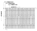
次に、上記ドットパターン形成部106の構成および動作について図6〜図9を参照しながら説明する。図6は図4のドットパターン形成部106の構成を示すブロック図である。図7は図6のドットパターン形成部106の動作を示すタイミングチャートである。図8はLMのドットパターンの一部領域におけるドットトナー像の形成位置を模式的に示す図である。図9はLM,LC,Yの各色のドットパターンが重ね合わされた領域の一部を模式的に示す図である。
Next, the configuration and operation of the dot
ドットパターン形成部106は、図6に示すように、複数のカウンタ回路201,202,203およびLUT(Look Up Table)回路204から構成される。このドットパターン形成部106は、用紙エリアを矩形状の複数のドット領域に分割する。そして、ドットパターン形成部106は、各ドット領域内に各色(LM,LC,Y)の少なくとも1つのドットナー像を形成することにより、ドットトナー像が分散された各色(LM,LC,Y)のドットパターンを形成する。本実施の形態においては、用紙エリアが、8ドット×6ドットからなる複数のドット領域に分割され、各ドット領域内に各色(LM,LC,Y)の1つのドットトナー像がそれぞれ形成される。
As shown in FIG. 6, the dot
カウンタ回路201は、用紙エリアを主走査方向Xに沿って複数のドット領域に分割するために、画像クロックをクロック入力とし、「0」から「7」までのカウントを繰り返すカウンタである。カウンタ回路201には、用紙エリアの主走査方向Xの先端位置を示す初期値が、主走査トップ信号(主走査ドットパターンエリア信号またはそれに同期する信号)の入力に応答して取り込まれる。ここでは、上記初期値としては、カウンタ回路203の出力が取り込まれる。カウンタ回路201は、まず、取り込まれた初期値から「7」までをカウントを行う。その後、「0」から「7」までのカウントが、主走査方向Xの位置がドットパターンの主走査方向の後端位置に達するまで、繰り返される。
The
カウンタ回路202は、上記主走査トップ信号をクロックとして、副走査方向に対して0から5のカウントを繰り返すカウンタであり、そのカウント値は、副走査トップ信号の入力によりリセットされる。すなわち、カウンタ回路201による主走査方向のカウントが一回終了したときに「1」カウントアップする。
The
カウンタ回路203は、ドット領域を副走査方向へシフトする際のカウンタ回路201の初期値を設定するためのカウンタである。カウンタ回路203は、主走査トップ信号をクロック入力とし、カウンタ回路202が「0」から「5」までカウントして再び「0」に戻るとき、すなわちカウンタ回路202がオーバフローする度に1インクリメントする。そして、カウンタ回路203は、上記主走査トップ信号が入力されると、そのときのカウント値をカウンタ回路201へ出力する。すなわち、カウンタ回路202による「0」から「5」までの繰り返しカウント回数が6回に達すると、ドット領域を副走査方向へシフトするために、カウンタ回路203のカウント値が「1」インクリメントする。
The
LUT回路204には、カウンタ回路201から出力されたカウント値とカウンタ回路202から出力されたカウント値とが入力される。また、LUT回路204には、LM,LC,Yの各色のドットパターンにおけるドットトナー像の形成位置を規定するためのテーブルが保持されている。LUT回路204は、上記テーブルを参照して、上記テーブル中の対応する値と一致するLM,LC,Yの色毎に入力された各カウント値の組み合わせ(X,Y)をドットトナー像の形成位置とし、「0」のドットパターン信号を出力する。本実施の形態においては、LMのドットパターンに対しては、(X,Y)=(3,0)がドットトナー像の形成位置として設定される。また、LCのドットパターンに対しては、(X,Y)=(1,4)が、Yのドットパターンに対しては、(X,Y)=(5,3)がドットトナー像の形成位置として設定される。これにより、各色のドットトナー像は、互いに重ならない位置に形成されることになる。
The count value output from the
このように構成されたドットパターン形成部106の動作について図7および図8を参照しながら説明する。ここでは、LMのドットパターンを形成する場合を説明する。
The operation of the dot
ドットパターンの形成開始時、図7に示すように、副走査トップ信号がカウンタ回路202およびカウンタ回路203へ入力される。また、主走査トップ信号がカウンタ回路202およびカウンタ回路203に対してクロック入力として入力され、またカウンタ回路201に対してロード入力として入力される。
At the start of dot pattern formation, the sub-scanning top signal is input to the
カウンタ回路202は、副走査トップ信号の入力に応じてリセットされ、主走査トップ信号をクロック入力として、「0」〜「5」までのカウントを開始する。カウンタ203回路は、副走査トップ信号の入力に応じてリセットされ、主走査トップ信号をクロック入力として、「0」のカウント値を保持する。このカウンタ回路202の出力は、LUT回路204へ出力される。
The
カウンタ回路201は、主走査トップ信号が入力されると、カウンタ回路203のカウント値を初期値として取り込み、画像クロックをクロック入力として、カウント動作を開始する。ここで、ドットパターンの形成開始時時には、カウンタ回路203のカウント値は「0」であるので、カウンタ回路201には、初期値として「0」が取り込まれる。よって、カウンタ回路201は、まず初期値として取り込まれた「0」から「7」までのカウント動作を行い、以降「0」から「7」までのカウントを繰り返し行う。カウンタ回路201のカウント値は、LUT回路204へ出力される。
When the main scanning top signal is input, the
LUT回路204は、上記テーブルを参照して、LMに対して設定されている数値の組み合わせに一致するカウンタ回路201のカウント値Xとカウンタ回路202のカウント値Yが入力されると、値が「1」であるドットパターン信号を出力する。ここでは、上述したように、(X,Y)=(3,0)の関係式が満足されると、上記ドットパターン信号が出力される。上記関係式を満足しない場合、値が「0」であるドットパターン信号が出力される。
The
そして、カウンタ回路202が「5」までのカウントが終了するすなわちオーバフローするまで、上述したような各カウンタ回路201,202,203のカウント動作が行われるとともに、LUT回路204の動作が行われる。
Then, until the
カウンタ回路202がオーバフローすると、オーバフロー信号がカウンタ回路203へ出力される。カウンタ回路203は、上記オーバフロー信号により、カウント値を1インクリメントする。すなわち、カウンタ回路203は、カウント値を「0」から「1」へインクリメントし、このカウント値「1」を保持する。
When the
ここで、上記カウンタ回路202がオーバフローしたことは、カウンタ回路201に対して、主走査トップ信号が6回入力されたことになる。すなわち、1回目の主走査方向へのドット領域の分割が終了し、副走査方向へドット領域のシフトが行われることになる。そして、カウンタ回路201には、7回目の主走査トップ信号の入力により、カウンタ回路203が保持するカウント値すなわち「1」が初期値として取り込まれ、カウンタ回路201は、上記初期値「1」から「7」までのカウントを行う。これ以降、カウンタ回路201は、「0」から「7」までのカウントを繰り返し行う。このカウンタ回路201に対する上記初期値の設定により、ドット領域におけるドットトナー像の形成位置が、主走査方向Xと反対方向へ1ドット分シフトされる。
Here, the overflow of the
このようにしてドット領域が副走査方向へシフトされる度に、ドット領域におけるドットトナー像の形成位置が、主走査方向Xと反対方向へ1ドットずつシフトされ、それぞれの形成位置は、副走査方向に関して、同一直線上に並ばないように分散される。これによって、例えば図8に示すように、ドットトナー像の形成位置(斜線部分)が分散され、それぞれの形成位置にLMのドットトナー像が形成されることになる。 Each time the dot area is shifted in the sub-scanning direction in this way, the dot toner image formation position in the dot area is shifted one dot at a time in the direction opposite to the main scanning direction X. The direction is distributed so as not to be aligned on the same straight line. As a result, for example, as shown in FIG. 8, the dot toner image forming positions (shaded portions) are dispersed, and LM dot toner images are formed at the respective forming positions.
これにより、副走査方向に関してドットトナー像が同一直線上に並ぶと、用紙上に転写された各ドットトナー像が目立つ、という不具合が回避される。また、二次転写ローラ54の表面に縦スジ汚れが発生すること、クリーニング装置6の特定位置にトナーが過度に溜まることなどが未然に防止される。
Thereby, when the dot toner images are arranged on the same straight line in the sub-scanning direction, the problem that the dot toner images transferred onto the paper stand out is avoided. Further, it is possible to prevent the occurrence of vertical streak stains on the surface of the
本実施の形態においては、ドット領域が副走査方向へシフトされる度にドットトナー像の形成位置が1ドット分シフトされているが、シフトするドット数はこれに限定されるものではない。例えばドット領域の主走査方向サイズmが8ドットの場合において、シフトするドット数をkとすると、主走査方向サイズm(8)との最大公約数が1となるような値例えば3,5,7を、ドット数kとすることも可能である。この場合も同様に、ドットトナー像の形成位置は、副走査方向に関して、同一直線上に並ばないように分散される。 In the present embodiment, the dot toner image formation position is shifted by one dot each time the dot area is shifted in the sub-scanning direction, but the number of dots to be shifted is not limited to this. For example, in the case where the main scanning direction size m of the dot region is 8 dots, a value such that the greatest common divisor with respect to the main scanning direction size m (8) is 1 when the number of dots to be shifted is k, for example 3, 5, 7 may be the number of dots k. In this case as well, the dot toner image formation positions are dispersed so as not to be aligned on the same straight line in the sub-scanning direction.
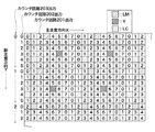
また、LMのドットトナー像と同様に、LC,Yのドットトナー像も、LUT回路204のテーブルに記述された値に応じた位置に形成される。このようにして、LM,LC,Yの各色のドットトナー像が形成されると、図9に示すようなドットパターンが得られることになる。
Similarly to the LM dot toner image, the LC and Y dot toner images are also formed at positions corresponding to the values described in the table of the
また、ドットパターンは、上述したようなパターンに限定されるものではなく、通常画像の種類、その他の条件などによって、各色のドットトナー像の形成位置を変更するようにしてもよい。この場合は、各カウンタ回路のカウント数の変更、LUT回路のテーブルから対応する値を選択することによって、実現することが可能である。また、ドットトナー像の形成位置を決定するための構成は、上述したドットパターン形成部の構成に限定されるものではない。 Further, the dot pattern is not limited to the pattern as described above, and the formation position of the dot toner image of each color may be changed depending on the type of the normal image, other conditions, and the like. This case can be realized by changing the count number of each counter circuit and selecting a corresponding value from the table of the LUT circuit. Further, the configuration for determining the dot toner image formation position is not limited to the configuration of the dot pattern forming unit described above.
また、本実施の形態においては、用紙エリア全体に拡がるドットパターンを形成するようにしているが、これに代えて、ドットパターンを、用紙エリアにおいて、その先端から画像エリアまでの領域に形成するようにしてもよい。 In this embodiment, a dot pattern that extends over the entire paper area is formed. Instead, a dot pattern is formed in the area from the leading edge to the image area in the paper area. It may be.
感光ドラム1と中間転写ベルト52との間の摩擦力の変化によって生じる画像スジは、カラー画像形成時のみに限らず、例えばK(ブラック)単色の画像形成を行う場合にも発生するため、モノクロ画像形成時にも、高品質の画像形成を行うことができる。
Image streaks caused by a change in frictional force between the
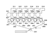
また、本発明の原理は、例えば図10に示すようなタンデム型の画像形成装置にも適用することもできる。このタンデム型画像形成装置は、LM,LC,Y,M,C,Kのトナー像をそれぞれ形成するための複数の画像形成ステーションを有する。各画像形成ステーションは、感光ドラム301〜306、露光装置311〜316、現像器321〜326、トナー収納部331〜336、および一次転写器341〜346を有する。各画像形成ステーションの感光ドラム301〜306のそれぞれにより形成されたトナー像は、対応する一次転写器341〜346により、中間転写ベルト350上に順に重ね合わされて転写される(一次転写)。これにより、中間転写ベルト350上には、フルカラートナー像が形成される。
The principle of the present invention can also be applied to a tandem type image forming apparatus as shown in FIG. This tandem type image forming apparatus has a plurality of image forming stations for forming LM, LC, Y, M, C, and K toner images, respectively. Each image forming station includes
中間転写ベルト350上に形成されたフルカラートナー像は、二次転写ローラ351により、給紙された用紙上に転写される(二次転写)。フルカラートナー像が転写された用紙は、定着器(図示せず)に送られ、用紙上のフルカラートナー像は、熱圧されて用紙上に定着される。そして、この用紙は、機外へ排出される。
The full-color toner image formed on the
また、感光ドラムに形成されたトナー像を、用紙搬送体に担持された用紙上に重ねて転写する画像形成装置において、感光ドラムと用紙搬送体とが、それらの間に周速差が生じるように駆動される場合も、本発明の原理を適用することができる。 Further, in the image forming apparatus for transferring the toner image formed on the photosensitive drum on the sheet carried on the sheet conveyance body, a circumferential speed difference is generated between the photosensitive drum and the sheet conveyance body. The principle of the present invention can also be applied to the case of driving.
また、感光ドラムと転写体との間の周速差がない構成においても、駆動ローラの偏芯などにより意図しない速度差が発生する場合がある。このような場合も、感光ドラムと転写体との間の周速差がある場合と同様に、画像スジが発生することがあるので、感光ドラムと転写体との間の周速差がない構成に対しても、本発明の原理を適用することができる。 Even in a configuration in which there is no peripheral speed difference between the photosensitive drum and the transfer body, an unintended speed difference may occur due to eccentricity of the drive roller. In such a case, as in the case where there is a peripheral speed difference between the photosensitive drum and the transfer body, image streaks may occur, so there is no peripheral speed difference between the photosensitive drum and the transfer body. Also, the principle of the present invention can be applied.
1 感光ドラム
1P プリンタ部
3 露光装置
41〜46 現像器
52 中間転写ベルト
53 一次転写ローラ
54 二次転写ローラ
103 画像処理部
104 論理和回路
105 レーザユニット
106 ドットパターン形成部
107 PWM回路
DESCRIPTION OF
Claims (5)
入力画像データから前記複数色のトナーの画像データを生成する画像処理手段と、
ドットが分散されて配置されている前記第2トナーのドットパターンを作成するドットパターン作成部と、
前記画像データと前記第2トナーのドットパターンを合成し、出力画像データを出力する合成手段と、
前記複数色のトナーを用いて、前記出力画像データに基づき像担持体上にトナー像を形成する画像形成手段と、
前記像担持体上に形成されたトナー像を転写体に転写する転写手段と、
を有することを特徴とする画像形成装置。 An image forming apparatus for forming an image using a plurality of color toners including a second toner having the same hue as the first toner and the first toner and having a lightness higher than that of the first toner ,
Image processing means for generating image data of the plurality of color toners from input image data ;
A dot pattern creating unit that creates a dot pattern of the second toner in which dots are dispersed; and
A combining means for combining the image data and the dot pattern of the second toner and outputting output image data;
An image forming means for forming a toner image on an image carrier based on the output image data using the plurality of color toners;
Transfer means for transferring the toner image formed on the image carrier to a transfer member;
An image forming apparatus characterized by have a.
前記ドットパターン作成部は、前記淡いマゼンタ及び前記淡いシアンに加えて前記イエローを用いて前記ドットパターンを作成することを特徴とする請求項1又は2記載の画像形成装置。 The multi-color toners are yellow, magenta, cyan black, light magenta and light cyan ,
The dot pattern creation section, an image forming apparatus according to claim 1, wherein that you create the dot pattern using the yellow in addition to the light magenta and the light cyan.
Priority Applications (2)
| Application Number | Priority Date | Filing Date | Title |
|---|---|---|---|
| JP2006163862A JP4939119B2 (en) | 2006-06-13 | 2006-06-13 | Image forming apparatus |
| US11/762,345 US7796150B2 (en) | 2006-06-13 | 2007-06-13 | Image forming apparatus with multi-color dot image formation |
Applications Claiming Priority (1)
| Application Number | Priority Date | Filing Date | Title |
|---|---|---|---|
| JP2006163862A JP4939119B2 (en) | 2006-06-13 | 2006-06-13 | Image forming apparatus |
Publications (3)
| Publication Number | Publication Date |
|---|---|
| JP2007333889A JP2007333889A (en) | 2007-12-27 |
| JP2007333889A5 JP2007333889A5 (en) | 2009-07-23 |
| JP4939119B2 true JP4939119B2 (en) | 2012-05-23 |
Family
ID=38821473
Family Applications (1)
| Application Number | Title | Priority Date | Filing Date |
|---|---|---|---|
| JP2006163862A Expired - Fee Related JP4939119B2 (en) | 2006-06-13 | 2006-06-13 | Image forming apparatus |
Country Status (2)
| Country | Link |
|---|---|
| US (1) | US7796150B2 (en) |
| JP (1) | JP4939119B2 (en) |
Families Citing this family (4)
| Publication number | Priority date | Publication date | Assignee | Title |
|---|---|---|---|---|
| US7773897B2 (en) * | 2006-12-01 | 2010-08-10 | Canon Kabushiki Kaisha | Image forming apparatus and control method thereof |
| JP5041583B2 (en) * | 2006-12-21 | 2012-10-03 | キヤノン株式会社 | Scanning optical apparatus and image forming apparatus |
| JP2012103440A (en) * | 2010-11-09 | 2012-05-31 | Canon Inc | Image forming device and image forming method |
| JP2016086254A (en) * | 2014-10-24 | 2016-05-19 | キヤノン株式会社 | Image forming apparatus |
Family Cites Families (7)
| Publication number | Priority date | Publication date | Assignee | Title |
|---|---|---|---|---|
| JP3963534B2 (en) | 1997-08-02 | 2007-08-22 | 株式会社リコー | Image forming apparatus |
| JP4378026B2 (en) * | 1999-04-02 | 2009-12-02 | キヤノン株式会社 | Image forming apparatus and image forming method |
| JP2004118076A (en) * | 2002-09-27 | 2004-04-15 | Canon Inc | Image forming apparatus |
| JP4261873B2 (en) * | 2002-10-31 | 2009-04-30 | キヤノン株式会社 | Image forming apparatus |
| US20050219623A1 (en) * | 2003-07-23 | 2005-10-06 | Konica Minolta Holdings, Inc. | Image processing apparatus and image processing method |
| JP2005341142A (en) * | 2004-05-26 | 2005-12-08 | Seiko Epson Corp | Image processor, processing method and program, and recording medium with the program stored |
| US7603064B2 (en) * | 2004-09-07 | 2009-10-13 | Canon Kabushiki Kaisha | Unit for tone-processing image data using screen pattern with different screen angles for toners of same hue and different density |
-
2006
- 2006-06-13 JP JP2006163862A patent/JP4939119B2/en not_active Expired - Fee Related
-
2007
- 2007-06-13 US US11/762,345 patent/US7796150B2/en not_active Expired - Fee Related
Also Published As
| Publication number | Publication date |
|---|---|
| JP2007333889A (en) | 2007-12-27 |
| US20070285490A1 (en) | 2007-12-13 |
| US7796150B2 (en) | 2010-09-14 |
Similar Documents
| Publication | Publication Date | Title |
|---|---|---|
| JP4981265B2 (en) | Image forming apparatus | |
| JP4859444B2 (en) | Image forming apparatus | |
| JP2005161650A (en) | Imaging device, pattern forming method and program | |
| JP2010231056A (en) | Image forming apparatus | |
| JP2006212894A (en) | Image forming apparatus | |
| JP2009163103A (en) | Image forming device and image forming method | |
| JP4105168B2 (en) | Image forming apparatus | |
| JP4939119B2 (en) | Image forming apparatus | |
| JP2013020076A (en) | Image forming apparatus, calculating method of toner consumption, and computer program | |
| US7773897B2 (en) | Image forming apparatus and control method thereof | |
| JP2006195246A (en) | Image forming apparatus | |
| JP2004151588A (en) | Image forming apparatus | |
| JP4040632B2 (en) | Image forming apparatus | |
| JP2012103317A (en) | Image forming device | |
| JP5699534B2 (en) | Image forming apparatus | |
| JP5817269B2 (en) | Image forming apparatus, toner consumption calculation method, and computer program | |
| JP2006020181A (en) | Image processor, image forming apparatus, image forming method and program therefor | |
| JP2016109752A (en) | Image formation apparatus | |
| JP6589596B2 (en) | Image forming apparatus and image forming method | |
| JP5751009B2 (en) | Image forming apparatus, image forming method, and computer program | |
| JP4019626B2 (en) | Image forming apparatus | |
| JP2010145682A (en) | Image forming apparatus, image formation control method, and program executable on computer | |
| JP2008049694A (en) | Imaging device/method | |
| JP2024009480A (en) | Image forming device | |
| JP2005165229A (en) | Electrophotographic type image forming apparatus and method |
Legal Events
| Date | Code | Title | Description |
|---|---|---|---|
| A521 | Request for written amendment filed |
Free format text: JAPANESE INTERMEDIATE CODE: A523 Effective date: 20090608 |
|
| A621 | Written request for application examination |
Free format text: JAPANESE INTERMEDIATE CODE: A621 Effective date: 20090608 |
|
| A131 | Notification of reasons for refusal |
Free format text: JAPANESE INTERMEDIATE CODE: A131 Effective date: 20110726 |
|
| A977 | Report on retrieval |
Free format text: JAPANESE INTERMEDIATE CODE: A971007 Effective date: 20110727 |
|
| A521 | Request for written amendment filed |
Free format text: JAPANESE INTERMEDIATE CODE: A523 Effective date: 20110822 |
|
| TRDD | Decision of grant or rejection written | ||
| A01 | Written decision to grant a patent or to grant a registration (utility model) |
Free format text: JAPANESE INTERMEDIATE CODE: A01 Effective date: 20120221 |
|
| A01 | Written decision to grant a patent or to grant a registration (utility model) |
Free format text: JAPANESE INTERMEDIATE CODE: A01 |
|
| A61 | First payment of annual fees (during grant procedure) |
Free format text: JAPANESE INTERMEDIATE CODE: A61 Effective date: 20120224 |
|
| FPAY | Renewal fee payment (event date is renewal date of database) |
Free format text: PAYMENT UNTIL: 20150302 Year of fee payment: 3 |
|
| FPAY | Renewal fee payment (event date is renewal date of database) |
Free format text: PAYMENT UNTIL: 20150302 Year of fee payment: 3 |
|
| LAPS | Cancellation because of no payment of annual fees |