JP4932715B2 - Intramedullary rod with spiral flutes - Google Patents
Intramedullary rod with spiral flutes Download PDFInfo
- Publication number
- JP4932715B2 JP4932715B2 JP2007527739A JP2007527739A JP4932715B2 JP 4932715 B2 JP4932715 B2 JP 4932715B2 JP 2007527739 A JP2007527739 A JP 2007527739A JP 2007527739 A JP2007527739 A JP 2007527739A JP 4932715 B2 JP4932715 B2 JP 4932715B2
- Authority
- JP
- Japan
- Prior art keywords
- rod
- longitudinal axis
- plane
- curvature
- longitudinal
- Prior art date
- Legal status (The legal status is an assumption and is not a legal conclusion. Google has not performed a legal analysis and makes no representation as to the accuracy of the status listed.)
- Active
Links
- 210000000988 bone and bone Anatomy 0.000 claims description 48
- 208000010392 Bone Fractures Diseases 0.000 claims description 13
- 210000001185 bone marrow Anatomy 0.000 claims 1
- 238000003780 insertion Methods 0.000 abstract description 30
- 230000037431 insertion Effects 0.000 abstract description 30
- 206010017076 Fracture Diseases 0.000 description 23
- 210000000689 upper leg Anatomy 0.000 description 23
- 210000002320 radius Anatomy 0.000 description 12
- 238000000034 method Methods 0.000 description 7
- 238000005452 bending Methods 0.000 description 5
- 210000002436 femur neck Anatomy 0.000 description 4
- 238000004873 anchoring Methods 0.000 description 3
- 238000013461 design Methods 0.000 description 3
- 210000000527 greater trochanter Anatomy 0.000 description 3
- 230000009467 reduction Effects 0.000 description 3
- 238000002627 tracheal intubation Methods 0.000 description 3
- RTAQQCXQSZGOHL-UHFFFAOYSA-N Titanium Chemical compound [Ti] RTAQQCXQSZGOHL-UHFFFAOYSA-N 0.000 description 2
- 230000002411 adverse Effects 0.000 description 2
- 230000008468 bone growth Effects 0.000 description 2
- 210000002758 humerus Anatomy 0.000 description 2
- 230000000642 iatrogenic effect Effects 0.000 description 2
- 210000000528 lesser trochanter Anatomy 0.000 description 2
- 230000033001 locomotion Effects 0.000 description 2
- 239000002184 metal Substances 0.000 description 2
- 229910052751 metal Inorganic materials 0.000 description 2
- 238000012986 modification Methods 0.000 description 2
- 230000004048 modification Effects 0.000 description 2
- 230000008569 process Effects 0.000 description 2
- 210000002303 tibia Anatomy 0.000 description 2
- 239000010936 titanium Substances 0.000 description 2
- 229910052719 titanium Inorganic materials 0.000 description 2
- 210000000623 ulna Anatomy 0.000 description 2
- 229910001069 Ti alloy Inorganic materials 0.000 description 1
- 238000013459 approach Methods 0.000 description 1
- 238000010276 construction Methods 0.000 description 1
- 230000001054 cortical effect Effects 0.000 description 1
- 230000003111 delayed effect Effects 0.000 description 1
- 210000003275 diaphysis Anatomy 0.000 description 1
- 230000000694 effects Effects 0.000 description 1
- 208000020089 femoral neck fracture Diseases 0.000 description 1
- 239000012634 fragment Substances 0.000 description 1
- 230000035876 healing Effects 0.000 description 1
- 230000001939 inductive effect Effects 0.000 description 1
- 230000009545 invasion Effects 0.000 description 1
- 239000000463 material Substances 0.000 description 1
- 229910001092 metal group alloy Inorganic materials 0.000 description 1
- 239000007769 metal material Substances 0.000 description 1
- 238000003801 milling Methods 0.000 description 1
- 238000012544 monitoring process Methods 0.000 description 1
- 239000010935 stainless steel Substances 0.000 description 1
- 229910001220 stainless steel Inorganic materials 0.000 description 1
- 230000007704 transition Effects 0.000 description 1
- 230000002792 vascular Effects 0.000 description 1
Images


Classifications
-
- A—HUMAN NECESSITIES
- A61—MEDICAL OR VETERINARY SCIENCE; HYGIENE
- A61B—DIAGNOSIS; SURGERY; IDENTIFICATION
- A61B17/00—Surgical instruments, devices or methods, e.g. tourniquets
- A61B17/56—Surgical instruments or methods for treatment of bones or joints; Devices specially adapted therefor
- A61B17/58—Surgical instruments or methods for treatment of bones or joints; Devices specially adapted therefor for osteosynthesis, e.g. bone plates, screws, setting implements or the like
- A61B17/68—Internal fixation devices, including fasteners and spinal fixators, even if a part thereof projects from the skin
- A61B17/72—Intramedullary pins, nails or other devices
- A61B17/7283—Intramedullary pins, nails or other devices with special cross-section of the nail
-
- A—HUMAN NECESSITIES
- A61—MEDICAL OR VETERINARY SCIENCE; HYGIENE
- A61B—DIAGNOSIS; SURGERY; IDENTIFICATION
- A61B17/00—Surgical instruments, devices or methods, e.g. tourniquets
- A61B17/56—Surgical instruments or methods for treatment of bones or joints; Devices specially adapted therefor
- A61B17/58—Surgical instruments or methods for treatment of bones or joints; Devices specially adapted therefor for osteosynthesis, e.g. bone plates, screws, setting implements or the like
- A61B17/68—Internal fixation devices, including fasteners and spinal fixators, even if a part thereof projects from the skin
- A61B17/72—Intramedullary pins, nails or other devices
- A61B17/7233—Intramedullary pins, nails or other devices with special means of locking the nail to the bone
- A61B17/7241—Intramedullary pins, nails or other devices with special means of locking the nail to the bone the nail having separate elements through which screws pass
-
- A—HUMAN NECESSITIES
- A61—MEDICAL OR VETERINARY SCIENCE; HYGIENE
- A61B—DIAGNOSIS; SURGERY; IDENTIFICATION
- A61B17/00—Surgical instruments, devices or methods, e.g. tourniquets
- A61B17/56—Surgical instruments or methods for treatment of bones or joints; Devices specially adapted therefor
- A61B17/58—Surgical instruments or methods for treatment of bones or joints; Devices specially adapted therefor for osteosynthesis, e.g. bone plates, screws, setting implements or the like
- A61B17/68—Internal fixation devices, including fasteners and spinal fixators, even if a part thereof projects from the skin
- A61B17/74—Devices for the head or neck or trochanter of the femur
- A61B17/742—Devices for the head or neck or trochanter of the femur having one or more longitudinal elements oriented along or parallel to the axis of the neck
- A61B17/744—Devices for the head or neck or trochanter of the femur having one or more longitudinal elements oriented along or parallel to the axis of the neck the longitudinal elements coupled to an intramedullary nail
-
- A—HUMAN NECESSITIES
- A61—MEDICAL OR VETERINARY SCIENCE; HYGIENE
- A61B—DIAGNOSIS; SURGERY; IDENTIFICATION
- A61B17/00—Surgical instruments, devices or methods, e.g. tourniquets
- A61B17/56—Surgical instruments or methods for treatment of bones or joints; Devices specially adapted therefor
- A61B17/58—Surgical instruments or methods for treatment of bones or joints; Devices specially adapted therefor for osteosynthesis, e.g. bone plates, screws, setting implements or the like
- A61B17/68—Internal fixation devices, including fasteners and spinal fixators, even if a part thereof projects from the skin
- A61B17/72—Intramedullary pins, nails or other devices
- A61B17/7233—Intramedullary pins, nails or other devices with special means of locking the nail to the bone
Landscapes
- Health & Medical Sciences (AREA)
- Orthopedic Medicine & Surgery (AREA)
- Surgery (AREA)
- Life Sciences & Earth Sciences (AREA)
- Molecular Biology (AREA)
- Public Health (AREA)
- Engineering & Computer Science (AREA)
- Biomedical Technology (AREA)
- Heart & Thoracic Surgery (AREA)
- Medical Informatics (AREA)
- Neurology (AREA)
- Animal Behavior & Ethology (AREA)
- General Health & Medical Sciences (AREA)
- Nuclear Medicine, Radiotherapy & Molecular Imaging (AREA)
- Veterinary Medicine (AREA)
- Surgical Instruments (AREA)
- Prostheses (AREA)
- Piles And Underground Anchors (AREA)
- Paper (AREA)
- Laying Of Electric Cables Or Lines Outside (AREA)
- Fixing For Electrophotography (AREA)
- Reinforcement Elements For Buildings (AREA)
Abstract
Description
本発明は、一般的に骨折の内部固定のためのシステムに関し、特に、例えば長骨骨折の治療に用いられるような骨髄内骨折固定装置に関する。 The present invention relates generally to systems for internal fixation of fractures, and more particularly to intramedullary fracture fixation devices such as those used in the treatment of long bone fractures.
大腿のような長骨の骨折は、患部の骨の随管に挿入される骨髄内ロッド(IMロッド)を用いて治療されることが多い。当業技術で公知のように、IMロッドは、一般的に、螺旋ブレードを有するくぎ固定装置を含むネジ又はくぎのような関連の横材と共に細長いロッドを含む。IMロッドは、典型的に、破砕された骨セグメントを安定化させて互いに保持するためにIMロッドを通して骨組織内へこれらの関連の横材を配置することを考慮した様々な横孔を含む。例えば、大腿骨頚及び/又は大腿骨頭の領域の骨折の治療において、横材は、IMロッドの近位部分を通して挿入し、骨折部を横断し、次に大腿骨頭内に入れることができる。より遠位の骨幹型の骨折では、止めネジをIMロッドを通して適正な形状で骨組織内に配置し、骨セグメントの固定をもたらすことができる。 Long bone fractures such as the thigh are often treated with intramedullary rods (IM rods) inserted into the canal of the affected bone. As is known in the art, IM rods generally include an elongated rod with an associated cross member such as a screw or nail that includes a nail fixation device having a helical blade. IM rods typically include various lateral holes that allow for the placement of these associated cross members through the IM rod and into bone tissue to stabilize and hold the fractured bone segments together. For example, in the treatment of fractures in the femoral neck and / or femoral head region, the crosspiece can be inserted through the proximal portion of the IM rod, traversed the fracture, and then into the femoral head. For more distal diaphyseal fractures, a set screw can be placed in the bone tissue in the proper shape through the IM rod, resulting in fixation of the bone segment.
骨髄内ロッドを移植する技術は、髄管の中心線の側方にある点、すなわち、梨状陥凹からオフセットした点を通るロッドの挿入を伴う。この技術を使用する多くの実施例の1つは、Zickelに付与された米国特許第3,433,220号に示されている。転子の先端での骨切術が行われて侵入部位が作られ、可撓性リーマを使用して、その基本骨格に適合させながら髄管の拡孔を実行する。侵入部位の位置が髄管の軸線から横方向にオフセットしているので、侵入部位と髄管の間に傾斜した又は湾曲した開口部が作成される。 The technique of implanting an intramedullary rod involves the insertion of the rod through a point that is lateral to the center line of the medullary canal, that is, a point that is offset from the piriform depression. One of many examples using this technique is shown in US Pat. No. 3,433,220 to Zickel. Osteotomy at the tip of the trochanter is performed to create an invasion site, and a flexible reamer is used to perform medullary canal expansion while adapting to its basic skeleton. Since the location of the entry site is offset laterally from the axis of the medullary canal, an inclined or curved opening is created between the entry site and the medullary canal.
開口部が作られた状態で、IMロッドは、侵入部位を通って髄管内に挿入することができる。しかし、横方向オフセット配置におけるIMロッドの挿入点は、開口部の髄管内への湾曲が大腿の髄管内にロッドを「曲げる」ので、医原性骨折の可能な部位である。これは、骨に対する横方向点荷重の不慮の印加による骨折の可能性を引き起こす。骨折は、侵入部位に始まり、IMロッド挿入に従って転子間領域を通って延びることが観察されている。 With the opening made, the IM rod can be inserted through the entry site and into the medullary canal. However, the point of insertion of the IM rod in the lateral offset configuration is a possible site for iatrogenic fractures because the curvature of the opening into the medullary canal “bends” the rod into the medullary canal of the femur. This causes the possibility of fractures due to inadvertent application of lateral point loads on the bone. Fractures have been observed to begin at the site of entry and extend through the intertrochanteric region following IM rod insertion.
更に、大腿自体の髄管の形状が、IMロッドの挿入を困難にする可能性がある。髄管は、その長さにわたって緩く、均一に、前方に湾曲している。IMロッドが前方への曲げ又は湾曲を有していなければ、横方向点荷重が大腿の皮質壁に作用して骨折に至る場合がある。髄管の過度の拡孔は、挿入中の骨幹の破砕を防ぐことができるが、これは、ロッドと骨の間の接触表面積の低減をもたらし、骨片の固定の有効性を弱めることになる。過度の拡孔の別の悪影響は、骨の曲げ及び捩れ強さの低減である。その結果、Zickelに付与された米国特許第3,433,220号及びHarrisに付与された米国特許第4,135,507号のような特許によって従来技術で例示されているように、多くのIMロッドは、大腿の通常の髄構造に適合させるために、前部−後部平面において前方の曲げ又は湾曲を有する。 Furthermore, the shape of the medullary canal of the thigh itself can make it difficult to insert an IM rod. The medullary canal is loose and uniformly curved forward over its length. If the IM rod does not have a forward bend or curvature, a lateral point load may act on the cortical wall of the thigh leading to a fracture. Excessive enlargement of the medullary canal prevents fracture of the diaphysis during insertion, but this leads to a reduction in the surface area of contact between the rod and the bone and weakens the effectiveness of bone fragment fixation . Another adverse effect of excessive hole expansion is a reduction in bone bending and torsional strength. As a result, as illustrated in the prior art by patents such as US Pat. No. 3,433,220 to Zickel and US Pat. No. 4,135,507 to Harris, many IMs The rod has an anterior bend or curvature in the anterior-posterior plane to conform to the normal medullary structure of the thigh.
しかし、前部−後部平面におけるロッドの湾曲だけでは、横方向にオフセットされた侵入部位を通るIMロッドの挿入から発生する困難を必ずしも克服しない。ロッドの前部湾曲が、侵入部位と髄管の間の開口部の湾曲に対して直角面にあるので、ロッドがその最終位置にある状態で、IMロッドの近位セグメントによって付加的な側面点荷重を骨に掛ける場合がある。これはまた、大腿の次の骨折をもたらす場合がある。その結果、一部のIMロッド(従来技術のZickel及びHarrisの特許に開示するような)は、侵入点から髄管内への開口部に適合するように試みる横−内側平面における曲げ又は湾曲を組み込んでいる。それにも関わらず、これらの横方向に湾曲したロッドは、挿入又は除去処置中の不慮の骨折の解消に完全には成功していない。 However, the curvature of the rod in the front-rear plane alone does not necessarily overcome the difficulties arising from the insertion of the IM rod through the laterally offset entry site. Since the anterior curvature of the rod is at a right angle to the curvature of the opening between the entry site and the medullary canal, an additional lateral point is provided by the proximal segment of the IM rod with the rod in its final position. A load may be placed on the bone. This may also result in the next fracture of the thigh. As a result, some IM rods (as disclosed in prior art Zickel and Harris patents) incorporate bending or bending in the transverse-inner plane that attempts to fit the opening from the entry point into the medullary canal. It is out. Nevertheless, these laterally curved rods have not been fully successful in resolving accidental fractures during the insertion or removal procedure.
IMロッドに前部湾曲が備わっていると、挿入前にその縦軸線回りに約90度ロッドを回転することは、ロッドの湾曲が侵入部位と髄管の間の開口部の湾曲をより正確に近似することができると考えられるので、髄管内へのその挿入を容易にする場合がある。すなわち、ロッドは、最初にこの回転した向きに挿入され、次に、それがその最終位置まで髄管内を駆動される時に捩られる。しかし、適時に適正な量の捩り力を印加することには問題があり、その理由は、髄管内へのロッドの進行の正確な程度を継続してモニタする一方で、各点で要求される対応する量の捩りも印加することが困難であると考えられるからである。更に、IMロッドには、多くの場合に、挿入中にこの捩り運動を妨げる場合があるロッドのシャフトの表面を真っ直ぐ下方に延びる外部縦溝が設けられている。これらの外部縦溝は、脊髄血管再開通術の改善、より大きな強度を伴う剛性の低減、及びロッド−骨インタフェースでの捩り固定の改善のような恩典をもたらすので望ましいが、髄管内での骨と縦溝の係合は、ロッドを挿入するために必要な捩りを実際に妨げる場合がある。 If the IM rod has an anterior curvature, rotating the rod about 90 degrees about its longitudinal axis before insertion will make the curvature of the rod more accurately the curvature of the opening between the entry site and the medullary canal. Since it can be approximated, it may facilitate its insertion into the medullary canal. That is, the rod is first inserted in this rotated orientation and then twisted as it is driven through the medullary canal to its final position. However, applying the right amount of torsional force in a timely manner is problematic because it is required at each point while continuously monitoring the exact extent of rod progression into the medullary canal. This is because it is considered difficult to apply a corresponding amount of torsion. In addition, IM rods are provided with external flutes that extend straight down the surface of the rod shaft, which in many cases may prevent this torsional motion during insertion. These external flutes are desirable because they provide benefits such as improved spinal vascular reopening, reduced stiffness with greater strength, and improved torsional fixation at the rod-bone interface, but bone within the medullary canal And the engagement of the flutes may actually hinder the torsion necessary to insert the rod.
本発明のIMロッドは、好ましくは、挿入中及び長骨におけるロッドの最終位置にある時の両方において、それが挿入される長骨の湾曲又は曲げに適合するように設計された異なる平面における複数の湾曲部分を有するロッドを提供する。更に、異なる平面での複数の湾曲部分は、部分的に重なることができ、骨内に挿入される時にIMロッドの適正な回転を誘導することによって挿入過程を助けるIMロッドの一部分の同一平面内湾曲をもたらす。ロッドの遠位部分を下方に延びる螺旋状縦溝はまた、湾曲ロッドの適切なセグメントが適正な形状で骨の適切な部分に適合するように、挿入中にその縦軸線回りにロッドを適正に誘導及び配向することを助ける。 The IM rod of the present invention preferably has multiple in different planes designed to fit the curvature or bending of the long bone in which it is inserted, both during insertion and when in the final position of the rod in the long bone. A rod having a curved portion is provided. In addition, multiple curved portions in different planes can partially overlap and in the same plane of a portion of the IM rod that aids the insertion process by inducing proper rotation of the IM rod when inserted into the bone. Bring curvature. The spiral flutes that extend down the distal portion of the rod also ensure that the rod is properly aligned around its longitudinal axis during insertion so that the appropriate segment of the curved rod fits the appropriate portion of the bone in the correct shape. Help guide and orient.
IMロッドは、近位ヘッドと、遠位ステムと、好ましくは横材を受けるようにその長さに沿って様々な位置に設けられ、従って、いくつかの異なる種類の骨折の有効な固定を可能にする横孔とを有する細長いロッドを含む。ロッドは、更に、横−内側平面に少なくとも2つの非接線(すなわち、接触しない)湾曲部分、及び好ましくは前部−後部平面に少なくとも第3の湾曲を含むことができる。ステムは、縦溝を含むことができ、これは、ロッドの表面を下方に延び、好ましくは、ロッドの縦軸線回りに約90度捩れている。横孔を通って骨組織内に挿入するために、例えば、ネジ、ボルト、くぎ、及び/又は鋲のような様々な横材を準備することができる。 The IM rod is provided at various positions along its length to receive the proximal head, the distal stem, and preferably the cross member, thus enabling effective fixation of several different types of fractures And an elongate rod having a transverse hole. The rod may further include at least two non-tangential (ie non-contacting) curved portions in the transverse-inner plane and preferably at least a third curvature in the front-rear plane. The stem may include a longitudinal groove that extends down the surface of the rod and is preferably twisted about 90 degrees about the longitudinal axis of the rod. Various cross members such as screws, bolts, nails, and / or scissors can be prepared for insertion into the bone tissue through the side holes.
大腿内への挿入前に、ロッドは、ロッドの前部湾曲が侵入部位と髄管の間の開口部の横方向湾曲にほぼ適合することになるように、その縦軸線回りに回転される。外科医がロッドを開口部内に押し込むと、例えば、ロッドが侵入部位内に適切な距離だけ挿入される時の適時のその縦軸線回りのロッドの前進回転は、好ましくは、IMロッドの螺旋状縦溝及び湾曲部分の両方によって導かれる。この回転は、挿入処置によるロッドからの最小の横方向点荷重でロッドの前部湾曲を長骨の湾曲に適合させる。仮にロッドの湾曲部分がロッドの不正確な回転によって不適正に配置された場合には、湾曲部分は、骨の側面に対して荷重を加え、骨の2次骨折をもたらす可能性があるであろう。最後に、挿入が完了に近づくと、ロッドの近位端により近く位置するロッドの湾曲部分は、骨内のその適正な位置内に回転し、最終的に骨開口部内に自己整列する。 Prior to insertion into the thigh, the rod is rotated about its longitudinal axis so that the anterior curvature of the rod will approximately match the lateral curvature of the opening between the entry site and the medullary canal. When the surgeon pushes the rod into the opening, for example, when the rod is inserted a suitable distance into the entry site, the forward rotation of the rod about its longitudinal axis in time is preferably the spiral flutes of the IM rod. And led by both curved parts. This rotation adapts the anterior curvature of the rod to the curvature of the long bone with minimal lateral point load from the rod due to the insertion procedure. If the curved portion of the rod is improperly placed due to inaccurate rotation of the rod, the curved portion may load against the side of the bone, resulting in a secondary fracture of the bone. Let's go. Finally, as the insertion approaches completion, the curved portion of the rod that is located closer to the proximal end of the rod rotates into its proper position within the bone and eventually self-aligns within the bone opening.
好ましいIMロッドの特徴の結果として、従来技術のIMロッドでは実現が困難であると考えられる正確さで外科医が長骨内に適切な形状のロッドを挿入すること(骨に悪影響を与える力を印加することなく)が助けられるので、例えば大腿のような長骨の医原性骨折の可能性が低減される。これらの特徴はまた、単一又は組合せで、あらゆる長骨(すなわち、上腕骨、橈骨/尺骨、大腿骨、脛骨/腓骨)に対して及び同様に容易な使用で他の種類の内部骨折固定装置に対して適応させることができると予想されている。 As a result of the preferred IM rod characteristics, the surgeon inserts a suitably shaped rod into the long bone with an accuracy that would be difficult to achieve with prior art IM rods (applying forces that adversely affect the bone) Without), the potential for iatrogenic fractures of long bones, such as the thighs, is reduced. These features are also single or combined, for any long bone (ie, humerus, radius / ulna, femur, tibia / radius) and other types of internal fracture fixation devices with equally easy use It is expected that it can be adapted to.
開示された図面は、説明を目的としたものであり、任意選択的とすることができ、かつ更に組み合わせるか又は単一で用いることができるIMロッドの好ましい特徴を例示するであろう。これらの図面は、一例に過ぎず、本発明の範囲を全く制限しないものとする。本発明は、特許請求の範囲によってのみ制限される。 The disclosed figures are for illustrative purposes, may be optional, and will illustrate preferred features of IM rods that may be further combined or used alone. These drawings are merely examples and are not intended to limit the scope of the invention in any way. The invention is limited only by the claims.
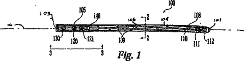
図1及び図2は、大腿に挿入して治療するために設計された本発明のIMロッドの好ましい実施形態を示している。IMロッドは、大腿用に説明されることになるが、その特徴は、上腕骨、橈骨/尺骨、大腿骨、脛骨/腓骨を含む長骨、又は他の骨のためのIMロッドにさえ適用されることが認められるであろう。本発明のIMロッドは、様々な骨折の治療用に設計され、好ましくは中心内腔102を含み、これは、骨髄内ロッド100の全長に延び、ヘッド部分105に外部への開口部103及びステム108に外部への開口部101を備え、挿管ロッドを作成するものである。挿管によって、案内及びアラインメントのために骨内に挿入されたガイドワイヤの上にロッドを配置することができる。同様に、ロッドの挿管は、IMロッドの直径がより小さいか又は長さがより短い場合のような望ましいか又は適切な場合には、省略することができる。ロッドは、様々な長さ及び直径で提供され、外科医がロッドの最終寸法を治療される患者の身体的及び医学的特徴に適正に適合させることを可能にすることができる。ロッドは、好ましくは、チタンのような生物学的非反応性金属、又はチタン合金のような金属合金、ステンレス鋼のような他の金属、又は非金属材料から成るが、他の材料も恐らく同様に用いることができると考えられる。
1 and 2 show a preferred embodiment of the IM rod of the present invention designed for insertion into a thigh for treatment. Although IM rods will be described for the femur, the features apply to IM rods for humerus, radius / ulna, femur, long bones including tibia / radius, or even other bones Will be accepted. The IM rod of the present invention is designed for the treatment of various fractures and preferably includes a
好ましくは、ロッド100は、図3に示すようにIMロッドの横−内側平面に位置する横開口部を含むことができる。ヘッド部分105は、任意的に、横孔120及び121、横孔130、及び/又は細長い横孔140を含むことができる。これらの開口部の各々は、外科医によって望ましい骨折固定特性を生成する角度でIMロッドを通して延びる軸線を有することができる。例えば、横孔120及び121は、好ましくは、ロッドの縦軸線から35度から75度の間の角度で、最も好ましくは、66度の角度で配向される。横孔120及び121は、平行軸線を有することができ、かつ等直径の内腔を有することができる。横孔130は、好ましくは、ロッドの縦軸線から25度から75度の角度で、最も好ましくは、45度の角度で配向される。細長い横孔140は、好ましくは、ロッドの縦軸線から5度から35度の間の角度で、最も好ましくは、16度の角度で配向される。これらの横開口部は、患部の骨の骨組織と係合する例えばネジ又はくぎのような横材を受けるような大きさである。例えば、大腿骨頸部骨折が治療される場合には、図4に示されている1つ又はそれよりも多くの大腿骨頸部ネジ200を横孔120及び121を通して、次に、大腿骨頭部内に挿入することができる。好ましくは、使用される大腿骨頸部ネジは、6.5mm直径のチタンラグネジである。異なる大きさの横孔120、121を異なる大きさの横材に適合するように設けることができる。第1の頸部ネジはまた、第2の頸部ネジと異なる大きさとすることができる。大腿骨頸部ネジのネジ付き端部210は、大腿骨頭部に係合及びそれを固定する一方、2つのこれらのネジの任意的使用は、大腿に対する大腿骨頭部の回転を防ぐものである。くぎ、螺旋ブレード、鋲、ボルト、ピンなどのような当業技術で公知の他の適切な固定横材は、それらが本明細書に説明する他のいかなる固定状況にも使用することができるように、大腿骨頭部の固定にも使用することができると想定されている。
Preferably, the rod 100 can include a lateral opening located in the lateral-inner plane of the IM rod as shown in FIG. The
大腿骨幹骨折の治療においては、止めネジが、横孔130及び/又は細長い孔140を通して、及び次に小転子内に挿入されて、縦方向及び捩れの両方に安定した固定をもたらすことができる。細長い孔140を通る単一止めネジの任意的使用により、大腿の近位部分がロッドの遠位端に対して移動することができ、それによって捩り固定のみをもたらす。くぎ(螺旋ブレードを有するものを含む)、鋲、ボルト、ピン、その他のような他の固定又は定着部材は、孔130、140を通して挿入することができる。
In the treatment of femoral shaft fractures, a set screw can be inserted through the
ロッドのステム108は、好ましくは、遠位横孔110、111、及び112を含む。遠位孔110及び112は、IMロッドの横−内側平面に配置することができる。遠位孔111は、好ましくは、遠位孔110及び112からロッドの縦軸線回りに25度だけ角度的にオフセットされる。止めネジが、骨を通って遠位孔111内に、及び遠位孔110、112のいずれか又は両方の中に挿入されて、ロッドの遠位部分を大腿に係止することができる。止めネジを異なる平面に挿入することにより、ロッドをより安定して骨に固定することができる。くぎ(螺旋ブレードを有するものを含む)、鋲、ボルト、ピン、その他のような他の固定又は定着部材は、孔110、111、112を通して挿入することができる。
The rod stem 108 preferably includes distal
ロッドのステム108は、ステム108の表面106に沿ってチャンネル104の間に形成された「縦溝」109を有するチャンネル状構造104を含む。縦溝は、好ましくは、ヘッド部分105の基部の下からステム108の遠位端に向って下方に延びる。最も好ましくは、縦溝109は、ロッドの近位端から約75mmから95mmで始まる。当業技術で公知の縦溝のように、縦溝109は、脊髄血管再開通術の改善、より大きな強度を伴う剛性の低減、及びロッド−骨インタフェースでの捩り固定の改善のような恩典をもたらす。好ましい実施形態では、図2に示すように、6つの縦溝109があるが、より多いか又は少ない縦溝を実施することができる。縦溝109は、好ましくは、ロッドの縦軸線10に平行な直線経路内でロッドのステムを下方に延びず、むしろ、図1で見ることができるように、ステム108の全長を渦巻又は螺旋様式で下方に延びている。縦溝は、好ましくは、その開始点から最終点まで移動する時に、IMロッドの縦軸線10の周囲を約90度回転するか又は捩れる。しかし、回転量は、必要に応じて変更することができる。回転方向は、一般的に、IMロッドが好ましくは患者の後背部に回転されるので、IMロッドが体の左側又は右側のどちらに挿入されるかに依存する。ロッドをその近位端からその遠位端に向って見ると、縦溝は、左側ロッドで反時計回りに、右側ロッドで時計回りに回転する。当然のことながら、回転方向は、IMロッドの用途及び構造によって変化する可能性があるであろう。
The
縦溝109は、好ましくは、ロッド100の螺旋状縦溝を形成するようにステムの表面をフライス加工することによって形成される。しかし、縦溝109はまた、当業者に公知の他の手段によっても形成することができる。更に、他の種類の表面変形又は突出が、縦溝109の役割を恐らく満たすことができると考えられる。
The
ロッド100は、好ましくは、大転子に位置して大腿の梨状陥凹からオフセットした侵入部位を通って髄管内に挿入されるので、縦溝109は、骨組織に係合する傾向にあり、従って、ロッドの捩れ運動を案内する。挿入中にロッドの回転を妨げる直線的な縦溝を有するIMロッドとは異なり、ロッド100の螺旋状縦溝109は、実際にロッドの捩りを助けるものである。縦軸線の周囲の螺旋の回転率は予め決められているので、適量の回転が挿入程度に応じてロッド100に加えられる。これは、湾曲したロッドの適正な挿入及び最終アラインメントを大いに容易にし、ロッド100の早期又は遅延した捩れのいずれかによる不慮の骨折の可能性を低減する。また、骨組織は、直線的な縦溝を有するIMロッドを捩ることで発生する切断からも回避される。
Since the rod 100 is preferably inserted into the medullary canal through an entry site located in the greater trochanter and offset from the piriform depression of the thigh, the
ロッドの大腿からの除去もまた、螺旋状縦溝109の存在によって容易にされる。治癒過程の間、骨成長によってIMロッド100が髄管内にきつく埋め込まれる場合がある。螺旋状縦溝109は、髄管から引っ張られる時にロッド100の回転を案内することによって除去を容易にし、適量の捩りをロッドに加え、それによって湾曲部分は、ロッド100が除去される時に骨に対するこのような横方向圧力を低減する。
Removal of the rod from the thigh is also facilitated by the presence of the spiral flutes 109. During the healing process, bone growth may cause the IM rod 100 to be tightly embedded in the medullary canal. The
ロッド100は、好ましくは、図6及び図7に示すように、全長に沿って3つの湾曲部分301、302、303を有し、好ましくは、湾曲の2つは、同一平面内に配置され、第3の湾曲は、好ましくは、直交表面に位置する。ロッドの様々な湾曲は、これらの複雑な湾曲をロッド100に組み込むことが可能な市販のコンピュータ制御曲げ機械を用いて形成される。これらの湾曲部分を生成する他の方法は公知であり、これもまた装置の構成に使用することができる。 The rod 100 preferably has three curved portions 301, 302, 303 along its entire length, as shown in FIGS. 6 and 7, preferably the two of the curves are arranged in the same plane, The third curvature is preferably located on the orthogonal surface. The various curvatures of the rod are formed using commercially available computer controlled bending machines that can incorporate these complex curvatures into the rod 100. Other methods of generating these curved portions are known and can also be used in the construction of the device.
第1の湾曲セグメント301は、好ましくは、近位ヘッド105で始まり、好ましくは、直線セグメント304で終結する。最も好ましくは、第1の湾曲301は、IMロッドの近位端から約26mmで始まり、約6.5度の円弧角に曲げられる。第1の湾曲301は、好ましくは、約100mmから約500mmの間、より好ましくは、約300mm(約11.8インチ)の曲率半径R1を有する。第1の湾曲は、異なる位置で始まり、異なる角度に曲げることができ、異なる曲率半径を有することができる。更に、第1の湾曲301の曲率半径R1は、第1の湾曲セグメントの長さにわたって変化することができる。第1の湾曲セグメントは、一実施形態では、約10mmから約60mmの長さを有することができ、より好ましくは、大腿に挿入のためのIMロッドに対して約34mmとすることができる。第1の湾曲セグメント301の長さは、設計の必要性に応じて上述の値よりも長く又は短くすることができる。ロッド100が大腿内のその最終位置に位置すると、第1の湾曲301は、図4及び図5に示すように、大腿の横−内側平面にあり、体から離れて横方向に転子の先端の侵入部位に向って方向付けられる。
The first curved segment 301 preferably begins with the
第2の湾曲セグメント302は、第1の湾曲301と同じ平面にあるが、第1の湾曲の終点を超えた点、好ましくは、ロッド100のヘッド105の下で始まる。最も好ましくは、第2の湾曲セグメント302は、IMロッドの近位端から約75mmで始まり、約8.5度の円弧角に曲げられる。IMロッドの直線セグメント304は、好ましくは、第1の湾曲セグメント301と第2の湾曲セグメント302を互いに分離する。第2の湾曲セグメント302は、好ましくは、約100mmから約1500mmの間、より好ましくは、約800mm(約31.5インチ)の曲率半径R2を有する。第2の湾曲セグメント302は、異なる位置で始まることができ、異なる曲率半径を有することができる。更に、第2の湾曲セグメント302の曲率半径R2は、第2の湾曲セグメント302の長さにわたって変化又は変更することができる。第2の湾曲セグメント302は、一実施形態では、約10mmから約220mmの長さとすることができ、より好ましくは、大腿に挿入のためのIMロッドに対する長さにおいて約120mmとすることができる。第2の湾曲セグメント302の長さは、設計の必要性に応じて上述の値よりも長く又は短くすることができる。
The second curved segment 302 is in the same plane as the first curved 301 but starts at a point beyond the first curved end point, preferably below the
第1及び第2の湾曲セグメント301、302の性質は、IMロッドが、好ましくは、挿入点から髄管内に延びる骨に形成される空洞の移行に対してIMロッドが仮に単に直線的であった場合よりもより適正に適合するような性質である。従って、骨髄内ロッドから骨に作用する不必要な横荷重の低減があり、これは、挿入又は除去過程から起こる不慮の2次骨折の危険性の低減に役立つものである。 The nature of the first and second curved segments 301, 302 was that the IM rod was simply linear with respect to the transition of the cavity formed in the bone, preferably the bone extending from the insertion point into the medullary canal It is a property that fits more appropriately than the case. Thus, there is a reduction in unnecessary lateral loads acting on the bone from the intramedullary rod, which helps to reduce the risk of accidental secondary fractures resulting from the insertion or removal process.
図7に示すように、第3の湾曲セグメント303は、好ましくは、70度から120度の間であり、より好ましくは、第1及び第2の湾曲セグメント301、302に直交し、好ましくは、髄管の前部湾曲に適合するように前部−後部平面に位置する。好ましくは、第3の湾曲303は、ロッド100のステム108に沿った点で始まる。最も好ましくは、第3の湾曲303は、IMロッドの近位端から約180mmで始まり、ロッドの端部まで続く。第3の湾曲は、好ましくは、約500mmから約2500mmの間、より好ましくは、約1000mm(約39.4インチ)の曲率半径R3を有する。第3の湾曲は、異なる位置で始まるか又は異なる位置で終わることができ、上述の値とは異なる曲率半径R3を有することができる。更に、第3の湾曲セグメント303の曲率半径R3は、第3の湾曲セグメント303の長さにわたって変化又は変更することができる。第3の湾曲セグメント303は、一実施形態では、約10mmからIMロッドの残りの長さまでの長さとすることができる。第3の湾曲セグメント303の長さは、設計の必要性に応じて上述の値よりも長く又は短くすることができる。
As shown in FIG. 7, the third curved segment 303 is preferably between 70 degrees and 120 degrees, more preferably orthogonal to the first and second curved segments 301, 302, preferably Located in the anterior-posterior plane to match the anterior curvature of the medullary canal. Preferably, the third curve 303 begins at a point along the
第3の湾曲セグメント303は、好ましくは、骨の自然な湾曲に適合する方法で形成され、従って、不慮の2次骨折の危険性を低減するのに役立つものである。第3の湾曲セグメント303はまた、好ましくは、第2の湾曲セグメント302に部分的に重なり、この部分を通して「捩れ」を有するロッド100をもたらす同一平面湾曲を形成する。すなわち、この重複部分305のIMロッドは、2つの表面で湾曲する。最も好ましくは、第2の湾曲302及び第3の湾曲303は、約20mmだけ互いに重なるが、重複量は、約0mmからIMロッドの全長の範囲内で変化することができる。螺旋状縦溝109と同様に、この捩れは、ロッドが髄管内に挿入される時にその縦軸線回りのロッドの回転の案内を助けるものである。この捩れの構成は、螺旋状縦溝がIMロッドを回転させるものと同じ回転方向へのロッドの回転をもたらす。
The third curved segment 303 is preferably formed in a manner that conforms to the natural curvature of the bone and thus helps to reduce the risk of accidental secondary fractures. The third curved segment 303 also preferably forms a coplanar curve that partially overlaps the second curved segment 302 resulting in the rod 100 having “twist” through this portion. That is, the IM rod of this overlapping
使用中、外科医は、患者の身体的特徴及び病状に基づき適正な大きさのIMロッド100を選択する。IMロッド100自体及び様々な横材の両方をロッドの近位横孔120、121、130、及び140内に挿入することを助けるために、挿入ハンドルの形態の案内ツール(図示せず)が、ロッドのヘッド部分105の上部に位置する好ましくはネジ式の孔160に取り付けられる。スロット170を使用して、ロッド100の縦軸線に関して挿入ハンドルをIMロッド100に整列させる。従って、IMロッド100が骨の髄管内にある時に、ロッド100の向きは、ハンドルの位置によって特定することができる。
In use, the surgeon selects the correct size IM rod 100 based on the patient's physical characteristics and medical condition. To help insert both the IM rod 100 itself and the various cross members into the rod's proximal
大転子の先端での骨切術が、侵入部位を作成するように行われ、可撓性リーマを使用して髄管に空洞を作成する。外科医は、次に、IMロッド100を、それがその最終位置からその縦軸線回りに90度回転されるように配向し、それによって湾曲開口部を有するロッドの前部−後部湾曲を侵入部位から髄管まで大雑把に配向する。外科医がIMロッド100のステムを髄管内に押し込むと、ロッドの螺旋状縦溝109及び同一平面湾曲は、様々な湾曲が骨を通る開口部に適合するようなIMロッド100の約90度の回転を案内するのに役立つ。
Osteotomy at the tip of the greater trochanter is performed to create the entry site and a flexible reamer is used to create a cavity in the medullary canal. The surgeon then orients the IM rod 100 so that it is rotated 90 degrees about its longitudinal axis from its final position, thereby causing the anterior-posterior curvature of the rod with a curved opening to be removed from the entry site. Roughly oriented to the medullary canal. When the surgeon pushes the stem of the IM rod 100 into the medullary canal, the
ロッド100が骨内の位置に完全に挿入された状態で、挿入ハンドル上の照準アームを使用して、ロッド100を通る横孔の位置を見つける。横材は、ロッド100を通るそれぞれの孔に整列させられ、骨内にロッドを通して挿入されて、治療される骨折の種類によって要求されるように骨を固定する。 With the rod 100 fully inserted into position in the bone, the aiming arm on the insertion handle is used to find the position of the transverse hole through the rod 100. The crosspiece is aligned with each hole through the rod 100 and inserted through the rod into the bone to secure the bone as required by the type of fracture to be treated.
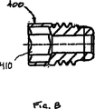
ロッド及び横材の挿入後、エンドキャップ400(図8に図示)が孔160に設けられ、孔内での骨成長を防ぐことができる。エンドキャップ400は、取り付けられた状態でロッド100のヘッド105内に引っ込むように設計される一方、代替エンドキャップ500(図10に図示)は、ロッド100のヘッド105を超えて延び、ロッドの全長を必要に応じて延長する。両方のエンドキャップには、適切な取り付けツールの挿入のためのソケット410(図9に図示)が設けられる。
After insertion of the rod and crosspiece, an end cap 400 (shown in FIG. 8) is provided in the hole 160 to prevent bone growth in the hole. The
IMロッドのある一定の好ましい実施形態及び特徴を説明して図解したが、多数の修正及び他の実施形態を当業者が考案することができることが認められるであろう。例えば、IMロッドは、大腿の用途に関して説明したが、IMロッドは、大きさ及び形状を任意的に変更して本明細書に記載の特徴の一部又は全てを用いて他の長骨の治療に用いることができると考えられる。本明細書に記載の特徴は、単一か又は組み合わせて用いることができる。従って、特許請求の範囲は、本発明の精神及び範囲に該当する全てのこのような修正及び実施形態を網羅し、本発明は、その最も広範な解釈を与える特許請求の範囲によって規定されるように意図していることが理解されるであろう。 While certain preferred embodiments and features of the IM rod have been described and illustrated, it will be appreciated that numerous modifications and other embodiments can be devised by those skilled in the art. For example, while the IM rod has been described with respect to femoral applications, the IM rod may be arbitrarily modified in size and shape to treat other long bones using some or all of the features described herein. It is thought that it can be used for. The features described herein can be used singly or in combination. Accordingly, the claims are intended to cover all such modifications and embodiments that fall within the spirit and scope of the present invention, and the invention is defined by the claims that give the broadest interpretation thereof. It will be understood that this is intended.
100 骨髄内ロッド
105 ヘッド部分
108 ステム
100
Claims (22)
縦軸線と、ヘッドと、ステムとを有する細長いロッドと、
前記細長いロッドを通って延びる少なくとも1つの第1横孔であって、該第1横孔は前記縦軸線に対しゼロ以外の角度をもつ第1横孔軸線を有し、該第1横孔軸線と前記縦軸線は第1平面を画定し、及び
前記ステムの少なくとも一部に沿って形成された複数の外側螺旋状突出部とを有し、
前記細長いロッドは、前記第1平面に直交しかつ前記縦軸線を含む第2平面を有し、前記長い骨は、第1平面内の少なくとも二つの縦曲がりと、前記第2平面内の少なくとも一つの縦曲がりを有し、
前記縦曲がりと複数の前記外側螺旋状突出部は、前記細長いロッドを髄管に挿入する間前記細長いロッドを前記縦軸線を中心に同一方向に回転させる
ことを特徴とする骨髄内ロッド。In an intramedullary rod for use in the treatment of long bone fractures,
An elongate rod having a longitudinal axis, a head, and a stem;
At least one first transverse hole extending through the elongated rod, the first transverse hole having a first transverse hole axis having a non-zero angle with respect to the longitudinal axis, the first transverse hole axis; And the longitudinal axis defines a first plane, and has a plurality of outer spiral protrusions formed along at least a portion of the stem,
The elongate rod has a second plane perpendicular to the first plane and including the longitudinal axis, and the long bone has at least two longitudinal turns in the first plane and at least one in the second plane. Has two vertical bends,
The intramedullary rod characterized in that the longitudinal bend and the plurality of outer spiral protrusions rotate the elongated rod in the same direction about the longitudinal axis while inserting the elongated rod into the medullary canal .
ことを特徴とする請求項1に記載の骨髄内ロッド。The at least two longitudinal bends in the first plane include a first curved segment having a first radius of curvature and a second curved segment having a second radius of curvature , the first radius of curvature comprising: Different from the second radius of curvature;
The intramedullary rod according to claim 1.
ことを特徴とする請求項6に記載の骨髄内ロッド。At least one of the longitudinal bends in the first plane overlaps at least one of the longitudinal bends in the second plane;
The intramedullary rod according to claim 6.
前記縦曲がりの第2の湾曲セグメントは、100mmと1500mmの間の曲率半径を有し、
前記第3の湾曲セグメントは、500mmと2500mmの間の曲率半径を有する、
ことを特徴とする請求項3に記載の骨髄内ロッド。The first curved segment of the longitudinal bend has a radius of curvature between 100 mm and 500 mm;
The second curved segment of the longitudinal bend has a radius of curvature between 100 mm and 1500 mm;
The third curved segment has a radius of curvature between 500 mm and 2500 mm;
The intramedullary rod according to claim 3.
ロッドの前記縦軸線に対して第1の角度に配向された実質的に平行な軸線を有する、前記ヘッドに位置した1対の孔と、
ロッドの前記縦軸線に対して第2の角度に配向された軸線を有する、前記ヘッドに位置した内腔と、
を含む、
ことを特徴とする請求項1に記載の骨髄内ロッド。The at least one lateral hole is
A pair of holes located in the head having a substantially parallel axis oriented at a first angle relative to the longitudinal axis of the rod;
A lumen located in the head having an axis oriented at a second angle relative to the longitudinal axis of the rod;
including,
The intramedullary rod according to claim 1.
を更に含むことを特徴とする請求項12に記載の骨髄内ロッド。At least two distally located in at least a portion of the stem having an axis oriented from about 85 degrees to about 95 degrees relative to the longitudinal axis of the rod and angularly offset from each other about the longitudinal axis Hole,
The intramedullary rod according to claim 12, further comprising:
縦軸線と、ヘッドと、ステムとを有する細長いロッドであって、該ヘッドと該ステムは最大外径を有し、前記ヘッドの最大外径は前記ステムの最大外径より大きく、
前記細長いロッドを通って延びる少なくとも1つの第1横孔であって、該第1横孔は前記縦軸線に対しゼロ以外の角度をもつ第1横孔軸線を有し、該第1横孔軸線と前記縦軸線は第1平面を画定し、及び
前記ステムの少なくとも一部に沿って形成された複数の外側螺旋状突出部とを有し、
前記長い骨は、前記第1平面に直交しかつ前記縦軸線を含む第2平面を有し、前記長い骨は、第1平面内の少なくとも二つの縦曲がりと、前記第2平面内の少なくとも一つの縦曲がりを有し、
前記縦曲がりと複数の前記外側螺旋状突出部は、前記細長いロッドを髄管に挿入する間前記細長いロッドを前記縦軸線を中心に同一方向に回転させる
ことを特徴とする骨髄内ロッド。In an intramedullary rod for use in the treatment of long bone fractures,
An elongated rod having a longitudinal axis, a head, and a stem, the head and the stem having a maximum outer diameter, the maximum outer diameter of the head being greater than the maximum outer diameter of the stem;
At least one first transverse hole extending through the elongated rod, the first transverse hole having a first transverse hole axis having a non-zero angle with respect to the longitudinal axis, the first transverse hole axis; And the longitudinal axis defines a first plane, and has a plurality of outer spiral protrusions formed along at least a portion of the stem,
The long bone has a second plane perpendicular to the first plane and including the longitudinal axis, the long bone having at least two longitudinal turns in the first plane and at least one in the second plane. Has two vertical bends,
The intramedullary rod characterized in that the longitudinal bend and the plurality of outer spiral protrusions rotate the elongated rod in the same direction about the longitudinal axis while inserting the elongated rod into the medullary canal .
Applications Claiming Priority (3)
| Application Number | Priority Date | Filing Date | Title |
|---|---|---|---|
| US10/866,597 US7771428B2 (en) | 2004-06-11 | 2004-06-11 | Intramedullary rod with spiraling flutes |
| US10/866,597 | 2004-06-11 | ||
| PCT/US2005/020361 WO2005122932A2 (en) | 2004-06-11 | 2005-06-08 | Intramedullary rod with spiraling flutes |
Publications (3)
| Publication Number | Publication Date |
|---|---|
| JP2008502454A JP2008502454A (en) | 2008-01-31 |
| JP2008502454A5 JP2008502454A5 (en) | 2008-07-24 |
| JP4932715B2 true JP4932715B2 (en) | 2012-05-16 |
Family
ID=35461474
Family Applications (1)
| Application Number | Title | Priority Date | Filing Date |
|---|---|---|---|
| JP2007527739A Active JP4932715B2 (en) | 2004-06-11 | 2005-06-08 | Intramedullary rod with spiral flutes |
Country Status (13)
| Country | Link |
|---|---|
| US (3) | US7771428B2 (en) |
| EP (2) | EP1765207B1 (en) |
| JP (1) | JP4932715B2 (en) |
| CN (1) | CN101010044B (en) |
| AT (2) | ATE549988T1 (en) |
| AU (1) | AU2005254006B2 (en) |
| BR (1) | BRPI0511936A (en) |
| CA (1) | CA2570013C (en) |
| ES (2) | ES2384500T3 (en) |
| NZ (1) | NZ552051A (en) |
| PL (2) | PL1765207T3 (en) |
| WO (1) | WO2005122932A2 (en) |
| ZA (1) | ZA200700094B (en) |
Families Citing this family (79)
| Publication number | Priority date | Publication date | Assignee | Title |
|---|---|---|---|---|
| US8702768B2 (en) | 2001-10-18 | 2014-04-22 | Orthoip, Llc | Cannulated bone screw system and method |
| US6736819B2 (en) | 2001-10-18 | 2004-05-18 | Kishore Tipirneni | System and method for fixation of bone fractures |
| US20100268285A1 (en) * | 2001-10-18 | 2010-10-21 | Orthoip, Llc | Bone screw system and method for the fixation of bone fractures |
| US8679167B2 (en) | 2001-10-18 | 2014-03-25 | Orthoip, Llc | System and method for a cap used in the fixation of bone fractures |
| US9060809B2 (en) | 2001-10-18 | 2015-06-23 | Orthoip, Llc | Lagwire system and method for the fixation of bone fractures |
| US8828067B2 (en) | 2001-10-18 | 2014-09-09 | Orthoip, Llc | Bone screw system and method |
| US20060015101A1 (en) * | 2004-07-15 | 2006-01-19 | Wright Medical Technology, Inc. | Intramedullary fixation assembly and devices and methods for installing the same |
| US7588577B2 (en) | 2004-07-15 | 2009-09-15 | Wright Medical Technology, Inc. | Guide assembly for intramedullary fixation and method of using the same |
| BRPI0419194B8 (en) * | 2004-10-14 | 2021-06-22 | Synthes Gmbh | intramedullary nail |
| JP5060308B2 (en) * | 2004-12-31 | 2012-10-31 | シンセス ゲゼルシャフト ミット ベシュレンクテル ハフツング | Intramedullary nail |
| US20070083202A1 (en) * | 2005-09-20 | 2007-04-12 | Donald Eli Running | Intramedullary bone plate with sheath |
| US20070123876A1 (en) * | 2005-10-31 | 2007-05-31 | Czartoski Timothy J | Multiple purpose nail, nail assembly and associated method |
| US20070123873A1 (en) * | 2005-10-31 | 2007-05-31 | Czartoski Timothy J | Intramedullary nail with oblique openings |
| US20070123874A1 (en) * | 2005-10-31 | 2007-05-31 | Czartoski Timothy J | Multiple purpose nail with oblique openings |
| KR101387162B1 (en) | 2006-05-09 | 2014-04-21 | 신세스 게엠바하 | Nail system and method for an olecaranon osteotomy |
| US10687869B2 (en) * | 2006-07-05 | 2020-06-23 | Advanced Orthopaedic Solutions, Inc. | Trochanteric nail with locking opening |
| US8579985B2 (en) | 2006-12-07 | 2013-11-12 | Ihip Surgical, Llc | Method and apparatus for hip replacement |
| US8029573B2 (en) * | 2006-12-07 | 2011-10-04 | Ihip Surgical, Llc | Method and apparatus for total hip replacement |
| US8974540B2 (en) | 2006-12-07 | 2015-03-10 | Ihip Surgical, Llc | Method and apparatus for attachment in a modular hip replacement or fracture fixation device |
| US8147495B2 (en) * | 2007-01-16 | 2012-04-03 | Warsaw Orthopedic, Inc. | Methods and kits for treating fractures with a biological agent |
| US7918853B2 (en) | 2007-03-20 | 2011-04-05 | Smith & Nephew, Inc. | Orthopaedic plate and screw assembly |
| EP2129309A2 (en) | 2007-03-22 | 2009-12-09 | Novalign Orthopaedics, Inc. | Segmented intramedullary structure |
| AU2008256740A1 (en) | 2007-05-25 | 2008-12-04 | Zimmer, Gmbh | Reinforced intramedullary nail |
| CA2690786C (en) * | 2007-06-22 | 2015-12-15 | Anthem Orthopaedics Van, Llc | Intramedullary rod for pivoting a fastener |
| ES2435573T3 (en) * | 2007-11-26 | 2013-12-20 | Biedermann Motech Gmbh & Co. Kg | Orthopedic heel nail |
| US8771283B2 (en) | 2007-12-17 | 2014-07-08 | Wright Medical Technology, Inc. | Guide assembly for intramedullary fixation and method of using the same |
| CA2781407A1 (en) | 2008-01-14 | 2009-07-23 | Michael P. Brenzel | Apparatus and methods for fracture repair |
| JP2011519658A (en) * | 2008-05-07 | 2011-07-14 | トゥルニエ | Humeral nail |
| US9044282B2 (en) * | 2008-06-24 | 2015-06-02 | Extremity Medical Llc | Intraosseous intramedullary fixation assembly and method of use |
| US8303589B2 (en) | 2008-06-24 | 2012-11-06 | Extremity Medical Llc | Fixation system, an intramedullary fixation assembly and method of use |
| US20110125153A1 (en) * | 2008-06-24 | 2011-05-26 | Jeff Tyber | Intramedullary fixation assembly and method of use |
| US9017329B2 (en) | 2008-06-24 | 2015-04-28 | Extremity Medical, Llc | Intramedullary fixation assembly and method of use |
| US8313487B2 (en) | 2008-06-24 | 2012-11-20 | Extremity Medical Llc | Fixation system, an intramedullary fixation assembly and method of use |
| US8328806B2 (en) | 2008-06-24 | 2012-12-11 | Extremity Medical, Llc | Fixation system, an intramedullary fixation assembly and method of use |
| US20100121325A1 (en) * | 2008-06-24 | 2010-05-13 | Jeff Tyber | Hybrid intramedullary fixation assembly and method of use |
| US9289220B2 (en) | 2008-06-24 | 2016-03-22 | Extremity Medical Llc | Intramedullary fixation assembly and method of use |
| US8343199B2 (en) | 2008-06-24 | 2013-01-01 | Extremity Medical, Llc | Intramedullary fixation screw, a fixation system, and method of fixation of the subtalar joint |
| US8790343B2 (en) * | 2008-10-11 | 2014-07-29 | Epix Orthopaedics, Inc. | Intramedullary rod with pivotable and fixed fasteners and method for using same |
| EP2349040B9 (en) | 2008-10-15 | 2014-12-17 | Zimmer GmbH | Intramedullary nail |
| US8454706B2 (en) | 2009-02-25 | 2013-06-04 | Brian C. de Beaubien | Antibiotic delivery system and method for treating an infected synovial joint during re-implantation of an orthopedic prosthesis |
| CA2765376C (en) * | 2009-06-30 | 2017-06-06 | Smith & Nephew, Inc. | Orthopaedic implant and fastener assembly |
| EP2459085B1 (en) * | 2009-07-28 | 2017-01-25 | Synthes GmbH | Locking system for orthopedic implants |
| US20110178520A1 (en) | 2010-01-15 | 2011-07-21 | Kyle Taylor | Rotary-rigid orthopaedic rod |
| EP2523616B1 (en) | 2010-01-20 | 2019-04-17 | Conventus Orthopaedics, Inc. | Apparatus for bone access and cavity preparation |
| US8556896B2 (en) * | 2010-01-27 | 2013-10-15 | Zimmer, Inc. | Distal relief for a surgical device |
| US9579132B2 (en) * | 2010-02-24 | 2017-02-28 | William R. Krause | Flexible intramedullary nail |
| US8906022B2 (en) | 2010-03-08 | 2014-12-09 | Conventus Orthopaedics, Inc. | Apparatus and methods for securing a bone implant |
| US8540714B2 (en) * | 2010-05-11 | 2013-09-24 | Orthopediatrics Corp. | Pediatric intramedullary nail |
| BR112013020956B1 (en) * | 2011-02-14 | 2020-12-08 | Synthes Gmbh | bone fixation set |
| AU2011376744B2 (en) | 2011-09-16 | 2015-03-26 | Stryker European Operations Holdings Llc | Intramedullary nail locking hole arrangement |
| CN104411259B (en) | 2012-02-08 | 2017-06-13 | Epix整形外科股份有限公司 | The implant insertion apparatus of the aiming component with continuously adjustable |
| RU2506920C2 (en) * | 2012-03-20 | 2014-02-20 | Государственное бюджетное образовательное учреждение высшего профессионального образования "Дагестанская государственная медицинская академия министерства здравоохранения и социального развития" | Device for intramedullary osteosynthesis of femoral bone |
| US11051864B2 (en) * | 2012-08-30 | 2021-07-06 | DePuy Synthes Products, Inc. | Intramedullary fixation assembly |
| DE202012103384U1 (en) * | 2012-09-05 | 2012-09-24 | Signus Medizintechnik Gmbh | Pelvic ring implant |
| ES2578295T3 (en) * | 2012-11-14 | 2016-07-22 | Biedermann Technologies Gmbh & Co. Kg | Heel bone nail |
| US9301783B2 (en) | 2013-01-23 | 2016-04-05 | Fixx Orthopedics, LLC | Orthopedic external fixation device |
| US10883532B2 (en) | 2013-03-14 | 2021-01-05 | William R. Krause | Flexible shaft for use as an internal splint for industrial application |
| US10123828B2 (en) | 2013-03-15 | 2018-11-13 | Epix Orthopaedics, Inc. | Implantable device with pivotable fastener and self-adjusting set screw |
| EP2967686B1 (en) * | 2013-03-15 | 2023-09-06 | Paragon 28, Inc. | Intramedullary nail |
| DE102013005414A1 (en) * | 2013-03-28 | 2014-10-02 | Dietmar Wolter | Osteosynthesis system for the multidirectional, angularly stable treatment of fractures of long bones including an intramedullary nail and bone screws |
| US20170042591A9 (en) * | 2013-12-12 | 2017-02-16 | Extremity Designs, Llc | Intramedullary anchor-screw fracture fixation |
| CA2969316A1 (en) | 2013-12-12 | 2015-06-18 | Conventus Orthopaedics, Inc. | Tissue displacement tools and methods |
| USD904616S1 (en) | 2014-03-14 | 2020-12-08 | Paragon 28, Inc. | Intramedullary fastener |
| JP2017520282A (en) * | 2014-04-11 | 2017-07-27 | スミス アンド ネフュー インコーポレイテッド | DMLS orthopedic intramedullary device and method of manufacture |
| US10045803B2 (en) | 2014-07-03 | 2018-08-14 | Mayo Foundation For Medical Education And Research | Sacroiliac joint fusion screw and method |
| WO2016000784A1 (en) * | 2014-07-03 | 2016-01-07 | Stryker Trauma Gmbh | Conical end cap for intramedullary nail |
| WO2016100158A1 (en) | 2014-12-15 | 2016-06-23 | Smith & Nephew, Inc. | Active fracture compression implants |
| WO2016138220A1 (en) | 2015-02-27 | 2016-09-01 | Thomas Gerold | Orthopedic external fixation device |
| CA2986540A1 (en) * | 2015-05-22 | 2016-12-01 | Stryker European Holdings I, Llc | Implant system for bone fixation |
| US10433965B2 (en) * | 2015-06-17 | 2019-10-08 | Joint Purification Systems Llc | Total joint replacement infection control devices and methods |
| CN105125266A (en) * | 2015-10-10 | 2015-12-09 | 陈伟 | Self-tapping intramedullary fixation device suitable for long bone fractures |
| US9833321B2 (en) | 2016-04-25 | 2017-12-05 | Imds Llc | Joint fusion instrumentation and methods |
| US10413332B2 (en) | 2016-04-25 | 2019-09-17 | Imds Llc | Joint fusion implant and methods |
| CN108236526A (en) * | 2016-12-27 | 2018-07-03 | 重庆润泽医药有限公司 | Bone surgery tantalum stick equipment |
| US10251682B2 (en) | 2017-03-22 | 2019-04-09 | DePuy Synthes Products, Inc. | Distal radius nail |
| US10918426B2 (en) | 2017-07-04 | 2021-02-16 | Conventus Orthopaedics, Inc. | Apparatus and methods for treatment of a bone |
| CA3078249A1 (en) | 2017-10-11 | 2019-04-18 | Tornier, Inc. | Humeral fixation plate guides |
| US11013540B2 (en) * | 2018-04-13 | 2021-05-25 | Stryker European Operations Holdings Llc | Femoral nail with enhanced bone conforming geometry |
| CN116133605A (en) | 2020-05-29 | 2023-05-16 | 史赛克欧洲运营有限公司 | Funnel hole for intramedullary nail |
Family Cites Families (39)
| Publication number | Priority date | Publication date | Assignee | Title |
|---|---|---|---|---|
| US1274470A (en) * | 1917-05-11 | 1918-08-06 | Charles L Thornberry | Means for securing wood flooring and trimming in place in fireproof buildings. |
| US3433220A (en) | 1966-12-30 | 1969-03-18 | Robert E Zickel | Intramedullary rod and cross-nail assembly for treating femur fractures |
| CH492447A (en) | 1968-06-17 | 1970-06-30 | Xavier Halloran William | Fixation device for broken bones |
| US3709218A (en) * | 1970-04-24 | 1973-01-09 | W Halloran | Combination intramedullary fixation and external bone compression apparatus |
| US3977398A (en) | 1976-01-12 | 1976-08-31 | The Sampson Corporation | Fluted sub-trochanteric nail system |
| US4135507A (en) | 1977-05-20 | 1979-01-23 | Harris Leslie J | Condylocephalic nail for fixation of pertrochanteric fractures |
| US4169470A (en) * | 1977-10-19 | 1979-10-02 | Ender Hans G | Surgical nail for use in setting bone fractures, and tool for emplacing same |
| US4503847A (en) | 1982-01-15 | 1985-03-12 | Howmedica, Inc. | Prosthetic nail |
| US4546501A (en) * | 1982-09-28 | 1985-10-15 | Gustilo Ramon B | Hip prosthesis |
| US4475545A (en) | 1982-12-06 | 1984-10-09 | Ender Hans G | Bone-nail |
| US4976258A (en) | 1983-03-09 | 1990-12-11 | Howmedica International, Inc. | Locking nail |
| US4622959A (en) | 1985-03-05 | 1986-11-18 | Marcus Randall E | Multi-use femoral intramedullary nail |
| RO89820B1 (en) * | 1985-11-05 | 2002-06-28 | îNTREPRINDEREA INDUSTRIA TEHNICO MEDICALA | Elastic implants for a stable elastic osteorrhaphy of femoral and tibial fractures, respectively, as well as corresponding instrumentation |
| US5312406A (en) | 1986-12-30 | 1994-05-17 | Smith & Nephew Richards Inc. | Method of treating an intertrochanteric fracture |
| US4827917A (en) | 1986-12-30 | 1989-05-09 | Richards Medical Company | Fermoral fracture device |
| US5167663A (en) | 1986-12-30 | 1992-12-01 | Smith & Nephew Richards Inc. | Femoral fracture device |
| US4805607A (en) * | 1987-12-03 | 1989-02-21 | Boehringer Mannheim Corporation | Modular intramedullary nail system |
| US5176681A (en) | 1987-12-14 | 1993-01-05 | Howmedica International Inc. | Intramedullary intertrochanteric fracture fixation appliance and fitting device |
| CH674613A5 (en) | 1988-03-14 | 1990-06-29 | Synthes Ag | |
| US5066296A (en) | 1989-02-02 | 1991-11-19 | Pfizer Hopsital Products Group, Inc. | Apparatus for treating a fracture |
| GB9113578D0 (en) | 1991-06-24 | 1991-08-14 | Howmedica | Intramedullary intertrochanteric fracture fixation appliance |
| DE9115201U1 (en) | 1991-12-07 | 1992-02-06 | Howmedica Gmbh, 2314 Schoenkirchen, De | |
| DE4318150C2 (en) | 1993-06-01 | 1996-08-01 | Endocare Ag | Osteosynthesis tools for the treatment of subtrochanteric and pertrochanteric fractures as well as fractures of the femoral neck |
| SE510158C2 (en) * | 1992-10-29 | 1999-04-26 | Medevelop Ab | Anchorage elements for supporting prostheses and the use of such anchorage elements for fixing dentures |
| SE9301407D0 (en) * | 1993-04-27 | 1993-04-27 | Medevelop Ab | BEFORE IMPLANTATION IN WEAVEN PROVIDED FOR THE ANCHORING ORGANIZATION FOR THE PROCESSING OF PROCESSES, ARTIFICIAL ARTICLE COMPONENTS OR LIKE |
| JP2711802B2 (en) | 1994-02-10 | 1998-02-10 | ナカシマプロペラ株式会社 | Intramedullary nail |
| GB9411693D0 (en) | 1994-06-10 | 1994-08-03 | Matthews Michael G | Surgical intramedullary nail for stabilisation of condylar and supracondylar fractures |
| US5489284A (en) * | 1994-07-15 | 1996-02-06 | Smith & Nephew Richards Inc. | Cannulated modular intramedullary nail |
| US5549610A (en) | 1994-10-31 | 1996-08-27 | Smith & Nephew Richards Inc. | Femoral intramedullary nail |
| JP3345235B2 (en) | 1995-01-30 | 2002-11-18 | 旭光学工業株式会社 | Intramedullary nail for humerus |
| WO1997003611A1 (en) * | 1995-07-18 | 1997-02-06 | Edwards, Garland, U. | Flexible shaft |
| EP1342453B1 (en) | 1997-03-19 | 2005-08-24 | Stryker Trauma GmbH | Modular intramedullary nail |
| US6010506A (en) | 1998-09-14 | 2000-01-04 | Smith & Nephew, Inc. | Intramedullary nail hybrid bow |
| US6120504A (en) | 1998-12-10 | 2000-09-19 | Biomet Inc. | Intramedullary nail having dual distal bore formation |
| ATE400228T1 (en) | 1999-05-12 | 2008-07-15 | Zimmer Gmbh | LOCKING NAIL FOR THE TREATMENT OF FEMUR SHAFT FRACTURES |
| US6235031B1 (en) | 2000-02-04 | 2001-05-22 | Encore Medical Corporation | Intramedullary fracture fixation device |
| US6210414B1 (en) | 2000-04-20 | 2001-04-03 | Chin Lin | Bone fastener for shinbone and thighbone |
| JP4070978B2 (en) * | 2000-11-08 | 2008-04-02 | デピュイ・オーソピーディックス・インコーポレイテッド | Modular prosthesis having a stem component with an internally drilled cavity formed therein and associated method |
| EP1260188B1 (en) | 2001-05-25 | 2014-09-17 | Zimmer GmbH | Femoral bone nail for implantation in the knee |
-
2004
- 2004-06-11 US US10/866,597 patent/US7771428B2/en active Active
-
2005
- 2005-06-08 EP EP05758432A patent/EP1765207B1/en active Active
- 2005-06-08 JP JP2007527739A patent/JP4932715B2/en active Active
- 2005-06-08 AT AT10190561T patent/ATE549988T1/en active
- 2005-06-08 CN CN2005800268438A patent/CN101010044B/en active Active
- 2005-06-08 ZA ZA200700094A patent/ZA200700094B/en unknown
- 2005-06-08 AU AU2005254006A patent/AU2005254006B2/en not_active Expired - Fee Related
- 2005-06-08 ES ES10190561T patent/ES2384500T3/en active Active
- 2005-06-08 AT AT05758432T patent/ATE517582T1/en active
- 2005-06-08 CA CA2570013A patent/CA2570013C/en active Active
- 2005-06-08 EP EP10190561A patent/EP2301459B1/en active Active
- 2005-06-08 PL PL05758432T patent/PL1765207T3/en unknown
- 2005-06-08 ES ES05758432T patent/ES2369698T3/en active Active
- 2005-06-08 NZ NZ552051A patent/NZ552051A/en unknown
- 2005-06-08 BR BRPI0511936-7A patent/BRPI0511936A/en not_active Application Discontinuation
- 2005-06-08 WO PCT/US2005/020361 patent/WO2005122932A2/en active Application Filing
- 2005-06-08 PL PL10190561T patent/PL2301459T3/en unknown
-
2010
- 2010-06-30 US US12/827,480 patent/US8568414B2/en active Active
-
2013
- 2013-10-09 US US14/050,066 patent/US9192416B2/en active Active
Also Published As
| Publication number | Publication date |
|---|---|
| US20140039496A1 (en) | 2014-02-06 |
| WO2005122932A2 (en) | 2005-12-29 |
| ATE549988T1 (en) | 2012-04-15 |
| CA2570013A1 (en) | 2005-12-29 |
| EP2301459A1 (en) | 2011-03-30 |
| US20100268229A1 (en) | 2010-10-21 |
| JP2008502454A (en) | 2008-01-31 |
| EP1765207B1 (en) | 2011-07-27 |
| US7771428B2 (en) | 2010-08-10 |
| US8568414B2 (en) | 2013-10-29 |
| US9192416B2 (en) | 2015-11-24 |
| US20050277936A1 (en) | 2005-12-15 |
| ES2384500T3 (en) | 2012-07-05 |
| AU2005254006B2 (en) | 2010-09-16 |
| BRPI0511936A (en) | 2008-01-22 |
| PL2301459T3 (en) | 2012-09-28 |
| PL1765207T3 (en) | 2012-03-30 |
| EP1765207A4 (en) | 2009-03-25 |
| AU2005254006A1 (en) | 2005-12-29 |
| WO2005122932A3 (en) | 2006-05-11 |
| ZA200700094B (en) | 2008-06-25 |
| CN101010044A (en) | 2007-08-01 |
| EP1765207A2 (en) | 2007-03-28 |
| CN101010044B (en) | 2011-09-28 |
| CA2570013C (en) | 2013-05-21 |
| NZ552051A (en) | 2010-04-30 |
| EP2301459B1 (en) | 2012-03-21 |
| ES2369698T3 (en) | 2011-12-05 |
| ATE517582T1 (en) | 2011-08-15 |
Similar Documents
| Publication | Publication Date | Title |
|---|---|---|
| JP4932715B2 (en) | Intramedullary rod with spiral flutes | |
| EP2018127B1 (en) | Hip helical implant | |
| JP5409013B2 (en) | Method and instrument for fracture fixation | |
| EP0853923B1 (en) | Intramedullary cavity nail for the treatment of fractures of the hip | |
| US11051864B2 (en) | Intramedullary fixation assembly | |
| US20110218576A1 (en) | Plating Concept for Distal Radial Fractures | |
| US20110066190A1 (en) | Humeral Head Fixation Device for Osteoporotic Bone | |
| US8668693B2 (en) | Fixation device for proximal elbow fractures and method of using same | |
| WO2008064059A2 (en) | Sliding hip helical implant | |
| KR101200899B1 (en) | Intramedullary rod with spiraling flutes | |
| RU2362504C1 (en) | Intramedullary nail for ulnar bone | |
| US20230338066A1 (en) | Retrograde femoral intramedullary nail, and related systems and methods | |
| US20220240994A1 (en) | Fixation Device And Method Of Using The Same | |
| WO2008097795A1 (en) | Sliding hip helical implant |
Legal Events
| Date | Code | Title | Description |
|---|---|---|---|
| A521 | Request for written amendment filed |
Free format text: JAPANESE INTERMEDIATE CODE: A523 Effective date: 20080606 |
|
| A621 | Written request for application examination |
Free format text: JAPANESE INTERMEDIATE CODE: A621 Effective date: 20080606 |
|
| A131 | Notification of reasons for refusal |
Free format text: JAPANESE INTERMEDIATE CODE: A131 Effective date: 20101220 |
|
| A601 | Written request for extension of time |
Free format text: JAPANESE INTERMEDIATE CODE: A601 Effective date: 20110322 |
|
| A602 | Written permission of extension of time |
Free format text: JAPANESE INTERMEDIATE CODE: A602 Effective date: 20110329 |
|
| A521 | Request for written amendment filed |
Free format text: JAPANESE INTERMEDIATE CODE: A523 Effective date: 20110420 |
|
| A131 | Notification of reasons for refusal |
Free format text: JAPANESE INTERMEDIATE CODE: A131 Effective date: 20110523 |
|
| A601 | Written request for extension of time |
Free format text: JAPANESE INTERMEDIATE CODE: A601 Effective date: 20110822 |
|
| A602 | Written permission of extension of time |
Free format text: JAPANESE INTERMEDIATE CODE: A602 Effective date: 20110829 |
|
| A521 | Request for written amendment filed |
Free format text: JAPANESE INTERMEDIATE CODE: A523 Effective date: 20111122 |
|
| TRDD | Decision of grant or rejection written | ||
| A01 | Written decision to grant a patent or to grant a registration (utility model) |
Free format text: JAPANESE INTERMEDIATE CODE: A01 Effective date: 20120123 |
|
| A01 | Written decision to grant a patent or to grant a registration (utility model) |
Free format text: JAPANESE INTERMEDIATE CODE: A01 |
|
| A61 | First payment of annual fees (during grant procedure) |
Free format text: JAPANESE INTERMEDIATE CODE: A61 Effective date: 20120215 |
|
| R150 | Certificate of patent or registration of utility model |
Ref document number: 4932715 Country of ref document: JP Free format text: JAPANESE INTERMEDIATE CODE: R150 Free format text: JAPANESE INTERMEDIATE CODE: R150 |
|
| FPAY | Renewal fee payment (event date is renewal date of database) |
Free format text: PAYMENT UNTIL: 20150224 Year of fee payment: 3 |
|
| R250 | Receipt of annual fees |
Free format text: JAPANESE INTERMEDIATE CODE: R250 |
|
| R250 | Receipt of annual fees |
Free format text: JAPANESE INTERMEDIATE CODE: R250 |
|
| R250 | Receipt of annual fees |
Free format text: JAPANESE INTERMEDIATE CODE: R250 |
|
| R250 | Receipt of annual fees |
Free format text: JAPANESE INTERMEDIATE CODE: R250 |
|
| R250 | Receipt of annual fees |
Free format text: JAPANESE INTERMEDIATE CODE: R250 |
|
| R250 | Receipt of annual fees |
Free format text: JAPANESE INTERMEDIATE CODE: R250 |
|
| R250 | Receipt of annual fees |
Free format text: JAPANESE INTERMEDIATE CODE: R250 |
|
| R250 | Receipt of annual fees |
Free format text: JAPANESE INTERMEDIATE CODE: R250 |
|
| R250 | Receipt of annual fees |
Free format text: JAPANESE INTERMEDIATE CODE: R250 |
|
| R250 | Receipt of annual fees |
Free format text: JAPANESE INTERMEDIATE CODE: R250 |