JP4931546B2 - Solid-state imaging device and imaging device - Google Patents
Solid-state imaging device and imaging device Download PDFInfo
- Publication number
- JP4931546B2 JP4931546B2 JP2006288689A JP2006288689A JP4931546B2 JP 4931546 B2 JP4931546 B2 JP 4931546B2 JP 2006288689 A JP2006288689 A JP 2006288689A JP 2006288689 A JP2006288689 A JP 2006288689A JP 4931546 B2 JP4931546 B2 JP 4931546B2
- Authority
- JP
- Japan
- Prior art keywords
- signal
- output
- correction
- level
- conversion
- Prior art date
- Legal status (The legal status is an assumption and is not a legal conclusion. Google has not performed a legal analysis and makes no representation as to the accuracy of the status listed.)
- Expired - Fee Related
Links
Images


Classifications
-
- H—ELECTRICITY
- H04—ELECTRIC COMMUNICATION TECHNIQUE
- H04N—PICTORIAL COMMUNICATION, e.g. TELEVISION
- H04N25/00—Circuitry of solid-state image sensors [SSIS]; Control thereof
- H04N25/60—Noise processing, e.g. detecting, correcting, reducing or removing noise
- H04N25/63—Noise processing, e.g. detecting, correcting, reducing or removing noise applied to dark current
Description
本発明は、アナログ画像信号をデジタル画像データに変換して出力する機能を有する固体撮像装置及び撮像装置に関する。 The present invention relates to a solid-state imaging device and an imaging device having a function of converting an analog image signal into digital image data and outputting the digital image data.
従来、撮像装置に用いる固体撮像装置として、画素アレイ部を構成する複数の画素毎に、光電変換を行うフォトダイオードと、このフォトダイオードで生成した信号電荷を読み出す読み出しトランジスタと、読み出された信号電荷を画素信号に変換する増幅トランジスタと、信号電荷をリセットするリセットトランジスタと、読み出す画素を選択する選択トランジスタ等を設けたCMOSイメージセンサが提供されている。また、このようなCMOSイメージセンサでは、画素アレイ部から出力される画像信号に対し各種の処理を行う周辺回路部を有する構成となっており、固体撮像装置内でデジタル画像データに変換して出力するように構成されたものが知られている。 Conventionally, as a solid-state imaging device used for an imaging device, a photodiode that performs photoelectric conversion for each of a plurality of pixels that constitute a pixel array unit, a reading transistor that reads signal charges generated by the photodiode, and a read signal There is provided a CMOS image sensor provided with an amplifying transistor for converting charge into a pixel signal, a reset transistor for resetting signal charge, a selection transistor for selecting a pixel to be read out, and the like. In addition, such a CMOS image sensor has a peripheral circuit unit that performs various processing on the image signal output from the pixel array unit, and converts the image signal into digital image data and outputs it in the solid-state imaging device. What is configured to do so is known.
また、イメージセンサ自体にデジタル化する機能がない場合でも、固体撮像装置から出力されるアナログ画像信号を外部回路でデジタル化し、さらに様々なデジタル処理を施して出力するようなカメラ装置等の撮像装置が各種提供されており、この場合には、固体撮像装置としてアナログ出力型のCMOSイメージセンサやCCDイメージセンサを広く適用することが可能である。また、イメージセンサとカメラ装置との中間的なモジュールとして、CMOSイメージセンサやCCDイメージセンサと外部回路をパッケージ化してセンサモジュールとした撮像装置も提供されている。 In addition, even when the image sensor itself does not have a digitizing function, an imaging device such as a camera device that digitizes an analog image signal output from a solid-state imaging device with an external circuit and outputs various digital processes. In this case, analog output type CMOS image sensors and CCD image sensors can be widely applied as solid-state imaging devices. Further, as an intermediate module between the image sensor and the camera device, an imaging device is also provided in which a CMOS image sensor or a CCD image sensor and an external circuit are packaged to form a sensor module.
ところで、この種の固体撮像装置において、暗電流を除去する機能を有することは必須項目であり、例えば画素アレイ部の一部に設けた遮光画素(オプティカルブラック(OB))から検出される黒基準信号を適正に補正して目標値にクランプすることにより、素子間で生じる暗電流のばらつきや撮像動作時に生じる暗電流の変動に対応する方法が種々提案されている。
例えば、入力信号に含まれるアナログ黒基準信号を検出して目標値と比較し、その比較結果から誤差信号を算出してフィードバックをかけ、誤差信号によって入力信号を補正した後、さらにデジタル演算処理を用いて正確な補正値を算出すような構成が提案されている(例えば特許文献1参照)。
また、同様の処理を、アナログ信号のフィードバックを行わずに、デジタル信号のクランプ補正処理だけで行うことにより、回路を簡素化したものも提案されている(例えば特許文献2参照)。
For example, an analog black reference signal included in the input signal is detected and compared with a target value, an error signal is calculated from the comparison result, feedback is applied, the input signal is corrected by the error signal, and further digital arithmetic processing is performed. There has been proposed a configuration in which an accurate correction value is calculated by using (see, for example, Patent Document 1 ).
In addition, there has also been proposed a circuit that is simplified by performing the same processing only by clamp correction processing of a digital signal without performing feedback of an analog signal (see, for example, Patent Document 2 ).
しかしながら、上述したアナログ信号のフィードバックによる補正とデジタル演算処理による補正とを組み合わせた従来技術では、アナログ信号の補正用に回路を設ける分だけ回路規模が大きくなること、及びノイズ経路が増えることで、元信号の劣化を引き起こし易いという問題がある。特に、小型のチップの中に様々な機能を持たせたい固体撮像装置において、回路規模の増大は、他の機能の搭載を犠牲にすることにもなり、好ましくない。 However, in the conventional technique that combines the correction by the feedback of the analog signal and the correction by the digital arithmetic processing described above, the circuit scale is increased by providing a circuit for the correction of the analog signal, and the noise path is increased. There is a problem that the original signal is likely to be deteriorated. In particular, in a solid-state imaging device in which various functions are desired to be provided in a small chip, an increase in circuit scale is not preferable because it sacrifices mounting of other functions.
また、上述したアナログ信号のフィードバック回路を用いず、デジタル信号のクランプ補正処理で行う従来技術では、暗電流の変動が大きい固体撮像装置において、単にデジタルクランプ処理を行うだけになり、補正のダイナミックレンジが狭いという問題がある。特に、画像信号にアナログゲイン制御をかけたときに、オプティカルブラック値も同じように増幅されてしまうため、デジタル処理単独では補正能力に限界があった。
なお、以上のような問題は、黒基準信号の補正に限らず、画素信号に含まれる種々の信号(例えば、無フィルタ画素信号や特定波長光の検出信号等)を補正するような場合にも同様に生じるものである。
In addition, in the conventional technology that uses digital signal clamp correction processing without using the analog signal feedback circuit described above, the digital clamp processing is simply performed in a solid-state imaging device with large fluctuations in dark current, and the correction dynamic range is reduced. There is a problem that is narrow. In particular, when analog gain control is applied to an image signal, the optical black value is also amplified in the same manner, so that digital processing alone has a limit in correction capability.
The above problems are not limited to the correction of the black reference signal, but also when various signals included in the pixel signal (for example, an unfiltered pixel signal, a detection signal of specific wavelength light, etc.) are corrected. It happens in the same way.
そこで本発明は、画素信号に含まれる所定の信号を補正する場合に、アナログフィードバック回路を用いることなく、十分な能力の補正を行うことが可能な固体撮像装置及び撮像装置を提供することを目的とする。 Accordingly, the present invention provides a solid-state imaging device and an imaging device capable of performing sufficient capability correction without using an analog feedback circuit when correcting a predetermined signal included in a pixel signal. And
上記課題を解決し、本発明の目的を達成するため、本発明の固体撮像装置は、それぞれ光電変換部を有する複数の画素より構成される画素アレイ部と、この画素アレイ部から出力される画素信号を出力画像信号に変換する信号変換回路と、信号変換回路の出力画像信号に含まれるクランプレベルを補正するクランプ補正回路と、を有している。そして、クランプ補正回路は、出力画像信号のA/D変換を行うとともに、このA/D変換の際に出力画像信号に割り当てられるビット数Nに補正用のMビットを追加したN+Mビットのデジタルデータを生成して出力するA/D変換手段と、A/D変換手段によって出力されたN+Mビットのデジタルデータと、ランダムノイズやチャネル間段差、フレーム段差を補正した値にオフセットレベルを考慮した値とに基づいて補正値を決定する補正値生成手段と、A/D変換手段によって出力されたN+Mビットのデジタルデータと、補正値生成手段によって出力された補正値によって補正演算を行い、補正演算後の下位Nビットのクランプ補正データを生成する演算手段と、を有している。 In order to solve the above-described problems and achieve the object of the present invention, a solid-state imaging device of the present invention includes a pixel array unit composed of a plurality of pixels each having a photoelectric conversion unit, and pixels output from the pixel array unit A signal conversion circuit that converts the signal into an output image signal; and a clamp correction circuit that corrects a clamp level included in the output image signal of the signal conversion circuit. The clamp correction circuit performs A / D conversion of the output image signal, and N + M bit digital data obtained by adding M bits for correction to the number N of bits allocated to the output image signal at the time of the A / D conversion. A / D conversion means for generating and outputting N + M-bit digital data outputted by the A / D conversion means, values obtained by correcting the random noise, the inter-channel step difference, and the frame step difference and taking the offset level into consideration the correction value generating means for determining a correction value based, and N + M-bit digital data output by the a / D conversion means performs correction operation by the output correction value by the correction value generation means, the corrected calculation Computing means for generating lower N bits of clamp correction data.
また、本発明の撮像装置は、被写体の撮像を行うための固体撮像装置と、この固体撮像装置の受光部に被写体像を結像させる撮像光学系と、撮像光学系を駆動する駆動制御部と、固体撮像装置からの出力信号を信号処理し、撮像信号を生成する信号処理部と、信号処理部によって生成された撮像信号を記録する記録部と、信号処理部によって生成された撮像信号を出力する出力部と、撮像動作を制御するための各種信号を入力する操作部と、を備えている。
そして、この固体撮像装置は、それぞれ光電変換部を有する複数の画素より構成される画素アレイ部と、この画素アレイ部から出力される画素信号を出力画像信号に変換する信号変換回路と、信号変換回路の出力画像信号に含まれるクランプレベルを補正するクランプ補正回路と、を有している。そして、クランプ補正回路は、出力画像信号のA/D変換を行うとともに、このA/D変換の際に出力画像信号に割り当てられるビット数Nに補正用のMビットを追加したN+Mビットのデジタルデータを生成して出力するA/D変換手段と、A/D変換手段によって出力されたN+Mビットのデジタルデータと、ランダムノイズやチャネル間段差、フレーム段差を補正した値にオフセットレベルを考慮した値とに基づいて補正値を決定する補正値生成手段と、A/D変換手段によって出力されたN+Mビットのデジタルデータと、補正値生成手段によって出力された補正値によって補正演算を行い、補正演算後の下位Nビットのクランプ補正データを生成する演算手段と、を有している。
An imaging apparatus according to the present invention includes a solid-state imaging device for imaging a subject, an imaging optical system that forms a subject image on a light receiving unit of the solid-state imaging device, and a drive control unit that drives the imaging optical system. The signal processing unit that processes the output signal from the solid-state imaging device and generates the imaging signal, the recording unit that records the imaging signal generated by the signal processing unit, and the imaging signal generated by the signal processing unit are output And an operation unit for inputting various signals for controlling the imaging operation.
The solid-state imaging device includes a pixel array unit including a plurality of pixels each having a photoelectric conversion unit, a signal conversion circuit that converts a pixel signal output from the pixel array unit into an output image signal, and signal conversion A clamp correction circuit for correcting a clamp level included in the output image signal of the circuit. The clamp correction circuit performs A / D conversion of the output image signal, and N + M bit digital data obtained by adding M bits for correction to the number N of bits allocated to the output image signal at the time of the A / D conversion. A / D conversion means for generating and outputting N + M-bit digital data outputted by the A / D conversion means, values obtained by correcting the random noise, the inter-channel step difference, and the frame step difference and taking the offset level into consideration the correction value generating means for determining a correction value based, and N + M-bit digital data output by the a / D conversion means performs correction operation by the output correction value by the correction value generation means, the corrected calculation Computing means for generating lower N bits of clamp correction data.
本発明の固体撮像装置及び撮像装置によれば、クランプ補正を行う信号のA/D変換の際に、この信号に本来割り当てられるビット数Nに補正用のMビットを追加したN+Mビットのデジタルデータを生成し、このN+Mビットのデジタルデータと目標値とに基づいて補正値を決定して補正演算を行い、Nビットのクランプ補正データを生成するデジタル回路でクランプ補正回路を構成したことから、アナログフィードバック回路を用いることなく、適正なクランプ補正を行うことができ、回路の小型化、及びアナログ回路によるノイズの増大を防ぐことができる。
また、A/D変換の際に補正用のMビットを追加することにより、デジタルクランプによるダイナミックレンジの低下を防ぐことができ、十分な能力のクランプ補正を行うことができる。
According to the solid-state imaging device and the imaging device of the present invention, at the time of A / D conversion of a signal to be clamp-corrected, N + M-bit digital data obtained by adding M bits for correction to the number N of bits originally assigned to this signal. Since the correction value is determined based on the N + M bit digital data and the target value, the correction calculation is performed, and the clamp correction circuit is configured by the digital circuit that generates the N bit clamp correction data. Appropriate clamp correction can be performed without using a feedback circuit, and miniaturization of the circuit and increase in noise due to an analog circuit can be prevented.
Further, by adding M bits for correction at the time of A / D conversion, it is possible to prevent a decrease in dynamic range due to digital clamping, and it is possible to perform clamp correction with sufficient capability.
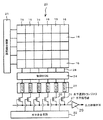
図1は本発明の実施の形態における固体撮像装置の具体例を示す平面図であり、CMOSイメージセンサの例を示している。また、図2は図1に示す固体撮像装置の画素内の回路構成を示す回路図である。
また、図3は本実施の形態による固体撮像装置の信号処理回路内でオプティカルブラック(OB)信号を目標値に補正するためのデジタルクランプ補正回路の構成例を示すブロック図である。
なお、以下の実施の形態はCMOSイメージセンサを中心に説明するが、本発明はCCDイメージセンサにも同様に適用できるものである。
FIG. 1 is a plan view showing a specific example of a solid-state imaging device according to an embodiment of the present invention, and shows an example of a CMOS image sensor. FIG. 2 is a circuit diagram showing a circuit configuration in a pixel of the solid-state imaging device shown in FIG.
FIG. 3 is a block diagram showing a configuration example of a digital clamp correction circuit for correcting an optical black (OB) signal to a target value in the signal processing circuit of the solid-state imaging device according to the present embodiment.
Although the following embodiments will be described centering on a CMOS image sensor, the present invention can be similarly applied to a CCD image sensor.
本実施の形態による固体撮像装置は、図1に示すように、2次元方向に配置された複数の画素16によって撮像領域を構成する画素アレイ部20と、画素アレイ部20の各画素を垂直方向に走査して画素信号の読み出し動作を制御する垂直走査回路21と、画素アレイ部20の各画素列(カラム)から導かれた垂直信号線28を制御する負荷MOSトランジスタ回路24と、画素アレイ部20の各画素列から読み出された画素信号を取り込み、相関二重サンプリング処理によるノイズ除去を行うCDS回路25と、CDS回路25の画素信号を水平信号線27に出力する水平選択トランジスタ回路26と、水平選択トランジスタ回路26を水平方向に順次選択して画素信号の出力を制御する水平走査回路22とを有する。そして、水平信号線27に出力された画素信号はバッファアンプ29を介して後段の回路に伝送される。
As shown in FIG. 1, the solid-state imaging device according to the present embodiment includes a
また、各画素16は、図2に示すように、入射した光を光電変換するフォトダイオード(PD)1と、光電変換された電気信号を転送パルス(ΦTRG)に基づいてフローティングデフュージョン(FD)部3に転送するトランジスタ(TG)12と、リセットパルス(ΦRST)に基づいてFD部3の電位を電源電圧VDDにリセットするリセットトランジスタ(RST)14、FD部3の電位変動を電圧信号または電流信号に変換する増幅トランジスタ(AMP)13と、選択信号(ΦSEL)に基づいて増幅トランジスタ13の出力を垂直信号線28に接続する選択トランジスタ15とを有する。
したがって、画素16の近傍には、垂直方向に垂直信号線28や電源線23等が配線され、水平方向に読み出し線17、リセット線18、選択線19等が配線されている。
Further, as shown in FIG. 2, each
Therefore, in the vicinity of the
次に、図3を用いて本実施の形態によるデジタルクランプ補正回路の構成について説明する。図3に示すデジタルクランプ補正回路は、例えばCDS回路の下流(図1の例ではバッファアンプ29の後段)に設けられており、さらに下流の信号処理回路(後述するDSP)にクランプ補正した画像信号を供給するものである。
CDS回路では、画素アレイ部から出力される画素信号について、リセットレベルのサンプリング値と信号レベルのサンプリング値との差分演算を行い、画素固有ノイズを除去した画像信号を出力するものであり、その画像信号が後段のAGC等によってオプティカルブラック(OB)に基づくブラックレベル等の直流値が付加される。
そこで本例のクランプ補正回路では、このような画像信号に含まれるブラックレベルを補正し、最適化した画像信号を後段の信号処理回路(DSP)に出力する。
Next, the configuration of the digital clamp correction circuit according to the present embodiment will be described with reference to FIG. The digital clamp correction circuit shown in FIG. 3 is provided, for example, downstream of the CDS circuit (after the
The CDS circuit performs a difference operation between a reset level sampling value and a signal level sampling value for a pixel signal output from the pixel array unit, and outputs an image signal from which pixel-specific noise is removed. A direct current value such as a black level based on optical black (OB) is added to the signal by AGC or the like at a later stage.
Therefore, in the clamp correction circuit of this example, the black level included in such an image signal is corrected, and the optimized image signal is output to the subsequent signal processing circuit (DSP).
図3に示すように、本例のクランプ補正回路は、オートゲインコントロール+サンプルホールド(AGC+S/H)回路101、アナログ/デジタル(A/D)コンバータ102、補正値生成部103、及び演算器104を有する。なお、この固体撮像装置で扱うデジタル画像信号はNビット(すなわち、最大2n)のデータであるものとする。
AGC+S/H回路101では、イメージセンサ(例えばバッファアンプ29)から出力されるアナログ画像信号(以下、センサ信号という)111に対してゲインコントロールを行い、所定のタイミングでサンプリングした信号をホールドする回路である。このAGC+S/H回路101において、CDS回路で生成された差分信号に、所定のリファレンス値(通常はオプティカルブラック値に基づく値(ブラックレベル))が付加された直流のセンサ信号112として出力される。
As shown in FIG. 3, the clamp correction circuit of this example includes an auto gain control + sample hold (AGC + S / H)
The AGC + S /
A/Dコンバータ102では、このようにAGC+S/H回路101でサンプルホールドされたアナログセンサ信号112を量子化し、デジタルセンサ信号112を生成する回路である。そして本例では、この量子化の際に、画像信号に与えられるNビットに補正用の1ビット(すなわち、M=1)を追加したN+1ビットの量子化を行い、N+1ビットのデジタル画像データ113を出力する。例えば、本来の画像データとして10ビット必要な場合には、11ビットで量子化する。
補正値生成部103では、A/Dコンバータ102で出力されたN+1ビットのデジタル画像データ113を入力し、このデジタル画像データ113に含まれるリファレンス値(本例ではブラックレベル)を補正するための補正値114を算出する。例えばCMOSイメージセンサの場合、カラム毎にブラックレベルのバラツキを有することから、このバラツキの補正やブラックレベル自体を適切なクランプ値に補正するための補正値を算出し、演算器104に出力する。
演算器104では、A/Dコンバータ102で出力されたN+1ビットのデジタル画像データ113と、補正値生成部103によって生成された補正値114を入力し、補正値114に基づいて、デジタル画像データ113に含まれるリファレンス値(本例ではブラックレベル)を補正する演算を行い、クランプ補正したNビットの画像データ115として出力する。
The A /
The correction
The
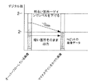
図4は図3に示すクランプ補正回路における各信号の状態を示す説明図である。
まず、A/Dコンバータ102で補正用の1ビットを追加した状態でA/D変換を行うことにより、N+1ビット(2n+1)のデジタル画像データ113を生成する。なお、ブラックレベルは量子化後の値が2nより下になっていれば十分である。
補正値生成部103では、そのブラックレベルを用いてランダムノイズやチャネル間段差、フレーム段差を補正した値にオフセットレベルを考慮した値(これらの値を総称して目標値という)を補正値114として算出する。
そして、演算器104では、この補正値114をデジタル画像データ113から引くことにより、Nビットの出力データ115を得る。
FIG. 4 is an explanatory diagram showing the state of each signal in the clamp correction circuit shown in FIG.
First,
In the correction
The
この図4から明らかなように、元の入力に含まれる画像信号のダイナミックレンジを削ることなく、出力データがブラックレベルをクランプした状態で出力される。なお、この出力データにおいて、Nビットを超える領域Aに入ってしまったデータは、明らかにオーバーフローしたデータであることから、全て1を出力することになる。
本実施の形態を適用した結果、ダイナミックレンジを無駄にすることなく、デジタルクランプ回路の構成のみで、変動やばらつきを含むオプティカルブラックの適正なクランプ補正を実現することが可能となる。
また、アナログのフィードバック補正回路が不要となることから、A/D変換前のノイズに厳しい状態のアナログ信号に対してノイズ等を印加を防ぐことができる。
また、フィードバックに使用するD/A等が不要になることから回路規模の小型化にも寄与することができる。
As is apparent from FIG. 4, the output data is output with the black level clamped without reducing the dynamic range of the image signal included in the original input. In this output data, the data that has entered the region A exceeding N bits is obviously overflowed data, so all 1s are output.
As a result of applying the present embodiment, it is possible to realize appropriate clamp correction of optical black including fluctuations and variations only with the configuration of the digital clamp circuit without wasting the dynamic range.
Further, since an analog feedback correction circuit is not required, it is possible to prevent application of noise or the like to an analog signal that is severely affected by noise before A / D conversion.
In addition, since the D / A and the like used for feedback are not necessary, it is possible to contribute to a reduction in circuit scale.
次に、本実施の形態を応用した他の動作例について説明する。
上述のように本実施の形態では、出力データがNビットを超えた場合、それをオーバーフローデータとして全て1を出力するようにしていたが、このオーバーフローの部分について、以下のような動作例1〜3の処理を施すことにより、さらに高品位の出力を得ることが可能となる。
Next, another operation example to which this embodiment is applied will be described.
As described above, in the present embodiment, when the output data exceeds N bits, all 1s are output as overflow data. However, with respect to this overflow portion, the following operation examples 1 to 1 are performed. By performing the process 3, it becomes possible to obtain a higher quality output.
図5は他の動作例1における画像信号の状態を示す説明図である。
この動作例1は、通常のNビットではオーバーフローとして扱われてしまう部分について、デジタル的に負のゲインをかけることで、正常なデータとして扱うことができるようにしたものである。
通常のデジタルゲインは正方向を指すことが多いが、本例では補正用の1ビットを用いて通常は白とびする画像に対して負のゲインをかけても、ダイナミックレンジを損なうことなく、有効データとして再現できる。
具体的には、例えば演算器104の後段にデジタルゲインコントロール回路を付与し、クランプ補正の後に画像信号がNビットを超える領域Aに存在するデータに対し、そのオーバーフロー部分に1を挿入する代わりに、マイナスゲインをかけてNビットに収まるようにする。
FIG. 5 is an explanatory view showing the state of an image signal in another operation example 1. FIG.
In this operation example 1, a portion that is treated as an overflow with normal N bits can be treated as normal data by applying a negative gain digitally.
Normal digital gain often points in the positive direction, but in this example, even if a negative gain is applied to an image that is normally overexposure using one bit for correction, it is effective without impairing the dynamic range. Can be reproduced as data.
Specifically, for example, a digital gain control circuit is provided at the subsequent stage of the
図6は他の動作例2における画像信号の状態を示す説明図である。
この動作例2は、画像が明るいことを想定して、暗い部分の分解能を削り、高輝度部分のビット分解能を維持したまま、オーバーフローしたデータをシフトさせることで、有効データとして出力するものである。
すなわち、何等かの方法で輝度レベルの指定を行い、その指定レベル以下の低輝度領域をクランプ補正したブラックレベルに再度クランプして除去することにより、高輝度領域のデータをシフトし、Nビットを超える領域Aに存在するデータを有効データとして再現できる。
この場合、演算器104にレベルシフト演算を制御する手段を付加して行う。また、シフトするレベルを指定する方法としては、オーバーフローした画像信号から判定する方法や、予め設定した固定レベルを用いる方法等があり、被写体の状況やシステムの用途等に応じて種々選択が可能である。
FIG. 6 is an explanatory diagram showing the state of the image signal in the second operation example.
In this operation example 2, assuming that the image is bright, the resolution of the dark part is reduced, and the overflowed data is shifted while maintaining the bit resolution of the high-luminance part, so that it is output as valid data. .
That is, the brightness level is specified by any method, and the low brightness area below the specified level is re-clamped to the clamped black level and removed, thereby shifting the data of the high brightness area and setting the N bit. Data existing in the region A exceeding can be reproduced as valid data.
In this case, the
図7は他の動作例3における画像信号の状態を示す説明図である。
この動作例3は、暗い領域のビット分解能を維持したまま、オーバーフローしてしまった高輝度の箇所のみにマイナスゲインをかけることで通常使用のダイナミックレンジを越えた高ダイナミックレンジの画像を実現するものである。この場合、高輝度領域のレベルを指定して、そのレベル以上のデータにマイナスゲインをかけることになる。
さらに、図6に示した低輝度領域をレベルシフトする方法と、図7に示した高輝度領域にマイナスゲインをかける方法とを組み合わせるようにしても良い。この場合、シフトする低輝度領域のレベルと、マイナスゲインをかける高輝度領域のレベルの2つのレベルを指定して演算処理を行えば、さらに最適化した高ダイナミックレンジの画像を実現することができる。
FIG. 7 is an explanatory diagram showing the state of an image signal in another operation example 3.
This operation example 3 realizes an image with a high dynamic range that exceeds the dynamic range of normal use by applying a minus gain only to the high-luminance portion that has overflowed while maintaining the bit resolution of the dark region. It is. In this case, the level of the high luminance area is designated, and minus gain is applied to data above that level.
Furthermore, the method of level shifting the low luminance region shown in FIG. 6 and the method of applying a minus gain to the high luminance region shown in FIG. 7 may be combined. In this case, an image with a further optimized high dynamic range can be realized by performing calculation processing by designating two levels: a low luminance region level to be shifted and a high luminance region level to which minus gain is applied. .
以上説明したように、本実施の形態によれば、デジタル回路のみでクランプ補正回路を構成することにより、アナログフィードバック回路を削除でき、回路の小型化、及びアナログ回路によるノイズの増大を防ぐことができる。
また、量子化の際に補正用のMビットを追加することにより、デジタルクランプによるダイナミックレンジの低下を防ぐことができる。
さらに、デジタル的にマイナスゲインをかける場合でも、ダイナミックレンジを減らさずに行うことが可能なことから、高輝度領域のオーバーフロー状態を有効データとして扱うことが可能となる。
また、低輝度領域をクランプして高輝度の分解能を維持してもダイナミックレンジを損なうことなくデータを出力することができる。
さらに高輝度領域のある範囲のみマイナスゲインをかけることにより、低輝度の分解能を維持したまま高輝度のオーバーフローを防ぐことが可能となる。
As described above, according to the present embodiment, the analog feedback circuit can be eliminated by configuring the clamp correction circuit only with the digital circuit, and the circuit can be reduced in size and the increase in noise due to the analog circuit can be prevented. it can.
Further, by adding M bits for correction at the time of quantization, it is possible to prevent a decrease in dynamic range due to digital clamping.
Furthermore, even when a minus gain is applied digitally, it can be performed without reducing the dynamic range, so that the overflow state of the high luminance region can be handled as valid data.
Further, even if the low luminance region is clamped and the high luminance resolution is maintained, data can be output without impairing the dynamic range.
Further, by applying a minus gain only to a certain range of the high luminance region, it is possible to prevent the high luminance overflow while maintaining the low luminance resolution.
なお、以上の実施の形態では、オプティカルブラック値をクランプ補正するクランプ補正回路について説明したが、本発明は他のクランプ補正回路にも適用できるものである。
また、以上は本発明をCMOSイメージセンサについて適用した場合を説明したが、本発明は必ずしもCMOSイメージセンサに限定されず、クランプ補正やA/D変換を行う各種の固体撮像装置に広く適用できるものである。
In the above embodiment, the clamp correction circuit that clamps and corrects the optical black value has been described. However, the present invention can also be applied to other clamp correction circuits.
Further, the case where the present invention is applied to a CMOS image sensor has been described above, but the present invention is not necessarily limited to a CMOS image sensor, and can be widely applied to various solid-state imaging devices that perform clamp correction and A / D conversion. It is.
また、固体撮像装置は1チップ上にイメージセンサを構成したものに限らず、イメージセンサを搭載した撮像部と信号処理部や光学系とを別の部品として構成し、これらをまとめてパッケージ化した構成であってもよく、さらに、制御部や操作部と一体化され、カメラシステムや携帯電話器に利用される装置であってもよい。すなわち、本発明では、単体のイメージセンサを固体撮像装置と言い、他の機能部品(例えば通信モジュールや表示モジュール)と組み合わせたものを撮像装置と言うものとし、いずれも本発明の範囲とするものである。
そして、図3に示すクランプ補正回路は、固体撮像装置側に設けても良いし、撮像装置側に設けられる信号処理回路内に設けても良い。
In addition, the solid-state imaging device is not limited to an image sensor configured on one chip, and an imaging unit on which the image sensor is mounted, a signal processing unit, and an optical system are configured as separate parts, and these are packaged together. It may be a configuration, and may be an apparatus that is integrated with a control unit or an operation unit and used for a camera system or a mobile phone. That is, in the present invention, a single image sensor is referred to as a solid-state imaging device, and a combination of other functional components (for example, a communication module and a display module) is referred to as an imaging device, both of which are within the scope of the present invention. It is.
The clamp correction circuit shown in FIG. 3 may be provided on the solid-state imaging device side or in a signal processing circuit provided on the imaging device side.
以下、本発明を適用した撮像装置の具体例を説明する。
図8は本例のCMOSイメージセンサを用いたカメラ装置の構成例を示すブロック図である。
図において、撮像部310は、例えば図1に示したCMOSイメージセンサを用いて被写体の撮像を行い、撮像信号をメイン基板に搭載されたシステムコントロール部320に出力する。すなわち、撮像部310では、上述したCMOSイメージセンサの出力信号に対し、AGC(自動利得制御)、OB(オプティカルブラック)クランプ、CDS(相関二重サンプリング)といった処理を行い、その後段で、図3に示したクランプ補正回路により、クランプ補正したデジタル撮像信号を生成し、システムコントロール部320に出力する。
なお、本例では、撮像部310側にクランプ補正回路を設けた例について示しているが、撮像部310からアナログ撮像信号をシステムコントロール部320に送り、システムコントロール部320側でクランプ補正回路によりデジタル信号を生成するような構成であってもよい。また、撮像部310内での処理も種々の方法があり、特に限定しないことは勿論である。
Hereinafter, a specific example of an imaging apparatus to which the present invention is applied will be described.
FIG. 8 is a block diagram showing a configuration example of a camera device using the CMOS image sensor of this example.
In the figure, an
In this example, an example in which a clamp correction circuit is provided on the
また、撮像光学系300は、鏡筒内に配置されたズームレンズ301や絞り機構302等を含み、CMOSイメージセンサの受光部に被写体像を結像させるものであり、システムコントロール部320の指示に基づく駆動制御部330の制御により、各部を機械的に駆動してオートフォーカス等の制御が行われる。
The imaging
また、システムコントロール部320には、CPU321、ROM322、RAM323、DSP324、外部インターフェース325等が設けられている。
CPU321は、ROM322及びRAM323を用いて本カメラ装置の各部に指示を送り、システム全体の制御を行う。
DSP324は、撮像部310からの撮像信号に対して各種の信号処理を行うことにより、所定のフォーマットによる静止画または動画の映像信号(例えばYUV信号等)を生成する。
外部インターフェース325には、各種エンコーダやD/A変換器が設けられ、システムコントロール部320に接続される外部要素(本例では、ディスプレイ360、メモリ媒体340、操作パネル部350)との間で、各種制御信号やデータをやり取りする。
The system control unit 320 includes a
The
The
The
ディスプレイ360は、本カメラ装置に組み込まれた例えば液晶パネル等の小型表示器であり、撮像した画像を表示する。なお、このようなカメラ装置に組み込まれた小型表示器に加えて、外部の大型表示装置に画像データを伝送し、表示できる構成とすることも勿論可能である。
メモリ媒体340は、例えば各種メモリカード等に撮影された画像を適宜保存しておけるものであり、例えばメモリ媒体コントローラ341に対してメモリ媒体を交換可能なものとなっている。メモリ媒体340としては、各種メモリカードの他に、磁気や光を用いたディスク媒体等を用いることができる。
操作パネル部350は、本カメラ装置で撮影作業を行うに際し、ユーザが各種の指示を行うための入力キーを設けたものであり、CPU321は、この操作パネル部350からの入力信号を監視し、その入力内容に基づいて各種の動作制御を実行する。
The
The
The
このようなカメラ装置に、本発明を適用することにより、種々の被写体に関し、高ダイナミックレンジの撮影を行うことができる。なお、以上の構成において、システムの構成要素となる単位デバイスや単位モジュールの組み合わせ方、セットの規模等については、製品化の実情等に基づいて適宜選択することが可能であり、本発明の撮像装置は、種々の変形を幅広く含むものとする。 By applying the present invention to such a camera device, it is possible to perform shooting with a high dynamic range for various subjects. In the above configuration, unit devices and unit modules as system components, a combination method, a set size, and the like can be appropriately selected based on the actual state of commercialization and the like. The device shall include a wide variety of variations.
また、本発明の固体撮像装置及び撮像装置において、撮像対象(被写体)としては、人や景色等の一般的な映像に限らず、偽札検出器や指紋検出器等の特殊な微細画像パターンの撮像にも適用できるものである。この場合の装置構成としては、図8に示した一般的なカメラ装置ではなく、さらに特殊な撮像光学系やパターン解析を含む信号処理系を含むことになり、この場合にも本発明の作用効果を十分発揮して、精密な画像検出を実現することが可能となる。
さらに、遠隔医療や防犯監視、個人認証等のように遠隔システムを構成する場合には、上述のようにネットワークと接続した通信モジュールを含む装置構成とすることも可能であり、幅広い応用が実現可能である。
In the solid-state imaging device and imaging device of the present invention, the imaging target (subject) is not limited to a general image such as a person or a landscape, but a special fine image pattern such as a counterfeit bill detector or a fingerprint detector. It can also be applied to. The apparatus configuration in this case is not the general camera apparatus shown in FIG. 8, but includes a signal processing system including a special imaging optical system and pattern analysis. This makes it possible to realize accurate image detection.
Furthermore, when configuring a remote system such as telemedicine, security monitoring, personal authentication, etc., it is also possible to configure the device configuration including a communication module connected to the network as described above, and a wide range of applications can be realized. It is.
1……フォトダイオード、12……転送トランジスタ、13……増幅トランジスタ、14……リセットトランジスタ、15……選択トランジスタ、16……画素、20……画素アレイ部、25……CDS回路、101……AGC+S/H回路、102……A/Dコンバータ、103……補正値生成部、104……演算器。
DESCRIPTION OF
Claims (12)
前記画素アレイ部から出力される画素信号を出力画像信号に変換する信号変換回路と、
前記信号変換回路の出力画像信号に含まれるクランプレベルを補正するクランプ補正回路と、を有し、
前記クランプ補正回路は、
前記出力画像信号のA/D変換を行うとともに、このA/D変換の際に前記出力画像信号に割り当てられるビット数Nに補正用のMビットを追加したN+Mビットのデジタルデータを生成して出力するA/D変換手段と、
前記A/D変換手段によって出力されたN+Mビットのデジタルデータと、ランダムノイズやチャネル間段差、フレーム段差を補正した値にオフセットレベルを考慮した値とに基づいて補正値を決定する補正値生成手段と、
前記A/D変換手段によって出力されたN+Mビットのデジタルデータと、前記補正値生成手段によって出力された補正値によって補正演算を行い、該補正演算後の下位Nビットのクランプ補正データを生成する演算手段と、
を有することを特徴とする固体撮像装置。 A pixel array unit composed of a plurality of pixels each having a photoelectric conversion unit;
A signal conversion circuit for converting a pixel signal output from the pixel array unit into an output image signal;
A clamp correction circuit for correcting a clamp level included in the output image signal of the signal conversion circuit,
The clamp correction circuit includes:
A / D conversion of the output image signal is performed, and N + M-bit digital data obtained by adding M bits for correction to the number N of bits allocated to the output image signal at the time of the A / D conversion is generated and output. A / D conversion means for
Correction value generation means for determining a correction value based on N + M-bit digital data output by the A / D conversion means and a value in which an offset level is taken into account after correcting random noise, a step difference between channels, and a frame step difference. When,
An operation for performing a correction operation using the N + M bit digital data output by the A / D conversion unit and the correction value output by the correction value generation unit, and generating clamp correction data of lower N bits after the correction operation Means,
A solid-state imaging device.
前記固体撮像装置の受光部に被写体像を結像させる撮像光学系と、
前記撮像光学系を駆動する駆動制御部と、
前記固体撮像装置からの出力信号を信号処理し、撮像信号を生成する信号処理部と、
前記信号処理部によって生成された撮像信号を記録する記録部と、
前記信号処理部によって生成された撮像信号を出力する出力部と、撮像動作を制御するための各種信号を入力する操作部と、を有し、
前記固体撮像装置は、
それぞれ光電変換部を有する複数の画素より構成される画素アレイ部と、
前記画素アレイ部から出力される画素信号を出力画像信号に変換する信号変換回路と、
前記信号変換回路の出力画像信号に含まれるクランプレベルを補正するクランプ補正回路と、を有し、
前記クランプ補正回路は、
前記出力画像信号のA/D変換を行うとともに、このA/D変換の際に前記出力画像信号に割り当てられるビット数Nに補正用のMビットを追加したN+Mビットのデジタルデータを生成して出力するA/D変換手段と、
前記A/D変換手段によって出力されたN+Mビットのデジタルデータと、ランダムノイズやチャネル間段差、フレーム段差を補正した値にオフセットレベルを考慮した値とに基づいて補正値を決定する補正値生成手段と、
前記A/D変換手段によって出力されたN+Mビットのデジタルデータと、前記補正値生成手段によって出力された補正値によって補正演算を行い、該補正演算後の下位Nビットのクランプ補正データを生成する演算手段と、
を有することを特徴とする撮像装置。 A solid-state imaging device for imaging a subject;
An imaging optical system that forms a subject image on a light receiving unit of the solid-state imaging device;
A drive controller for driving the imaging optical system;
A signal processing unit that processes an output signal from the solid-state imaging device and generates an imaging signal;
A recording unit for recording the imaging signal generated by the signal processing unit;
An output unit that outputs an imaging signal generated by the signal processing unit, and an operation unit that inputs various signals for controlling an imaging operation,
The solid-state imaging device
A pixel array unit composed of a plurality of pixels each having a photoelectric conversion unit;
A signal conversion circuit for converting a pixel signal output from the pixel array unit into an output image signal;
A clamp correction circuit for correcting a clamp level included in the output image signal of the signal conversion circuit,
The clamp correction circuit includes:
A / D conversion of the output image signal is performed, and N + M-bit digital data obtained by adding M bits for correction to the number N of bits allocated to the output image signal at the time of the A / D conversion is generated and output. A / D conversion means for
Correction value generation means for determining a correction value based on N + M-bit digital data output by the A / D conversion means and a value in which an offset level is taken into account after correcting random noise, a step difference between channels, and a frame step difference. When,
An operation for performing a correction operation using the N + M bit digital data output by the A / D conversion unit and the correction value output by the correction value generation unit, and generating clamp correction data of lower N bits after the correction operation Means,
An imaging device comprising:
Priority Applications (2)
| Application Number | Priority Date | Filing Date | Title |
|---|---|---|---|
| JP2006288689A JP4931546B2 (en) | 2006-10-24 | 2006-10-24 | Solid-state imaging device and imaging device |
| US11/876,905 US8269863B2 (en) | 2006-10-24 | 2007-10-23 | Solid-state image pickup device and image pickup apparatus |
Applications Claiming Priority (1)
| Application Number | Priority Date | Filing Date | Title |
|---|---|---|---|
| JP2006288689A JP4931546B2 (en) | 2006-10-24 | 2006-10-24 | Solid-state imaging device and imaging device |
Publications (3)
| Publication Number | Publication Date |
|---|---|
| JP2008109264A JP2008109264A (en) | 2008-05-08 |
| JP2008109264A5 JP2008109264A5 (en) | 2009-01-15 |
| JP4931546B2 true JP4931546B2 (en) | 2012-05-16 |
Family
ID=39317512
Family Applications (1)
| Application Number | Title | Priority Date | Filing Date |
|---|---|---|---|
| JP2006288689A Expired - Fee Related JP4931546B2 (en) | 2006-10-24 | 2006-10-24 | Solid-state imaging device and imaging device |
Country Status (2)
| Country | Link |
|---|---|
| US (1) | US8269863B2 (en) |
| JP (1) | JP4931546B2 (en) |
Families Citing this family (6)
| Publication number | Priority date | Publication date | Assignee | Title |
|---|---|---|---|---|
| TW201001334A (en) * | 2008-06-20 | 2010-01-01 | Altek Corp | Adjustment method of color tone for digital image and electronic apparatus thereof |
| WO2010030574A1 (en) * | 2008-09-11 | 2010-03-18 | Zoran Corporation | Method and apparatus for post noise reduction black level correction |
| JP5672853B2 (en) * | 2010-08-25 | 2015-02-18 | ソニー株式会社 | Radiation imaging device |
| JP2019153946A (en) | 2018-03-05 | 2019-09-12 | ソニーセミコンダクタソリューションズ株式会社 | Imaging element and electronic apparatus |
| US10885655B2 (en) * | 2018-08-22 | 2021-01-05 | Kayak Software Corporation | Systems and methods for object measurement |
| CN110365922B (en) * | 2019-07-03 | 2021-09-14 | 成都微光集电科技有限公司 | Black level correction method of image sensor |
Family Cites Families (19)
| Publication number | Priority date | Publication date | Assignee | Title |
|---|---|---|---|---|
| JPS6437179A (en) * | 1987-08-01 | 1989-02-07 | Sharp Kk | Digital video camera |
| US4920428A (en) * | 1988-07-08 | 1990-04-24 | Xerox Corporation | Offset, gain and bad pixel correction in electronic scanning arrays |
| JP3143117B2 (en) * | 1990-09-25 | 2001-03-07 | キヤノン株式会社 | Signal processing device |
| JPH07221980A (en) * | 1994-02-08 | 1995-08-18 | Ricoh Co Ltd | Image reader |
| JP3363648B2 (en) * | 1995-03-27 | 2003-01-08 | キヤノン株式会社 | Imaging device |
| JPH09205587A (en) * | 1996-01-29 | 1997-08-05 | Canon Inc | Image pickup device |
| JP3834130B2 (en) * | 1996-07-19 | 2006-10-18 | 株式会社リコー | Digital camera |
| JP3825850B2 (en) | 1996-12-16 | 2006-09-27 | キヤノン株式会社 | Imaging device |
| JP2000156822A (en) * | 1998-11-19 | 2000-06-06 | Sony Corp | Clamp circuit |
| JP4454750B2 (en) * | 1999-12-28 | 2010-04-21 | 日本バーブラウン株式会社 | Front-end signal processing method and apparatus for image sensor |
| JP4398082B2 (en) * | 2000-11-10 | 2010-01-13 | 富士フイルム株式会社 | Solid-state imaging device and solid-state imaging apparatus |
| JP2003298953A (en) * | 2002-03-29 | 2003-10-17 | Seiko Epson Corp | Image processing apparatus and image processing method |
| JP4328508B2 (en) | 2002-10-04 | 2009-09-09 | Necエンジニアリング株式会社 | Image processing device |
| JP4218357B2 (en) * | 2003-01-31 | 2009-02-04 | セイコーエプソン株式会社 | Digital clamp circuit and digital clamp processing method |
| JP4333290B2 (en) | 2003-09-04 | 2009-09-16 | 株式会社ニコン | Black level correction device and electronic camera |
| JP4574144B2 (en) * | 2003-09-09 | 2010-11-04 | キヤノン株式会社 | DIGITAL CLAMP DEVICE, DIGITAL CLAMP METHOD, PROGRAM, AND STORAGE MEDIUM |
| JP4345004B2 (en) * | 2004-04-23 | 2009-10-14 | ソニー株式会社 | Optical black level adjustment circuit |
| JP2006086971A (en) * | 2004-09-17 | 2006-03-30 | Canon Inc | Imaging device |
| JP2007028339A (en) * | 2005-07-19 | 2007-02-01 | Canon Inc | Imaging apparatus, control method and program thereof and storage medium |
-
2006
- 2006-10-24 JP JP2006288689A patent/JP4931546B2/en not_active Expired - Fee Related
-
2007
- 2007-10-23 US US11/876,905 patent/US8269863B2/en not_active Expired - Fee Related
Also Published As
| Publication number | Publication date |
|---|---|
| US8269863B2 (en) | 2012-09-18 |
| JP2008109264A (en) | 2008-05-08 |
| US20080094489A1 (en) | 2008-04-24 |
Similar Documents
| Publication | Publication Date | Title |
|---|---|---|
| JP5082528B2 (en) | Solid-state imaging device and imaging device | |
| JP4311181B2 (en) | Semiconductor device control method, signal processing method, semiconductor device, and electronic apparatus | |
| JP5247007B2 (en) | Imaging apparatus and imaging system | |
| US7907193B2 (en) | Image capturing apparatus | |
| US9544518B2 (en) | Image pickup apparatus and image pickup system with ad converter outputting image data at first resolution in a case where pixel signals are not higher than threshold level and at second resolution in a case where pixel signals are higher than threshold level | |
| US20060237721A1 (en) | Solid-state image pickup device, driving method for solid-state image pickup device, and image pickup apparatus | |
| KR101939402B1 (en) | Solid-state imaging device and driving method thereof, and electronic apparatus using the same | |
| JP2008124527A (en) | Solid-state imaging device and imaging apparatus | |
| JP4931546B2 (en) | Solid-state imaging device and imaging device | |
| JP2020178186A (en) | Image pickup apparatus and control method thereof | |
| JP2008109264A5 (en) | ||
| US9407842B2 (en) | Image pickup apparatus and image pickup method for preventing degradation of image quality | |
| JP2008187565A (en) | Solid-state imaging apparatus and imaging apparatus | |
| JP2009089087A (en) | Solid-state image pickup apparatus and image pickup apparatus | |
| JP4916271B2 (en) | Solid-state imaging device and electronic information device | |
| JP2005109993A (en) | Photographing apparatus | |
| JP5627728B2 (en) | Imaging apparatus and imaging system | |
| US7489356B2 (en) | Image pickup apparatus | |
| JP5222029B2 (en) | IMAGING DEVICE, IMAGING SYSTEM, AND IMAGING DEVICE CONTROL METHOD | |
| US7999871B2 (en) | Solid-state imaging apparatus, and video camera and digital still camera using the same | |
| JP2007143067A (en) | Image sensing device and image sensing system | |
| JP2008236634A (en) | Solid-state image pickup device and imaging apparatus | |
| JP2006197229A (en) | Image pickup device and camera | |
| JP4872502B2 (en) | Imaging apparatus and clamping method thereof | |
| JP2020057883A (en) | Imaging apparatus |
Legal Events
| Date | Code | Title | Description |
|---|---|---|---|
| A621 | Written request for application examination |
Free format text: JAPANESE INTERMEDIATE CODE: A621 Effective date: 20080313 |
|
| A977 | Report on retrieval |
Free format text: JAPANESE INTERMEDIATE CODE: A971007 Effective date: 20080828 |
|
| A521 | Request for written amendment filed |
Free format text: JAPANESE INTERMEDIATE CODE: A523 Effective date: 20081119 |
|
| A131 | Notification of reasons for refusal |
Free format text: JAPANESE INTERMEDIATE CODE: A131 Effective date: 20090707 |
|
| RD02 | Notification of acceptance of power of attorney |
Free format text: JAPANESE INTERMEDIATE CODE: A7422 Effective date: 20090817 |
|
| A521 | Request for written amendment filed |
Free format text: JAPANESE INTERMEDIATE CODE: A523 Effective date: 20090904 |
|
| RD04 | Notification of resignation of power of attorney |
Free format text: JAPANESE INTERMEDIATE CODE: A7424 Effective date: 20091015 |
|
| A02 | Decision of refusal |
Free format text: JAPANESE INTERMEDIATE CODE: A02 Effective date: 20100406 |
|
| A521 | Request for written amendment filed |
Free format text: JAPANESE INTERMEDIATE CODE: A523 Effective date: 20100705 |
|
| A911 | Transfer to examiner for re-examination before appeal (zenchi) |
Free format text: JAPANESE INTERMEDIATE CODE: A911 Effective date: 20100714 |
|
| A912 | Re-examination (zenchi) completed and case transferred to appeal board |
Free format text: JAPANESE INTERMEDIATE CODE: A912 Effective date: 20101228 |
|
| A01 | Written decision to grant a patent or to grant a registration (utility model) |
Free format text: JAPANESE INTERMEDIATE CODE: A01 |
|
| A61 | First payment of annual fees (during grant procedure) |
Free format text: JAPANESE INTERMEDIATE CODE: A61 Effective date: 20120214 |
|
| R150 | Certificate of patent or registration of utility model |
Free format text: JAPANESE INTERMEDIATE CODE: R150 |
|
| FPAY | Renewal fee payment (event date is renewal date of database) |
Free format text: PAYMENT UNTIL: 20150224 Year of fee payment: 3 |
|
| R250 | Receipt of annual fees |
Free format text: JAPANESE INTERMEDIATE CODE: R250 |
|
| LAPS | Cancellation because of no payment of annual fees |