JP4928969B2 - Endoscope bending retention mechanism - Google Patents
Endoscope bending retention mechanism Download PDFInfo
- Publication number
- JP4928969B2 JP4928969B2 JP2007028708A JP2007028708A JP4928969B2 JP 4928969 B2 JP4928969 B2 JP 4928969B2 JP 2007028708 A JP2007028708 A JP 2007028708A JP 2007028708 A JP2007028708 A JP 2007028708A JP 4928969 B2 JP4928969 B2 JP 4928969B2
- Authority
- JP
- Japan
- Prior art keywords
- bending
- leaf spring
- pressure contact
- metal disk
- endoscope
- Prior art date
- Legal status (The legal status is an assumption and is not a legal conclusion. Google has not performed a legal analysis and makes no representation as to the accuracy of the status listed.)
- Active
Links
- 238000005452 bending Methods 0.000 title claims description 136
- 230000007246 mechanism Effects 0.000 title claims description 74
- 230000014759 maintenance of location Effects 0.000 title claims 2
- 239000002184 metal Substances 0.000 claims description 63
- 229910052751 metal Inorganic materials 0.000 claims description 63
- 210000000078 claw Anatomy 0.000 claims description 28
- 230000002093 peripheral effect Effects 0.000 claims description 13
- 239000000463 material Substances 0.000 claims description 11
- 230000008531 maintenance mechanism Effects 0.000 claims description 8
- 238000003780 insertion Methods 0.000 description 7
- 230000037431 insertion Effects 0.000 description 7
- 239000007799 cork Substances 0.000 description 5
- 238000000034 method Methods 0.000 description 4
- 230000006866 deterioration Effects 0.000 description 3
- 230000004048 modification Effects 0.000 description 3
- 238000012986 modification Methods 0.000 description 3
- 239000007779 soft material Substances 0.000 description 3
- 230000007423 decrease Effects 0.000 description 2
- 150000002739 metals Chemical class 0.000 description 2
- 229910001220 stainless steel Inorganic materials 0.000 description 2
- 239000010935 stainless steel Substances 0.000 description 2
- 230000003068 static effect Effects 0.000 description 2
- 229910001369 Brass Inorganic materials 0.000 description 1
- 239000010951 brass Substances 0.000 description 1
- 230000005489 elastic deformation Effects 0.000 description 1
- NJPPVKZQTLUDBO-UHFFFAOYSA-N novaluron Chemical compound C1=C(Cl)C(OC(F)(F)C(OC(F)(F)F)F)=CC=C1NC(=O)NC(=O)C1=C(F)C=CC=C1F NJPPVKZQTLUDBO-UHFFFAOYSA-N 0.000 description 1
- 230000001105 regulatory effect Effects 0.000 description 1
- 230000001954 sterilising effect Effects 0.000 description 1
- 238000004659 sterilization and disinfection Methods 0.000 description 1
- 230000036962 time dependent Effects 0.000 description 1
Images


Classifications
-
- A—HUMAN NECESSITIES
- A61—MEDICAL OR VETERINARY SCIENCE; HYGIENE
- A61B—DIAGNOSIS; SURGERY; IDENTIFICATION
- A61B1/00—Instruments for performing medical examinations of the interior of cavities or tubes of the body by visual or photographical inspection, e.g. endoscopes; Illuminating arrangements therefor
- A61B1/005—Flexible endoscopes
- A61B1/0051—Flexible endoscopes with controlled bending of insertion part
- A61B1/0052—Constructional details of control elements, e.g. handles
Landscapes
- Health & Medical Sciences (AREA)
- Life Sciences & Earth Sciences (AREA)
- Surgery (AREA)
- Biomedical Technology (AREA)
- Medical Informatics (AREA)
- Optics & Photonics (AREA)
- Pathology (AREA)
- Radiology & Medical Imaging (AREA)
- Biophysics (AREA)
- Engineering & Computer Science (AREA)
- Physics & Mathematics (AREA)
- Heart & Thoracic Surgery (AREA)
- Nuclear Medicine, Radiotherapy & Molecular Imaging (AREA)
- Molecular Biology (AREA)
- Animal Behavior & Ethology (AREA)
- General Health & Medical Sciences (AREA)
- Public Health (AREA)
- Veterinary Medicine (AREA)
- Instruments For Viewing The Inside Of Hollow Bodies (AREA)
- Endoscopes (AREA)
Description
この発明は内視鏡の湾曲保持機構に関する。 The present invention relates to a bending holding mechanism of an endoscope.
内視鏡には一般に、挿入部の先端付近に設けられた湾曲部を遠隔操作により屈曲させるための湾曲操作機構が操作部に回転自在に配置され、内視鏡の挿入部先端を目標患部等に向けた状態を維持するために、湾曲操作機構の回転動作に摩擦抵抗を付与して湾曲操作機構を任意の回転位置で静止させるための湾曲保持機構が設けられている。 In general, a bending operation mechanism for bending a bending portion provided near the distal end of the insertion portion by remote control is rotatably disposed on the operation portion, and the distal end of the insertion portion of the endoscope is set as a target affected part or the like. In order to maintain the state of the bending operation mechanism, a bending holding mechanism is provided for applying frictional resistance to the rotation operation of the bending operation mechanism to make the bending operation mechanism stationary at an arbitrary rotation position.
そして、そのような従来の内視鏡の湾曲保持機構においては、湾曲操作機構の回転動作に摩擦抵抗を付与するための摩擦抵抗発生部材が、ゴム材又はコルク材等のような軟質の材料からなるドーナツ状の摩擦円盤とその摩擦円盤の全面に圧接される金属円盤とにより形成されていた(例えば、特許文献1、2)。
しかし、摩擦抵抗発生部材としてゴム材又はコルク材等のような軟質の材料からなる摩擦円盤が用いられていると、摩擦円盤を支持するために裏側にも第2の金属円盤等を配置する必要があり、さらに、摩擦円盤と金属円盤との間の摩擦抵抗を適切に設定するために、皿バネ等を設けるか或いは軟質の材料からなる摩擦円盤の肉厚を十分に厚く形成する必要がある。 However, when a friction disk made of a soft material such as a rubber material or a cork material is used as the frictional resistance generating member, it is necessary to arrange a second metal disk or the like on the back side in order to support the friction disk. Furthermore, in order to appropriately set the frictional resistance between the friction disk and the metal disk, it is necessary to provide a disc spring or the like or to make the friction disk made of a soft material sufficiently thick. .
その結果、従来の内視鏡の湾曲保持機構は厚みが大きくなってしまうため、湾曲保持機構を湾曲操作ノブ内の空間に配置すると湾曲操作ノブが大型になって操作性を損なったり、湾曲操作ノブ内に他の機構(例えば、一定以上の操作トルクが加えられた場合の安全確保のためのトルクリミット機構等)を組み込みたい時にそれが困難になってしまう場合等があった。 As a result, since the bending holding mechanism of the conventional endoscope becomes thick, if the bending holding mechanism is arranged in the space inside the bending operation knob, the bending operation knob becomes large and the operability is deteriorated. There are cases where it becomes difficult to incorporate another mechanism (for example, a torque limit mechanism for ensuring safety when an operation torque of a certain level or more is applied) into the knob.
また、ゴム材やコルク材等からなる摩擦円盤は精密な平面性が得られないため、金属円盤に対して外周寄りの部分が圧接する場合と内周寄りの部分が圧接する場合とがあり、金属円盤との圧接により発生する摩擦抵抗の大きさが相当にばらついてしまう。 In addition, since the friction disk made of rubber material or cork material cannot obtain precise flatness, there are cases where the outer peripheral part is pressed against the metal disk and the inner peripheral part is pressed. The magnitude of the frictional resistance generated by the pressure contact with the metal disk varies considerably.
また、ゴム材やコルク材等からなる摩擦円盤は熱に弱くて経時的な劣化も発生し易く、内視鏡使用後に高温高圧蒸気滅菌処理が繰り返されると、次第に所定の摩擦抵抗を得ることができなくなってしまう場合がある。 In addition, friction disks made of rubber, cork, etc. are vulnerable to heat and are subject to deterioration over time, and when high-temperature and high-pressure steam sterilization is repeated after use of an endoscope, a predetermined friction resistance can be gradually obtained. It may not be possible.
また、内視鏡の湾曲保持機構においては、湾曲操作機構を摩擦抵抗で任意の回転位置で静止させた状態からそのまま(即ち、摩擦抵抗付与を解除する操作をすることなく)湾曲操作をすれば湾曲操作を容易に行うことができて、その湾曲操作をやめれば他の回転位置において再び湾曲操作機構を静止させることができると操作性がよい。しかし、ゴム材やコルク材等は動摩擦力が安定せず静止摩擦力と比較して大きくなる場合が多いため、従来の装置では、摩擦抵抗付与を解除する操作をしないと湾曲操作が非常に重くなってしまい操作性が悪い。 Further, in the bending holding mechanism of the endoscope, if the bending operation mechanism is operated as it is from the state where the bending operation mechanism is stopped at an arbitrary rotational position with the frictional resistance (that is, without performing the operation for releasing the application of the frictional resistance). The bending operation can be easily performed, and if the bending operation is stopped, the bending operation mechanism can be stopped again at another rotational position, so that the operability is good. However, rubber materials and cork materials are often unstable compared to static friction force because the dynamic friction force is not stable, so in conventional devices, the bending operation is very heavy unless the operation to release the frictional resistance is performed. The operability is bad.
そこで本発明は、機構の厚みを薄く小型に構成することができ、その結果、湾曲操作ノブを小型化して操作性を向上させたり湾曲操作ノブ内に他の機構を組み込むことが可能になり、また、発生する摩擦抵抗の大きさにバラツキがなくて耐熱性や経時的な劣化の点でも優れた特性を有し、且つ優れた操作性を得ることができる内視鏡の湾曲保持機構を提供することを目的とする。 Therefore, the present invention can be configured with a small and thin mechanism, and as a result, the bending operation knob can be downsized to improve operability, or another mechanism can be incorporated into the bending operation knob. In addition, there is provided a bending mechanism for an endoscope that has excellent characteristics in terms of heat resistance and deterioration over time, has no variation in the magnitude of generated frictional resistance, and can obtain excellent operability. The purpose is to do.
上記の目的を達成するため、本発明の内視鏡の湾曲保持機構は、湾曲部を遠隔操作により屈曲させるために操作部に回転自在に配置された湾曲操作機構を任意の回転位置で静止させるように、湾曲操作機構の回転動作に摩擦抵抗を付与することができるようにした内視鏡の湾曲保持機構において、湾曲操作機構の回転動作に摩擦抵抗を付与するために相対的に回転動作をする摩擦抵抗発生部材が、環状部の周囲にそれと一体に複数の放射状突出爪が形成されたバネ性のある金属板材からなる放射状板バネと、放射状板バネの板面に対して斜め向きに圧接される圧接面を有する金属円盤とで構成されているものである。 In order to achieve the above object, the bending holding mechanism of the endoscope according to the present invention stops the bending operation mechanism that is rotatably arranged on the operation portion so as to bend the bending portion by remote operation at an arbitrary rotation position. As described above, in the bending holding mechanism of the endoscope that can apply the frictional resistance to the rotational operation of the bending operation mechanism, the rotational operation is relatively performed to give the frictional resistance to the rotational operation of the bending operation mechanism. The frictional resistance generating member is pressed against the plate surface of the radial plate spring in a slanting direction with a radial plate spring made of a spring-like metal plate having a plurality of radial protruding claws integrally formed around the annular portion. And a metal disk having a pressure contact surface.
なお、放射状板バネが全体として平面状に形成されていて、金属円盤側の圧接面が傘状の斜面に形成されていてもよく、或いは、放射状板バネが全体として傘状に形成されていて、金属円盤側の圧接面が平面状に形成されていてもよい。 In addition, the radial leaf spring may be formed in a flat shape as a whole, and the pressure contact surface on the metal disk side may be formed in an umbrella-like slope, or the radial leaf spring may be formed in an umbrella shape as a whole. The pressure contact surface on the metal disk side may be formed in a flat shape.
また、放射状板バネに形成された放射状突出爪の少なくとも金属円盤が圧接される稜線部分がアール面取りされているとよく、放射状板バネが湾曲操作機構と共に軸線周りに回転し、金属円盤は回転できない状態で操作部の固定部材に係合していてもよい。 Further, it is preferable that at least a ridge line portion of the radially protruding claw formed on the radial leaf spring where the metal disk is pressed is chamfered, the radial leaf spring rotates around the axis together with the bending operation mechanism, and the metal disk cannot rotate. You may engage with the fixing member of the operation part in the state.
そして、放射状板バネと金属円盤とが圧接する状態と分離する状態とを切り換え操作することができる湾曲保持操作手段が設けられていてもよく、その場合、湾曲保持操作手段により、放射状突出爪と金属円盤との圧接量を可変することができるようにしてもよく、湾曲保持操作手段により放射状板バネと金属円盤との圧接量が次第に大きくされるのに伴って放射状突出爪が弾性変形して、放射状板バネと金属円盤との圧接位置が放射状突出爪の最外周部分から次第に内周寄りの部分を含む状態に変化するようにしてもよい。 Further, a bending holding operation means capable of switching between a state in which the radial leaf spring and the metal disk are pressed against each other and a state in which the radial disk spring is separated may be provided. The amount of pressure contact with the metal disk may be variable, and the radial protrusion claw is elastically deformed as the pressure contact amount between the radial leaf spring and the metal disk is gradually increased by the curved holding operation means. The pressure contact position between the radial leaf spring and the metal disk may gradually change from the outermost peripheral portion of the radial protrusion claw to a state including a portion closer to the inner periphery.
なお、湾曲保持機構が、湾曲操作機構の湾曲操作ノブ内の空間に配置されていてもよい。 Note that the bending holding mechanism may be arranged in a space in the bending operation knob of the bending operation mechanism.
本発明によれば、湾曲操作機構の回転動作に摩擦抵抗を付与するために相対的に回転動作をする摩擦抵抗発生部材が、環状部の周囲にそれと一体に複数の放射状突出爪が形成されたバネ性のある金属板材からなる放射状板バネと、放射状板バネの先端付近の板面に対して斜め向きに圧接される圧接面を有する金属円盤とで構成されていることにより、機構の厚みを薄く小型に構成することができ、その結果、湾曲操作ノブを小型化して操作性を向上させたり湾曲操作ノブ内に他の機構を組み込むことが可能になり、また、発生する摩擦抵抗の大きさにバラツキがなくて耐熱性や経時的な劣化の点でも優れた特性を得ることができ、金属どうしの接触では動摩擦力が小さいので、摩擦抵抗付与を解除する操作をすることなく湾曲操作をしても湾曲操作を容易に行うことができて優れた操作性を得ることができる。 According to the present invention, the frictional resistance generating member that relatively rotates to impart frictional resistance to the rotational operation of the bending operation mechanism has a plurality of radially protruding claws integrally formed with the periphery of the annular portion. It is composed of a radial leaf spring made of a spring metal plate and a metal disk having a pressure contact surface pressed obliquely against the plate surface near the tip of the radial leaf spring, thereby reducing the thickness of the mechanism. The bending operation knob can be downsized to improve operability, and other mechanisms can be incorporated in the bending operation knob, and the magnitude of the frictional resistance generated can be reduced. Therefore, it is possible to obtain excellent characteristics in terms of heat resistance and deterioration over time, and since the dynamic frictional force is small in contact between metals, the bending operation can be performed without releasing the frictional resistance. Even bay It is possible to obtain excellent operability can readily carry out manipulations.
湾曲部を遠隔操作により屈曲させるために操作部に回転自在に配置された湾曲操作機構を任意の回転位置で静止させるように、湾曲操作機構の回転動作に摩擦抵抗を付与することができるようにした内視鏡の湾曲保持機構において、湾曲操作機構の回転動作に摩擦抵抗を付与するために相対的に回転動作をする摩擦抵抗発生部材が、環状部の周囲にそれと一体に複数の放射状突出爪が形成されたバネ性のある金属板材からなる放射状板バネと、放射状板バネの板面に対して斜め向きに圧接される圧接面を有する金属円盤とで構成されている。 Friction resistance can be imparted to the rotational operation of the bending operation mechanism so that the bending operation mechanism that is rotatably arranged on the operation unit in order to bend the bending portion by remote control is stopped at an arbitrary rotation position. In the curved bending holding mechanism of the endoscope, the frictional resistance generating member that relatively rotates to impart frictional resistance to the rotational movement of the bending operation mechanism has a plurality of radially protruding claws integrally therewith around the annular portion. Are formed of a metal plate having a spring property and a metal disc having a pressure contact surface that is pressed obliquely with respect to the plate surface of the radial plate spring.
図面を参照して本発明の実施例を説明する。
図2は内視鏡の全体構成を示しており、可撓性の挿入部1の先端付近には遠隔操作により屈曲する湾曲部2が形成され、図示されていない観察窓等が配置された先端部本体3が湾曲部2の先端に連結されている。
Embodiments of the present invention will be described with reference to the drawings.
FIG. 2 shows the overall configuration of the endoscope. A distal end in which a
挿入部1の基端に連結された操作部4には、湾曲部2を屈曲させる操作を行うための上下方向用湾曲操作ノブ5UDと左右方向用湾曲操作ノブ5RLとが、同軸に重ね合わせた状態で各々回転自在に配置されている。
On the operation unit 4 connected to the base end of the
上下方向用湾曲操作ノブ5UDを反時計回り方向に回転操作すると、挿入部1内に挿通配置された上方向用操作ワイヤ6Uが牽引されて、湾曲部2が二点鎖線で示されるように上方向(即ち、観察画面の上方向であり、操作部4の前方向にあたる方向)に屈曲し、上下方向用湾曲操作ノブ5UDを時計回り方向に回転操作すると、下方向用操作ワイヤ6Dが牽引されて湾曲部2が下方向に屈曲する。
When the up / down bending operation knob 5UD is rotated counterclockwise, the
また、左右方向用湾曲操作ノブ5RLを反時計回り方向に回転操作すると、挿入部1内に挿通配置された図示されていない左方向用操作ワイヤが牽引されて湾曲部2が左方向に屈曲し、時計回り方向に回転操作すると図示されていない右方向用操作ワイヤが牽引されて湾曲部2が右方向に屈曲する。このようにして、湾曲部2は遠隔操作により任意の方向に任意の角度だけ屈曲させることができる。
When the left / right bending operation knob 5RL is rotated counterclockwise, a left operation wire (not shown) inserted through the
7UDは、上下方向用湾曲操作ノブ5UDを任意の回転位置で静止させる操作を行うための上下方向用湾曲保持操作ノブ、7RLは、左右方向用湾曲操作ノブ5RLを任意の回転位置で静止させる操作を行うための左右方向用湾曲保持操作ノブであり、各々上下方向用湾曲操作ノブ5UD及び左右方向用湾曲操作ノブ5RLと同軸周りに回転操作することができるように配置されている。 Reference numeral 7UD denotes an up / down direction bending operation knob 5UD for performing an operation for stopping the up / down direction bending operation knob 5UD at an arbitrary rotation position, and 7RL denotes an operation for stopping the left / right direction bending operation knob 5RL at an arbitrary rotation position. Are provided so that they can be rotated about the same axis as the up / down direction bending operation knob 5UD and the left / right direction bending operation knob 5RL.
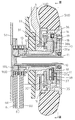
図1は、湾曲部2を上下方向に屈曲させるために操作部4に回転自在に配置された湾曲操作機構を示している。上下方向用湾曲操作ノブ5UDは、操作輪の内側部分が大きな空間になっており、湾曲操作機構全体の支軸10が、操作部4内のメインフレーム50に固定的に立設されて上下方向用湾曲操作ノブ5UDの中心軸線位置に配置されている。
FIG. 1 shows a bending operation mechanism that is rotatably arranged on the operation unit 4 in order to bend the
9UDは、上方向用操作ワイヤ6Uと下方向用操作ワイヤ6Dとが各々外周溝に半周ないし一周程度巻き付けられて引き出された上下方向用駆動プーリ、9RLは左右方向用駆動プーリである。
Reference numeral 9UD denotes an up-down direction drive pulley in which an upper
左右方向用駆動プーリ9RLに回転駆動力を伝達するように、支軸10を囲む筒状に形成されて一端が左右方向用駆動プーリ9RLに連結された左右方向用回転駆動筒11の他端側と、一端が上下方向用駆動プーリ9UDに連結された上下方向用回転駆動筒12の他端側とは各々操作部4の外部に突出している。
The other end side of the left-right direction
そして、上下方向用回転駆動筒12が軸線回りに回転自在に嵌合する上下方向用回転軸受13は、基部において支軸10の台座部分と固定され、各プーリ9UD,9RLの外周から操作ワイヤ6U,6D,6R,6Lが外れるのを規制するためのプーリカバーも兼ねている。
The vertical rotation bearing 13 into which the vertical
そして、上下方向用回転駆動筒12を軸線周りに回転させれば上下方向用駆動プーリ9UDが回転し、その回転方向に対応して上方向用操作ワイヤ6Uと下方向用操作ワイヤ6Dのどちらか一方が牽引操作される。同様に、左右方向用回転駆動筒11を軸線周りに回転させれば左右方向用駆動プーリ9RLが回転し、その回転方向に対応して右方向用操作ワイヤ6Rと左方向用操作ワイヤ6Lのどちらか一方が牽引操作される。
When the vertical
そして、上下方向用湾曲操作ノブ5UDと一体に形成された金属製の円盤状の座板16が、上下方向用湾曲操作ノブ5UDの内側空間部の外面側端部を塞ぐ状態に配置されていて、上下方向用回転駆動筒12と一体に形成された金属製の凹溝付回転板17の外端面が座板16の内面に対して軸線回りに回転自在に摺接している。
A metal disc-
図1におけるIII−III断面を図示する図3に示されるように、外周が全体として円形に形成された凹溝付回転板17の外周面の一部には凹溝21が形成されている。そして、基端が固定ネジ19で座板16に固定されたバネ性を有する部材からなるバネ性係合アーム18が、凹溝付回転板17の外周に沿って円弧状に配置されて、自由端であるバネ性係合アーム18の先端部分に凹溝21と係脱自在に噛み合う係合爪22が突出形成されている。
As shown in FIG. 3 illustrating a section taken along the line III-III in FIG. 1, a
バネ性係合アーム18は、外力が作用していない状態では係合爪22が凹溝21と噛み合う状態にセットされていて、そのようなバネ性係合アーム18は座板16と一体的に軸線周りに回動自在であり、上下方向用湾曲操作ノブ5UDに加えられる回転トルクが所定トルク以下の時は係合爪22が凹溝21に噛み合った状態を維持する。
The
したがって、上下方向用湾曲操作ノブ5UDが回転操作されるとバネ性係合アーム18が座板16と共に回動してそれにより凹溝付回転板17が回転させられ、上下方向用湾曲操作ノブ5UDに加えられた回転操作力が上下方向用回転駆動筒12等を経由して操作ワイヤ6U,6D側に伝達される。
Therefore, when the up / down direction bending operation knob 5UD is rotated, the
そして、上下方向用湾曲操作ノブ5UDに回転トルクが所定トルクを超えるような無理な操作力が加えられた時は、凹溝21に対する係合爪22の噛み合いが外れる状態にバネ性係合アーム18が弾性変形することにより、凹溝付回転板17が座板16に追従して回転しなくなり、上下方向用回転駆動筒12が上下方向用湾曲操作ノブ5UDにより回転駆動されなくなる。
When an unreasonable operating force is applied to the vertical bending operation knob 5UD so that the rotational torque exceeds a predetermined torque, the
このようにして、上下方向用湾曲操作ノブ5UDに一定以上の操作トルクが加えられた場合の安全確保のためのトルクリミット機構が、凹溝付回転板17、バネ性係合アーム18、凹溝21及び係合爪22等により構成されて上下方向用湾曲操作ノブ5UD内の空間に配置されている。
In this way, the torque limit mechanism for ensuring safety when an operation torque of a certain level or more is applied to the upward / downward bending operation knob 5UD includes the
図1に示される30〜38は、上下方向用湾曲操作ノブ5UDとそれに連結された上下方向用回転駆動筒12及び上下方向用駆動プーリ9UD等からなる上下方向用の湾曲操作機構を任意の回転位置で静止させるために、湾曲操作機構の回転動作に摩擦抵抗を付与するための湾曲保持機構であり、上下方向用湾曲操作ノブ5UD内の空間に収納配置されていて、上下方向用湾曲保持操作ノブ7UDにより摩擦力の付与と解除の操作を行うことができる。
30 to 38 shown in FIG. 1 arbitrarily rotate an up / down direction bending operation mechanism including an up / down direction bending operation knob 5UD, an up / down direction
図1におけるIV−IV断面を図示する図4にも示されるように、メインフレーム50に対して固定された状態になっている上下方向用回転軸受13の上端部付近に、不動台座30が固定ネジ31により固定されている。
As shown in FIG. 4 illustrating the IV-IV cross section in FIG. 1, the
上下方向用湾曲保持操作ノブ7UDは上下方向用回転軸受13の外面に軸線周りに回転自在に嵌着されていて、その上下方向用湾曲保持操作ノブ7UDと角穴/角軸係合して一体に回転する雄ネジ環32の外周に雄ネジが形成されている。
The up / down direction curve holding operation knob 7UD is fitted to the outer surface of the up / down direction rotary bearing 13 so as to be rotatable around the axis, and is engaged with the up / down direction curve holding operation knob 7UD by square holes / square shafts. A male screw is formed on the outer periphery of the
上下方向用湾曲保持操作ノブ7UDと雄ネジ環32の回転動作範囲は、雄ネジ環32に形成された円弧状溝33と、その円弧状溝33内に沿うように不動台座30から突設されたストッパピン34により一定に規制されている。
The rotation operation range of the up / down bending holding knob 7UD and the
雄ネジ環32の外周の雄ネジと螺合する雌ネジが、雌ネジ環35の下半側(図1において左側)の内周部に形成されている。Nが螺合部である。そして、雌ネジ環35の上半側の内周側に、金属円盤37が固定ネジ36で一体的に連結固定されている。
A female screw that engages with a male screw on the outer periphery of the
金属円盤37は例えば黄銅又はステンレス鋼等により形成されていて、図4に示されるように、金属円盤37の内周面は固定部材である不動台座30の外周面に対して、軸線周りには回転しないが軸線方向には移動自在に角穴/角軸係合している。したがって、金属円盤37と一体に動作する雌ネジ環35も、軸線周りには回転することができないが軸線方向には移動自在である。
The
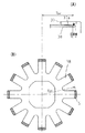
図1に示される38は、図5に単体の平面図が示され、図6に斜視図が示されるように、環状部38aの周囲にそれと一体に複数の放射状突出爪38bが形成された例えばバネ用ステンレス鋼板材等のようなバネ性のある金属板材からなる放射状板バネであり、全体として平面状に形成されて、環状部38aの内側部分は角穴になっている。
1 is a plan view of a single unit shown in FIG. 5, and a perspective view is shown in FIG. 6. As shown in FIG. 6, a plurality of radially projecting
放射状板バネ38の角穴部分は、図1に示されるように上下方向用回転駆動筒12の上端部近傍に係合していて、上下方向用回転駆動筒12と一体に軸線周りに回転するように組み付けられて、環状部38aの裏面側(図1において左方の面)が不動台座30の上端面に当接して保持されている。
As shown in FIG. 1, the square hole portion of the
そして、放射状板バネ38の放射状突出爪38bに対向する位置にある金属円盤37の面が、放射状突出爪38bの板面に対して斜め向きに圧接される圧接面37aになっている。より具体的には、金属円盤37の圧接面37aは内周側より外周側が放射状突出爪38bに接近した傘状の斜面(円錐面)に形成されている。
And the surface of the
このような構成により、上下方向用湾曲保持操作ノブ7UDが回転操作されると、それと一体に雄ネジ環32が軸線周りに回転し、螺合部Nで雄ネジ環32と螺合する雌ネジ環35及びそれと一体の金属円盤37が、軸線周りに回転することなく軸線方向に移動し、放射状板バネ38と金属円盤37の圧接面37aとの間の間隔が変化する。
With such a configuration, when the up / down bending holding operation knob 7UD is rotated, the
そして、上下方向用湾曲保持操作ノブ7UDが操作範囲の一端側(フリー側)にあるときは、図1に示されるように、放射状板バネ38と金属円盤37の圧接面37aとの間に僅かに隙間が形成されていて、放射状板バネ38と金属円盤37とが摺接せず、したがって、上下方向の操作ワイヤ6U,6Dを牽引操作するための湾曲操作機構(上下方向用湾曲操作ノブ5UD、上下方向用回転駆動筒12、上下方向用駆動プーリ9UD等)の回転動作に対して金属円盤37と放射状板バネ38による摩擦抵抗が加わらない。
When the up / down bending holding operation knob 7UD is on one end side (free side) of the operation range, as shown in FIG. 1, a slight gap is provided between the
上下方向用湾曲保持操作ノブ7UDが回転操作されて、操作範囲の他端側(ロック側)に移動すると、図7に示されるように、金属円盤37が矢印Aで示されるように移動することにより、金属円盤37の圧接面37aが放射状板バネ38に押し付けられて放射状板バネ38と金属円盤37とが摺接し、そこで発生する摩擦抵抗が、上下方向の操作ワイヤ6U,6Dを牽引操作するための湾曲操作機構の回転動作に対して作用する。
When the up / down direction bending holding operation knob 7UD is rotated and moved to the other end side (lock side) of the operation range, the
そのような上下方向用湾曲保持操作ノブ7UDの操作に際し、図1に示されるフリー状態から上下方向用湾曲保持操作ノブ7UDが僅かに回転操作されると、まず金属円盤37の圧接面37aが放射状板バネ38の放射状突出爪38bの最外周部分に接触して僅かに摩擦抵抗が発生し、さらに上下方向用湾曲保持操作ノブ7UDをロック側に回転させていくと、圧接面37aに圧接される範囲が次第に放射状突出爪38bの内側寄りの部分を含む状態になって圧接量が増大し、発生する摩擦抵抗が大きくなる。
When such an up / down bending holding operation knob 7UD is operated, when the up / down bending holding operation knob 7UD is slightly rotated from the free state shown in FIG. 1, first, the
そして、上下方向用湾曲保持操作ノブ7UDを図1に示されるフリー側に戻せば、放射状板バネ38が元の平面状態に戻って金属円盤37に圧接されない状態に戻る。このようにして放射状板バネ38の放射状突出爪38bと金属円盤37の圧接面37aとが圧接する状態と分離する状態とを任意に切り換え操作することができ、その間において、放射状板バネ38の放射状突出爪38bと金属円盤37との圧接量を連続的に可変することができる。
When the up / down bending holding knob 7UD is returned to the free side shown in FIG. 1, the
そのようにして摩擦抵抗の大きさが変化する過程においては、斜面(円錐面)状に形成されている金属円盤37の圧接面37aに圧接される放射状板バネ38の圧接部分が斜面に沿う状態に弾性変形する。
In such a process in which the magnitude of the frictional resistance is changed, the pressure contact portion of the
図8(A),(B)、及び図9(A),(B)は、そのような金属円盤37の圧接面37aと放射状板バネ38との圧接状態の変化の過程を示す側面半断面図と放射状板バネ38の平面図であり、圧接面積Sが大きくなるのに伴って、圧接部の平均回転半径RAVが小さくなる(平面どうしが全面で圧接する機構では、圧接部の平均回転半径RAVは変化しない)。
FIGS. 8A and 8B and FIGS. 9A and 9B are side half cross-sections showing the process of changing the pressure contact state between the
すると、圧接部の摩擦係数をμ、圧接面に対し垂直に加わる力をFとすると、上下方向用湾曲保持操作ノブ7UDに作用するブレーキトルク=μ・F・RAVなので、圧接部の平均回転半径RAVが次第に小さくなる本実施例の機構では、圧接部の平均回転半径RAVが変化しない機構に比べてブレーキトルクの変化が緩やかで、組み立て時の調整作業を正確且つ容易に行うことができ、また、ブレーキトルクの経時変化が小さくて優れた耐久性が得られる。 Then, if the friction coefficient of the pressure contact portion is μ and the force applied perpendicularly to the pressure contact surface is F, the brake torque acting on the up and down direction curve holding operation knob 7UD = μ · F · R AV, so the average rotation of the pressure contact portion In the mechanism of the present embodiment in which the radius R AV gradually decreases, the brake torque changes more slowly than the mechanism in which the average rotation radius R AV of the press contact portion does not change, and adjustment work during assembly can be performed accurately and easily. In addition, excellent durability can be obtained because the change in brake torque with time is small.
このように、上下方向の湾曲操作機構(上下方向用湾曲操作ノブ5UD、上下方向用回転駆動筒12、上下方向用駆動プーリ9UD等)の回転動作に摩擦抵抗を付与するために相対的に回転動作をする摩擦抵抗発生部材が金属円盤37と放射状板バネ38のみで構成されていて、それらは金属により薄く形成することができる。
In this manner, the bending operation mechanism in the vertical direction (vertical bending operation knob 5UD, vertical
その結果、上下方向用の湾曲保持機構30〜38を薄型に構成して湾曲操作機構の上下方向用湾曲操作ノブ5UD内の空間に収納配置することができ、その結果、上下方向用湾曲操作ノブ5UDを小型化して操作性を向上させたり、上下方向用湾曲操作ノブ5UDを大型にすることなくトルクリミット機構(凹溝付回転板17、バネ性係合アーム18、凹溝21、係合爪22)等を上下方向用湾曲操作ノブ5UD内の空間に組み込むことができる。また、摩擦抵抗発生部材37,38が熱や経時的な条件等で劣化し難く、優れた耐久性を得ることができる。
As a result, the
また、金属どうしの接触部においては動摩擦力に比べて静止摩擦力が確実に大きいので、金属製の放射状板バネ38と金属円盤37との圧接により、上下方向用湾曲保持操作ノブ7UDを操作ワイヤ6U,6D側から受ける牽引反力に負けずにピタッと確実な静止状態に固定することができる。
Further, since the static frictional force is surely larger than the dynamic frictional force at the contact portion between the metals, the bending holding operation knob 7UD for the vertical direction is operated by the pressure contact between the metal
そして、その状態から上下方向用湾曲保持操作ノブ7UDを回転操作すると、上下方向用湾曲保持操作ノブ7UDが一旦動きだした後は小さな摩擦抵抗で軽く動いて操作性がよく、次の静止位置において、上下方向用湾曲保持操作ノブ7UDが再び操作ワイヤ6U,6D側から受ける牽引反力に負けずにピタッと確実に固定される。
Then, if the up / down direction bending holding operation knob 7UD is rotated from that state, after the up / down direction bending holding operation knob 7UD starts to move once, it moves lightly with a small frictional resistance, and the operability is good. The bending holding operation knob 7UD for the up and down direction is securely fixed without losing the pulling reaction force received from the
なお、放射状板バネ38に形成された放射状突出爪38bの少なくとも金属円盤37が圧接される稜線部分は全てアール面取りされて、金属円盤37との摺接が滑らかに行われるようになっており、金属円盤37が必ず放射状板バネ38の最外周側から摺接するので、発生する摩擦抵抗の大きさにバラツキが発生せず適正な摩擦抵抗が安定的に付与される。
In addition, at least the ridge line portion where the
また、本発明は上記実施例に限定されるものではなく、例えば図10〜図12に例示されるように、放射状板バネ38の放射状突出爪38bの数や形状等は多様な態様をとることができる。
In addition, the present invention is not limited to the above-described embodiment, and the number and shape of the
また、放射状板バネ38を全体として傘状(円錐状)に形成して、金属円盤37の圧接面37aを平面状に形成してもよく、放射状板バネ38を非回転部に配置して金属円盤37を回転部(上下方向用回転駆動筒12)側に取り付けてもよい。また、本発明の湾曲保持機構を左右方向用湾曲操作ノブ5RLに組み込んでもよい。
Alternatively, the
1 挿入部
2 湾曲部
4 操作部
5UD 上下方向用湾曲操作ノブ(湾曲操作機構)
6U 上方向用操作ワイヤ
6D 下方向用操作ワイヤ
7UD 上下方向用湾曲保持操作ノブ(湾曲保持操作手段)
9UD 上下方向用駆動プーリ(湾曲操作機構)
12 上下方向用回転駆動筒(湾曲操作機構)
30〜38 湾曲保持機構
30 不動台座
32 雄ネジ環
35 雌ネジ環
37 金属円盤(摩擦抵抗発生部材)
37a 圧接面
38 放射状板バネ(摩擦抵抗発生部材)
38a 環状部
38b 放射状突出爪
DESCRIPTION OF
6U
9UD Drive pulley for vertical direction (bending operation mechanism)
12 Vertically rotating drive cylinder (bending operation mechanism)
30 to 38
37a
Claims (9)
上記湾曲操作機構の回転動作に摩擦抵抗を付与するために相対的に回転動作をする摩擦抵抗発生部材が、環状部の周囲にそれと一体に複数の放射状突出爪が形成されたバネ性のある金属板材からなる放射状板バネと、上記放射状板バネの板面に対して斜め向きに圧接される圧接面を有する金属円盤とで構成されていることを特徴とする内視鏡の湾曲保持機構。 Friction resistance can be imparted to the rotational operation of the bending operation mechanism so that the bending operation mechanism that is rotatably arranged on the operation unit in order to bend the bending unit by remote operation is stopped at an arbitrary rotation position. In the endoscope bending maintenance mechanism,
A frictional resistance generating member that relatively rotates to give a frictional resistance to the rotational operation of the bending operation mechanism is a metal having a spring property in which a plurality of radially protruding claws are integrally formed around the annular portion A bending holding mechanism for an endoscope, comprising: a radial leaf spring made of a plate material; and a metal disc having a pressure contact surface pressed obliquely with respect to the plate surface of the radial leaf spring.
Priority Applications (3)
| Application Number | Priority Date | Filing Date | Title |
|---|---|---|---|
| JP2007028708A JP4928969B2 (en) | 2006-04-26 | 2007-02-08 | Endoscope bending retention mechanism |
| US11/737,305 US7828725B2 (en) | 2006-04-26 | 2007-04-19 | Bent state holding mechanism of an endoscope |
| DE102007019781.2A DE102007019781B4 (en) | 2006-04-26 | 2007-04-26 | Bending state holding mechanism of an endoscope |
Applications Claiming Priority (3)
| Application Number | Priority Date | Filing Date | Title |
|---|---|---|---|
| JP2006121597 | 2006-04-26 | ||
| JP2006121597 | 2006-04-26 | ||
| JP2007028708A JP4928969B2 (en) | 2006-04-26 | 2007-02-08 | Endoscope bending retention mechanism |
Publications (3)
| Publication Number | Publication Date |
|---|---|
| JP2007313292A JP2007313292A (en) | 2007-12-06 |
| JP2007313292A5 JP2007313292A5 (en) | 2009-04-02 |
| JP4928969B2 true JP4928969B2 (en) | 2012-05-09 |
Family
ID=38622441
Family Applications (1)
| Application Number | Title | Priority Date | Filing Date |
|---|---|---|---|
| JP2007028708A Active JP4928969B2 (en) | 2006-04-26 | 2007-02-08 | Endoscope bending retention mechanism |
Country Status (3)
| Country | Link |
|---|---|
| US (1) | US7828725B2 (en) |
| JP (1) | JP4928969B2 (en) |
| DE (1) | DE102007019781B4 (en) |
Families Citing this family (60)
| Publication number | Priority date | Publication date | Assignee | Title |
|---|---|---|---|---|
| JP5297003B2 (en) * | 2007-06-06 | 2013-09-25 | 富士フイルム株式会社 | Endoscope |
| JP5159181B2 (en) | 2007-06-21 | 2013-03-06 | Hoya株式会社 | Structure of connecting part in endoscope |
| JP5137477B2 (en) | 2007-06-22 | 2013-02-06 | Hoya株式会社 | Structure of connecting part in endoscope |
| JP5006708B2 (en) | 2007-06-22 | 2012-08-22 | Hoya株式会社 | End structure of endoscope rotation mechanism |
| JP5186223B2 (en) * | 2008-01-25 | 2013-04-17 | Hoya株式会社 | Endoscope bending operation device |
| US8790250B2 (en) | 2008-12-10 | 2014-07-29 | Ambu A/S | Endoscope bending section control mechanism |
| JP5331507B2 (en) * | 2009-02-18 | 2013-10-30 | 富士フイルム株式会社 | Endoscope |
| US9474440B2 (en) | 2009-06-18 | 2016-10-25 | Endochoice, Inc. | Endoscope tip position visual indicator and heat management system |
| US10524645B2 (en) | 2009-06-18 | 2020-01-07 | Endochoice, Inc. | Method and system for eliminating image motion blur in a multiple viewing elements endoscope |
| US10130246B2 (en) | 2009-06-18 | 2018-11-20 | Endochoice, Inc. | Systems and methods for regulating temperature and illumination intensity at the distal tip of an endoscope |
| JP5430299B2 (en) * | 2009-09-03 | 2014-02-26 | Hoya株式会社 | Rotation position holding mechanism of rotation operation unit |
| JP5393383B2 (en) * | 2009-09-30 | 2014-01-22 | Hoya株式会社 | Endoscope treatment tool raising operation device |
| US8974372B2 (en) | 2010-08-25 | 2015-03-10 | Barry M. Fell | Path-following robot |
| US9402682B2 (en) | 2010-09-24 | 2016-08-02 | Ethicon Endo-Surgery, Llc | Articulation joint features for articulating surgical device |
| US9545253B2 (en) | 2010-09-24 | 2017-01-17 | Ethicon Endo-Surgery, Llc | Surgical instrument with contained dual helix actuator assembly |
| US9877720B2 (en) | 2010-09-24 | 2018-01-30 | Ethicon Llc | Control features for articulating surgical device |
| US9089327B2 (en) | 2010-09-24 | 2015-07-28 | Ethicon Endo-Surgery, Inc. | Surgical instrument with multi-phase trigger bias |
| US9706908B2 (en) | 2010-10-28 | 2017-07-18 | Endochoice, Inc. | Image capture and video processing systems and methods for multiple viewing element endoscopes |
| US10663714B2 (en) | 2010-10-28 | 2020-05-26 | Endochoice, Inc. | Optical system for an endoscope |
| KR20120055916A (en) * | 2010-11-24 | 2012-06-01 | 삼성전자주식회사 | Endoscope |
| US10517464B2 (en) | 2011-02-07 | 2019-12-31 | Endochoice, Inc. | Multi-element cover for a multi-camera endoscope |
| DE102013101202A1 (en) * | 2013-02-07 | 2014-08-07 | Karl Storz Gmbh & Co. Kg | Endoscopic instrument |
| US10058310B2 (en) | 2013-03-13 | 2018-08-28 | Ethicon Llc | Electrosurgical device with drum-driven articulation |
| US9636003B2 (en) | 2013-06-28 | 2017-05-02 | Endochoice, Inc. | Multi-jet distributor for an endoscope |
| US10595714B2 (en) | 2013-03-28 | 2020-03-24 | Endochoice, Inc. | Multi-jet controller for an endoscope |
| CN105358043B (en) | 2013-05-07 | 2018-12-21 | 恩多巧爱思股份有限公司 | The white balance shell being used together with more observation element endoscopes |
| WO2014186519A2 (en) * | 2013-05-17 | 2014-11-20 | Endochoice, Inc. | Endoscope control unit with braking system |
| US9949623B2 (en) | 2013-05-17 | 2018-04-24 | Endochoice, Inc. | Endoscope control unit with braking system |
| JP5604561B2 (en) * | 2013-05-21 | 2014-10-08 | 哲丸 宮脇 | Endoscope |
| US10064541B2 (en) | 2013-08-12 | 2018-09-04 | Endochoice, Inc. | Endoscope connector cover detection and warning system |
| US9943218B2 (en) | 2013-10-01 | 2018-04-17 | Endochoice, Inc. | Endoscope having a supply cable attached thereto |
| US9968242B2 (en) | 2013-12-18 | 2018-05-15 | Endochoice, Inc. | Suction control unit for an endoscope having two working channels |
| WO2015112747A2 (en) | 2014-01-22 | 2015-07-30 | Endochoice, Inc. | Image capture and video processing systems and methods for multiple viewing element endoscopes |
| US11234581B2 (en) | 2014-05-02 | 2022-02-01 | Endochoice, Inc. | Elevator for directing medical tool |
| EP3171752B1 (en) | 2014-07-21 | 2019-12-11 | EndoChoice, Inc. | Multi-focal, multi-camera endoscope systems |
| US10542877B2 (en) | 2014-08-29 | 2020-01-28 | Endochoice, Inc. | Systems and methods for varying stiffness of an endoscopic insertion tube |
| EP3219246A4 (en) * | 2014-11-12 | 2018-09-05 | Olympus Corporation | Dialing unit and introduction device |
| US10123684B2 (en) | 2014-12-18 | 2018-11-13 | Endochoice, Inc. | System and method for processing video images generated by a multiple viewing elements endoscope |
| EP3242584B1 (en) | 2015-01-05 | 2020-07-22 | EndoChoice, Inc. | Tubed manifold of a multiple viewing elements endoscope |
| US10376181B2 (en) | 2015-02-17 | 2019-08-13 | Endochoice, Inc. | System for detecting the location of an endoscopic device during a medical procedure |
| US10078207B2 (en) | 2015-03-18 | 2018-09-18 | Endochoice, Inc. | Systems and methods for image magnification using relative movement between an image sensor and a lens assembly |
| US10401611B2 (en) | 2015-04-27 | 2019-09-03 | Endochoice, Inc. | Endoscope with integrated measurement of distance to objects of interest |
| WO2016187124A1 (en) | 2015-05-17 | 2016-11-24 | Endochoice, Inc. | Endoscopic image enhancement using contrast limited adaptive histogram equalization (clahe) implemented in a processor |
| SG10202101464RA (en) | 2015-09-17 | 2021-04-29 | Endomaster Pte Ltd | Improved flexible robotic endoscopy system |
| US20170119474A1 (en) | 2015-10-28 | 2017-05-04 | Endochoice, Inc. | Device and Method for Tracking the Position of an Endoscope within a Patient's Body |
| AU2016361331B2 (en) | 2015-11-24 | 2021-10-28 | Endochoice, Inc. | Disposable air/water and suction valves for an endoscope |
| EP3419497B1 (en) | 2016-02-24 | 2022-06-01 | Endochoice, Inc. | Circuit board assembly for a multiple viewing element endoscope using cmos sensors |
| WO2017160792A1 (en) | 2016-03-14 | 2017-09-21 | Endochoice, Inc. | System and method for guiding and tracking a region of interest using an endoscope |
| WO2017222716A1 (en) | 2016-06-21 | 2017-12-28 | Endochoice, Inc. | Endoscope system with multiple connection interfaces to interface with different video data signal sources |
| DE102016121056A1 (en) * | 2016-11-04 | 2018-05-09 | Digital Endoscopy Gmbh | WORK CHANNEL ELEMENT, ENDOSCOPE WITH A WORK CHANNEL ELEMENT, AND METHOD FOR USING A WORK CHANNEL IN AN ENDOSCOPE |
| JP3215550U (en) * | 2017-01-25 | 2018-03-29 | 珠海嘉潤医用影像科技有限公司Zhuhai Kaden Medical Imaging Technology Co., Ltd | Control mechanism for tension cord of bronchoscope |
| EP3513706A1 (en) | 2018-01-19 | 2019-07-24 | Ambu A/S | A method for fixation of a wire portion of an endoscope, and an endoscope |
| EP3517017B1 (en) | 2018-01-26 | 2023-01-18 | Ambu A/S | A method for fixation of a wire portion of an endoscope, and an endoscope |
| US11259688B2 (en) * | 2018-04-18 | 2022-03-01 | Duke University | Devices for assisting manipulation of input mechanisms of medical instruments |
| DE102018130553A1 (en) * | 2018-11-30 | 2020-06-04 | Henke-Sass, Wolf Gmbh | endoscope |
| DE102020111885A1 (en) * | 2020-04-30 | 2021-11-04 | Ambu A/S | Steering arrangement for an endoscope, in particular for a disposable endoscope |
| DE102020118043A1 (en) | 2020-07-08 | 2022-01-13 | Karl Storz Se & Co. Kg | Deflection control mechanism for a steerable flexible endoscope, steerable flexible endoscope and method of controlling a flexible endoscope |
| CA3205258A1 (en) * | 2021-01-26 | 2022-08-04 | Versitech Limited | A steerable arm for use in endoscopic surgical procedures |
| WO2023285520A1 (en) | 2021-07-14 | 2023-01-19 | Karl Storz Se & Co. Kg | Deflection control mechanism for a steerable flexible endoscope, steerable flexible endoscope, and method for controlling a flexible endoscope |
| WO2023191068A1 (en) * | 2022-03-31 | 2023-10-05 | 日本ゼオン株式会社 | Medical device |
Family Cites Families (11)
| Publication number | Priority date | Publication date | Assignee | Title |
|---|---|---|---|---|
| JPS58157433A (en) * | 1982-03-15 | 1983-09-19 | オリンパス光学工業株式会社 | Ultrasonic diagnostic apparatus of body cavity |
| US5329887A (en) * | 1992-04-03 | 1994-07-19 | Vision Sciences, Incorporated | Endoscope control assembly with removable control knob/brake assembly |
| US5507717A (en) * | 1993-05-24 | 1996-04-16 | Olympus Optical Co., Ltd. | Device for bending the insertion section of an endoscope |
| JP3368649B2 (en) * | 1993-12-28 | 2003-01-20 | オリンパス光学工業株式会社 | Endoscope bending operation device |
| US5496260A (en) * | 1994-05-16 | 1996-03-05 | Welch Allyn, Inc. | Torque override knob for endoscopes, borescopes, or guide tubes |
| JP3866786B2 (en) * | 1995-10-06 | 2007-01-10 | オリンパス株式会社 | Endoscope |
| JP3762515B2 (en) | 1997-04-14 | 2006-04-05 | オリンパス株式会社 | Endoscope bending operation device |
| JP4362664B2 (en) * | 1999-02-10 | 2009-11-11 | フジノン株式会社 | Endoscope angle control device |
| US6673012B2 (en) * | 2000-04-19 | 2004-01-06 | Pentax Corporation | Control device for an endoscope |
| JP4323300B2 (en) | 2003-12-03 | 2009-09-02 | オリンパス株式会社 | Endoscope |
| US20060252993A1 (en) | 2005-03-23 | 2006-11-09 | Freed David I | Medical devices and systems |
-
2007
- 2007-02-08 JP JP2007028708A patent/JP4928969B2/en active Active
- 2007-04-19 US US11/737,305 patent/US7828725B2/en active Active
- 2007-04-26 DE DE102007019781.2A patent/DE102007019781B4/en active Active
Also Published As
| Publication number | Publication date |
|---|---|
| DE102007019781A1 (en) | 2007-11-29 |
| DE102007019781B4 (en) | 2022-02-24 |
| JP2007313292A (en) | 2007-12-06 |
| US20070255104A1 (en) | 2007-11-01 |
| US7828725B2 (en) | 2010-11-09 |
Similar Documents
| Publication | Publication Date | Title |
|---|---|---|
| JP4928969B2 (en) | Endoscope bending retention mechanism | |
| JP4827598B2 (en) | Endoscope bending retention mechanism | |
| JP4847783B2 (en) | Endoscope bending operation device | |
| US9089263B2 (en) | Endoscope and instrument lifting operation device for the same | |
| JP2007313292A5 (en) | ||
| JP2004204983A (en) | Hinge device | |
| WO2015119000A1 (en) | Steering apparatus | |
| JP2018528833A (en) | Brake system | |
| JPWO2020021934A1 (en) | Sealing device | |
| JP5717933B2 (en) | Hinge mechanism and panel device | |
| JP2011112072A (en) | Power transmission device | |
| JP4464986B2 (en) | HINGE DEVICE AND ELECTRONIC DEVICE USING HINGE DEVICE | |
| JP2017181598A (en) | Hinge and office machine having the same | |
| JP2012211629A (en) | Tilt hinge, and electronic apparatus with the same | |
| JP5507008B2 (en) | Hinge mechanism and in-vehicle display device | |
| JP2000229061A (en) | Angling instrument of endocope | |
| JP2010203129A (en) | Opening/closing device for automatic door and torque limiter | |
| JP4643721B2 (en) | Endoscope angle control device | |
| JP6918426B2 (en) | Torque transmitter | |
| JP2008083557A (en) | Lens barrel | |
| JP5385827B2 (en) | Scanning drive device | |
| JP4163090B2 (en) | Fastener for mounting a spindle of a vehicle sun visor | |
| KR101092196B1 (en) | Disk for butterfly valve | |
| JP4737626B2 (en) | Rotating body mechanism | |
| JPH1068412A (en) | Shaft lock device |
Legal Events
| Date | Code | Title | Description |
|---|---|---|---|
| A711 | Notification of change in applicant |
Free format text: JAPANESE INTERMEDIATE CODE: A712 Effective date: 20080502 |
|
| A521 | Request for written amendment filed |
Free format text: JAPANESE INTERMEDIATE CODE: A523 Effective date: 20090217 |
|
| A621 | Written request for application examination |
Free format text: JAPANESE INTERMEDIATE CODE: A621 Effective date: 20091125 |
|
| A977 | Report on retrieval |
Free format text: JAPANESE INTERMEDIATE CODE: A971007 Effective date: 20120119 |
|
| TRDD | Decision of grant or rejection written | ||
| A01 | Written decision to grant a patent or to grant a registration (utility model) |
Free format text: JAPANESE INTERMEDIATE CODE: A01 Effective date: 20120125 |
|
| A01 | Written decision to grant a patent or to grant a registration (utility model) |
Free format text: JAPANESE INTERMEDIATE CODE: A01 |
|
| A61 | First payment of annual fees (during grant procedure) |
Free format text: JAPANESE INTERMEDIATE CODE: A61 Effective date: 20120213 |
|
| FPAY | Renewal fee payment (event date is renewal date of database) |
Free format text: PAYMENT UNTIL: 20150217 Year of fee payment: 3 |
|
| R150 | Certificate of patent or registration of utility model |
Ref document number: 4928969 Country of ref document: JP Free format text: JAPANESE INTERMEDIATE CODE: R150 Free format text: JAPANESE INTERMEDIATE CODE: R150 |
|
| S531 | Written request for registration of change of domicile |
Free format text: JAPANESE INTERMEDIATE CODE: R313531 |
|
| R350 | Written notification of registration of transfer |
Free format text: JAPANESE INTERMEDIATE CODE: R350 |
|
| R250 | Receipt of annual fees |
Free format text: JAPANESE INTERMEDIATE CODE: R250 |
|
| R250 | Receipt of annual fees |
Free format text: JAPANESE INTERMEDIATE CODE: R250 |
|
| R250 | Receipt of annual fees |
Free format text: JAPANESE INTERMEDIATE CODE: R250 |
|
| R250 | Receipt of annual fees |
Free format text: JAPANESE INTERMEDIATE CODE: R250 |
|
| R250 | Receipt of annual fees |
Free format text: JAPANESE INTERMEDIATE CODE: R250 |
|
| R250 | Receipt of annual fees |
Free format text: JAPANESE INTERMEDIATE CODE: R250 |
|
| R250 | Receipt of annual fees |
Free format text: JAPANESE INTERMEDIATE CODE: R250 |
|
| R250 | Receipt of annual fees |
Free format text: JAPANESE INTERMEDIATE CODE: R250 |