JP4928303B2 - COMMUNICATION DEVICE, ITS CONTROL METHOD, PROGRAM - Google Patents
COMMUNICATION DEVICE, ITS CONTROL METHOD, PROGRAM Download PDFInfo
- Publication number
- JP4928303B2 JP4928303B2 JP2007040905A JP2007040905A JP4928303B2 JP 4928303 B2 JP4928303 B2 JP 4928303B2 JP 2007040905 A JP2007040905 A JP 2007040905A JP 2007040905 A JP2007040905 A JP 2007040905A JP 4928303 B2 JP4928303 B2 JP 4928303B2
- Authority
- JP
- Japan
- Prior art keywords
- address
- state
- time
- communication
- receiving
- Prior art date
- Legal status (The legal status is an assumption and is not a legal conclusion. Google has not performed a legal analysis and makes no representation as to the accuracy of the status listed.)
- Expired - Fee Related
Links
Images


Classifications
-
- H—ELECTRICITY
- H04—ELECTRIC COMMUNICATION TECHNIQUE
- H04L—TRANSMISSION OF DIGITAL INFORMATION, e.g. TELEGRAPHIC COMMUNICATION
- H04L61/00—Network arrangements, protocols or services for addressing or naming
- H04L61/50—Address allocation
- H04L61/5053—Lease time; Renewal aspects
-
- H—ELECTRICITY
- H04—ELECTRIC COMMUNICATION TECHNIQUE
- H04L—TRANSMISSION OF DIGITAL INFORMATION, e.g. TELEGRAPHIC COMMUNICATION
- H04L67/00—Network arrangements or protocols for supporting network services or applications
- H04L67/14—Session management
-
- H—ELECTRICITY
- H04—ELECTRIC COMMUNICATION TECHNIQUE
- H04L—TRANSMISSION OF DIGITAL INFORMATION, e.g. TELEGRAPHIC COMMUNICATION
- H04L61/00—Network arrangements, protocols or services for addressing or naming
- H04L61/50—Address allocation
- H04L61/5007—Internet protocol [IP] addresses
- H04L61/5014—Internet protocol [IP] addresses using dynamic host configuration protocol [DHCP] or bootstrap protocol [BOOTP]
-
- H—ELECTRICITY
- H04—ELECTRIC COMMUNICATION TECHNIQUE
- H04L—TRANSMISSION OF DIGITAL INFORMATION, e.g. TELEGRAPHIC COMMUNICATION
- H04L67/00—Network arrangements or protocols for supporting network services or applications
- H04L67/01—Protocols
- H04L67/04—Protocols specially adapted for terminals or networks with limited capabilities; specially adapted for terminal portability
Landscapes
- Engineering & Computer Science (AREA)
- Computer Networks & Wireless Communication (AREA)
- Signal Processing (AREA)
- Small-Scale Networks (AREA)
- Facsimiles In General (AREA)
Abstract
Description
本発明は、ネットワークに接続可能な装置のアドレス管理に関する。 The present invention relates to address management of devices connectable to a network.
近年、ネットワークのブロードバンド化が普及しており、ADSL(Asymmetric Digital Subscriber Line)やFTTH(Fiber To The Home)に見られるようなコンシューマ向けのアクセス回線が普及してきた。また、屋外、家庭内でアクセスポイントやPHS(Personal Handyphone System)などを利用してネットワーク通信を行える無線インフラも整備されてきている。さらに、これらインフラを利用して遠隔地のパーソナルコンピュータ等に撮影した画像を送信することができるデジタルカメラも提案されている。 In recent years, network broadbandization has become widespread, and access lines for consumers such as those found in ADSL (Asymmetric Digital Subscriber Line) and FTTH (Fiber To The Home) have become widespread. In addition, a wireless infrastructure that can perform network communication using an access point, a PHS (Personal Handyphone System), or the like outdoors or at home has been developed. Furthermore, a digital camera that can transmit a photographed image to a remote personal computer using these infrastructures has also been proposed.
一方、IP(Internet Protocol)ネットワークで通信するためには、IPアドレスやコンフィグレーション情報などの情報を取得する必要がある。この取得の仕組みの1つとしてDHCP(Dynamic Host Configuration Protocol)機能が考え出されている。この機能は、DHCPクライアントとDHCPサーバとが連携して動作することにより実現される。予めDHCPサーバにはDHCPクライアントに割り振るためのIPアドレスのほか、IPネットワークで通信するためのデフォルトゲートウェイやDNSなどの各種サーバのIPアドレスを設定しておく。DHCPクライアントは、DHCPサーバからこれらの情報をシステムの起動時に取得することで、ネットワーク情報の設定を自動的に、ユーザの手を煩わすことなく行うことができる。 On the other hand, in order to communicate on an IP (Internet Protocol) network, it is necessary to acquire information such as an IP address and configuration information. As one of the acquisition mechanisms, a DHCP (Dynamic Host Configuration Protocol) function has been devised. This function is realized by the DHCP client and the DHCP server operating in cooperation. In addition to the IP address assigned to the DHCP client, the IP address of various servers such as a default gateway and DNS for communicating over the IP network is set in advance in the DHCP server. The DHCP client obtains these pieces of information from the DHCP server when the system is started, so that the network information can be automatically set without bothering the user.
さらに、携帯端末機器(例えば携帯電話、PHS、パーソナルコンピュータ、PDA、デジタルカメラなど)では、通信モードが終了したときに、IPネットワークに接続する機能を搭載するブロックに電力供給を停止することができる。このことにより、ネットワーク切断中は通信に関するブロックに通電をしないため、無駄な電力消費がなくなり、消費電力の省力化を実現できる。 Furthermore, in a mobile terminal device (for example, a mobile phone, PHS, personal computer, PDA, digital camera, etc.), when the communication mode ends, power supply can be stopped to a block equipped with a function for connecting to an IP network. . As a result, the communication-related block is not energized while the network is disconnected, so that unnecessary power consumption is eliminated and power saving can be realized.
これらの機器は、再び通信を開始しIPネットワ−クへ再接続する際には、再接続のたびにIPアドレスなどの取得処理が必要となる。そのため、DHCP機能によるネットワーク設定に必要な情報の取得処理に時間がかかるという問題があった。また、ネットワークに多くのDHCPクライアントを接続し、1つのDHCPサーバで管理する場合には、DHCPサーバへのトラフィックが増大するという問題があった。 When these devices start communication again and reconnect to the IP network, an IP address and the like must be acquired every time they are reconnected. For this reason, there is a problem that it takes time to obtain information necessary for network setting by the DHCP function. In addition, when many DHCP clients are connected to the network and managed by one DHCP server, there is a problem that traffic to the DHCP server increases.
このため、IPネットワークへの接続確立を最初の通信に関する設定時に行い、2回目以降の通信には、最初に設定した情報を用いて通信を行う技術が知られている(特許文献1参照)。この技術により、DHCPサーバへのトラフィックをある程度抑制することができる。
しかしながら、特許文献1に記載されたデジタルカメラは、DHCP機能を用いて2回目以降の通信の設定を行う際に、最初の通信の設定時に取得した設定情報が使用可能であるか否かを判断する。そのため、最初の通信に関する設定時に取得した設定情報で外部装置との通信を試みて、通信に失敗すれば設定情報を再取得しに行かなければならない。したがって、DHCP機能によるネットワーク設定に必要な情報の取得処理に時間がかかるという問題があった。
However, the digital camera described in
上述の課題を解決するために、本発明に係る通信装置は、外部機器と通信しデータを送受信することが可能な通信装置であって、前記外部機器との通信に用いるアドレス及び前記アドレスのリース期間を受信する受信手段と、前記受信手段によるアドレスの受信から経過した時間と前記アドレスのリース期間とから、前記リース期間の残り時間を算出する算出手段と、前記通信装置に供給する電力を制御することで、第1の状態と、前記第1の状態よりも供給する電力を少なくする第2の状態とを切り替える電力制御手段と、データの送信に要する時間を予測し、予測された時間に基づき閾値を設定する設定手段と、前記第2の状態から前記第1の状態に移行した際に、前記アドレスが有効か否か判断する判断手段とを有し、前記判断手段は、前記リース期間の残り時間が前記設定手段により設定された閾値よりも長い場合には前記アドレスが有効であると判断し、前記判断手段により前記アドレスが有効であると判断された場合は前記受信したアドレスを用いて通信を行い、前記アドレスが有効でないと判断された場合は前記受信手段により再度アドレスを受信することを特徴とする。 In order to solve the above-described problem, a communication device according to the present invention is a communication device capable of communicating with an external device and transmitting / receiving data, the address used for communication with the external device and the lease of the address A receiving means for receiving a period; a calculating means for calculating a remaining time of the lease period from a time elapsed since the reception of the address by the receiving means and a lease period of the address; and control of power supplied to the communication device By doing so, the power control means for switching between the first state and the second state in which less power is supplied than in the first state, the time required for data transmission is predicted, and the predicted time is reached. Setting means for setting a threshold based on the determination means, and a determination means for determining whether or not the address is valid when the second state is shifted to the first state. When the remaining time of the lease period is longer than the threshold set by the setting means, the address is determined to be valid, and when the determination means determines that the address is valid, the address is received. Communication is performed using an address, and when it is determined that the address is not valid, the address is received again by the receiving means .
本発明に係る通信装置によれば、外部機器との通信に必要なアドレスのリース期間を考慮してネットワークへの接続の有無を判断し、前記アドレスが有効でない場合にアドレスの再取得を行う。したがって、通信するたびにネットワークに接続する時間を短縮し、迅速にネットワークへ接続できる。 According to the communication apparatus of the present invention, the presence / absence of connection to the network is determined in consideration of the lease period of the address necessary for communication with the external device, and the address is reacquired when the address is not valid. Accordingly, it is possible to shorten the time for connecting to the network every time communication is performed, and to quickly connect to the network.
<第1の実施形態>
実施例1として、以下の図面を参照して本発明のネットワーク機器に係る最良な実施形態について説明する。なお、本実施形態では、被写体を撮像して画像データの出力が可能なカメラ、デジタルカメラ、デジタルビデオカメラなどの撮像装置に適用することができる。
<First Embodiment>
As a first embodiment, the best embodiment according to the network device of the present invention will be described with reference to the following drawings. Note that the present embodiment can be applied to an imaging apparatus such as a camera, a digital camera, or a digital video camera that can capture an image of a subject and output image data.
図1は、本実施形態に係る撮像システムの全体構成を示す構成図である。100、100a、100bは撮像装置である。200、200aはアクセスポイントである。300、300a、300bはルーターである。400はネットワークである。500,500aはパーソナルコンピュータである。600、600aはサーバ装置である。
FIG. 1 is a configuration diagram showing the overall configuration of the imaging system according to the present embodiment.
撮像装置100が無線LAN(Local Area Network)機能を使用する場合には、アクセスポイント200及びルーター300を介してネットワーク400へ接続する。また、有線でのLAN機能を使用する場合には、ルーター300aに直接LANケーブルなどを介して接続し、ネットワーク400へ接続される。
When the
パーソナルコンピュータ500、500a、サーバ装置600、600aは、それぞれルーター300、300a、300bを介しネットワーク400に接続される。
The
本実施形態では、サーバ装置600、600aがDHCPサーバの機能を搭載している。これは、DHCPクライアントとの最初の通信設定時に動的にIPアドレスを割り当て、通信終了時にIPアドレスを回収するための機能である。
In the present embodiment, the
また、撮像装置100、100a、100bはDHCPクライアント機能を有する。これは、撮像装置100、100a、100bが外部機器との通信に必要なIPアドレスを自動取得し、ネットワーク400への接続を行う機能である。この機能により、撮像装置100、100a、100bによって撮影された画像データをネットワーク400を介してパーソナルコンピュータ500、500aなどの外部装置へ送信する。
The
図2は、本発明の実施形態に係る撮像装置100、100a、100bの構成を示すブロック図である。ここでは撮像装置100を例として説明する。
FIG. 2 is a block diagram illustrating a configuration of the
図2のうち、101はシャッタースイッチである。シャッタースイッチ101が押下されると、撮影動作が開始され、CCDなどのセンサ116により押下時点の被写体像が画像データとして取得される。103は圧縮伸長部である。取得された画像データは、圧縮伸長部103によって所定の形式で圧縮される。102はCPU(Central Processing Unit)の一種であるシステム制御部である。システム制御部102は、入力信号やプログラムにしたがい、撮像装置100全体の動作を制御する。圧縮伸長部103によって圧縮された画像データはシステム制御部102によって画像処理される。104、105はメモリカード、113、114はカードインターフェース(以下、「カードI/F」)である。システム制御部102によって画像処理された画像データはカードI/F113、114を介してメモリカード104、105に格納される。本実施形態における撮像装置100は2つのカードI/Fを備えており、2つのメモリカード104、105にアクセスすることが可能である。
In FIG. 2,
106はネットワーク接続用インターフェース部(以下、「ネットワークI/F」)である。本実施形態における撮像装置100は、ネットワークI/F106を介して、他の外部機器と画像データの送受信を行うことができる。例えば、メモリカード104,105に格納された撮影画像データ、もしくは、メモリカード104,105に書き込まれる前の主記憶メモリ107上にある画像データを送信することができる。
ネットワークI/FはLANインターフェースを備えており、撮像装置100はLANケーブルを用いてLANネットワークに接続することができる。そして撮像装置100は、このLANを介してネットワーク400、例えばインターネットに接続を行う。
The network I / F includes a LAN interface, and the
ネットワークI/F106は、イーサネット(登録商標)接続回路もしくは無線LAN接続回路等からなる。撮像装置100は通信を行うための通信モードに切り替え可能であり、ユーザの操作により通信モードへの切り替えが行われる。なお、カードI/F113、114のいずれかにLANカードが装着されることで撮像装置に通信機能を備えるようにしてもよい。
The network I / F 106 includes an Ethernet (registered trademark) connection circuit or a wireless LAN connection circuit. The
108は電源部である。電源部108は、システム制御部102による電力制御を電源制御部117を介して受け、撮像装置の各種ブロックに電力を供給する。通信モードが開始されると、システム制御部102が電源部108に通電の要求を指令し、電源部108はネットワークI/F106への電力供給を開始する。また、外部装置との通信が切断され通信モードが終了すると、ネットワークI/F106へ電力供給を停止する。なお、カードI/F113、114にLAN通信カードが装着されている場合は、ネットワークI/F106に代わり、カードI/F113、114へ電力供給の開始、停止が行われる。
撮像装置100は、RTC(Real Time Clock)109を内蔵している。RTC109は、撮像装置100自体の電源が遮断されたとしても、内蔵電池を用いて常に時間情報を更新し続けることができる。
The
110は揮発性メモリであり、通常はRAM(Random access memory)などが用いられる。揮発性メモリ110には読み出したデータやパラメータなどを一時的に記憶するのに用いられる。
111は不揮発性メモリであり、各種データやパラメータを記憶するのに用いられる。例えば、撮像装置100がネットワークに接続するためのパラメータ(以下、「接続パラメータ」)が記憶される。
Reference numeral 111 denotes a non-volatile memory that is used to store various data and parameters. For example, parameters for connecting the
112は表示部である。表示部112はシステム制御部102の制御に基づき、撮影した画像データやユーザ操作に用いるGUI(Graphical User Interface)などを表示する。
115は操作部であり、ユーザの指示を受け付けるための各種操作部材からなる。操作部材には押下式またはスライド式のスイッチや回転式のダイヤル、タッチパネルやタッチホイールなど、各種の部材を用いることが可能である。
次に、上記構成の撮像装置100を用いて、DHCPサーバ600、600aから割当てられたIPアドレス及びIPアドレスのリース期間を管理する方法を説明する。
Next, a method for managing the IP address assigned from the
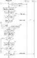
図4は、撮像装置100が行うネットワーク接続処理の手順を説明するためのフローチャートである。
FIG. 4 is a flowchart for explaining a procedure of network connection processing performed by the
本実施形態では、撮像装置100とFTP(File Transfer Protocol)サーバとして使用しているパーソナルコンピュータ500との間で画像を転送する処理が行われるものとする。なお、撮像装置100が使用する通信プロトコルとして、FTPの他にPTP(Picture Transfer Protocol)やHTTP(Hyper Txet Transfer Protocol)を用いてもよい。
In the present embodiment, it is assumed that processing for transferring an image is performed between the
まず、撮影者などのユーザが操作部115を操作し、撮像装置100に電源を投入する操作を行う。電源が投入されたことを検知すると(ステップS200)、システム制御部102は撮像装置100の初期化処理を実行する(ステップS202)。初期化の処理が終了すると、撮像装置100は、ユーザからの操作待ち状態となる。
First, a user such as a photographer operates the
ユーザは操作部115を操作し、撮像装置100がネットワーク400に接続するよう指示する。ユーザの指示を受け、撮像装置100は、既に記憶されている接続パラメータを用いた接続を行うか否かを選択させるためのGUIを表示部112に表示し、ユーザの選択を受け付ける。そしてユーザ操作による選択に基づき、システム制御部102は、既に記憶されている接続パラメータを用いた接続を行うか否かを判断する(ステップS203)。既に記憶されている接続パラメータを用いて接続する場合には処理をステップS210に進める。既に記憶されている接続パラメータを用いて接続しない場合には処理をステップS204に進める。
The user operates the
ステップS204において、システム制御部102は、ユーザ操作により新たな接続パラメータで接続する指示が行われたか否かを判断する。指示が行われた場合には処理をステップS205に進める。指示が行われなかった場合には処理をステップS208に進め、撮像装置100を通信機能を使わない撮像モードに設定する。
In step S204, the
ステップS205において、システム制御部102は、表示部112に接続パラメータ設定画面を表示し、ユーザ操作による各種接続パラメータの入力指示を受け付ける。システム制御部102は、入力された接続パラメータは揮発性メモリ110に記憶することで設定する。
In step S205, the
ステップS206において、システム制御部102はネットワークI/F106に電力を供給するよう制御する。
In step S <b> 206, the
ステップS207において、システム制御部102は、ステップS205で入力した接続パラメータを用いてネットワーク400への接続処理を行う。
In step S207, the
ステップS208において、システム制御部102は、ネットワーク400への接続が成功したか、すなわちネットワーク400との接続が確立したか否かを判断する。接続が確立した場合には処理をステップS209に進める。ネットワーク400への接続が確立しなかった場合、ステップS214において、ユーザに対して、接続が確立できなかった旨を通知する。そして、ステップS215において、ネットワークI/F106への電力の供給を停止する。接続が確立しない場合とは、例えばユーザにより入力された接続パラメータが誤っている場合である。
In step S208, the
以下、ネットワーク400への接続が確立された場合の処理について説明する。
Hereinafter, processing when a connection to the
ステップS209において、システム制御部102は、接続パラメータを参照し、DHCP機能を用いてDHCPサーバ600や600aなどから動的なIPアドレスを取得するよう設定されているか否かを判断する。DHCP機能を用いる場合、処理をステップS216に進める。DHCP機能を用いない場合、処理をステップS221に進める。
In step S209, the
ステップS216において、システム制御部102はDHCPサーバから送信されたIPアドレスなどを受信し、揮発性メモリ110に記憶する。
In step S <b> 216, the
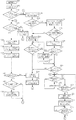
以下、撮像装置100がDHCPサーバからIPアドレスを受信する際の処理(ステップS216)について、図3のシーケンス図を用いて説明する。以下、撮像装置100はDHCPサーバ600aと通信するものとする。
Hereinafter, the process (step S216) when the
まずステップS101において、システム制御部102はDHCPサーバ600aに対し、IPアドレスの取得要求を送信する。
First, in step S101, the
ステップS102において、DHCPサーバ600aは撮像装置100にIPアドレスを割当て、IPアドレスを撮像装置100に送信する。
In step S <b> 102, the
ステップS103において、システム制御部102はIPアドレスを受信し、揮発性メモリ110に記憶する。
In step S <b> 103, the
ステップS104において、システム制御部102はRTC109を参照し、時間情報を取得する。そして取得した時間情報をIPアドレスを受信した時間(以下、「受信時間」)として揮発性メモリ110に記憶する。
In step S104, the
ステップS105において、DHCPサーバ600aは、IPアドレスのリース期間の情報を撮像装置100に送信する。このリース期間はDHCPサーバ600aにより決定される。なお、リース期間の送信は必ずしもこのタイミングである必要はなく、例えばステップS102においてIPアドレスと共に送信してもよい。
In step S105, the
ステップS106において、システム制御部102は、DHCPサーバ600aから受信したリース期間情報を揮発性メモリ110に記憶する。
In step S106, the
なお、本実施形態では受信時間を撮像装置100のRTC109から取得しているが、GPS(Global Positioning System)などから時間情報を取得してもよい。
In the present embodiment, the reception time is acquired from the
以上が、ステップS216における撮像装置100がDHCPサーバ600aからIPアドレスを受信する処理である。
The above is the process in which the
次に、IPアドレスを受信した撮像装置100が撮像処理を行い、撮像した画像を転送する処理について説明する。以下、図4のステップS221からの処理について説明する。
Next, a process in which the
ステップS221において、システム制御部102は転送の対象となる画像が発生したか否かを判断する。例えば、撮像処理により新たな画像が生成された場合にはその画像が転送の対象となる。発生したと判断した場合には処理をステップS222に進める。発生していないと判断した場合には処理をステップS223に進める。
In step S221, the
ステップS222において、システム制御部102は、ネットワークI/F106を介して、接続パラメータに設定されたFTPサーバ500、500aに画像を転送し(ステップS107)、処理をステップS221に戻す。
In step S222, the
ステップS223において、システム制御部102は、転送画像が存在しなくなってから一定時間が経過したか否かを判断する。すなわち、転送の対象となる画像が一定時間の間発生していないかを判断する。一定時間経過している場合には処理をステップS224に進める。一定時間経過していない場合には処理をステップS221に戻す。なお、この一定時間(以下、「スリープ移行時間」)は予め不揮発性メモリ111に記憶されているものとする。
In step S223, the
ステップS224以下の処理において、システム制御部102はスリープ状態への移行を開始する。スリープ状態とは省電力状態のひとつであり、撮像装置100自体の電源は停止せずに、電源部108からネットワークI/F106への電力供給を停止した状態をいう。
In the processing after step S224, the
ステップS224において、システム制御部102は、不揮発性メモリ111に記憶したリース期間及び受信時間を揮発性メモリ110に退避させる。
In step S <b> 224, the
そしてステップS225において、電源部108からネットワーク接続用I/Fの電力供給を停止し、スリープ状態となる。
In step S225, power supply from the
なお、撮像装置100自体の電源は停止されていないため、揮発性メモリ110への電力供給は停止されていない状態である。そのため、揮発性メモリ110に記憶された接続パラメータが消去されることはない。
Note that the power supply to the
次に、この状態から撮像装置100自体の電源が停止される場合について述べる。電源の停止処理はユーザ操作に基づき、図6のフロー中に割り込み処理として実行される。
Next, a case where the power supply of the
撮像装置100自体の電源が停止される場合には、ネットワークI/F106への電力供給だけでなく、揮発性メモリ110への電力供給も停止されてしまう状態になる(以下、「パワーセーブ状態」)。この場合にシステム制御部102は、揮発性メモリ110上に記憶していたリース期間情報及び受信時間を、不揮発性メモリ111に関連付けて記憶する。これは、撮像装置100自体の電源が停止されても接続パラメータが消去されないよう、揮発性メモリ110に記憶された情報を不揮発性メモリ111に記憶させるということである。
When the power supply of the
ここまで、撮像装置100がネットワークI/F106を備えている場合について説明してきた。しかし、必ずしも撮像装置100自体が通信機能を備える必要はない。例えば、通信機能を持たない撮像装置とネットワークI/Fを備えた装置(以下「ネットワーク装置」)とをコネクタやケーブルなどで接続することで、図2に示す構成を備えた撮像装置100と同様の機能を実現できる。
So far, the case where the
この場合には、ネットワーク装置は撮像装置100とは独立してパワーセーブ状態に移行することが可能である。したがって、ネットワーク装置がパワーセーブ状態に移行する場合には、ネットワーク装置の揮発性メモリに記憶された接続パラメータを撮像装置100の不揮発性メモリ111に記憶させることで、接続パラメータの消失を防ぐことができる。
In this case, the network apparatus can shift to the power saving state independently of the
以下、撮像装置100がスリープ状態(ステップS108)になった後の処理について説明する。
Hereinafter, processing after the
ステップS226において、システム制御部102は、画像を転送するための準備動作(以下、「準備動作」)が発生したか否かを判断する。発生したと判断した場合には処理をステップS210に進める。発生していないと判断した場合には発生するまで処理を繰り返す。
In step S226, the
ここで、準備動作(ステップS109)とは、ユーザ操作によりシャッタースイッチ101が押された場合や、表示部112に表示されたGUI画面上から、転送する画像を選択するモードに移行する操作が行われた場合などがある。
Here, the preparatory operation (step S109) refers to an operation for shifting to a mode for selecting an image to be transferred when the
ステップS210において、システム制御部102は、画像の転送処理が開始されるであろうと予測し、ネットワークI/F106への電力の供給を開始する。
In step S <b> 210, the
ステップS211において、システム制御部102は、リース期間が残っているか否かを判断する。以下、ステップS211の処理について図3を用いて詳しく説明する。
In step S211, the
準備動作が発生すると(ステップS109)、ステップS110においてシステム制御部102は、RTC109を参照し現在の時刻をスリープ状態からの復帰時間(以下、「復帰時間」)として揮発性メモリ110に記憶する。
When the preparation operation occurs (step S109), in step S110, the
ステップS111において、システム制御部102は、リース期間とIPアドレスを受信してからの経過時間とを比較する。具体的には、システム制御部102は揮発性メモリ110に記憶されているリース期間情報と受信時間を読み出す。次に復帰時間と受信時間の差を求めることで、IPアドレスを受信してからの経過時間を算出し、リース期間との比較を行う。
In step S111, the
ステップS112において、システム制御部102は、IPアドレスを受信してからの経過時間がリース期間よりも長いか否かを判断する。長いと判断された場合には処理をステップS101に戻す。長くないと判断された場合には処理をステップS113に進める。このステップS110〜S112の動作が図4のステップS211の処理に相当する。
In step S112, the
ステップS211で、IPアドレスを受信してからの経過時間がリース期間よりも短い場合、つまりリース期間が残っている場合について説明する。この場合は、既に揮発性メモリ110に記憶されているIPアドレスがまだ有効である。
A case where the elapsed time after receiving the IP address in step S211 is shorter than the lease period, that is, the case where the lease period remains will be described. In this case, the IP address already stored in the
したがって、ステップS218においてシステム制御部102は、揮発性メモリ110からIPアドレスを読み出し、ネットワーク400への接続を開始する(ステップS113、S218)。
Accordingly, in step S218, the
そしてステップS219において、システム制御部102は、ネットワーク400への接続が確立したか否かを判断する。確立したと判断した場合には処理をステップS220に進める。確立しなかったと判断した場合には処理をステップS213に進め、IPアドレスの再取得を行う。
In step S219, the
ステップS220において、システム制御部102においてFTPサーバ500aと接続が確立したか否かを判断する。確立したと判断した場合には処理をステップS221に進める。確立しなかったと判断した場合には処理をステップS214に進める。
In step S220, the
次に、IPアドレスを受信してからの経過時間がリース期間よりも長い場合、つまりステップS211でリース期間が切れていると判断された場合について説明する。この場合にはDHCPサーバ600aが、撮像装置100が使用していたIPアドレスを別のネットワーク機器に対して割り振っている可能性がある。この場合、撮像装置100が既に記憶されているIPアドレスを使用すると、IPアドレスの衝突が発生するおそれがある。
Next, the case where the elapsed time after receiving the IP address is longer than the lease period, that is, the case where it is determined in step S211 that the lease period has expired will be described. In this case, the
したがって、ステップS212において、システム制御部102は、IPアドレスの再取得を行う。取得の具体的な方法は図3のステップS101からS103で説明した。
Therefore, in step S212, the
ステップS213において、システム制御部102は、DHCPサーバ600aから新しいIPアドレスを受信できた否かを判断する。受信できた場合には処理をステップS216に進める。受信できなかった場合には処理をステップS214に進める。
In step S213, the
ステップS216、S217において、システム制御部102は、取得したIPアドレスと揮発性メモリ110に記憶された接続パラメータに基づき、FTPサーバ500aとの接続を確立する処理を開始する。
In steps S216 and S217, the
ステップS220において、システム制御部102は、FTPサーバ500aとの接続が確立したか否かを判断する。確立した場合には処理をステップS221に進め、スリープ状態に移行するか否かを判断する処理に入る。接続が確立しなかった場合には処理をステップS214に進める。
In step S220, the
上述したように、本実施形態によれば、撮像装置100に電源を投入後、最初の通信モードを設定したときにネットワーク接続を行うので、通信モードが設定されるまではネットワークに接続されることはなく電力消費を低減させることができる。
As described above, according to the present embodiment, since the network connection is performed when the first communication mode is set after the
さらに本実施例では、撮像装置がスリープ状態から復帰後、IPアドレスのリース期間とIPアドレスを取得してからの経過時間を比較し、リース期間が過ぎているときにサーバ装置からIPアドレスを再取得する構成とした。このことにより、スリープ状態から復帰後、常にDHCPサーバに接続する必要がなくなり、画像を転送するまでの時間を短縮することができる。また、DHCPサーバへのアクセス頻度が減少し、スループットが向上する。 Furthermore, in this embodiment, after the imaging apparatus returns from the sleep state, the IP address lease period is compared with the elapsed time from the acquisition of the IP address, and when the lease period expires, the IP address is restored from the server apparatus. It was set as the composition to acquire. Thus, it is not necessary to always connect to the DHCP server after returning from the sleep state, and the time until the image is transferred can be shortened. In addition, the frequency of access to the DHCP server is reduced and the throughput is improved.
さらに本実施例では、スリープ状態になりネットワークI/Fに電源が供給されていない期間も、IPアドレスを受信してからの経過時間として計算するようにした。このことにより、撮像装置がスリープ状態に入っていてもIPアドレスの有効性を正確に把握することができる。 Further, in the present embodiment, the period when the network I / F is in the sleep state and the power is not supplied is calculated as the elapsed time after receiving the IP address. This makes it possible to accurately grasp the validity of the IP address even when the imaging apparatus is in the sleep state.
<第2の実施形態>
次に、第2の実施形態について説明する。第1の実施形態における撮像装置は、IPアドレスを受信してからの経過時間がリース期間よりも長い、すなわちIPアドレスの残りの有効期間が既に切れている場合にIPアドレスを再取得する構成とした。しかし、IPアドレスの残りの有効期間が残り少ない場合には、予めIPアドレスを再取得しておく方が効率がよい。そこで本実施形態では、IPアドレスの残りの有効期間が閾値よりも短い場合にIPアドレスを再取得する構成とした。
<Second Embodiment>
Next, a second embodiment will be described. The imaging apparatus according to the first embodiment is configured to reacquire an IP address when the elapsed time after receiving the IP address is longer than the lease period, that is, when the remaining valid period of the IP address has already expired. did. However, when the remaining valid period of the IP address is small, it is more efficient to reacquire the IP address in advance. Therefore, in this embodiment, the IP address is reacquired when the remaining valid period of the IP address is shorter than the threshold.
なお、本実施形態は第1の実施形態と共通する部分が多い。したがって、共通の部分の説明は省略し、本実施形態に特有の部分を中心に説明する。 This embodiment has many parts in common with the first embodiment. Therefore, the description of the common part is omitted, and the part specific to the present embodiment will be mainly described.
本実施形態は、以下、DHCPサーバ600、600aから受信したIPアドレスとリース期間の取り扱いが第1の実施形態と異なる。以下、撮像装置100がDHCPサーバ600aからIPアドレスを受信する場合について図5及び図6を用いて説明する。
Hereinafter, the present embodiment differs from the first embodiment in the handling of the IP address and lease period received from the
本実施形態では、撮像装置100とFTP(File Transfer Protocol)サーバとして使用しているパーソナルコンピュータ500aとの間で画像の転送が行われるものとし、IPアドレスはDHCPサーバ600bから受信するものとする。
In the present embodiment, it is assumed that an image is transferred between the
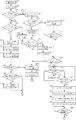
図6に示したフローのうち、第1の実施形態と異なる点は、ステップS218の前にステップS401とS402での処理を行う点である。以下、これらのステップにおける処理について説明する。 In the flow shown in FIG. 6, the difference from the first embodiment is that the processes in steps S401 and S402 are performed before step S218. Hereinafter, processing in these steps will be described.
図6のステップS211において、リース期間がIPアドレスを受信してからの経過時間がリース期間よりも短い場合、つまりリース期間が残っている場合、システム制御部102は処理をステップS401に進める。
In step S211, the
ステップS401において、システム制御部102は、スリープ移行時間を閾値として設定し、揮発性メモリ110に記憶する(ステップS301、S401)。ステップS402において、システム制御部102は、ステップS401で設定した閾値とリース期間の残り時間とを比較し、リース期間の残り時間がしきい値よりも長いか否かを判断する(ステップS302)。長い場合は処理をステップS218に進め、既に受信しているIPアドレスを用いてネットワーク400への接続を行う。長くない場合は処理をステップS213に進め、DHCPサーバ600aからIPアドレスを再取得する。リース期間の残り時間は、リース期間とIPアドレスを受信してからの経過時間の差を求めることで算出できる。
In step S401, the
以上述べたように、本実施形態ではリース期間の残り時間が閾値より短い場合には、まだリース期間が残っていてもIPアドレスを再取得する構成とした。このことにより、画像の転送処理の途中でIPアドレスの有効期限が切れてしまうことを未然に防ぐことができる。 As described above, in this embodiment, when the remaining time of the lease period is shorter than the threshold, the IP address is reacquired even if the lease period still remains. As a result, it is possible to prevent the IP address from expiring during the image transfer process.
また、閾値をスリープ移行時間に設定することで、スリープ状態への移行前にIPアドレスのリース期間が切れてしまうことを防ぐことが可能となる。 Further, by setting the threshold value to the sleep transition time, it is possible to prevent the lease period of the IP address from being expired before the transition to the sleep state.
その他に、撮像装置100で設定されている画像圧縮率やISO感度、転送する画像のファイル数などに基づき、画像を転送するのに要する予想時間を算出し、その時間情報を基に閾値を設定する方法も考えられる。
In addition, the expected time required to transfer the image is calculated based on the image compression rate and ISO sensitivity set in the
閾値を画像を転送するのに要する予想時間に設定することで、画像の転送中にIPアドレスの有効期限が切れてしまうことを防ぐことが可能となる。 By setting the threshold value to the expected time required to transfer the image, it is possible to prevent the expiration date of the IP address from being expired during the image transfer.
<第3の実施形態>
次に、第3の実施形態について説明する。
<Third Embodiment>
Next, a third embodiment will be described.
なお、本実施形態は第1の実施形態と共通する部分が多い。したがって、共通の部分の説明は省略し、本実施形態に特有の部分を中心に説明する。 This embodiment has many parts in common with the first embodiment. Therefore, the description of the common part is omitted, and the part specific to the present embodiment will be mainly described.
本実施形態は、以下、DHCPサーバ600、600aから受信したIPアドレスとリース期間の取り扱いが第1の実施形態と異なる。以下、撮像装置100がDHCPサーバ600aからIPアドレスを受信する場合について図7及び図8を用いて説明する。
Hereinafter, the present embodiment differs from the first embodiment in the handling of the IP address and lease period received from the
本実施形態では、撮像装置100とFTP(File Transfer Protocol)サーバとして使用しているパーソナルコンピュータ500aとの間で画像の転送が行われるものとし、IPアドレスはDHCPサーバ600aから受信するものとする。
In the present embodiment, it is assumed that an image is transferred between the
図8に示したフローのうち、第1の実施形態と異なる点は、ステップS224の前にステップS601とS602での処理を行う点である。以下、これらのステップにおける処理について説明する。 In the flow shown in FIG. 8, the difference from the first embodiment is that the processes in steps S601 and S602 are performed before step S224. Hereinafter, processing in these steps will be described.
図8のステップS223において、システム制御部102は、スリープ以降時間が経過したと判断した場合に処理をステップS601に進める。
In step S223 of FIG. 8, the
ステップS601において、システム制御部102は、DHCPサーバ600aから受信したIPアドレスを一旦開放する。具体的には、DHCPサーバ600aに対して、IPアドレスが不要になった旨を通知する。
In step S601, the
そしてステップS602において、システム制御部102がDHCPサーバ600aから再度新しいIPアドレスを受信してからスリープ状態に移行する。
In step S602, after the
そしてスリープ状態から復帰後、システム制御部102は、IPアドレスを受信してからの経過時間がリース期間よりも長いか否かを判断する(ステップS211、ステップS112)。リース期間の方が長いと判断すればスリープ状態に移行する直前に受信したIPアドレスを用いて接続を行う(ステップS218、ステップS504)。
Then, after returning from the sleep state, the
上記のように、本実施形態では、スリープ状態に移行する前にIPアドレスの開放及び再取得処理を行う構成とした。このことにより、スリープ状態から復帰したときにIPアドレスのリース期間が切れている可能性が少なくなり、起動時間を短縮して画像の転送を開始できる場合が多くなる。 As described above, in the present embodiment, the IP address release and reacquisition processing is performed before shifting to the sleep state. As a result, the possibility that the lease period of the IP address has expired when returning from the sleep state is reduced, and there are many cases where the transfer of the image can be started with the activation time shortened.
また、スリープ状態に移行する前にIPアドレスを開放することにより、DHCPサーバは開放されたIPアドレスを他の装置に割当てることができるため、IPアドレスを有効に活用することができる。 Also, by releasing the IP address before shifting to the sleep state, the DHCP server can assign the released IP address to another device, and therefore the IP address can be used effectively.
(他の実施形態)
本発明は、上述した実施形態1から3に係る撮像装置100の機能をプログラム化し、予めROMのような記録媒体に書き込んでおき、撮像装置にこのROMを装着して実行することによって、本発明の目的が達成されることは言うまでもない。
(Other embodiments)
In the present invention, the functions of the
この場合、ROMから読み出されて実行された状態が上述した実施の形態に係る機能を実現することになり、そのプログラムおよびそのプログラムを記録したROMも本発明を構成することになる。 In this case, the state read from the ROM and executed realizes the functions according to the above-described embodiment, and the program and the ROM storing the program also constitute the present invention.
なお、上述した実施の形態に係る撮像装置の機能を実現するプログラムは、記録媒体に記憶された形で提供されてもよい。記憶媒体は例えば半導体媒体(ROM、不揮発性メモリ等)、光媒体(DVD、MO、MD、CD等)、磁気媒体(磁気テープ、フレキシブルディスク等)を用いることができる。あるいは、ネットワーク等の通信網を介して記憶装置に格納された、上述したプログラムをサーバコンピュータから受信することで、プログラムの供給を受けるようにしてもよい。 The program that realizes the functions of the imaging device according to the above-described embodiment may be provided in a form stored in a recording medium. As the storage medium, for example, a semiconductor medium (ROM, nonvolatile memory, etc.), an optical medium (DVD, MO, MD, CD, etc.), and a magnetic medium (magnetic tape, flexible disk, etc.) can be used. Or you may make it receive supply of a program by receiving the program mentioned above stored in the memory | storage device via communication networks, such as a network, from a server computer.
100、100a、100b 撮像装置
101 シャッタースイッチ
102 システム制御部
103 圧縮伸長部
104 メモリカード
105 メモリカード
106 ネットワークI/F
107 主記憶メモリ
108 主電源
109 RTC
110 揮発性メモリ
111 不揮発性メモリ
112 表示部
113 カードI/F
114 カードI/F
115 操作部
116 センサ
200、200a アクセスポイント
300、300a、300b ルーター
400 ネットワーク網
500、500a パーソナルコンピュータ
600、600a サーバ装置
100, 100a,
107
110 Volatile memory 111
114 card I / F
DESCRIPTION OF
Claims (10)
前記外部機器との通信に用いるアドレス及び前記アドレスのリース期間を受信する受信手段と、
前記受信手段によるアドレスの受信から経過した時間と前記アドレスのリース期間とから、前記リース期間の残り時間を算出する算出手段と、
前記通信装置に供給する電力を制御することで、第1の状態と、前記第1の状態よりも供給する電力を少なくする第2の状態とを切り替える電力制御手段と、
データの送信に要する時間を予測し、予測された時間に基づき閾値を設定する設定手段と、
前記第2の状態から前記第1の状態に移行した際に、前記アドレスが有効か否か判断する判断手段とを有し、
前記判断手段は、前記リース期間の残り時間が前記設定手段により設定された閾値よりも長い場合には前記アドレスが有効であると判断し、
前記判断手段により前記アドレスが有効であると判断された場合は前記受信したアドレスを用いて通信を行い、前記アドレスが有効でないと判断された場合は前記受信手段により再度アドレスを受信することを特徴とする通信装置。 A communication device capable of communicating with an external device and transmitting / receiving data,
Receiving means for receiving an address used for communication with the external device and a lease period of the address;
Calculating means for calculating the remaining time of the lease period from the time elapsed since the reception of the address by the receiving means and the lease period of the address;
Power control means for switching between a first state and a second state in which less power is supplied than in the first state by controlling the power supplied to the communication device;
Setting means for predicting the time required for data transmission and setting a threshold based on the predicted time;
When the second state shifts to the first state, and a determination unit that the address to determine whether valid or not,
The determination means determines that the address is valid when the remaining time of the lease period is longer than a threshold set by the setting means;
It if said address is determined to be Ru effective der by the determining means performs communication using the address received; if the address is valid and Do the Most decision to receive again address by the receiving means A communication device characterized by the above.
前記電力制御手段は、前記撮像の指示が一定時間なかった場合に前記第1の状態から前記第2の状態への切り替えを行うことを特徴とする請求項1に記載の通信装置。 It further has an imaging means for imaging a subject and obtaining image data,
The communication apparatus according to claim 1 , wherein the power control unit performs switching from the first state to the second state when there is no instruction for imaging for a predetermined time.
前記アドレスが有効でない場合には、前記受信手段により再度アドレスを受信した後に前記電力制御手段による第2の状態への移行を行うことを特徴とする請求項1乃至6に記載の通信装置。 When the power control unit makes a transition from the first state to the second state, the determination unit determines whether the address is valid,
7. The communication apparatus according to claim 1, wherein, when the address is not valid, the power control unit shifts to the second state after receiving the address again by the receiving unit.
前記受信した時間情報から前記受信手段によるアドレスの受信から経過した時間を取得することを特徴とする請求項1乃至7に記載の通信装置。 A means for receiving time information from an external device;
8. The communication apparatus according to claim 1, wherein a time elapsed since the reception of the address by the receiving unit is acquired from the received time information.
前記外部機器と通信装置との通信に用いるアドレス及び前記アドレスのリース期間を受信する受信工程と、
前記受信工程におけるアドレスの受信から経過した時間と前記アドレスのリース期間とから、前記リース期間の残り時間を算出する算出工程と、
前記通信装置に供給する電力を制御することで、第1の状態と、前記第1の状態よりも供給する電力を少なくする第2の状態とを切り替える電力制御工程と、
データの送信に要する時間を予測し、予測された時間に基づき閾値を設定する設定工程と、
前記第2の状態から前記第1の状態に移行した際に、前記アドレスが有効か否か判断する判断工程とを有し、
前記判断工程では、前記リース期間の残り時間が前記設定工程において設定された閾値よりも長い場合には前記アドレスが有効であると判断し、
前記判断工程において前記アドレスが有効であると判断された場合は前記受信したアドレスを用いて通信を行い、前記アドレスが有効でないと判断された場合は再度アドレスを受信することを特徴とする通信装置の制御方法。 A communication device control method capable of communicating with an external device and transmitting / receiving data,
A receiving step of receiving an address used for communication between the external device and the communication device and a lease period of the address;
A calculation step of calculating a remaining time of the lease period from a time elapsed since the reception of the address in the reception step and a lease period of the address;
A power control step of switching between a first state and a second state in which less power is supplied than in the first state by controlling the power supplied to the communication device;
A setting process for predicting the time required for data transmission and setting a threshold based on the predicted time;
When a transition from said second state to said first state, and a determination step of said address to determine whether valid or not,
In the determining step, it is determined that the address is valid when the remaining time of the lease period is longer than the threshold set in the setting step,
If the address in the determining step is determined to Ru effective der communicates with an address thus received, characterized in that it receives the address again if the address is valid and Do the Most determined A method for controlling a communication device.
Priority Applications (2)
| Application Number | Priority Date | Filing Date | Title |
|---|---|---|---|
| JP2007040905A JP4928303B2 (en) | 2007-02-21 | 2007-02-21 | COMMUNICATION DEVICE, ITS CONTROL METHOD, PROGRAM |
| US12/034,136 US7779095B2 (en) | 2007-02-21 | 2008-02-20 | Apparatus for communicating with external apparatus, controlling method, and computer-readable storage medium |
Applications Claiming Priority (1)
| Application Number | Priority Date | Filing Date | Title |
|---|---|---|---|
| JP2007040905A JP4928303B2 (en) | 2007-02-21 | 2007-02-21 | COMMUNICATION DEVICE, ITS CONTROL METHOD, PROGRAM |
Publications (3)
| Publication Number | Publication Date |
|---|---|
| JP2008205925A JP2008205925A (en) | 2008-09-04 |
| JP2008205925A5 JP2008205925A5 (en) | 2010-04-08 |
| JP4928303B2 true JP4928303B2 (en) | 2012-05-09 |
Family
ID=39707593
Family Applications (1)
| Application Number | Title | Priority Date | Filing Date |
|---|---|---|---|
| JP2007040905A Expired - Fee Related JP4928303B2 (en) | 2007-02-21 | 2007-02-21 | COMMUNICATION DEVICE, ITS CONTROL METHOD, PROGRAM |
Country Status (2)
| Country | Link |
|---|---|
| US (1) | US7779095B2 (en) |
| JP (1) | JP4928303B2 (en) |
Families Citing this family (6)
| Publication number | Priority date | Publication date | Assignee | Title |
|---|---|---|---|---|
| JP4751461B2 (en) * | 2009-04-07 | 2011-08-17 | シャープ株式会社 | Printing apparatus, printing system, and print data deletion method |
| KR101584304B1 (en) | 2009-07-20 | 2016-01-11 | 삼성전자주식회사 | Apparatus and method for requesting contents |
| JP2012257016A (en) * | 2011-06-08 | 2012-12-27 | Panasonic Corp | Radio system |
| CN106170015A (en) * | 2016-07-26 | 2016-11-30 | 杭州迪普科技有限公司 | A kind of method and device of limiting concurrent session number |
| JP6824707B2 (en) | 2016-11-22 | 2021-02-03 | キヤノン株式会社 | Communication equipment, control methods and programs for communication equipment |
| WO2021095226A1 (en) * | 2019-11-15 | 2021-05-20 | 日本電信電話株式会社 | Edge switching system, edge switching device, edge switching method, and program |
Family Cites Families (7)
| Publication number | Priority date | Publication date | Assignee | Title |
|---|---|---|---|---|
| JP3725070B2 (en) * | 2001-12-21 | 2005-12-07 | 株式会社東芝 | Network system, router, host, prefix management method and IP address management method |
| JP2003274049A (en) * | 2002-03-19 | 2003-09-26 | Fuji Photo Film Co Ltd | Communication apparatus |
| JP2004007316A (en) * | 2002-06-03 | 2004-01-08 | Internatl Business Mach Corp <Ibm> | Program, controller, and control method |
| JP2005086263A (en) | 2003-09-04 | 2005-03-31 | Ricoh Co Ltd | Image imaging apparatus, network connection control method, program, and recording medium |
| JP4298530B2 (en) * | 2004-01-30 | 2009-07-22 | キヤノン株式会社 | Communication device |
| JP2006166324A (en) * | 2004-12-10 | 2006-06-22 | Canon Inc | Resume control method |
| JP2007036456A (en) * | 2005-07-25 | 2007-02-08 | Canon Inc | Information processing apparatus and network control method thereof |
-
2007
- 2007-02-21 JP JP2007040905A patent/JP4928303B2/en not_active Expired - Fee Related
-
2008
- 2008-02-20 US US12/034,136 patent/US7779095B2/en not_active Expired - Fee Related
Also Published As
| Publication number | Publication date |
|---|---|
| JP2008205925A (en) | 2008-09-04 |
| US7779095B2 (en) | 2010-08-17 |
| US20080201445A1 (en) | 2008-08-21 |
Similar Documents
| Publication | Publication Date | Title |
|---|---|---|
| JP4928303B2 (en) | COMMUNICATION DEVICE, ITS CONTROL METHOD, PROGRAM | |
| CN111083685B (en) | Data processing system, data processing method, and storage medium | |
| US20160227097A1 (en) | Data processing device that executes predetermined data processing by linking with other apparatus | |
| WO2013118487A1 (en) | Communication device | |
| WO2007007758A1 (en) | Electronic camera | |
| WO2007102046A1 (en) | Auto continuation/discontinuation of data download and upload when entering/leaving a network | |
| JP2007020037A (en) | Electronic camera | |
| JP6406801B2 (en) | Image forming apparatus, control method therefor, and program | |
| JP2006325145A (en) | Imaging apparatus and power source control method thereof | |
| US9807222B2 (en) | Communication apparatus, method of controlling same, and storage medium | |
| JP2011114583A (en) | Imaging apparatus, control method thereof, and program | |
| JP6869746B2 (en) | Communication device, its control method, program | |
| JP2008146250A (en) | Update system, update method, and program | |
| JP6463050B2 (en) | COMMUNICATION DEVICE, ITS CONTROL METHOD, AND PROGRAM | |
| US8310954B2 (en) | Apparatus and method for identifying network connection status in portable terminal | |
| JP4760174B2 (en) | Electronic camera | |
| JP4821195B2 (en) | Electronic camera | |
| JP2007020042A (en) | Electronic camera | |
| JP2012147357A (en) | Imaging apparatus | |
| JP2005086263A (en) | Image imaging apparatus, network connection control method, program, and recording medium | |
| JP5043706B2 (en) | COMMUNICATION DEVICE, COMMUNICATION METHOD, AND PROGRAM | |
| CN111263055B (en) | Image pickup apparatus, control method thereof, system, and computer-readable storage medium | |
| JP2019033539A (en) | Communication device, communication system, communication method, and program | |
| JP7155000B2 (en) | COMMUNICATION DEVICE, COMMUNICATION DEVICE CONTROL METHOD, AND PROGRAM | |
| CN117750544A (en) | Communication apparatus, communication method, communication system, and computer-readable storage medium |
Legal Events
| Date | Code | Title | Description |
|---|---|---|---|
| RD04 | Notification of resignation of power of attorney |
Free format text: JAPANESE INTERMEDIATE CODE: A7424 Effective date: 20100201 |
|
| A521 | Request for written amendment filed |
Free format text: JAPANESE INTERMEDIATE CODE: A523 Effective date: 20100219 |
|
| A621 | Written request for application examination |
Free format text: JAPANESE INTERMEDIATE CODE: A621 Effective date: 20100219 |
|
| RD01 | Notification of change of attorney |
Free format text: JAPANESE INTERMEDIATE CODE: A7421 Effective date: 20100630 |
|
| A977 | Report on retrieval |
Free format text: JAPANESE INTERMEDIATE CODE: A971007 Effective date: 20120130 |
|
| TRDD | Decision of grant or rejection written | ||
| A01 | Written decision to grant a patent or to grant a registration (utility model) |
Free format text: JAPANESE INTERMEDIATE CODE: A01 Effective date: 20120207 |
|
| A01 | Written decision to grant a patent or to grant a registration (utility model) |
Free format text: JAPANESE INTERMEDIATE CODE: A01 |
|
| A61 | First payment of annual fees (during grant procedure) |
Free format text: JAPANESE INTERMEDIATE CODE: A61 Effective date: 20120210 |
|
| FPAY | Renewal fee payment (event date is renewal date of database) |
Free format text: PAYMENT UNTIL: 20150217 Year of fee payment: 3 |
|
| R151 | Written notification of patent or utility model registration |
Ref document number: 4928303 Country of ref document: JP Free format text: JAPANESE INTERMEDIATE CODE: R151 |
|
| FPAY | Renewal fee payment (event date is renewal date of database) |
Free format text: PAYMENT UNTIL: 20150217 Year of fee payment: 3 |
|
| LAPS | Cancellation because of no payment of annual fees |