JP4926064B2 - Baroreflex modulation based on monitored cardiovascular parameters - Google Patents
Baroreflex modulation based on monitored cardiovascular parameters Download PDFInfo
- Publication number
- JP4926064B2 JP4926064B2 JP2007531174A JP2007531174A JP4926064B2 JP 4926064 B2 JP4926064 B2 JP 4926064B2 JP 2007531174 A JP2007531174 A JP 2007531174A JP 2007531174 A JP2007531174 A JP 2007531174A JP 4926064 B2 JP4926064 B2 JP 4926064B2
- Authority
- JP
- Japan
- Prior art keywords
- stimulation
- baroreflex
- various embodiments
- heart rate
- cardiovascular parameter
- Prior art date
- Legal status (The legal status is an assumption and is not a legal conclusion. Google has not performed a legal analysis and makes no representation as to the accuracy of the status listed.)
- Expired - Fee Related
Links
Images


Classifications
-
- A—HUMAN NECESSITIES
- A61—MEDICAL OR VETERINARY SCIENCE; HYGIENE
- A61N—ELECTROTHERAPY; MAGNETOTHERAPY; RADIATION THERAPY; ULTRASOUND THERAPY
- A61N1/00—Electrotherapy; Circuits therefor
- A61N1/18—Applying electric currents by contact electrodes
- A61N1/32—Applying electric currents by contact electrodes alternating or intermittent currents
- A61N1/36—Applying electric currents by contact electrodes alternating or intermittent currents for stimulation
- A61N1/3605—Implantable neurostimulators for stimulating central or peripheral nerve system
- A61N1/36128—Control systems
- A61N1/36135—Control systems using physiological parameters
- A61N1/36139—Control systems using physiological parameters with automatic adjustment
-
- A—HUMAN NECESSITIES
- A61—MEDICAL OR VETERINARY SCIENCE; HYGIENE
- A61N—ELECTROTHERAPY; MAGNETOTHERAPY; RADIATION THERAPY; ULTRASOUND THERAPY
- A61N1/00—Electrotherapy; Circuits therefor
- A61N1/18—Applying electric currents by contact electrodes
- A61N1/32—Applying electric currents by contact electrodes alternating or intermittent currents
- A61N1/36—Applying electric currents by contact electrodes alternating or intermittent currents for stimulation
- A61N1/3605—Implantable neurostimulators for stimulating central or peripheral nerve system
- A61N1/3606—Implantable neurostimulators for stimulating central or peripheral nerve system adapted for a particular treatment
- A61N1/36114—Cardiac control, e.g. by vagal stimulation
- A61N1/36117—Cardiac control, e.g. by vagal stimulation for treating hypertension
-
- A—HUMAN NECESSITIES
- A61—MEDICAL OR VETERINARY SCIENCE; HYGIENE
- A61N—ELECTROTHERAPY; MAGNETOTHERAPY; RADIATION THERAPY; ULTRASOUND THERAPY
- A61N1/00—Electrotherapy; Circuits therefor
- A61N1/18—Applying electric currents by contact electrodes
- A61N1/32—Applying electric currents by contact electrodes alternating or intermittent currents
- A61N1/36—Applying electric currents by contact electrodes alternating or intermittent currents for stimulation
- A61N1/3605—Implantable neurostimulators for stimulating central or peripheral nerve system
- A61N1/36053—Implantable neurostimulators for stimulating central or peripheral nerve system adapted for vagal stimulation
-
- A—HUMAN NECESSITIES
- A61—MEDICAL OR VETERINARY SCIENCE; HYGIENE
- A61N—ELECTROTHERAPY; MAGNETOTHERAPY; RADIATION THERAPY; ULTRASOUND THERAPY
- A61N1/00—Electrotherapy; Circuits therefor
- A61N1/18—Applying electric currents by contact electrodes
- A61N1/32—Applying electric currents by contact electrodes alternating or intermittent currents
- A61N1/36—Applying electric currents by contact electrodes alternating or intermittent currents for stimulation
- A61N1/3605—Implantable neurostimulators for stimulating central or peripheral nerve system
- A61N1/3606—Implantable neurostimulators for stimulating central or peripheral nerve system adapted for a particular treatment
- A61N1/36114—Cardiac control, e.g. by vagal stimulation
-
- A—HUMAN NECESSITIES
- A61—MEDICAL OR VETERINARY SCIENCE; HYGIENE
- A61N—ELECTROTHERAPY; MAGNETOTHERAPY; RADIATION THERAPY; ULTRASOUND THERAPY
- A61N1/00—Electrotherapy; Circuits therefor
- A61N1/18—Applying electric currents by contact electrodes
- A61N1/32—Applying electric currents by contact electrodes alternating or intermittent currents
- A61N1/36—Applying electric currents by contact electrodes alternating or intermittent currents for stimulation
- A61N1/362—Heart stimulators
- A61N1/365—Heart stimulators controlled by a physiological parameter, e.g. heart potential
- A61N1/36514—Heart stimulators controlled by a physiological parameter, e.g. heart potential controlled by a physiological quantity other than heart potential, e.g. blood pressure
-
- A—HUMAN NECESSITIES
- A61—MEDICAL OR VETERINARY SCIENCE; HYGIENE
- A61N—ELECTROTHERAPY; MAGNETOTHERAPY; RADIATION THERAPY; ULTRASOUND THERAPY
- A61N1/00—Electrotherapy; Circuits therefor
- A61N1/18—Applying electric currents by contact electrodes
- A61N1/32—Applying electric currents by contact electrodes alternating or intermittent currents
- A61N1/36—Applying electric currents by contact electrodes alternating or intermittent currents for stimulation
- A61N1/372—Arrangements in connection with the implantation of stimulators
- A61N1/37211—Means for communicating with stimulators
- A61N1/37235—Aspects of the external programmer
-
- A—HUMAN NECESSITIES
- A61—MEDICAL OR VETERINARY SCIENCE; HYGIENE
- A61N—ELECTROTHERAPY; MAGNETOTHERAPY; RADIATION THERAPY; ULTRASOUND THERAPY
- A61N1/00—Electrotherapy; Circuits therefor
- A61N1/18—Applying electric currents by contact electrodes
- A61N1/32—Applying electric currents by contact electrodes alternating or intermittent currents
- A61N1/36—Applying electric currents by contact electrodes alternating or intermittent currents for stimulation
- A61N1/362—Heart stimulators
- A61N1/3627—Heart stimulators for treating a mechanical deficiency of the heart, e.g. congestive heart failure or cardiomyopathy
Landscapes
- Health & Medical Sciences (AREA)
- Life Sciences & Earth Sciences (AREA)
- Public Health (AREA)
- Animal Behavior & Ethology (AREA)
- Veterinary Medicine (AREA)
- Engineering & Computer Science (AREA)
- Biomedical Technology (AREA)
- Nuclear Medicine, Radiotherapy & Molecular Imaging (AREA)
- Radiology & Medical Imaging (AREA)
- General Health & Medical Sciences (AREA)
- Cardiology (AREA)
- Heart & Thoracic Surgery (AREA)
- Neurology (AREA)
- Neurosurgery (AREA)
- Biophysics (AREA)
- Physiology (AREA)
- Hematology (AREA)
- Electrotherapy Devices (AREA)
Description
(優先権の主張)
2004年9月13日に提出され、本願明細書に参照で組み入れる米国特許出願第10/939544号に優先権の恩典を主張する。
(Claiming priority)
The benefit of priority is claimed in US patent application Ser. No. 10/939544, filed Sep. 13, 2004, which is incorporated herein by reference.
(関連出願の相互引用)
本出願は、2003年12月24日に提出され、その全文を本願明細書に参照で組み入れる「Automatic Baroreflex Modulation Based on Cardiac Activity」という表題の米国特許出願第10/746846号の一部継続出願である。
(Mutual citation of related applications)
This application is a continuation-in-part of US patent application Ser. No. 10 / 746,846, filed Dec. 24, 2003, entitled “Automatic Baroflex Modulation Based on Cardiac Activity”, which is incorporated herein by reference in its entirety. is there.
本出願は概して埋込可能な医学デバイスに関し、さらに特定すると望ましい心拍数を供給するための圧反射刺激の調節に関する。 The present application relates generally to implantable medical devices, and more particularly to adjusting baroreflex stimulation to provide a desired heart rate.
医学的な(複数の)治療を実施するための、心臓刺激装置などの長期持続性の電気刺激装置の埋込は知られている。心臓刺激装置の例はペースメーカなどの埋込可能な心臓律動管理(CRM)デバイス、埋込可能な心臓除細動器(ICD)、ぺーシングや除細動機能を果たすことが可能な埋込可能デバイスを含む。 Implantation of long-lasting electrical stimulators, such as cardiac stimulators, to perform medical treatment (s) is known. Examples of cardiac stimulators include implantable cardiac rhythm management (CRM) devices such as pacemakers, implantable cardiac defibrillators (ICD), implantable capable of pacing and defibrillation functions Includes devices.
CRMデバイスは、心臓律動の不調を治療するために選択された心室に電気刺激を供給する埋込可能なデバイスである。例えば、埋込可能なペースメーカは調子を合わせたぺーシングパルスで心臓をぺーシングするCRMデバイスである。適切に機能すれば、最少の心拍数を強制することによってペースメーカは代謝要求に合致するように心臓の不能を適切な律動にそれ自体をぺーシングするように補う。いくつかのCRMデバイスは収縮を協調させるために心臓の多様な区域に供給されるぺーシングパルスを同期させる。協調した収縮は十分な心拍出量を供給しながら心臓が効率的にポンプ動作することを可能にする。 A CRM device is an implantable device that provides electrical stimulation to a selected ventricle to treat a cardiac rhythm disorder. For example, an implantable pacemaker is a CRM device that paces the heart with a pacing pulse in tune. If functioning properly, by forcing a minimum heart rate, the pacemaker compensates for the inability of the heart to pace itself to the proper rhythm to meet metabolic demands. Some CRM devices synchronize pacing pulses delivered to various areas of the heart to coordinate contractions. Coordinated contractions allow the heart to pump efficiently while providing sufficient cardiac output.
心不全は、周辺組織の代謝要求に合致するために適したレベルよりも下に落ちかねない正常よりも低い心拍出量を心臓機能が引き起こす臨床的な症候群に関する。心不全は付随する静脈や肺血管の充血に起因する鬱血性心不全(CHF)として存在することもある。心不全は虚血性心疾患などの多様な病因に起因することもある。 Heart failure refers to a clinical syndrome in which cardiac function causes a lower than normal cardiac output that can drop below a level suitable to meet the metabolic demands of the surrounding tissue. Heart failure may also exist as congestive heart failure (CHF) due to concomitant venous or pulmonary vascular hyperemia. Heart failure can result from a variety of etiologies such as ischemic heart disease.
高血圧は心疾患や他の関連する心臓共存症の原因である。血管が収縮すると高血圧が生じる。結果として、流量を維持するために心臓はさらに高い血圧でさらに過酷な動作をし、これが心不全の原因になりかねない。ペースメーカまたは除細動器を埋め込まれた大部分の一般の人や大部分の患者は高血圧の悩みを有する。血圧と高血圧を下ることが可能であれば長期的な死亡率と生活の質がこれらの人々に関して改善されるであろう。高血圧症を患っている多くの患者は生活スタイルの変更に関係する治療などの治療や高血圧薬剤に対応しない。 Hypertension is the cause of heart disease and other related heart comorbidities. Hypertension occurs when blood vessels contract. As a result, the heart operates more severely at higher blood pressures to maintain flow, which can lead to heart failure. Most common people and most patients implanted with pacemakers or defibrillators suffer from high blood pressure. Long-term mortality and quality of life will be improved for these people if blood pressure and high blood pressure can be lowered. Many patients with hypertension do not respond to treatments related to lifestyle changes or hypertension drugs.
圧受容性の領域または場は血圧の変化などの圧力の変化を感知することができる。圧受容体領域は本願明細書では圧受容器と称され、これは概して圧力変化のいずれのセンサも含む。例えば、圧受容器は求心性神経を含み、上昇した内部の血圧から結果として生じる壁の伸張に敏感であって中枢反射メカニズムの受容体(これが圧力を下げる傾向を有する)として機能する感覚神経終末をさらに含む。圧反射は負フィードバック・システムとして機能し、圧受容器の刺激によってトリガをかけられる反射メカニズムに関連する。上昇した圧力が血管を拡張させ、これが次には管壁の圧受容器を活性化する。圧受容器の活性化は、内部圧力と動脈壁の拡張を通じて自然に生じ、交感神経活動(SNA)の圧反射阻害と全身動脈圧の低下を引き起こす。圧受容器活性の上昇はSNAの低下を誘発し、これが末梢血管抵抗を下げることによって血圧を下げる。 A baroreceptive region or field can sense pressure changes, such as changes in blood pressure. The baroreceptor region is referred to herein as a baroreceptor, which generally includes any sensor of pressure change. For example, baroreceptors contain afferent nerves that are sensitive to wall stretching resulting from elevated internal blood pressure and function as sensory nerve endings that act as receptors for central reflex mechanisms (which tend to lower pressure). In addition. The baroreflex functions as a negative feedback system and is associated with a reflex mechanism triggered by baroreceptor stimulation. The increased pressure dilates the blood vessel, which in turn activates the baroreceptors on the tube wall. Baroreceptor activation occurs naturally through internal pressure and arterial wall dilation, causing baroreflex inhibition of sympathetic nerve activity (SNA) and a reduction in systemic arterial pressure. Increased baroreceptor activity induces a decrease in SNA, which lowers blood pressure by reducing peripheral vascular resistance.
圧受容器から導かれる求心性神経幹の刺激の一般的概念は知られている。例えば、直接的電気刺激が迷走神経と頸動脈洞に加えられてきた。頸動脈洞神経の電気刺激が結果として実験的高血圧の低下につながること、および頸動脈洞自体の圧受容性領域への直接的電気刺激が実験的高血圧における反射の低下をもたらすことを研究が示した。 The general concept of stimulation of afferent nerve trunks derived from baroreceptors is known. For example, direct electrical stimulation has been applied to the vagus nerve and carotid sinus. Studies show that electrical stimulation of the carotid sinus nerve results in a decrease in experimental hypertension and that direct electrical stimulation to the baroreceptive region of the carotid sinus itself results in a decrease in reflexes in experimental hypertension It was.
生活スタイルの変化を含む治療や高血圧薬剤に対応しない患者の高血圧を治療し、他の患者に対する薬剤依存性を減少させる可能性ための電気システムが提案されてきた。 Electrical systems have been proposed to treat therapies that include lifestyle changes and to treat hypertension in patients who do not respond to hypertensive drugs and to reduce drug dependence on other patients.
本主題事項の様々な態様や実施態様はモニタされた心臓血管パラメータを、圧受容器刺激を自動的に調節するために使用する。モニタされた心臓血管パラメータを使用することによって、心拍数などに標的化された効果を与えるために埋込可能な神経刺激装置が神経刺激供給を制御することができる。 Various aspects and embodiments of the present subject matter use monitored cardiovascular parameters to automatically adjust baroreceptor stimulation. By using the monitored cardiovascular parameters, an implantable neural stimulation device can control the neural stimulation delivery to provide a targeted effect such as heart rate.
本主題事項の態様は圧反射刺激を供給するためのシステムに関する。このシステムの実施態様は心拍数を感知して心拍数の指標となる信号を供給するための心拍数モニタを有し、かつ圧反射刺激装置を有する。この刺激装置は、圧反射療法のための圧反射刺激を供給するための刺激信号を間欠的に発生するパルス発生器を有し、さらに、刺激信号が望ましい心拍数に対応する望ましい圧反射刺激を供給するように心拍数の指標となる信号に基づいて刺激信号を調節するためのモジュレータを有する。 An aspect of the present subject matter relates to a system for providing baroreflex stimulation. An embodiment of this system has a heart rate monitor for sensing heart rate and providing a signal indicative of heart rate, and has a baroreflex stimulator. The stimulation device has a pulse generator that intermittently generates a stimulation signal for supplying baroreflex stimulation for baroreflex therapy, and further provides a desired baroreflex stimulation corresponding to the desired heart rate. A modulator is provided for adjusting the stimulation signal based on a signal indicative of a heart rate to be supplied.
このシステムの実施態様は圧反射刺激装置、心臓血管パラメータ・モニタ、コンパレータを有する。圧反射刺激装置は圧反射療法のために間欠的な圧反射刺激を供給するように刺激信号を発生するためのパルス発生器を有し、刺激信号を調節するためのモジュレータをさらに有する。心臓血管パラメータ・モニタは少なくとも1つの心臓血管パラメータをモニタし、圧反射刺激の間のこの心臓血管パラメータの指標となる第1の信号と圧反射刺激以外のときのこの心臓血管パラメータの指標となる第2の信号を供給するように構成される。コンパレータは心臓血管パラメータに関して第1と第2の信号に基づいて検出される変化を供給し、心臓血管パラメータに関する望ましい変化と検出された変化に基づいて治療制御信号を供給するように構成される。 This system embodiment includes a baroreflex stimulator, a cardiovascular parameter monitor, and a comparator. The baroreflex stimulation device has a pulse generator for generating a stimulation signal to provide intermittent baroreflex stimulation for baroreflex therapy, and further includes a modulator for adjusting the stimulation signal. The cardiovascular parameter monitor monitors at least one cardiovascular parameter and provides a first signal indicative of this cardiovascular parameter during baroreflex stimulation and an indication of this cardiovascular parameter when other than baroreflex stimulation. It is configured to provide a second signal. The comparator is configured to provide a detected change based on the first and second signals with respect to the cardiovascular parameter and to provide a therapy control signal based on the desired change and the detected change with respect to the cardiovascular parameter.
本主題事項の態様は埋込可能な医学デバイスを動作させるための方法に関する。この方法の実施態様では、圧反射刺激は、ある期間にわたって間欠的に圧反射療法のために供給される。検出されたフィードバック変化を供給するために、圧反射刺激が加えられるときと、その後の圧反射刺激が加えられないときとに、少なくとも1つの心臓血管フィードバック・パラメータに関する値を比較する。比較結果を供給するために、検出されたフィードバック変化が望ましいフィードバック変化と比較される。ある期間にわたって圧反射療法を制御するためにこの比較に基づいて圧反射刺激が調節される。 An aspect of the present subject matter relates to a method for operating an implantable medical device. In an embodiment of this method, baroreflex stimulation is provided for baroreflex therapy intermittently over a period of time. To provide a detected feedback change, a value for at least one cardiovascular feedback parameter is compared when a baroreflex stimulus is applied and when no subsequent baroreflex stimulus is applied. To provide a comparison result, the detected feedback change is compared to the desired feedback change. Based on this comparison, baroreflex stimulation is adjusted to control baroreflex therapy over a period of time.
この概要は本出願のいくつかの教示の総覧であり、本主題事項の排他的または網羅的な処置であるように意図されていない。本主題事項についてのさらなる詳細は詳細な説明や添付の特許請求の範囲に見出される。以下の詳細な説明を読んで理解し、その一部分を形成する図面類(これらの各々は限定の意味にとられるべきではない)を眺めると他の複数の態様は当業者に明らかであろう。本発明の範囲は添付の特許請求の範囲およびその同等物により定義される。 This summary is an overview of some teachings of the present application and is not intended to be an exclusive or exhaustive treatment of the present subject matter. Further details about the present subject matter are found in the detailed description and appended claims. Other aspects will be apparent to those skilled in the art upon reading and understanding the following detailed description, and viewing the drawings that form a part thereof, each of which should not be taken in a limiting sense. The scope of the present invention is defined by the appended claims and their equivalents.
本主題事項の以下の詳細な説明は、本主題事項が実践され得る特定の態様や実施形態を例示として示す添付の図面類を参照する。これらの実施形態は当業者が本主題事項を実践することを可能にするように十分に詳しく述べられる。本主題事項の範囲から逸脱することなく他の実施形態が利用されることが可能であり、構造的、理論的、電気的に変更することができる。この開示の中の「ある」、「1つの」、または「様々な」実施形態への参照は必ずしも同じ実施形態でなく、そのような参照は複数の実施形態を意図する。したがって以下の詳細な説明は限定の意味にとられるべきでなく、その範囲は添付の特許請求の範囲、同様にそのような特許請求の範囲が表題とされる適法な同等物の全範囲によってのみ定義される。 The following detailed description of the subject matter refers to the accompanying drawings that illustrate, by way of illustration, specific aspects and embodiments in which the subject matter may be practiced. These embodiments are described in sufficient detail to enable those skilled in the art to practice the subject matter. Other embodiments may be utilized and structural, theoretical, and electrical changes may be made without departing from the scope of the present subject matter. References to “an”, “one”, or “various” embodiments in this disclosure are not necessarily the same embodiment, and such references contemplate multiple embodiments. The following detailed description is, therefore, not to be taken in a limiting sense, and is limited only by the scope of the appended claims, as well as the full scope of legal equivalents headed by such claims. Defined.
(高血圧と圧反射生理学)
読者がこの開示を理解するのを手助けするために、高血圧と圧反射に関する生理学の簡単な考察が行われる。この簡単な考察は高血圧、自律神経系、圧反射を紹介する。
(High blood pressure and baroreflex physiology)
To help the reader understand this disclosure, a brief discussion of physiology related to hypertension and baroreflex is made. This brief discussion introduces hypertension, autonomic nervous system, baroreflex.
高血圧は心疾患や他の関連する心臓共存症の原因である。高血圧は概して、心臓血管の損傷または他の有害な結末を誘発し易いレベルへの、全身動脈血圧の一時的または持続的な上昇などの高い血圧に関し、高血圧は140mmHgを超える最高血圧または90mmHgを超える最低血圧として独断的に定義されてきた。血管が収縮すると高血圧が生じる。結果として、流量を維持するために心臓はさらに高い血圧でさらに過酷な動作をする。無制御の高血圧の結末は、限定はされないが網膜血管の疾病と卒中、左心室の肥大と不全、心筋梗塞、解離性動脈瘤、腎血管性疾患を含む。 Hypertension is the cause of heart disease and other related heart comorbidities. Hypertension generally relates to high blood pressure, such as a temporary or sustained rise in systemic arterial blood pressure, to a level that is prone to induce cardiovascular damage or other adverse consequences, and hypertension is above 140 mmHg or above 90 mmHg It has been arbitrarily defined as diastolic blood pressure. Hypertension occurs when blood vessels contract. As a result, the heart operates more severely at higher blood pressures to maintain flow. The consequences of uncontrolled hypertension include, but are not limited to, retinal vascular disease and stroke, left ventricular hypertrophy and failure, myocardial infarction, dissecting aneurysm, and renovascular disease.
自律神経系(ANS)は「不随意の」器官を制御し、その一方で随意(骨格)筋の収縮は体性運動神経によって制御される。不随意器官の範例は呼吸器官と消化器官を含み、血管と心臓もやはり含む。しばしばANSは、例えば分泌腺を制御するため、皮膚、眼球、胃、腸、膀胱の筋肉を制御するため、および心筋と血管周囲の筋肉を制御するために不随意で反射的な様式で機能する。 The autonomic nervous system (ANS) controls “involuntary” organs, while the contraction of voluntary (skeletal) muscles is controlled by somatic motor nerves. Examples of involuntary organs include respiratory and digestive organs, and also blood vessels and the heart. Often ANS functions in an involuntary and reflexive manner, for example, to control secretory glands, to control muscles of the skin, eyeballs, stomach, intestines, bladder, and to control myocardium and perivascular muscles .
ANSは、限定はされないが交感神経系と副交感神経系を含む。交感神経系はストレスと緊急事態に対する「闘争反応または高揚反応」と関係付けられる。効果の中でもとりわけ、「闘争反応または高揚反応」は血圧と心拍数を上げて骨格筋の血流量を増大させ、「闘争または逃亡」のためのエネルギーを供給するための消化を低下させる。副交感神経系は弛緩および「休養と消化応答」と関係付けられ、これは効果の中でもとりわけ血圧と心拍数を下げ、エネルギーを貯蔵するための消化を高める。ANSは正常な内部機能を維持し、体性神経系と共に作用する。 ANS includes, but is not limited to, the sympathetic and parasympathetic nervous systems. The sympathetic nervous system is associated with a “fighting or uplifting response” to stress and emergencies. Among other effects, a “struggle response or uplift response” increases blood pressure and heart rate to increase skeletal muscle blood flow and reduce digestion to provide energy for “struggle or escape”. The parasympathetic nervous system is associated with relaxation and “rest and digestive response”, which, among other effects, lowers blood pressure and heart rate and increases digestion to store energy. The ANS maintains normal internal function and works with the somatic nervous system.
本開示の主題事項は概して心拍数と血圧に対してANSが有する効果に言及し、血管拡張と血管収縮を含む。心拍数と力は交感神経系が刺激されると高められ、交感神経系が抑制される(副交感神経系が刺激される)と下げられる。図1Aと1Bは末梢血管制御のための神経メカニズムを図示している。図1Aは血管運動中枢への求心性神経を概して図示している。求心性神経はインパルスを神経中枢に向けて運ぶ。血管運動中枢は血管のサイズを制御するために血管を拡張し、収縮させる神経に関係する。図1Bは血管運動中枢からの遠心性神経をほぼ図示している。遠心性神経はインパルスを神経中枢から運び出す。 The subject matter of this disclosure generally refers to the effects ANS has on heart rate and blood pressure and includes vasodilation and vasoconstriction. Heart rate and power are increased when the sympathetic nervous system is stimulated and lowered when the sympathetic nervous system is suppressed (the parasympathetic nervous system is stimulated). 1A and 1B illustrate neural mechanisms for peripheral vascular control. FIG. 1A generally illustrates afferent nerves to the vasomotor center. Afferent nerves carry impulses toward the nerve center. The vasomotor center is concerned with nerves that dilate and contract blood vessels to control the size of the blood vessels. FIG. 1B schematically illustrates efferent nerves from the vasomotor center. Efferent nerves carry impulses out of the nerve center.
系統的と副交感神経系の刺激は心拍数と血圧以外の影響を有する。例えば、交感神経系の刺激は瞳孔を拡張させ、唾液と粘液の産生を減少させ、気管支の筋肉を弛緩させ、胃の不随意収縮(ぜん動)の連続的波動と胃の運動性を減少させ、肝臓によるグリコーゲンのグルコースへの変換を増大させ、腎臓による尿分泌を減少させ、膀胱の壁を弛緩させて括約筋を締める。副交感神経系の刺激(交感神経系の抑制)は瞳孔を収縮させ、唾液と粘液の産生を増加させ、気管支の筋肉を収縮させ、胃や大腸における分泌と運動性を高め、小腸における消化を高め、尿の分泌を増加させ、膀胱の壁を収縮させて括約筋を弛緩させる。交感神経系と副交感神経系に付随する機能は多く、複雑に互いに結び付いている可能性が高い。したがって、1つの生理学的システムにおける血管拡張などの所望の応答を達成するための交感神経系および/または副交感神経系の無差別の刺激は結果として他の生理学的システムにおける望ましくない応答につながる可能性が高い。 Systematic and parasympathetic stimulation has effects other than heart rate and blood pressure. For example, stimulation of the sympathetic nervous system dilates the pupil, reduces saliva and mucus production, relaxes bronchial muscles, reduces the continuous wave of involuntary contraction (peristalsis) and gastric motility, Increases the conversion of glycogen to glucose by the liver, decreases urine secretion by the kidneys, relaxes the bladder wall and tightens the sphincter. Stimulation of the parasympathetic nervous system (suppression of the sympathetic nervous system) contracts the pupil, increases saliva and mucus production, contracts the bronchial muscles, increases secretion and motility in the stomach and large intestine, and increases digestion in the small intestine Increases urine secretion, contracts the bladder wall and relaxes the sphincter. There are many functions associated with the sympathetic nervous system and the parasympathetic nervous system, and there is a high possibility that they are complexly linked to each other. Thus, indiscriminate stimulation of the sympathetic and / or parasympathetic nervous system to achieve a desired response, such as vasodilation in one physiological system, can result in undesirable responses in other physiological systems. Is expensive.
圧反射は圧受容器の刺激によってトリガをかけられる反射である。圧受容器は心臓の耳介の壁、心臓の脂肪体、大静脈、大動脈弓、頸動脈洞における感覚神経終末などのいずれの圧力変化のセンサも含み、増大した内部の圧力から結果として生じる壁の拡張に敏感であり、圧力を下げる傾向を有する中枢反射メカニズムの受容体として機能する。付け加えると、圧受容器は感覚神経終末からつながる迷走神経、大動脈神経、頸動脈神経などの求心性神経幹を含む。圧受容器の刺激は交感神経の活性を抑制(副交感神経系を刺激)し、末梢血管抵抗と心臓の収縮性を下げることによって全身動脈圧を減少させる。圧受容器は内部圧力と動脈壁の拡張によって自然に刺激される。 A baroreflex is a reflex triggered by baroreceptor stimulation. Baroreceptors include any pressure change sensors such as the heart auricular wall, heart fat pad, vena cava, aortic arch, and sensory nerve endings in the carotid sinus, resulting in increased wall pressure resulting from increased internal pressure. It functions as a receptor for central reflex mechanisms that are sensitive to dilation and have a tendency to reduce pressure. In addition, baroreceptors include afferent nerve trunks such as the vagus, aortic, and carotid nerves that connect from sensory nerve endings. Baroreceptor stimulation suppresses sympathetic activity (stimulates the parasympathetic nervous system) and reduces systemic arterial pressure by reducing peripheral vascular resistance and heart contractility. Baroreceptors are naturally stimulated by internal pressure and arterial wall dilation.
本主題事項のいくつかの態様は、神経系の見境のない刺激の望ましくない影響を減少させる一方で望ましい応答(例えば低下した高血圧)を刺激することを目的として、求心性神経幹を刺激するのではなく動脈壁の特定の神経終末を局所的に刺激する。例えば、いくつかの実施形態は肺動脈の圧受容器部位を刺激する。本主題事項のいくつかの実施形態は大動脈、心室、心臓の脂肪体の圧受容器または神経終末のどちらかの刺激を含み、本主題事項のいくつかの実施形態は迷走神経、頸動脈神経、大動脈神経などの求心性神経幹の刺激を含む。いくつかの実施形態はカフ電極を使用して求心性神経幹を刺激し、いくつかの実施形態は、電気刺激が管壁を貫通して求心性神経幹を刺激するように神経近傍の血管内に配置された血管内のリード線を使用して求心性神経幹を刺激する。 Some aspects of the present subject matter stimulate the afferent nerve trunk for the purpose of stimulating a desired response (eg, reduced hypertension) while reducing the undesirable effects of unapproved stimulation of the nervous system. Instead, it stimulates specific nerve endings in the arterial wall locally. For example, some embodiments stimulate baroreceptor sites in the pulmonary artery. Some embodiments of the present subject matter include stimulation of either the aorta, ventricle, cardiac fat pad baroreceptors or nerve endings, and some embodiments of the present subject matter include the vagus nerve, carotid nerve, aorta Includes stimulation of afferent nerve trunks such as nerves. Some embodiments use cuff electrodes to stimulate the afferent nerve trunk, and some embodiments intravascular near the nerve so that electrical stimulation penetrates the vessel wall to stimulate the afferent nerve trunk. Stimulate the afferent nerve trunk using intravascular leads placed in the.
図2A〜2Cは心臓を説明している。図2Aに図示されるように、心臓201は上大静脈202、大動脈弓203、肺動脈204を有し、図3〜5の図に付随する脈絡関係を供給するために有用である。下記でさらに詳しく考察されるように、肺動脈204は圧受容器を有する。心臓ペースメーカのリード線と同様に末梢静脈を通し、三尖弁を通して右心室の中にリード線が血管内挿入され(図中に明確に示されていない)、右心室から肺動脈弁を通って肺動脈の中へと続く。肺動脈と大動脈の一部は互いに近接している。様々な実施形態が肺動脈に血管内配置されたリード線を使用して大動脈内の圧受容器を刺激する。したがって、本主題事項の様々な実施形態によると、圧反射は肺動脈に血管内挿入された少なくとも1つの電極によって肺動脈の中または付近で刺激される。別法として、圧力感知能力を備えるかまたは備えない無線刺激デバイスがカテーテルを介して肺動脈の中に配置されることもある。刺激および/または刺激のためのエネルギーの制御は別の埋込可能または外部のデバイスによって超音波、電磁作用またはこれらの組合せを介して供給されてもよい。本主題事項の態様は肺動脈の中に圧受容器刺激装置を血管内埋め込むための相対的に無侵襲の外科技術を提供する。
2A-2C illustrate the heart. As illustrated in FIG. 2A, the
図2B〜2Cは心臓の右側と左側をそれぞれ図示しており、圧受容器部位として機能する神経終末を有する心臓脂肪体をさらに図示している。図2Bは右心房267、右心室268、洞結節269、上大静脈202、下大静脈270、大動脈271、右肺静脈272、右肺動脈273を図示している。図2Bはまた、上大静脈と大動脈の間の心臓脂肪体274も図示している。心臓脂肪体274内の圧受容器神経終末は、いくつかの実施形態では脂肪体の中に入れられた電極を使用して刺激され、いくつかの実施形態では例えば右肺動脈または上大静脈などの血管内で脂肪体の近傍に位置付けられて血管内供給されたリード線を使用して刺激される。図2Cは左心房275、左心室276、右心房267、右心室268、上大静脈202、下大静脈270、大動脈271、右肺静脈272、左肺静脈277、右肺動脈273、冠状静脈洞278を図示している。図2Cはまた、右心臓静脈近傍に位置する心臓脂肪体279と、下大静脈と左心房近傍に位置する心臓脂肪体280も図示している。脂肪体279内の圧受容器神経終末は、いくつかの実施形態では脂肪体279の中に入れられた電極を使用して刺激され、いくつかの実施形態では例えば右肺動脈273または右肺静脈272などの血管内で脂肪体の近傍に位置付けられて血管内供給されたリード線を使用して刺激される。280内の圧受容器は、いくつかの実施形態では脂肪体の中に入れられた電極を使用して刺激され、いくつかの実施形態では例えば下大静脈270または冠状静脈洞などの血管内で脂肪体の近傍に位置付けられて血管内供給されたリード線、または左心房275内のリード線を使用して刺激される。
2B-2C illustrate the right and left sides of the heart, respectively, further illustrating a cardiac fat pad with nerve endings that function as baroreceptor sites. FIG. 2B illustrates
図3は頸動脈洞305、大動脈弓303、肺動脈304の区域の圧受容器を図示している。大動脈弓303と肺動脈304は図2Aの心臓との関連で前に図示された。図3に図示されるように、迷走神経306が延び、大動脈弓303内、頸動脈洞305内、総頸動脈310内の圧受容器として機能する感覚神経終末307となっている。舌咽神経308は頸動脈洞305内の圧受容器として機能する神経終末309となる。これらの神経終末307、309は、例えば、上昇した内部の圧力から結果として生じる壁の拡張に敏感である。これらの神経終末の活性化が圧力を下げる。図には描かれていないが、心臓の脂肪体や心臓の心房と心室は圧受容器もやはり有する。カフは圧受容器から血管運動中枢へとつながって圧反射を刺激する迷走神経などの求心性神経幹の周囲に置かれてきた。本主題事項の様々な実施形態によると、求心性神経幹は求心性神経の近傍の血管に位置付けられたカフまたは血管内供給されたリード線を使用して刺激される。
FIG. 3 illustrates baroreceptors in the areas of the
図4は肺動脈404内と周囲の圧受容器を図示している。上大静脈402と大動脈弓403もやはり図示されている。図示されたように、肺動脈404は暗い区域で概して示されるようにいくつかの圧受容器411を有する。さらに、密な間隔の圧受容器の集団が動脈管索412の結合部付近に位置する。図4はまた、心臓の右心室413を示し、かつ右心室413を肺動脈404から隔てる肺動脈弁414を示している。本主題事項の様々な実施形態によると、肺動脈の中および/または付近の圧受容器を刺激するためにリード線が、末梢静脈を通して挿入され、三尖弁を通って右心室の中へ、かつ右心室413から肺動脈弁414を通って肺動脈404の中へと縫うように進められる。様々な実施形態で、例えば、リード線は動脈管索412付近の圧受容器の集団を刺激するように位置決めされる。図5は大動脈弓503内、動脈管索の近傍、肺動脈504の幹の圧受容器領域512を示している。いくつかの実施形態は図2B〜2Cに図示されるような大動脈および/または脂肪体にある圧受容器部位を刺激するようにリード線を肺動脈内で位置決めする。
FIG. 4 illustrates baroreceptors in and around the
図6は左大動脈神経が刺激されるときの呼吸615と血圧616の間の知られている関係を示す。617で神経が刺激されると、血圧616が降下し、呼吸波形のさらに高い周波数と振幅で図示されるように呼吸615がさらに速く、かつ深くなる。刺激が取り除かれると約1から2分後に呼吸と血圧は刺激前の状態に戻るように見える。本主題事項の様々な実施形態は、呼吸を血圧の代理パラメータとして使用することによって呼吸と血圧の間のこの関係を使用する。
FIG. 6 shows the known relationship between
図7は間欠的な頸動脈刺激を与えた6ヶ月の間の高血圧のイヌの頸動脈神経刺激に対する知られている血圧応答を示している。この図は刺激を受けたイヌの血圧718がやはり高い血圧を有する比較対照のイヌの血圧719よりも有意に低いことを示している。このようにして、間欠的な刺激は高い血圧を下げるように圧反射にトリガをかけることが可能である。
FIG. 7 shows the known blood pressure response to carotid nerve stimulation in a hypertensive dog during 6 months given intermittent carotid stimulation. This figure shows that the
(圧反射刺激システム)
本主題事項の様々な実施形態は圧反射刺激システムに関する。そのような圧反射刺激システムは本願明細書では神経刺激(NS)デバイスまたは部品とも称される。神経刺激装置の例は高血圧を治療するために使用される抗高血圧(AHT)デバイスまたはAHT部品を含む。本主題事項の様々な実施形態は独立型の埋込可能な圧受容器刺激システムを含み、NSを集積化した埋込可能なデバイスと心調律管理(CRM)部品を含み、無線またはリード線で接続する埋込可能なデバイスのどちらかで互いに通信することが可能な少なくとも1つの埋込可能なNSデバイスと埋込可能なCRMデバイスとを備えたシステムを含む。同じデバイスまたは別々のデバイスのどちらかで実行されるNS機能とCRM機能の集積化は、NS療法と心臓治療が一緒に知能的に作用することを可能にすることによってこれらの治療の態様を向上させる。
(Baroreflex stimulation system)
Various embodiments of the present subject matter relate to baroreflex stimulation systems. Such baroreflex stimulation systems are also referred to herein as neural stimulation (NS) devices or components. Examples of neurostimulators include antihypertensive (AHT) devices or AHT components used to treat hypertension. Various embodiments of the present subject matter include a stand-alone implantable baroreceptor stimulation system, including an NS integrated implantable device and a cardiac rhythm management (CRM) component, connected wirelessly or via a lead Including at least one implantable NS device and an implantable CRM device capable of communicating with each other. The integration of NS and CRM functions performed either on the same device or on separate devices improves the aspects of these therapies by allowing NS therapy and cardiac therapy to work intelligently together. Let
図8は本主題事項による埋込可能な医学デバイス(IMD)821とプログラマ822を有するシステム820を図示している。IMD821の様々な実施形態が神経刺激装置機能のみを含み、様々な実施形態がNS機能とCRM機能の組合せを含む。神経刺激装置のいくつかの実施形態はAHT機能を提供する。プログラマ822とIMD821は無線でデータと命令を通信することが可能である。様々な実施形態で、例えばプログラマ822とIMD821は無線でデータと命令を通信するためにテレメトリ・コイルを使用する。したがって、プログラマはIMD821によって提供されるプログラムされた治療を調節するために使用され、IMDは例えば無線テレメトリを使用して(電池やリード線の抵抗などの)デバイス・データと(感知および刺激データなどの)治療データをプログラマに報告する。様々な実施形態によると、IMD821はAHT治療などのNS療法を実施するために圧受容器を刺激する。IMD821の様々な実施形態は、心臓ペースメーカのリード線と同様に右心室を通して供給され、さらに肺動脈の中に供給されるリード線を使用して肺動脈内の圧受容器を刺激する。様々な実施形態によると、IMD821はANS活性を感知するためのセンサを有する。そのようなセンサは閉ループ制御システムにおけるフィードバックを遂行するために使用される。例えば、様々な実施形態はANS活性の指標となる呼吸と血圧などの代理パラメータを感知する。様々な実施形態によると、IMDは圧受容器を刺激および/またはANS活性を感知する能力に加えてぺーシングや除細動能力などの心臓刺激能力をさらに有する。
FIG. 8 illustrates a
図9は図8のシステム820に示されたIMD821のような、本主題事項の様々な実施形態による埋込可能な医学デバイス(IMD)921を図示している。図示されたIMD921はNS機能を遂行する。図示されたIMD921のいくつかの実施形態はAHT機能を遂行し、したがって埋込可能なAHTデバイスを図示している。図示されたデバイス921はコントローラ回路923とメモリ924を有する。コントローラ回路923はハードウェア、ソフトウェア、ハードウェアとソフトウェアの組合せを使用して実装できる。例えば、様々な実施形態によるとコントローラ回路923はメモリ924に内蔵された命令を実行してAHT治療などのNS療法に付随する機能を遂行するためのプロセッサを有する。例えば、図示されたデバイス921はプログラマまたは他の外部もしくは内部デバイスと通信するために使用するトランシーバ925やそれに付随する回路をさらに有する。様々な実施形態が無線通信能力を有する。例えば、いくつかのトランシーバの実施形態はプログラマまたは他の外部もしくは内部デバイスと無線で通信するために使用するためのテレメトリ・コイルを使用する。
FIG. 9 illustrates an implantable medical device (IMD) 921 according to various embodiments of the present subject matter, such as the
図示されたデバイス921はさらに圧受容器刺激回路926を有する。デバイス921の様々な実施形態はセンサ回路927もやはり有する。1本または複数のリード線がセンサ回路927と圧受容器刺激回路926に接続される。圧受容器刺激回路926は、1つまたは複数の刺激電極を通じて肺動脈の圧受容器部位などの所望の圧受容器部位に電気刺激パルスを印加するために使用される。センサ回路927はANS神経活性および/または血圧、呼吸などの代理パラメータを検出し、処理してANS活性を判定するために使用される。
The illustrated
様々な実施形態によると、刺激装置回路926は以下のパルス特徴、すなわち刺激パルスの振幅928、刺激パルスの周波数929、パルスのバースト周波数930またはデューティー・サイクル、パルスの波形931のうちのいずれか1つまたは2つ以上のいずれかの組合せを設定するためのモジュールを有する。波形の例は矩形波、三角波、正弦波、その他の自然に生じる圧反射刺激の指標であるようなホワイトノイズを模倣する望ましい高調波成分を伴なった波を含む。
According to various embodiments, the
図10A〜10Cは集積化された圧力センサ(IPS)を備えた本主題事項の様々な実施形態による圧受容器刺激リード線を図示している。縮尺通りではないが、これら図示されたリード線1032A、1032B、1032Cは血圧の変化、したがって圧受容器刺激の効果をモニタするために圧受容器刺激電極1034を備えたIPS1033を有する。これらのリード線の図示は本主題事項の他の態様や実施形態を制限すると読まれてはならない。様々な実施形態で、例えば、血圧を感知するために微小電気機械システム(MEMS)技術が使用される。いくつかのセンサの実施形態は膜の変位に基づいて血圧を判定する。
FIGS. 10A-10C illustrate baroreceptor stimulation leads according to various embodiments of the present subject matter with integrated pressure sensors (IPS). Although not to scale, the illustrated leads 1032A, 1032B, 1032C have an
図10A〜10Cはリード線上のIPSを図示している。いくつかの実施形態はIMDまたはNSデバイスの中にIPSを埋め込む。刺激装置とセンサの機能を、たとえ刺激装置とセンサが別々のリード線内または位置にあっても統合することが可能である。 10A-10C illustrate IPS on the lead wires. Some embodiments embed IPS in IMD or NS devices. The functions of the stimulator and sensor can be integrated even if the stimulator and sensor are in separate leads or locations.
図10Aに描かれたリード線1032Aは遠端部に配置された圧受容器刺激電極1034とIPS1033を有する。このリード線は、例えば、肺動脈、大動脈弓、動脈管索、冠状静脈洞、心房と心室、および/または心臓脂肪体内の圧受容器部位などの圧受容器部位を刺激するために血管内導入される。
The
図10Bに描かれたリード線1032Bは先端電極1035、第1のリング電極1036、第2のリング電極1034、IPS1033を有する。このリード線は心臓の各室の中または近傍に血管内挿入され、さらに電極1035、1036、1034のうちの少なくともいくつかが心臓をぺーシングさもなければ刺激するために使用され、電極のうちの少なくともいくつかが少なくとも1つの圧受容器部位を刺激することが可能となるように圧受容器部位の近傍に位置決めされる。IPS1033は血圧を感知するために使用される。様々な実施形態で、IPSは刺激のために選択される圧受容器部位の近傍の血管の血圧を感知するために使用される。
A lead wire 1032B depicted in FIG. 10B includes a
図10Cに描かれたリード線1032Cは遠端部に配置された圧受容器刺激電極1034、IPS1033、リング電極1036を有する。このリード線1032Cは、例えば、右心房と右心室、次いで肺動脈弁を通して肺動脈の中に血管内挿入される。デバイス内のプログラムに応じて、電極1036はぺーシングするためおよび/または例えば右心室の中で生じる心臓活性を感知するために使用でき、電極1034とIPS1033は直接的または代理パラメータを通じて間接的のどちらかで圧反射活性を刺激し、感知するために肺動脈の中または近傍の圧受容器の付近に置かれる。
The lead wire 1032C depicted in FIG. 10C has a
このようにして、本主題事項の様々な実施形態はIPSを使用して圧受容器刺激を自動的に変える埋込可能なNSデバイスを提供する。リード線の中への圧力センサの集積化は刺激に関して局所的なフィードバックを供給する。この局所的なセンシングはフィードバック制御を向上させる。例えば、標的が連続して刺激され過ぎないように圧反射の慣性を補償するために集積型センサを使用することが可能である。様々な実施形態によると、デバイスは平均の動脈圧、心臓収縮圧、心臓拡張圧などといった圧力パラメータをモニタする。平均動脈圧が上昇またはプログラム可能な目標圧力よりも上に留まると、例えば、デバイスは血圧を下げて高血圧を抑制するために増大した速度で圧受容器を刺激する。平均動脈圧が目標圧力に向かって下がると、デバイスは圧受容器刺激を減少させることによって応答する。様々な実施形態で、アルゴリズムが現在の代謝状態(心臓の要求)を考慮に入れ、これに従って神経刺激を調節する。IPSを有するNSデバイスは圧受容器刺激を自動的に変えることが可能であり、これによって、埋込可能なNSデバイスが患者の高血圧のレベルを判定し、治療の適切なレベルを供給することによって応答することが可能になる。しかしながら、NSまたは神経刺激デバイスに存在しないセンサを含めた他のセンサが閉ループのフィードバック制御を供給するために使用されることを留意されたい。 Thus, various embodiments of the present subject matter provide an implantable NS device that automatically changes baroreceptor stimulation using IPS. The integration of the pressure sensor in the lead provides local feedback regarding the stimulus. This local sensing improves feedback control. For example, an integrated sensor can be used to compensate for baroreflex inertia so that the target is not continuously stimulated too much. According to various embodiments, the device monitors pressure parameters such as average arterial pressure, systolic pressure, diastole pressure, and the like. When the mean arterial pressure rises or stays above the programmable target pressure, for example, the device stimulates the baroreceptor at an increased rate to lower blood pressure and suppress hypertension. As the mean arterial pressure decreases toward the target pressure, the device responds by reducing baroreceptor stimulation. In various embodiments, the algorithm takes into account the current metabolic state (cardiac demand) and adjusts neural stimulation accordingly. NS devices with IPS can automatically change baroreceptor stimulation so that the implantable NS device can determine the patient's level of hypertension and respond by providing the appropriate level of therapy It becomes possible to do. However, it should be noted that other sensors, including sensors that are not present in NS or neural stimulation devices, are used to provide closed loop feedback control.
図11は抗高血圧(AHT)部品1137と心臓律動管理(CRM)部品1138を有する図8の821で示されるような、本主題事項の様々な実施形態による埋込可能な医学デバイス(IMD)1121を図示している。図示されたデバイス1121はコントローラ1123とメモリ1124を有する。様々な実施形態によると、コントローラ1123は圧受容器刺激とCRM機能を遂行するためのハードウェア、ソフトウェア、またはハードウェアとソフトウェアの組合せを有する。例えば、この開示で考察されるプログラムされた治療用アプリケーションはメモリ内に実装されてプロセッサによって実行されるコンピュータ読み取り可能な命令として保存される。様々な実施形態によると、コントローラ1123はメモリに内蔵された命令を実行して圧受容器刺激とCRM機能を遂行するためのプロセッサを有する。図示されたデバイス1121はさらに、プログラマまたは他の外部もしくは内部デバイスと通信するために使用するためのトランシーバ1125とこれに付随する回路を有する。様々な実施形態はテレメトリ・コイルを有する。
FIG. 11 shows an implantable medical device (IMD) 1121 according to various embodiments of the present subject matter, as shown at 821 in FIG. 8 with an anti-hypertension (AHT)
CRM療法区画1138は、コントローラの制御下で1つまたは複数の電極を使用して心臓を刺激および/または心臓の信号を感知するための部品群を有する。CRM療法区画は電極を通じて電気信号を供給して心臓を刺激するために使用するためのパルス発生器1139を有し、さらに、感知された心臓の信号を検出して処理するための感知回路1140を有する。インターフェース1141は、パルス発生器1139と感知回路1140がコントローラ1123との間で通信するのに使用するために例示されている。CRM療法を実施するのに使用するための例として3つの電極が図示されている。しかしながら、本主題事項は特定の数の電極部位に限定されない。各々の電極は独自のパルス発生器と感知回路とを有することが可能である。しかしながら、本主題事項はそのように限定されない。パルス発生と感知機能が多重化されて多数の電極と共に機能することもある。
The
NS療法区画1137は、コントローラの制御下で圧受容器を刺激するため、および/または神経活性に付随するANSパラメータもしくは血圧と呼吸などのANSパラメータの代理を感知するための部品群を有する。ANS療法を実施するのに使用するための3つのインターフェース1142が図示されている。しかしながら、本主題事項は特定の数のインターフェース、またはどのような特定の刺激もしくは感知機能にも限定されない。パルス発生器1143は圧受容器部位を刺激するのに使用するための電極に電気パルスを供給するために使用される。様々な実施形態によると、パルス発生器は刺激パルスの振幅、刺激パルスの周波数、パルスのバースト周波数、パルスの形態(矩形波、三角波、正弦波、およびホワイトノイズまたは他の信号を模倣する望ましい高調波成分を伴なった波など)を設定するため、およびいくつかの実施形態では変更するための回路を有する。感知回路1144はセンサ(例えば神経活性、血圧、呼吸などのセンサ)からの信号を検出し、処理するために使用される。インターフェース1142は、パルス発生器1143と感知回路1144がコントローラ1123と通信するのに使用するために例示されている。各々のインターフェースは、例えば、別々のリード線を制御するために使用される。NS療法区画の様々な実施形態は圧受容器を刺激するためのパルス発生器を有するのみである。例えば、NS療法区画はAHT治療を実施する。
The
本主題事項の態様は、血圧をモニタすること、および圧受容器を刺激して圧受容器反射を活性化し、血管運動中枢からの交感神経放電を阻害することによって高血圧を治療するために特別に設計される長期埋込型刺激システムに関する。圧受容器は頸動脈洞や大動脈弓などの様々な身体構造上の場所に位置する。他の圧受容器位置は動脈管索を含めた肺動脈を含み、かつ心房と心室内の部位を含む。様々な実施形態で、本システムはペースメーカ/除細動器または他の電気刺激システムの中に集積化される。本システムの部品群は高周波パルス発生器、血圧または他の適切な生理学的パラメータをモニタするためのセンサ群、圧受容器に電気刺激を印加するためのリード線、刺激を施す適切な時間を判定するためのアルゴリズム、表示のためのデータと患者の管理を扱うアルゴリズムを含む。 Aspects of the present subject matter are specifically designed to monitor blood pressure and treat hypertension by stimulating baroreceptors to activate baroreceptor reflexes and inhibit sympathetic discharge from vasomotor centers. The present invention relates to a long-term implantable stimulation system. Baroreceptors are located in various body structures such as the carotid sinus and the aortic arch. Other baroreceptor locations include pulmonary arteries including arterial chords and include sites in the atria and ventricles. In various embodiments, the system is integrated into a pacemaker / defibrillator or other electrical stimulation system. The system components determine the high frequency pulse generator, sensors for monitoring blood pressure or other appropriate physiological parameters, leads for applying electrical stimulation to the baroreceptor, and the appropriate time to apply the stimulation. Including algorithms for handling, data for display and patient management.
様々な実施形態がAHT治療などの電気介在型NS療法を患者に供給しようとするシステムに関する。様々な実施形態が「独立型」パルス発生器を心臓の近傍にある例えば肺動脈などの圧受容器を直接刺激する最少侵襲性で単極のリード線と組み合わせる。この実施形態によって専門家の技術を欠いた一般開業医が埋め込むことができるようになる。様々な実施形態が、血圧の指標となるパラメータを感知することが可能な単純な埋込システムを組み入れる。このシステムは望ましい生活の質を維持するように治療出力(波形、振幅、周波数など)を調節する。様々な実施形態で、埋込システムはパルス発生デバイスとリード線の系、(複数の)経静脈埋込技術を使用して心臓内の圧受容器近傍に位置決めされる刺激用電極を有する。他の実施形態はNS療法を従来の除脈性不整脈、頻脈性不整脈、および/または鬱血性心不全(CHF)の治療法と組み合わせるシステムを含む。いくつかの実施形態は、デバイスのヘッダから現れて改造された従来式のパルス発生システムからペーシングされる追加の「圧受容器リード線」を使用する。他の実施形態では、圧受容器部位の近傍に自然に位置決めされる近端電極を組み入れるために従来式のCRMリード線が改造される。これらのリード線でもって、遠端電極がCRM療法を行い、近端電極が圧受容器を刺激する。 Various embodiments relate to systems that attempt to deliver electrically mediated NS therapy, such as AHT therapy, to a patient. Various embodiments combine “stand-alone” pulse generators with minimally invasive, monopolar leads that directly stimulate baroreceptors, such as the pulmonary artery, in the vicinity of the heart. This embodiment allows a general practitioner lacking expert skills to be implanted. Various embodiments incorporate a simple implantation system capable of sensing parameters indicative of blood pressure. The system adjusts treatment output (waveform, amplitude, frequency, etc.) to maintain the desired quality of life. In various embodiments, the implantation system includes a pulse generating device and lead system, stimulation electrodes positioned near baroreceptors in the heart using transvenous implantation technique (s). Other embodiments include systems that combine NS therapy with conventional therapy for bradyarrhythmia, tachyarrhythmia, and / or congestive heart failure (CHF). Some embodiments use an additional “baroreceptor lead” that is paced from a conventional pulse generation system that emerges from the device header and is modified. In other embodiments, a conventional CRM lead is modified to incorporate a near-end electrode that is naturally positioned near the baroreceptor site. With these leads, the far end electrode performs CRM therapy and the near end electrode stimulates the baroreceptor.
これらの実施形態によるシステムは部分的に奏功する治療方策を補強するために使用することができる。例を挙げると、望ましくない副作用がいくつかの医薬製剤の使用を制限することがある。これらの実施形態によるシステムと削減した薬品の組合せが特に有利になる。 Systems according to these embodiments can be used to reinforce partially successful therapeutic strategies. By way of example, undesirable side effects may limit the use of some pharmaceutical formulations. The combination of systems according to these embodiments and reduced chemicals is particularly advantageous.
様々な実施形態によると、(複数の)リード線とリード線上の(複数の)電極が、電極が適切にパルスを伝送し、心臓からの信号を感知するような方式で心臓に対して、および圧反射を刺激するように圧受容器に対して物理的に配列される。いくつかのリード線とリード線当たりのいくつかの電極があるので、構造は特定の電極または電極群を使用するようにプログラムされることがある。様々な実施形態によると、求心性神経幹を刺激することによって圧反射が刺激される。 According to various embodiments, the lead (s) and the electrode (s) on the lead are directed against the heart in such a manner that the electrodes properly transmit pulses and sense signals from the heart, and Physically arranged with respect to the baroreceptor to stimulate the baroreflex. Since there are several leads and several electrodes per lead, the structure may be programmed to use a specific electrode or group of electrodes. According to various embodiments, the baroreflex is stimulated by stimulating the afferent nerve trunk.
図12はプログラマ1222、埋込可能な神経刺激(NS)デバイス1237と埋込可能な心臓律動管理(CRM)デバイス1238を有する、本主題事項の様々な実施形態によるシステム1220を図示している。様々な態様が、AHTデバイスなどのNSデバイス1237とCRMデバイス1238または他の心臓刺激装置の間で通信するための方法を含む。様々な実施形態で、この通信はデバイス1237または1238のうちの一方が他方のデバイスから受信するデータに基づいてさらに適切な治療(すなわちさらに適切なNS療法またはCRM療法)を施すことができる。いくつかの実施形態はオン・デマンドの通信を提供する。様々な実施形態で、この通信によって、デバイス1237と1238の各々が他方のデバイスから受信するデータに基づいてさらに適切な治療(すなわちさらに適切なNS療法やCRM療法)を実施することができる。図示されたNSデバイス1237とCRMデバイス1238は互いに無線で交信することが可能であり、プログラマはNSとCRMデバイス1237、1238のうちの少なくとも一方と無線で通信することが可能である。例えば、様々な実施形態はデータと命令を互いに無線で通信するためのテレメトリ・コイルを使用する。他の実施形態では、データおよび/またはエネルギーの通信は超音波手段によるものである。
FIG. 12 illustrates a
いくつかの実施形態では、NSデバイス1237はNS療法を実施するために圧反射を刺激し、直接またはANS活性の指標となる呼吸や血圧などの代理パラメータを使用してANS活性を感知する。CRMデバイス1238はぺーシングや除細動能力などの心臓刺激能力を有する。NSとCRMデバイス1237と1238の間の無線通信を供給するのではなく、様々な実施形態は、NSデバイス1237とCRMデバイス1238の間で通信するのに使用するための血管内供給リード線などの通信ケーブルまたはワイヤを用意する。
In some embodiments, the
図13は図12の1237で示されるような、本主題事項の様々な実施形態による埋込可能な神経刺激(NS)デバイス1337を図示している。図14は図12の1238で示されるような、本主題事項の様々な実施形態による埋込可能な心臓律動管理(CRM)デバイス1438を図示している。NSデバイス1337に関する部品の機能は図9、11に関して(NS部品1137)前に考察され、CRMデバイス1238に関する部品の機能は図11に関して(CRM部品1138)前に考察された。簡略にするために、NSとCRM機能に関するこれらの考察はここでは繰り返さない。NSとCRMデバイスの様々な実施形態は無線で互いに通信するための無線トランシーバ1325、1425をそれぞれ含む。NSとCRMデバイスの様々な実施形態は無線で互いに通信するためのテレメトリ・コイルまたは超音波トランスデューサを含む。
FIG. 13 illustrates an implantable neural stimulation (NS)
様々な実施形態によると、例えば、NSデバイスはテレメトリ・コイルを装備しており、データがこれとCRMデバイスの間で交換され、NSデバイスが心拍数、毎分換気量、心房興奮、心室興奮、心臓の事象などの電気生理学的パラメータに基づいて治療を変更することができる。付け加えると、CRMデバイスはNSデバイスから受信した平均動脈圧、心臓収縮と心臓拡張圧、圧受容器刺激速度などのデータに基づいて治療を変更する。 According to various embodiments, for example, the NS device is equipped with a telemetry coil, data is exchanged between it and the CRM device, and the NS device is heart rate, ventilation per minute, atrial excitement, ventricular excitement, Treatment can be altered based on electrophysiological parameters such as cardiac events. In addition, the CRM device modifies treatment based on data received from the NS device, such as mean arterial pressure, cardiac contraction and diastole pressure, baroreceptor stimulation rate, and the like.
いくつかのNSデバイスの実施形態は、CRMデバイスによって入手される生理学的データを受信することによってNSデバイスの機能性が強化されるように既存のCRMデバイスと共に患者に埋め込まれる。2つ以上の埋込デバイスの機能性は埋め込まれた複数のデバイスの間または中に通信能力を供給することによって強化される。様々な実施形態で、複数のデバイスを互いに無線で通信するように設計することによって機能性はさらに強化される。 Some NS device embodiments are implanted in a patient with an existing CRM device so that the functionality of the NS device is enhanced by receiving physiological data obtained by the CRM device. The functionality of two or more embedded devices is enhanced by providing communication capabilities between or during the embedded devices. In various embodiments, functionality is further enhanced by designing multiple devices to communicate wirelessly with each other.
図15は本主題事項の様々な実施形態による、図8、12のシステムに描かれたプログラマ822、1222のようなプログラマ1522、あるいは埋込可能な医学デバイス1237および/または1238と通信する他の外部デバイスを図示している。他の外部デバイスの例は最新患者管理(APM)システムにおける携帯情報端末(個人用デジタル補助装置、PDA)または個人用ラップトップやデスクトップ・コンピュータを含む。図示されたデバイス1522はコントローラ回路1545とメモリ1546を有する。コントローラ回路1545はハードウェア、ソフトウェア、ハードウェアとソフトウェアの組合せを使用して実装される。例えば、様々な実施形態によると、コントローラ回路1545はメモリ1546に内蔵された命令を実行してデータの通信および/または埋込可能なデバイスへの命令のプログラミングを含めたいくつかの機能を遂行するためのプロセッサを有する。図示されたデバイス1522はさらに、埋込可能なデバイスと通信するのに使用するためのトランシーバ1547とそれに付随する回路を有する。様々な実施形態が無線通信能力を有する。例えば、トランシーバ1547と付随する回路の様々な実施形態が、埋込可能なデバイスと無線で通信するのに使用するためのテレメトリ・コイルを有する。図示されたデバイス1522はディスプレイ1548、例えばキーボードまたはマウス/ポインタなどの入出力(I/O)デバイス1549、さらに例えば通信ネットワーク上で他のデバイスと通信するのに使用するための通信インターフェース1550を有する。
FIG. 15 illustrates a
(プログラムされた治療用アプリケーション)
2つの別々で異なる埋込可能なデバイスとして実装されたか、あるいは部品として1つの埋込可能なデバイスの中に集積化された、システムのNSおよび/またはCRM機能はNSおよび/またはCRM療法あるいは治療の一部を遂行するための処理過程を有する。いくつかの実施形態では、NS療法はAHT治療を実施する。これらの処理過程は、例えば、メモリに内蔵されたコンピュータ読み取り可能な命令を実行するプロセッサによって実行されることが可能である。これらの療法は様々な処理と機能を有するいくつかのアプリケーションを含み、これらのいくつかは下記で確認され、考察される。これらの療法の処理と機能は、本主題事項のいくつかの実施形態が下記で確認される2つ以上の処理と機能の組合せを有するので必ずしも相互排他的ではない。
(Programmed therapeutic application)
The NS and / or CRM functionality of the system, implemented as two separate and different implantable devices or integrated as a component into one implantable device, is NS and / or CRM therapy or treatment A process for performing a part of the process. In some embodiments, NS therapy performs AHT treatment. These processing steps can be performed, for example, by a processor that executes computer-readable instructions contained in a memory. These therapies include several applications with various treatments and functions, some of which are identified and discussed below. The treatment and function of these therapies are not necessarily mutually exclusive, as some embodiments of the present subject matter have a combination of two or more treatments and functions identified below.
(正確に信号を感知するための神経刺激の説明)
図16A〜16Dは神経刺激(NS)デバイスからの電気刺激と心臓律動管理(CRM)デバイスによる感知の間の妨害を阻止するための、本主題事項の様々な実施形態によるシステムと方法を示している。神経刺激は信号を感知する能力を高め、したがって心臓の事象の検出に付随する偽陽性を減少させるかまたは除去する責任を負う。NSデバイスはいくつかの実施形態においてAHTデバイスを有する。例えば、いくつかの実施形態によると、CRMデバイスが故意でなく圧反射刺激に反応しないようにNSデバイスは通信を行い、圧反射刺激を阻止するかさもなければ補償する。いくつかの実施形態は圧反射刺激を心臓内の適切な屈折と自動的に同期させる。例えば、いくつかのシステムは肺動脈の中または近傍の圧受容器の刺激を心房興奮と自動的に同期させる。したがって、たとえ心臓と、心臓の電気興奮を検出するCRMセンサの近くで圧反射刺激が生じても、CRMデバイスの機能が圧反射刺激によって生じるファーフィールドノイズを検出することで悪影響を受けることはない。
(Explanation of neural stimulation for accurately sensing signals)
16A-16D illustrate systems and methods according to various embodiments of the present subject matter for preventing interference between electrical stimulation from a neural stimulation (NS) device and sensing by a cardiac rhythm management (CRM) device. Yes. Neural stimulation increases the ability to sense signals and is therefore responsible for reducing or eliminating false positives associated with detection of cardiac events. The NS device has an AHT device in some embodiments. For example, according to some embodiments, the NS device communicates to prevent or otherwise compensate for baroreflex stimulation so that the CRM device does not inadvertently respond to baroreflex stimulation. Some embodiments automatically synchronize baroreflex stimulation with the appropriate refraction in the heart. For example, some systems automatically synchronize baroreceptor stimulation in or near the pulmonary artery with atrial excitation. Thus, even if baroreflex stimulation occurs near the heart and the CRM sensor that detects the electrical excitation of the heart, the function of the CRM device is not adversely affected by detecting far-field noise caused by baroreflex stimulation. .
図16Aは全体として、(例えば集積型NS/CRMデバイス内のNSデバイスまたはNS部品によって遂行され得る)NS機能1651、(例えば集積型NS/CRMデバイス内のCRMデバイスまたはCRM部品によって遂行され得る)CRM機能1652、NSとCRM機能の間で通信する能力(1653)を有するシステム1654を図示している。図示された通信は双方向性の無線通信である。しかしながら、本主題事項は単一方向性通信もやはり意図しており、さらに、有線の通信も意図している。付け加えると、本主題事項は通信信号がデバイスの中で送受信されるようにNSとCRM機能1651、1652を、単一の埋込可能なデバイスの中、または別々の埋込可能なデバイス内に集積化することをも意図している。神経刺激の一部としての圧反射刺激が特定して考察されているが、本主題事項のこの態様は、センサによって検出可能であり、他の電気刺激から生じる意図しない妨害を阻止し、または調べ、さもなければ補償するために適用可能である。
FIG. 16A generally illustrates NS function 1651 (eg, which may be performed by an NS device or an NS component in an integrated NS / CRM device), (eg, may be performed by a CRM device or CRM component in an integrated NS / CRM device). A
図16Bは様々な実施形態による、CRM機能が故意でなく圧反射刺激に反応しない処理過程を図示している。図16Bは圧受容器が電気的に刺激されるとNSデバイスまたは部品1651がCRMデバイスまたは部品に警報を送信するかさもなければ情報を与える処理過程を図示している。図示された実施形態では、NSデバイス/部品は1655で圧反射刺激などの電気刺激が印加されるべきか判定する。電気刺激が印加されるべきであれば、NSデバイスまたは部品1651は1656でCRMデバイスまたは部品1652に警報1657を送信するかさもなければ電気刺激の情報を与える。1658で、NSデバイス/部品によって電気刺激が印加される。1659で、感知工程を含むCRM療法が実行される。1660で、CRMデバイス/部品が警報1657がNSデバイス/部品から受信されたかどうか判定する。警報が受信されていれば、検出閾値を上げ、暗黒化または空白化ウィンドウを供給し、さもなければNSデバイスまたは部品からの電気刺激がCRMデバイスまたは部品によって事象として誤って解釈されるのを阻止するために事象検出アルゴリズムが1661で変更される。
FIG. 16B illustrates a process in which the CRM function is unintentional and does not respond to baroreflex stimulation, according to various embodiments. FIG. 16B illustrates a process where the NS device or
図16Cは様々な実施形態による、CRM機能が故意でなく圧反射刺激に反応しない処理過程を図示している。CRMデバイス/部品1652は1662で心臓に関する不応期を判定する。1663で、不応期が生じているかまたは予測し得る時間量で生じると予期されれば、不応期に対応する有効化1664がNSデバイス/部品1651に供給される。1655で、電気刺激が望まれるかどうかAHTデバイス/部品1651が判定する。望まれていれば、AHTデバイス/部品は1666で有効化信号1664によって制御される通りに不応期の期間電気刺激を印加する。図16Dは心臓の1667での不応期と圧反射刺激1668を図示しており、さらに、不応期の期間圧反射刺激が印加されることを図示している。
FIG. 16C illustrates a process in which the CRM function is unintentional and does not respond to baroreflex stimulation, according to various embodiments. The CRM device /
不応期は絶対不応期と相対不応期の両方を含む。心臓の組織は絶対不応期の間は刺激されることがない。絶対不応期の間で必要とされる刺激閾値は基本的に無限大である。相対不応期は絶対不応期の後に生じる。相対不応期の間、心臓の組織は再び分極し始めるので刺激閾値は初期に極めて高く、相対不応期の終了までに通常の刺激閾値に低下する。したがって、様々な実施形態によると、神経刺激装置は神経刺激が心臓の組織を捕捉するのを阻止するために絶対不応期または十分に高い刺激閾値に相当する相対不応期の部分のどちらかに神経刺激を印加する。 The refractory period includes both absolute and relative refractory periods. The heart tissue is not stimulated during the absolute refractory period. The stimulation threshold required during the absolute refractory period is essentially infinite. The relative refractory period occurs after the absolute refractory period. During the relative refractory period, heart tissue begins to polarize again, so the stimulation threshold is initially very high and falls to the normal stimulation threshold by the end of the relative refractory period. Thus, according to various embodiments, the neurostimulator is a neurostimulator in either the absolute refractory period or a portion of the relative refractory period that corresponds to a sufficiently high stimulation threshold to prevent neural stimulation from capturing heart tissue. Apply a stimulus.
本主題事項の様々な実施形態は、心房興奮を感知し、肺動脈刺激を心房の不応期に限定し、心房組織付近の意図しない刺激を阻止する方法に関する。埋込可能な圧受容器刺激デバイスが心房感知用リード線で心房興奮をモニタする。肺動脈内のリード線が血管壁の圧受容器を刺激する。しかしながら、これらの圧受容器を連続して刺激するのではなく、肺動脈内の圧受容器の刺激は心房の心筋近隣の捕捉を回避するために心房の不応期の間に生じ、本来の心房レートと興奮を維持する。本主題事項の様々な実施形態は肺動脈の壁の圧受容器を刺激するための埋込可能なデバイスを心房を感知する能力と組み合わせる。様々な実施形態が心臓脂肪体、心臓の室、および/または求心性神経にある圧受容器を刺激する。 Various embodiments of the present subject matter relate to methods for sensing atrial excitability, limiting pulmonary artery stimulation to the atrial refractory period, and preventing unintentional stimulation near atrial tissue. An implantable baroreceptor stimulation device monitors atrial excitability with an atrial sensing lead. Leads in the pulmonary artery stimulate baroreceptors in the vessel wall. However, rather than continuously stimulating these baroreceptors, baroreceptor stimulation within the pulmonary arteries occurs during the atrial refractory period to avoid capture of the atrial myocardial neighborhood, resulting in true atrial rate and excitement. To maintain. Various embodiments of the present subject matter combine an implantable device for stimulating baroreceptors in the pulmonary artery wall with the ability to sense the atrium. Various embodiments stimulate baroreceptors in the cardiac fat pad, heart chambers, and / or afferent nerves.
図17は本主題事項の様々な実施形態による、圧反射刺激を変えるためのシステムを図示している。図示されたシステム1769は例えば肺動脈の中または周りの圧受容器を刺激するための刺激装置などの圧反射刺激装置1751を有する。この圧反射刺激装置は、例えば独立型のNSデバイスに、または集積型NS/CRMデバイスのNS部品として含まれるてもよい。図示された刺激装置1751は印加される圧反射刺激を選択的に増減させるのに使用するためのモジュレータ1769を有する。様々な実施形態によると、モジュレータ1769は以下のモジュール、すなわち刺激パルスの振幅を変えるためのモジュール1770、刺激パルスの周波数を変えるためのモジュール1771、刺激パルスのバースト周波数を変えるためのモジュール1772のうちのいずれか1つを有する。バースト周波数は、デューティー・サイクルとも称されることもある。様々な実施形態によると、モジュレータ1769はモジュール1770、1771、1772のうちの2つ以上の様々な組合せの機能を有する。さらに、刺激装置は制御信号に応答して多様な波形を供給することが可能な波形発生器を含むこともある。
FIG. 17 illustrates a system for altering baroreflex stimulation according to various embodiments of the present subject matter. The illustrated
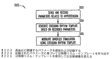
本システムの様々な実施形態が、望ましいレベルの圧反射刺激を適切に印加するために刺激装置1759のモジュレータ1769を制御することが可能な心臓活動モニタ1773、有害事象検出器1774、呼吸モニタ1775、日周期リズムのテンプレート1776のうちのいずれか1つまたはいずれかの組合せを有する。これら1773、1774、1775、1776の各々が圧反射信号を変えるための方法と関連付けられる。様々な実施形態によると、本システムは以下のパラメータまたはパラメータの組合せ、すなわち心臓活動(1773);有害事象(1774);呼吸(1775);日周期リズム(1776);心臓活動(1773)と有害事象(1774);心臓活動(1773)と呼吸(1775);心臓活動(1773)と日周期リズム(1776);有害事象(1774)と呼吸(1775);有害事象(1774)と日周期リズム(1776);呼吸(1775)と日周期リズム(1776);心臓活動(1773)、有害事象(1774)および呼吸(1775);心臓活動(1773)、有害事象(1774)と日周期リズム(1776);心臓活動(1773)、呼吸(1775)と日周期リズム(1776);有害事象(1774)、呼吸(1775)と日周期リズム(1776);心臓活動(1773)、有害事象(1774)、呼吸(1775)、日周期リズム(1776)に基づいて圧反射信号を変えるための手段を有する。様々な実施形態によると、本システムは心拍数をフィードバック・メカニズムとして使用して圧反射刺激を自動的に調節することで望ましい効果を心拍数に与えるための手段を有する。
Various embodiments of the system provide a
刺激は神経幹近傍に位置決めされたカフ電極または血管内供給リード線を使用して迷走神経などの求心性神経幹に印加される。刺激は血管内供給されたリード線を使用して、例えば肺動脈、大動脈弓、頸動脈洞の中に位置する圧受容器部位に印加される。刺激は血管内供給されたリード線を使用して、または電極を脂肪体の中に捻り入れることによって心臓脂肪体の中に位置する圧受容器部位に印加されてもよい。心臓活動検出器1774の実施形態は、例えば、心拍数モニタ1777、毎分換気量モニタ1778、加速度モニタ1779のうちのいずれか1つまたはいずれかの組合せを含む。呼吸モニタ1775は血圧をモニタするための代理として機能する。呼吸モニタ1775の実施形態は1回換気量モニタ1780と毎分換気量モジュールのうちのいずれか1つまたはいずれかの組合せを含む。日周期リズム・テンプレート1776の実施形態は特別注文で作られたテンプレート1782と予めプログラムされたテンプレート1783のうちのいずれか1つまたはいずれかの組合せを含む。これらの実施形態は図18A〜18C、19A〜19B、20A〜20B、21A〜21E、22、23A〜23Cに関連して下記でさらに詳しく考察される。
Stimulation is applied to an afferent nerve trunk such as the vagus nerve using a cuff electrode or an intravascular supply lead positioned near the nerve trunk. Stimulation is applied to baroreceptor sites located, for example, in the pulmonary artery, aortic arch, or carotid sinus using intravascularly supplied leads. Stimulation may be applied to baroreceptor sites located in the cardiac fat pad using intravascularly supplied leads or by twisting electrodes into the fat pad. Embodiments of the
AHT治療を実施するため様々な実施形態が日周期リズム・テンプレートを使用する。無呼吸治療を実施するために様々な実施形態が日周期リズム・テンプレートを使用する。 Various embodiments use a circadian rhythm template to perform AHT therapy. Various embodiments use a circadian rhythm template to perform apnea therapy.
(心臓収縮の間隔に基づいた圧反射刺激の変更)
交感または副交感神経系の活性化は、特定の心臓収縮間隔や、主として駆出前の期間(PEP)、心室内で感知される電気的活性(例えば「R」波の感知)の間の時間的間隔、血液の心室駆出の開始を変化させることが知られている。PEPは肺動脈圧センサを使用して、感知された電気的事象から肺動脈内の圧力上昇の開始までを測定することが可能であり、または駆出時の心室容積の減少に付随する心臓内インピーダンスの増加の開始までを、右心室の中または左心室に及んで配置された電極を使用して測定することが可能である。例えば心拍数または加速度計で測定される身体活動によって判定される休息時では、神経刺激を、予めプログラムされた範囲にPEPを維持するように変える。PEPの突然の減少は運動または情緒的ストレスに付随する交感神経系の緊張の高まりを示す。この状態は、神経刺激を減らして代謝要求に合致するのに必要な心拍数を増加させ、収縮性を増加させるのに使用される。同様の様式で、引き続いて生じるPEPの劇的な延長は増大した代謝要求の終了を特徴付ける。この時に、神経刺激による血圧の制御が再開される。
(Change of baroreflex stimulation based on interval between heart contractions)
The activation of the sympathetic or parasympathetic nervous system depends on the time interval between a specific cardiac contraction interval, mainly the pre-ejection period (PEP), or electrical activity sensed in the ventricle (eg, sensing of “R” waves). It is known to change the onset of blood ventricular ejection. PEP can use a pulmonary artery pressure sensor to measure from a sensed electrical event to the onset of pressure rise in the pulmonary artery, or the intracardiac impedance associated with a decrease in ventricular volume upon ejection. Up to the onset of increase can be measured using electrodes placed in the right ventricle or spanning the left ventricle. At rest, as determined, for example, by physical activity measured with a heart rate or accelerometer, the neural stimulation is changed to maintain the PEP in a preprogrammed range. A sudden decrease in PEP indicates an increase in sympathetic tone associated with exercise or emotional stress. This condition is used to reduce neural stimulation and increase the heart rate required to meet metabolic demand and increase contractility. In a similar manner, the subsequent dramatic extension of PEP characterizes the termination of increased metabolic demand. At this time, control of blood pressure by nerve stimulation is resumed.
(心臓活動に基づいた圧反射刺激の変更)
本主題事項は、例えば心拍数、毎分換気量、加速度、これらの組合せによって判定されるような心臓活動に基づいて圧受容器刺激を自動的に変える方法を記述する。圧受容器を電気的に刺激するためのデバイスの機能性は、代謝要求が相対的に低い休息時に少なくとも相対的に高いボロペーシング速度を加え、代謝要求が増大する身体運動時に徐々に低いボロペーシングを加えることによって強化される。心臓活動の指標は圧受容器の電気刺激を自動的に変えるために使用され、埋込可能な抗高血圧デバイスが代謝要求の変化に応答することを可能にする。様々な実施形態によると、ペースメーカ、AICDまたはCRTデバイスなどのCRMデバイスは圧受容器刺激用リード線も同様に備えている。このデバイスは、例えば混成センサを使用する既存の方法を通じて心臓活動をモニタする。混成センサは加速度や毎分換気量などのパラメータを測定するために2つのセンサを含む。混成センサの出力は複合パラメータを表す。様々なNSとAHT療法はこの開示の中で考察されるように2つ以上の感知されたパラメータから派生する複合パラメータを使用する。休息時(低い心臓活動)では、このデバイスは高速で圧受容器を刺激し、血圧を下げて高血圧を制御する。心臓活動が上昇すると、このデバイスは一時的に圧受容器刺激を減少させることによって応答する。これは結果として血圧と心拍出量の一時的な上昇につながり、身体を増大した代謝要求に応答できるようにする。例えば、いくつかの実施形態は休息時に圧反射刺激を供給し、運動時に圧反射刺激を引き下げて運動に対応した通常の血圧に一致させる。活動を判定するために圧力トランスデューサを使用することが可能である。さらに、心拍感応型ぺーシングを推進するために使用され、または使用されてきたセンサを使用して活動を感知することも可能である。そのようなセンサの例は身体の動き、心拍数、QT間隔、呼吸速度、経胸腔インピーダンス、1回換気量、毎分換気量、身体姿勢、脳波図(EEG)、心電図(ECG)、眼電図(EOG)、筋電図(EMG)、筋緊張、体温、脈波型酸素飽和度測定、時刻、(心臓内インピーダンスから)駆出前間隔を検出するためのセンサを含む。
(Change of baroreflex stimulation based on heart activity)
The present subject matter describes a method for automatically changing baroreceptor stimulation based on cardiac activity as determined, for example, by heart rate, minute ventilation, acceleration, and combinations thereof. The functionality of the device to electrically stimulate baroreceptors adds at least a relatively high boropacing rate at rest when the metabolic demand is relatively low, and gradually lower boropacing during physical exercise with increased metabolic demand. Strengthened by adding. Cardiac activity indicators are used to automatically alter baroreceptor electrical stimulation, allowing implantable antihypertensive devices to respond to changes in metabolic demand. According to various embodiments, a CRM device, such as a pacemaker, AICD or CRT device, also includes baroreceptor stimulation leads. This device monitors cardiac activity through existing methods, for example using hybrid sensors. Hybrid sensors include two sensors to measure parameters such as acceleration and minute ventilation. The output of the hybrid sensor represents a composite parameter. Various NS and AHT therapies use composite parameters derived from two or more sensed parameters as discussed in this disclosure. At rest (low cardiac activity), the device stimulates baroreceptors at high speed, lowering blood pressure and controlling hypertension. As cardiac activity increases, the device responds by temporarily reducing baroreceptor stimulation. This results in a temporary increase in blood pressure and cardiac output, allowing the body to respond to increased metabolic demands. For example, some embodiments provide baroreflex stimulation at rest and lower baroreflex stimulation during exercise to match normal blood pressure corresponding to the exercise. A pressure transducer can be used to determine activity. Furthermore, it is possible to sense activity using sensors that have been or have been used to promote heart rate sensitive pacing. Examples of such sensors are body movement, heart rate, QT interval, respiratory rate, transthoracic impedance, tidal volume, tidal volume, body posture, electroencephalogram (EEG), electrocardiogram (ECG), electrooculogram. Includes sensors to detect figure (EOG), electromyogram (EMG), muscle tone, body temperature, pulse wave oxygen saturation measurement, time of day, and pre-ejection interval (from intracardiac impedance).
心臓活動モニタの様々な実施形態が、平均動脈圧、心臓収縮圧と心臓拡張圧の間の差異によって決定される脈圧、終末収縮圧(心臓収縮終末の圧力)、終末拡張圧(心臓拡張終末の圧力)などの少なくとも1つの圧力パラメータを検出するためのセンサを含む。心臓活動モニタの様々な実施形態が1回拍出量モニタを含む。1回拍出量を導き出すために心拍数と圧力を使用することが可能である。心臓活動モニタの様々な実施形態が、心臓の活動を判定するための少なくとも1つの電気記録図測定を使用する。そのような電気記録図測定の例はR−R間隔、P−R間隔、QT間隔を含む。心臓活動モニタの様々な実施形態が、心臓の活動を判定するための少なくとも1つの心電図(ECG)測定を使用する。 Various embodiments of the cardiac activity monitor include mean arterial pressure, pulse pressure determined by the difference between systolic pressure and diastole pressure, end systolic pressure (end systolic pressure), end diastole pressure (end diastole) A sensor for detecting at least one pressure parameter, such as Various embodiments of the cardiac activity monitor include a stroke volume monitor. Heart rate and pressure can be used to derive stroke volume. Various embodiments of the cardiac activity monitor use at least one electrogram measurement to determine cardiac activity. Examples of such electrogram measurements include RR intervals, PR intervals, and QT intervals. Various embodiments of the cardiac activity monitor use at least one electrocardiogram (ECG) measurement to determine cardiac activity.
図18A〜18Cは心臓活動パラメータに基づいて圧受容器刺激を変えるための、本主題事項の様々な実施形態による方法を示している。心臓活動はCRMデバイス、NSデバイス、またはNS/CRM能力を備えた埋込可能なデバイスによって判定される。心臓活動に基づいて圧受容器刺激を変えるための第1の処理1884Aが図18Aに図示されている。1885Aで活動レベルが判定される。様々な実施形態によると、活動レベルの判定は心拍数、毎分換気量、加速度、または心拍数、毎分換気量、加速度のいずれかの組合せに基づいている。図示された処理では、活動レベルは2つの規定された2進レベル(例えばHIとLO)を有する。いくつかの実施形態では、LOレベルは無刺激を含む。活動レベルがHIであるかまたはLOであるかが判定される。1886Aでは、判定された活動レベルに基づいて圧受容器刺激レベルが設定される。活動レベルがHIであると判定されればLO刺激レベルが設定され、活動レベルがLOであると判定されればHI刺激レベルが設定される。 18A-18C illustrate methods according to various embodiments of the present subject matter for varying baroreceptor stimulation based on cardiac activity parameters. Cardiac activity is determined by a CRM device, NS device, or an implantable device with NS / CRM capabilities. A first process 1884A for changing baroreceptor stimulation based on cardiac activity is illustrated in FIG. 18A. The activity level is determined at 1885A. According to various embodiments, the activity level determination is based on heart rate, minute ventilation, acceleration, or any combination of heart rate, minute ventilation, acceleration. In the illustrated process, the activity level has two defined binary levels (eg, HI and LO). In some embodiments, the LO level includes no stimulation. It is determined whether the activity level is HI or LO. At 1886A, a baroreceptor stimulation level is set based on the determined activity level. If it is determined that the activity level is HI, the LO stimulation level is set, and if the activity level is determined to be LO, the HI stimulation level is set.
心臓活動に基づいて圧受容器刺激を変えるための第2の処理1884Bが図18Bに図示されている。1885Bで活動レベルが判定される。様々な実施形態によると、活動レベルの判定は心拍数、毎分換気量、加速度、または心拍数、毎分換気量、加速度のいずれかの組合せに基づいている。図示された処理では、活動レベルは2つを超える規定レベルまたはn個の規定レベルを有する。活動レベルがレベル1、レベル2、...レベルnのいずれであるかが判定される。活動レベルの標示は増大する活動に相当する。1886Bでは、判定された活動レベルに基づいて圧受容器刺激レベルが設定される。利用可能な刺激レベルはレベルn、...レベル2、レベル1を含み、刺激レベルの標示は増大する刺激に相当する。様々な実施形態によると、選択される圧受容器刺激レベルは判定された活動レベルと逆の関係にされる。例えば、心臓活動レベルが最高レベルnにあると判定されれば、刺激レベルは最低レベルnに設定される。刺激レベルが最低レベルに対して1番目または2番目のそれぞれレベル1またはレベル2にあると判定されれば、刺激レベルは最高レベルに対して1番目または2番目のそれぞれレベル1またはレベル2に設定される。
A
心臓活動に基づいて圧受容器刺激を変えるための別の処理1884Cが図18Cに示されている。1887で、入手された心臓活動パラメータが目標の活動パラメータと比較される。入手された心臓活動パラメータが目標の活動パラメータよりも低ければ1888で圧受容器刺激が上げられる。入手された心臓活動パラメータが目標の活動パラメータよりも高ければ1889で圧受容器刺激が下げられる。図26A、26Bに関して下記で考察されるように、心拍数または他のモニタされた心臓血管パラメータまたは心拍数に伴って増加し、減少する心拍数の代理パラメータへの所望の効果を達成するために様々な実施形態は圧受容器刺激を変更または変化させる。例えば、様々な実施形態が刺激時の目標の心拍数を無刺激時の心拍数よりも下のパーセンテージ(例えば5%、10%など)であるように設定し、様々な実施形態が刺激時の目標の心臓を無刺激時の心拍数よりも下の定量値(例えば5bpm、10bpmなど)であるように設定する。そのようなシステムは、神経系の刺激への適応化、刺激装置に付随する電気的インピーダンスまたは他のデバイス特性、組織の被包および線維形成などの系の変化に関係なく望ましい刺激レベルを供給し続ける。
Another
本主題事項の態様は、1回換気量または毎分換気量で判定される呼吸に基づいて圧受容器刺激の強度を自動的に変えるための方法に関する。連続して圧受容器刺激を加えるのではなく、血圧の代理として呼吸を使用してNSデバイスが高血圧のレベルをモニタして適切な治療のレベルを供給し、デバイスが治療のレベルを変えることを可能にする。本主題事項は1回換気量と毎分換気量を判定するため、および圧受容器刺激を自動的に変えるために例えばインピーダンスなどの呼吸の指標を使用する。したがって、埋込可能なNSデバイスは患者の高血圧のレベルを判定することが可能であり、適切な治療のレベルを供給することによって対応する。様々な実施形態で、埋込可能なNSデバイスは1回換気量または毎分換気量を測定するためのセンサを有する。例えば、様々な実施形態は呼吸の速度を入手するために経胸腔インピーダンスを測定する。いくつかの実施形態ではこのデバイスはCRMデバイスからこのデータを受け取る。NSデバイスはこれらの呼吸パラメータを周期的にモニタする。呼吸がプログラム可能な目標よりも下に減少または留まると、このデバイスが増大した速度で圧受容器を刺激し、血圧を下げて高血圧を制御する。平均動脈圧が目標に向かって増大すると、このデバイスは圧受容器刺激を減少させることによって対応する。この方式で、AHTデバイスは適切な治療のレベルを連続して供給する。 Aspects of the present subject matter relate to a method for automatically changing the intensity of baroreceptor stimulation based on respiration determined at tidal volume or minute ventilation. Rather than continuously applying baroreceptor stimulation, using NS as a surrogate for blood pressure, the NS device can monitor the level of hypertension and provide the appropriate level of therapy, allowing the device to change the level of therapy To. The present subject matter uses respiratory indicators such as impedance to determine tidal and minute ventilation and to automatically change baroreceptor stimulation. Thus, the implantable NS device can determine the patient's level of hypertension and responds by providing an appropriate level of treatment. In various embodiments, the implantable NS device has a sensor for measuring tidal volume or minute ventilation. For example, various embodiments measure transthoracic impedance to obtain the rate of respiration. In some embodiments, the device receives this data from the CRM device. NS devices periodically monitor these respiratory parameters. When breathing decreases or stays below a programmable target, the device stimulates baroreceptors at an increased rate and lowers blood pressure to control hypertension. As the mean arterial pressure increases toward the target, the device responds by reducing baroreceptor stimulation. In this manner, the AHT device continuously delivers the appropriate level of treatment.
図19A〜19Bは呼吸パラメータに基づいて圧受容器刺激を変えるための、本主題事項の様々な実施形態による方法を図示している。呼吸パラメータはCRMデバイス、NSデバイス、またはNS/CRM能力を備えた埋込可能なデバイスによって判定される。呼吸パラメータに基づいて圧受容器刺激を変えるための方法の一実施形態が図19Aの1910Aで示されている。1911で呼吸レベルが判定され、判定された呼吸レベルに基づいて1912で圧受容器刺激レベルが設定される。様々な実施形態によると、望ましいボロペーシングのレベルが1913で調整される。例えば、一実施形態は得られたパラメータを1914で目標のパラメータと比較する。得られたパラメータと目標のパラメータの比較に基づいてボロペーシングが1915で上げられ、1916で下げられる。 19A-19B illustrate methods according to various embodiments of the present subject matter for varying baroreceptor stimulation based on respiratory parameters. Respiratory parameters are determined by CRM devices, NS devices, or implantable devices with NS / CRM capabilities. One embodiment of a method for varying baroreceptor stimulation based on respiratory parameters is shown at 1910A in FIG. 19A. A respiratory level is determined at 1911 and a baroreceptor stimulation level is set at 1912 based on the determined respiratory level. According to various embodiments, the desired level of boropacing is adjusted at 1913. For example, one embodiment compares the obtained parameter to the target parameter at 1914. Based on the comparison between the obtained parameter and the target parameter, boropacing is increased at 1915 and decreased at 1916.
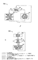
呼吸パラメータに基づいて圧受容器刺激を変えるための方法の一実施形態が図19Bの1910Bで図示されている。1916で、圧反射事象のトリガが生じ、これが圧反射刺激処理に関するアルゴリズムを始動させる。1917で、呼吸が目標のパラメータと比較される。呼吸が目標よりも下であれば、1918で、圧反射刺激が増大させられ、呼吸が目標よりも上であれば、1919で、圧反射刺激が減少させられる。様々な実施形態によると、呼吸が空白化ウィンドウの中に落ちれば刺激は変更されない。様々な実施形態が、印加される刺激と圧反射応答を安定にするようにヒステリシス効果を供給するためにメモリを使用する。さらに、様々な実施形態で、呼吸の目標値は時刻または活動レベルなどの様々な因子に基づいて治療中に変更される。1920で、例えば感知されたパラメータまたは事象中断の受信に基づいて圧反射療法アルゴリズムを続けるかどうかが判定される。圧反射アルゴリズムが継続する場合、処理は1917に戻り、ここで呼吸が再び目標のパラメータと比較され、その他の場合、1921で圧反射アルゴリズムは中止される。 One embodiment of a method for changing baroreceptor stimulation based on respiratory parameters is illustrated at 1910B in FIG. 19B. At 1916, a baroreflex event trigger occurs, which triggers an algorithm for baroreflex stimulation processing. At 1917, respiration is compared to target parameters. If respiration is below the target, the baroreflex stimulation is increased at 1918, and if respiration is above the target, the baroreflex stimulation is decreased at 1919. According to various embodiments, the stimulus is not changed if the breath falls into the blanking window. Various embodiments use memory to provide a hysteresis effect to stabilize the applied stimulus and baroreflex response. Further, in various embodiments, the target breathing value is changed during treatment based on various factors such as time of day or activity level. At 1920, it is determined whether to continue the baroreflex therapy algorithm based on, for example, receiving a sensed parameter or event interruption. If the baroreflex algorithm continues, processing returns to 1917 where breathing is again compared to the target parameter; otherwise, at 1921 the baroreflex algorithm is aborted.
(有害事象に基づいた圧反射刺激の変更)
本主題事項の態様は、血管拡張応答を増大させるため、および心筋虚血損傷を潜在的に阻止するためまたは減少させるために有害な心臓の事象を検出すると圧受容器刺激を自動的に増大させる方法を含む。様々な実施形態が、心臓律動管理デバイス(例えばペースメーカ、AICDまたはCRTデバイスなど)内にフィードバック・メカニズムを有し、そのデバイスも同様に圧受容器を電気的に刺激するための刺激用リード線を有する。このデバイスは既にある方法を通じて心臓の電気的活動をモニタする。心室細動(VF)と心房細動(AF)、予め規定された速度を上回る心室頻脈(VT)と心房頻脈(AT)、さらには毎分換気量センサによって検出される呼吸困難、狭心症、代償不全、虚血などの有害な心臓事象の事象で、このデバイスは圧受容器刺激を最大許容レベルまで上げることによって対応する。結果として、血圧が一時的に下げられ、虚血に起因する心筋の損傷を潜在的に阻止するかまたは減少させる。圧受容器刺激の量を一時的に変えることによって有害な心臓事象に対応することが可能であれば、高血圧を治療するデバイスの機能性を広げることが可能である。事象検出アルゴリズムが圧受容器刺激を自動的に変え、埋込可能なAHTデバイスが圧受容器刺激を増大させることによって有害事象に対応することを可能にし、心筋の虚血損傷を潜在的に阻止するかまたは減少させる。
(Change of baroreflex stimulation based on adverse events)
An aspect of the present subject matter is a method for automatically increasing baroreceptor stimulation upon detecting a detrimental cardiac event to increase the vasodilator response and to potentially prevent or reduce myocardial ischemic damage including. Various embodiments have a feedback mechanism in a cardiac rhythm management device (such as a pacemaker, AICD or CRT device) that also has a stimulation lead to electrically stimulate baroreceptors . This device monitors the electrical activity of the heart through existing methods. Ventricular fibrillation (VF) and atrial fibrillation (AF), ventricular tachycardia (VT) and atrial tachycardia (AT) exceeding pre-determined speeds, dyspnea detected by minute ventilation sensor, narrow In the event of adverse cardiac events such as heart disease, decompensation, ischemia, the device responds by raising baroreceptor stimulation to the maximum acceptable level. As a result, blood pressure is temporarily lowered, potentially preventing or reducing myocardial damage resulting from ischemia. If it is possible to respond to adverse cardiac events by temporarily changing the amount of baroreceptor stimulation, the functionality of a device for treating hypertension can be extended. Whether the event detection algorithm automatically changes baroreceptor stimulation, allowing an implantable AHT device to respond to adverse events by increasing baroreceptor stimulation and potentially preventing myocardial ischemic damage Or reduce.
図20A〜20Bは有害事象の検出に基づいて圧受容器刺激を変えるための、本主題事項の様々な実施形態による方法を示している。有害事象はCRMデバイス、NSデバイス、またはNS/CRM能力を備えた埋込可能なデバイスによって判定される。図20Aは有害事象の検出に基づいて圧受容器刺激を変えるための一実施形態を示している。2090Aで、有害事象が検出されたかどうかが判定される。有害事象が検出されなかった場合、2091Aで通常のボロペーシング(標準的手順によるボロペーシング)が行われる。有害事象が検出された場合、2092で強化されたボロペーシングが実行される。様々な実施形態で、有害事象が検出されると最大許容ボロペーシングが実行される。他のボロペーシングが実施されることも可能である。例えば、様々な実施形態が通常ではボロペーシング刺激を加えて有害事象が検出されるとボロペーシング療法を差し控え、また、他の様々な実施形態が通常ではボロペーシング療法を差し控えて有害事象が検出されるとボロペーシング刺激を加える。図20Bは有害事象の検出に基づいて圧受容器刺激を変えるための実施形態を図示している。2090Bで、有害事象が検出されたかどうかが判定される。有害事象が検出されなかった場合、2091Bで通常のボロペーシング(標準的手順によるボロペーシング)が実行される。有害事象が検出された場合、この事象が2093で識別され、識別された有害事象に関して適切なボロペーシングが2094で加えられる。例えば、適切な血圧治療は心室細動と虚血とで異なる可能性が高い。様々な実施形態によると、望ましいボロペーシングが2095で識別された事象に対して調整される。例えば、一実施形態は得られたパラメータを2096で目標のパラメータと比較する。得られたパラメータと目標のパラメータの比較に基づいてボロペーシングが2097で上げられ、2098で下げられる。 20A-20B illustrate methods according to various embodiments of the present subject matter for altering baroreceptor stimulation based on detection of an adverse event. Adverse events are determined by CRM devices, NS devices, or implantable devices with NS / CRM capabilities. FIG. 20A illustrates one embodiment for changing baroreceptor stimulation based on detection of an adverse event. At 2090A, it is determined whether an adverse event has been detected. If no adverse event is detected, normal boropacing (bolocaping according to standard procedures) is performed at 2091A. If an adverse event is detected, boropacing enhanced at 2092 is performed. In various embodiments, maximum allowable boropacing is performed when an adverse event is detected. Other boropacing can be performed. For example, various embodiments typically refrain from boropacing therapy when a boropacing stimulus is applied and an adverse event is detected, and other various embodiments typically refrain from boropacing therapy and detect an adverse event. Then add a boropacing stimulus. FIG. 20B illustrates an embodiment for changing baroreceptor stimulation based on the detection of an adverse event. At 2090B, it is determined whether an adverse event has been detected. If no adverse event is detected, normal boropacing (standard procedure boropacing) is performed at 2091B. If an adverse event is detected, this event is identified at 2093 and appropriate boropacing is added at 2094 for the identified adverse event. For example, appropriate blood pressure treatment is likely to differ between ventricular fibrillation and ischemia. According to various embodiments, the desired boropacing is adjusted for events identified at 2095. For example, one embodiment compares the obtained parameter to the target parameter at 2096. Based on the comparison of the obtained parameter to the target parameter, boropacing is increased at 2097 and decreased at 2098.
様々な実施形態によると、有害事象は心不整脈を防止するための治療を加えることが可能となるような検出可能な予兆を有する。いくつかの実施形態で、有害事象は心臓事象と発作などの非心臓事象の両方を含む。さらに、いくつかの実施形態は不整脈と非不整脈事象の両方を有害事象として識別する。 According to various embodiments, an adverse event has a detectable symptom such that treatment can be added to prevent cardiac arrhythmia. In some embodiments, adverse events include both cardiac events and non-cardiac events such as stroke. Further, some embodiments identify both arrhythmia and nonarrhythmic events as adverse events.
(日周期リズムに基づいた圧反射刺激の変更)
本主題事項の態様は、24時間にわたって起こる血圧の自然な変動を模倣するように高血圧患者で圧反射を刺激するための方法に関する。高血圧における反射の減少は動脈圧の内因性変動を変えることなく長期間の圧受容器刺激の中で達成される。様々な実施形態によると、例えば埋込可能なデバイスは頸動脈洞、肺動脈、または大動脈弓内で高周波数のバースト(例えば約20〜150Hzの範囲内の周波数を備えた矩形波)を使用して圧受容器を刺激するように設計される。いくつかの実施形態は頸動脈洞神経、大動脈神経、または迷走神経をカフ電極で直接刺激する。しかしながら、バーストは一定の速度で起こらない。どちらかといえば刺激の周波数、振幅、および/またはバースト周波数は1日の中で自然の日周期リズムを模倣して上下する。
(Change of baroreflex stimulation based on circadian rhythm)
An aspect of the present subject matter relates to a method for stimulating a baroreflex in a hypertensive patient so as to mimic the natural variation in blood pressure that occurs over a 24 hour period. Reduction of reflexes in hypertension is achieved during long-term baroreceptor stimulation without changing the intrinsic variation of arterial pressure. According to various embodiments, for example, the implantable device uses a high frequency burst (eg, a square wave with a frequency in the range of about 20-150 Hz) within the carotid sinus, pulmonary artery, or aortic arch. Designed to stimulate baroreceptors. Some embodiments stimulate the carotid sinus nerve, aortic nerve, or vagus nerve directly with a cuff electrode. However, bursts do not occur at a constant rate. If anything, the frequency, amplitude, and / or burst frequency of the stimulus goes up and down in the day, mimicking the natural circadian rhythm.
したがって、NSデバイスの様々な実施形態は正常な個人と高血圧の個人の両方で起こる動脈圧の自然な変動を考慮する。活動に関連する平均動脈圧の変化に加えて、主題は24時間サイクルの一貫した圧力の変動を示す。周期的な圧受容器刺激を供給するデバイスが本来の日周期リズムを模倣し、このリズムを妨げることなく系統的神経系の反射阻害と低下した全身血圧を可能にする。本主題事項は、本来の日周期リズムを妨げることなく平均動脈圧を下げるために圧受容器刺激の周波数/振幅を変えるペーシングプロトコルを提供する。 Thus, various embodiments of NS devices take into account the natural fluctuations in arterial pressure that occur in both normal and hypertensive individuals. In addition to the change in mean arterial pressure associated with activity, the subject shows a consistent pressure variation over a 24-hour cycle. A device that provides periodic baroreceptor stimulation mimics the natural circadian rhythm, allowing systemic nervous system reflex inhibition and reduced systemic blood pressure without interfering with this rhythm. The present subject matter provides a pacing protocol that varies the frequency / amplitude of baroreceptor stimulation to reduce mean arterial pressure without disturbing the original circadian rhythm.
図21A〜21Eは日周期リズムを図示している。図21Aは正午から正午までの24時間について平均動脈圧に関連する日周期リズムを示しており、図21Bは正午から正午までの24時間について心拍数に関連する日周期リズムを示しており、図21Cは正午から正午までの24時間について1回拍出量のパーセント変化(SV%)に関連する日周期リズムを示しており、図21Dは正午から正午までの24時間について心拍出量(CO)のパーセント変化に関連する日周期リズムを示しており、図21Eは正午から正午までの24時間について血管拡張の指標である全末梢血管抵抗のパーセント変化(TPR%)に関連する日周期リズムを示している。様々な実施形態が絶対値をグラフに描き、様々な実施形態がパーセント値をグラフにしている。これらの図で、点線で囲った部分は午後10時頃から午前7時までの夜の時間を表し、したがって休息または睡眠時間を表す。例えば図21A、21Bを参照すると、平均動脈圧と心拍数の両方が休息の期間中に下がることが明らかである。高い血圧と心拍数は休息に悪影響を与える可能性が高い。さらに、1日中の低い血圧と心拍数は個人のエネルギーのレベルに悪影響を与える可能性が高い。 21A-21E illustrate the circadian rhythm. FIG. 21A shows the circadian rhythm related to mean arterial pressure for 24 hours from noon to noon, and FIG. 21B shows the circadian rhythm related to heart rate for 24 hours from noon to noon. 21C shows the circadian rhythm associated with the percent change in stroke volume (SV%) for 24 hours from noon to noon, and FIG. 21D shows the cardiac output (CO) for 24 hours from noon to noon. ) Shows the circadian rhythm associated with the percent change in total peripheral vascular resistance (TPR%), which is an indicator of vasodilation for 24 hours from noon to noon. Show. Various embodiments graph absolute values, and various embodiments graph percentage values. In these figures, the portion surrounded by a dotted line represents the night time from about 10 pm to 7 am, and thus represents rest or sleep time. For example, referring to FIGS. 21A and 21B, it is apparent that both mean arterial pressure and heart rate decrease during the rest period. High blood pressure and heart rate are likely to adversely affect rest. In addition, low blood pressure and heart rate throughout the day are likely to adversely affect an individual's energy level.
本主題事項の様々な実施形態が、多くの被験者について日周期リズムと一致するように意図された予めプログラムされたテンプレートを使用して圧反射刺激を変えるようになっている。本主題事項の様々な実施形態が被験者に一致するように特別に誂えられたテンプレートを生成する。 Various embodiments of the present subject matter are adapted to alter baroreflex stimulation using a pre-programmed template that is intended to match the circadian rhythm for many subjects. Various templates of the present subject matter are generated that are specifically tailored to match the subject.
図22は特別に誂えられた日周期リズムのテンプレートを使用して日周期リズムに基づいて圧受容器刺激を変えるための、本主題事項の様々な実施形態による方法を図示している。図示された方法2222は2223で、高血圧に関連するパラメータ群を感知し、記録する。そのようなパラメータの例は心拍数と平均動脈圧を含む。2224で、これらの記録されたパラメータに基づいて日周期リズムのテンプレートを生成する。2225で、圧反射刺激が2224で生成された日周期リズムのテンプレートを使用して変えられる。
FIG. 22 illustrates a method according to various embodiments of the present subject matter for changing baroreceptor stimulation based on a circadian rhythm using a specially tailored circadian rhythm template. The illustrated
(望ましい心拍出量を供給するための圧反射刺激の変更)
本主題事項の態様は、圧反射を刺激することによって全身血圧を下げるためのNS療法を実施し、速度制御のための心臓ペーシング用リード線を使用して心臓ペーシング療法をさらに実施する埋込可能な医学デバイスに関する。圧反射刺激と心臓ペーシングは連携して起こり、心拍出量を犠牲にせずに血圧を下げることができる。
(Modification of baroreflex stimulation to provide desired cardiac output)
An aspect of the present subject matter implements NS therapy to lower systemic blood pressure by stimulating baroreflex and further implements cardiac pacing therapy using cardiac pacing leads for rate control Related to medical devices. Baroreflex stimulation and cardiac pacing work in tandem and can lower blood pressure without sacrificing cardiac output.
様々な実施形態によると、圧反射刺激装置は別の埋込可能なCRMデバイスと通信し、既存のペーシング用リード線を使用する。様々な実施形態で、圧反射刺激は、血管壁の中または隣接して配置された電極を備えた肺動脈、頸動脈洞、または大動脈弓内の圧受容器を通じて起こる。様々な実施形態で、大動脈神経、頸動脈洞神経、または迷走神経などの求心性神経がカフ電極で直接刺激される。 According to various embodiments, the baroreflex stimulator communicates with another implantable CRM device and uses existing pacing leads. In various embodiments, baroreflex stimulation occurs through baroreceptors in the pulmonary artery, carotid sinus, or aortic arch with electrodes placed in or adjacent to the vessel wall. In various embodiments, afferent nerves such as the aortic nerve, carotid sinus nerve, or vagus nerve are stimulated directly with a cuff electrode.
圧反射刺激は結果として迅速に血管拡張につながり、全身血圧を下げる。同時に起こる心拍出量の低下を補償するために、圧反射刺激中のペーシング速度が上げられる。本主題事項は、圧反射刺激と心臓ペーシングを組み合わせることによって圧反射刺激を通じて血圧を徐々に下げ、その一方で心拍出量の低下(そうしない場合にそのような刺激に随伴する)を回避し、埋込可能なデバイスが血圧制御中の心拍出量を維持する。 Baroreflex stimulation results in rapid vasodilation and lowers systemic blood pressure. To compensate for the concomitant decline in cardiac output, the pacing rate during baroreflex stimulation is increased. This subject matter gradually reduces blood pressure through baroreflex stimulation by combining baroreflex stimulation with cardiac pacing, while avoiding lowering cardiac output (which otherwise accompanies such stimulation). An implantable device maintains cardiac output during blood pressure control.
図23A〜Bは心拍出量パラメータに基づいて圧受容器刺激を変えるための、本主題事項の様々な実施形態による方法を示している。図23Aは心拍出量パラメータに基づいて圧受容器刺激を変えるための一実施形態を示している。図示された処理2326Aでは、圧反射刺激が2327で加えられているかどうかが判定される。圧反射刺激が加えられていなければ、本主題事項は2328で(あるとすれば)適切なペーシング療法を適切なペーシング速度で実施する。圧反射刺激が加えられていなければ、本主題事項は心拍出量を維持するために2329でさらに高いペーシング速度でペーシング療法を実施する。
FIGS. 23A-B illustrate methods according to various embodiments of the present subject matter for varying baroreceptor stimulation based on cardiac output parameters. FIG. 23A illustrates one embodiment for varying baroreceptor stimulation based on cardiac output parameters. In the illustrated
図23Bは心拍出量パラメータに基づいて圧受容器刺激を変えるための一実施形態を示している。図示された処理2326Bでは、圧反射刺激が2330で加えられ、心拍出量が適切であるかどうかが2331で判定される。心拍出量が適切でないと判定すると、適切な心拍出量を維持するために2332でペーシング速度が上げられる。
FIG. 23B illustrates one embodiment for varying baroreceptor stimulation based on cardiac output parameters. In the illustrated
様々な実施形態によると、現行のペーシング速度は心拍出量を維持するために圧反射刺激の間では所定のファクタで上げられる。様々な実施形態によると、ペーシング速度は心拍出量を維持するために圧反射刺激の間に開始される。望ましい心拍出量を供給するための圧反射刺激の変更は心房と心室の速度制御、AV遅延制御、再同期、多点刺激で実施される。別法として、右心室空洞の中の電極を使用して右心室のインピーダンスによって、または左心室空洞の中またはその空洞に広がる電極を使用して左心室のインピーダンスによって1回拍出量がモニタされ、一定の心拍出量を維持するためにペーシング速度が神経刺激の活用を使用して上げられる。 According to various embodiments, the current pacing rate is increased by a predetermined factor during baroreflex stimulation to maintain cardiac output. According to various embodiments, the pacing rate is initiated during baroreflex stimulation to maintain cardiac output. Altering baroreflex stimulation to provide the desired cardiac output is performed with atrial and ventricular velocity control, AV delay control, resynchronization, and multipoint stimulation. Alternatively, stroke volume is monitored by the right ventricular impedance using an electrode in the right ventricular cavity or by the left ventricular impedance using an electrode in or extending into the left ventricular cavity. To maintain a constant cardiac output, the pacing rate is increased using the use of neural stimulation.
(硬化過程をリモデルするための圧反射刺激の変更)
本主題事項の態様は、難治性の高血圧を持つ患者の全身血圧を下げるために埋込可能なNSデバイスによって使用される圧反射刺激のための方法を含む。プログラム可能な目標に向けて血圧を緩やかに調節するために圧反射刺激アルゴリズムが圧反射刺激を徐々に高める。このアルゴリズムは中枢神経系が圧反射刺激の定常的高レベルに順応する(これは通常、降圧効果を弱める)のを阻止する。さらに、血圧変化の漸進性質は全身血圧と心拍出量の急激な変化を伴なわずに患者はさらに良好に療法に耐えることができる。
(Change of baroreflex stimulation to remodel the curing process)
Aspects of the present subject matter include a method for baroreflex stimulation used by an implantable NS device to lower systemic blood pressure in patients with refractory hypertension. The baroreflex stimulation algorithm gradually increases the baroreflex stimulation to gently adjust the blood pressure toward a programmable target. This algorithm prevents the central nervous system from adapting to a steady high level of baroreflex stimulation (which usually diminishes the antihypertensive effect). Furthermore, the progressive nature of blood pressure changes allows patients to better tolerate therapy without abrupt changes in systemic blood pressure and cardiac output.
本主題事項は、上昇した圧反射刺激への中枢神経系の順応を阻止するため、患者に存在する前の高血圧状態によって誘発される動脈硬化過程を逆戻りさせるように血圧レベルを時間と共に緩やかに下げるため、および圧受容器刺激の間の心拍出量の低下を阻止するために設計された特別のアルゴリズムまたは処理過程を提供する。時間と共に、動脈系は既に存在する高血圧によって始められた硬化過程を逆方向にリモデルすることが予期される。平均/中央値の血圧の緩やかで漸進的な低下は逆方向のリモデリングを通じてこの硬化過程の緩やかな逆戻りを可能にする。心拍出量で譲歩することなく、血圧がこの過程の中で下げられ、したがって望ましくない患者の症状を回避する。 The subject matter slowly reduces blood pressure levels over time to reverse the arteriosclerosis process induced by the previous hypertensive state present in the patient to prevent adaptation of the central nervous system to elevated baroreflex stimulation And a special algorithm or process designed to prevent the reduction in cardiac output during baroreceptor stimulation. Over time, the arterial system is expected to remodel the sclerosis process initiated by preexisting hypertension in the opposite direction. The gradual and gradual decline in mean / median blood pressure allows this gradual reversal of the curing process through reverse remodeling. Without making concessions in cardiac output, blood pressure is lowered during this process, thus avoiding undesirable patient symptoms.
様々な実施形態で、デバイスは肺動脈、頸動脈洞、または大動脈弓内の圧受容器を血管壁の中または隣接して配置された電極で刺激する。様々な実施形態で、大動脈神経、頸動脈洞神経、または迷走神経などの求心性神経がカフ電極で直接刺激される。刺激された圧反射は結果として迅速に血管拡張や全身血圧の低下につながる。しかしながら、定常的に圧反射を上昇したレベルに刺激するのではなく、本主題事項のデバイスは初期には僅かに上昇したレベルで刺激し、次いで例えば数週間または数ヶ月の期間にわたって徐々に刺激を増大させる。変化の速度は現在と目標の動脈圧に基づいてデバイスによって判定される。様々な実施形態で、システムは圧力の減少が低下した心拍出量の犠牲によって起こらないことを確実にするために心拍出量の直接的または間接的測定に基づいて変化の速度を決定する。様々な実施形態で、圧反射刺激の速度は一定ではなく、神経連絡分布をさらに密接に模倣するようにホワイトノイズ型の分布を有する。神経連絡分布を模倣することによって、圧反射が刺激に対してさらに良く反応し、したがって圧反射を刺激するための閾値を下げることが予期される。 In various embodiments, the device stimulates baroreceptors in the pulmonary artery, carotid sinus, or aortic arch with electrodes placed in or adjacent to the vessel wall. In various embodiments, afferent nerves such as the aortic nerve, carotid sinus nerve, or vagus nerve are stimulated directly with a cuff electrode. The stimulated baroreflex results in rapid vasodilation and a decrease in systemic blood pressure. However, instead of constantly stimulating the baroreflex to an elevated level, the device of the present subject matter initially stimulates at a slightly elevated level and then gradually stimulates over a period of, for example, weeks or months. Increase. The rate of change is determined by the device based on the current and target arterial pressure. In various embodiments, the system determines the rate of change based on direct or indirect measurement of cardiac output to ensure that pressure reduction does not occur at the expense of reduced cardiac output. . In various embodiments, the rate of baroreflex stimulation is not constant and has a white noise type distribution to more closely mimic the neural communication distribution. By mimicking the neural communication distribution, it is expected that the baroreflex will respond better to the stimulus and thus lower the threshold for stimulating the baroreflex.
図24は硬化を逆方向にリモデルするように圧受容器刺激を変えるための、本主題事項の様々な実施形態による方法を示している。圧反射事象のトリガが2433で起こる。このトリガは圧反射刺激を開始するどのような事象をも含み、AHTデバイスの活性化を含む。2434で、所定の変化の速度で圧反射刺激を増大させて硬化過程を逆方向にリモデルするように血圧を目標の圧力に徐々に下げるためのアルゴリズムが実行される。2435で、圧反射刺激アルゴリズムを続行するべきかどうかが判定される。例えば事象中断、感知パラメータ、および/または目標血圧の達成に基づいて2436でアルゴリズムが中止される。2437で、心拍出量が受容可能であるかどうかが判定される。心拍出量が受容不可能であれば、2438で圧反射刺激に関する変化の速度は心拍出量に基づいて変更される。 FIG. 24 illustrates a method according to various embodiments of the present subject matter for altering baroreceptor stimulation to remodel the cure in the reverse direction. A baroreflex event trigger occurs at 2433. This trigger includes any event that initiates baroreflex stimulation and includes activation of the AHT device. At 2434, an algorithm is executed to gradually lower the blood pressure to the target pressure so as to increase the baroreflex stimulation at a predetermined rate of change and remodel the curing process in the reverse direction. At 2435, it is determined whether the baroreflex stimulation algorithm should continue. The algorithm is stopped at 2436 based on, for example, event interruption, sensing parameters, and / or achievement of target blood pressure. At 2437, it is determined whether the cardiac output is acceptable. If the cardiac output is unacceptable, at 2438 the rate of change for baroreflex stimulation is changed based on the cardiac output.
(心筋梗塞を治療するための圧反射刺激)
心筋梗塞に続いて、梗塞領域の筋細胞が死に、機能性心筋とは異なる機械的特性と伸縮特性を有する傷跡組織で置き換えられる。時間が経つとこの梗塞区域は弱くなって拡張する可能性が高く、心臓全体にわたって心筋緊張の再配分を引き起こす。最終的に、この過程は高度に緊張した領域における損なわれた機械的機能と心不全につながる。高度に緊張した領域は重く「負担をかけられている」と称され、緊張の減少は「負担を取り除く」と称される。急性心筋梗塞を治療して心筋の損傷を阻止または削減するためのデバイスが望ましい。
(Baroreflex stimulation to treat myocardial infarction)
Following myocardial infarction, myocytes in the infarct region die and are replaced with scar tissue that has mechanical and elastic properties that differ from functional myocardium. Over time, this infarct area is likely to weaken and expand, causing redistribution of myocardial tone throughout the heart. Ultimately, this process leads to impaired mechanical function and heart failure in highly strained areas. Highly tense areas are heavily referred to as “burdened” and reduced tension is referred to as “removing the burden”. A device for treating acute myocardial infarction to prevent or reduce myocardial damage is desirable.
本主題事項の態様は心臓の電気的活動をモニタする埋込可能なデバイスに関する。心筋梗塞を検出すると、このデバイスは血管壁の中または隣接する圧受容器を刺激することによって、または圧力感受性神経を直接刺激することによって圧反射を電気的に刺激する。増大した圧反射刺激は低下した圧反射感受性を補償し、心筋梗塞の後の患者の臨床結果を改善する。埋込可能なデバイス(例えばCRMデバイス)が心臓の電気的活動をモニタする。心筋梗塞を検出すると、このデバイスは圧反射を刺激する。このデバイスのいくつかの実施形態は肺動脈、頸動脈洞、または大動脈弓内の圧受容器を血管壁の中または隣接して配置された電極で刺激する。様々な実施形態で、大動脈神経などの求心性神経がカフ電極で、または求心性神経近傍で静脈内に配置されたリード線で直接刺激される。頸動脈洞神経または迷走神経などの求心性神経がカフ電極で、または求心性神経近傍で静脈内に配置されたリード線で直接刺激される。様々な実施形態で、心臓脂肪体が脂肪体の中に入れられた電極、または脂肪体近傍の血管または室の中で静脈内供給されたリード線を使用して刺激される。 An aspect of the present subject matter relates to an implantable device that monitors cardiac electrical activity. Upon detection of myocardial infarction, the device electrically stimulates the baroreflex by stimulating baroreceptors in or adjacent to the vessel wall or by directly stimulating pressure sensitive nerves. Increased baroreflex stimulation compensates for reduced baroreflex sensitivity and improves patient clinical outcome after myocardial infarction. An implantable device (eg, a CRM device) monitors cardiac electrical activity. Upon detecting myocardial infarction, the device stimulates the baroreflex. Some embodiments of the device stimulate baroreceptors in the pulmonary artery, carotid sinus, or aortic arch with electrodes placed in or adjacent to the vessel wall. In various embodiments, afferent nerves, such as the aortic nerve, are stimulated directly with cuff electrodes or with leads placed in veins near the afferent nerve. Afferent nerves such as the carotid sinus nerve or vagus nerve are stimulated directly with a cuff electrode or with a lead placed in a vein near the afferent nerve. In various embodiments, the cardiac fat pad is stimulated using electrodes placed in the fat pad, or leads delivered intravenously in a blood vessel or chamber near the fat pad.
圧反射刺激は結果として迅速に血管拡張と全身血圧の低下につながる。これが低下した圧反射感受性を補償し、心筋梗塞を減少させる。様々な実施形態によると、確実に適切な刺激のレベルとするために、圧反射刺激の間では全身血圧、または代理パラメータがモニタされる。本主題事項のいくつかの態様と実施形態は心筋梗塞の後に続く虚血性損傷を阻止するために圧反射刺激を与える。 Baroreflex stimulation results in rapid vasodilation and a decrease in systemic blood pressure. This compensates for the reduced baroreflex sensitivity and reduces myocardial infarction. According to various embodiments, systemic blood pressure, or surrogate parameters, are monitored during baroreflex stimulation to ensure proper stimulation levels. Some aspects and embodiments of the present subject matter provide baroreflex stimulation to prevent ischemic damage following myocardial infarction.
図25A〜25Bは心筋梗塞を検出するため、および検出された心筋梗塞に応答してボロペーシングを遂行するための、本主題事項の様々な実施形態によるシステムと方法を図示している。図25Aは心筋梗塞検出器2539と圧反射または圧受容器刺激装置2540を有するシステムを示している。心筋梗塞は、例えば心電図を使用して検出できる。例えば、心筋梗塞を判定するためにテンプレートが心電図と比較される。他の例は心筋梗塞を検出するためにST区画上昇の変化を検出する。様々な実施形態で、検出器2539と刺激装置2540は、例えばAHTデバイスまたはCRMデバイスなどの単一の埋込可能なデバイスの中に集積化される。様々な実施形態で、検出器2539と刺激装置2540は互いに通信するように構成される別々の埋込可能なデバイスとして実装される。
FIGS. 25A-25B illustrate systems and methods according to various embodiments of the present subject matter for detecting myocardial infarction and for performing boropacing in response to the detected myocardial infarction. FIG. 25A shows a system having a
図25Bは心筋梗塞を検出するため、および検出された心筋梗塞に応答してボロペーシングを遂行するための、本主題事項の様々な実施形態による方法を示している。2541で、心筋梗塞が起こったかどうかが判定される。心筋梗塞が起こったことを判定すると、2542で圧受容器が刺激される。例えば、様々な実施形態で、肺動脈の中と周りの圧受容器が、右心房と肺動脈弁を通して肺動脈の中に供給されたリード線を使用して刺激される。他の実施形態は他の圧受容器部位と圧力感受性神経を刺激する。いくつかの実施形態は2543で全身血圧または代理パラメータをモニタし、このモニタリングに基づいて刺激が調節されるべきかどうかを2544で判定する。刺激が調節されるべきであれば、2545で圧反射刺激が変えられる。変更の例は刺激の振幅、周波数、バースト周波数、および/または波形の変化を含む。 FIG. 25B illustrates a method according to various embodiments of the present subject matter for detecting myocardial infarction and for performing boropacing in response to the detected myocardial infarction. At 2541, it is determined whether a myocardial infarction has occurred. If it is determined that a myocardial infarction has occurred, at 2542 the baroreceptor is stimulated. For example, in various embodiments, baroreceptors in and around the pulmonary artery are stimulated using leads delivered into the pulmonary artery through the right atrium and pulmonary valve. Other embodiments stimulate other baroreceptor sites and pressure sensitive nerves. Some embodiments monitor systemic blood pressure or surrogate parameters at 2543 and determine at 2544 whether stimulation should be adjusted based on this monitoring. If the stimulus is to be adjusted, at 2545 the baroreflex stimulus is changed. Examples of changes include changes in stimulus amplitude, frequency, burst frequency, and / or waveform.
圧反射刺激などの神経刺激は心筋梗塞の後に負担を取り除くために使用される。様々な実施形態がNSデバイスのフィードバック制御システムの中で虚血センサなどの急性心筋梗塞検出センサを使用する。しかしながら、心筋梗塞検出センサは必要とされない。例えば、心筋梗塞の後に刺激用リード線が埋込されてもよい。様々な実施形態で、刺激用リード線は肺動脈の中と周りにある圧受容器を刺激するために右心房を通して肺動脈の中に埋め込まれる。様々な実施形態が求心性神経を刺激するための刺激用カフまたはリード線、心臓脂肪体を刺激するための電極捻子またはリード線、およびこの開示の他の箇所で与えられる他の圧受容器を刺激するためのリード線を埋め込む。 Neural stimulation such as baroreflex stimulation is used to remove the burden after myocardial infarction. Various embodiments use an acute myocardial infarction detection sensor, such as an ischemia sensor, in the feedback control system of the NS device. However, a myocardial infarction detection sensor is not required. For example, a stimulation lead may be implanted after myocardial infarction. In various embodiments, the stimulation lead is implanted into the pulmonary artery through the right atrium to stimulate baroreceptors in and around the pulmonary artery. Various embodiments stimulate stimulation cuffs or leads to stimulate afferent nerves, electrode screws or leads to stimulate cardiac fat pads, and other baroreceptors provided elsewhere in this disclosure Embed the lead wire to do.
重く負担をかけられた領域の電気的事前励起はこの領域への負担を軽減するであろう。この事前励起は心拍出量を大幅に減少させ、結果として交感神経の活性化と広範囲の緊張の増大につながり、最終的に心臓の有害なリモデリングにつながる。この反射の衝撃を軽減するための増大した神経刺激によってこの過程は回避されることが可能である。したがって、事前励起の間の副交感神経系の活性化が事前励起による負担除去の望ましくない副作用を阻止することが可能である。 Electrical pre-excitation of a heavily loaded area will reduce the burden on this area. This pre-excitation significantly reduces cardiac output, resulting in sympathetic activation and widespread tension, and ultimately detrimental remodeling of the heart. This process can be avoided by increased neural stimulation to reduce the impact of this reflex. Thus, activation of the parasympathetic nervous system during pre-excitation can prevent undesirable side effects of burden removal by pre-excitation.
(モニタされた心臓血管パラメータ(群)に基づいた刺激の変更)
図26A〜26Bは、モニタされた心臓血管パラメータ(群)に基づいて長時間にわたって望ましい圧反射療法を漸増するために圧反射刺激レベルを自動的に調節するための、本主題事項の様々な実施形態によるシステムと方法を示している。図26Aを参照すると、図示された圧反射刺激装置2650は圧受容器療法の一部として圧受容器刺激を供給するためのパルス発生器2651、圧受容器刺激を変化または変更するためのモジュレータ2652、副交感神経応答のフィードバックを供給するための心臓血管パラメータ・モニタ2653を有する。様々な刺激装置の実施形態が埋込可能である。副交感神経系は2654として図示される。デバイス2650は望ましい神経刺激を与えるための適切な(複数の)電極2655と、神経刺激によって迅速に影響されるパラメータを感知するための(複数の)センサ2656を使用する。そのようなパラメータの例は心拍数、血圧、呼吸を含む。神経刺激に対する副交感神経系の全体的応答の指標であり、迅速で予測可能な応答を有する他の心臓血管パラメータ(群)と代理パラメータ。(複数の)センサと(複数の)電極は単一のリード線に集積化されても、複数のリード線を使用することも可能である。さらに、様々なシステムの実施形態が、異なる、または集積化された埋込可能な心臓律動管理デバイスと通信することができる埋込可能な神経刺激装置を使用して図26Aに図示された機能を実行する。
(Stimulation changes based on monitored cardiovascular parameter (s))
26A-26B illustrate various implementations of the present subject matter for automatically adjusting baroreflex stimulation levels to incrementally increase the desired baroreflex therapy over time based on the monitored cardiovascular parameter (s). 1 illustrates a system and method according to configuration. Referring to FIG. 26A, the illustrated
図示されたモニタ2653は、刺激の時間に対応するパラメータ値の指標となる第1のフィードバック信号2657を供給するための刺激の時間の間、および刺激なしの時間に対応するパラメータ値の指標となる第2のフィードバック信号2658を供給するための刺激なしの時間の間、パラメータをモニタする。信号2657と2658は別々の線として図示されている。これらの信号2657、2658を、異なる信号経路上、または同じ信号経路上で送信することが可能である。コンパレータ2659が第1と第2のフィードバック信号2657、2658を受け取り、これらの信号に基づいてパラメータ値の検出される変化を判定する。さらに、このコンパレータは概して2660に表されるように、検出された変化を望ましい変化と比較する。様々な実施形態で、望ましい変化はプログラム可能なパラメータである。様々な実施形態が望ましい変化をパーセント変化(例えば心拍数では刺激を伴なわない時間中の心拍数から刺激を伴なう心拍数で5%から10%の減少)としてプログラムする。様々な実施形態が望ましい変化を定量値の変化(例えば心拍数では刺激なしの時間中の心拍数から刺激ありの心拍数で5bpmから10bpmの減少)としてプログラムする。検出された変化(信号2657、2658に基づく)と望ましい変化(値2660に基づく)の比較が比較結果2661であり、加えられる圧受容器刺激を調節するようにモジュレータを適切に制御するためにこれが使用される。様々なモジュレータの実施形態が、圧受容器刺激を供給するために使用される刺激信号の振幅2662を変化させる。様々なモジュレータの実施形態が、圧受容器刺激を供給するために使用される刺激信号の周波数2663を変化させる。様々なモジュレータの実施形態が、圧受容器刺激を供給するために使用される刺激信号のバースト周波数2664を変化させる。様々なモジュレータの実施形態が、圧受容器刺激を供給するために使用される刺激信号のパルス幅2665を変化させる。様々なモジュレータの実施形態が、圧受容器刺激を供給するために使用される刺激信号のデューティー・サイクル2666を変化させる。様々なモジュレータの実施形態が、これらの刺激信号特性のうちの2つ以上の様々な組合せを変化させる。
The illustrated
図示されたシステムは長期にわたる療法用途に有用である。長期にわたる療法用途の範例は、心臓組織のリモデリングを阻止するため、および心臓血管疾病において心臓組織を逆方向にリモデルするために刺激を加えることを含む。しかしながら、本主題事項は他の長期にわたる療法にも当てはまる。これらの療法のうちの1つにおける圧反射刺激は、例えば毎分のうちの一部(5から10秒)加えられる。数日、数週間、数ヶ月、数年の経過にわたって、副交感神経系の望ましい応答に関して所与の圧反射刺激の効能は、神経の順応、組織の被包、線維形成、インピーダンス変化などの多くの理由で変化する可能性が高い。さらに、全身性順応(すなわち、電極または神経に変化がないと結果として心拍数効果の減衰につながる順応)が時間と共に所与の圧反射刺激の効能に悪影響を及ぼす可能性が高い。図示されたシステムは印加される神経刺激に対して迅速で予測可能なパラメータをモニタし、モニタされたパラメータを、結果として副交感神経系の望ましい刺激につながるように神経刺激信号を適切に変えるために使用する。 The illustrated system is useful for long-term therapeutic applications. Examples of long-term therapeutic applications include applying stimuli to prevent cardiac tissue remodeling and to remodel cardiac tissue in the opposite direction in cardiovascular disease. However, the subject matter also applies to other long-term therapies. Baroreflex stimulation in one of these therapies is applied, for example, part of every minute (5 to 10 seconds). Over the course of days, weeks, months, and years, the efficacy of a given baroreflex stimulus with respect to the desired response of the parasympathetic nervous system has many effects such as neural adaptation, tissue encapsulation, fibrosis, impedance changes, etc. It is likely to change for a reason. In addition, systemic adaptation (ie, adaptation that results in attenuation of the heart rate effect if there is no change in electrodes or nerves) is likely to adversely affect the efficacy of a given baroreflex stimulus over time. The illustrated system monitors rapid and predictable parameters for applied neural stimulation and appropriately alters the neural stimulation signal to result in the monitored parameter leading to the desired stimulation of the parasympathetic nervous system. use.
図26Bは埋込可能な医学デバイスを動作させるための、様々な実施形態による方法を示している。2670で、ある期間にわたる圧反射療法のために圧反射刺激が間欠的に供給される。間欠的刺激は周期的またはいくつかの他の間隔であることが可能である。このようにして、刺激はある時間については供給され、ある時間については供給されない。2671で、少なくとも1つの心臓血管のフィードバック・パラメータに関する値が、圧反射刺激が加えられるときとその後の圧反射刺激が加えられないときで比較され、検出されるフィードバック変化が供給される。様々な実施形態が刺激に対して迅速で予測可能な応答を有するパラメータ(例えば心拍数、血圧、呼吸など)をモニタする。検出されたフィードバック変化が2672で望ましいフィードバック変化と比較されることで比較結果を供給する。期間にわたって圧反射療法を制御するために2673で圧反射刺激がこの比較結果に基づいて調節される。様々な実施形態で、この調節はモニタされるパラメータに関する目標の値が達成されるまで刺激が加えられるときに継続的に実行される。様々な実施形態で、この調節はモニタされるパラメータに関する目標の値が達成されるまで刺激が加えられるときにその後のある期間を使用して繰り返し実行される。 FIG. 26B illustrates a method according to various embodiments for operating an implantable medical device. At 2670, baroreflex stimulation is intermittently delivered for baroreflex therapy over a period of time. Intermittent stimuli can be periodic or at some other interval. In this way, stimulation is provided for some time and not for some time. At 2671, values for at least one cardiovascular feedback parameter are compared when a baroreflex stimulus is applied and when no subsequent baroreflex stimulus is applied to provide a detected feedback change. Various embodiments monitor parameters (eg, heart rate, blood pressure, respiration, etc.) that have a quick and predictable response to the stimulus. The detected feedback change is compared to the desired feedback change at 2672 to provide a comparison result. Based on this comparison, baroreflex stimulation is adjusted at 2673 to control baroreflex therapy over a period of time. In various embodiments, this adjustment is performed continuously as the stimulus is applied until a target value for the monitored parameter is achieved. In various embodiments, this adjustment is performed repeatedly using a period of time after the stimulus is applied until a target value for the parameter being monitored is achieved.
本願明細書に示され、説明されたモジュールや他の回路がソフトウェア、ハードウェア、ソフトウェアとハードウェアの組合せを使用して実践され得ることを当業者は理解するであろう。用語のモジュールはそれ自体で、ソフトウェアの実践、ハードウェアの実践、およびソフトウェアとハードウェアの実践を包含すると意図される。 Those skilled in the art will appreciate that the modules and other circuits shown and described herein can be implemented using software, hardware, or a combination of software and hardware. The term module by itself is intended to encompass software practices, hardware practices, and software and hardware practices.
この開示に具体的に示された方法は本主題事項の範囲内の他の方法の排除であると意図されてはいない。この開示を読んで理解すると当業者は本主題事項の範囲内の他の方法を理解するであろう。上記で特定された実施形態および具体的に示された実施形態の部分は必ずしも相互に排他的ではない。これらの実施形態またはその一部は組み合わされることが可能である。例えば、様々な実施形態が、具体的に示された処理のうちの2つ以上を組み合わせる。2つ以上の感知されたパラメータが複合パラメータに組み合わされて望ましい神経刺激(NS)または抗高血圧(AHT)療法を実施するために使用されることが可能である。様々な実施形態で、上記に与えられた複数の方法は、プロセッサによって実行されるとこのプロセッサがそれぞれの方法を遂行する命令の配列を表し、搬送波または伝搬信号内に具現化されるコンピュータ・データ信号として実践される。様々な実施形態で、上記に与えられた複数の方法は、プロセッサにそれぞれの方法を遂行するように指示することができるコンピュータ・アクセス可能な媒体に含まれる命令のセットとして実践される。様々な実施形態で、この媒体は磁気媒体、電子媒体、または光媒体である。 The methods specifically set forth in this disclosure are not intended to be an exclusion of other methods within the scope of the present subject matter. Upon reading and understanding this disclosure, those skilled in the art will appreciate other methods within the scope of the present subject matter. The embodiments specified above and the specifically illustrated portions of the embodiments are not necessarily mutually exclusive. These embodiments, or portions thereof, can be combined. For example, various embodiments combine two or more of the specifically illustrated processes. Two or more sensed parameters can be combined into a composite parameter and used to perform a desired neural stimulation (NS) or anti-hypertension (AHT) therapy. In various embodiments, the methods provided above represent computer data that, when executed by a processor, represent an array of instructions that the processor performs each method, embodied in a carrier wave or propagated signal. Practice as a signal. In various embodiments, the methods given above are implemented as a set of instructions contained in a computer-accessible medium that can instruct a processor to perform each method. In various embodiments, the medium is a magnetic medium, an electronic medium, or an optical medium.
特定の実施形態が本願明細書に具体的に示されて説明されてきたが、同じ目的を達成するために計算されるいずれの構成もこの特定の示された実施形態と置き換え可能であることは当業者によって理解されるであろう。本出願は本主題事項の改作または変形例も対象にすると意図される。以上の説明が具体的な例示であって限定ではないと意図されることは理解されるはずである。上記の実施形態、および他の実施形態への上記実施形態の一部の組合せは以上の説明を精査すると当業者に明らかであろう。本主題事項の範囲は添付の特許請求の範囲、およびそのような特許請求の範囲と見なされる同等物の全範囲を基準にして判定されるべきである。 Although a particular embodiment has been specifically shown and described herein, it should be understood that any configuration calculated to accomplish the same purpose may be substituted for this particular shown embodiment. It will be understood by those skilled in the art. This application is intended to cover adaptations or variations of the present subject matter. It should be understood that the above description is intended to be illustrative and not limiting. The above embodiments, and some combinations of the above embodiments to other embodiments, will be apparent to those of skill in the art upon reviewing the above description. The scope of the present subject matter should be determined with reference to the appended claims, along with the full scope of equivalents to be considered as such claims.
Claims (20)
パルス発生器とモジュレータとを含む圧反射刺激装置であって、前記パルス発生器は、圧反射療法のための間欠的な圧反射刺激を供給するように、反復し連続する刺激サイクルにおいて刺激信号を発生するように動作可能であり、各刺激サイクルは、「刺激あり」の部分と「刺激なし」の部分とを有し、前記モジュレータは、前記刺激信号を調節するように動作可能である、圧反射刺激装置と、A baroreflex stimulation device comprising a pulse generator and a modulator, wherein the pulse generator outputs a stimulation signal in repeated and successive stimulation cycles to provide intermittent baroreflex stimulation for baroreflex therapy. Each stimulation cycle has a “stimulated” portion and a “no stimulation” portion, and the modulator is operable to adjust the stimulation signal. A reflex stimulator;
前記圧反射療法の間、少なくとも1つの心臓血管パラメータをモニタし、前記「刺激あり」の部分の間、前記心臓血管パラメータの指標となる第1の信号を供給し、前記「刺激なし」の部分の間、前記心臓血管パラメータの指標となる第2の信号を供給するように動作可能な心臓血管パラメータ・モニタと、During the baroreflex therapy, at least one cardiovascular parameter is monitored, and during the “stimulated” part, a first signal indicative of the cardiovascular parameter is provided, and the “stimulated” part A cardiovascular parameter monitor operable to provide a second signal indicative of the cardiovascular parameter during
前記第1の信号と前記第2の信号とを比較することによって前記心臓血管パラメータの変化を検出し、前記心臓血管パラメータの目標変化と前記検出された変化とを比較することによって治療制御信号を発生するように動作可能なコンパレータとA change in the cardiovascular parameter is detected by comparing the first signal with the second signal, and a treatment control signal is determined by comparing the target change in the cardiovascular parameter with the detected change. A comparator operable to occur and
を含むシステム。Including system.
Applications Claiming Priority (3)
| Application Number | Priority Date | Filing Date | Title |
|---|---|---|---|
| US10/939,544 US7647114B2 (en) | 2003-12-24 | 2004-09-13 | Baroreflex modulation based on monitored cardiovascular parameter |
| US10/939,544 | 2004-09-13 | ||
| PCT/US2005/028393 WO2006031331A1 (en) | 2004-09-13 | 2005-08-10 | Baroreflex modulation based on monitored cardiovascular parameter |
Related Child Applications (1)
| Application Number | Title | Priority Date | Filing Date |
|---|---|---|---|
| JP2011237712A Division JP2012020185A (en) | 2004-09-13 | 2011-10-28 | Baroreflex modulation based on monitored cardiovascular parameter |
Publications (3)
| Publication Number | Publication Date |
|---|---|
| JP2008512180A JP2008512180A (en) | 2008-04-24 |
| JP2008512180A5 JP2008512180A5 (en) | 2008-09-11 |
| JP4926064B2 true JP4926064B2 (en) | 2012-05-09 |
Family
ID=35466095
Family Applications (2)
| Application Number | Title | Priority Date | Filing Date |
|---|---|---|---|
| JP2007531174A Expired - Fee Related JP4926064B2 (en) | 2004-09-13 | 2005-08-10 | Baroreflex modulation based on monitored cardiovascular parameters |
| JP2011237712A Withdrawn JP2012020185A (en) | 2004-09-13 | 2011-10-28 | Baroreflex modulation based on monitored cardiovascular parameter |
Family Applications After (1)
| Application Number | Title | Priority Date | Filing Date |
|---|---|---|---|
| JP2011237712A Withdrawn JP2012020185A (en) | 2004-09-13 | 2011-10-28 | Baroreflex modulation based on monitored cardiovascular parameter |
Country Status (4)
| Country | Link |
|---|---|
| US (4) | US7647114B2 (en) |
| EP (1) | EP1807150B1 (en) |
| JP (2) | JP4926064B2 (en) |
| WO (1) | WO2006031331A1 (en) |
Families Citing this family (144)
| Publication number | Priority date | Publication date | Assignee | Title |
|---|---|---|---|---|
| US7499742B2 (en) | 2001-09-26 | 2009-03-03 | Cvrx, Inc. | Electrode structures and methods for their use in cardiovascular reflex control |
| US7840271B2 (en) | 2000-09-27 | 2010-11-23 | Cvrx, Inc. | Stimulus regimens for cardiovascular reflex control |
| US7616997B2 (en) | 2000-09-27 | 2009-11-10 | Kieval Robert S | Devices and methods for cardiovascular reflex control via coupled electrodes |
| US7623926B2 (en) | 2000-09-27 | 2009-11-24 | Cvrx, Inc. | Stimulus regimens for cardiovascular reflex control |
| US8086314B1 (en) | 2000-09-27 | 2011-12-27 | Cvrx, Inc. | Devices and methods for cardiovascular reflex control |
| US7189204B2 (en) | 2002-12-04 | 2007-03-13 | Cardiac Pacemakers, Inc. | Sleep detection using an adjustable threshold |
| US20060111626A1 (en) * | 2003-03-27 | 2006-05-25 | Cvrx, Inc. | Electrode structures having anti-inflammatory properties and methods of use |
| US7887493B2 (en) | 2003-09-18 | 2011-02-15 | Cardiac Pacemakers, Inc. | Implantable device employing movement sensing for detecting sleep-related disorders |
| EP2008581B1 (en) | 2003-08-18 | 2011-08-17 | Cardiac Pacemakers, Inc. | Patient monitoring, diagnosis, and/or therapy systems and methods |
| US8002553B2 (en) | 2003-08-18 | 2011-08-23 | Cardiac Pacemakers, Inc. | Sleep quality data collection and evaluation |
| US8606356B2 (en) | 2003-09-18 | 2013-12-10 | Cardiac Pacemakers, Inc. | Autonomic arousal detection system and method |
| US7657312B2 (en) * | 2003-11-03 | 2010-02-02 | Cardiac Pacemakers, Inc. | Multi-site ventricular pacing therapy with parasympathetic stimulation |
| US7783353B2 (en) * | 2003-12-24 | 2010-08-24 | Cardiac Pacemakers, Inc. | Automatic neural stimulation modulation based on activity and circadian rhythm |
| US7873413B2 (en) * | 2006-07-24 | 2011-01-18 | Cardiac Pacemakers, Inc. | Closed loop neural stimulation synchronized to cardiac cycles |
| US7460906B2 (en) * | 2003-12-24 | 2008-12-02 | Cardiac Pacemakers, Inc. | Baroreflex stimulation to treat acute myocardial infarction |
| US7706884B2 (en) * | 2003-12-24 | 2010-04-27 | Cardiac Pacemakers, Inc. | Baroreflex stimulation synchronized to circadian rhythm |
| US20050149133A1 (en) * | 2003-12-24 | 2005-07-07 | Imad Libbus | Sensing with compensation for neural stimulator |
| US7668594B2 (en) | 2005-08-19 | 2010-02-23 | Cardiac Pacemakers, Inc. | Method and apparatus for delivering chronic and post-ischemia cardiac therapies |
| US7643875B2 (en) | 2003-12-24 | 2010-01-05 | Cardiac Pacemakers, Inc. | Baroreflex stimulation system to reduce hypertension |
| US9020595B2 (en) | 2003-12-24 | 2015-04-28 | Cardiac Pacemakers, Inc. | Baroreflex activation therapy with conditional shut off |
| US8126559B2 (en) * | 2004-11-30 | 2012-02-28 | Cardiac Pacemakers, Inc. | Neural stimulation with avoidance of inappropriate stimulation |
| US7509166B2 (en) | 2003-12-24 | 2009-03-24 | Cardiac Pacemakers, Inc. | Automatic baroreflex modulation responsive to adverse event |
| US20080015659A1 (en) * | 2003-12-24 | 2008-01-17 | Yi Zhang | Neurostimulation systems and methods for cardiac conditions |
| US7769450B2 (en) | 2004-11-18 | 2010-08-03 | Cardiac Pacemakers, Inc. | Cardiac rhythm management device with neural sensor |
| US8024050B2 (en) | 2003-12-24 | 2011-09-20 | Cardiac Pacemakers, Inc. | Lead for stimulating the baroreceptors in the pulmonary artery |
| US8396560B2 (en) * | 2004-11-18 | 2013-03-12 | Cardiac Pacemakers, Inc. | System and method for closed-loop neural stimulation |
| US7486991B2 (en) | 2003-12-24 | 2009-02-03 | Cardiac Pacemakers, Inc. | Baroreflex modulation to gradually decrease blood pressure |
| US8200331B2 (en) * | 2004-11-04 | 2012-06-12 | Cardiac Pacemakers, Inc. | System and method for filtering neural stimulation |
| US7869881B2 (en) | 2003-12-24 | 2011-01-11 | Cardiac Pacemakers, Inc. | Baroreflex stimulator with integrated pressure sensor |
| US7647114B2 (en) | 2003-12-24 | 2010-01-12 | Cardiac Pacemakers, Inc. | Baroreflex modulation based on monitored cardiovascular parameter |
| US20050149132A1 (en) | 2003-12-24 | 2005-07-07 | Imad Libbus | Automatic baroreflex modulation based on cardiac activity |
| US8126560B2 (en) | 2003-12-24 | 2012-02-28 | Cardiac Pacemakers, Inc. | Stimulation lead for stimulating the baroreceptors in the pulmonary artery |
| US7747323B2 (en) | 2004-06-08 | 2010-06-29 | Cardiac Pacemakers, Inc. | Adaptive baroreflex stimulation therapy for disordered breathing |
| US7596413B2 (en) * | 2004-06-08 | 2009-09-29 | Cardiac Pacemakers, Inc. | Coordinated therapy for disordered breathing including baroreflex modulation |
| US7999806B2 (en) * | 2004-07-23 | 2011-08-16 | Panasonic Corporation | Three-dimensional shape drawing device and three-dimensional shape drawing method |
| US8175705B2 (en) * | 2004-10-12 | 2012-05-08 | Cardiac Pacemakers, Inc. | System and method for sustained baroreflex stimulation |
| US8332047B2 (en) * | 2004-11-18 | 2012-12-11 | Cardiac Pacemakers, Inc. | System and method for closed-loop neural stimulation |
| US9089691B2 (en) * | 2004-12-07 | 2015-07-28 | Cardiac Pacemakers, Inc. | Stimulator for auricular branch of vagus nerve |
| US7295874B2 (en) * | 2005-01-06 | 2007-11-13 | Cardiac Pacemakers, Inc. | Intermittent stress augmentation pacing for cardioprotective effect |
| US7587238B2 (en) | 2005-03-11 | 2009-09-08 | Cardiac Pacemakers, Inc. | Combined neural stimulation and cardiac resynchronization therapy |
| US7660628B2 (en) * | 2005-03-23 | 2010-02-09 | Cardiac Pacemakers, Inc. | System to provide myocardial and neural stimulation |
| US8406876B2 (en) * | 2005-04-05 | 2013-03-26 | Cardiac Pacemakers, Inc. | Closed loop neural stimulation synchronized to cardiac cycles |
| US7493161B2 (en) | 2005-05-10 | 2009-02-17 | Cardiac Pacemakers, Inc. | System and method to deliver therapy in presence of another therapy |
| US8473049B2 (en) | 2005-05-25 | 2013-06-25 | Cardiac Pacemakers, Inc. | Implantable neural stimulator with mode switching |
| US7542800B2 (en) | 2005-04-05 | 2009-06-02 | Cardiac Pacemakers, Inc. | Method and apparatus for synchronizing neural stimulation to cardiac cycles |
| US7555341B2 (en) | 2005-04-05 | 2009-06-30 | Cardiac Pacemakers, Inc. | System to treat AV-conducted ventricular tachyarrhythmia |
| US7499748B2 (en) | 2005-04-11 | 2009-03-03 | Cardiac Pacemakers, Inc. | Transvascular neural stimulation device |
| US7881782B2 (en) * | 2005-04-20 | 2011-02-01 | Cardiac Pacemakers, Inc. | Neural stimulation system to prevent simultaneous energy discharges |
| US9555252B2 (en) * | 2005-04-25 | 2017-01-31 | Cardiac Pacemakers, Inc. | Systems for providing neural markers for sensed autonomic nervous system activity |
| US7894896B2 (en) * | 2005-05-13 | 2011-02-22 | Cardiac Pacemakers, Inc. | Method and apparatus for initiating and delivering cardiac protection pacing |
| US20060259088A1 (en) * | 2005-05-13 | 2006-11-16 | Pastore Joseph M | Method and apparatus for delivering pacing pulses using a coronary stent |
| US7917210B2 (en) * | 2005-05-13 | 2011-03-29 | Cardiac Pacemakers, Inc. | Method and apparatus for cardiac protection pacing |
| US7617003B2 (en) * | 2005-05-16 | 2009-11-10 | Cardiac Pacemakers, Inc. | System for selective activation of a nerve trunk using a transvascular reshaping lead |
| US7922669B2 (en) | 2005-06-08 | 2011-04-12 | Cardiac Pacemakers, Inc. | Ischemia detection using a heart sound sensor |
| EP1909694B1 (en) | 2005-07-25 | 2014-06-11 | Rainbow Medical Ltd. | Electrical stimulation of blood vessels |
| US20070036770A1 (en) * | 2005-08-12 | 2007-02-15 | Wagner Darrell O | Biologic device for regulation of gene expression and method therefor |
| US7616990B2 (en) | 2005-10-24 | 2009-11-10 | Cardiac Pacemakers, Inc. | Implantable and rechargeable neural stimulator |
| US7885710B2 (en) * | 2005-12-23 | 2011-02-08 | Cardiac Pacemakers, Inc. | Method and apparatus for tissue protection against ischemia using remote conditioning |
| US7874992B2 (en) | 2006-01-31 | 2011-01-25 | Medtronic, Inc. | Method for continuous baroreflex sensitivity measurement |
| WO2007092330A1 (en) * | 2006-02-03 | 2007-08-16 | Synecor, Llc | Intravascular device for neuromodulation |
| US8126538B2 (en) * | 2006-06-06 | 2012-02-28 | Cardiac Pacemakers, Inc. | Method and apparatus for introducing endolymphatic instrumentation |
| US8634930B2 (en) * | 2006-06-30 | 2014-01-21 | Cardiac Pacemakers, Inc. | System for providing diabetic therapy |
| US8170668B2 (en) | 2006-07-14 | 2012-05-01 | Cardiac Pacemakers, Inc. | Baroreflex sensitivity monitoring and trending for tachyarrhythmia detection and therapy |
| US8457734B2 (en) * | 2006-08-29 | 2013-06-04 | Cardiac Pacemakers, Inc. | System and method for neural stimulation |
| US20080058881A1 (en) * | 2006-09-01 | 2008-03-06 | Cardiac Pacemakers, Inc | Method and system for treating post-mi patients |
| US7925342B2 (en) * | 2006-10-06 | 2011-04-12 | Cardiac Pacemakers, Inc. | Implantable device for responsive neural stimulation therapy |
| US8600499B2 (en) * | 2006-12-05 | 2013-12-03 | Cardiac Pacemakers, Inc. | Method and device for cardiac vasoactive therapy |
| US20080167690A1 (en) * | 2007-01-05 | 2008-07-10 | Cvrx, Inc. | Treatment of peripheral vascular disease by baroreflex activation |
| US8615296B2 (en) * | 2007-03-06 | 2013-12-24 | Cardiac Pacemakers, Inc. | Method and apparatus for closed-loop intermittent cardiac stress augmentation pacing |
| US20090018596A1 (en) * | 2007-05-15 | 2009-01-15 | Cvrx, Inc. | Baroreflex activation therapy device with pacing cardiac electrical signal detection capability |
| US8755892B2 (en) * | 2007-05-16 | 2014-06-17 | Cardiac Pacemakers, Inc. | Systems for stimulating neural targets |
| US8295933B2 (en) * | 2007-05-30 | 2012-10-23 | Medtronic, Inc. | Implantable medical lead including voiding event sensor |
| US9185489B2 (en) | 2007-05-30 | 2015-11-10 | Medtronic, Inc. | Automatic voiding diary |
| US8594794B2 (en) * | 2007-07-24 | 2013-11-26 | Cvrx, Inc. | Baroreflex activation therapy with incrementally changing intensity |
| US8934971B1 (en) * | 2007-11-14 | 2015-01-13 | Pacesetter, Inc. | Implantable cardiac stimulation device and method that stabilizes ventricular rate during episodes of atrial fibrillation |
| US8116873B2 (en) | 2007-12-28 | 2012-02-14 | Cvrx, Inc. | Measurement of patient physiological parameters |
| US8548586B2 (en) * | 2008-01-29 | 2013-10-01 | Cardiac Pacemakers, Inc. | Configurable intermittent pacing therapy |
| US9005106B2 (en) | 2008-01-31 | 2015-04-14 | Enopace Biomedical Ltd | Intra-aortic electrical counterpulsation |
| US8538535B2 (en) | 2010-08-05 | 2013-09-17 | Rainbow Medical Ltd. | Enhancing perfusion by contraction |
| US8483826B2 (en) * | 2008-03-17 | 2013-07-09 | Cardiac Pacemakers, Inc. | Deactivation of intermittent pacing therapy |
| US7925352B2 (en) | 2008-03-27 | 2011-04-12 | Synecor Llc | System and method for transvascularly stimulating contents of the carotid sheath |
| US20100211131A1 (en) * | 2008-04-07 | 2010-08-19 | Williams Michael S | Intravascular system and method for blood pressure control |
| US8321024B2 (en) | 2008-06-16 | 2012-11-27 | Cvrx, Inc. | Devices and methods for treatment of heart failure and associated conditions |
| US8401652B2 (en) | 2008-06-16 | 2013-03-19 | Cvrx, Inc. | Devices and methods for treatment of heart failure and associated conditions |
| US8326430B2 (en) * | 2008-06-16 | 2012-12-04 | Cvrx, Inc. | Devices and methods for treatment of heart failure and associated conditions |
| EP2334372A1 (en) | 2008-07-08 | 2011-06-22 | Cardiac Pacemakers, Inc. | Systems for delivering vagal nerve stimulation |
| US8457747B2 (en) | 2008-10-20 | 2013-06-04 | Cyberonics, Inc. | Neurostimulation with signal duration determined by a cardiac cycle |
| US8983600B2 (en) | 2009-05-15 | 2015-03-17 | Cardiac Pacemakers, Inc. | Method and apparatus for safety control during cardiac pacing mode transition |
| US8958873B2 (en) | 2009-05-28 | 2015-02-17 | Cardiac Pacemakers, Inc. | Method and apparatus for safe and efficient delivery of cardiac stress augmentation pacing |
| JP5567131B2 (en) * | 2009-07-27 | 2014-08-06 | カーディアック ペースメイカーズ, インコーポレイテッド | Medical device for treating heart failure by blood volume redistribution |
| US8812104B2 (en) | 2009-09-23 | 2014-08-19 | Cardiac Pacemakers, Inc. | Method and apparatus for automated control of pacing post-conditioning |
| EP2493560A1 (en) * | 2009-10-30 | 2012-09-05 | Cardiac Pacemakers, Inc. | Pacemaker with vagal surge monitoring and response |
| WO2011071896A1 (en) | 2009-12-08 | 2011-06-16 | Cardiac Pacemakers, Inc. | Concurrent therapy detection in implantable medical devices |
| US9126044B2 (en) | 2010-04-15 | 2015-09-08 | Cardiac Pacemakers, Inc. | Autonomic modulation using transient response with intermittent neural stimulation |
| WO2012149511A2 (en) | 2011-04-28 | 2012-11-01 | Synecor Llc | Neuromodulation systems and methods for treating acute heart failure syndromes |
| JP5775678B2 (en) * | 2010-08-31 | 2015-09-09 | オリンパス株式会社 | Nerve stimulator |
| US9446240B2 (en) | 2011-07-11 | 2016-09-20 | Interventional Autonomics Corporation | System and method for neuromodulation |
| US9067071B2 (en) | 2011-07-11 | 2015-06-30 | Interventional Autonomics Corporation | System and method for neuromodulation |
| US20130072995A1 (en) | 2011-07-11 | 2013-03-21 | Terrance Ransbury | Catheter system for acute neuromodulation |
| EP2872070B1 (en) | 2011-09-09 | 2018-02-07 | Enopace Biomedical Ltd. | Wireless endovascular stent-based electrodes |
| US8918191B2 (en) | 2011-12-07 | 2014-12-23 | Cyberonics, Inc. | Implantable device for providing electrical stimulation of cervical vagus nerves for treatment of chronic cardiac dysfunction with bounded titration |
| US10188856B1 (en) | 2011-12-07 | 2019-01-29 | Cyberonics, Inc. | Implantable device for providing electrical stimulation of cervical vagus nerves for treatment of chronic cardiac dysfunction |
| US8918190B2 (en) | 2011-12-07 | 2014-12-23 | Cyberonics, Inc. | Implantable device for evaluating autonomic cardiovascular drive in a patient suffering from chronic cardiac dysfunction |
| US8577458B1 (en) | 2011-12-07 | 2013-11-05 | Cyberonics, Inc. | Implantable device for providing electrical stimulation of cervical vagus nerves for treatment of chronic cardiac dysfunction with leadless heart rate monitoring |
| US8700150B2 (en) | 2012-01-17 | 2014-04-15 | Cyberonics, Inc. | Implantable neurostimulator for providing electrical stimulation of cervical vagus nerves for treatment of chronic cardiac dysfunction with bounded titration |
| WO2013119732A1 (en) | 2012-02-07 | 2013-08-15 | Cardiac Pacemakers, Inc. | Neural modulation therapy control using cervical impedance |
| US9037236B2 (en) * | 2012-06-29 | 2015-05-19 | Pacesetter, Inc. | Method and system to select a neurostimulation system configuration based on cardiac rhythm feedback |
| US8688212B2 (en) | 2012-07-20 | 2014-04-01 | Cyberonics, Inc. | Implantable neurostimulator-implemented method for managing bradycardia through vagus nerve stimulation |
| US9061145B2 (en) | 2012-09-17 | 2015-06-23 | Donald A. Rhodes | Technique for determining optimum treatment parameters |
| US9643008B2 (en) | 2012-11-09 | 2017-05-09 | Cyberonics, Inc. | Implantable neurostimulator-implemented method for enhancing post-exercise recovery through vagus nerve stimulation |
| US8923964B2 (en) | 2012-11-09 | 2014-12-30 | Cyberonics, Inc. | Implantable neurostimulator-implemented method for enhancing heart failure patient awakening through vagus nerve stimulation |
| US9452290B2 (en) | 2012-11-09 | 2016-09-27 | Cyberonics, Inc. | Implantable neurostimulator-implemented method for managing tachyarrhythmia through vagus nerve stimulation |
| WO2014126934A1 (en) * | 2013-02-18 | 2014-08-21 | Cardiac Pacemakers, Inc. | Medical device for algorithm adaptation to an external impact on the data |
| JP6190033B2 (en) | 2013-03-14 | 2017-08-30 | カーディアック ペースメイカーズ, インコーポレイテッド | Heart failure management to avoid readmission |
| US9101275B2 (en) | 2013-03-14 | 2015-08-11 | Cardiac Pacemakers, Inc. | Determining systolic time intervals using heart sounds |
| US9643011B2 (en) | 2013-03-14 | 2017-05-09 | Cyberonics, Inc. | Implantable neurostimulator-implemented method for managing tachyarrhythmic risk during sleep through vagus nerve stimulation |
| WO2014204980A1 (en) | 2013-06-18 | 2014-12-24 | Cardiac Pacemakers, Inc. | System and method for mapping baroreceptors |
| US9999773B2 (en) | 2013-10-30 | 2018-06-19 | Cyberonics, Inc. | Implantable neurostimulator-implemented method utilizing multi-modal stimulation parameters |
| EP3065673A4 (en) | 2013-11-06 | 2017-07-12 | Enopace Biomedical Ltd. | Wireless endovascular stent-based electrodes |
| US9511228B2 (en) | 2014-01-14 | 2016-12-06 | Cyberonics, Inc. | Implantable neurostimulator-implemented method for managing hypertension through renal denervation and vagus nerve stimulation |
| US9950169B2 (en) | 2014-04-25 | 2018-04-24 | Cyberonics, Inc. | Dynamic stimulation adjustment for identification of a neural fulcrum |
| US9409024B2 (en) | 2014-03-25 | 2016-08-09 | Cyberonics, Inc. | Neurostimulation in a neural fulcrum zone for the treatment of chronic cardiac dysfunction |
| US9415224B2 (en) | 2014-04-25 | 2016-08-16 | Cyberonics, Inc. | Neurostimulation and recording of physiological response for the treatment of chronic cardiac dysfunction |
| US9713719B2 (en) | 2014-04-17 | 2017-07-25 | Cyberonics, Inc. | Fine resolution identification of a neural fulcrum for the treatment of chronic cardiac dysfunction |
| US9272143B2 (en) | 2014-05-07 | 2016-03-01 | Cyberonics, Inc. | Responsive neurostimulation for the treatment of chronic cardiac dysfunction |
| US9782584B2 (en) | 2014-06-13 | 2017-10-10 | Nervana, LLC | Transcutaneous electrostimulator and methods for electric stimulation |
| US10130809B2 (en) | 2014-06-13 | 2018-11-20 | Nervana, LLC | Transcutaneous electrostimulator and methods for electric stimulation |
| CN106470598B (en) | 2014-07-01 | 2020-03-10 | 心脏起搏器股份公司 | System for detecting medical treatment |
| US9533153B2 (en) | 2014-08-12 | 2017-01-03 | Cyberonics, Inc. | Neurostimulation titration process |
| US9770599B2 (en) | 2014-08-12 | 2017-09-26 | Cyberonics, Inc. | Vagus nerve stimulation and subcutaneous defibrillation system |
| US9737716B2 (en) | 2014-08-12 | 2017-08-22 | Cyberonics, Inc. | Vagus nerve and carotid baroreceptor stimulation system |
| JP2016077520A (en) * | 2014-10-16 | 2016-05-16 | オリンパス株式会社 | Nerve stimulation apparatus |
| US9504832B2 (en) | 2014-11-12 | 2016-11-29 | Cyberonics, Inc. | Neurostimulation titration process via adaptive parametric modification |
| CN105288849B (en) * | 2015-03-19 | 2017-11-28 | 北京品驰医疗设备有限公司 | A kind of implantable neural electrical stimulator with modulating mode |
| US20160317050A1 (en) * | 2015-04-28 | 2016-11-03 | Federico Perego Costa | Hemodynamic parameter (Hdp) monitoring system for diagnosis of a health condition of a patient |
| BR112019012284A8 (en) * | 2016-12-15 | 2023-03-28 | Autem Medical Llc | SYSTEM FOR DIAGNOSING A HEALTH CONDITION OF A PATIENT, SYSTEM FOR ESTABLISHING INDICATOR VALUES OF THE HEMODYNAMIC PARAMETER OR SUBROGATED INDICATOR VALUES OF THE HEMODYNAMIC PARAMETER, METHOD FOR DIAGNOSING A HEALTH CONDITION OF A PATIENT AND PROGRAMMABLE GENERATOR |
| US10653513B2 (en) | 2017-02-21 | 2020-05-19 | Vascular Dynamics, Inc. | Baroreceptor testing prior to implantation methods and apparatus |
| NL2019106B1 (en) * | 2017-06-22 | 2019-01-07 | Frederick Benson Jacobus | Blood pressure regulating device |
| US10646710B2 (en) | 2018-06-01 | 2020-05-12 | Feinstein Patents, Llc | Medical wound covering employing electrical stimulation to control blood flow |
| US10456573B1 (en) | 2018-06-18 | 2019-10-29 | Feinstein Patents, Llc | Medical cuff employing electrical stimulation to control blood flow |
| US11338143B2 (en) * | 2019-03-20 | 2022-05-24 | Neuroceuticals, Inc. | Control apparatus for treating myocardial infarction and control method for treating myocardial infarction |
| US11464440B2 (en) | 2019-04-10 | 2022-10-11 | Autem Medical, Llc | System for prognosticating patient outcomes and methods of using the same |
| GB201907605D0 (en) * | 2019-05-29 | 2019-07-10 | Bios Health Ltd | System and method for cardiac control |
| US11400299B1 (en) | 2021-09-14 | 2022-08-02 | Rainbow Medical Ltd. | Flexible antenna for stimulator |
Citations (3)
| Publication number | Priority date | Publication date | Assignee | Title |
|---|---|---|---|---|
| US6073048A (en) * | 1995-11-17 | 2000-06-06 | Medtronic, Inc. | Baroreflex modulation with carotid sinus nerve stimulation for the treatment of heart failure |
| WO2002026318A1 (en) * | 2000-09-26 | 2002-04-04 | Medtronic, Inc. | Method and system for nerve stimulation and cardiac sensing prior to and during a medical procedure |
| JP2004526471A (en) * | 2000-09-27 | 2004-09-02 | シーブイアールエックス, インコーポレイテッド | Apparatus and method for cardiovascular reflex control |
Family Cites Families (211)
| Publication number | Priority date | Publication date | Assignee | Title |
|---|---|---|---|---|
| US3421511A (en) * | 1965-12-10 | 1969-01-14 | Medtronic Inc | Implantable electrode for nerve stimulation |
| US3522811A (en) | 1969-02-13 | 1970-08-04 | Medtronic Inc | Implantable nerve stimulator and method of use |
| SE346468B (en) * | 1969-02-24 | 1972-07-10 | Lkb Medical Ab | |
| US3557796A (en) | 1969-03-10 | 1971-01-26 | Cordis Corp | Digital counter driven pacer |
| US5190035A (en) * | 1981-06-18 | 1993-03-02 | Cardiac Pacemakers, Inc. | Biomedical method and apparatus for controlling the administration of therapy to a patient in response to changes in physiological demand |
| US4936304A (en) * | 1985-10-07 | 1990-06-26 | Thomas Jefferson University | Pacing system and method for cardiac pacing as a function of determined myocardial contractility |
| US4770177A (en) | 1986-02-18 | 1988-09-13 | Telectronics N.V. | Apparatus and method for adjusting heart/pacer relative to changes in venous diameter during exercise to obtain a required cardiac output. |
| US4791931A (en) | 1987-08-13 | 1988-12-20 | Pacesetter Infusion, Ltd. | Demand pacemaker using an artificial baroreceptor reflex |
| US4960129A (en) | 1988-12-05 | 1990-10-02 | Trustees Of The University Of Pennsylvania | Methods of observing autonomic neural stimulation and diagnosing cardiac dynamical dysfunction using heartbeat interval data to analyze cardioventilatory interactions |
| US5052388A (en) | 1989-12-22 | 1991-10-01 | Medtronic, Inc. | Method and apparatus for implementing activity sensing in a pulse generator |
| US5024222A (en) * | 1990-02-21 | 1991-06-18 | Siemens-Pacesetter, Inc. | Hemodynamically rate responsive pacemaker and method of automatically adjusting the escape and A-V intervals |
| US5111815A (en) * | 1990-10-15 | 1992-05-12 | Cardiac Pacemakers, Inc. | Method and apparatus for cardioverter/pacer utilizing neurosensing |
| US5437285A (en) | 1991-02-20 | 1995-08-01 | Georgetown University | Method and apparatus for prediction of sudden cardiac death by simultaneous assessment of autonomic function and cardiac electrical stability |
| US5199428A (en) * | 1991-03-22 | 1993-04-06 | Medtronic, Inc. | Implantable electrical nerve stimulator/pacemaker with ischemia for decreasing cardiac workload |
| DE59209635D1 (en) * | 1991-09-12 | 1999-04-01 | Biotronik Mess & Therapieg | Cardiac therapy system |
| US5374282A (en) | 1991-10-31 | 1994-12-20 | Medtronic, Inc. | Automatic sensitivity adjust for cardiac pacemakers |
| US5193539A (en) * | 1991-12-18 | 1993-03-16 | Alfred E. Mann Foundation For Scientific Research | Implantable microstimulator |
| US5203326A (en) | 1991-12-18 | 1993-04-20 | Telectronics Pacing Systems, Inc. | Antiarrhythmia pacer using antiarrhythmia pacing and autonomic nerve stimulation therapy |
| US5330507A (en) | 1992-04-24 | 1994-07-19 | Medtronic, Inc. | Implantable electrical vagal stimulation for prevention or interruption of life threatening arrhythmias |
| US5243980A (en) | 1992-06-30 | 1993-09-14 | Medtronic, Inc. | Method and apparatus for discrimination of ventricular and supraventricular tachycardia |
| CA2138043A1 (en) | 1992-06-30 | 1994-01-06 | Gust H. Bardy | Method and apparatus for treatment of angina |
| JPH07504596A (en) | 1992-06-30 | 1995-05-25 | メドトロニック インコーポレーテッド | Electrical medical stimulators and electrical stimulation methods |
| AU5205493A (en) * | 1992-12-01 | 1994-06-16 | Siemens Aktiengesellschaft | Cardiac event detection in implantable medical devices |
| US5792187A (en) | 1993-02-22 | 1998-08-11 | Angeion Corporation | Neuro-stimulation to control pain during cardioversion defibrillation |
| US5411531A (en) * | 1993-09-23 | 1995-05-02 | Medtronic, Inc. | Method and apparatus for control of A-V interval |
| US5522854A (en) * | 1994-05-19 | 1996-06-04 | Duke University | Method and apparatus for the prevention of arrhythmia by nerve stimulation |
| EP0688579B1 (en) | 1994-06-24 | 2001-08-22 | St. Jude Medical AB | Device for heart therapy |
| EP0688578B1 (en) | 1994-06-24 | 1999-11-10 | Pacesetter AB | Arrhythmia detector |
| US5562711A (en) | 1994-11-30 | 1996-10-08 | Medtronic, Inc. | Method and apparatus for rate-responsive cardiac pacing |
| US5540730A (en) | 1995-06-06 | 1996-07-30 | Cyberonics, Inc. | Treatment of motility disorders by nerve stimulation |
| US5662689A (en) | 1995-09-08 | 1997-09-02 | Medtronic, Inc. | Method and apparatus for alleviating cardioversion shock pain |
| US5707400A (en) * | 1995-09-19 | 1998-01-13 | Cyberonics, Inc. | Treating refractory hypertension by nerve stimulation |
| US5700282A (en) | 1995-10-13 | 1997-12-23 | Zabara; Jacob | Heart rhythm stabilization using a neurocybernetic prosthesis |
| US6035233A (en) * | 1995-12-11 | 2000-03-07 | Intermedics Inc. | Implantable medical device responsive to heart rate variability analysis |
| US5913876A (en) * | 1996-02-20 | 1999-06-22 | Cardiothoracic Systems, Inc. | Method and apparatus for using vagus nerve stimulation in surgery |
| US5690681A (en) | 1996-03-29 | 1997-11-25 | Purdue Research Foundation | Method and apparatus using vagal stimulation for control of ventricular rate during atrial fibrillation |
| US6735471B2 (en) | 1996-04-30 | 2004-05-11 | Medtronic, Inc. | Method and system for endotracheal/esophageal stimulation prior to and during a medical procedure |
| US6006134A (en) * | 1998-04-30 | 1999-12-21 | Medtronic, Inc. | Method and device for electronically controlling the beating of a heart using venous electrical stimulation of nerve fibers |
| USRE38705E1 (en) * | 1996-04-30 | 2005-02-22 | Medtronic, Inc. | Method and device for electronically controlling the beating of a heart using venous electrical stimulation of nerve fibers |
| US6532388B1 (en) * | 1996-04-30 | 2003-03-11 | Medtronic, Inc. | Method and system for endotracheal/esophageal stimulation prior to and during a medical procedure |
| US6628987B1 (en) | 2000-09-26 | 2003-09-30 | Medtronic, Inc. | Method and system for sensing cardiac contractions during vagal stimulation-induced cardiopalegia |
| US7269457B2 (en) | 1996-04-30 | 2007-09-11 | Medtronic, Inc. | Method and system for vagal nerve stimulation with multi-site cardiac pacing |
| US6161048A (en) | 1997-06-26 | 2000-12-12 | Radionics, Inc. | Method and system for neural tissue modification |
| US6479523B1 (en) | 1997-08-26 | 2002-11-12 | Emory University | Pharmacologic drug combination in vagal-induced asystole |
| US6141590A (en) | 1997-09-25 | 2000-10-31 | Medtronic, Inc. | System and method for respiration-modulated pacing |
| US6076015A (en) | 1998-02-27 | 2000-06-13 | Cardiac Pacemakers, Inc. | Rate adaptive cardiac rhythm management device using transthoracic impedance |
| US6058331A (en) * | 1998-04-27 | 2000-05-02 | Medtronic, Inc. | Apparatus and method for treating peripheral vascular disease and organ ischemia by electrical stimulation with closed loop feedback control |
| WO1999056818A1 (en) | 1998-04-30 | 1999-11-11 | Medtronic, Inc. | Multiple electrode lead body for spinal cord stimulation |
| US6292695B1 (en) | 1998-06-19 | 2001-09-18 | Wilton W. Webster, Jr. | Method and apparatus for transvascular treatment of tachycardia and fibrillation |
| US6240316B1 (en) * | 1998-08-14 | 2001-05-29 | Advanced Bionics Corporation | Implantable microstimulation system for treatment of sleep apnea |
| DE19847446B4 (en) | 1998-10-08 | 2010-04-22 | Biotronik Gmbh & Co. Kg | Nerve electrode assembly |
| US20030212440A1 (en) | 2002-05-09 | 2003-11-13 | Boveja Birinder R. | Method and system for modulating the vagus nerve (10th cranial nerve) using modulated electrical pulses with an inductively coupled stimulation system |
| US7076307B2 (en) | 2002-05-09 | 2006-07-11 | Boveja Birinder R | Method and system for modulating the vagus nerve (10th cranial nerve) with electrical pulses using implanted and external components, to provide therapy neurological and neuropsychiatric disorders |
| US6169918B1 (en) * | 1998-10-28 | 2001-01-02 | Cardiac Pacemakers, Inc. | Cardiac rhythm management system with cross-chamber soft blanking |
| US6134470A (en) | 1998-11-09 | 2000-10-17 | Medtronic, Inc. | Method and apparatus for treating a tachyarrhythmic patient |
| US6181966B1 (en) * | 1998-12-28 | 2001-01-30 | Biotronik Mess- und Therapieger{umlaut over (a)}te GmbH & Co. | Heart therapy apparatus with therapy correction means |
| DE69918657T2 (en) * | 1999-01-28 | 2005-09-08 | Sorin Biomedica Crm S.R.L., Saluggia | Cardiac stimulation device with electro-tonic blockade |
| US6411845B1 (en) | 1999-03-04 | 2002-06-25 | Mower Chf Treatment Irrevocable Trust | System for multiple site biphasic stimulation to revert ventricular arrhythmias |
| US6115628A (en) | 1999-03-29 | 2000-09-05 | Medtronic, Inc. | Method and apparatus for filtering electrocardiogram (ECG) signals to remove bad cycle information and for use of physiologic signals determined from said filtered ECG signals |
| US6178349B1 (en) * | 1999-04-15 | 2001-01-23 | Medtronic, Inc. | Drug delivery neural stimulation device for treatment of cardiovascular disorders |
| US6341236B1 (en) | 1999-04-30 | 2002-01-22 | Ivan Osorio | Vagal nerve stimulation techniques for treatment of epileptic seizures |
| US6285907B1 (en) | 1999-05-21 | 2001-09-04 | Cardiac Pacemakers, Inc. | System providing ventricular pacing and biventricular coordination |
| US6285909B1 (en) | 1999-05-27 | 2001-09-04 | Cardiac Pacemakers, Inc. | Preserving patient specific data in implantable pulse generator systems |
| CA2376903A1 (en) * | 1999-06-25 | 2001-01-04 | Emory University | Devices and methods for vagus nerve stimulation |
| DE19929705A1 (en) | 1999-06-29 | 2001-01-04 | Biotronik Mess & Therapieg | Method for determining baroreflex latency and baroreflex sensitivity |
| US6272377B1 (en) | 1999-10-01 | 2001-08-07 | Cardiac Pacemakers, Inc. | Cardiac rhythm management system with arrhythmia prediction and prevention |
| US6473644B1 (en) | 1999-10-13 | 2002-10-29 | Cyberonics, Inc. | Method to enhance cardiac capillary growth in heart failure patients |
| US6942622B1 (en) | 1999-11-10 | 2005-09-13 | Pacesetter, Inc. | Method for monitoring autonomic tone |
| US7300449B2 (en) * | 1999-12-09 | 2007-11-27 | Mische Hans A | Methods and devices for the treatment of neurological and physiological disorders |
| ATE365574T1 (en) * | 1999-11-30 | 2007-07-15 | Biotronik Gmbh & Co Kg | DEVICE FOR CONTROLLING HEART RATE AND HEART PUMPING POWER |
| DE10061169B4 (en) | 1999-11-30 | 2006-07-27 | Biotronik Meß- und Therapiegeräte GmbH & Co. Ingenieurbüro Berlin | Implantable device for the diagnosis and differentiation of supraventricular and ventricular tachycardias |
| US6438423B1 (en) | 2000-01-20 | 2002-08-20 | Electrocore Technique, Llc | Method of treating complex regional pain syndromes by electrical stimulation of the sympathetic nerve chain |
| US6885888B2 (en) | 2000-01-20 | 2005-04-26 | The Cleveland Clinic Foundation | Electrical stimulation of the sympathetic nerve chain |
| US6487450B1 (en) | 2000-02-24 | 2002-11-26 | Cedars-Sinai Medical Center | System and method for preventing Sudden Cardiac Death by nerve sprouting from right stellate ganglion |
| US6466822B1 (en) | 2000-04-05 | 2002-10-15 | Neuropace, Inc. | Multimodal neurostimulator and process of using it |
| EP1142608A2 (en) | 2000-04-05 | 2001-10-10 | Pacesetter, Inc. | System and method for prevention of recurrent vasovagal syncope using cardiac pacing |
| US6640135B1 (en) | 2000-04-06 | 2003-10-28 | Cardiac Pacemakers, Inc. | Apparatus and method for spatially and temporally distributing cardiac electrical stimulation |
| US6371922B1 (en) * | 2000-04-07 | 2002-04-16 | Cardiac Pacemakers, Inc. | Method for measuring baroreflex sensitivity and therapy optimization in heart failure patients |
| US7239914B2 (en) | 2000-05-13 | 2007-07-03 | Cardiac Pacemakers, Inc. | Rate smoothing control |
| US6647295B2 (en) * | 2000-05-15 | 2003-11-11 | Pacesetter, Inc. | Implantable cardiac stimulation device with detection and therapy for patients with vasovagal syncope |
| US6610713B2 (en) * | 2000-05-23 | 2003-08-26 | North Shore - Long Island Jewish Research Institute | Inhibition of inflammatory cytokine production by cholinergic agonists and vagus nerve stimulation |
| FR2809630B1 (en) * | 2000-06-05 | 2003-01-24 | Ela Medical Sa | ACTIVE IMPLANTABLE MEDICAL DEVICE SUCH AS A CARDIAC STIMULATOR, DEFIBRILLATOR, CARDIOVERTER AND / OR MULTISITE DEVICE WITH IMPROVED DETECTION OF LATE EXTRASYSTOLES |
| US6511500B1 (en) * | 2000-06-06 | 2003-01-28 | Marc Mounir Rahme | Use of autonomic nervous system neurotransmitters inhibition and atrial parasympathetic fibers ablation for the treatment of atrial arrhythmias and to preserve drug effects |
| US6526318B1 (en) * | 2000-06-16 | 2003-02-25 | Mehdi M. Ansarinia | Stimulation method for the sphenopalatine ganglia, sphenopalatine nerve, or vidian nerve for treatment of medical conditions |
| EP1172125B1 (en) | 2000-07-11 | 2005-03-09 | SORIN BIOMEDICA CRM S.r.l. | An implantable heart stimulation system with automatic mode switching controlled by sympatho-vagal balance |
| US7616997B2 (en) * | 2000-09-27 | 2009-11-10 | Kieval Robert S | Devices and methods for cardiovascular reflex control via coupled electrodes |
| US7623926B2 (en) | 2000-09-27 | 2009-11-24 | Cvrx, Inc. | Stimulus regimens for cardiovascular reflex control |
| US6522926B1 (en) * | 2000-09-27 | 2003-02-18 | Cvrx, Inc. | Devices and methods for cardiovascular reflex control |
| US7499742B2 (en) * | 2001-09-26 | 2009-03-03 | Cvrx, Inc. | Electrode structures and methods for their use in cardiovascular reflex control |
| US8086314B1 (en) * | 2000-09-27 | 2011-12-27 | Cvrx, Inc. | Devices and methods for cardiovascular reflex control |
| US6850801B2 (en) * | 2001-09-26 | 2005-02-01 | Cvrx, Inc. | Mapping methods for cardiovascular reflex control devices |
| US7158832B2 (en) * | 2000-09-27 | 2007-01-02 | Cvrx, Inc. | Electrode designs and methods of use for cardiovascular reflex control devices |
| US7010345B2 (en) | 2000-10-26 | 2006-03-07 | Medtronic, Inc. | Method and apparatus to minimize effects of a cardiac insult |
| EP1339451B1 (en) * | 2000-10-26 | 2009-09-30 | Medtronic, Inc. | Apparatus to minimize the effects of a cardiac insult |
| CA2426810A1 (en) | 2000-10-26 | 2002-06-13 | Medtronic, Inc. | Method and apparatus for electrically stimulating the nervous system to improve ventricular dysfunction, heart failure, and other cardiac comditions |
| US7011638B2 (en) | 2000-11-14 | 2006-03-14 | Science Medicus, Inc. | Device and procedure to treat cardiac atrial arrhythmias |
| US6904315B2 (en) | 2000-12-14 | 2005-06-07 | Medtronic, Inc. | Atrial aware VVI: a method for atrial synchronous ventricular (VDD/R) pacing using the subcutaneous electrode array and a standard pacing lead |
| US7519421B2 (en) | 2001-01-16 | 2009-04-14 | Kenergy, Inc. | Vagal nerve stimulation using vascular implanted devices for treatment of atrial fibrillation |
| US6600954B2 (en) | 2001-01-25 | 2003-07-29 | Biocontrol Medical Bcm Ltd. | Method and apparatus for selective control of nerve fibers |
| US6564096B2 (en) * | 2001-02-28 | 2003-05-13 | Robert A. Mest | Method and system for treatment of tachycardia and fibrillation |
| US6662052B1 (en) | 2001-04-19 | 2003-12-09 | Nac Technologies Inc. | Method and system for neuromodulation therapy using external stimulator with wireless communication capabilites |
| WO2002085448A2 (en) | 2001-04-20 | 2002-10-31 | The Board Of Regents Of The University Of Oklahoma | Cardiac neuromodulation and methods of using same |
| US6889078B2 (en) | 2001-04-26 | 2005-05-03 | Medtronic, Inc. | Hysteresis activation of accelerated pacing |
| US6684105B2 (en) | 2001-08-31 | 2004-01-27 | Biocontrol Medical, Ltd. | Treatment of disorders by unidirectional nerve stimulation |
| US6907295B2 (en) | 2001-08-31 | 2005-06-14 | Biocontrol Medical Ltd. | Electrode assembly for nerve control |
| US6928320B2 (en) | 2001-05-17 | 2005-08-09 | Medtronic, Inc. | Apparatus for blocking activation of tissue or conduction of action potentials while other tissue is being therapeutically activated |
| JP2004533297A (en) | 2001-05-29 | 2004-11-04 | メドトロニック・インコーポレーテッド | Closed loop neuromodulation system for prevention and treatment of heart disease |
| AU2002318370A1 (en) * | 2001-06-19 | 2003-01-02 | Mouse Specifics, Inc. | Method of early detection of duchenne muscular dystrophy and other neuromuscular disease |
| US6748271B2 (en) * | 2001-07-27 | 2004-06-08 | Cardiac Pacemakers, Inc. | Method and system for treatment of neurocardiogenic syncope |
| US7481759B2 (en) * | 2001-08-03 | 2009-01-27 | Cardiac Pacemakers, Inc. | Systems and methods for treatment of coronary artery disease |
| US6622041B2 (en) * | 2001-08-21 | 2003-09-16 | Cyberonics, Inc. | Treatment of congestive heart failure and autonomic cardiovascular drive disorders |
| EP1429839A2 (en) * | 2001-08-28 | 2004-06-23 | Medtronic, Inc. | Implantable medical device for treating cardiac mechanical dysfunction by electrical stimulation |
| US7778711B2 (en) | 2001-08-31 | 2010-08-17 | Bio Control Medical (B.C.M.) Ltd. | Reduction of heart rate variability by parasympathetic stimulation |
| US7734355B2 (en) | 2001-08-31 | 2010-06-08 | Bio Control Medical (B.C.M.) Ltd. | Treatment of disorders by unidirectional nerve stimulation |
| US7778703B2 (en) | 2001-08-31 | 2010-08-17 | Bio Control Medical (B.C.M.) Ltd. | Selective nerve fiber stimulation for treating heart conditions |
| US6934583B2 (en) * | 2001-10-22 | 2005-08-23 | Pacesetter, Inc. | Implantable lead and method for stimulating the vagus nerve |
| US6973349B2 (en) | 2001-12-05 | 2005-12-06 | Cardiac Pacemakers, Inc. | Method and apparatus for minimizing post-infarct ventricular remodeling |
| US7155284B1 (en) | 2002-01-24 | 2006-12-26 | Advanced Bionics Corporation | Treatment of hypertension |
| US20030149450A1 (en) | 2002-02-01 | 2003-08-07 | Mayberg Marc R. | Brainstem and cerebellar modulation of cardiovascular response and disease |
| US7236821B2 (en) | 2002-02-19 | 2007-06-26 | Cardiac Pacemakers, Inc. | Chronically-implanted device for sensing and therapy |
| US6937896B1 (en) | 2002-02-26 | 2005-08-30 | Pacesetter, Inc. | Sympathetic nerve stimulator and/or pacemaker |
| CN1652841A (en) * | 2002-03-14 | 2005-08-10 | 布雷恩斯盖特有限公司 | Technique for blood pressure regulation |
| US7689276B2 (en) * | 2002-09-13 | 2010-03-30 | Leptos Biomedical, Inc. | Dynamic nerve stimulation for treatment of disorders |
| US7123959B2 (en) | 2002-03-25 | 2006-10-17 | Cardiac Pacemakers, Inc. | Method and apparatus for preventing cardiac arrhythmias with endovascular stimulation |
| WO2003082403A2 (en) | 2002-03-27 | 2003-10-09 | Cvrx, Inc. | Devices and methods for cardiovascular reflex control via coupled electrodes |
| US7162303B2 (en) | 2002-04-08 | 2007-01-09 | Ardian, Inc. | Renal nerve stimulation method and apparatus for treatment of patients |
| US7235050B2 (en) * | 2002-04-11 | 2007-06-26 | Alfred E. Mann Foundation For Scientific Research | Implantable device for processing neurological signals |
| US6990372B2 (en) | 2002-04-11 | 2006-01-24 | Alfred E. Mann Foundation For Scientific Research | Programmable signal analysis device for detecting neurological signals in an implantable device |
| US20030195571A1 (en) | 2002-04-12 | 2003-10-16 | Burnes John E. | Method and apparatus for the treatment of central sleep apnea using biventricular pacing |
| US7123967B2 (en) | 2002-05-13 | 2006-10-17 | Pacesetter, Inc. | Implantable neural stimulation device providing activity, rest, and long term closed-loop peripheral vascular disease therapy and method |
| WO2004110550A2 (en) | 2003-06-13 | 2004-12-23 | Biocontrol Medical Ltd. | Vagal stimulation for anti-embolic therapy |
| US7321793B2 (en) * | 2003-06-13 | 2008-01-22 | Biocontrol Medical Ltd. | Vagal stimulation for atrial fibrillation therapy |
| US7277761B2 (en) | 2002-06-12 | 2007-10-02 | Pacesetter, Inc. | Vagal stimulation for improving cardiac function in heart failure or CHF patients |
| US7139607B1 (en) | 2002-06-12 | 2006-11-21 | Pacesetter, Inc. | Arrhythmia discrimination |
| US7225017B1 (en) | 2002-06-12 | 2007-05-29 | Pacesetter, Inc. | Parasympathetic nerve stimulation for ICD and/or ATP patients |
| US7123961B1 (en) | 2002-06-13 | 2006-10-17 | Pacesetter, Inc. | Stimulation of autonomic nerves |
| US7292890B2 (en) | 2002-06-20 | 2007-11-06 | Advanced Bionics Corporation | Vagus nerve stimulation via unidirectional propagation of action potentials |
| US20040015205A1 (en) * | 2002-06-20 | 2004-01-22 | Whitehurst Todd K. | Implantable microstimulators with programmable multielectrode configuration and uses thereof |
| US7860570B2 (en) * | 2002-06-20 | 2010-12-28 | Boston Scientific Neuromodulation Corporation | Implantable microstimulators and methods for unidirectional propagation of action potentials |
| CN1646189A (en) | 2002-08-05 | 2005-07-27 | 国立心血管中心总长代表的日本国 | Therapeutical system for replacing human natural biologic regulation function and cardioregulatory system based thereon |
| US7027858B2 (en) * | 2002-09-11 | 2006-04-11 | Medtronic, Inc. | Methods and apparatus for cardiac R-wave sensing in a subcutaneous ECG waveform |
| US6965797B2 (en) * | 2002-09-13 | 2005-11-15 | Cardiac Pacemakers, Inc. | Method and apparatus for assessing and treating myocardial wall stress |
| US7103418B2 (en) * | 2002-10-02 | 2006-09-05 | Medtronic, Inc. | Active fluid delivery catheter |
| WO2004033034A1 (en) | 2002-10-04 | 2004-04-22 | Microchips, Inc. | Medical device for neural stimulation and controlled drug delivery |
| US7277757B2 (en) * | 2002-10-31 | 2007-10-02 | Medtronic, Inc. | Respiratory nerve stimulation |
| US20030229380A1 (en) | 2002-10-31 | 2003-12-11 | Adams John M. | Heart failure therapy device and method |
| US7065405B2 (en) | 2002-11-15 | 2006-06-20 | Cardiac Pacemakers, Inc. | Stress reduction pacing mode for arrhythmia prevention |
| US7305265B2 (en) | 2002-11-25 | 2007-12-04 | Terumo Kabushiki Kaisha | Heart treatment equipment for treating heart failure |
| US7142917B2 (en) | 2002-12-04 | 2006-11-28 | Terumo Kabushiki Kaisha | Heart treatment equipment and method for preventing fatal arrhythmia |
| US7392094B2 (en) | 2002-12-19 | 2008-06-24 | Cardiac Pacemakers, Inc. | Implantable lead for septal placement of pacing electrodes |
| US20040260374A1 (en) | 2002-12-19 | 2004-12-23 | Cardiac Pacemakers, Inc. | Implantable lead with fixation mechanism in the pulmonary artery |
| US20040122498A1 (en) | 2002-12-19 | 2004-06-24 | Yongxing Zhang | Pulmonary artery lead for atrial therapy |
| US7555351B2 (en) | 2002-12-19 | 2009-06-30 | Cardiac Pacemakers, Inc. | Pulmonary artery lead for atrial therapy and atrial pacing and sensing |
| US7890188B2 (en) | 2002-12-19 | 2011-02-15 | Cardiac Pacemakers, Inc. | Implantable lead for septal placement of electrode with fixation mechanism in the pulmonary artery |
| US6928323B2 (en) | 2002-12-30 | 2005-08-09 | Cardiac Pacemakers, Inc. | Adaptive sensing threshold for cross-chamber refractory period |
| US6978180B2 (en) | 2003-01-03 | 2005-12-20 | Advanced Neuromodulation Systems, Inc. | System and method for stimulation of a person's brain stem |
| US7025730B2 (en) * | 2003-01-10 | 2006-04-11 | Medtronic, Inc. | System and method for automatically monitoring and delivering therapy for sleep-related disordered breathing |
| US7092755B2 (en) | 2003-03-18 | 2006-08-15 | Pacesetter, Inc. | System and method of cardiac pacing during sleep apnea |
| JP4252830B2 (en) | 2003-03-24 | 2009-04-08 | テルモ株式会社 | Heart treatment equipment |
| JP4252833B2 (en) | 2003-03-27 | 2009-04-08 | テルモ株式会社 | Heart treatment equipment |
| US6928326B1 (en) | 2003-03-31 | 2005-08-09 | Pacesetter, Inc. | Diagnosis of fusion or pseudofusion |
| US7641643B2 (en) | 2003-04-15 | 2010-01-05 | Abbott Cardiovascular Systems Inc. | Methods and compositions to treat myocardial conditions |
| US7463928B2 (en) | 2003-04-25 | 2008-12-09 | Medtronic, Inc. | Identifying combinations of electrodes for neurostimulation therapy |
| US7221979B2 (en) | 2003-04-30 | 2007-05-22 | Medtronic, Inc. | Methods and apparatus for the regulation of hormone release |
| JP4213522B2 (en) | 2003-05-30 | 2009-01-21 | テルモ株式会社 | Heart treatment equipment |
| US7149574B2 (en) | 2003-06-09 | 2006-12-12 | Palo Alto Investors | Treatment of conditions through electrical modulation of the autonomic nervous system |
| WO2004110549A2 (en) | 2003-06-13 | 2004-12-23 | Biocontrol Medical Ltd. | Applications of vagal stimulation |
| US20050055060A1 (en) | 2003-09-05 | 2005-03-10 | Steve Koh | Determination of respiratory characteristics from AV conduction intervals |
| US20050059897A1 (en) * | 2003-09-17 | 2005-03-17 | Snell Jeffery D. | Statistical analysis for implantable cardiac devices |
| US20050065555A1 (en) * | 2003-09-24 | 2005-03-24 | Siew Er | Collection and analysis of procedural information |
| US7418292B2 (en) * | 2003-10-01 | 2008-08-26 | Medtronic, Inc. | Device and method for attenuating an immune response |
| US20050075702A1 (en) * | 2003-10-01 | 2005-04-07 | Medtronic, Inc. | Device and method for inhibiting release of pro-inflammatory mediator |
| US7480532B2 (en) | 2003-10-22 | 2009-01-20 | Cvrx, Inc. | Baroreflex activation for pain control, sedation and sleep |
| US20050131467A1 (en) | 2003-11-02 | 2005-06-16 | Boveja Birinder R. | Method and apparatus for electrical stimulation therapy for at least one of atrial fibrillation, congestive heart failure, inappropriate sinus tachycardia, and refractory hypertension |
| US7657312B2 (en) * | 2003-11-03 | 2010-02-02 | Cardiac Pacemakers, Inc. | Multi-site ventricular pacing therapy with parasympathetic stimulation |
| US7783353B2 (en) | 2003-12-24 | 2010-08-24 | Cardiac Pacemakers, Inc. | Automatic neural stimulation modulation based on activity and circadian rhythm |
| US20050149129A1 (en) | 2003-12-24 | 2005-07-07 | Imad Libbus | Baropacing and cardiac pacing to control output |
| US9020595B2 (en) | 2003-12-24 | 2015-04-28 | Cardiac Pacemakers, Inc. | Baroreflex activation therapy with conditional shut off |
| US20050149133A1 (en) | 2003-12-24 | 2005-07-07 | Imad Libbus | Sensing with compensation for neural stimulator |
| US8126560B2 (en) | 2003-12-24 | 2012-02-28 | Cardiac Pacemakers, Inc. | Stimulation lead for stimulating the baroreceptors in the pulmonary artery |
| EP1711223A1 (en) | 2003-12-24 | 2006-10-18 | Cardiac Pacemakers, Inc. | Baroreflex stimulation system |
| US7769450B2 (en) | 2004-11-18 | 2010-08-03 | Cardiac Pacemakers, Inc. | Cardiac rhythm management device with neural sensor |
| US8396560B2 (en) * | 2004-11-18 | 2013-03-12 | Cardiac Pacemakers, Inc. | System and method for closed-loop neural stimulation |
| US7647114B2 (en) | 2003-12-24 | 2010-01-12 | Cardiac Pacemakers, Inc. | Baroreflex modulation based on monitored cardiovascular parameter |
| US7509166B2 (en) | 2003-12-24 | 2009-03-24 | Cardiac Pacemakers, Inc. | Automatic baroreflex modulation responsive to adverse event |
| US7486991B2 (en) | 2003-12-24 | 2009-02-03 | Cardiac Pacemakers, Inc. | Baroreflex modulation to gradually decrease blood pressure |
| US7460906B2 (en) | 2003-12-24 | 2008-12-02 | Cardiac Pacemakers, Inc. | Baroreflex stimulation to treat acute myocardial infarction |
| US8126559B2 (en) | 2004-11-30 | 2012-02-28 | Cardiac Pacemakers, Inc. | Neural stimulation with avoidance of inappropriate stimulation |
| US20050149132A1 (en) | 2003-12-24 | 2005-07-07 | Imad Libbus | Automatic baroreflex modulation based on cardiac activity |
| US7869881B2 (en) | 2003-12-24 | 2011-01-11 | Cardiac Pacemakers, Inc. | Baroreflex stimulator with integrated pressure sensor |
| US7706884B2 (en) | 2003-12-24 | 2010-04-27 | Cardiac Pacemakers, Inc. | Baroreflex stimulation synchronized to circadian rhythm |
| US7643875B2 (en) | 2003-12-24 | 2010-01-05 | Cardiac Pacemakers, Inc. | Baroreflex stimulation system to reduce hypertension |
| US8024050B2 (en) | 2003-12-24 | 2011-09-20 | Cardiac Pacemakers, Inc. | Lead for stimulating the baroreceptors in the pulmonary artery |
| DE602004022713D1 (en) | 2003-12-24 | 2009-10-01 | Cardiac Pacemakers Inc | LINE FOR THE STIMULATION OF BAROQUE PEPTORS IN THE PULMONARY ARTERY |
| US7422555B2 (en) | 2003-12-30 | 2008-09-09 | Jacob Zabara | Systems and methods for therapeutically treating neuro-psychiatric disorders and other illnesses |
| US7260431B2 (en) | 2004-05-20 | 2007-08-21 | Cardiac Pacemakers, Inc. | Combined remodeling control therapy and anti-remodeling therapy by implantable cardiac device |
| US20060074453A1 (en) * | 2004-10-04 | 2006-04-06 | Cvrx, Inc. | Baroreflex activation and cardiac resychronization for heart failure treatment |
| US8175705B2 (en) * | 2004-10-12 | 2012-05-08 | Cardiac Pacemakers, Inc. | System and method for sustained baroreflex stimulation |
| US9089691B2 (en) | 2004-12-07 | 2015-07-28 | Cardiac Pacemakers, Inc. | Stimulator for auricular branch of vagus nerve |
| US7333854B1 (en) * | 2005-01-31 | 2008-02-19 | Pacesetter, Inc. | Orthostatic cardiac output response pacer for heart failure patients and diabetic patients |
| US8406876B2 (en) | 2005-04-05 | 2013-03-26 | Cardiac Pacemakers, Inc. | Closed loop neural stimulation synchronized to cardiac cycles |
| US7493161B2 (en) | 2005-05-10 | 2009-02-17 | Cardiac Pacemakers, Inc. | System and method to deliver therapy in presence of another therapy |
| US7366568B2 (en) | 2005-05-06 | 2008-04-29 | Cardiac Pacemakers, Inc. | Controlled delivery of intermittent stress augmentation pacing for cardioprotective effect |
| US7617003B2 (en) | 2005-05-16 | 2009-11-10 | Cardiac Pacemakers, Inc. | System for selective activation of a nerve trunk using a transvascular reshaping lead |
| US7551958B2 (en) | 2005-05-24 | 2009-06-23 | Cardiac Pacemakers, Inc. | Safety control system for implantable neural stimulator |
| US7380565B2 (en) * | 2005-08-12 | 2008-06-03 | Eichler Donald Gary | Spill prevention system with safety valves |
| KR20070034698A (en) * | 2005-09-26 | 2007-03-29 | 한국표준과학연구원 | Pressure Measuring System of Vacuum Vessel Using Ultrasonic |
| US7616990B2 (en) | 2005-10-24 | 2009-11-10 | Cardiac Pacemakers, Inc. | Implantable and rechargeable neural stimulator |
| US20070191904A1 (en) | 2006-02-14 | 2007-08-16 | Imad Libbus | Expandable stimulation electrode with integrated pressure sensor and methods related thereto |
| US8014866B2 (en) | 2006-07-13 | 2011-09-06 | Cardiac Pacemakers, Inc. | Variable voltage compliance for current output generator |
| US8224436B2 (en) | 2007-04-02 | 2012-07-17 | Cardiac Research, Inc. | Unidirectional neural stimulation systems, devices and methods |
-
2004
- 2004-09-13 US US10/939,544 patent/US7647114B2/en not_active Expired - Fee Related
-
2005
- 2005-08-10 JP JP2007531174A patent/JP4926064B2/en not_active Expired - Fee Related
- 2005-08-10 WO PCT/US2005/028393 patent/WO2006031331A1/en active Application Filing
- 2005-08-10 EP EP05787559.3A patent/EP1807150B1/en not_active Not-in-force
-
2010
- 2010-01-04 US US12/651,515 patent/US8442640B2/en active Active
-
2011
- 2011-10-28 JP JP2011237712A patent/JP2012020185A/en not_active Withdrawn
-
2013
- 2013-04-23 US US13/868,287 patent/US8805513B2/en not_active Expired - Fee Related
-
2014
- 2014-07-01 US US14/321,406 patent/US9440078B2/en not_active Expired - Lifetime
Patent Citations (3)
| Publication number | Priority date | Publication date | Assignee | Title |
|---|---|---|---|---|
| US6073048A (en) * | 1995-11-17 | 2000-06-06 | Medtronic, Inc. | Baroreflex modulation with carotid sinus nerve stimulation for the treatment of heart failure |
| WO2002026318A1 (en) * | 2000-09-26 | 2002-04-04 | Medtronic, Inc. | Method and system for nerve stimulation and cardiac sensing prior to and during a medical procedure |
| JP2004526471A (en) * | 2000-09-27 | 2004-09-02 | シーブイアールエックス, インコーポレイテッド | Apparatus and method for cardiovascular reflex control |
Also Published As
| Publication number | Publication date |
|---|---|
| US20130231717A1 (en) | 2013-09-05 |
| EP1807150B1 (en) | 2017-02-15 |
| US20140316488A1 (en) | 2014-10-23 |
| US8442640B2 (en) | 2013-05-14 |
| US9440078B2 (en) | 2016-09-13 |
| EP1807150A1 (en) | 2007-07-18 |
| WO2006031331A1 (en) | 2006-03-23 |
| US8805513B2 (en) | 2014-08-12 |
| US20050143779A1 (en) | 2005-06-30 |
| US20100106226A1 (en) | 2010-04-29 |
| JP2012020185A (en) | 2012-02-02 |
| JP2008512180A (en) | 2008-04-24 |
| US7647114B2 (en) | 2010-01-12 |
Similar Documents
| Publication | Publication Date | Title |
|---|---|---|
| JP4926064B2 (en) | Baroreflex modulation based on monitored cardiovascular parameters | |
| JP6173672B2 (en) | Baroreflex stimulation synchronized with circadian rhythm | |
| US8626301B2 (en) | Automatic baroreflex modulation based on cardiac activity | |
| US8626282B2 (en) | Baroreflex modulation to gradually change a physiological parameter | |
| US7643875B2 (en) | Baroreflex stimulation system to reduce hypertension | |
| US9314635B2 (en) | Automatic baroreflex modulation responsive to adverse event | |
| US8805501B2 (en) | Baroreflex stimulation to treat acute myocardial infarction | |
| US8818513B2 (en) | Baroreflex stimulation synchronized to circadian rhythm | |
| US20050149129A1 (en) | Baropacing and cardiac pacing to control output | |
| US20110106216A1 (en) | Baroreflex stimulator with integrated pressure sensor |
Legal Events
| Date | Code | Title | Description |
|---|---|---|---|
| A521 | Request for written amendment filed |
Free format text: JAPANESE INTERMEDIATE CODE: A523 Effective date: 20080725 |
|
| A621 | Written request for application examination |
Free format text: JAPANESE INTERMEDIATE CODE: A621 Effective date: 20080725 |
|
| A521 | Request for written amendment filed |
Free format text: JAPANESE INTERMEDIATE CODE: A821 Effective date: 20090227 |
|
| RD02 | Notification of acceptance of power of attorney |
Free format text: JAPANESE INTERMEDIATE CODE: A7422 Effective date: 20090227 |
|
| A521 | Request for written amendment filed |
Free format text: JAPANESE INTERMEDIATE CODE: A821 Effective date: 20090401 |
|
| RD04 | Notification of resignation of power of attorney |
Free format text: JAPANESE INTERMEDIATE CODE: A7424 Effective date: 20090401 |
|
| A131 | Notification of reasons for refusal |
Free format text: JAPANESE INTERMEDIATE CODE: A131 Effective date: 20110428 |
|
| A977 | Report on retrieval |
Free format text: JAPANESE INTERMEDIATE CODE: A971007 Effective date: 20110428 |
|
| A601 | Written request for extension of time |
Free format text: JAPANESE INTERMEDIATE CODE: A601 Effective date: 20110725 |
|
| A602 | Written permission of extension of time |
Free format text: JAPANESE INTERMEDIATE CODE: A602 Effective date: 20110801 |
|
| A601 | Written request for extension of time |
Free format text: JAPANESE INTERMEDIATE CODE: A601 Effective date: 20110826 |
|
| A602 | Written permission of extension of time |
Free format text: JAPANESE INTERMEDIATE CODE: A602 Effective date: 20110902 |
|
| A521 | Request for written amendment filed |
Free format text: JAPANESE INTERMEDIATE CODE: A523 Effective date: 20111028 |
|
| TRDD | Decision of grant or rejection written | ||
| A01 | Written decision to grant a patent or to grant a registration (utility model) |
Free format text: JAPANESE INTERMEDIATE CODE: A01 Effective date: 20120111 |
|
| A01 | Written decision to grant a patent or to grant a registration (utility model) |
Free format text: JAPANESE INTERMEDIATE CODE: A01 |
|
| A61 | First payment of annual fees (during grant procedure) |
Free format text: JAPANESE INTERMEDIATE CODE: A61 Effective date: 20120207 |
|
| FPAY | Renewal fee payment (event date is renewal date of database) |
Free format text: PAYMENT UNTIL: 20150217 Year of fee payment: 3 |
|
| R150 | Certificate of patent or registration of utility model |
Ref document number: 4926064 Country of ref document: JP Free format text: JAPANESE INTERMEDIATE CODE: R150 Free format text: JAPANESE INTERMEDIATE CODE: R150 |
|
| R250 | Receipt of annual fees |
Free format text: JAPANESE INTERMEDIATE CODE: R250 |
|
| RD03 | Notification of appointment of power of attorney |
Free format text: JAPANESE INTERMEDIATE CODE: R3D03 |
|
| R250 | Receipt of annual fees |
Free format text: JAPANESE INTERMEDIATE CODE: R250 |
|
| R250 | Receipt of annual fees |
Free format text: JAPANESE INTERMEDIATE CODE: R250 |
|
| R250 | Receipt of annual fees |
Free format text: JAPANESE INTERMEDIATE CODE: R250 |
|
| R250 | Receipt of annual fees |
Free format text: JAPANESE INTERMEDIATE CODE: R250 |
|
| LAPS | Cancellation because of no payment of annual fees |