JP4923231B2 - Endoscopic surgical access instrument and method for articulating an external accessory channel - Google Patents
Endoscopic surgical access instrument and method for articulating an external accessory channel Download PDFInfo
- Publication number
- JP4923231B2 JP4923231B2 JP2007508572A JP2007508572A JP4923231B2 JP 4923231 B2 JP4923231 B2 JP 4923231B2 JP 2007508572 A JP2007508572 A JP 2007508572A JP 2007508572 A JP2007508572 A JP 2007508572A JP 4923231 B2 JP4923231 B2 JP 4923231B2
- Authority
- JP
- Japan
- Prior art keywords
- surgical access
- endoscopic surgical
- access device
- distal end
- articulation
- Prior art date
- Legal status (The legal status is an assumption and is not a legal conclusion. Google has not performed a legal analysis and makes no representation as to the accuracy of the status listed.)
- Active
Links
- 238000000034 method Methods 0.000 title description 17
- 238000003780 insertion Methods 0.000 claims description 102
- 230000037431 insertion Effects 0.000 claims description 102
- 238000013519 translation Methods 0.000 claims description 20
- 238000004891 communication Methods 0.000 claims description 5
- 230000007246 mechanism Effects 0.000 claims description 5
- 239000000126 substance Substances 0.000 claims description 4
- 230000000930 thermomechanical effect Effects 0.000 claims description 2
- 230000014616 translation Effects 0.000 description 19
- 239000000463 material Substances 0.000 description 11
- 239000000853 adhesive Substances 0.000 description 7
- 230000001070 adhesive effect Effects 0.000 description 7
- 238000010586 diagram Methods 0.000 description 6
- 230000006870 function Effects 0.000 description 6
- 230000008878 coupling Effects 0.000 description 5
- 238000010168 coupling process Methods 0.000 description 5
- 238000005859 coupling reaction Methods 0.000 description 5
- 238000005452 bending Methods 0.000 description 4
- 238000002674 endoscopic surgery Methods 0.000 description 4
- 238000012544 monitoring process Methods 0.000 description 4
- -1 polyethylene terephthalate Polymers 0.000 description 4
- 239000012790 adhesive layer Substances 0.000 description 3
- 238000000576 coating method Methods 0.000 description 3
- 238000013461 design Methods 0.000 description 3
- 229920001971 elastomer Polymers 0.000 description 3
- 230000002093 peripheral effect Effects 0.000 description 3
- 239000004033 plastic Substances 0.000 description 3
- 229920003023 plastic Polymers 0.000 description 3
- 239000005060 rubber Substances 0.000 description 3
- 229920002994 synthetic fiber Polymers 0.000 description 3
- 230000001225 therapeutic effect Effects 0.000 description 3
- 229920002732 Polyanhydride Polymers 0.000 description 2
- 239000011248 coating agent Substances 0.000 description 2
- 230000008602 contraction Effects 0.000 description 2
- 229920001577 copolymer Polymers 0.000 description 2
- 238000005520 cutting process Methods 0.000 description 2
- 238000006073 displacement reaction Methods 0.000 description 2
- 238000007667 floating Methods 0.000 description 2
- 239000002184 metal Substances 0.000 description 2
- 239000000203 mixture Substances 0.000 description 2
- 238000012986 modification Methods 0.000 description 2
- 230000004048 modification Effects 0.000 description 2
- 239000005445 natural material Substances 0.000 description 2
- 229920000642 polymer Polymers 0.000 description 2
- 229920001343 polytetrafluoroethylene Polymers 0.000 description 2
- 239000004810 polytetrafluoroethylene Substances 0.000 description 2
- 0 C*(CCC1)C1=C Chemical compound C*(CCC1)C1=C 0.000 description 1
- 241001631457 Cannula Species 0.000 description 1
- 239000004705 High-molecular-weight polyethylene Substances 0.000 description 1
- 229920000271 Kevlar® Polymers 0.000 description 1
- 239000000020 Nitrocellulose Substances 0.000 description 1
- 239000004677 Nylon Substances 0.000 description 1
- 239000004952 Polyamide Substances 0.000 description 1
- 239000004695 Polyether sulfone Substances 0.000 description 1
- 229920000954 Polyglycolide Polymers 0.000 description 1
- 229920000331 Polyhydroxybutyrate Polymers 0.000 description 1
- 229920001710 Polyorthoester Polymers 0.000 description 1
- 239000004743 Polypropylene Substances 0.000 description 1
- XUIMIQQOPSSXEZ-UHFFFAOYSA-N Silicon Chemical compound [Si] XUIMIQQOPSSXEZ-UHFFFAOYSA-N 0.000 description 1
- FJWGYAHXMCUOOM-QHOUIDNNSA-N [(2s,3r,4s,5r,6r)-2-[(2r,3r,4s,5r,6s)-4,5-dinitrooxy-2-(nitrooxymethyl)-6-[(2r,3r,4s,5r,6s)-4,5,6-trinitrooxy-2-(nitrooxymethyl)oxan-3-yl]oxyoxan-3-yl]oxy-3,5-dinitrooxy-6-(nitrooxymethyl)oxan-4-yl] nitrate Chemical compound O([C@@H]1O[C@@H]([C@H]([C@H](O[N+]([O-])=O)[C@H]1O[N+]([O-])=O)O[C@H]1[C@@H]([C@@H](O[N+]([O-])=O)[C@H](O[N+]([O-])=O)[C@@H](CO[N+]([O-])=O)O1)O[N+]([O-])=O)CO[N+](=O)[O-])[C@@H]1[C@@H](CO[N+]([O-])=O)O[C@@H](O[N+]([O-])=O)[C@H](O[N+]([O-])=O)[C@H]1O[N+]([O-])=O FJWGYAHXMCUOOM-QHOUIDNNSA-N 0.000 description 1
- 229920002301 cellulose acetate Polymers 0.000 description 1
- 239000000919 ceramic Substances 0.000 description 1
- 230000008859 change Effects 0.000 description 1
- 238000010073 coating (rubber) Methods 0.000 description 1
- 210000001953 common bile duct Anatomy 0.000 description 1
- 239000004020 conductor Substances 0.000 description 1
- 230000000694 effects Effects 0.000 description 1
- 230000005611 electricity Effects 0.000 description 1
- 239000002783 friction material Substances 0.000 description 1
- 239000003292 glue Substances 0.000 description 1
- 239000004761 kevlar Substances 0.000 description 1
- 239000007788 liquid Substances 0.000 description 1
- 230000001050 lubricating effect Effects 0.000 description 1
- 238000003754 machining Methods 0.000 description 1
- 230000014759 maintenance of location Effects 0.000 description 1
- 238000002324 minimally invasive surgery Methods 0.000 description 1
- 238000000465 moulding Methods 0.000 description 1
- 230000007935 neutral effect Effects 0.000 description 1
- 229920001220 nitrocellulos Polymers 0.000 description 1
- 229920001778 nylon Polymers 0.000 description 1
- 239000005014 poly(hydroxyalkanoate) Substances 0.000 description 1
- 239000005015 poly(hydroxybutyrate) Substances 0.000 description 1
- 229920000747 poly(lactic acid) Polymers 0.000 description 1
- 239000002745 poly(ortho ester) Substances 0.000 description 1
- 229920002647 polyamide Polymers 0.000 description 1
- 229920001610 polycaprolactone Polymers 0.000 description 1
- 239000004632 polycaprolactone Substances 0.000 description 1
- 239000004417 polycarbonate Substances 0.000 description 1
- 229920000515 polycarbonate Polymers 0.000 description 1
- 229920000728 polyester Polymers 0.000 description 1
- 229920006393 polyether sulfone Polymers 0.000 description 1
- 229920000139 polyethylene terephthalate Polymers 0.000 description 1
- 239000005020 polyethylene terephthalate Substances 0.000 description 1
- 239000004633 polyglycolic acid Substances 0.000 description 1
- 229920000903 polyhydroxyalkanoate Polymers 0.000 description 1
- 239000004626 polylactic acid Substances 0.000 description 1
- 229920001155 polypropylene Polymers 0.000 description 1
- 229920002635 polyurethane Polymers 0.000 description 1
- 239000004814 polyurethane Substances 0.000 description 1
- 239000000047 product Substances 0.000 description 1
- 230000000717 retained effect Effects 0.000 description 1
- 238000005096 rolling process Methods 0.000 description 1
- 239000010703 silicon Substances 0.000 description 1
- 229910052710 silicon Inorganic materials 0.000 description 1
- 239000002356 single layer Substances 0.000 description 1
- 210000000813 small intestine Anatomy 0.000 description 1
- 239000007787 solid Substances 0.000 description 1
- 229910001220 stainless steel Inorganic materials 0.000 description 1
- 239000010935 stainless steel Substances 0.000 description 1
- 229940070710 valerate Drugs 0.000 description 1
- NQPDZGIKBAWPEJ-UHFFFAOYSA-N valeric acid Chemical compound CCCCC(O)=O NQPDZGIKBAWPEJ-UHFFFAOYSA-N 0.000 description 1
- 238000012800 visualization Methods 0.000 description 1
- XLYOFNOQVPJJNP-UHFFFAOYSA-N water Substances O XLYOFNOQVPJJNP-UHFFFAOYSA-N 0.000 description 1
Images


Classifications
-
- A—HUMAN NECESSITIES
- A61—MEDICAL OR VETERINARY SCIENCE; HYGIENE
- A61B—DIAGNOSIS; SURGERY; IDENTIFICATION
- A61B1/00—Instruments for performing medical examinations of the interior of cavities or tubes of the body by visual or photographical inspection, e.g. endoscopes; Illuminating arrangements therefor
- A61B1/00131—Accessories for endoscopes
- A61B1/0014—Fastening element for attaching accessories to the outside of an endoscope, e.g. clips, clamps or bands
-
- A—HUMAN NECESSITIES
- A61—MEDICAL OR VETERINARY SCIENCE; HYGIENE
- A61B—DIAGNOSIS; SURGERY; IDENTIFICATION
- A61B1/00—Instruments for performing medical examinations of the interior of cavities or tubes of the body by visual or photographical inspection, e.g. endoscopes; Illuminating arrangements therefor
- A61B1/00064—Constructional details of the endoscope body
- A61B1/00071—Insertion part of the endoscope body
- A61B1/0008—Insertion part of the endoscope body characterised by distal tip features
- A61B1/00087—Tools
-
- A—HUMAN NECESSITIES
- A61—MEDICAL OR VETERINARY SCIENCE; HYGIENE
- A61B—DIAGNOSIS; SURGERY; IDENTIFICATION
- A61B1/00—Instruments for performing medical examinations of the interior of cavities or tubes of the body by visual or photographical inspection, e.g. endoscopes; Illuminating arrangements therefor
- A61B1/00064—Constructional details of the endoscope body
- A61B1/00071—Insertion part of the endoscope body
- A61B1/0008—Insertion part of the endoscope body characterised by distal tip features
- A61B1/00098—Deflecting means for inserted tools
-
- A—HUMAN NECESSITIES
- A61—MEDICAL OR VETERINARY SCIENCE; HYGIENE
- A61B—DIAGNOSIS; SURGERY; IDENTIFICATION
- A61B1/00—Instruments for performing medical examinations of the interior of cavities or tubes of the body by visual or photographical inspection, e.g. endoscopes; Illuminating arrangements therefor
- A61B1/00112—Connection or coupling means
- A61B1/00121—Connectors, fasteners and adapters, e.g. on the endoscope handle
- A61B1/00128—Connectors, fasteners and adapters, e.g. on the endoscope handle mechanical, e.g. for tubes or pipes
-
- A—HUMAN NECESSITIES
- A61—MEDICAL OR VETERINARY SCIENCE; HYGIENE
- A61B—DIAGNOSIS; SURGERY; IDENTIFICATION
- A61B1/00—Instruments for performing medical examinations of the interior of cavities or tubes of the body by visual or photographical inspection, e.g. endoscopes; Illuminating arrangements therefor
- A61B1/012—Instruments for performing medical examinations of the interior of cavities or tubes of the body by visual or photographical inspection, e.g. endoscopes; Illuminating arrangements therefor characterised by internal passages or accessories therefor
- A61B1/018—Instruments for performing medical examinations of the interior of cavities or tubes of the body by visual or photographical inspection, e.g. endoscopes; Illuminating arrangements therefor characterised by internal passages or accessories therefor for receiving instruments
-
- A—HUMAN NECESSITIES
- A61—MEDICAL OR VETERINARY SCIENCE; HYGIENE
- A61B—DIAGNOSIS; SURGERY; IDENTIFICATION
- A61B1/00—Instruments for performing medical examinations of the interior of cavities or tubes of the body by visual or photographical inspection, e.g. endoscopes; Illuminating arrangements therefor
- A61B1/00064—Constructional details of the endoscope body
- A61B1/00071—Insertion part of the endoscope body
- A61B1/0008—Insertion part of the endoscope body characterised by distal tip features
- A61B1/00101—Insertion part of the endoscope body characterised by distal tip features the distal tip features being detachable
Landscapes
- Life Sciences & Earth Sciences (AREA)
- Health & Medical Sciences (AREA)
- Surgery (AREA)
- Engineering & Computer Science (AREA)
- Biophysics (AREA)
- Medical Informatics (AREA)
- Nuclear Medicine, Radiotherapy & Molecular Imaging (AREA)
- Optics & Photonics (AREA)
- Pathology (AREA)
- Radiology & Medical Imaging (AREA)
- Veterinary Medicine (AREA)
- Biomedical Technology (AREA)
- Heart & Thoracic Surgery (AREA)
- Physics & Mathematics (AREA)
- Molecular Biology (AREA)
- Animal Behavior & Ethology (AREA)
- General Health & Medical Sciences (AREA)
- Public Health (AREA)
- Mechanical Engineering (AREA)
- Surgical Instruments (AREA)
- Endoscopes (AREA)
- Instruments For Viewing The Inside Of Hollow Bodies (AREA)
Description
本発明は、概括的には内視鏡手術の分野における医療機具に関し、特に、内視鏡と共に使用するために付属品を位置決めする医療機具に関する。 The present invention relates generally to medical equipment in the field of endoscopic surgery, and more particularly to medical equipment for positioning accessories for use with an endoscope.
内視鏡手術は、ここ十年の間に急速に増加している。背景として述べると、一般に使われている内視鏡は、体の内部領域の内側を可視化するために光源と画像センサを備えた器具である。内視鏡の一般的な分野については多様な応用法が開発されており、例を挙げると、関節鏡、血管内視鏡、気管支鏡、総胆管鏡、結腸鏡、細胞鏡、十二指腸鏡、小腸鏡、食道胃−十二指腸鏡(胃鏡)、腹腔鏡、喉頭鏡、上咽頭直達−ネプロ鏡、S状結腸鏡、胸腔鏡、及び子宮鏡(個別及び総称的に「内視鏡」)がある。観察下の部位の画像を生成するために、光源と画像センサは、内視鏡の体内に挿入される挿入区間の先端部分に又はその付近に設けられた機構であるが、ここでいう「先端部分」とは内視鏡の挿入部分の先端面のみならず、その先端区間の側面も含んでいる。内視鏡には、診断用、監視用、治療用又は外科処置用の器具を、内視鏡を通して送り込むための、作業チャネルの様な体内での観察又は処置のための追加的な機能性も組み込まれており、作業チャネルには、挿入部の先端に開口部が設けられている。 Endoscopic surgery has increased rapidly over the last decade. As a background, a commonly used endoscope is an instrument that includes a light source and an image sensor to visualize the inside of an interior region of the body. Various applications have been developed in the general field of endoscopes. For example, arthroscopes, angioscopes, bronchoscopes, common bile ducts, colonoscopes, cytoscopes, duodenoscopes, small intestines There are mirrors, esophagogastro-duodenoscope (gastroscope), laparoscope, laryngoscope, nasopharyngeal direct-neproscope, sigmoidoscope, thoracoscope, and hysteroscope (individually and generically "endoscope"). In order to generate an image of the part under observation, the light source and the image sensor are mechanisms provided at or near the distal end portion of the insertion section inserted into the body of the endoscope. The “part” includes not only the distal end surface of the insertion portion of the endoscope but also the side surface of the distal end section. Endoscopes also have additional functionality for observation or treatment in the body, such as a working channel, to deliver diagnostic, monitoring, therapeutic or surgical instruments through the endoscope. The working channel is provided with an opening at the distal end of the insertion portion.
内視鏡を利用して行われる低侵襲手術の利点は、医療分野ではよく知られており理解されている。その結果、例えば、診断用、監視用、治療用、処置用の器具、器具、及び付属品(総称的に「器具」)を、医師の内視鏡の観察野と作業空間内に送り込むための、内視鏡と共に使用される装置が増えてきている。 The advantages of minimally invasive surgery performed using an endoscope are well known and understood in the medical field. As a result, for example, to deliver diagnostic, monitoring, therapeutic, treatment instruments, instruments, and accessories (collectively “instruments”) into the viewing field and workspace of a doctor's endoscope An increasing number of devices are used with endoscopes.
市場に出回っている内視鏡の中には、短尺で堅いものもあれば、長尺で可撓性を有するものもある。何れの場合も、装置は、通常は管を利用し、その管から器具を伸ばしたり出したりする。これらの管は、一般的に、内視鏡の挿入する部分(「挿入部」)の先端部分又はその付近に、関節運動をしない取付先端部によって連結されている。 Some endoscopes on the market are short and rigid, while others are long and flexible. In either case, the device typically utilizes a tube from which the instrument is extended or removed. These tubes are generally connected to a distal end portion of an insertion portion (“insertion portion”) of an endoscope or the vicinity thereof by an attachment distal end portion that does not perform articulation.
むしろ、内視鏡付属品の市場で知られており現在使用されている取付先端部は、ルーメンと一体のプラスチック部品で形成されているにすぎない。従って、取付先端部は、例えば、弾性バンド、又は接着層を有する医療等級のテープ、又は取付先端部と内視鏡挿入部分の先端部分とを一体に保持するための接着剤の様な他の手段を用いて、内視鏡に対して動かないように固定されている。 Rather, the mounting tip known and currently used in the endoscope accessory market is only made of a plastic part integral with the lumen. Thus, the attachment tip can be, for example, an elastic band, or a medical grade tape having an adhesive layer, or other adhesive such as an adhesive to hold the attachment tip and the tip of the endoscope insertion portion together. It is fixed so as not to move with respect to the endoscope.
取付先端部のルーメンは、一般的に、挿入部の先端部分に対して同軸か、平行か、又は或る一定の角度を成している。これは、挿入部の先端に作業チャネルを有する内視鏡の場合にも当てはまることであり、これにより取付先端部のルーメンは、作業チャネルの先端側開口部に対して同軸か、平行か、又は一定角度を成している。挿入部が作業チャネルを有しているか否かに関わらず、取付先端部は内視鏡挿入部分の側部に拘束されており、それ自体が独立して動くことはない。この様に、可撓性を有する内視鏡の場合、挿入部の先端部分を撓ませ又は曲げると、取付先端部は先端部分の動きに伴って動くことになる。逆に、挿入部の先端部分が静止状態である場合には、取付先端部も同様に静止したままである。言い換えれば、従来の取付先端部には、取付先端部ルーメンが挿入部の先端部分とは独立して又はこれに対して関節運動できるようになされた、独立して動くことのできる部分は無い。 The lumen of the mounting tip is generally coaxial, parallel, or at a certain angle with respect to the tip of the insertion portion. This is also true for endoscopes having a working channel at the distal end of the insertion section, whereby the lumen of the mounting distal end is coaxial, parallel to the distal opening of the working channel, or It is at a certain angle. Regardless of whether the insertion portion has a working channel or not, the attachment tip is constrained to the side of the endoscope insertion portion and does not move independently. Thus, in the case of an endoscope having flexibility, when the distal end portion of the insertion portion is bent or bent, the attachment distal end portion moves in accordance with the movement of the distal end portion. Conversely, when the distal end portion of the insertion portion is stationary, the attachment distal end portion remains stationary as well. In other words, the conventional mounting tip does not have a part that can move independently, so that the mounting tip lumen can be articulated independently or relative to the tip of the insertion part.
従って、取付先端部の先端側開口部から(又は付属の管類から)出て行き又は伸びる器具は、挿入部の先端部分と実質的に整列した(又はこれに対し或る角度を成して固定された)一定の方向に出て行き又は伸びる。従って、医師は、取付先端部を挿入部の先端部分とは独立した位置へと操縦することはできず、器具の位置決めに利用できる少数のパラメータの1つは、器具が取付先端部から出て伸びる奥行き方向であり、そこで器具は内視鏡の視界の中へと垂れ下がり又は漂うことになる。代わりのパラメータは、器具が記憶材料から形成されているか、又は自然状態で撓んだワイヤ部材シースに担持されているかのいずれかであることと、ワイヤ部材シース(又は器具)を撓んだ状態に戻す弾性的な記憶とである。器具又はワイヤ部材シースは、挿入部の先端部分の側部に連結されており、器具又はシースが挿入部の先端部を越えて伸ばされると、器具又はワイヤ部材はその弾性的な記憶状態(即ち、観察野に対して離れる方向又は向かう方向に湾曲し又は撓んだ状態)に戻る。しかしながら、医師が弾性器具を観察野及び作業空間で制御することは難しく、この種の湾曲ワイヤ部材シースは、医師の内視鏡の観察野及び作業空間内に伸張して妨害し、及び/又は器具の視覚化の障害となることもある。 Thus, instruments that exit or extend from the distal opening of the mounting tip (or from the attached tubing) are substantially aligned with (or at an angle to) the distal portion of the insert. Go out or stretch in a fixed direction). Therefore, the physician cannot steer the mounting tip to a position independent of the tip of the insertion section, and one of the few parameters that can be used to position the instrument is that the instrument exits the mounting tip. In the extending depth direction, the instrument will hang or drift into the field of view of the endoscope. An alternative parameter is that the instrument is either formed from a memory material or carried by a naturally deflected wire member sheath and the wire member sheath (or instrument) is deflected. It is with elastic memory to return to. The instrument or wire member sheath is connected to the side of the distal end portion of the insertion section, and when the instrument or sheath is extended beyond the distal end of the insertion section, the instrument or wire member is in its elastic memory state (i.e. , A state of being bent or bent in a direction away from or toward the observation field. However, it is difficult for a physician to control the elastic instrument in the observation field and workspace, and this type of curved wire member sheath extends into and obstructs the physician's endoscope observation field and workspace, and / or It may be an obstacle to instrument visualization.
他の場合では、関節で繋がっているのは挿入部である。挿入部は、先端部分の姿勢を関節運動(例えば、曲げや屈曲)姿勢に操縦するための関節運動制御手段を含んでいてもよい。内視鏡に内蔵されているか、又は挿入部の先端部分に装着されるかこれを封入するシースの中に組み込むかされた、作業チャネルを組み込んでいる挿入部の場合も、やはり関節運動を行うのは挿入部である。用具をそこから外に出すか又は伸張させる作業チャネルは、独立して動くのではなく挿入部の動きに伴って動く。 In other cases, it is the insertion section that is connected by a joint. The insertion unit may include articulation control means for manipulating the posture of the distal end portion into a joint motion (for example, bending or bending) posture. An insert that incorporates a working channel, either built into an endoscope or mounted in a sheath that encloses or encloses the distal end of the insert, also articulates. Is the insertion part. The working channel from which the tool exits or extends does not move independently but moves with the movement of the insert.
以上の理由から、ここで教示しているように、挿入部の先端部分の視野内で器具の位置及び/又は向きを医師が制御できるようにした内視鏡手術用アクセス装置があるのが望ましい。 For these reasons, it is desirable to have an endoscopic surgical access device that allows the physician to control the position and / or orientation of the instrument within the field of view of the distal end of the insert, as taught herein. .
内視鏡手術用アクセス装置が規定されている。或る実施形態では、装置は、第1部分と第2部分と連結部とを有している。第1部分は、内視鏡の挿入区間の先端又はその付近の箇所に取り外し可能に係合させる保持部材を有している。第2部分は、先端開口部と通路を含んでいる。連結部は、第2部分が第1部分に対して関節運動できるように第2部分を第1部分に接合している。 An endoscopic surgical access device is defined. In some embodiments, the apparatus includes a first portion, a second portion, and a coupling portion. The first portion has a holding member that is detachably engaged with the distal end of the insertion section of the endoscope or a portion in the vicinity thereof. The second part includes a tip opening and a passage. The coupling part joins the second part to the first part so that the second part can articulate relative to the first part.
別の実施形態では、本発明による装置は、基端側と先端側の開口で空洞部と第1の長手方向軸線を画定している保持部材を有する基部を備えている。保持部材の空洞部は、内視鏡の挿入部分の先端又はその付近に取り外し可能に係合させることができる大きさに作られている。位置決め部材が基部に、関節リンク部材により、関節運動可能に連結されている。位置決め部材は、第2の長手方向軸線に沿い、第1及び第2開口部と連通するように配置されたチャネルを有している。位置決め部材の第2開口部は、保持部材の先端側の開口より外側の空間を向いて配置されている。位置決め部材の第2長手方向軸線は、保持部材の第1長手軸線に対して可動である。 In another embodiment, an apparatus according to the present invention comprises a base having a retaining member defining a cavity and a first longitudinal axis at the proximal and distal openings. The cavity portion of the holding member is sized so that it can be removably engaged at or near the distal end of the insertion portion of the endoscope. The positioning member is connected to the base by a joint link member so as to be capable of articulation. The positioning member has a channel disposed along the second longitudinal axis and in communication with the first and second openings. The second opening of the positioning member is arranged facing the space outside the opening on the distal end side of the holding member. The second longitudinal axis of the positioning member is movable relative to the first longitudinal axis of the holding member.
別の実施形態では、本発明による内視鏡手術用アクセス器具は、付属チャネル部材と支持体と本体部とアクチュエータとを備えている。付属チャネル部材は、第1及び第2の端部とルーメンとを有している。支持体はガイド部と基部を有しており、ガイド部は、付属チャネル部材の一部を滑動可能に受け入れるように作られた通路を画定している基端側と先端側の開口部を有し、一方、基部は一対の突起の間に当接面を有している。本体部は、第2部分を第1部分に関節運動可能に接合する連結部を有している。アクチュエータは、本体部又はその付近に配置され、第2部分を第1部分に対して関節運動させるように作られている。 In another embodiment, an endoscopic surgical access device according to the present invention includes an attached channel member, a support, a main body, and an actuator. The accessory channel member has first and second ends and a lumen. The support has a guide portion and a base portion, and the guide portion has a proximal end and a distal end opening defining a passage configured to slidably receive a portion of the attached channel member. On the other hand, the base has a contact surface between the pair of protrusions. The main body has a connecting part that joins the second part to the first part so as to allow articulation. The actuator is disposed at or near the body and is configured to articulate the second portion relative to the first portion.
内視鏡手術用アクセス装置の向きを定める方法も規定されている。或る実施形態では、本発明による方法は、静止した第1部分と、関節運動可能な第2部分と、第2部分を第1部分に関節運動可能に接合する連結部と、を有する関節運動本体部を用意する段階を含んでいる。第1部分は、内視鏡挿入部分の先端部分に取り外し可能に係合される。第2部分は、第1部分に対して少なくとも1自由度で連結されている。 A method for determining the orientation of the endoscopic surgical access device is also defined. In an embodiment, the method according to the invention comprises an articulation comprising a stationary first part, an articulatable second part, and a coupling part articulating the second part to the first part. The step of preparing the main body is included. The first portion is removably engaged with the distal end portion of the endoscope insertion portion. The second part is connected to the first part with at least one degree of freedom.
別の実施形態では、本発明による方法は、第1及び第2の端部を有し通路を画定している位置決め部材に受け入れられる付属品チャネル部材を有する関節運動本体部を用意する段階を含んでいる。また、基端及び先端を有し通路を画定している支持部材も規定される。付属チャネル部材は支持部材の通路を通って滑動する。関節運動本体部は、内視鏡挿入部分の先端に取り付けられ、機器は内視鏡的に患者体内に入れられる。 In another embodiment, a method according to the invention includes providing an articulation body having an accessory channel member that is received by a positioning member having first and second ends and defining a passage. It is out. A support member having a proximal end and a distal end and defining a passage is also defined. The accessory channel member slides through the passage of the support member. The articulation body is attached to the distal end of the endoscope insertion portion, and the device is endoscopically placed in the patient.
本発明は、医療器具に関し、具体的には、内視鏡手術用アクセス装置と、医師又は医療介護提供者が内視鏡の視野内で器具の位置及び/又は向きを操縦することができるように、器具を内視鏡の視野に対して様々な角度で位置決めし及び/又は向きを定める方法に関する。本発明の原理の理解を深めるために、これより図面に示した本発明の幾つかの実施形態について本発明の態様を説明する用語を使いながら説明する。以下の説明は、本発明の範囲を限定するものではなく、むしろ当業者が本発明を構築し使用できるようにするためのものである。ここで使用する場合、備える、含む、有している、有する、付きの、入っている、という用語及びその派生語は、制約のない過渡的な句、用語、又は単語であり追加の段階又は構造の可能性を排除しない開放的なものである。 The present invention relates to medical instruments, and in particular, allows endoscopic surgical access devices and doctors or medical care providers to maneuver the position and / or orientation of instruments within the field of view of the endoscope. In particular, it relates to a method of positioning and / or orienting an instrument at various angles relative to the field of view of an endoscope. For a better understanding of the principles of the present invention, several embodiments of the present invention illustrated in the drawings will now be described using terminology describing aspects of the present invention. The following description is not intended to limit the scope of the invention, but rather to enable one of ordinary skill in the art to make and use the invention. As used herein, the terms comprising, including, having, having, with, containing, and derivatives thereof, are unrestricted transitional phrases, terms, or words, and may be additional steps or It is an open one that does not exclude the possibility of structure.
図1に示すように、本発明の或る実施形態の様々な構成要素が入っている内視鏡手術アクセス装置が規定されている。装置10は、本発明の1つの実施形態であり、付属チャネル部材11と、オプションの支持部材20と、関節運動本体部30とを備えている。
(付属チャネル部材)
As shown in FIG. 1, an endoscopic surgical access device is defined that contains various components of an embodiment of the present invention. The
(Attached channel member)
図1は、付属チャネル部材11の或る実施形態を示しており、このチャネルを通して、例えば、診断用、監視用、治療用、処置用の器械、器具又は付属品(総称して「器具」)が送りこまれる。この付属チャネル部材11は、一般には管状である。本発明の実施形態を説明するためにここで使用する場合、「管状」という用語は、第1端12と第2端13を備えルーメンを含んでいるあらゆるシャフト、ダクト、導管、管様構造体、又は細長い部材を含んでいる。
FIG. 1 shows an embodiment of an accessory channel member 11 through which, for example, diagnostic, monitoring, therapeutic, treatment instruments, instruments or accessories (collectively “instruments”). Will be sent. The accessory channel member 11 is generally tubular. As used herein to describe embodiments of the present invention, the term “tubular” refers to any shaft, duct, conduit, tube-like structure having a
内視鏡手術用の器具とその器具が中に入っているシースの形状が一般的な筒状である場合、器具を送り込むのに、チャネル部材11の断面は、角や急な角度の器具が進むときの障害物のない、丸又は環状に近い断面であるほうが良い。従って、チャネル部材の断面輪郭は、随意的に円形又は環状の内径及び外径を有している。本発明の実施形態を説明する際にここで使用する限り、「輪郭」とは断面輪郭のことである。しかしながら、管状チャネル部材の直径は一定である必要はないので、他の輪郭を使用してもよい。言い方を変えると、本発明の或る特定の実施形態では、チャネル部材の直径が変化する場合には、輪郭はチャネル部材の長さに沿って変化している。基端から先端側に向かって見た場合の付属チャネル部材の他の輪郭の例としては、先細形(外周が小さくなっていく)、丸形、楕円形、矩形、卵形、三角形、又はそれらの組み合わせがあり、これらは、器具を配置し軸線方向に滑らせるためのルーメンを含んでいる付属チャネル部材の実施形態の、具体的且つ非限定的な例として挙げたものである。 When the instrument for endoscopic surgery and the shape of the sheath in which the instrument is contained are a general cylindrical shape, the channel member 11 has a cross section of a corner or a steep angle for feeding the instrument. It is better to have a round or annular cross-section without any obstacles to travel. Thus, the cross-sectional profile of the channel member optionally has a circular or annular inner and outer diameter. As used herein when describing embodiments of the present invention, a “contour” is a cross-sectional contour. However, since the diameter of the tubular channel member need not be constant, other contours may be used. In other words, in certain embodiments of the invention, when the diameter of the channel member changes, the contour changes along the length of the channel member. Examples of other contours of the attached channel member when viewed from the proximal end toward the distal end include a tapered shape (periphery becomes smaller), a round shape, an elliptical shape, a rectangular shape, an oval shape, a triangular shape, or those These are given as specific and non-limiting examples of embodiments of attached channel members that include a lumen for placing and sliding the instrument in an axial direction.
輪郭が様々であることに加えて、チャネルを通り抜ける器具の大きさが違う場合には、チャネル部材11の長さも変わる。本発明の或る特定の実施形態では、チャネル部材は短尺で部分的に可撓性を有しているが、他の実施形態では、チャネル部材は長尺で可撓性を有していてもよい(例えば、曲げることができる)。長尺の可撓性を有する管体が付属チャネル部材に使用される場合には、管体は、曲げや、撓み、及び引き伸ばしの際に生じる変形量を小さくするために、ステンレス鋼製編組線や、ケブラー、ナイロン、又は他の材料で補強してもよく、その様な変形があると工具の動き易さが影響を受け、阻害されて、ルーメンが詰まったり、或いはチャネル部材の構造上の完全性が脅かされる結果になりかねない。 In addition to varying contours, the length of the channel member 11 will also change if the size of the instrument passing through the channel is different. In certain embodiments of the invention, the channel member is short and partially flexible, but in other embodiments the channel member may be long and flexible. Good (for example, can be bent). When a long flexible tube is used for the attached channel member, the tube is made of stainless steel braided wire to reduce the amount of deformation that occurs during bending, bending and stretching. Or may be reinforced with Kevlar, nylon, or other materials, and such deformations will affect the ease of movement of the tool, impede it, clog the lumen, or The result can be threatening integrity.
付属チャネル部材11は、適していればどの様な材料(天然材料、合成材料、プラスチック、ゴム、金属、又はそれらの組み合わせ)で製作してもよい。而して、一般には、材料は合成材料を含んでおり、その様な合成材料としては、例えば、ポリウレタン、セルロースアセテート、セルロースニトレート、シリコン、ポリエチレンテレフタレート、ポリアミド、ポリエステル、ポリオルソエステル、ポリ無水物、ポリエーテルスルホン、ポリカーボネート、ポリプロピレン、高分子量ポリエチレン、ポリテトラフルオロエチレン、又はそれらの混合物又はコポリマー、ポリ乳酸、ポリグリコール酸又はそのコポリマー、ポリ無水物、ポリカプロラクトン、ポリヒドロキシブチレートバレレート、ポリヒドロキシアルカノエート、又は他のポリマー又は適した材料を含む。患者に接触しない(例えばシースの中に入っている)場合、チャネル部材は生体適合性を有している必要はない。対照的に、患者に接触する可能性がある場合、チャネル部材材料は、生体適合性を有しているか、被覆、化学的処理などで生体適合性を持たせてもよい。 The accessory channel member 11 may be made of any suitable material (natural material, synthetic material, plastic, rubber, metal, or combinations thereof). Thus, in general, the material comprises a synthetic material, such as polyurethane, cellulose acetate, cellulose nitrate, silicon, polyethylene terephthalate, polyamide, polyester, polyorthoester, polyanhydride, for example. Product, polyethersulfone, polycarbonate, polypropylene, high molecular weight polyethylene, polytetrafluoroethylene, or a mixture or copolymer thereof, polylactic acid, polyglycolic acid or copolymer thereof, polyanhydride, polycaprolactone, polyhydroxybutyrate valerate, Including polyhydroxyalkanoates, or other polymers or suitable materials. The channel member need not be biocompatible if it is not in contact with the patient (eg, within the sheath). In contrast, if there is a possibility of contacting the patient, the channel member material may be biocompatible or biocompatible, such as by coating, chemical treatment, or the like.
チャネル部材は丈夫で弾性がある。チャネル部材は、単層でも複層でもよく、可撓性がある、曲げることができる、曲げ易い、弾性がある、及び伸縮性がある(まとめて「可撓性がある」)あらゆる材料で構成されるか、その様な材料を含んでいてもよい。本発明の或る特定の実施形態では、チャネル部材は、或る区間は可撓性があり他の区間は剛性がある。例えば、チャネル部材は、その第2端13又はその付近は可撓性があり、第1端12にも可撓性があるが、第1端12と第2端13の間の中間区間18はそれらよりも剛性がある。反対に、チャネル部材は、第1端12に剛性があり、第2端13や中間区間18に可撓性があってもよい。更に別の実施形態では、チャネル部材は、第1端12、第2端13、及び中間区間18を含む全長に亘って可撓性を有している。可撓性と剛性のこの他の組み合わせも、ここに述べる本発明と矛盾しないと考えられる。
The channel member is strong and elastic. The channel member may be a single layer or multiple layers and is composed of any material that is flexible, bendable, easy to bend, elastic, and stretchable (collectively “flexible”). Or may contain such materials. In certain embodiments of the invention, the channel member is flexible in some sections and rigid in other sections. For example, the channel member is flexible at or near its
図1及び図2Aに示すように、長尺で可撓性を有する付属チャネル部材11は、長手方向に、内視鏡60の挿入区間61又は内視鏡挿入区間を取り囲むシースの様な他の付属品の周囲64(外周面)に沿って配置されている。参考までに、そして本発明の実施形態の説明を分かり易くするために、「挿入部」という用語及びその派生語は、例えばシースの様な、挿入区間を取り巻いているか又は覆っている付属品と共に、これを含めて体内に挿入される内視鏡の挿入区間61を含んでいる。また、「長手方向に」という用語とその派生語は、広義において長さ方向に走っていることをいう。しかしながら、「長手方向に」という用語は、必ずしも真っ直ぐを意味しているわけではなく、付属チャネル部材11と挿入部61とは可撓性を有するために、挿入部上の又は挿入部位に含まれる基準区間又は点に対する接線は湾曲していることもあり、この場合には「長手方向に」は、例えば挿入部の長さに沿って或る部分では真っ直ぐであるが他の部分では曲がっていることもありうる。
As shown in FIG. 1 and FIG. 2A, the elongated and flexible attached channel member 11 has an
付属チャネル部材11の第1端12は、図1に概略的に示している様に随意的な付属チャネルアダプタ14に固定されている。アダプタは、付属チャネル部材15内に軸線方向に挿入される器具を受け入れるための開口部16とルーメン17を更に備えている。付属チャネル部材11の第2端13は、関節運動本体部30(後述)に固定されており、ここで実施形態を説明する際に使用される「固定された」という用語は、関節運動可能に、滑動可能に、伸縮可能に、又は固定して、の状態を含んでいる。
(支持部材)
The
(Support member)
図2Aに示すように、器具は、随意的に1つ又はそれ以上の支持部材20を含んでいる。付属チャネル部材11が短尺で剛性がある場合は、支持部材20は不要である。しかしながら、長尺で可撓性を有するチャネル部材11の実施形態、又は長尺で可撓性を有する管60や挿入部61と共に使用されるチャネル部材11では、1つ又はそれ以上の支持部材20に対する優先傾向は高くなる。
As shown in FIG. 2A, the instrument optionally includes one or
図1に概略図示されている関節運動本体部30は、付属チャネル部材11の第2端13を挿入部61の先端部分62に取り外し可能に固定しているが、チャネル部材11は、内視鏡60の先端部分62と基端部分63の中間部で内視鏡挿入部61に対してチャネル部材11を支持するために、随意的な支持部材20を含んでいてもよい。従来通り、「先端部の」は、装置を患者体内に挿入したときに、医師、操作者、又は他の医療介護専門家(「医師」)から遠い側を意味し、「基端部の」は、装置を患者体内に挿入したときに、医師に最も接近した又は向かっている側を意味する。「中間の」という用語は、挿入部の先端と基端の間を意味する。更に、「中間の」という用語は、解り易くいうと、挿入部61の先端部分62又は基端部分63の箇所又はその付近の位置でもよく、必ずしも先端62と基端63から等距離離れているかその真ん中であるというわけではないと解釈されたい。また、挿入部61及び付属チャネル部材11に沿って長手方向に、必要に応じて様々な間隔で、1つ又はそれ以上の支持部材20を設けてもよい。
The articulation
上記を背景として、支持部材20は一般には、付属チャネル部材11を挿入部61に対して橋架けすることができるようになっている。図2Aに示すように、支持部材20は、ガイド部21と基部23とを含んでいる。
With the above as a background, the
ガイド部21は、付属チャネル部材11の様な別の構成要素を滑動可能に(又は固定的に)受け入れるように構成された通路22を有している。ここで使用する場合、「通路」という用語は、説明全般を通して、先に説明した、付属チャネル部材、シース、カニューレ、管類、器具、及び類似物(総称的に「構成要素」)の様な他の構成要素の、搬送、流れ、移動、伸縮、保持、又は滑動をやり易くするように構成された、ルーメン、チャンバ、チャネル、開口部、穴、孔、口、流路、通路、又は空洞と理解され、使用されている。通路22は、ガイド部21の基端側及び先端側開口部それぞれ24、25と連通しており、取り囲まれていてもよいし切り欠かれていても(一部を除去した環状構造−部分的に取り囲まれている)よい。滑動可能な支持の場合には、通路22の内径は、付属チャネル部材11の様な構成要素の外径よりも大きい。通路22内で構成要素が自由に動かない(即ち、滑動可能でない)ほうが望ましい場合(例えば、付属チャネル部材11が伸縮可能である場合)には、直径は、当該構成要素がガイド部通路22内にぴったりと嵌合されるように適合化される。伸縮性の付属チャネル部材11の場合、チャネル部材は、支持部材22のガイド部分21と関節運動本体部30(又は別の支持部材20)によりぴったりと拘束され、挿入部61が弓状に曲がったり撓んだりすると、その間で伸縮する。
The
随意的な支持部材20のガイド部21は、遠隔制御装置40を関節運動本体部30(下で説明)又はその付近に設けられたアクチュエータ42に接続するコネクタ41を受け入れるように構成された随意的な補助ルーメン26を有していてもよい。単一の補助ルーメン26は、図2Aに示すように中心に又は側方に配置され、支持部材は、図2A、2E、2Fに示すように2つ以上の補助ルーメン26を有していてもよい。代わりに、補助ルーメンは、支持部材20の基部23に設けられていてもよい。
The
支持部材20の基部23は、支持部材の一部を挿入部61の一部に取り外し可能に係合させる構造としての機能を果たすように構成されている。基部23は、挿入部61を直接受け入れ、これと接触し、又は別の方法で接触する構造としての機能を果たす当接面27を有しており、ここでは、先に説明したように、「挿入部」という用語は、内視鏡60の挿入区間61のみならずその一部を取り囲み又は覆うシースのような付属品も含んでいる。例えば、基部23の当接面27は、挿入部61、又はシースの様な、装置が中に入った挿入部の周囲64(外周面)に接触する。当接面27は、図2Aに示すように、溝、円弧、曲線、又は弓状の橋(総称的に「湾曲部」又は「湾曲した」又はそれらの派生語とする)を形成している。更に、基部23は、挿入部受け入れ空洞29を形成する少なくとも1つの突起28を有している。突起28は、挿入部を把持できるようになっており、つまり、当接面27の湾曲部分は、図2Aに示すように、当接面27の湾曲部分を跨ぐ2つの突起28の間に設けられている。更に、挿入部に接触する当接面27は、摩擦を増すために、リブがあるか、ゴム被覆されているか、接着層を有していてもよい。基部では、突起の有無に関わらず、またリブ、ゴム又は接着性被覆の有無に関わらず、支持部材を挿入部に取り付けるのに操作者にとって都合が良ければ、ストラップ、タイ、医療等級のテープ又は接着剤を使用することもできる。
The
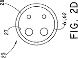
本発明の或る実施形態では、突起28は、内視鏡挿入部の一部を受け入れることができるように作られ、挿入部61の周囲64(外周面)を留め、握り、把持し、摘み、締め、引っ掛け、接合し、又は他のやり方で保持する(総称的に「クリップ」「クリップ留め」及びその派生語とする)ことができるようになっている、挿入部受け入れ空洞29を形成する対称又は非対称の何らかの適した構造である。図2A、2B、2Cは、挿入部を少なくとも部分的には取り囲む、一部が欠けた環状構造の様なクリップの一例を示している。図2A、2B、2Cに示す基部23構造は、支持部材20並びに関節運動本体部30(後述)と共に使用される。また、関節運動本体部30は、図2D、2E、2Fに示す基部23構造を使用しており、ここで、クリップは、リング型構造(「リングクリップ」又は場合によっては「エンドクリップ」と呼ばれる)の様に挿入部を取り囲むか、又は図2E、2Fに仮想線で示すように一部を取り除くことにより、挿入部を部分的に取り囲む。図2Eは、基部23’と、複数の通路22が同一面に概略整列しているガイド部21’を有する代わりの実施形態110を示しており、他方、図2Fの実施形態では、基部23”とガイド部21”を有し、複数の通路22が間隔を開けて配置されている。上で示し、説明した基部クリップとリングクリップは、内視鏡の挿入部及び/又は先端部分に取り外し可能に係合させる保持部材を二例挙げたものである。
In an embodiment of the present invention, the
支持部材の基部23の上記設計は、以下に説明するように、挿入部の先端62に対して関節運動本体部を保持するために関節運動本体部に組み込まれている。
(関節運動本体部)
The above design of the
(Joint movement body)
図3に示すように、関節運動本体部30は、第1部分31と、連結部19によって第1部分31に関節運動可能に連結されている第2部分32とを備えている。
As shown in FIG. 3, the articulation
ここで、関節式とは、運動可能であることを意味し、並進変位、及び/又は、回転の全自由度を含んでいる。例えば、関節運動とは、軸線方向、長手方向、前方、後方、直交方向、側面方向、横断方向、自転、旋回、上り又は下り傾斜、揺動、ねじれ、軸回り回転及び他の形態の、x、y、及び/又は、z座標系内の並進、及び/又は、回転である(総称的に「関節運動」、[関節運動する]、「関節運動可能な」、「関節式で」及びそれらの派生語で表す)。 Here, articulated means that it can move, and includes translational displacement and / or total degrees of freedom of rotation. For example, articulation refers to axial, longitudinal, forward, backward, orthogonal, lateral, transverse, rotation, turning, up or down tilt, rocking, twisting, rotation around axis, and other forms of x , Y, and / or z translations and / or rotations in the coordinate system (collectively “articulated”, “articulated”, “articulatable”, “articulated” and those Is a derivative of).
関節運動は、関節運動基準系に関して生じる。関節運動基準系は、そこを中心に並進、及び/又は、回転運動範囲が定められるあらゆる軸、継手、ボール、軸受け、回転中心、支点、レバー、ヒンジ、実線又は仮想線、又は基準点(総称的に、「基準系」又は「関節運動基準系」)を含んでいる。例えば、回転1自由度系では、関節運動基準系は軸であり、回転多自由度系では、関節運動基準系は、ボール内の基準点とそこを通る軸である。 Articulation occurs with respect to the articulation reference system. An articulation reference system is any axis, joint, ball, bearing, center of rotation, fulcrum, lever, hinge, solid or imaginary line, or reference point (generic name) that is translated and / or rotationally defined around it. In particular, it includes a “reference system” or “joint motion reference system”). For example, in a rotational one degree of freedom system, the joint motion reference system is an axis, and in a rotational multi-degree of freedom system, the joint motion reference system is a reference point in the ball and an axis passing therethrough.
第1部分31は、関節運動する第2部分32を挿入部61の先端部分62に連絡のある状態で(即ち、間接的に)接合するようになっている。第1部分31は、先端31、基端31、及び保持部材23を有している。保持部材は、挿入部61の先端部分62に取り外し可能に係合させるための、図2Aから2Fに関して先に説明したような何らかの適した基部23であってもよい。
The
そのように、保持部材23は、第1長手方向軸線39と挿入部当接面27(以下「当接面27」及び/又は「挿入部当接面27」)とを有する挿入部受け入れ空洞29(以下、「空洞29」及び/又は「挿入部受け入れ空洞29」)を画定している少なくとも1つの挿入部クリップ留め突起28(以下、「突起28」、「各突起28」及び/又は「挿入部クリップ留め突起28」とする)を含んでいる。図2A、2B、2Cに示すように「クリップ」を形成している部分的に取り囲む型式の保持部材は、挿入部の各側部を挟んでいる、例えば脚の様な片持ち梁に似ている。ここで、「側部」という用語は、非限定的に、例えば挿入部の外周64のような、円筒の周囲、又は実質的に管状の外周を有する環状のシース又は挿入部の外面についても、使用する。換言すると、突起部23の、挟んでいる脚は、第1部分31を挿入部先端部分62に保持するために、挿入部の互いに反対側に万力のような力を働かせる。突起28、挿入部当接面27、及び挿入部受け入れ空洞29を備えている保持部材23の代わりの形状としては、挿入部61の先端部分62にスナップ装着されこれを保持する、サドル、U字形、又はΩ字形(馬蹄型)のクリップ設計が挙げられる。突起部28を挿入部61の先端部分62の外周にスナップ装着することができるように、突起部28は、随意的に、十分にしなやかで弾性的形状記憶特性を備えている。また、図2Bに示すように、突起部28は、傾斜効果を提供することにより挿入部へのクリップ留めをやり易くするか、又は突起部28の組成が拡張に抵抗する性質である場合のクリップ留めをやり易くする逆向きの突起53、54を有してもよい。図2D−2Fに示す「リングクリップ」の場合のように周囲を取り囲む方式、又は図2A、2B、2Cに示すように部分的に取り囲む方式の突起28を含む型式の保持部材23は、摩擦装着を形成するために内径50が挿入部61又は挿入部の先端部分62の外径51よりも小さくなっている。
As such, the holding
挿入部挟持用突起28は、挿入部61の先端部分62の箇所又はその付近に取り外し可能に係合する。「その箇所又は付近」という用語は、挿入部挟持用突起28が挿入部61の先端部分62に、同一面となるか又はオフセットして係合してもよいことを意味する。「オフセット」という用語は、第1部分31の先端31’が挿入部61の先端部分62の先端面と同一面内にないことを意味する。言い換えると、先端31’は、挿入部61の先端部分62から後退しているか先端部分62を越えて伸張している。
The insertion
保持部材23が挿入部61の先端部分62に取り外し可能に係合すると、第1部分の長手方向軸39は、挿入部の先端部分に対して同軸、平行、又は固定された関係になる。換言すると、保持部材23は、保持部材23と挿入部先端部分62が同心又は一致するように、挿入部先端部分62に取り外し可能に係合する。代わりに、長手方向軸39は挿入部61の先端部分62とオフセットしてはいるが実質的に平行であってもよい。また別の例では、保持部材23の長手方向軸39と挿入部61の先端部分62の長手方向軸は、同一(収束する)の方向か、又は異なる(発散する)方向かの何れかの方向に伸張するように固定される;言い換えると、両者の角度関係は、実質的に固定されているが平行ではない。これらの代替案では、第1部分31は不動であると言え、第1部分31は、挿入部61の先端部分62から独立して関節運動を行わないことを意味する。即ち、挿入部61の先端部分62の軸が、本体部30に対して基準系内で並進及び/又は回転する場合には、関節式本体部30の保持部材23は、実質的に相伴った並進及び/又は回転を行う。
When the holding
第2部分32は、概して、第1部分31に対して関節運動ができるようになっている。或る実施形態では、第2部分32は、少なくとも1つの関節リンク部材36と取付部材37を備えた連結部19を介して第1部分31に連結される付属チャネル部材11の第2端13である(後述)。別の実施形態では、第2部分32は、第2端チャネル部材が固定されるプレートである。
The
第2部分32の別の代わりの実施形態は位置決め部材であり、これは付属チャネル部材11の第2端13を関節運動させることができるように作られた構造体である。或る実施形態では、位置決め部材は、付属チャネル部材11の第2端13を滑動可能に保持するように作られており、チャネル部材11の第2端13が関節運動時に滑動することができるようにする滑り嵌合部が形成されている。代わりの実施形態では、位置決め部材は、チャネル部材第2端13の一部に結合するかこれを拘束して、挿入部61の先端部分62の視界に対してチャネル部材11の第2端13の向きを定め又は位置を変えることができるように作ることができる。
Another alternative embodiment of the
位置決め部材である第2部分13の或る非限定的な例は、先に説明したように、全円周型又は円周が一部途切れた構成のカニューレ、管、ダクト、導管、又は通路33を画定する他の管状構造を含んでおり、付属チャネル部材11の第2端13を固定的に受け入れることができる大きさに作られていて、このチャネル部材の第2端13が、通路33内に軸線方向に、嵌合され、挿入され、入れ子にされ、配置され、又は位置決めされている。管状の位置決め部材は、数例を挙げると、摩擦、接着剤、膠、刺、又はそれらの組み合わせでチャネル部材11の第2端13に固定してもよいし、付属チャネル部材11の第2端13を滑り嵌合により拘束してもよい(総称的に「装着された」)。
One non-limiting example of the
チャネル部材11の第2端32の別の結合例は、第2部分32が管状の位置決め部材(全円周型又は切り取り型のいずれか)であって、付属チャネル部材側(例えば、内側)と、第2の反対側(例えば、外側)を有し、付属チャネル部材側は、チャネル部材を保持するために接着層(例えば、接着剤)を有している。接着剤の代わりに又はこれに加えて、摩擦によってチャネル部材を位置決め部材に対して保持することができ、その場合には、例えば、管状の位置決め部材は、第1断面積を有する第1部分と第1断面積よりも小さい第2断面積を有する第2部分を備えている。摩擦装着の別の実施例では、第2部分32が、実質的に筒状の第1部分と第2の先細部分を有する管状の位置決め部材である。上記摩擦装着の例では、付属チャネル部材11の第2端13は、管状の位置決め部材通路33内に軸方向に(第1断面積を有するか又は実質的に筒状である基端側開口部34の中に)入れられ、管状の位置決め部材通路33内を(小さな第2断面積を有するか又は先細になっている先端側開口部35に向けて)軸方向に動く際にぴったりと嵌合する。
Another coupling example of the
本発明の他の特徴についてと同様に、位置決め部材である第2部分32は、先に説明したように、適していればどの様な材料(天然材料、合成材料、プラスチック、ゴム、金属、セラミック、ポリマー、又はそれらの組み合わせ)で作ってもよい。患者に接触する可能性がある場合、位置決め部材は、生体適合性を有するか、被覆、化学処理などで生体適合性を持たせた材料で構成される。更に、位置決め部材は、機械加工、切削、圧延、押し出し、型成形、又は適した何らかの手段で形成してもよく、付属チャネル部材11の第2端13に対して一体的に予成形してもよい。
As with the other features of the present invention, the
また、第2部分32は長手方向軸線38を含んでいる。例えば、管状の位置決め部材の長手方向軸線38は、管状の位置決め部材に対称か、又はこれを二等分する実質的に真っ直の、一定の、又は、湾曲した仮想線である。第2部分32の長手方向軸線38は、第1部分31又は挿入部61の先端部分62の長手方向軸線39に対して可動である。第2部分32は、概して、付属チャネル部材11の第2端13に適合するように構成され、関節リンク部材36と取り付け部材37で第1部分31に連結され、第2部分32の長手方向軸線38が第1部分31に付帯して、第1部分の長手方向軸線39の様な関節運動基準系回りに動くことができるように、第1部分31に対して関節運動する。
(出口軌道)
(Exit trajectory)
次に、本発明の実施形態と共に使用される器具の抜け出し軌道について説明する。上記説明から、当然のことながら、第2部分32と第1部分31は、第2部分32が1又はそれ以上の回転及び/又は並進自由度で関節運動できるように、少なくとも1つの関節リンク部材36と取り付け部材37とを備えている連結部19(後述)を介して連結されている。例えば、或る実施形態は、回転2自由度と並進2自由度で合計4自由度である。別の例は、回転3自由度と並進2自由度で合計5自由度である。多くの組み合わせが想定され、従って、系には1自由度のものから多自由度のものまである。
Next, the exit trajectory of the instrument used with the embodiment of the present invention will be described. From the above description, it will be appreciated that the
こうして、器具は、付属チャネル部材ルーメン15に挿入され、第2部分32の先端側開口部35から抜けて出て行き、又はそこから伸張する。第2部分32は、(例えば、第1部分の長手方向軸線39の様な)関節運動基準系内で回転及び/又は並進の自由度で関節運動するので、第2部分32は、第2部分32の先端側開口部35から伸張する器具の出口軌道又は器具の位置が制御できるやり方で、操縦され、位置決めされ、向きを定められる。この様に、医師は、内視鏡観察野及び作業空間内の器具の位置及び/又は向きを、第2部分32を関節運動させることにより制御することができる。
(関節リンク部材)
Thus, the instrument is inserted into the attached
(Joint link member)
回転及び/又は並進自由度系では、第2部分は、1つ又はそれ以上の連結部19により、第1部分31に関係付けられており、この連結部19は、第2部分32が直接的に又は連結部を介して間接的に第1部分31と連絡して、第1部分31に対して関節運動することができるように、又は第2長手方向軸線38が第1長手方向軸線39に対して動けるように、第1及び第2部分31、32それぞれを連結することができるように構成された何らかの構造又は機構である。従って、第1及び第2部分は、少なくとも1つの関節リンク部材36と取付部材37とを備えた連結部19を介して関節運動可能に連結されている。
In a rotational and / or translational degree of freedom system, the second part is related to the
関節リンク部材36の或る非限定的な例としては、全体的又は部分的を問わず、軸受け、ピン、シャフト、ねじ、ロッド、バー、ボール又は半球状ボール、支点、継手、支持部、スプロケット、ホイール、隆起、突出部、突起又は他のリンケージ(総称的に「関節リンク部材」)を挙げることができる。当然の事ながら、関節リンク部材36は、関節運動をやり易くするために、面取りされた、傾斜を付けられた、平坦な、先の尖った、矩形の、直円錐の、三角形の、管状の又は丸くなった、設計としてもよい。また、当然の事ながら、関節リンク部材36は、関節運動基準系を画定している運動範囲と合致する様々な形状を取ることができる。
Some non-limiting examples of the
関節リンク部材36は、第1部分31、第2部分32、又は第1部分と第2部分を連結する構造体の何れに設けてもよいし、或いは、第1部分と第2部分を連結する(即ち、第2体32を直接的に又は関節運動リンク部材36を介して間接的に第1部分31と関節運動可能に連絡させることができる)構造を備えてもよい。関節運動リンク部材36が第2部分32側に設けられている場合には、例えば、第1部分31は、相手方の関節運動リンク部材36を受け入れて関節運動可能に保持するように設計された1つ又はそれ以上の関節運動リンク部材受け入れ部36’を有している。同じ例で、関節運動リンク部材36が第1部分31側に設けられている場合には、1つ又はそれ以上の関節運動リンク部材受け入れ部36’は、第2部分32側に設けられる。各部分31、32それぞれに、関節リンク部材36と受け入れ部36’の両方を設けてもよい。
The
関節リンク部材受け入れ部36’の非限定的な例としては、スロット、チャンバ、インデント、へこみ、陥凹、孔、切り抜き、空洞、又は他の輪郭を有する支承面が挙げられるが、これらに限定されるものではない。また、受け入れ部36’とリンク部材36は、面間の摩擦を小さくするためポリテトラフルオロエチレンの様な低摩擦材料又は潤滑材料で被覆又は部分的に被覆してもよい。また、受け入れ部36’とリンク部材36は、ナット、ボルト、スクリュー、ねじ、コッターとピン、又はばね付勢の様な適切な固定機構を使用することができる。
Non-limiting examples of articulation link member receiving portion 36 'include, but are not limited to, bearing surfaces having slots, chambers, indents, dents, recesses, holes, cutouts, cavities, or other contours. It is not something. Further, the receiving
1、2、又は3の回転自由度及び/又は1又はそれ以上の並進自由度を有している実施形態があり得るので、2つ以上の関節リンク部材36と受け入れ部36’があり得る。また、実施形態は、一致するか又は等しくない個数のリンク部材36と受け入れ部36’を有していてもよい。図面中の参照番号36と36’は、一般には、関節リンク部材及び/又は関節リンク部材受け入れ部を指している。従って、図面に36’無しで36が示されている場合には、この36は、関節リンク部材又は関節リンク部材受け入れ部である。
(1自由度)
Since there may be embodiments having one, two, or three rotational degrees of freedom and / or one or more translational degrees of freedom, there may be more than one articulated
(1 degree of freedom)
関節運動本体部30の或る実施形態は、1自由度系を採用することができる。これは並進でも回転でもよい。並進1自由度系の例には、X−Zテーブルがあり、第2部分32がX又はZの何れかの方向に変位する。1回転自由度系の例には、ピッチ又はヨー系がある。第1部分31を基準として選択した場合、ヨー系は、第2部分32が第1部分31に対してヨー基準系(例えば軸)回りに一方の側から他方の側まで関節運動することができるようにし、ピッチ系は、第2部分32が第1部分31に対してピッチ基準系(例えば軸)回りに上方又は下方へ関節運動できるようにする。
Certain embodiments of
第2部分32は、(上記)関節リンク部材36によって、ヨー又はピッチの関節運動基準系回りに動けるように第1部分31に取り付けられている。ここに開示し図面に示している本発明の実施形態を説明する目的で使用する場合、「取り付けられる」とは、第2部分32を第1部分31に、直接的に又は取付部材37と関節リンク部材37とを備えている連結部19を介して間接的に、可動的に連絡させるあらゆる装置を含んでいる。取付部材37の或る非限定的な例としては、ブラケット、ヨーク、受け台、ブロック、プレート、又は1つ又はそれ以上の上記関節リンク部材36と受け入れ部36’とを使用した他の雄雌形連結器を挙げることができる。上記取付部材37は、第1及び第2部分31、32それぞれに連結することから、関節リンク部材36と見なすこともできる。取り付け部材37は、第1部分31か第2部分32の何れか一方に設けてもよいし、第1及び第2部分31、32それぞれに連結するために各部分に設けられた構造体であってもよい。
The
図3A、3B、3Cは、回転1自由度系を使用する関節運動本体部30の代わりの実施形態を示している。図3Aは、内視鏡挿入部61の先端部分62の外周64又は付近に長手方向に設定されている第2端13を有する付属チャネル部材11を備えている或る実施形態の先端区間の部分斜視図を示している。また、付属チャネル部材11を挿入部61に橋架けするために設けられている随意的な支持部材20も図示されている。支持部材20は、先に説明したように、基端側及び先端側開口部24、25それぞれを有し、付属チャネル部材11を受け入れるための通路22を形成しているガイド部21と、挿入部61の外周64に取り外し可能に係合させるための基部23とを含んでいる。図3Aの支持部材20は、随意的なコネクタ41を受け入れるように構成された随意的な補助ルーメン26も有しており、このルーメンは、後述するが、制御装置40(図示せず)を関節運動本体部30の箇所又はその付近に設けられたアクチュエータ42(図示せず)に作動可能に接続するものである。
3A, 3B, and 3C show an alternative embodiment of the
関節運動本体部30は、先に説明したように、本体部30を挿入部61の先端部分62に保持するための第1部分31を備えている。また、第2部分32は、付属チャネル部材11の第2端13を固定するが、ここで実施形態を説明する際の「固定された」という用語は、関節運動可能に、滑動可能に、伸縮可能に、又は固定的に、を含んでいる。第2部分32は、先に説明したように、基端側及び先端側開口部34、35それぞれを有しており、通路33を形成し、付属チャネル部材11の第2端13が第2部分の通路33内の基端側開口部34と先端側開口部35の間に軸方向に配置されるか、又は先端側開口部35の先端より外側に向けて伸張するようにしている。先端側開口部35は、第1部分保持部材23の外側(第1部分31の先端31’に対して先端側)の空間に向けて配置されている。
As described above, the joint motion
2つの水平な関節リンク部材36は、ピッチ型関節運動基準系を形成しており、第2部分32の基端側34と先端側35のほぼ中間に在って、第2部分32を第1部分31に図3A、3B、3Cの取付部材37を介して、直接的に又は間接的に、関節運動可能に連結するものとして示されている。図3Aと3Bのリンク部材36の中間位置は、第2部分32の基端側及び先端側開口部それぞれ34、35の揺動を許容する。リンク部材36が図3Aと3Bのように中間に配置されている場合、第2部分32の第1部分31に対する関節運動の許容角度は、第1部分31と第2部分32の間のクリアランスの高さによって制限される。ヨーイング系では、取付部材37は、第2部分32の取付部材37に対する幅又は距離間隔がヨー拘束量となり、その拘束量だけ第2部分32の関節運動を制限する機能を果たすことになる。
The two horizontal
図3Bは、回転1自由度系の代わりの実施形態である。二点鎖線は、第2部分32の長手方向軸38と第1部分31の長手方向軸39を概略的に示している。挿入部61の先端部分62は、挿入部受け入れ空洞29(図示せず)を占有している。図3Bでは、長手方向軸線39は、挿入部61の先端部分62と同軸に示されている。第2部分32の先端側開口部35は、導入部61の先端部分62及び第1部分31の外側の空間に向けて図3Bにθと示された関節運動角度40で配置されている。また、関節運動本体部30がアクチュエータ(図示していないが、図3Aの関節運動本体部30内に随意的に含まれている)を含んでいる図3Aと比較して、図3Bでは、アクチュエータ42は、関節運動本体部30に近接して設けられた別の構成要素であり、遠隔の制御装置40(図示せず)から随意的なコネクタ41を介して操作されるものとして示されている。
FIG. 3B is an alternative embodiment of a rotational one degree of freedom system. The two-dot chain line schematically shows the
図3Cは、図3Aの回転1自由度系の代わりの実施形態である。しかしながら、2つの水平な関節リンク部材36は、先端方向に配置されており、第2部分の先端開口部35又はその付近にピッチ軸を形成している。第2部分32の先端側開口部35は、挿入部61の先端部分62及び第1部分31の外側の空間に向けてαで示す関節運動角度で配置されている。
(2自由度)
FIG. 3C is an alternative embodiment of the rotational one degree of freedom system of FIG. 3A. However, the two horizontal
(2 degrees of freedom)
関節運動本体部30の別の実施形態は、少なくとも2自由度の系を使用することができる。これは、並進、回転、又はその組み合わせでもよい。例えば、並進1自由度系(後に述べるがX−ZテーブルのX又はZ方向として)を図3A、3B、又は3Cに組み込んで、合計2自由度とする。後述の別の非限定的な例では、実施形態は、回転2自由度と並進2自由度を有している。
Another embodiment of the
回転2自由度の例は、ピッチ・ヨー系を含んでおり、その様な装置の一例はジンバルである。第1部分31を基準として選定した場合、ピッチ・ヨー系は、第1部分に対する第2部分のヨー基準系回りの一方の側から他方の側への関節運動を可能にすると共に、第1部分に対する第2部分のピッチ基準系回りの上方又は下方への関節運動も許容する。
Examples of two degrees of rotation include a pitch / yaw system, and an example of such a device is a gimbal. When the
図4Aは、第1部分(図示せず)と第2部分72を有する関節運動本体部30の斜視図であり、第1及び第2部分はこれまでに説明したものである。本体部70は、ジンバル式ピッチ・ヨー系の様な2関節運動基準系を選択採用している。連結部19は、取り付け部材77と、第2部分72を関節運動リンク部材78により画定されたヨー基準系回りに関節運動させる関節リンク部材78とを備えている。第2部分72は、関節リンク部材76により画定されたピッチ基準系回りの関節運動も行う。
FIG. 4A is a perspective view of the articulation
図4Bは、図4Aの代わりの実施形態であり、回転2自由度で並進2自由度の例を示している。連結部19は、X−Zテーブルに嵌め込まれた関節運動するリンク部材78を有している。ここで、X−Zテーブルは、X方向及び/又はZ方向に変位させることができる並進プレート43として示されている。従って、並進プレートが回転2自由度系の関節リンク部材に連結されると、第2部分は、回転2自由度を有し、且つX及び/又はZ方向にも変位させることができ、合計4自由度となる。
FIG. 4B is an alternative embodiment of FIG. 4A, showing an example of translational 2 degrees of freedom with 2 degrees of freedom of rotation. The connecting
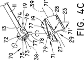
図4Cは、先に説明した第1部分71と第2部分72を有する関節運動本体部70を示しており、この関節運動本体部70は、2自由度系を採用している。図4Cは、実施形態の先端区間の部分分解斜視図において、2自由度の関節運動本体部70を強調して示した図である。また、第2部分72の先端側開口部75と基端側開口部74の中間の通路73に配置された付属チャネル部材11の第2端13の図も示している。関節運動本体部70は、挿入部61(図示せず)の先端側端部分62に取り外し可能に係合させるように構成された第1部分70を更に備えている。
FIG. 4C shows the joint motion
連結部19は、取り付け部材77と関節運動リンク部材78を介して第2部分72を第1部分71に関節運動可能に連結するピッチ基準系を形成している水平な関節運動リンク部材76を含んでいる。別の連結部19は、ヨー基準系を形成し且つ取り付け部材77を第1部分71に関節運動可能に取り付けるために関節リンク部材受け入れ部79に受け入れられる、垂直な関節運動リンク部材78を備えている。
The connecting
図4Dは、図4Cの代わりの実施形態であり、回転2自由度で並進2自由度の例を示している。関節運動リンク部材78は、並進プレート43として図示されているX−Zテーブルの関節リンク部材受け入れ部79に嵌め込まれている。並進プレート43は、関節運動リンク部材78を固定的又は関節運動可能に固定するための取り付け部材として機能する。並進プレート43は、並進プレート43が浮き上がって外れないようにするために、第1部分フランジ受け入れ部45と協調するフランジ44を備えている。並進プレートは、フランジ44が、そしてその結果として並進プレート43が関節運動(本例では並進型)できるように構成された第1部分フランジ受け入れ部45に受け入れられる関節リンク部材として機能するフランジ44を介して、X方向及び/又はZ方向に変位させることができる。図4Eは、並進2自由度の実施形態の概略図である。並進プレート43を図4Dに示す回転関節リンク部材に連結させると、第2部分72は回転2自由度を有し、且つX及び/又はZ方向に変位させることができ、合計4自由度となる。
(多自由度)
FIG. 4D is an alternative embodiment of FIG. 4C and shows an example of translational 2 degrees of freedom with 2 degrees of freedom of rotation. The
(Multiple degrees of freedom)
関節運動本体部80の別の実施形態では、少なくとも多自由度系を採用している。これは、並進、回転、又はそれらの組み合わせであってもよい。多自由度系の一例には、ピッチ・ヨー・ロール系が含まれ、他方、別の例は、ボール・ソケット系を備えている。
In another embodiment of the
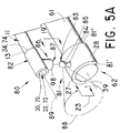
図5Aは、関節運動本体部80の部分分解斜視図であり、或る実施形態の先端部分を示したものであるが、ボール・ソケット継手装置である連結部19を介して間接的に互いに作動可能に接合されるように作られた第1及び第2部分それぞれ81、82を備えている回転多自由度系を採用した関節運動本体部80を強調して示している。
FIG. 5A is a partially exploded perspective view of the
ボール・ソケット継手装置は、第1部分81の或る領域から突き出たボール部分83を備えた関節運動リンク部材を有し、更に隣接する第2部分82に設けられたソケット部86を備えている対応相手の関節運動リンク部材を有している。図5Aのボール部分83とソケット部分86は、第1及び第2部分それぞれ81、82上に示されているが、それらの相対位置は、ボール部分83を第2部分82上に配しソケット部分86を第1部分81上に配することにより、入れ替え可能である。
The ball and socket joint device includes an articulation link member having a
図5Aでは、ボール部分83は、茎部84に支持されているノブ85を有しており、ソケット部分86は、ノブ85を関節運動可能に受け入れるソケット87を有している。ボール・ソケット継手装置の或る実施形態では、ソケット部分87には、内部にソケットを有する成形空洞が設けられている。
In FIG. 5A, the
この分解図である図5Aの二点鎖線は、第2部分82のボール83の関節運動基準系回りの運動範囲を参照番号88で示しているが、当然の事ながら、関節運動基準系はソケット部87に関して描くこともできる。図5Aは、中立位置での出口軌道に相当する、又は第1部分81の長手方向軸線39に関して、又は挿入部61の先端部分62に関して、の何れかに対応する第2部分の長手方向軸線89も示している。
The two-dot chain line in FIG. 5A, which is an exploded view, shows the range of motion of the
ソケット部86に形成されている成形空洞は、茎部84の関節運動の所望の範囲を定めるために利用することができる。この運動量の制限は、ソケット部86が、ソケット87内での茎部84の運動の範囲を決める側壁98を有することで実現される。換言すれば、第2部分87がノブ(ボール)85回りに関節運動すると、茎部84はソケット部86の側壁98に当たる。この原理を使うと、先端側及び基端側の弓状切り取り部を有するソケット部86は、より大きなピッチ運動量を有し、ヨー関節運動は、側方の側壁で制限されることになる。反対に、弓状の切り取り部を、先端側/基端側側壁ではなく側方に有しているソケット部86では、一般にピッチ方向よりもヨー方向への関節運動量が大きくなる。更に、ソケット部86が(比喩的表現として)ノブ85の赤道をほんの僅かに南に下った短尺の側壁を有する場合、ソケット部86は、ピッチ方向、ヨー方向、及びロール方向の関節運動量が、長尺側壁の場合よりも大きくなる。
The molded cavity formed in the
図5Bは、図5Aの代わりの実施形態であり、更に並進2自由度が可能なことを示している。茎部84は並進プレート43に嵌合しており、プレート43をX方向及び/又はZ方向に変位させることができるようになっている。なお、当然のことながら、並進プレート43は、先に図4Dの内容に関して図示し説明したように、並進プレートが浮き上がって外れるのを防ぐために第1部分のフランジ45と協調するフランジ44を有していてもよい。従って、第2部分82は回転多自由度と並進2自由度を有している。
(制御装置、コネクタ、及びアクチュエータ)
FIG. 5B is an alternative embodiment of FIG. 5A and shows that further two translational degrees of freedom are possible. The
(Control device, connector, and actuator)
図1には、制御装置40が概略的に示されている。制御装置は、装置10の一部であってもよいし、装置10から分岐して取り外し可能(分離可能)であってもよいし、支持部材20で付属チャネル部アダプタ14に取り付けてもよいし、無線遠隔制御装置であってもよい。制御装置40は、医師、手術者、又は医療専門家の手の届く範囲に配置され、通常(必ずしもではないが)、装置10の基端側第1端12に設けられている。制御装置40は、1つ又はそれ以上の各自由度に合わせて1つ又はそれ以上のアクチュエータ42、90、90’を遠隔的に、選択的に、且つ連絡的に調整し、そのアクチュエータは、コネクタ41を介して、機器10の関節運動本体部30又はその付近に設けられている(図1では不図示)が、無線制御装置の場合には、コネクタ41は不要である。
FIG. 1 schematically shows the
制御装置40は、ワイヤ又はケーブルを動かす機械的ハンドル、水又は他の液体を調整してピストンとシリンダを動かす油圧ハンドル、空気又は他の気体の流れを調整する空圧入力/出力(空気圧式)、又は1つ又は複数の電気スイッチであってもよい。制御装置40からは、コネクタ41が先端方向に伸張している(無線遠隔制御装置の場合を除く)。コネクタ41は、制御装置40又はその付近から、関節運動本体部30又はその付近に設けられた1つ又はそれ以上のアクチュエータ42、90、90’まで伸張させることができる機構(例えば、細長い機械的ワイヤ、ロッド、シャフト、ケーブル、及びシース;細長い空圧配管又は油圧流路;又は電気導体)である。コネクタ41は、適当な管状構造内に収納されていてもよい。
The
図6A、6B、6Cは、作動時のアクチュエータ90の或る実施形態を概略的に示した側面断面図である。図示のように、アクチュエータ90の1つの考えられる実施形態は、第1部分91に対する第2部分92の関節運動(例えば、図6Bの双頭矢印97の方向)をやり易くする回転軸93(例えば、クランク)である。クランクは、第2部分92の角度を調節し、このようにして、第2部分92のスロット95内に捕捉されているクランク端のオフセット部94(図6B参照)を回転させることにより、第2部分92の先端の先端側開口部から抜け出し又は伸張することのできる器具の位置及び/又は向きを制御する。
6A, 6B, 6C are side cross-sectional views schematically illustrating an embodiment of the
図6Dは、図6Aの6D−6D線に沿う断面図である。この図は、回転軸93のオフセット端部94の円形の回転96を示しており、オフセット端部94は、作動スロット95内を動いて、第2部分92の長手方向軸線38を垂直に両方向(双頭矢印97の方向)に関節運動させる。図6Eは、ボール85・ソケット86アッセンブリを使用するクランク機構を装着することによる、本発明の3自由度関節運動(例えば、双頭矢印97の方向に円周状360度の回転)の実施形態のアクチュエータ90の側部断面図である。この運動は、クランクオフセット端94をスロットではなく孔99に入れることによって生まれる。上記は、1自由度の軸又は多自由度のボール・ソケット回りの関節運動をやり易くする機械的アクチュエータの数例を示したに過ぎない。当然の事ながら、機械的アクチュエータは、電気機械的アクチュエータとして、電気により作動させもよい。
6D is a cross-sectional view taken along
図6Fは、図6Dのアクチュエータ90と、垂直方向のスロットを含んでいる図6Dの代替版アクチュエータ90’とを組み込んだ、2個のアクチュエータ90、90’を使った実施形態の端部断面図である。図6Fでは、第1アクチュエータ90は、第2部分92の水平方向スロット95内に捕捉され、旋回回転96回りに動いて第2部分92をピッチ基準系回りに関節運動させるクランク端オフセット部94を含んでいる。第2アクチュエータ90’は、第1部分91の垂直なスロット95’内に捕捉され旋回回転96’回りに動いて第2部分92をヨー基準系回りに関節運動させるクランク端オフセット部94’を含んでいる。
6F is an end cross-sectional view of an embodiment using two
図7Aは、第2部分92の、関節運動リンク部材36の様な垂直方向基準系回りの回転(ヨー)をやり易くするためのピニオン66とギヤ65を備えているアクチュエータ90を示している。図7Aの水平なギヤ65とは対照的に、図7Bのアクチュエータ90は、垂直なギヤ65を備えている。図7Bのピニオン66の回転により、関節運動リンク部材36の様な水平方向基準系回りの回転(ピッチ)がやり易くなる。
FIG. 7A shows an
アクチュエータ90の別の非限定的な例として、図7Cに示すジャッキスクリュー装置を使用してもよい。ジャッキスクリュー装置を使用したこの実施形態では、第1部分(図示せず)と第2部分92の間に、そしてピボットピン(関節リンク部材)の後にボルトが配置される。ボルト67は、ねじ式ギヤ68の中で上下に回されて、第2部分92の基端を、関節リンク部材36のピッチの様に、水平な基準系周りに軸回転する変位を生じさせる。
As another non-limiting example of the
図8Aは、複動空圧(又は油圧)シリンダアクチュエータ113を有する代わりのアクチュエータ90の実施形態の概略側面図である。シリンダが作動すると第2部分112が変位する。図8Bと8Cは、代わりのアクチュエータ90実施形態の概略側面図であり、それぞれ、戻しばね115を備えた少なくとも単動式の空圧(又は油圧)シリンダアクチュエータ114を備えている。図8Bは、弛緩状態のばね115を示しており、図8Cは、第2部分を元の位置に戻すのに必要な力を供給している緊張状態にある戻しばね115を示している。
FIG. 8A is a schematic side view of an embodiment of an
当業者には当然のことながら、アクチュエータは、電子的、空圧的、油圧的、機械的な動力源、又はそれら動力源の組み合わせを含む様々な動力源を利用して、第2部分を、第1部分又は第1部分の長手方向軸に対して、上下方向、横方向、及び/又は更に別種の様式で動かすことができる。動力源は、制御装置及び/又はアクチュエータに設けられてもよい。また、アクチュエータは、機械的作動要素、電子的作動要素、電気機械的作動要素、空圧的作動要素、油圧的作動要素、圧電スティック・スリップ式、熱機械的、及び化学機械的要素を利用してもよい。 As will be appreciated by those skilled in the art, the actuator utilizes a variety of power sources, including electronic, pneumatic, hydraulic, mechanical power sources, or a combination of these power sources, and the second portion, The first part or the longitudinal axis of the first part can be moved up and down, laterally, and / or in a different manner. The power source may be provided in the control device and / or the actuator. Actuators utilize mechanical, electronic, electromechanical, pneumatic, hydraulic, piezoelectric stick-slip, thermomechanical, and chemical mechanical elements. May be.
例えば、アクチュエータの代わりの実施形態は、直線状アクチュエータロッドを使用したモーター・リンケージ系である。モーターは、第2部分の少なくとも1つのレバーアームに回動可能に接続された少なくとも1つの直線状アクチュエータに接続されており;直線状アクチュエータの伸長又は収縮により、レバーアームが第2部分をピボット点又は軸回りに関節運動させて、第2部分の傾斜の増減を調整する。他に、ラック・ピニオン系を利用したアクチュエータがある。更には、空圧手段が膨張すると第2部分が第1方向に傾斜し、空圧手段が萎むと第2方向に傾斜するようにした、空圧式(例えば、バルーン)を使用するものもある。また、ピストン及びシリンダと共に油圧ケーブルを使用するものもある。アクチュエータとしては、他にカムが考えられ、その場合、回動又は滑動部品が機械的なリンクに設けられ、回転運動を直線運動に、又はその逆に変換する。
(方法)
For example, an alternative embodiment of an actuator is a motor linkage system using a linear actuator rod. The motor is connected to at least one linear actuator pivotally connected to at least one lever arm of the second part; the extension or contraction of the linear actuator causes the lever arm to pivot the second part. Alternatively, the increase or decrease of the inclination of the second portion is adjusted by articulating about the axis. In addition, there is an actuator using a rack and pinion system. Further, there is a type using a pneumatic type (for example, a balloon) in which the second portion is inclined in the first direction when the pneumatic means is expanded, and is inclined in the second direction when the pneumatic means is deflated. Some use hydraulic cables with pistons and cylinders. Another possible actuator is a cam, in which case a rotating or sliding part is provided on the mechanical link to convert the rotational movement into a linear movement or vice versa.
(Method)
本発明は、内視鏡の先端に取り付けられた関節運動本体部を関節運動させることにより、内視鏡の先端側開口部の向こうの視野内にある器具の位置及び/又は向きを制御する方法も含んでいる。 The present invention relates to a method for controlling the position and / or orientation of an instrument in the field of view beyond the distal end opening of an endoscope by articulating an articulation main body attached to the distal end of the endoscope. Also included.
図9は、或る実施形態の方法100を示しており、この方法は、静止の第1部分31、71、81と、関節運動可能な第2部分32、72、82、92、112と、先に教示したように第2部分を第1部分に直接又は間接に連絡状態で関節運動可能に接合する連結部19を有する関節運動本体部を用意する段階(ステップ101)を含んでいる。第1部分は、先端31’、71’、81’と、基端31”、71”、81”と、第1長手方向軸線39を有している。第2部分は、付属チャネル通路33、73を画定する基端側開口部34、74と、先端側開口部35、75とを有し、先端側開口部は第1部分先端の外側の空間を向いた第2長手方向軸線38、89を有している。別の段階では、第1部分を、内視鏡挿入区間61の先端部分62に取り外し可能に係合させる(ステップ102)。第2部分を、第1部分に対して、少なくとも1自由度で関節運動させる(ステップ103)。随意的ではあるが、アクチュエータ42、90、90’を関節運動本体部又はその付近に制御装置41と連絡状態に設ける(ステップ104)。図10に示す別の随意的な段階(ステップ105)では、第1端12と第2端13を有する付属チャネル部材11を用意して、第2部分の通路33、73内に入れる。図11に示す更に別の随意的段階では、支持部材20を用意する(ステップ106)が、この支持部材はガイド部21と基部23とを有しており、ガイド部は基端側及び先端側開口部24、25を有し、付属チャネル部材を滑動可能に受け入れることができるように構成された通路22を画定しており、基部は一対の突起28の間に挿入部当接面27を有している。
FIG. 9 illustrates an embodiment method 100 that includes a stationary
別の方法は、第1及び第2部分を有する本体部を提供する段階(ステップ101)を含んでおり、この第2部分は、上記のように第1及び第2端を備え、付属チャネル部材を固定するルーメンを画定し、先端側開口部を有する、位置決め部材である。関節運動本体部を挿入部の先端部分に取り付け(ステップ102)、口、開口部、又は切開部を通して体内に入れて、内視鏡手術の部位に送り込む(ステップ103)。位置決め部材が関節運動できるように、関節運動本体部を作動させる(ステップ104)。 Another method includes providing a body portion having a first and second portion (step 101), the second portion comprising first and second ends, as described above, and an attached channel member. Is a positioning member that defines a lumen for fixing the front end and has a distal end side opening. The articulation main body is attached to the distal end portion of the insertion portion (step 102), inserted into the body through the mouth, opening, or incision, and sent to the site for endoscopic surgery (step 103). The articulation body is actuated so that the positioning member can articulate (step 104).
図10に示す更に別の方法100Aでは、診断用、監視用、内視鏡、縫い合わせ器具、切断器具、縫合器具、鉗子、把持器具、又は他の器具(総称的に「器具」)を、付属チャネル部材のルーメン内に軸方向に挿入する(ステップ105)。図11に示す更に別の方法100Bでは、付属チャネル部材が支持部材のルーメンに滑動可能に受け入れられるように支持部材を用意して、この支持部材を内視鏡挿入区間取り付ける(ステップ106)。
In yet another
器具の位置及び/又は向きを制御する方法は順序に従って実施する必要はない。例えば、上記各ステップは、省略しても組み合わせてもよく、内視鏡挿入区間(又は内視鏡を入れたシース)が、関節運動制御部材が既に取り付けられた状態で製作され、使用され、又は販売用に提供されている場合などがそうである(ステップ101、102)。更には、関節運動本体部を関節運動させ(ステップ103)、次いで器具を付属チャネルに軸線方向に挿入する(ステップ105)。同様に、支持部材を内視鏡挿入区間に取り付ける(ステップ106)のは、関節運動本体部を内視鏡挿入区間の先端に取り外し可能に係合させる(ステップ102)前でも、付属チャネル部材を患者体内に挿入する前でも、関節運動本体部を作動させる(ステップ103)前でもよい。
The method of controlling the position and / or orientation of the instrument need not be performed in order. For example, the above steps may be omitted or combined, and an endoscope insertion section (or a sheath containing an endoscope) is manufactured and used in a state where an articulation control member is already attached. Or the case where it is offered for sale (
医師の内視鏡観察野及び作業空間に器具を送り込んで器具の向きを制御する医療機器と方法についての上記の詳しい説明は、本発明を限定するものではなく、説明を目的としたものである。当然のことながら、本発明の精神と範囲を定義するのは、特許請求の範囲の内容並びにその全ての等価物である。用語にはそれらの妥当な意味が当てはめられ、類似の用語は特定の成果を実現する上で広義に入れ替え可能に使用される。従って、各図面及びその特徴の実施形態を、他の図面に示した実施形態と組み合わせることもできる。当技術で既知であり且つ本発明の構造と機能に矛盾しない他の特徴は、各実施形態に付け加えることができる。 The above detailed description of the medical device and method for controlling the orientation of the instrument by feeding the instrument into the endoscopic observation field and work space of the doctor is not intended to limit the present invention, but is intended to be illustrative. . Naturally, it is the content of the claims and all equivalents thereof that define the spirit and scope of the invention. Terms are given their reasonable meaning and similar terms are used interchangeably in a broad sense to achieve a particular outcome. Accordingly, the embodiments of each drawing and its features can be combined with the embodiments shown in other drawings. Other features known in the art and consistent with the structure and function of the present invention can be added to each embodiment.
以上、本発明の特有の要素、実施形態、及び応用例を示し説明してきたが、当業者であれば、特に上記教示に鑑み種々の変更を加えることができることから、無論のこと、本発明はそれらに限定されるものではない。従って、特許請求の範囲は、そのような変更は本発明の精神と範囲内に含まれる特徴を組み込むものとして、それらを包含するものとする。 As described above, the specific elements, embodiments, and application examples of the present invention have been shown and described. However, since various modifications can be made by those skilled in the art in view of the above teachings, the present invention is, of course, the present invention. It is not limited to them. Accordingly, the claims are intended to cover such modifications as incorporating features that fall within the spirit and scope of the invention.
Claims (21)
内視鏡(60)の挿入部分の先端部分又はその付近に取り外し可能に固定される保持部材(23)を有する固定の第1部分(71、81、91)であって、該保持部材は、挿入部受け入れ空洞(29)を画定し且つ第1長手方向軸線(39)と挿入部当接面(27)とを有する少なくとも1つの挿入部挟持用突起(28)を含んでいる、第1部分(71、81、91)と;
第1端(12)と、該第1端から遠位方向に離れた第2端(13)と、該第1端から第2端に延びる器具受け入れルーメン(15)を有する付属品チャネル部材(11)であって、該第2端(13)又はその付近は可撓性を有する、付属品チャネル部材(11)と;
基端側開口部(74、84)と、先端側開口部(75、85)と、該基端側開口部から先端側開口に延び、第2長手方向軸線(38、89)を有する付属品チャネル部材通路(73、83)とを有しており、該先端側開口部は、該第1部分の先端の外側の空間に向けて配置されており、該付属品チャネル部材の第2端(13)が、該付属品チャネル部材通路(73、83)内に軸線方向に配置されている、第2部分(72、82、92)と;
該第2部分を該第1部分に接合する連結部(19)であって、該付属品チャネル部材の第2端(13)を、相互に平行ではない2以上の面内で回転可能となるように、該第2部分を該第1部分に関節運動可能に連結する関節リンク部材(76、78、85)を有する、連結部(19)と;
を備えている、内視鏡手術用アクセス装置。In an endoscopic surgical access device (10) for releasably engaging at or near the distal end of an insertion portion of an endoscope ( 60 ) ,
A first fixed portion ( 71 , 81 , 91) having a holding member ( 23 ) removably fixed at or near the distal end portion of the insertion portion of the endoscope ( 60 ) , the holding member comprising: A first portion defining at least one insertion portion clamping projection ( 28 ) defining an insertion portion receiving cavity ( 29 ) and having a first longitudinal axis ( 39 ) and an insertion portion abutment surface ( 27 ) ; ( 71 , 81 , 91) ;
An accessory channel member ( 15 ) having a first end ( 12 ) , a second end ( 13 ) distally away from the first end, and an instrument receiving lumen ( 15 ) extending from the first end to the second end. 11 ) an accessory channel member ( 11 ) , wherein the second end (13) or its vicinity is flexible;
The base end side opening portion (74, 84), the distal end side opening portion (75, 85), extends distally opening from the base end side opening, accessory having a second longitudinal axis (38,89) Channel member passages ( 73, 83 ) , and the distal end opening is disposed toward a space outside the distal end of the first portion, and the second end ( 13) are arranged axially to the accessory channel member passage (73, 83) in a second portion (72,82,92);
A connecting part ( 19 ) joining the second part to the first part, the second end ( 13 ) of the accessory channel member being rotatable in two or more planes that are not parallel to each other. A connecting portion ( 19 ) having an articulation link member ( 76, 78, 85 ) that articulately connects the second portion to the first portion;
An endoscopic surgical access device comprising:
Applications Claiming Priority (3)
| Application Number | Priority Date | Filing Date | Title |
|---|---|---|---|
| US56268904P | 2004-04-15 | 2004-04-15 | |
| US60/562,689 | 2004-04-15 | ||
| PCT/US2005/012874 WO2006033671A2 (en) | 2004-04-15 | 2005-04-15 | Endoscopic surgical access devices and methods of articulating an external accessory channel |
Publications (3)
| Publication Number | Publication Date |
|---|---|
| JP2007532262A JP2007532262A (en) | 2007-11-15 |
| JP2007532262A5 JP2007532262A5 (en) | 2008-08-28 |
| JP4923231B2 true JP4923231B2 (en) | 2012-04-25 |
Family
ID=35953899
Family Applications (1)
| Application Number | Title | Priority Date | Filing Date |
|---|---|---|---|
| JP2007508572A Active JP4923231B2 (en) | 2004-04-15 | 2005-04-15 | Endoscopic surgical access instrument and method for articulating an external accessory channel |
Country Status (4)
| Country | Link |
|---|---|
| US (1) | US7566300B2 (en) |
| EP (1) | EP1740084A2 (en) |
| JP (1) | JP4923231B2 (en) |
| WO (1) | WO2006033671A2 (en) |
Families Citing this family (742)
| Publication number | Priority date | Publication date | Assignee | Title |
|---|---|---|---|---|
| US9060770B2 (en) | 2003-05-20 | 2015-06-23 | Ethicon Endo-Surgery, Inc. | Robotically-driven surgical instrument with E-beam driver |
| US20070084897A1 (en) | 2003-05-20 | 2007-04-19 | Shelton Frederick E Iv | Articulating surgical stapling instrument incorporating a two-piece e-beam firing mechanism |
| US7960935B2 (en) | 2003-07-08 | 2011-06-14 | The Board Of Regents Of The University Of Nebraska | Robotic devices with agent delivery components and related methods |
| US7235083B1 (en) * | 2003-09-10 | 2007-06-26 | Endovascular Technologies, Inc. | Methods and devices for aiding in situ assembly of repair devices |
| US8100822B2 (en) | 2004-03-16 | 2012-01-24 | Macroplata Systems, Llc | Anoscope for treating hemorrhoids without the trauma of cutting or the use of an endoscope |
| US20070167682A1 (en) | 2004-04-21 | 2007-07-19 | Acclarent, Inc. | Endoscopic methods and devices for transnasal procedures |
| US8764729B2 (en) | 2004-04-21 | 2014-07-01 | Acclarent, Inc. | Frontal sinus spacer |
| US10188413B1 (en) | 2004-04-21 | 2019-01-29 | Acclarent, Inc. | Deflectable guide catheters and related methods |
| US7654997B2 (en) | 2004-04-21 | 2010-02-02 | Acclarent, Inc. | Devices, systems and methods for diagnosing and treating sinusitus and other disorders of the ears, nose and/or throat |
| US7803150B2 (en) | 2004-04-21 | 2010-09-28 | Acclarent, Inc. | Devices, systems and methods useable for treating sinusitis |
| US8702626B1 (en) | 2004-04-21 | 2014-04-22 | Acclarent, Inc. | Guidewires for performing image guided procedures |
| US8894614B2 (en) | 2004-04-21 | 2014-11-25 | Acclarent, Inc. | Devices, systems and methods useable for treating frontal sinusitis |
| US8932276B1 (en) | 2004-04-21 | 2015-01-13 | Acclarent, Inc. | Shapeable guide catheters and related methods |
| US20070208252A1 (en) | 2004-04-21 | 2007-09-06 | Acclarent, Inc. | Systems and methods for performing image guided procedures within the ear, nose, throat and paranasal sinuses |
| US20060063973A1 (en) | 2004-04-21 | 2006-03-23 | Acclarent, Inc. | Methods and apparatus for treating disorders of the ear, nose and throat |
| US20190314620A1 (en) | 2004-04-21 | 2019-10-17 | Acclarent, Inc. | Apparatus and methods for dilating and modifying ostia of paranasal sinuses and other intranasal or paranasal structures |
| US8747389B2 (en) | 2004-04-21 | 2014-06-10 | Acclarent, Inc. | Systems for treating disorders of the ear, nose and throat |
| US9399121B2 (en) | 2004-04-21 | 2016-07-26 | Acclarent, Inc. | Systems and methods for transnasal dilation of passageways in the ear, nose or throat |
| US11896225B2 (en) | 2004-07-28 | 2024-02-13 | Cilag Gmbh International | Staple cartridge comprising a pan |
| US8215531B2 (en) | 2004-07-28 | 2012-07-10 | Ethicon Endo-Surgery, Inc. | Surgical stapling instrument having a medical substance dispenser |
| US8182422B2 (en) | 2005-12-13 | 2012-05-22 | Avantis Medical Systems, Inc. | Endoscope having detachable imaging device and method of using |
| US7857750B2 (en) * | 2005-01-18 | 2010-12-28 | The Regents Of The University Of California | Endoscopic tube delivery system |
| US8951225B2 (en) | 2005-06-10 | 2015-02-10 | Acclarent, Inc. | Catheters with non-removable guide members useable for treatment of sinusitis |
| US8062309B2 (en) * | 2005-08-19 | 2011-11-22 | Boston Scientific Scimed, Inc. | Defect occlusion apparatus, system, and method |
| US8052597B2 (en) * | 2005-08-30 | 2011-11-08 | Boston Scientific Scimed, Inc. | Method for forming an endoscope articulation joint |
| US8991676B2 (en) | 2007-03-15 | 2015-03-31 | Ethicon Endo-Surgery, Inc. | Surgical staple having a slidable crown |
| US8800838B2 (en) | 2005-08-31 | 2014-08-12 | Ethicon Endo-Surgery, Inc. | Robotically-controlled cable-based surgical end effectors |
| US11484312B2 (en) | 2005-08-31 | 2022-11-01 | Cilag Gmbh International | Staple cartridge comprising a staple driver arrangement |
| US9237891B2 (en) | 2005-08-31 | 2016-01-19 | Ethicon Endo-Surgery, Inc. | Robotically-controlled surgical stapling devices that produce formed staples having different lengths |
| US10159482B2 (en) | 2005-08-31 | 2018-12-25 | Ethicon Llc | Fastener cartridge assembly comprising a fixed anvil and different staple heights |
| US20070194079A1 (en) | 2005-08-31 | 2007-08-23 | Hueil Joseph C | Surgical stapling device with staple drivers of different height |
| US7934630B2 (en) | 2005-08-31 | 2011-05-03 | Ethicon Endo-Surgery, Inc. | Staple cartridges for forming staples having differing formed staple heights |
| US7669746B2 (en) | 2005-08-31 | 2010-03-02 | Ethicon Endo-Surgery, Inc. | Staple cartridges for forming staples having differing formed staple heights |
| US11246590B2 (en) | 2005-08-31 | 2022-02-15 | Cilag Gmbh International | Staple cartridge including staple drivers having different unfired heights |
| US20070106317A1 (en) | 2005-11-09 | 2007-05-10 | Shelton Frederick E Iv | Hydraulically and electrically actuated articulation joints for surgical instruments |
| BRPI0618981A2 (en) * | 2005-11-23 | 2011-09-20 | Barrx Medical Inc | ablation device |
| US8394111B2 (en) * | 2006-01-13 | 2013-03-12 | Olympus Medical Systems Corp. | Endoscopic treatment instrument and retaining device |
| WO2007087421A2 (en) | 2006-01-23 | 2007-08-02 | Avantis Medical Systems, Inc. | Endoscope |
| WO2008093316A1 (en) * | 2007-01-30 | 2008-08-07 | Vision - Sciences Inc. | System and method for navigating a tool within a body conduit |
| US7845537B2 (en) | 2006-01-31 | 2010-12-07 | Ethicon Endo-Surgery, Inc. | Surgical instrument having recording capabilities |
| US8161977B2 (en) | 2006-01-31 | 2012-04-24 | Ethicon Endo-Surgery, Inc. | Accessing data stored in a memory of a surgical instrument |
| US11278279B2 (en) | 2006-01-31 | 2022-03-22 | Cilag Gmbh International | Surgical instrument assembly |
| US11224427B2 (en) | 2006-01-31 | 2022-01-18 | Cilag Gmbh International | Surgical stapling system including a console and retraction assembly |
| US8708213B2 (en) | 2006-01-31 | 2014-04-29 | Ethicon Endo-Surgery, Inc. | Surgical instrument having a feedback system |
| US11793518B2 (en) | 2006-01-31 | 2023-10-24 | Cilag Gmbh International | Powered surgical instruments with firing system lockout arrangements |
| US20110006101A1 (en) | 2009-02-06 | 2011-01-13 | EthiconEndo-Surgery, Inc. | Motor driven surgical fastener device with cutting member lockout arrangements |
| US8763879B2 (en) | 2006-01-31 | 2014-07-01 | Ethicon Endo-Surgery, Inc. | Accessing data stored in a memory of surgical instrument |
| US20110024477A1 (en) | 2009-02-06 | 2011-02-03 | Hall Steven G | Driven Surgical Stapler Improvements |
| US9861359B2 (en) | 2006-01-31 | 2018-01-09 | Ethicon Llc | Powered surgical instruments with firing system lockout arrangements |
| US7575144B2 (en) * | 2006-01-31 | 2009-08-18 | Ethicon Endo-Surgery, Inc. | Surgical fastener and cutter with single cable actuator |
| US7753904B2 (en) | 2006-01-31 | 2010-07-13 | Ethicon Endo-Surgery, Inc. | Endoscopic surgical instrument with a handle that can articulate with respect to the shaft |
| US8186555B2 (en) | 2006-01-31 | 2012-05-29 | Ethicon Endo-Surgery, Inc. | Motor-driven surgical cutting and fastening instrument with mechanical closure system |
| US8820603B2 (en) | 2006-01-31 | 2014-09-02 | Ethicon Endo-Surgery, Inc. | Accessing data stored in a memory of a surgical instrument |
| US20120292367A1 (en) | 2006-01-31 | 2012-11-22 | Ethicon Endo-Surgery, Inc. | Robotically-controlled end effector |
| US20110295295A1 (en) | 2006-01-31 | 2011-12-01 | Ethicon Endo-Surgery, Inc. | Robotically-controlled surgical instrument having recording capabilities |
| ITMI20060443A1 (en) * | 2006-03-13 | 2007-09-14 | Ethicon Endo Surgery Inc | DEVICE FOR THE MANIPULATION OF BODY TEXTILE |
| US7803137B2 (en) | 2006-03-22 | 2010-09-28 | Ethicon Endo-Surgery, Inc. | Intubation system for use with an endoscope |
| US7771396B2 (en) | 2006-03-22 | 2010-08-10 | Ethicon Endo-Surgery, Inc. | Intubation device for enteral feeding |
| US8721630B2 (en) | 2006-03-23 | 2014-05-13 | Ethicon Endo-Surgery, Inc. | Methods and devices for controlling articulation |
| US8236010B2 (en) | 2006-03-23 | 2012-08-07 | Ethicon Endo-Surgery, Inc. | Surgical fastener and cutter with mimicking end effector |
| US8992422B2 (en) | 2006-03-23 | 2015-03-31 | Ethicon Endo-Surgery, Inc. | Robotically-controlled endoscopic accessory channel |
| US20070239137A1 (en) * | 2006-03-30 | 2007-10-11 | Ethicon Endo-Surgery, Inc. | Intubation device for colonic decompression |
| US7601119B2 (en) * | 2006-04-25 | 2009-10-13 | Hrayr Kamig Shahinian | Remote manipulator with eyeballs |
| US7846087B2 (en) * | 2006-05-01 | 2010-12-07 | Ethicon Endo-Surgery, Inc. | Endoscopic rotation |
| US7753843B2 (en) | 2006-05-09 | 2010-07-13 | Boston Scientific Scimed, Inc. | Medical device positioning system |
| US7927271B2 (en) | 2006-05-17 | 2011-04-19 | C.R. Bard, Inc. | Endoscope tool coupling |
| CA2652424C (en) * | 2006-05-18 | 2016-01-05 | Smart Medical Systems Ltd. | Flexible endoscope system and functionality |
| US9579088B2 (en) | 2007-02-20 | 2017-02-28 | Board Of Regents Of The University Of Nebraska | Methods, systems, and devices for surgical visualization and device manipulation |
| US8679096B2 (en) | 2007-06-21 | 2014-03-25 | Board Of Regents Of The University Of Nebraska | Multifunctional operational component for robotic devices |
| US8968332B2 (en) | 2006-06-22 | 2015-03-03 | Board Of Regents Of The University Of Nebraska | Magnetically coupleable robotic surgical devices and related methods |
| US8322455B2 (en) | 2006-06-27 | 2012-12-04 | Ethicon Endo-Surgery, Inc. | Manually driven surgical cutting and fastening instrument |
| JP4702216B2 (en) * | 2006-08-03 | 2011-06-15 | オムロンヘルスケア株式会社 | Electronic blood pressure monitor and control method thereof |
| US8485412B2 (en) | 2006-09-29 | 2013-07-16 | Ethicon Endo-Surgery, Inc. | Surgical staples having attached drivers and stapling instruments for deploying the same |
| US10130359B2 (en) | 2006-09-29 | 2018-11-20 | Ethicon Llc | Method for forming a staple |
| US10568652B2 (en) | 2006-09-29 | 2020-02-25 | Ethicon Llc | Surgical staples having attached drivers of different heights and stapling instruments for deploying the same |
| US11980366B2 (en) | 2006-10-03 | 2024-05-14 | Cilag Gmbh International | Surgical instrument |
| US8747304B2 (en) * | 2006-10-31 | 2014-06-10 | Ethicon Endo-Surgery, Inc. | Attachment apparatus for an endoscope |
| US7976458B2 (en) * | 2006-12-05 | 2011-07-12 | Ethicon Endo-Surgery, Inc. | Independent articulating accessory channel |
| US8459520B2 (en) | 2007-01-10 | 2013-06-11 | Ethicon Endo-Surgery, Inc. | Surgical instrument with wireless communication between control unit and remote sensor |
| US11291441B2 (en) | 2007-01-10 | 2022-04-05 | Cilag Gmbh International | Surgical instrument with wireless communication between control unit and remote sensor |
| US8684253B2 (en) | 2007-01-10 | 2014-04-01 | Ethicon Endo-Surgery, Inc. | Surgical instrument with wireless communication between a control unit of a robotic system and remote sensor |
| US8652120B2 (en) | 2007-01-10 | 2014-02-18 | Ethicon Endo-Surgery, Inc. | Surgical instrument with wireless communication between control unit and sensor transponders |
| US11039836B2 (en) | 2007-01-11 | 2021-06-22 | Cilag Gmbh International | Staple cartridge for use with a surgical stapling instrument |
| US20080169332A1 (en) | 2007-01-11 | 2008-07-17 | Shelton Frederick E | Surgical stapling device with a curved cutting member |
| JP4847354B2 (en) | 2007-01-22 | 2011-12-28 | オリンパスメディカルシステムズ株式会社 | Endoscopic treatment tool |
| US7695433B2 (en) * | 2007-01-24 | 2010-04-13 | Zeppelin Designs, Inc. | Laryngoscope with disposable blade cover |
| US8007432B2 (en) * | 2007-01-26 | 2011-08-30 | Ethicon Endo-Surgery, Inc. | Endoscopic accessory control mechanism |
| US8353493B2 (en) | 2007-02-07 | 2013-01-15 | Boston Scientific Scimed, Inc. | Attachment clamp |
| US7655004B2 (en) | 2007-02-15 | 2010-02-02 | Ethicon Endo-Surgery, Inc. | Electroporation ablation apparatus, system, and method |
| DE102007008099B4 (en) * | 2007-02-19 | 2021-05-20 | Ingoscope Systems Gmbh | Tube arrangement for an endoscope |
| US20080208223A1 (en) * | 2007-02-26 | 2008-08-28 | Paul Edward Kraemer | Cable clamping device and method of its use |
| US7815662B2 (en) | 2007-03-08 | 2010-10-19 | Ethicon Endo-Surgery, Inc. | Surgical suture anchors and deployment device |
| US7780691B2 (en) * | 2007-03-21 | 2010-08-24 | Ethicon Endo-Surgery, Inc. | Endoscopic tissue resection device |
| US8893946B2 (en) | 2007-03-28 | 2014-11-25 | Ethicon Endo-Surgery, Inc. | Laparoscopic tissue thickness and clamp load measuring devices |
| AU2008232742A1 (en) * | 2007-03-30 | 2008-10-09 | Wilson-Cook Medical Inc. | Endoscopic securing system |
| JP4980777B2 (en) * | 2007-04-06 | 2012-07-18 | オリンパスメディカルシステムズ株式会社 | Endoscopic treatment tool |
| US8800837B2 (en) | 2007-04-13 | 2014-08-12 | Covidien Lp | Powered surgical instrument |
| US8591399B2 (en) | 2007-04-25 | 2013-11-26 | Karl Storz Endovision, Inc. | Surgical method utilizing transluminal endoscope and instruments |
| US9596980B2 (en) * | 2007-04-25 | 2017-03-21 | Karl Storz Endovision, Inc. | Endoscope system with pivotable arms |
| US8075572B2 (en) | 2007-04-26 | 2011-12-13 | Ethicon Endo-Surgery, Inc. | Surgical suturing apparatus |
| US8100922B2 (en) | 2007-04-27 | 2012-01-24 | Ethicon Endo-Surgery, Inc. | Curved needle suturing tool |
| US20080277853A1 (en) * | 2007-05-09 | 2008-11-13 | Microline Pentax Inc. | Clip for coupling a surgical tool and scope |
| US8562512B2 (en) | 2007-05-09 | 2013-10-22 | Microline Surgical, Inc. | Endoscopic tool assembly |
| WO2008147871A1 (en) * | 2007-05-25 | 2008-12-04 | Wilson-Cook Medical, Inc. | Medical devices, systems and methods for closing perforations |
| US8931682B2 (en) | 2007-06-04 | 2015-01-13 | Ethicon Endo-Surgery, Inc. | Robotically-controlled shaft based rotary drive systems for surgical instruments |
| US8534528B2 (en) | 2007-06-04 | 2013-09-17 | Ethicon Endo-Surgery, Inc. | Surgical instrument having a multiple rate directional switching mechanism |
| US11672531B2 (en) | 2007-06-04 | 2023-06-13 | Cilag Gmbh International | Rotary drive systems for surgical instruments |
| US7905380B2 (en) | 2007-06-04 | 2011-03-15 | Ethicon Endo-Surgery, Inc. | Surgical instrument having a multiple rate directional switching mechanism |
| US7832408B2 (en) | 2007-06-04 | 2010-11-16 | Ethicon Endo-Surgery, Inc. | Surgical instrument having a directional switching mechanism |
| US8308040B2 (en) | 2007-06-22 | 2012-11-13 | Ethicon Endo-Surgery, Inc. | Surgical stapling instrument with an articulatable end effector |
| US7753245B2 (en) | 2007-06-22 | 2010-07-13 | Ethicon Endo-Surgery, Inc. | Surgical stapling instruments |
| US11849941B2 (en) | 2007-06-29 | 2023-12-26 | Cilag Gmbh International | Staple cartridge having staple cavities extending at a transverse angle relative to a longitudinal cartridge axis |
| US8343171B2 (en) | 2007-07-12 | 2013-01-01 | Board Of Regents Of The University Of Nebraska | Methods and systems of actuation in robotic devices |
| US8388519B2 (en) * | 2007-07-26 | 2013-03-05 | Sri International | Controllable dexterous endoscopic device |
| EP2178431A4 (en) | 2007-08-15 | 2017-01-18 | Board of Regents of the University of Nebraska | Medical inflation, attachment, and delivery devices and related methods |
| WO2009023851A1 (en) | 2007-08-15 | 2009-02-19 | Board Of Regents Of The University Of Nebraska | Modular and cooperative medical devices and related systems and methods |
| US8137263B2 (en) * | 2007-08-24 | 2012-03-20 | Karl Storz Endovision, Inc. | Articulating endoscope instrument |
| US8568410B2 (en) | 2007-08-31 | 2013-10-29 | Ethicon Endo-Surgery, Inc. | Electrical ablation surgical instruments |
| US8579897B2 (en) | 2007-11-21 | 2013-11-12 | Ethicon Endo-Surgery, Inc. | Bipolar forceps |
| US8262655B2 (en) | 2007-11-21 | 2012-09-11 | Ethicon Endo-Surgery, Inc. | Bipolar forceps |
| US8480657B2 (en) | 2007-10-31 | 2013-07-09 | Ethicon Endo-Surgery, Inc. | Detachable distal overtube section and methods for forming a sealable opening in the wall of an organ |
| US20090112059A1 (en) | 2007-10-31 | 2009-04-30 | Nobis Rudolph H | Apparatus and methods for closing a gastrotomy |
| US8323182B2 (en) | 2007-12-18 | 2012-12-04 | Manohara Harish M | Endoscope and system and method of operation thereof |
| US10136909B2 (en) * | 2007-12-20 | 2018-11-27 | Atricure, Inc. | Magnetic introducer systems and methods |
| EP2234549A2 (en) * | 2007-12-20 | 2010-10-06 | Cavanaugh Medical Devices, LLC | Multi-purpose tool for minor surgery |
| US8287469B2 (en) * | 2008-01-09 | 2012-10-16 | Ethicon Endo-Surgery, Inc. | Articulating surgical device and method of use |
| US20090182195A1 (en) * | 2008-01-11 | 2009-07-16 | Ethicon Endo-Surgery, Inc. | Endoscopic guide system |
| US8561870B2 (en) | 2008-02-13 | 2013-10-22 | Ethicon Endo-Surgery, Inc. | Surgical stapling instrument |
| US7866527B2 (en) | 2008-02-14 | 2011-01-11 | Ethicon Endo-Surgery, Inc. | Surgical stapling apparatus with interlockable firing system |
| US7819298B2 (en) | 2008-02-14 | 2010-10-26 | Ethicon Endo-Surgery, Inc. | Surgical stapling apparatus with control features operable with one hand |
| RU2493788C2 (en) | 2008-02-14 | 2013-09-27 | Этикон Эндо-Серджери, Инк. | Surgical cutting and fixing instrument, which has radio-frequency electrodes |
| US8573465B2 (en) | 2008-02-14 | 2013-11-05 | Ethicon Endo-Surgery, Inc. | Robotically-controlled surgical end effector system with rotary actuated closure systems |
| US8758391B2 (en) | 2008-02-14 | 2014-06-24 | Ethicon Endo-Surgery, Inc. | Interchangeable tools for surgical instruments |
| US8752749B2 (en) | 2008-02-14 | 2014-06-17 | Ethicon Endo-Surgery, Inc. | Robotically-controlled disposable motor-driven loading unit |
| US8657174B2 (en) | 2008-02-14 | 2014-02-25 | Ethicon Endo-Surgery, Inc. | Motorized surgical cutting and fastening instrument having handle based power source |
| US11986183B2 (en) | 2008-02-14 | 2024-05-21 | Cilag Gmbh International | Surgical cutting and fastening instrument comprising a plurality of sensors to measure an electrical parameter |
| US8459525B2 (en) | 2008-02-14 | 2013-06-11 | Ethicon Endo-Sugery, Inc. | Motorized surgical cutting and fastening instrument having a magnetic drive train torque limiting device |
| US9179912B2 (en) | 2008-02-14 | 2015-11-10 | Ethicon Endo-Surgery, Inc. | Robotically-controlled motorized surgical cutting and fastening instrument |
| US8622274B2 (en) | 2008-02-14 | 2014-01-07 | Ethicon Endo-Surgery, Inc. | Motorized cutting and fastening instrument having control circuit for optimizing battery usage |
| US8584919B2 (en) | 2008-02-14 | 2013-11-19 | Ethicon Endo-Sugery, Inc. | Surgical stapling apparatus with load-sensitive firing mechanism |
| US8636736B2 (en) | 2008-02-14 | 2014-01-28 | Ethicon Endo-Surgery, Inc. | Motorized surgical cutting and fastening instrument |
| US7793812B2 (en) | 2008-02-14 | 2010-09-14 | Ethicon Endo-Surgery, Inc. | Disposable motor-driven loading unit for use with a surgical cutting and stapling apparatus |
| US11272927B2 (en) | 2008-02-15 | 2022-03-15 | Cilag Gmbh International | Layer arrangements for surgical staple cartridges |
| US20130153641A1 (en) | 2008-02-15 | 2013-06-20 | Ethicon Endo-Surgery, Inc. | Releasable layer of material and surgical end effector having the same |
| US20090210005A1 (en) * | 2008-02-19 | 2009-08-20 | Dinger Iii Fred B | Method and system for displacing hyoid bone |
| JP2011512958A (en) * | 2008-02-27 | 2011-04-28 | ザ リージェンツ オブ ザ ユニバーシティ オブ カリフォルニア | Nutrition tube system |
| US8262680B2 (en) | 2008-03-10 | 2012-09-11 | Ethicon Endo-Surgery, Inc. | Anastomotic device |
| US8114072B2 (en) | 2008-05-30 | 2012-02-14 | Ethicon Endo-Surgery, Inc. | Electrical ablation device |
| US8070759B2 (en) | 2008-05-30 | 2011-12-06 | Ethicon Endo-Surgery, Inc. | Surgical fastening device |
| US8317806B2 (en) | 2008-05-30 | 2012-11-27 | Ethicon Endo-Surgery, Inc. | Endoscopic suturing tension controlling and indication devices |
| US8652150B2 (en) | 2008-05-30 | 2014-02-18 | Ethicon Endo-Surgery, Inc. | Multifunction surgical device |
| US8771260B2 (en) | 2008-05-30 | 2014-07-08 | Ethicon Endo-Surgery, Inc. | Actuating and articulating surgical device |
| US8679003B2 (en) | 2008-05-30 | 2014-03-25 | Ethicon Endo-Surgery, Inc. | Surgical device and endoscope including same |
| US8906035B2 (en) | 2008-06-04 | 2014-12-09 | Ethicon Endo-Surgery, Inc. | Endoscopic drop off bag |
| US8403926B2 (en) | 2008-06-05 | 2013-03-26 | Ethicon Endo-Surgery, Inc. | Manually articulating devices |
| US9867610B2 (en) | 2008-06-17 | 2018-01-16 | Apollo Endosurgery Us, Inc. | Endoscopic suturing system with retained end cap |
| US9486126B2 (en) | 2008-06-17 | 2016-11-08 | Apollo Endosurgery, Inc. | Endoscopic helix tissue grasping device |
| JP5763531B2 (en) | 2008-06-17 | 2015-08-12 | アポロ エンドサージェリー,インコーポレイティド | Endoscopic suture system |
| US11812951B2 (en) | 2008-06-17 | 2023-11-14 | Apollo Endosurgery Us, Inc. | Endoscopic needle assembly |
| US8361112B2 (en) | 2008-06-27 | 2013-01-29 | Ethicon Endo-Surgery, Inc. | Surgical suture arrangement |
| US8262563B2 (en) | 2008-07-14 | 2012-09-11 | Ethicon Endo-Surgery, Inc. | Endoscopic translumenal articulatable steerable overtube |
| US8888792B2 (en) | 2008-07-14 | 2014-11-18 | Ethicon Endo-Surgery, Inc. | Tissue apposition clip application devices and methods |
| EP3108800B1 (en) | 2008-07-18 | 2019-01-02 | Boston Scientific Scimed, Inc. | Endoscope with guide |
| CN102164547A (en) * | 2008-07-31 | 2011-08-24 | 外科创新有限公司 | Endoscopic surgical instrument |
| US8211125B2 (en) | 2008-08-15 | 2012-07-03 | Ethicon Endo-Surgery, Inc. | Sterile appliance delivery device for endoscopic procedures |
| US8529563B2 (en) | 2008-08-25 | 2013-09-10 | Ethicon Endo-Surgery, Inc. | Electrical ablation devices |
| US8241204B2 (en) * | 2008-08-29 | 2012-08-14 | Ethicon Endo-Surgery, Inc. | Articulating end cap |
| US8480689B2 (en) | 2008-09-02 | 2013-07-09 | Ethicon Endo-Surgery, Inc. | Suturing device |
| US8409200B2 (en) | 2008-09-03 | 2013-04-02 | Ethicon Endo-Surgery, Inc. | Surgical grasping device |
| WO2010028371A1 (en) | 2008-09-05 | 2010-03-11 | Zubiate, Brett | Multi-linked endoscopic device with spherical distal assembly |
| US8114119B2 (en) | 2008-09-09 | 2012-02-14 | Ethicon Endo-Surgery, Inc. | Surgical grasping device |
| AU2009293312B2 (en) | 2008-09-18 | 2015-07-09 | Acclarent, Inc. | Methods and apparatus for treating disorders of the ear nose and throat |
| PL3476312T3 (en) | 2008-09-19 | 2024-03-11 | Ethicon Llc | Surgical stapler with apparatus for adjusting staple height |
| US7832612B2 (en) | 2008-09-19 | 2010-11-16 | Ethicon Endo-Surgery, Inc. | Lockout arrangement for a surgical stapler |
| US9005230B2 (en) | 2008-09-23 | 2015-04-14 | Ethicon Endo-Surgery, Inc. | Motorized surgical instrument |
| US8210411B2 (en) | 2008-09-23 | 2012-07-03 | Ethicon Endo-Surgery, Inc. | Motor-driven surgical cutting instrument |
| US9386983B2 (en) | 2008-09-23 | 2016-07-12 | Ethicon Endo-Surgery, Llc | Robotically-controlled motorized surgical instrument |
| US11648005B2 (en) | 2008-09-23 | 2023-05-16 | Cilag Gmbh International | Robotically-controlled motorized surgical instrument with an end effector |
| US9050083B2 (en) | 2008-09-23 | 2015-06-09 | Ethicon Endo-Surgery, Inc. | Motorized surgical instrument |
| US8337394B2 (en) | 2008-10-01 | 2012-12-25 | Ethicon Endo-Surgery, Inc. | Overtube with expandable tip |
| US8608045B2 (en) | 2008-10-10 | 2013-12-17 | Ethicon Endo-Sugery, Inc. | Powered surgical cutting and stapling apparatus with manually retractable firing system |
| US20100113873A1 (en) * | 2008-11-06 | 2010-05-06 | Takayuki Suzuki | Suturing device and suturing system |
| US8157834B2 (en) | 2008-11-25 | 2012-04-17 | Ethicon Endo-Surgery, Inc. | Rotational coupling device for surgical instrument with flexible actuators |
| US8172772B2 (en) | 2008-12-11 | 2012-05-08 | Ethicon Endo-Surgery, Inc. | Specimen retrieval device |
| US8828031B2 (en) | 2009-01-12 | 2014-09-09 | Ethicon Endo-Surgery, Inc. | Apparatus for forming an anastomosis |
| US8361066B2 (en) | 2009-01-12 | 2013-01-29 | Ethicon Endo-Surgery, Inc. | Electrical ablation devices |
| US8252057B2 (en) | 2009-01-30 | 2012-08-28 | Ethicon Endo-Surgery, Inc. | Surgical access device |
| US9226772B2 (en) | 2009-01-30 | 2016-01-05 | Ethicon Endo-Surgery, Inc. | Surgical device |
| US8037591B2 (en) | 2009-02-02 | 2011-10-18 | Ethicon Endo-Surgery, Inc. | Surgical scissors |
| US8414577B2 (en) | 2009-02-05 | 2013-04-09 | Ethicon Endo-Surgery, Inc. | Surgical instruments and components for use in sterile environments |
| US8397971B2 (en) | 2009-02-05 | 2013-03-19 | Ethicon Endo-Surgery, Inc. | Sterilizable surgical instrument |
| US8517239B2 (en) | 2009-02-05 | 2013-08-27 | Ethicon Endo-Surgery, Inc. | Surgical stapling instrument comprising a magnetic element driver |
| WO2010090940A1 (en) | 2009-02-06 | 2010-08-12 | Ethicon Endo-Surgery, Inc. | Driven surgical stapler improvements |
| US8444036B2 (en) | 2009-02-06 | 2013-05-21 | Ethicon Endo-Surgery, Inc. | Motor driven surgical fastener device with mechanisms for adjusting a tissue gap within the end effector |
| DE102009014178A1 (en) * | 2009-03-20 | 2010-09-23 | Ingo F. Prof. Dr. Herrmann | Endoscope system has endoscope with insertion part inserted into human body opening, where operating unit is equipped for operating endoscope |
| US9023069B2 (en) | 2009-05-18 | 2015-05-05 | Covidien Lp | Attachable clamp for use with surgical instruments |
| JP2010273709A (en) * | 2009-05-26 | 2010-12-09 | Kiyoaki Honma | Hood for endoscope |
| US20120232345A1 (en) * | 2011-03-07 | 2012-09-13 | Peer Medical Ltd. | Camera assembly for medical probes |
| GB0911891D0 (en) | 2009-07-08 | 2009-08-19 | Endoguard Ltd | Conduit |
| JP5562588B2 (en) * | 2009-07-16 | 2014-07-30 | オリンパス株式会社 | Endoscope |
| US8696683B2 (en) * | 2009-09-24 | 2014-04-15 | Francis Edward Levert | Apparatus for removing an object from a lumen |
| JP5385079B2 (en) * | 2009-10-07 | 2014-01-08 | 学校法人杏林学園 | Removable endoscope treatment hood |
| GB2474309B (en) * | 2009-10-12 | 2011-09-07 | Endoguard Ltd | Flow guide for an endoscope |
| US20110098704A1 (en) | 2009-10-28 | 2011-04-28 | Ethicon Endo-Surgery, Inc. | Electrical ablation devices |
| US8608652B2 (en) | 2009-11-05 | 2013-12-17 | Ethicon Endo-Surgery, Inc. | Vaginal entry surgical devices, kit, system, and method |
| JP2013510681A (en) | 2009-11-13 | 2013-03-28 | カリフォルニア インスティチュート オブ テクノロジー | Stereoscopic imaging small-scale endoscope with single imaging chip and conjugated multiband pass filter |
| US10531869B2 (en) | 2009-12-16 | 2020-01-14 | Boston Scientific Scimed, Inc. | Tissue retractor for minimally invasive surgery |
| US9565998B2 (en) | 2009-12-16 | 2017-02-14 | Boston Scientific Scimed, Inc. | Multi-lumen-catheter retractor system for a minimally-invasive, operative gastrointestinal treatment |
| US8932211B2 (en) | 2012-06-22 | 2015-01-13 | Macroplata, Inc. | Floating, multi-lumen-catheter retractor system for a minimally-invasive, operative gastrointestinal treatment |
| US10966701B2 (en) | 2009-12-16 | 2021-04-06 | Boston Scientific Scimed, Inc. | Tissue retractor for minimally invasive surgery |
| US10758116B2 (en) | 2009-12-16 | 2020-09-01 | Boston Scientific Scimed, Inc. | System for a minimally-invasive, operative gastrointestinal treatment |
| US10595711B2 (en) | 2009-12-16 | 2020-03-24 | Boston Scientific Scimed, Inc. | System for a minimally-invasive, operative gastrointestinal treatment |
| USRE48850E1 (en) | 2009-12-16 | 2021-12-14 | Boston Scientific Scimed, Inc. | Multi-lumen-catheter retractor system for a minimally-invasive, operative gastrointestinal treatment |
| US9186131B2 (en) | 2009-12-16 | 2015-11-17 | Macroplata, Inc. | Multi-lumen-catheter retractor system for a minimally-invasive, operative gastrointestinal treatment |
| EP3659666A1 (en) | 2009-12-16 | 2020-06-03 | Boston Scientific Scimed Inc. | Arrangements and methods for effecting an endoluminal anatomical structure |
| US8496574B2 (en) | 2009-12-17 | 2013-07-30 | Ethicon Endo-Surgery, Inc. | Selectively positionable camera for surgical guide tube assembly |
| WO2011075693A1 (en) | 2009-12-17 | 2011-06-23 | Board Of Regents Of The University Of Nebraska | Modular and cooperative medical devices and related systems and methods |
| US8353487B2 (en) | 2009-12-17 | 2013-01-15 | Ethicon Endo-Surgery, Inc. | User interface support devices for endoscopic surgical instruments |
| US9028483B2 (en) | 2009-12-18 | 2015-05-12 | Ethicon Endo-Surgery, Inc. | Surgical instrument comprising an electrode |
| US8506564B2 (en) | 2009-12-18 | 2013-08-13 | Ethicon Endo-Surgery, Inc. | Surgical instrument comprising an electrode |
| US8851354B2 (en) | 2009-12-24 | 2014-10-07 | Ethicon Endo-Surgery, Inc. | Surgical cutting instrument that analyzes tissue thickness |
| US8220688B2 (en) | 2009-12-24 | 2012-07-17 | Ethicon Endo-Surgery, Inc. | Motor-driven surgical cutting instrument with electric actuator directional control assembly |
| US9005198B2 (en) | 2010-01-29 | 2015-04-14 | Ethicon Endo-Surgery, Inc. | Surgical instrument comprising an electrode |
| US20110196204A1 (en) * | 2010-02-11 | 2011-08-11 | Al Medical Devices, Inc. | Shape-conforming intubation device |
| EP2401952B1 (en) * | 2010-02-26 | 2016-12-28 | Olympus Corporation | Endoscope apparatus |
| US8920309B2 (en) * | 2010-03-12 | 2014-12-30 | Microline Surgical, Inc. | Picture in picture clip applier video system |
| US8394120B2 (en) * | 2010-05-04 | 2013-03-12 | Jacek Krzyzanowski | End effector assembly with increased clamping force for a surgical instrument |
| JP5555847B2 (en) * | 2010-05-11 | 2014-07-23 | 国立大学法人九州大学 | Forceps support device |
| JP2011255095A (en) * | 2010-06-11 | 2011-12-22 | Olympus Medical Systems Corp | Medical assistance device and medical system |
| US8801734B2 (en) | 2010-07-30 | 2014-08-12 | Ethicon Endo-Surgery, Inc. | Circular stapling instruments with secondary cutting arrangements and methods of using same |
| US8783543B2 (en) | 2010-07-30 | 2014-07-22 | Ethicon Endo-Surgery, Inc. | Tissue acquisition arrangements and methods for surgical stapling devices |
| CA2804176A1 (en) | 2010-08-06 | 2013-02-05 | Board Of Regents Of The University Of Nebraska | Methods and systems for handling or delivering materials for natural orifice surgery |
| JP5637781B2 (en) * | 2010-08-30 | 2014-12-10 | 富士フイルム株式会社 | Drainage tube and endoscope with drainage tube |
| US9289212B2 (en) | 2010-09-17 | 2016-03-22 | Ethicon Endo-Surgery, Inc. | Surgical instruments and batteries for surgical instruments |
| US8632525B2 (en) | 2010-09-17 | 2014-01-21 | Ethicon Endo-Surgery, Inc. | Power control arrangements for surgical instruments and batteries |
| US20120078244A1 (en) | 2010-09-24 | 2012-03-29 | Worrell Barry C | Control features for articulating surgical device |
| US9204880B2 (en) | 2012-03-28 | 2015-12-08 | Ethicon Endo-Surgery, Inc. | Tissue thickness compensator comprising capsules defining a low pressure environment |
| US8893949B2 (en) | 2010-09-30 | 2014-11-25 | Ethicon Endo-Surgery, Inc. | Surgical stapler with floating anvil |
| US9314246B2 (en) | 2010-09-30 | 2016-04-19 | Ethicon Endo-Surgery, Llc | Tissue stapler having a thickness compensator incorporating an anti-inflammatory agent |
| US10945731B2 (en) | 2010-09-30 | 2021-03-16 | Ethicon Llc | Tissue thickness compensator comprising controlled release and expansion |
| US11812965B2 (en) | 2010-09-30 | 2023-11-14 | Cilag Gmbh International | Layer of material for a surgical end effector |
| US11298125B2 (en) | 2010-09-30 | 2022-04-12 | Cilag Gmbh International | Tissue stapler having a thickness compensator |
| US9301752B2 (en) | 2010-09-30 | 2016-04-05 | Ethicon Endo-Surgery, Llc | Tissue thickness compensator comprising a plurality of capsules |
| US9629814B2 (en) | 2010-09-30 | 2017-04-25 | Ethicon Endo-Surgery, Llc | Tissue thickness compensator configured to redistribute compressive forces |
| US9351730B2 (en) | 2011-04-29 | 2016-05-31 | Ethicon Endo-Surgery, Llc | Tissue thickness compensator comprising channels |
| US11849952B2 (en) | 2010-09-30 | 2023-12-26 | Cilag Gmbh International | Staple cartridge comprising staples positioned within a compressible portion thereof |
| US20120080498A1 (en) | 2010-09-30 | 2012-04-05 | Ethicon Endo-Surgery, Inc. | Curved end effector for a stapling instrument |
| US9277919B2 (en) | 2010-09-30 | 2016-03-08 | Ethicon Endo-Surgery, Llc | Tissue thickness compensator comprising fibers to produce a resilient load |
| US9517063B2 (en) | 2012-03-28 | 2016-12-13 | Ethicon Endo-Surgery, Llc | Movable member for use with a tissue thickness compensator |
| US9168038B2 (en) | 2010-09-30 | 2015-10-27 | Ethicon Endo-Surgery, Inc. | Staple cartridge comprising a tissue thickness compensator |
| US9307989B2 (en) | 2012-03-28 | 2016-04-12 | Ethicon Endo-Surgery, Llc | Tissue stapler having a thickness compensator incorportating a hydrophobic agent |
| US9364233B2 (en) | 2010-09-30 | 2016-06-14 | Ethicon Endo-Surgery, Llc | Tissue thickness compensators for circular surgical staplers |
| EP2621356B1 (en) | 2010-09-30 | 2018-03-07 | Ethicon LLC | Fastener system comprising a retention matrix and an alignment matrix |
| US9320523B2 (en) | 2012-03-28 | 2016-04-26 | Ethicon Endo-Surgery, Llc | Tissue thickness compensator comprising tissue ingrowth features |
| US9282962B2 (en) | 2010-09-30 | 2016-03-15 | Ethicon Endo-Surgery, Llc | Adhesive film laminate |
| US9220501B2 (en) | 2010-09-30 | 2015-12-29 | Ethicon Endo-Surgery, Inc. | Tissue thickness compensators |
| US9332974B2 (en) | 2010-09-30 | 2016-05-10 | Ethicon Endo-Surgery, Llc | Layered tissue thickness compensator |
| US8695866B2 (en) | 2010-10-01 | 2014-04-15 | Ethicon Endo-Surgery, Inc. | Surgical instrument having a power control circuit |
| US10092291B2 (en) | 2011-01-25 | 2018-10-09 | Ethicon Endo-Surgery, Inc. | Surgical instrument with selectively rigidizable features |
| FR2972071B1 (en) * | 2011-02-25 | 2013-04-26 | Sra Savac | DEVICE FOR INSPECTING A STEAM GENERATOR |
| US9314620B2 (en) | 2011-02-28 | 2016-04-19 | Ethicon Endo-Surgery, Inc. | Electrical ablation devices and methods |
| US9233241B2 (en) | 2011-02-28 | 2016-01-12 | Ethicon Endo-Surgery, Inc. | Electrical ablation devices and methods |
| US9254169B2 (en) | 2011-02-28 | 2016-02-09 | Ethicon Endo-Surgery, Inc. | Electrical ablation devices and methods |
| WO2012125785A1 (en) | 2011-03-17 | 2012-09-20 | Ethicon Endo-Surgery, Inc. | Hand held surgical device for manipulating an internal magnet assembly within a patient |
| BR112013027794B1 (en) | 2011-04-29 | 2020-12-15 | Ethicon Endo-Surgery, Inc | CLAMP CARTRIDGE SET |
| US9072535B2 (en) | 2011-05-27 | 2015-07-07 | Ethicon Endo-Surgery, Inc. | Surgical stapling instruments with rotatable staple deployment arrangements |
| US11207064B2 (en) | 2011-05-27 | 2021-12-28 | Cilag Gmbh International | Automated end effector component reloading system for use with a robotic system |
| CA2838637C (en) | 2011-06-10 | 2020-11-17 | Board Of Regents Of The University Of Nebraska | Methods, systems, and devices relating to surgical end effectors |
| US9089353B2 (en) | 2011-07-11 | 2015-07-28 | Board Of Regents Of The University Of Nebraska | Robotic surgical devices, systems, and related methods |
| EP2744437B1 (en) | 2011-08-19 | 2020-12-09 | Cook Medical Technologies LLC | Ablation cap |
| WO2013028381A1 (en) | 2011-08-19 | 2013-02-28 | Cook Medical Technologies Llc | Cap for attachment to an endoscope |
| WO2013040175A2 (en) * | 2011-09-13 | 2013-03-21 | Tyco Health Care Group Lp | Operative element support structure and method |
| US9050084B2 (en) | 2011-09-23 | 2015-06-09 | Ethicon Endo-Surgery, Inc. | Staple cartridge including collapsible deck arrangement |
| US9295375B2 (en) | 2012-09-27 | 2016-03-29 | Hrayr Karnig Shahinian | Programmable spectral source and design tool for 3D imaging using complementary bandpass filters |
| US9456735B2 (en) | 2012-09-27 | 2016-10-04 | Shahinian Karnig Hrayr | Multi-angle rear-viewing endoscope and method of operation thereof |
| WO2013106569A2 (en) | 2012-01-10 | 2013-07-18 | Board Of Regents Of The University Of Nebraska | Methods, systems, and devices for surgical access and insertion |
| US9044230B2 (en) | 2012-02-13 | 2015-06-02 | Ethicon Endo-Surgery, Inc. | Surgical cutting and fastening instrument with apparatus for determining cartridge and firing motion status |
| US8986199B2 (en) | 2012-02-17 | 2015-03-24 | Ethicon Endo-Surgery, Inc. | Apparatus and methods for cleaning the lens of an endoscope |
| DE102012203908B3 (en) * | 2012-03-13 | 2013-06-06 | Siegfried Riek | Instrument system for minimally invasive surgery in the single-port technique |
| JP6305979B2 (en) | 2012-03-28 | 2018-04-04 | エシコン・エンド−サージェリィ・インコーポレイテッドEthicon Endo−Surgery,Inc. | Tissue thickness compensator with multiple layers |
| US9198662B2 (en) | 2012-03-28 | 2015-12-01 | Ethicon Endo-Surgery, Inc. | Tissue thickness compensator having improved visibility |
| BR112014024098B1 (en) | 2012-03-28 | 2021-05-25 | Ethicon Endo-Surgery, Inc. | staple cartridge |
| RU2644272C2 (en) | 2012-03-28 | 2018-02-08 | Этикон Эндо-Серджери, Инк. | Limitation node with tissue thickness compensator |
| EP3845190B1 (en) | 2012-05-01 | 2023-07-12 | Board of Regents of the University of Nebraska | Single site robotic device and related systems |
| US8518055B1 (en) | 2012-05-11 | 2013-08-27 | Ethicon, Inc. | Applicator instruments for dispensing surgical fasteners during open repair procedures |
| US10575716B2 (en) * | 2012-05-11 | 2020-03-03 | Ethicon Llc | Applicator instruments with imaging systems for dispensing surgical fasteners during open repair procedures |
| US9427255B2 (en) | 2012-05-14 | 2016-08-30 | Ethicon Endo-Surgery, Inc. | Apparatus for introducing a steerable camera assembly into a patient |
| US9101358B2 (en) | 2012-06-15 | 2015-08-11 | Ethicon Endo-Surgery, Inc. | Articulatable surgical instrument comprising a firing drive |
| EP3680071B1 (en) | 2012-06-22 | 2021-09-01 | Board of Regents of the University of Nebraska | Local control robotic surgical devices |
| US9072536B2 (en) | 2012-06-28 | 2015-07-07 | Ethicon Endo-Surgery, Inc. | Differential locking arrangements for rotary powered surgical instruments |
| US9226751B2 (en) | 2012-06-28 | 2016-01-05 | Ethicon Endo-Surgery, Inc. | Surgical instrument system including replaceable end effectors |
| US9119657B2 (en) | 2012-06-28 | 2015-09-01 | Ethicon Endo-Surgery, Inc. | Rotary actuatable closure arrangement for surgical end effector |
| US9028494B2 (en) | 2012-06-28 | 2015-05-12 | Ethicon Endo-Surgery, Inc. | Interchangeable end effector coupling arrangement |
| US8747238B2 (en) | 2012-06-28 | 2014-06-10 | Ethicon Endo-Surgery, Inc. | Rotary drive shaft assemblies for surgical instruments with articulatable end effectors |
| US9289256B2 (en) | 2012-06-28 | 2016-03-22 | Ethicon Endo-Surgery, Llc | Surgical end effectors having angled tissue-contacting surfaces |
| US9649111B2 (en) | 2012-06-28 | 2017-05-16 | Ethicon Endo-Surgery, Llc | Replaceable clip cartridge for a clip applier |
| US11202631B2 (en) | 2012-06-28 | 2021-12-21 | Cilag Gmbh International | Stapling assembly comprising a firing lockout |
| US20140005718A1 (en) | 2012-06-28 | 2014-01-02 | Ethicon Endo-Surgery, Inc. | Multi-functional powered surgical device with external dissection features |
| US9561038B2 (en) | 2012-06-28 | 2017-02-07 | Ethicon Endo-Surgery, Llc | Interchangeable clip applier |
| BR112014032776B1 (en) | 2012-06-28 | 2021-09-08 | Ethicon Endo-Surgery, Inc | SURGICAL INSTRUMENT SYSTEM AND SURGICAL KIT FOR USE WITH A SURGICAL INSTRUMENT SYSTEM |
| US9101385B2 (en) | 2012-06-28 | 2015-08-11 | Ethicon Endo-Surgery, Inc. | Electrode connections for rotary driven surgical tools |
| JP6290201B2 (en) | 2012-06-28 | 2018-03-07 | エシコン・エンド−サージェリィ・インコーポレイテッドEthicon Endo−Surgery,Inc. | Lockout for empty clip cartridge |
| US20140001231A1 (en) | 2012-06-28 | 2014-01-02 | Ethicon Endo-Surgery, Inc. | Firing system lockout arrangements for surgical instruments |
| US9125662B2 (en) | 2012-06-28 | 2015-09-08 | Ethicon Endo-Surgery, Inc. | Multi-axis articulating and rotating surgical tools |
| US9078662B2 (en) | 2012-07-03 | 2015-07-14 | Ethicon Endo-Surgery, Inc. | Endoscopic cap electrode and method for using the same |
| US9545290B2 (en) | 2012-07-30 | 2017-01-17 | Ethicon Endo-Surgery, Inc. | Needle probe guide |
| CN103717142B (en) * | 2012-07-30 | 2016-08-17 | 东芝医疗系统株式会社 | Equipment fixed adapter and ultrasound probe system |
| US10314649B2 (en) | 2012-08-02 | 2019-06-11 | Ethicon Endo-Surgery, Inc. | Flexible expandable electrode and method of intraluminal delivery of pulsed power |
| US9572623B2 (en) | 2012-08-02 | 2017-02-21 | Ethicon Endo-Surgery, Inc. | Reusable electrode and disposable sheath |
| US9770305B2 (en) | 2012-08-08 | 2017-09-26 | Board Of Regents Of The University Of Nebraska | Robotic surgical devices, systems, and related methods |
| WO2014025399A1 (en) | 2012-08-08 | 2014-02-13 | Board Of Regents Of The University Of Nebraska | Robotic surgical devices, systems, and related methods |
| US9277957B2 (en) | 2012-08-15 | 2016-03-08 | Ethicon Endo-Surgery, Inc. | Electrosurgical devices and methods |
| US9526570B2 (en) | 2012-10-04 | 2016-12-27 | Cook Medical Technologies Llc | Tissue cutting cap |
| US9386984B2 (en) | 2013-02-08 | 2016-07-12 | Ethicon Endo-Surgery, Llc | Staple cartridge comprising a releasable cover |
| US10098527B2 (en) * | 2013-02-27 | 2018-10-16 | Ethidcon Endo-Surgery, Inc. | System for performing a minimally invasive surgical procedure |
| US10092292B2 (en) | 2013-02-28 | 2018-10-09 | Ethicon Llc | Staple forming features for surgical stapling instrument |
| US9398911B2 (en) | 2013-03-01 | 2016-07-26 | Ethicon Endo-Surgery, Llc | Rotary powered surgical instruments with multiple degrees of freedom |
| RU2669463C2 (en) | 2013-03-01 | 2018-10-11 | Этикон Эндо-Серджери, Инк. | Surgical instrument with soft stop |
| MX368026B (en) | 2013-03-01 | 2019-09-12 | Ethicon Endo Surgery Inc | Articulatable surgical instruments with conductive pathways for signal communication. |
| US20140263552A1 (en) | 2013-03-13 | 2014-09-18 | Ethicon Endo-Surgery, Inc. | Staple cartridge tissue thickness sensor system |
| US9808244B2 (en) | 2013-03-14 | 2017-11-07 | Ethicon Llc | Sensor arrangements for absolute positioning system for surgical instruments |
| US9743987B2 (en) | 2013-03-14 | 2017-08-29 | Board Of Regents Of The University Of Nebraska | Methods, systems, and devices relating to robotic surgical devices, end effectors, and controllers |
| US9629629B2 (en) | 2013-03-14 | 2017-04-25 | Ethicon Endo-Surgey, LLC | Control systems for surgical instruments |
| US9888966B2 (en) | 2013-03-14 | 2018-02-13 | Board Of Regents Of The University Of Nebraska | Methods, systems, and devices relating to force control surgical systems |
| US10667883B2 (en) | 2013-03-15 | 2020-06-02 | Virtual Incision Corporation | Robotic surgical devices, systems, and related methods |
| US9332984B2 (en) | 2013-03-27 | 2016-05-10 | Ethicon Endo-Surgery, Llc | Fastener cartridge assemblies |
| US9572577B2 (en) | 2013-03-27 | 2017-02-21 | Ethicon Endo-Surgery, Llc | Fastener cartridge comprising a tissue thickness compensator including openings therein |
| US9795384B2 (en) | 2013-03-27 | 2017-10-24 | Ethicon Llc | Fastener cartridge comprising a tissue thickness compensator and a gap setting element |
| WO2014157477A1 (en) | 2013-03-29 | 2014-10-02 | 富士フイルム株式会社 | Endoscopic surgery device |
| WO2014157475A1 (en) | 2013-03-29 | 2014-10-02 | 富士フイルム株式会社 | Surgical device, trocar, endoscope, and treatment tool |
| DE112014001742T5 (en) | 2013-03-29 | 2015-12-17 | Fujifilm Corporation | Surgical device, outer tube, endoscope and treatment tool |
| WO2014157473A1 (en) | 2013-03-29 | 2014-10-02 | 富士フイルム株式会社 | Endoscopic surgery device, endoscope, and method for removing and method for inserting treatment tool |
| JP6110935B2 (en) * | 2013-03-29 | 2017-04-05 | 富士フイルム株式会社 | Surgical device and mantle |
| BR112015026109B1 (en) | 2013-04-16 | 2022-02-22 | Ethicon Endo-Surgery, Inc | surgical instrument |
| US9867612B2 (en) | 2013-04-16 | 2018-01-16 | Ethicon Llc | Powered surgical stapler |
| EP2996540A4 (en) * | 2013-05-17 | 2018-01-24 | Avantis Medical Systems, Inc. | Secondary imaging endoscopic device |
| US9574644B2 (en) | 2013-05-30 | 2017-02-21 | Ethicon Endo-Surgery, Llc | Power module for use with a surgical instrument |
| WO2014199759A1 (en) | 2013-06-11 | 2014-12-18 | オリンパスメディカルシステムズ株式会社 | Treatment tool for endoscope |
| JP6479790B2 (en) | 2013-07-17 | 2019-03-06 | ボード オブ リージェンツ オブ ザ ユニバーシティ オブ ネブラスカ | Robotic surgical device, system and related methods |
| EP3035838A4 (en) * | 2013-08-20 | 2017-03-08 | Scott & White Healthcare | Surgical apparatuses for coupling elongated members to endoscopes, and related methods |
| US20150053743A1 (en) | 2013-08-23 | 2015-02-26 | Ethicon Endo-Surgery, Inc. | Error detection arrangements for surgical instrument assemblies |
| RU2678363C2 (en) | 2013-08-23 | 2019-01-28 | ЭТИКОН ЭНДО-СЕРДЖЕРИ, ЭлЭлСи | Firing member retraction devices for powered surgical instruments |
| US9986996B2 (en) | 2013-10-11 | 2018-06-05 | Endo Tools Therapeutics S.A. | Device for supporting an endoscopic tool |
| US9763662B2 (en) | 2013-12-23 | 2017-09-19 | Ethicon Llc | Fastener cartridge comprising a firing member configured to directly engage and eject fasteners from the fastener cartridge |
| US9839428B2 (en) | 2013-12-23 | 2017-12-12 | Ethicon Llc | Surgical cutting and stapling instruments with independent jaw control features |
| US9724092B2 (en) | 2013-12-23 | 2017-08-08 | Ethicon Llc | Modular surgical instruments |
| US20150173756A1 (en) | 2013-12-23 | 2015-06-25 | Ethicon Endo-Surgery, Inc. | Surgical cutting and stapling methods |
| JP6192550B2 (en) * | 2014-01-29 | 2017-09-06 | オリンパス株式会社 | Medical device and medical system |
| US9962161B2 (en) | 2014-02-12 | 2018-05-08 | Ethicon Llc | Deliverable surgical instrument |
| US9693777B2 (en) | 2014-02-24 | 2017-07-04 | Ethicon Llc | Implantable layers comprising a pressed region |
| BR112016019387B1 (en) | 2014-02-24 | 2022-11-29 | Ethicon Endo-Surgery, Llc | SURGICAL INSTRUMENT SYSTEM AND FASTENER CARTRIDGE FOR USE WITH A SURGICAL FIXING INSTRUMENT |
| US9861261B2 (en) | 2014-03-14 | 2018-01-09 | Hrayr Karnig Shahinian | Endoscope system and method of operation thereof |
| US10004497B2 (en) | 2014-03-26 | 2018-06-26 | Ethicon Llc | Interface systems for use with surgical instruments |
| US9804618B2 (en) | 2014-03-26 | 2017-10-31 | Ethicon Llc | Systems and methods for controlling a segmented circuit |
| US20150272582A1 (en) | 2014-03-26 | 2015-10-01 | Ethicon Endo-Surgery, Inc. | Power management control systems for surgical instruments |
| US9913642B2 (en) | 2014-03-26 | 2018-03-13 | Ethicon Llc | Surgical instrument comprising a sensor system |
| BR112016021943B1 (en) | 2014-03-26 | 2022-06-14 | Ethicon Endo-Surgery, Llc | SURGICAL INSTRUMENT FOR USE BY AN OPERATOR IN A SURGICAL PROCEDURE |
| US9844369B2 (en) | 2014-04-16 | 2017-12-19 | Ethicon Llc | Surgical end effectors with firing element monitoring arrangements |
| JP6612256B2 (en) | 2014-04-16 | 2019-11-27 | エシコン エルエルシー | Fastener cartridge with non-uniform fastener |
| JP6532889B2 (en) | 2014-04-16 | 2019-06-19 | エシコン エルエルシーEthicon LLC | Fastener cartridge assembly and staple holder cover arrangement |
| JP6636452B2 (en) | 2014-04-16 | 2020-01-29 | エシコン エルエルシーEthicon LLC | Fastener cartridge including extension having different configurations |
| US20150297225A1 (en) | 2014-04-16 | 2015-10-22 | Ethicon Endo-Surgery, Inc. | Fastener cartridges including extensions having different configurations |
| US10426476B2 (en) | 2014-09-26 | 2019-10-01 | Ethicon Llc | Circular fastener cartridges for applying radially expandable fastener lines |
| JP6214464B2 (en) * | 2014-05-15 | 2017-10-18 | オリンパス株式会社 | Endoscope system |
| US10045781B2 (en) | 2014-06-13 | 2018-08-14 | Ethicon Llc | Closure lockout systems for surgical instruments |
| US11311294B2 (en) | 2014-09-05 | 2022-04-26 | Cilag Gmbh International | Powered medical device including measurement of closure state of jaws |
| BR112017004361B1 (en) | 2014-09-05 | 2023-04-11 | Ethicon Llc | ELECTRONIC SYSTEM FOR A SURGICAL INSTRUMENT |
| US10016199B2 (en) | 2014-09-05 | 2018-07-10 | Ethicon Llc | Polarity of hall magnet to identify cartridge type |
| WO2016040946A1 (en) | 2014-09-12 | 2016-03-17 | Board Of Regents Of University Of Nebraska | Quick-release end effectors and related systems and methods |
| US10105142B2 (en) | 2014-09-18 | 2018-10-23 | Ethicon Llc | Surgical stapler with plurality of cutting elements |
| US11523821B2 (en) | 2014-09-26 | 2022-12-13 | Cilag Gmbh International | Method for creating a flexible staple line |
| CN107427300B (en) | 2014-09-26 | 2020-12-04 | 伊西康有限责任公司 | Surgical suture buttress and buttress material |
| US10076325B2 (en) | 2014-10-13 | 2018-09-18 | Ethicon Llc | Surgical stapling apparatus comprising a tissue stop |
| US10646210B2 (en) * | 2014-10-14 | 2020-05-12 | Covidien Lp | Methods and devices for vein harvesting |
| US10194892B2 (en) | 2014-10-15 | 2019-02-05 | Karl Storz Endovision, Inc. | Detachable articulating endoscopic tool cartridge |
| US9924944B2 (en) | 2014-10-16 | 2018-03-27 | Ethicon Llc | Staple cartridge comprising an adjunct material |
| US11141153B2 (en) | 2014-10-29 | 2021-10-12 | Cilag Gmbh International | Staple cartridges comprising driver arrangements |
| US10517594B2 (en) | 2014-10-29 | 2019-12-31 | Ethicon Llc | Cartridge assemblies for surgical staplers |
| US9844376B2 (en) | 2014-11-06 | 2017-12-19 | Ethicon Llc | Staple cartridge comprising a releasable adjunct material |
| EP3217890B1 (en) | 2014-11-11 | 2020-04-08 | Board of Regents of the University of Nebraska | Robotic device with compact joint design |
| US10736636B2 (en) | 2014-12-10 | 2020-08-11 | Ethicon Llc | Articulatable surgical instrument system |
| US10085748B2 (en) | 2014-12-18 | 2018-10-02 | Ethicon Llc | Locking arrangements for detachable shaft assemblies with articulatable surgical end effectors |
| US10245027B2 (en) | 2014-12-18 | 2019-04-02 | Ethicon Llc | Surgical instrument with an anvil that is selectively movable about a discrete non-movable axis relative to a staple cartridge |
| US9844375B2 (en) | 2014-12-18 | 2017-12-19 | Ethicon Llc | Drive arrangements for articulatable surgical instruments |
| MX2017008108A (en) | 2014-12-18 | 2018-03-06 | Ethicon Llc | Surgical instrument with an anvil that is selectively movable about a discrete non-movable axis relative to a staple cartridge. |
| US9987000B2 (en) | 2014-12-18 | 2018-06-05 | Ethicon Llc | Surgical instrument assembly comprising a flexible articulation system |
| US9844374B2 (en) | 2014-12-18 | 2017-12-19 | Ethicon Llc | Surgical instrument systems comprising an articulatable end effector and means for adjusting the firing stroke of a firing member |
| US10117649B2 (en) | 2014-12-18 | 2018-11-06 | Ethicon Llc | Surgical instrument assembly comprising a lockable articulation system |
| US10188385B2 (en) | 2014-12-18 | 2019-01-29 | Ethicon Llc | Surgical instrument system comprising lockable systems |
| US10180463B2 (en) | 2015-02-27 | 2019-01-15 | Ethicon Llc | Surgical apparatus configured to assess whether a performance parameter of the surgical apparatus is within an acceptable performance band |
| US11154301B2 (en) | 2015-02-27 | 2021-10-26 | Cilag Gmbh International | Modular stapling assembly |
| US9993258B2 (en) | 2015-02-27 | 2018-06-12 | Ethicon Llc | Adaptable surgical instrument handle |
| US10245028B2 (en) | 2015-02-27 | 2019-04-02 | Ethicon Llc | Power adapter for a surgical instrument |
| DK3266364T3 (en) * | 2015-03-02 | 2022-09-05 | Satoshi AWADU | ENDOSCOPE HANGER, METHOD OF HOLDING AN ENDOSCOPE, AND CART, CLEANING BASIN, CLEANING AND DISINFECTING DEVICE, STAND AND ENDOSCOPE STORAGE CABINET WITH ENDOSCOPE HANGER |
| US10617412B2 (en) | 2015-03-06 | 2020-04-14 | Ethicon Llc | System for detecting the mis-insertion of a staple cartridge into a surgical stapler |
| US9895148B2 (en) | 2015-03-06 | 2018-02-20 | Ethicon Endo-Surgery, Llc | Monitoring speed control and precision incrementing of motor for powered surgical instruments |
| US10045776B2 (en) | 2015-03-06 | 2018-08-14 | Ethicon Llc | Control techniques and sub-processor contained within modular shaft with select control processing from handle |
| US9924961B2 (en) | 2015-03-06 | 2018-03-27 | Ethicon Endo-Surgery, Llc | Interactive feedback system for powered surgical instruments |
| US10441279B2 (en) | 2015-03-06 | 2019-10-15 | Ethicon Llc | Multiple level thresholds to modify operation of powered surgical instruments |
| US9901342B2 (en) | 2015-03-06 | 2018-02-27 | Ethicon Endo-Surgery, Llc | Signal and power communication system positioned on a rotatable shaft |
| US10687806B2 (en) | 2015-03-06 | 2020-06-23 | Ethicon Llc | Adaptive tissue compression techniques to adjust closure rates for multiple tissue types |
| US9993248B2 (en) | 2015-03-06 | 2018-06-12 | Ethicon Endo-Surgery, Llc | Smart sensors with local signal processing |
| US9808246B2 (en) | 2015-03-06 | 2017-11-07 | Ethicon Endo-Surgery, Llc | Method of operating a powered surgical instrument |
| US10245033B2 (en) | 2015-03-06 | 2019-04-02 | Ethicon Llc | Surgical instrument comprising a lockable battery housing |
| JP2020121162A (en) | 2015-03-06 | 2020-08-13 | エシコン エルエルシーEthicon LLC | Time dependent evaluation of sensor data to determine stability element, creep element and viscoelastic element of measurement |
| US10052044B2 (en) | 2015-03-06 | 2018-08-21 | Ethicon Llc | Time dependent evaluation of sensor data to determine stability, creep, and viscoelastic elements of measures |
| US10433844B2 (en) | 2015-03-31 | 2019-10-08 | Ethicon Llc | Surgical instrument with selectively disengageable threaded drive systems |
| US20160338681A1 (en) * | 2015-05-21 | 2016-11-24 | Boston Scientific Scimed, Inc. | Tissue resection cap with mechanical tissue manipulator |
| US10010246B2 (en) * | 2015-05-28 | 2018-07-03 | Roland Quaye | Steerable endoscopes |
| US10052102B2 (en) | 2015-06-18 | 2018-08-21 | Ethicon Llc | Surgical end effectors with dual cam actuated jaw closing features |
| MA44324A (en) | 2015-06-29 | 2018-05-02 | Fundacio Inst Dinvestigacio En Ciencies De La Salut Germans Trias I Pujol | LIGHTING OR ASSISTANCE DEVICES IN A MEDICAL PROCEDURE |
| WO2017004823A1 (en) * | 2015-07-09 | 2017-01-12 | 吴文杰 | Endoscope structure of externally inserting holder and operation method thereof |
| WO2017015480A1 (en) | 2015-07-21 | 2017-01-26 | GI Scientific, LLC | Endoscope accessory with angularly adjustable exit portal |
| WO2017019865A1 (en) * | 2015-07-30 | 2017-02-02 | Teleflex Medical Incorporated | Snap-on surgical clip cartridge |
| CN114027986A (en) | 2015-08-03 | 2022-02-11 | 内布拉斯加大学董事会 | Robotic surgical device system and related methods |
| US10835249B2 (en) | 2015-08-17 | 2020-11-17 | Ethicon Llc | Implantable layers for a surgical instrument |
| US10098642B2 (en) | 2015-08-26 | 2018-10-16 | Ethicon Llc | Surgical staples comprising features for improved fastening of tissue |
| CN108348233B (en) | 2015-08-26 | 2021-05-07 | 伊西康有限责任公司 | Surgical staple strip for allowing changing staple characteristics and achieving easy cartridge loading |
| MX2022009705A (en) | 2015-08-26 | 2022-11-07 | Ethicon Llc | Surgical staples comprising hardness variations for improved fastening of tissue. |
| MX2022006189A (en) | 2015-09-02 | 2022-06-16 | Ethicon Llc | Surgical staple configurations with camming surfaces located between portions supporting surgical staples. |
| US10251648B2 (en) | 2015-09-02 | 2019-04-09 | Ethicon Llc | Surgical staple cartridge staple drivers with central support features |
| US10238386B2 (en) | 2015-09-23 | 2019-03-26 | Ethicon Llc | Surgical stapler having motor control based on an electrical parameter related to a motor current |
| US10327769B2 (en) | 2015-09-23 | 2019-06-25 | Ethicon Llc | Surgical stapler having motor control based on a drive system component |
| US10085751B2 (en) | 2015-09-23 | 2018-10-02 | Ethicon Llc | Surgical stapler having temperature-based motor control |
| US10076326B2 (en) | 2015-09-23 | 2018-09-18 | Ethicon Llc | Surgical stapler having current mirror-based motor control |
| US10105139B2 (en) | 2015-09-23 | 2018-10-23 | Ethicon Llc | Surgical stapler having downstream current-based motor control |
| US10363036B2 (en) | 2015-09-23 | 2019-07-30 | Ethicon Llc | Surgical stapler having force-based motor control |
| US10299878B2 (en) | 2015-09-25 | 2019-05-28 | Ethicon Llc | Implantable adjunct systems for determining adjunct skew |
| US10524788B2 (en) | 2015-09-30 | 2020-01-07 | Ethicon Llc | Compressible adjunct with attachment regions |
| US10980539B2 (en) | 2015-09-30 | 2021-04-20 | Ethicon Llc | Implantable adjunct comprising bonded layers |
| US11890015B2 (en) | 2015-09-30 | 2024-02-06 | Cilag Gmbh International | Compressible adjunct with crossing spacer fibers |
| US10271849B2 (en) | 2015-09-30 | 2019-04-30 | Ethicon Llc | Woven constructs with interlocked standing fibers |
| CN108135442B (en) * | 2015-10-23 | 2021-12-24 | 波士顿科学国际有限公司 | Endoscopic submucosal dissection cover |
| JP6165397B1 (en) * | 2015-11-16 | 2017-07-19 | オリンパス株式会社 | Treatment instrument insertion tool |
| WO2017109900A1 (en) * | 2015-12-24 | 2017-06-29 | オリンパス株式会社 | Channel sheath and medical system |
| US10292704B2 (en) | 2015-12-30 | 2019-05-21 | Ethicon Llc | Mechanisms for compensating for battery pack failure in powered surgical instruments |
| US10368865B2 (en) | 2015-12-30 | 2019-08-06 | Ethicon Llc | Mechanisms for compensating for drivetrain failure in powered surgical instruments |
| US10265068B2 (en) | 2015-12-30 | 2019-04-23 | Ethicon Llc | Surgical instruments with separable motors and motor control circuits |
| US10245030B2 (en) | 2016-02-09 | 2019-04-02 | Ethicon Llc | Surgical instruments with tensioning arrangements for cable driven articulation systems |
| CN108882932B (en) | 2016-02-09 | 2021-07-23 | 伊西康有限责任公司 | Surgical instrument with asymmetric articulation configuration |
| US11213293B2 (en) | 2016-02-09 | 2022-01-04 | Cilag Gmbh International | Articulatable surgical instruments with single articulation link arrangements |
| US11224426B2 (en) | 2016-02-12 | 2022-01-18 | Cilag Gmbh International | Mechanisms for compensating for drivetrain failure in powered surgical instruments |
| US10258331B2 (en) | 2016-02-12 | 2019-04-16 | Ethicon Llc | Mechanisms for compensating for drivetrain failure in powered surgical instruments |
| US10448948B2 (en) | 2016-02-12 | 2019-10-22 | Ethicon Llc | Mechanisms for compensating for drivetrain failure in powered surgical instruments |
| AU2017227540B2 (en) | 2016-03-01 | 2019-08-22 | Cook Medical Technologies Llc | Flexible endoscopic support system |
| US11503984B2 (en) * | 2016-03-01 | 2022-11-22 | Cook Medical Technologies Llc | Deflecting endoscope accessory channels |
| WO2017171085A1 (en) * | 2016-03-31 | 2017-10-05 | 国立大学法人東北大学 | Mechanism for holding long medical equipment |
| CN109219382B (en) * | 2016-03-31 | 2021-08-13 | 学校法人庆应义塾 | Endoscope holder |
| US10314582B2 (en) | 2016-04-01 | 2019-06-11 | Ethicon Llc | Surgical instrument comprising a shifting mechanism |
| US10617413B2 (en) | 2016-04-01 | 2020-04-14 | Ethicon Llc | Closure system arrangements for surgical cutting and stapling devices with separate and distinct firing shafts |
| US10335145B2 (en) | 2016-04-15 | 2019-07-02 | Ethicon Llc | Modular surgical instrument with configurable operating mode |
| US10357247B2 (en) | 2016-04-15 | 2019-07-23 | Ethicon Llc | Surgical instrument with multiple program responses during a firing motion |
| US11179150B2 (en) | 2016-04-15 | 2021-11-23 | Cilag Gmbh International | Systems and methods for controlling a surgical stapling and cutting instrument |
| US11607239B2 (en) | 2016-04-15 | 2023-03-21 | Cilag Gmbh International | Systems and methods for controlling a surgical stapling and cutting instrument |
| US10456137B2 (en) | 2016-04-15 | 2019-10-29 | Ethicon Llc | Staple formation detection mechanisms |
| US10828028B2 (en) | 2016-04-15 | 2020-11-10 | Ethicon Llc | Surgical instrument with multiple program responses during a firing motion |
| US10492783B2 (en) | 2016-04-15 | 2019-12-03 | Ethicon, Llc | Surgical instrument with improved stop/start control during a firing motion |
| US10426467B2 (en) | 2016-04-15 | 2019-10-01 | Ethicon Llc | Surgical instrument with detection sensors |
| US10405859B2 (en) | 2016-04-15 | 2019-09-10 | Ethicon Llc | Surgical instrument with adjustable stop/start control during a firing motion |
| US20170296173A1 (en) | 2016-04-18 | 2017-10-19 | Ethicon Endo-Surgery, Llc | Method for operating a surgical instrument |
| US10368867B2 (en) | 2016-04-18 | 2019-08-06 | Ethicon Llc | Surgical instrument comprising a lockout |
| US11317917B2 (en) | 2016-04-18 | 2022-05-03 | Cilag Gmbh International | Surgical stapling system comprising a lockable firing assembly |
| WO2017201310A1 (en) | 2016-05-18 | 2017-11-23 | Virtual Incision Corporation | Robotic surgicla devices, systems and related methods |
| USD847989S1 (en) | 2016-06-24 | 2019-05-07 | Ethicon Llc | Surgical fastener cartridge |
| USD850617S1 (en) | 2016-06-24 | 2019-06-04 | Ethicon Llc | Surgical fastener cartridge |
| US10675024B2 (en) | 2016-06-24 | 2020-06-09 | Ethicon Llc | Staple cartridge comprising overdriven staples |
| USD826405S1 (en) | 2016-06-24 | 2018-08-21 | Ethicon Llc | Surgical fastener |
| JP6957532B2 (en) | 2016-06-24 | 2021-11-02 | エシコン エルエルシーEthicon LLC | Staple cartridges including wire staples and punched staples |
| US11051800B2 (en) * | 2016-08-10 | 2021-07-06 | Apollo Endosurgery Us, Inc. | Endoscopic suturing system having external instrument channel |
| US11141147B2 (en) * | 2016-08-10 | 2021-10-12 | Apollo Endosurgery Us, Inc. | Endoscopic suturing system having external instrument channel |
| DE102016114881A1 (en) * | 2016-08-11 | 2018-02-15 | Digital Endoscopy Gmbh | Endoscope head, endoscope and albarrane lever holding element |
| EP3503829A4 (en) | 2016-08-25 | 2020-04-15 | Board of Regents of the University of Nebraska | Quick-release tool coupler and related systems and methods |
| CN114872081A (en) | 2016-08-30 | 2022-08-09 | 内布拉斯加大学董事会 | Robotic devices with compact joint design and additional degrees of freedom and related systems and methods |
| JP2020500674A (en) | 2016-11-22 | 2020-01-16 | ボード オブ リージェンツ オブ ザ ユニバーシティ オブ ネブラスカ | Improved overall positioning device and related systems and methods |
| EP3548773A4 (en) | 2016-11-29 | 2020-08-05 | Virtual Incision Corporation | User controller with user presence detection and related systems and methods |
| WO2018112199A1 (en) | 2016-12-14 | 2018-06-21 | Virtual Incision Corporation | Releasable attachment device for coupling to medical devices and related systems and methods |
| BR112019011947A2 (en) | 2016-12-21 | 2019-10-29 | Ethicon Llc | surgical stapling systems |
| US10426471B2 (en) | 2016-12-21 | 2019-10-01 | Ethicon Llc | Surgical instrument with multiple failure response modes |
| US20180168625A1 (en) | 2016-12-21 | 2018-06-21 | Ethicon Endo-Surgery, Llc | Surgical stapling instruments with smart staple cartridges |
| US10945727B2 (en) | 2016-12-21 | 2021-03-16 | Ethicon Llc | Staple cartridge with deformable driver retention features |
| US10588632B2 (en) | 2016-12-21 | 2020-03-17 | Ethicon Llc | Surgical end effectors and firing members thereof |
| US11419606B2 (en) | 2016-12-21 | 2022-08-23 | Cilag Gmbh International | Shaft assembly comprising a clutch configured to adapt the output of a rotary firing member to two different systems |
| US10993715B2 (en) | 2016-12-21 | 2021-05-04 | Ethicon Llc | Staple cartridge comprising staples with different clamping breadths |
| CN110099619B (en) | 2016-12-21 | 2022-07-15 | 爱惜康有限责任公司 | Lockout device for surgical end effector and replaceable tool assembly |
| US10856868B2 (en) | 2016-12-21 | 2020-12-08 | Ethicon Llc | Firing member pin configurations |
| US11090048B2 (en) | 2016-12-21 | 2021-08-17 | Cilag Gmbh International | Method for resetting a fuse of a surgical instrument shaft |
| US10568624B2 (en) | 2016-12-21 | 2020-02-25 | Ethicon Llc | Surgical instruments with jaws that are pivotable about a fixed axis and include separate and distinct closure and firing systems |
| US10813638B2 (en) | 2016-12-21 | 2020-10-27 | Ethicon Llc | Surgical end effectors with expandable tissue stop arrangements |
| US10695055B2 (en) | 2016-12-21 | 2020-06-30 | Ethicon Llc | Firing assembly comprising a lockout |
| US10603036B2 (en) | 2016-12-21 | 2020-03-31 | Ethicon Llc | Articulatable surgical instrument with independent pivotable linkage distal of an articulation lock |
| US10682138B2 (en) | 2016-12-21 | 2020-06-16 | Ethicon Llc | Bilaterally asymmetric staple forming pocket pairs |
| US10835245B2 (en) | 2016-12-21 | 2020-11-17 | Ethicon Llc | Method for attaching a shaft assembly to a surgical instrument and, alternatively, to a surgical robot |
| US20180168650A1 (en) | 2016-12-21 | 2018-06-21 | Ethicon Endo-Surgery, Llc | Connection portions for disposable loading units for surgical stapling instruments |
| JP7010956B2 (en) | 2016-12-21 | 2022-01-26 | エシコン エルエルシー | How to staple tissue |
| US11134942B2 (en) | 2016-12-21 | 2021-10-05 | Cilag Gmbh International | Surgical stapling instruments and staple-forming anvils |
| US11684367B2 (en) | 2016-12-21 | 2023-06-27 | Cilag Gmbh International | Stepped assembly having and end-of-life indicator |
| US10893864B2 (en) | 2016-12-21 | 2021-01-19 | Ethicon | Staple cartridges and arrangements of staples and staple cavities therein |
| US10687810B2 (en) | 2016-12-21 | 2020-06-23 | Ethicon Llc | Stepped staple cartridge with tissue retention and gap setting features |
| US20180168615A1 (en) | 2016-12-21 | 2018-06-21 | Ethicon Endo-Surgery, Llc | Method of deforming staples from two different types of staple cartridges with the same surgical stapling instrument |
| US10888322B2 (en) | 2016-12-21 | 2021-01-12 | Ethicon Llc | Surgical instrument comprising a cutting member |
| WO2018122993A1 (en) * | 2016-12-28 | 2018-07-05 | オリンパス株式会社 | Medical system, medical overtube, and medical device adapter |
| WO2018126158A1 (en) | 2016-12-30 | 2018-07-05 | Boston Scientific Scimed, Inc. | System for a minimally-invasive treatment within a body lumen |
| CN110198654A (en) * | 2017-01-20 | 2019-09-03 | 波士顿科学国际有限公司 | System for minimal invasive operation |
| DE102017105178A1 (en) | 2017-03-10 | 2018-09-13 | Olympus Winter & Ibe Gmbh | Flexible endoscope with albarrane lever |
| EP3595505A1 (en) | 2017-03-18 | 2020-01-22 | Boston Scientific Scimed, Inc. | System for a minimally-invasive treatment within a body lumen |
| DE102017107546A1 (en) * | 2017-04-07 | 2018-10-11 | Ovesco Endoscopy Ag | Endoscope with additional external working channel |
| JP6951000B2 (en) | 2017-04-20 | 2021-10-20 | レズネント,エルエルシー | Soft-rigid hybrid endoscope and instrument attachment |
| US11076745B2 (en) * | 2017-05-26 | 2021-08-03 | Covidien Lp | Bronchoscopy coupling devices |
| US20180338676A1 (en) * | 2017-05-26 | 2018-11-29 | Covidien Lp | Bronchoscopy systems and coupling devices thereof |
| US11071554B2 (en) | 2017-06-20 | 2021-07-27 | Cilag Gmbh International | Closed loop feedback control of motor velocity of a surgical stapling and cutting instrument based on magnitude of velocity error measurements |
| USD890784S1 (en) | 2017-06-20 | 2020-07-21 | Ethicon Llc | Display panel with changeable graphical user interface |
| US10327767B2 (en) | 2017-06-20 | 2019-06-25 | Ethicon Llc | Control of motor velocity of a surgical stapling and cutting instrument based on angle of articulation |
| USD879808S1 (en) | 2017-06-20 | 2020-03-31 | Ethicon Llc | Display panel with graphical user interface |
| US10390841B2 (en) | 2017-06-20 | 2019-08-27 | Ethicon Llc | Control of motor velocity of a surgical stapling and cutting instrument based on angle of articulation |
| US11517325B2 (en) | 2017-06-20 | 2022-12-06 | Cilag Gmbh International | Closed loop feedback control of motor velocity of a surgical stapling and cutting instrument based on measured displacement distance traveled over a specified time interval |
| US10779820B2 (en) | 2017-06-20 | 2020-09-22 | Ethicon Llc | Systems and methods for controlling motor speed according to user input for a surgical instrument |
| USD879809S1 (en) | 2017-06-20 | 2020-03-31 | Ethicon Llc | Display panel with changeable graphical user interface |
| US11382638B2 (en) | 2017-06-20 | 2022-07-12 | Cilag Gmbh International | Closed loop feedback control of motor velocity of a surgical stapling and cutting instrument based on measured time over a specified displacement distance |
| US10980537B2 (en) | 2017-06-20 | 2021-04-20 | Ethicon Llc | Closed loop feedback control of motor velocity of a surgical stapling and cutting instrument based on measured time over a specified number of shaft rotations |
| US10888321B2 (en) | 2017-06-20 | 2021-01-12 | Ethicon Llc | Systems and methods for controlling velocity of a displacement member of a surgical stapling and cutting instrument |
| US10646220B2 (en) | 2017-06-20 | 2020-05-12 | Ethicon Llc | Systems and methods for controlling displacement member velocity for a surgical instrument |
| US10624633B2 (en) | 2017-06-20 | 2020-04-21 | Ethicon Llc | Systems and methods for controlling motor velocity of a surgical stapling and cutting instrument |
| US10881399B2 (en) | 2017-06-20 | 2021-01-05 | Ethicon Llc | Techniques for adaptive control of motor velocity of a surgical stapling and cutting instrument |
| US10368864B2 (en) | 2017-06-20 | 2019-08-06 | Ethicon Llc | Systems and methods for controlling displaying motor velocity for a surgical instrument |
| US11090046B2 (en) | 2017-06-20 | 2021-08-17 | Cilag Gmbh International | Systems and methods for controlling displacement member motion of a surgical stapling and cutting instrument |
| US11653914B2 (en) | 2017-06-20 | 2023-05-23 | Cilag Gmbh International | Systems and methods for controlling motor velocity of a surgical stapling and cutting instrument according to articulation angle of end effector |
| US10307170B2 (en) | 2017-06-20 | 2019-06-04 | Ethicon Llc | Method for closed loop control of motor velocity of a surgical stapling and cutting instrument |
| US10881396B2 (en) | 2017-06-20 | 2021-01-05 | Ethicon Llc | Surgical instrument with variable duration trigger arrangement |
| US10813639B2 (en) | 2017-06-20 | 2020-10-27 | Ethicon Llc | Closed loop feedback control of motor velocity of a surgical stapling and cutting instrument based on system conditions |
| US11141154B2 (en) | 2017-06-27 | 2021-10-12 | Cilag Gmbh International | Surgical end effectors and anvils |
| US10993716B2 (en) | 2017-06-27 | 2021-05-04 | Ethicon Llc | Surgical anvil arrangements |
| US10772629B2 (en) | 2017-06-27 | 2020-09-15 | Ethicon Llc | Surgical anvil arrangements |
| US11324503B2 (en) | 2017-06-27 | 2022-05-10 | Cilag Gmbh International | Surgical firing member arrangements |
| US10856869B2 (en) | 2017-06-27 | 2020-12-08 | Ethicon Llc | Surgical anvil arrangements |
| US11266405B2 (en) | 2017-06-27 | 2022-03-08 | Cilag Gmbh International | Surgical anvil manufacturing methods |
| US10903685B2 (en) | 2017-06-28 | 2021-01-26 | Ethicon Llc | Surgical shaft assemblies with slip ring assemblies forming capacitive channels |
| US10211586B2 (en) | 2017-06-28 | 2019-02-19 | Ethicon Llc | Surgical shaft assemblies with watertight housings |
| USD906355S1 (en) | 2017-06-28 | 2020-12-29 | Ethicon Llc | Display screen or portion thereof with a graphical user interface for a surgical instrument |
| EP4070740A1 (en) | 2017-06-28 | 2022-10-12 | Cilag GmbH International | Surgical instrument comprising selectively actuatable rotatable couplers |
| USD854151S1 (en) | 2017-06-28 | 2019-07-16 | Ethicon Llc | Surgical instrument shaft |
| US11564686B2 (en) | 2017-06-28 | 2023-01-31 | Cilag Gmbh International | Surgical shaft assemblies with flexible interfaces |
| US11484310B2 (en) | 2017-06-28 | 2022-11-01 | Cilag Gmbh International | Surgical instrument comprising a shaft including a closure tube profile |
| US11020114B2 (en) | 2017-06-28 | 2021-06-01 | Cilag Gmbh International | Surgical instruments with articulatable end effector with axially shortened articulation joint configurations |
| US10716614B2 (en) | 2017-06-28 | 2020-07-21 | Ethicon Llc | Surgical shaft assemblies with slip ring assemblies with increased contact pressure |
| US10765427B2 (en) | 2017-06-28 | 2020-09-08 | Ethicon Llc | Method for articulating a surgical instrument |
| USD851762S1 (en) | 2017-06-28 | 2019-06-18 | Ethicon Llc | Anvil |
| USD869655S1 (en) | 2017-06-28 | 2019-12-10 | Ethicon Llc | Surgical fastener cartridge |
| US11246592B2 (en) | 2017-06-28 | 2022-02-15 | Cilag Gmbh International | Surgical instrument comprising an articulation system lockable to a frame |
| US11259805B2 (en) | 2017-06-28 | 2022-03-01 | Cilag Gmbh International | Surgical instrument comprising firing member supports |
| US10898183B2 (en) | 2017-06-29 | 2021-01-26 | Ethicon Llc | Robotic surgical instrument with closed loop feedback techniques for advancement of closure member during firing |
| US10932772B2 (en) | 2017-06-29 | 2021-03-02 | Ethicon Llc | Methods for closed loop velocity control for robotic surgical instrument |
| US10398434B2 (en) | 2017-06-29 | 2019-09-03 | Ethicon Llc | Closed loop velocity control of closure member for robotic surgical instrument |
| US10258418B2 (en) | 2017-06-29 | 2019-04-16 | Ethicon Llc | System for controlling articulation forces |
| US11007022B2 (en) | 2017-06-29 | 2021-05-18 | Ethicon Llc | Closed loop velocity control techniques based on sensed tissue parameters for robotic surgical instrument |
| US11944300B2 (en) | 2017-08-03 | 2024-04-02 | Cilag Gmbh International | Method for operating a surgical system bailout |
| US11974742B2 (en) | 2017-08-03 | 2024-05-07 | Cilag Gmbh International | Surgical system comprising an articulation bailout |
| US11471155B2 (en) | 2017-08-03 | 2022-10-18 | Cilag Gmbh International | Surgical system bailout |
| US11304695B2 (en) | 2017-08-03 | 2022-04-19 | Cilag Gmbh International | Surgical system shaft interconnection |
| WO2019067763A1 (en) | 2017-09-27 | 2019-04-04 | Virtual Incision Corporation | Robotic Surgical Devices with Tracking Camera Technology and Related Systems and Methods |
| USD917500S1 (en) | 2017-09-29 | 2021-04-27 | Ethicon Llc | Display screen or portion thereof with graphical user interface |
| US10796471B2 (en) | 2017-09-29 | 2020-10-06 | Ethicon Llc | Systems and methods of displaying a knife position for a surgical instrument |
| USD907647S1 (en) | 2017-09-29 | 2021-01-12 | Ethicon Llc | Display screen or portion thereof with animated graphical user interface |
| US11399829B2 (en) | 2017-09-29 | 2022-08-02 | Cilag Gmbh International | Systems and methods of initiating a power shutdown mode for a surgical instrument |
| US10729501B2 (en) | 2017-09-29 | 2020-08-04 | Ethicon Llc | Systems and methods for language selection of a surgical instrument |
| US10743872B2 (en) | 2017-09-29 | 2020-08-18 | Ethicon Llc | System and methods for controlling a display of a surgical instrument |
| USD907648S1 (en) | 2017-09-29 | 2021-01-12 | Ethicon Llc | Display screen or portion thereof with animated graphical user interface |
| US10765429B2 (en) | 2017-09-29 | 2020-09-08 | Ethicon Llc | Systems and methods for providing alerts according to the operational state of a surgical instrument |
| TWI648034B (en) * | 2017-10-19 | 2019-01-21 | 醫百科技股份有限公司 | Assistant clamper having lens |
| US11090075B2 (en) | 2017-10-30 | 2021-08-17 | Cilag Gmbh International | Articulation features for surgical end effector |
| US11134944B2 (en) | 2017-10-30 | 2021-10-05 | Cilag Gmbh International | Surgical stapler knife motion controls |
| US10842490B2 (en) | 2017-10-31 | 2020-11-24 | Ethicon Llc | Cartridge body design with force reduction based on firing completion |
| US10779903B2 (en) | 2017-10-31 | 2020-09-22 | Ethicon Llc | Positive shaft rotation lock activated by jaw closure |
| US10869666B2 (en) | 2017-12-15 | 2020-12-22 | Ethicon Llc | Adapters with control systems for controlling multiple motors of an electromechanical surgical instrument |
| US10966718B2 (en) | 2017-12-15 | 2021-04-06 | Ethicon Llc | Dynamic clamping assemblies with improved wear characteristics for use in connection with electromechanical surgical instruments |
| US11197670B2 (en) | 2017-12-15 | 2021-12-14 | Cilag Gmbh International | Surgical end effectors with pivotal jaws configured to touch at their respective distal ends when fully closed |
| US10779825B2 (en) | 2017-12-15 | 2020-09-22 | Ethicon Llc | Adapters with end effector position sensing and control arrangements for use in connection with electromechanical surgical instruments |
| US10779826B2 (en) | 2017-12-15 | 2020-09-22 | Ethicon Llc | Methods of operating surgical end effectors |
| US11071543B2 (en) | 2017-12-15 | 2021-07-27 | Cilag Gmbh International | Surgical end effectors with clamping assemblies configured to increase jaw aperture ranges |
| US10743874B2 (en) | 2017-12-15 | 2020-08-18 | Ethicon Llc | Sealed adapters for use with electromechanical surgical instruments |
| US10687813B2 (en) | 2017-12-15 | 2020-06-23 | Ethicon Llc | Adapters with firing stroke sensing arrangements for use in connection with electromechanical surgical instruments |
| US11006955B2 (en) | 2017-12-15 | 2021-05-18 | Ethicon Llc | End effectors with positive jaw opening features for use with adapters for electromechanical surgical instruments |
| US10828033B2 (en) | 2017-12-15 | 2020-11-10 | Ethicon Llc | Handheld electromechanical surgical instruments with improved motor control arrangements for positioning components of an adapter coupled thereto |
| US10743875B2 (en) | 2017-12-15 | 2020-08-18 | Ethicon Llc | Surgical end effectors with jaw stiffener arrangements configured to permit monitoring of firing member |
| US11033267B2 (en) | 2017-12-15 | 2021-06-15 | Ethicon Llc | Systems and methods of controlling a clamping member firing rate of a surgical instrument |
| US10716565B2 (en) | 2017-12-19 | 2020-07-21 | Ethicon Llc | Surgical instruments with dual articulation drivers |
| US11020112B2 (en) | 2017-12-19 | 2021-06-01 | Ethicon Llc | Surgical tools configured for interchangeable use with different controller interfaces |
| USD910847S1 (en) | 2017-12-19 | 2021-02-16 | Ethicon Llc | Surgical instrument assembly |
| US11045270B2 (en) | 2017-12-19 | 2021-06-29 | Cilag Gmbh International | Robotic attachment comprising exterior drive actuator |
| US10835330B2 (en) | 2017-12-19 | 2020-11-17 | Ethicon Llc | Method for determining the position of a rotatable jaw of a surgical instrument attachment assembly |
| US10729509B2 (en) | 2017-12-19 | 2020-08-04 | Ethicon Llc | Surgical instrument comprising closure and firing locking mechanism |
| US11076853B2 (en) | 2017-12-21 | 2021-08-03 | Cilag Gmbh International | Systems and methods of displaying a knife position during transection for a surgical instrument |
| US11751867B2 (en) | 2017-12-21 | 2023-09-12 | Cilag Gmbh International | Surgical instrument comprising sequenced systems |
| US11311290B2 (en) | 2017-12-21 | 2022-04-26 | Cilag Gmbh International | Surgical instrument comprising an end effector dampener |
| US11129680B2 (en) | 2017-12-21 | 2021-09-28 | Cilag Gmbh International | Surgical instrument comprising a projector |
| WO2019135958A2 (en) | 2018-01-05 | 2019-07-11 | Oleg Shikhman | Surgical clip and deployment system |
| CN111770816B (en) | 2018-01-05 | 2023-11-03 | 内布拉斯加大学董事会 | Single arm robotic device with compact joint design and related systems and methods |
| US11090041B2 (en) * | 2018-01-11 | 2021-08-17 | Apollo Endosurgery Us, Inc. | Device and method for securing endoscope relative to suturing system |
| KR20200118442A (en) * | 2018-02-05 | 2020-10-15 | 스트라이커 유러피언 홀딩스 아이, 엘엘씨 | Apparatus and method for securing elongate member to medical equipment |
| US20190328210A1 (en) * | 2018-04-27 | 2019-10-31 | Alpine Medical Devices, Llc | Colonoscope handle attachment device |
| US11399821B2 (en) * | 2018-06-19 | 2022-08-02 | Boston Scientific Scimed Inc. | Control handle for endoscopic suturing |
| US11291440B2 (en) | 2018-08-20 | 2022-04-05 | Cilag Gmbh International | Method for operating a powered articulatable surgical instrument |
| USD914878S1 (en) | 2018-08-20 | 2021-03-30 | Ethicon Llc | Surgical instrument anvil |
| US10779821B2 (en) | 2018-08-20 | 2020-09-22 | Ethicon Llc | Surgical stapler anvils with tissue stop features configured to avoid tissue pinch |
| US11207065B2 (en) | 2018-08-20 | 2021-12-28 | Cilag Gmbh International | Method for fabricating surgical stapler anvils |
| US11324501B2 (en) | 2018-08-20 | 2022-05-10 | Cilag Gmbh International | Surgical stapling devices with improved closure members |
| US10912559B2 (en) | 2018-08-20 | 2021-02-09 | Ethicon Llc | Reinforced deformable anvil tip for surgical stapler anvil |
| US11039834B2 (en) | 2018-08-20 | 2021-06-22 | Cilag Gmbh International | Surgical stapler anvils with staple directing protrusions and tissue stability features |
| US10842492B2 (en) | 2018-08-20 | 2020-11-24 | Ethicon Llc | Powered articulatable surgical instruments with clutching and locking arrangements for linking an articulation drive system to a firing drive system |
| US11253256B2 (en) | 2018-08-20 | 2022-02-22 | Cilag Gmbh International | Articulatable motor powered surgical instruments with dedicated articulation motor arrangements |
| US10856870B2 (en) | 2018-08-20 | 2020-12-08 | Ethicon Llc | Switching arrangements for motor powered articulatable surgical instruments |
| US11045192B2 (en) | 2018-08-20 | 2021-06-29 | Cilag Gmbh International | Fabricating techniques for surgical stapler anvils |
| US11083458B2 (en) | 2018-08-20 | 2021-08-10 | Cilag Gmbh International | Powered surgical instruments with clutching arrangements to convert linear drive motions to rotary drive motions |
| JP7113087B2 (en) * | 2018-10-19 | 2022-08-04 | オリンパス株式会社 | Endoscopic treatment tool |
| WO2020105158A1 (en) * | 2018-11-22 | 2020-05-28 | オリンパス株式会社 | Guide tube, treatment system, and guide tube attachment method |
| CN113164020A (en) | 2018-12-12 | 2021-07-23 | 奥林巴斯株式会社 | Channel unit for endoscope and endoscope |
| EP3908171A4 (en) | 2019-01-07 | 2022-09-14 | Virtual Incision Corporation | Robotically assisted surgical system and related devices and methods |
| US11696761B2 (en) | 2019-03-25 | 2023-07-11 | Cilag Gmbh International | Firing drive arrangements for surgical systems |
| US11172929B2 (en) | 2019-03-25 | 2021-11-16 | Cilag Gmbh International | Articulation drive arrangements for surgical systems |
| US11147553B2 (en) | 2019-03-25 | 2021-10-19 | Cilag Gmbh International | Firing drive arrangements for surgical systems |
| US11147551B2 (en) | 2019-03-25 | 2021-10-19 | Cilag Gmbh International | Firing drive arrangements for surgical systems |
| US11903581B2 (en) | 2019-04-30 | 2024-02-20 | Cilag Gmbh International | Methods for stapling tissue using a surgical instrument |
| US11432816B2 (en) | 2019-04-30 | 2022-09-06 | Cilag Gmbh International | Articulation pin for a surgical instrument |
| US11253254B2 (en) | 2019-04-30 | 2022-02-22 | Cilag Gmbh International | Shaft rotation actuator on a surgical instrument |
| US11471157B2 (en) | 2019-04-30 | 2022-10-18 | Cilag Gmbh International | Articulation control mapping for a surgical instrument |
| US11648009B2 (en) | 2019-04-30 | 2023-05-16 | Cilag Gmbh International | Rotatable jaw tip for a surgical instrument |
| US11426251B2 (en) | 2019-04-30 | 2022-08-30 | Cilag Gmbh International | Articulation directional lights on a surgical instrument |
| US11452528B2 (en) | 2019-04-30 | 2022-09-27 | Cilag Gmbh International | Articulation actuators for a surgical instrument |
| US11660163B2 (en) | 2019-06-28 | 2023-05-30 | Cilag Gmbh International | Surgical system with RFID tags for updating motor assembly parameters |
| US11627959B2 (en) | 2019-06-28 | 2023-04-18 | Cilag Gmbh International | Surgical instruments including manual and powered system lockouts |
| US11376098B2 (en) | 2019-06-28 | 2022-07-05 | Cilag Gmbh International | Surgical instrument system comprising an RFID system |
| US11497492B2 (en) | 2019-06-28 | 2022-11-15 | Cilag Gmbh International | Surgical instrument including an articulation lock |
| US11224497B2 (en) | 2019-06-28 | 2022-01-18 | Cilag Gmbh International | Surgical systems with multiple RFID tags |
| US11523822B2 (en) | 2019-06-28 | 2022-12-13 | Cilag Gmbh International | Battery pack including a circuit interrupter |
| US11684434B2 (en) | 2019-06-28 | 2023-06-27 | Cilag Gmbh International | Surgical RFID assemblies for instrument operational setting control |
| US11464601B2 (en) | 2019-06-28 | 2022-10-11 | Cilag Gmbh International | Surgical instrument comprising an RFID system for tracking a movable component |
| US11638587B2 (en) | 2019-06-28 | 2023-05-02 | Cilag Gmbh International | RFID identification systems for surgical instruments |
| US11771419B2 (en) | 2019-06-28 | 2023-10-03 | Cilag Gmbh International | Packaging for a replaceable component of a surgical stapling system |
| US11553971B2 (en) | 2019-06-28 | 2023-01-17 | Cilag Gmbh International | Surgical RFID assemblies for display and communication |
| US11051807B2 (en) | 2019-06-28 | 2021-07-06 | Cilag Gmbh International | Packaging assembly including a particulate trap |
| US11259803B2 (en) | 2019-06-28 | 2022-03-01 | Cilag Gmbh International | Surgical stapling system having an information encryption protocol |
| US11241235B2 (en) | 2019-06-28 | 2022-02-08 | Cilag Gmbh International | Method of using multiple RFID chips with a surgical assembly |
| US11298132B2 (en) | 2019-06-28 | 2022-04-12 | Cilag GmbH Inlernational | Staple cartridge including a honeycomb extension |
| US11298127B2 (en) | 2019-06-28 | 2022-04-12 | Cilag GmbH Interational | Surgical stapling system having a lockout mechanism for an incompatible cartridge |
| US11219455B2 (en) | 2019-06-28 | 2022-01-11 | Cilag Gmbh International | Surgical instrument including a lockout key |
| US11426167B2 (en) | 2019-06-28 | 2022-08-30 | Cilag Gmbh International | Mechanisms for proper anvil attachment surgical stapling head assembly |
| US11399837B2 (en) | 2019-06-28 | 2022-08-02 | Cilag Gmbh International | Mechanisms for motor control adjustments of a motorized surgical instrument |
| US11246678B2 (en) | 2019-06-28 | 2022-02-15 | Cilag Gmbh International | Surgical stapling system having a frangible RFID tag |
| US11291451B2 (en) | 2019-06-28 | 2022-04-05 | Cilag Gmbh International | Surgical instrument with battery compatibility verification functionality |
| US11478241B2 (en) | 2019-06-28 | 2022-10-25 | Cilag Gmbh International | Staple cartridge including projections |
| US20210022720A1 (en) * | 2019-07-24 | 2021-01-28 | Boston Scientific Scimed, Inc. | Fastening device and related methods of use |
| US11832789B2 (en) | 2019-12-13 | 2023-12-05 | Boston Scientific Scimed, Inc. | Devices, systems, and methods for minimally invasive surgery in a body lumen |
| US11291447B2 (en) | 2019-12-19 | 2022-04-05 | Cilag Gmbh International | Stapling instrument comprising independent jaw closing and staple firing systems |
| US11559304B2 (en) | 2019-12-19 | 2023-01-24 | Cilag Gmbh International | Surgical instrument comprising a rapid closure mechanism |
| US11701111B2 (en) | 2019-12-19 | 2023-07-18 | Cilag Gmbh International | Method for operating a surgical stapling instrument |
| US11607219B2 (en) | 2019-12-19 | 2023-03-21 | Cilag Gmbh International | Staple cartridge comprising a detachable tissue cutting knife |
| US11911032B2 (en) | 2019-12-19 | 2024-02-27 | Cilag Gmbh International | Staple cartridge comprising a seating cam |
| US11504122B2 (en) | 2019-12-19 | 2022-11-22 | Cilag Gmbh International | Surgical instrument comprising a nested firing member |
| US11464512B2 (en) | 2019-12-19 | 2022-10-11 | Cilag Gmbh International | Staple cartridge comprising a curved deck surface |
| US11931033B2 (en) | 2019-12-19 | 2024-03-19 | Cilag Gmbh International | Staple cartridge comprising a latch lockout |
| US11446029B2 (en) | 2019-12-19 | 2022-09-20 | Cilag Gmbh International | Staple cartridge comprising projections extending from a curved deck surface |
| US11529137B2 (en) | 2019-12-19 | 2022-12-20 | Cilag Gmbh International | Staple cartridge comprising driver retention members |
| US11576672B2 (en) | 2019-12-19 | 2023-02-14 | Cilag Gmbh International | Surgical instrument comprising a closure system including a closure member and an opening member driven by a drive screw |
| US11304696B2 (en) | 2019-12-19 | 2022-04-19 | Cilag Gmbh International | Surgical instrument comprising a powered articulation system |
| US11844520B2 (en) | 2019-12-19 | 2023-12-19 | Cilag Gmbh International | Staple cartridge comprising driver retention members |
| US11234698B2 (en) | 2019-12-19 | 2022-02-01 | Cilag Gmbh International | Stapling system comprising a clamp lockout and a firing lockout |
| US11529139B2 (en) | 2019-12-19 | 2022-12-20 | Cilag Gmbh International | Motor driven surgical instrument |
| CN113080833B (en) * | 2019-12-23 | 2023-01-03 | 财团法人工业技术研究院 | Optical fiber scanning probe and endoscope |
| US11857159B2 (en) * | 2020-02-18 | 2024-01-02 | Boston Scientific Scimed, Inc. | Endoscope lumen accessory and methods of use |
| USD961069S1 (en) | 2020-04-14 | 2022-08-16 | Palliare Limited | Clip for surgical or medical purposes |
| US20230190080A1 (en) * | 2020-04-14 | 2023-06-22 | Palliare Limited | A clip and a method for releasably securing two elongated members together |
| CN115515507A (en) | 2020-05-18 | 2022-12-23 | 波士顿科学国际有限公司 | Articulating mechanism and method of use |
| USD975850S1 (en) | 2020-06-02 | 2023-01-17 | Cilag Gmbh International | Staple cartridge |
| USD976401S1 (en) | 2020-06-02 | 2023-01-24 | Cilag Gmbh International | Staple cartridge |
| USD967421S1 (en) | 2020-06-02 | 2022-10-18 | Cilag Gmbh International | Staple cartridge |
| USD975278S1 (en) | 2020-06-02 | 2023-01-10 | Cilag Gmbh International | Staple cartridge |
| USD974560S1 (en) | 2020-06-02 | 2023-01-03 | Cilag Gmbh International | Staple cartridge |
| USD966512S1 (en) | 2020-06-02 | 2022-10-11 | Cilag Gmbh International | Staple cartridge |
| USD975851S1 (en) | 2020-06-02 | 2023-01-17 | Cilag Gmbh International | Staple cartridge |
| US11638582B2 (en) | 2020-07-28 | 2023-05-02 | Cilag Gmbh International | Surgical instruments with torsion spine drive arrangements |
| EP3949827A1 (en) * | 2020-08-03 | 2022-02-09 | Maxer Endoscopy GmbH | Illumination apparatus |
| EP4228493A1 (en) * | 2020-10-13 | 2023-08-23 | Theragi LLC | Systems and methods for endoscopic surgery |
| US11844518B2 (en) | 2020-10-29 | 2023-12-19 | Cilag Gmbh International | Method for operating a surgical instrument |
| USD1013170S1 (en) | 2020-10-29 | 2024-01-30 | Cilag Gmbh International | Surgical instrument assembly |
| US11931025B2 (en) | 2020-10-29 | 2024-03-19 | Cilag Gmbh International | Surgical instrument comprising a releasable closure drive lock |
| USD980425S1 (en) | 2020-10-29 | 2023-03-07 | Cilag Gmbh International | Surgical instrument assembly |
| US11452526B2 (en) | 2020-10-29 | 2022-09-27 | Cilag Gmbh International | Surgical instrument comprising a staged voltage regulation start-up system |
| US11617577B2 (en) | 2020-10-29 | 2023-04-04 | Cilag Gmbh International | Surgical instrument comprising a sensor configured to sense whether an articulation drive of the surgical instrument is actuatable |
| US11517390B2 (en) | 2020-10-29 | 2022-12-06 | Cilag Gmbh International | Surgical instrument comprising a limited travel switch |
| US11534259B2 (en) | 2020-10-29 | 2022-12-27 | Cilag Gmbh International | Surgical instrument comprising an articulation indicator |
| US11896217B2 (en) | 2020-10-29 | 2024-02-13 | Cilag Gmbh International | Surgical instrument comprising an articulation lock |
| US11779330B2 (en) | 2020-10-29 | 2023-10-10 | Cilag Gmbh International | Surgical instrument comprising a jaw alignment system |
| US11717289B2 (en) | 2020-10-29 | 2023-08-08 | Cilag Gmbh International | Surgical instrument comprising an indicator which indicates that an articulation drive is actuatable |
| US11877936B2 (en) * | 2020-11-13 | 2024-01-23 | William Aaron Kunkle | Facet fusion tube assembly |
| US20220160213A1 (en) * | 2020-11-23 | 2022-05-26 | United States Endoscopy Group, Inc. | Endoscopic device with additional channel |
| US11744581B2 (en) | 2020-12-02 | 2023-09-05 | Cilag Gmbh International | Powered surgical instruments with multi-phase tissue treatment |
| US11627960B2 (en) | 2020-12-02 | 2023-04-18 | Cilag Gmbh International | Powered surgical instruments with smart reload with separately attachable exteriorly mounted wiring connections |
| US11653920B2 (en) | 2020-12-02 | 2023-05-23 | Cilag Gmbh International | Powered surgical instruments with communication interfaces through sterile barrier |
| US11849943B2 (en) | 2020-12-02 | 2023-12-26 | Cilag Gmbh International | Surgical instrument with cartridge release mechanisms |
| US11890010B2 (en) | 2020-12-02 | 2024-02-06 | Cllag GmbH International | Dual-sided reinforced reload for surgical instruments |
| US11653915B2 (en) | 2020-12-02 | 2023-05-23 | Cilag Gmbh International | Surgical instruments with sled location detection and adjustment features |
| US11737751B2 (en) | 2020-12-02 | 2023-08-29 | Cilag Gmbh International | Devices and methods of managing energy dissipated within sterile barriers of surgical instrument housings |
| US11944296B2 (en) | 2020-12-02 | 2024-04-02 | Cilag Gmbh International | Powered surgical instruments with external connectors |
| US11678882B2 (en) | 2020-12-02 | 2023-06-20 | Cilag Gmbh International | Surgical instruments with interactive features to remedy incidental sled movements |
| DE102020132778A1 (en) * | 2020-12-09 | 2022-06-09 | Karl Storz Se & Co. Kg | Endoscope with rotary drum and operating procedures |
| US11980362B2 (en) | 2021-02-26 | 2024-05-14 | Cilag Gmbh International | Surgical instrument system comprising a power transfer coil |
| US11925349B2 (en) | 2021-02-26 | 2024-03-12 | Cilag Gmbh International | Adjustment to transfer parameters to improve available power |
| US11812964B2 (en) | 2021-02-26 | 2023-11-14 | Cilag Gmbh International | Staple cartridge comprising a power management circuit |
| US11751869B2 (en) | 2021-02-26 | 2023-09-12 | Cilag Gmbh International | Monitoring of multiple sensors over time to detect moving characteristics of tissue |
| US11696757B2 (en) | 2021-02-26 | 2023-07-11 | Cilag Gmbh International | Monitoring of internal systems to detect and track cartridge motion status |
| US11950777B2 (en) | 2021-02-26 | 2024-04-09 | Cilag Gmbh International | Staple cartridge comprising an information access control system |
| US11950779B2 (en) | 2021-02-26 | 2024-04-09 | Cilag Gmbh International | Method of powering and communicating with a staple cartridge |
| US11744583B2 (en) | 2021-02-26 | 2023-09-05 | Cilag Gmbh International | Distal communication array to tune frequency of RF systems |
| US11701113B2 (en) | 2021-02-26 | 2023-07-18 | Cilag Gmbh International | Stapling instrument comprising a separate power antenna and a data transfer antenna |
| US11723657B2 (en) | 2021-02-26 | 2023-08-15 | Cilag Gmbh International | Adjustable communication based on available bandwidth and power capacity |
| US11793514B2 (en) | 2021-02-26 | 2023-10-24 | Cilag Gmbh International | Staple cartridge comprising sensor array which may be embedded in cartridge body |
| US11749877B2 (en) | 2021-02-26 | 2023-09-05 | Cilag Gmbh International | Stapling instrument comprising a signal antenna |
| US11730473B2 (en) | 2021-02-26 | 2023-08-22 | Cilag Gmbh International | Monitoring of manufacturing life-cycle |
| WO2022190234A1 (en) * | 2021-03-10 | 2022-09-15 | オリンパスメディカルシステムズ株式会社 | Connection member for endoscopes, and traction device |
| US11826042B2 (en) | 2021-03-22 | 2023-11-28 | Cilag Gmbh International | Surgical instrument comprising a firing drive including a selectable leverage mechanism |
| US11737749B2 (en) | 2021-03-22 | 2023-08-29 | Cilag Gmbh International | Surgical stapling instrument comprising a retraction system |
| US11826012B2 (en) | 2021-03-22 | 2023-11-28 | Cilag Gmbh International | Stapling instrument comprising a pulsed motor-driven firing rack |
| US11759202B2 (en) | 2021-03-22 | 2023-09-19 | Cilag Gmbh International | Staple cartridge comprising an implantable layer |
| US11806011B2 (en) | 2021-03-22 | 2023-11-07 | Cilag Gmbh International | Stapling instrument comprising tissue compression systems |
| US11723658B2 (en) | 2021-03-22 | 2023-08-15 | Cilag Gmbh International | Staple cartridge comprising a firing lockout |
| US11717291B2 (en) | 2021-03-22 | 2023-08-08 | Cilag Gmbh International | Staple cartridge comprising staples configured to apply different tissue compression |
| US11832816B2 (en) | 2021-03-24 | 2023-12-05 | Cilag Gmbh International | Surgical stapling assembly comprising nonplanar staples and planar staples |
| US11857183B2 (en) | 2021-03-24 | 2024-01-02 | Cilag Gmbh International | Stapling assembly components having metal substrates and plastic bodies |
| US11896219B2 (en) | 2021-03-24 | 2024-02-13 | Cilag Gmbh International | Mating features between drivers and underside of a cartridge deck |
| US11793516B2 (en) | 2021-03-24 | 2023-10-24 | Cilag Gmbh International | Surgical staple cartridge comprising longitudinal support beam |
| US11944336B2 (en) | 2021-03-24 | 2024-04-02 | Cilag Gmbh International | Joint arrangements for multi-planar alignment and support of operational drive shafts in articulatable surgical instruments |
| US11849945B2 (en) | 2021-03-24 | 2023-12-26 | Cilag Gmbh International | Rotary-driven surgical stapling assembly comprising eccentrically driven firing member |
| US11903582B2 (en) | 2021-03-24 | 2024-02-20 | Cilag Gmbh International | Leveraging surfaces for cartridge installation |
| US11849944B2 (en) | 2021-03-24 | 2023-12-26 | Cilag Gmbh International | Drivers for fastener cartridge assemblies having rotary drive screws |
| US11786243B2 (en) | 2021-03-24 | 2023-10-17 | Cilag Gmbh International | Firing members having flexible portions for adapting to a load during a surgical firing stroke |
| US11786239B2 (en) | 2021-03-24 | 2023-10-17 | Cilag Gmbh International | Surgical instrument articulation joint arrangements comprising multiple moving linkage features |
| US11744603B2 (en) | 2021-03-24 | 2023-09-05 | Cilag Gmbh International | Multi-axis pivot joints for surgical instruments and methods for manufacturing same |
| US11896218B2 (en) | 2021-03-24 | 2024-02-13 | Cilag Gmbh International | Method of using a powered stapling device |
| US20220378426A1 (en) | 2021-05-28 | 2022-12-01 | Cilag Gmbh International | Stapling instrument comprising a mounted shaft orientation sensor |
| US11957337B2 (en) | 2021-10-18 | 2024-04-16 | Cilag Gmbh International | Surgical stapling assembly with offset ramped drive surfaces |
| US11877745B2 (en) | 2021-10-18 | 2024-01-23 | Cilag Gmbh International | Surgical stapling assembly having longitudinally-repeating staple leg clusters |
| US11980363B2 (en) | 2021-10-18 | 2024-05-14 | Cilag Gmbh International | Row-to-row staple array variations |
| US11937816B2 (en) | 2021-10-28 | 2024-03-26 | Cilag Gmbh International | Electrical lead arrangements for surgical instruments |
Citations (9)
| Publication number | Priority date | Publication date | Assignee | Title |
|---|---|---|---|---|
| JPS5490988A (en) * | 1977-12-27 | 1979-07-19 | Toshiba Corp | Photo timer unit |
| US5797835A (en) * | 1996-09-16 | 1998-08-25 | Green; Philip S. | System and method for endosurgery employing conjoint operation of an endoscope and endosurgical instrument |
| JPH11192203A (en) * | 1997-10-31 | 1999-07-21 | Olympus Optical Co Ltd | Endoscope |
| JP2001087266A (en) * | 1999-09-28 | 2001-04-03 | Fuji Photo Optical Co Ltd | Separable ultrasonic endoscope |
| JP2002045369A (en) * | 2000-05-26 | 2002-02-12 | Olympus Optical Co Ltd | Hood for endoscope |
| JP2003210399A (en) * | 2002-01-23 | 2003-07-29 | Olympus Optical Co Ltd | Endoscope |
| JP2003250748A (en) * | 2002-03-01 | 2003-09-09 | Fuji Photo Optical Co Ltd | Cover for endoscope |
| JP2003310545A (en) * | 2002-04-26 | 2003-11-05 | Olympus Optical Co Ltd | Endoscope |
| JP2003339633A (en) * | 2002-05-24 | 2003-12-02 | Olympus Optical Co Ltd | Endoscope |
Family Cites Families (18)
| Publication number | Priority date | Publication date | Assignee | Title |
|---|---|---|---|---|
| US1500798A (en) * | 1924-04-12 | 1924-07-08 | Campodonico Alcibiades | Dental instrument and mirror |
| FR1311292A (en) * | 1961-10-23 | 1962-12-07 | Levallois Optique Et Prec | Advanced biopsy probe and combination of such probe with an endoscope |
| JPS5844033A (en) | 1981-09-11 | 1983-03-14 | 富士写真光機株式会社 | Adaptor type treating tool introducing apparatus for endoscope |
| JPH01244732A (en) * | 1988-03-28 | 1989-09-29 | Asahi Optical Co Ltd | Endoscope with sheath |
| US5230622A (en) * | 1992-08-11 | 1993-07-27 | Brossoit A Douglas | Articulated mirror attachment for dental suction tips |
| US5599304A (en) * | 1994-05-10 | 1997-02-04 | Mount Sinai School Of Medicine Of The City University Of New York | Sinonasal suction apparatus |
| US5749889A (en) * | 1996-02-13 | 1998-05-12 | Imagyn Medical, Inc. | Method and apparatus for performing biopsy |
| DE29602860U1 (en) | 1996-02-17 | 1996-04-18 | Winter & Ibe Olympus | Work use for endoscopes |
| US5817013A (en) * | 1996-03-19 | 1998-10-06 | Enable Medical Corporation | Method and apparatus for the minimally invasive harvesting of a saphenous vein and the like |
| US5931848A (en) * | 1996-12-02 | 1999-08-03 | Angiotrax, Inc. | Methods for transluminally performing surgery |
| US6352503B1 (en) * | 1998-07-17 | 2002-03-05 | Olympus Optical Co., Ltd. | Endoscopic surgery apparatus |
| DE19906191A1 (en) * | 1999-02-15 | 2000-08-17 | Ingo F Herrmann | Mouldable endoscope for transmitting light and images with supplementary device has non-round cross section along longitudinal section for inserting in human or animal body opening |
| US6179776B1 (en) * | 1999-03-12 | 2001-01-30 | Scimed Life Systems, Inc. | Controllable endoscopic sheath apparatus and related method of use |
| DE10004264C2 (en) * | 2000-02-01 | 2002-06-13 | Storz Karl Gmbh & Co Kg | Device for the intracorporeal, minimally invasive treatment of a patient |
| US6997931B2 (en) * | 2001-02-02 | 2006-02-14 | Lsi Solutions, Inc. | System for endoscopic suturing |
| US6824509B2 (en) * | 2001-07-23 | 2004-11-30 | Olympus Corporation | Endoscope |
| US6740030B2 (en) * | 2002-01-04 | 2004-05-25 | Vision Sciences, Inc. | Endoscope assemblies having working channels with reduced bending and stretching resistance |
| US7083626B2 (en) * | 2002-10-04 | 2006-08-01 | Applied Medical Resources Corporation | Surgical access device with pendent valve |
-
2005
- 2005-04-15 EP EP20050818746 patent/EP1740084A2/en not_active Withdrawn
- 2005-04-15 US US11/107,455 patent/US7566300B2/en active Active
- 2005-04-15 WO PCT/US2005/012874 patent/WO2006033671A2/en active Application Filing
- 2005-04-15 JP JP2007508572A patent/JP4923231B2/en active Active
Patent Citations (9)
| Publication number | Priority date | Publication date | Assignee | Title |
|---|---|---|---|---|
| JPS5490988A (en) * | 1977-12-27 | 1979-07-19 | Toshiba Corp | Photo timer unit |
| US5797835A (en) * | 1996-09-16 | 1998-08-25 | Green; Philip S. | System and method for endosurgery employing conjoint operation of an endoscope and endosurgical instrument |
| JPH11192203A (en) * | 1997-10-31 | 1999-07-21 | Olympus Optical Co Ltd | Endoscope |
| JP2001087266A (en) * | 1999-09-28 | 2001-04-03 | Fuji Photo Optical Co Ltd | Separable ultrasonic endoscope |
| JP2002045369A (en) * | 2000-05-26 | 2002-02-12 | Olympus Optical Co Ltd | Hood for endoscope |
| JP2003210399A (en) * | 2002-01-23 | 2003-07-29 | Olympus Optical Co Ltd | Endoscope |
| JP2003250748A (en) * | 2002-03-01 | 2003-09-09 | Fuji Photo Optical Co Ltd | Cover for endoscope |
| JP2003310545A (en) * | 2002-04-26 | 2003-11-05 | Olympus Optical Co Ltd | Endoscope |
| JP2003339633A (en) * | 2002-05-24 | 2003-12-02 | Olympus Optical Co Ltd | Endoscope |
Also Published As
| Publication number | Publication date |
|---|---|
| US7566300B2 (en) | 2009-07-28 |
| US20050234297A1 (en) | 2005-10-20 |
| JP2007532262A (en) | 2007-11-15 |
| EP1740084A2 (en) | 2007-01-10 |
| WO2006033671A2 (en) | 2006-03-30 |
| WO2006033671A3 (en) | 2006-05-26 |
Similar Documents
| Publication | Publication Date | Title |
|---|---|---|
| JP4923231B2 (en) | Endoscopic surgical access instrument and method for articulating an external accessory channel | |
| US11491310B2 (en) | Articulating mechanism with flex-hinged links | |
| US8246575B2 (en) | Flexible hollow spine with locking feature and manipulation structure | |
| JP5567115B2 (en) | Surgical instruments | |
| JP5652922B2 (en) | System for acquiring images using articulated endoscopes | |
| US8808277B2 (en) | Medical manipulator | |
| EP2658466B1 (en) | Instrument holder | |
| US20210137354A1 (en) | Endoscope deflection using a distal folding mechanism | |
| JP2012522553A (en) | Surgical instruments | |
| JP2007319661A (en) | Medical instrument handle and medical instrument having handle | |
| US20220133130A1 (en) | Endoscope having distal pivot mechanism and fine adjustment | |
| JP4145309B2 (en) | Treatment tool | |
| JP2008220971A (en) | Treatment instrument | |
| JP2014171865A (en) | Flexible shaft having a plurality of flexible parts | |
| US20110178367A1 (en) | Endoscopic device with end effector mechanism | |
| US20230000310A1 (en) | Endoscope accessory controls and methods of use | |
| JP2023521079A (en) | Medical device platform |
Legal Events
| Date | Code | Title | Description |
|---|---|---|---|
| A521 | Request for written amendment filed |
Free format text: JAPANESE INTERMEDIATE CODE: A523 Effective date: 20080415 |
|
| A621 | Written request for application examination |
Free format text: JAPANESE INTERMEDIATE CODE: A621 Effective date: 20080415 |
|
| A521 | Request for written amendment filed |
Free format text: JAPANESE INTERMEDIATE CODE: A523 Effective date: 20080708 |
|
| A977 | Report on retrieval |
Free format text: JAPANESE INTERMEDIATE CODE: A971007 Effective date: 20110210 |
|
| A131 | Notification of reasons for refusal |
Free format text: JAPANESE INTERMEDIATE CODE: A131 Effective date: 20110301 |
|
| A601 | Written request for extension of time |
Free format text: JAPANESE INTERMEDIATE CODE: A601 Effective date: 20110531 |
|
| A602 | Written permission of extension of time |
Free format text: JAPANESE INTERMEDIATE CODE: A602 Effective date: 20110607 |
|
| A601 | Written request for extension of time |
Free format text: JAPANESE INTERMEDIATE CODE: A601 Effective date: 20110630 |
|
| A602 | Written permission of extension of time |
Free format text: JAPANESE INTERMEDIATE CODE: A602 Effective date: 20110707 |
|
| A521 | Request for written amendment filed |
Free format text: JAPANESE INTERMEDIATE CODE: A523 Effective date: 20110801 |
|
| A131 | Notification of reasons for refusal |
Free format text: JAPANESE INTERMEDIATE CODE: A131 Effective date: 20110823 |
|
| A521 | Request for written amendment filed |
Free format text: JAPANESE INTERMEDIATE CODE: A523 Effective date: 20111122 |
|
| TRDD | Decision of grant or rejection written | ||
| A01 | Written decision to grant a patent or to grant a registration (utility model) |
Free format text: JAPANESE INTERMEDIATE CODE: A01 Effective date: 20111213 |
|
| A01 | Written decision to grant a patent or to grant a registration (utility model) |
Free format text: JAPANESE INTERMEDIATE CODE: A01 |
|
| A61 | First payment of annual fees (during grant procedure) |
Free format text: JAPANESE INTERMEDIATE CODE: A61 Effective date: 20120111 |
|
| A711 | Notification of change in applicant |
Free format text: JAPANESE INTERMEDIATE CODE: A711 Effective date: 20120118 |
|
| A521 | Request for written amendment filed |
Free format text: JAPANESE INTERMEDIATE CODE: A821 Effective date: 20120118 |
|
| FPAY | Renewal fee payment (event date is renewal date of database) |
Free format text: PAYMENT UNTIL: 20150217 Year of fee payment: 3 |
|
| R150 | Certificate of patent or registration of utility model |
Ref document number: 4923231 Country of ref document: JP Free format text: JAPANESE INTERMEDIATE CODE: R150 Free format text: JAPANESE INTERMEDIATE CODE: R150 |
|
| R250 | Receipt of annual fees |
Free format text: JAPANESE INTERMEDIATE CODE: R250 |
|
| R250 | Receipt of annual fees |
Free format text: JAPANESE INTERMEDIATE CODE: R250 |
|
| R250 | Receipt of annual fees |
Free format text: JAPANESE INTERMEDIATE CODE: R250 |
|
| R250 | Receipt of annual fees |
Free format text: JAPANESE INTERMEDIATE CODE: R250 |
|
| R250 | Receipt of annual fees |
Free format text: JAPANESE INTERMEDIATE CODE: R250 |
|
| R250 | Receipt of annual fees |
Free format text: JAPANESE INTERMEDIATE CODE: R250 |
|
| R250 | Receipt of annual fees |
Free format text: JAPANESE INTERMEDIATE CODE: R250 |
|
| R250 | Receipt of annual fees |
Free format text: JAPANESE INTERMEDIATE CODE: R250 |
|
| R250 | Receipt of annual fees |
Free format text: JAPANESE INTERMEDIATE CODE: R250 |
|
| R250 | Receipt of annual fees |
Free format text: JAPANESE INTERMEDIATE CODE: R250 |