JP4921458B2 - Screening method using polarization anisotropy in FRET emission - Google Patents
Screening method using polarization anisotropy in FRET emission Download PDFInfo
- Publication number
- JP4921458B2 JP4921458B2 JP2008505419A JP2008505419A JP4921458B2 JP 4921458 B2 JP4921458 B2 JP 4921458B2 JP 2008505419 A JP2008505419 A JP 2008505419A JP 2008505419 A JP2008505419 A JP 2008505419A JP 4921458 B2 JP4921458 B2 JP 4921458B2
- Authority
- JP
- Japan
- Prior art keywords
- anisotropy
- fluorophore
- fret
- donor
- acceptor
- Prior art date
- Legal status (The legal status is an assumption and is not a legal conclusion. Google has not performed a legal analysis and makes no representation as to the accuracy of the status listed.)
- Expired - Fee Related
Links
Images


Classifications
-
- G—PHYSICS
- G01—MEASURING; TESTING
- G01N—INVESTIGATING OR ANALYSING MATERIALS BY DETERMINING THEIR CHEMICAL OR PHYSICAL PROPERTIES
- G01N33/00—Investigating or analysing materials by specific methods not covered by groups G01N1/00 - G01N31/00
- G01N33/48—Biological material, e.g. blood, urine; Haemocytometers
- G01N33/50—Chemical analysis of biological material, e.g. blood, urine; Testing involving biospecific ligand binding methods; Immunological testing
- G01N33/53—Immunoassay; Biospecific binding assay; Materials therefor
- G01N33/536—Immunoassay; Biospecific binding assay; Materials therefor with immune complex formed in liquid phase
- G01N33/542—Immunoassay; Biospecific binding assay; Materials therefor with immune complex formed in liquid phase with steric inhibition or signal modification, e.g. fluorescent quenching
-
- G—PHYSICS
- G01—MEASURING; TESTING
- G01N—INVESTIGATING OR ANALYSING MATERIALS BY DETERMINING THEIR CHEMICAL OR PHYSICAL PROPERTIES
- G01N2500/00—Screening for compounds of potential therapeutic value
Landscapes
- Health & Medical Sciences (AREA)
- Immunology (AREA)
- Life Sciences & Earth Sciences (AREA)
- Engineering & Computer Science (AREA)
- Molecular Biology (AREA)
- Biomedical Technology (AREA)
- Chemical & Material Sciences (AREA)
- Hematology (AREA)
- Urology & Nephrology (AREA)
- Biotechnology (AREA)
- Biochemistry (AREA)
- Cell Biology (AREA)
- Food Science & Technology (AREA)
- Medicinal Chemistry (AREA)
- Physics & Mathematics (AREA)
- Analytical Chemistry (AREA)
- Microbiology (AREA)
- General Health & Medical Sciences (AREA)
- General Physics & Mathematics (AREA)
- Pathology (AREA)
- Investigating, Analyzing Materials By Fluorescence Or Luminescence (AREA)
- Investigating Or Analysing Materials By The Use Of Chemical Reactions (AREA)
- Measuring Or Testing Involving Enzymes Or Micro-Organisms (AREA)
Description
本発明は、溶液の高速微量アッセイと、対象物及び細胞に基づく蛍光測定アッセイにおいて使用する、改良された蛍光共鳴エネルギ移動(FRET)手法に関する。 The present invention relates to an improved fluorescence resonance energy transfer (FRET) technique for use in rapid microassay of solutions and subject- and cell-based fluorometric assays.
FRETは、ドナー及びアクセプタのフルオロフォア間の近接性を示す。ドナーが所定周波数の入射光により励起される時、ドナーが蛍光として通常放出するエネルギの一部は、アクセプタがドナーに十分に近接している場合(通常、殆どのドナーフルオロフォアにおいて約50オングストローム)、アクセプタへ転送される。アクセプタへ転送されたエネルギの少なくとも一部は、アクセプタの蛍光周波数で放射として放出される。FRETは、出典を明記することで実質上本願明細書の一部とする、「FRET Imaging」(Jares-Erijman, E.A., and Jovin, T.M., Nature Biotechnology, 21(11), (2003), pg 1387-1395)等、様々な文献で説明されている。 FRET indicates the proximity between the donor and acceptor fluorophores. When the donor is excited by incident light of a given frequency, some of the energy that the donor normally emits as fluorescence is when the acceptor is sufficiently close to the donor (usually about 50 angstroms in most donor fluorophores). To the acceptor. At least a portion of the energy transferred to the acceptor is emitted as radiation at the acceptor's fluorescence frequency. FRET is a "FRET Imaging" (Jares-Erijman, EA, and Jovin, TM, Nature Biotechnology, 21 (11), (2003), pg 1387, which is substantially incorporated herein by reference. -1395).
本発明の背景におけるもう一つの重要な概念は、異方性である。異方性は、放射が非ランダムに偏光される度合い、即ち、ある偏光配向性が、それに直交する偏光配向性より優勢となる度合いの尺度となる。異方性の高い信号は、強く偏光される(例えば、純粋に直線的に偏光される)。等方性の高い信号は、ランダムな偏光に近くなる。従来の一方法において、異方性(r)は、次の式を用いて計算される。
r=(VV−gVH)/(VV+2gVH)
ここでVH及びVVは、垂直励起偏光と相対的な水平及び垂直発光偏光であり、gは、光学機器の偏光バイアスを補正する。
Another important concept in the context of the present invention is anisotropy. Anisotropy is a measure of the degree to which radiation is non-randomly polarized, that is, the degree to which a polarization orientation predominates over a polarization orientation orthogonal to it. Highly anisotropic signals are strongly polarized (eg, purely linearly polarized). A highly isotropic signal is close to random polarization. In one conventional method, the anisotropy (r) is calculated using the following equation:
r = (VV−gVH) / (VV + 2 gVH)
Where VH and VV are the horizontal and vertical emission polarizations relative to the vertical excitation polarization, and g corrects the polarization bias of the optical instrument.
従来、FRET分析は、以下の一つ以上の検出に依存する:(1)アクセプタの発光周波数での蛍光の存在、(2)ドナーに対するアクセプタの蛍光強度の割合、及び(3)ドナーの蛍光発光の継続時間。こうした手法には、それぞれに問題がある。例えば、ドナーフルオロフォアを励起するのに使用する周波数に露出した時、アクセプタは、ある程度の自然蛍光を発生させるため、アクセプタの発光周波数での蛍光の存在を検出するだけでは、一般には十分ではない。更に、時間分解FRET画像化及び分析では、標準的な蛍光画像化及び分析よりも複雑な機器が必要となる。 Conventionally, FRET analysis relies on one or more of the following detections: (1) presence of fluorescence at the acceptor emission frequency, (2) ratio of acceptor fluorescence intensity to donor, and (3) donor fluorescence emission. Duration of. Each of these approaches has its own problems. For example, when exposed to the frequency used to excite the donor fluorophore, the acceptor generates some natural fluorescence, so it is generally not sufficient to detect the presence of fluorescence at the acceptor's emission frequency. . Furthermore, time-resolved FRET imaging and analysis requires more complex equipment than standard fluorescence imaging and analysis.
偏光異方性は、FRET検出手法として提案されている。FRETアクセプタフルオロフォアが生成する蛍光は、FRETプロセスにより非偏光化され、一般には、ドナーフルオロフォアから直接生成された蛍光に比べ、相対的に低い異方性を有する。したがって、異方性は、FRETの尺度として使用可能であり、故に、ドナー及びアクセプタフルオロフォアに関連する近接性の尺度として使用できる。ホモFRET、または類似フルオロフォア間でのFRETにおけるこの手法の使用は、出典を明記することで実質上本願明細書の一部とする、「Imaging molecular interactions in cells by dynamic and static fluorescence anisotropy (fFLIM and emFRET)」(Lidke, D.S., Nagy, P., Barisas, B.G., Heintzmann, R., Post, J.N., Lidke, K.A., Clayton, A.H.A., Arndt-Jovin, D.J. and Jovin T.M., Biochem. Soc. Trans., 31(5) (2003), pg. 1020-1027)において説明されている。 Polarization anisotropy has been proposed as a FRET detection technique. The fluorescence produced by the FRET acceptor fluorophore is depolarized by the FRET process and generally has a relatively low anisotropy compared to the fluorescence produced directly from the donor fluorophore. Thus, anisotropy can be used as a measure of FRET, and thus can be used as a measure of proximity associated with donor and acceptor fluorophores. The use of this approach in homologous FRET, or FRET between similar fluorophores, is substantially incorporated herein by reference, "Imaging molecular interactions in cells by dynamic and static fluorescence anisotropy (fFLIM and emFRET) '' (Lidke, DS, Nagy, P., Barisas, BG, Heintzmann, R., Post, JN, Lidke, KA, Clayton, AHA, Arndt-Jovin, DJ and Jovin TM, Biochem. Soc. Trans., 31 (5) (2003), pg. 1020-1027).
蛍光異方性は、生体細胞におけるFRET検出戦略としても採用できる。「High contrast imaging of fluorescent protein FRET by fluorescence polarization microscopy」(Rizzo, M.A & Piston, D.W., Bophys J, 88 L14-16, 2005)において説明されたように、シアン蛍光蛋白質(CFP)の一種であるmCeruleanの蛍光異方性は、全波長の発光範囲に渡って約0.3の値を有する。しかしながら、mCeruleanが黄色蛍光蛋白質(CFP(YFP)の一種であるmVenusとのFRETペアとなる場合、異方性は、ドナー(即ち、mCerulean)が蛍光を発する時には高い状態を維持し(0.3を僅かに上回る)、アクセプタ(即ち、mVenus)が蛍光を発する時には約0.15に低下する。異方性の差は様々な測定結果の間で非常に一貫しているが、差は比較的小さく、通常は、異方性の変化に影響を与え得る未知の要素とキャリブレーション係数とが多数存在するため、実験状況では用途が限られる。したがって、特に、FRETプロセスに関連する異方性変化を測定する、改良され信頼性が向上した方法を有することが望ましい。 Fluorescence anisotropy can also be employed as a FRET detection strategy in living cells. As described in “High contrast imaging of fluorescent protein FRET by fluorescence polarization microscopy” (Rizzo, MA & Piston, DW, Bophys J, 88 L14-16, 2005), mCerulean, a type of cyan fluorescent protein (CFP) The fluorescence anisotropy has a value of about 0.3 over the emission range of all wavelengths. However, when mCerulean becomes a FRET pair with mVenus, which is a kind of yellow fluorescent protein (CFP (YFP)), the anisotropy remains high when the donor (ie, mCerulean) fluoresces (0.3). Slightly above), when the acceptor (ie, mVenus) fluoresces, it drops to about 0.15 The difference in anisotropy is very consistent between the various measurements, but the difference is relatively There are many unknown factors and calibration factors that are small and usually can affect the change in anisotropy, thus limiting the application in experimental situations, and in particular the anisotropy change associated with the FRET process. It would be desirable to have an improved and more reliable method of measuring.
本発明の一態様は、第一の化学物質と第二の化学物質との間の特異結合を検出するための方法及び装置に関する。第一のフルオロフォアに関連する第一の化学物質は、固定化してよい。第二の化学物質は、固定化した第一の化学物質との結合できるようにする。第二の化学物質は、第一のフルオロフォアとのFRETペアを形成する第二のフルオロフォアであるか、或いは第二のフルオロフォアと結合した状態になる。結合化学物質を、第一または第二のフルオロフォアの何れかの励起周波数での放射に露出し、第一及び第二の化学物質間の特異結合を検出するために、結合化学物質からのFRET蛍光信号の偏光異方性を測定する。 One aspect of the present invention relates to a method and apparatus for detecting specific binding between a first chemical and a second chemical. The first chemical associated with the first fluorophore may be immobilized. The second chemical substance is allowed to bind to the immobilized first chemical substance. The second chemical is a second fluorophore that forms a FRET pair with the first fluorophore, or is associated with the second fluorophore. The FRET from the binding chemical is exposed to radiation at the excitation frequency of either the first or second fluorophore to detect specific binding between the first and second chemicals. The polarization anisotropy of the fluorescence signal is measured.
有利な実施例は、以下の特徴を一つ以上含むことができる。場合により、異方性に追加して情報を利用し、試料を評価できる。例えば、方法は、第一または第二のフルオロフォアの少なくとも一方のドナー発光継続時間を測定する工程を含んでよい。場合により、方法では、一方または両方のフルオロフォアの相対または絶対強度を測定する。特定の実施形態において、第一及び第二のフルオロフォアは同一である(ホモFRET)。 Advantageous embodiments can include one or more of the following features. In some cases, the sample can be evaluated using information in addition to anisotropy. For example, the method may include measuring the donor emission duration of at least one of the first or second fluorophores. Optionally, the method measures the relative or absolute intensity of one or both fluorophores. In certain embodiments, the first and second fluorophores are the same (homo FRET).
多数の様々な化学物資が、本発明で使用されると考えられる。こうした化学物質は、小分子と、複合体と、蛋白質及び核酸のような生体分子と、分子の集合と、細胞小器官のような生物学的構造等になり得る。特定の実施形態において、第一及び第二の化学物質の一方は、蛋白質を含み、第一及び第二の化学物質の他方は、核酸を含む。一部の実施形態において、方法は、所定の処理の結果として第一及び第二の化学物質の少なくとも一方が特定の状態(例えば、コンホメーション状態、リン酸化のような化学修飾等)になる場合のみ第一及び第二の化学物質間の特異結合が生じるように、第一及び第二の化学物質の少なくとも一方に対して所定の処理を行う工程を含む。 A number of different chemicals are contemplated for use with the present invention. Such chemicals can be small molecules, complexes, biomolecules such as proteins and nucleic acids, collections of molecules, biological structures such as organelles, and the like. In certain embodiments, one of the first and second chemicals comprises a protein and the other of the first and second chemicals comprises a nucleic acid. In some embodiments, the method results in a predetermined treatment resulting in at least one of the first and second chemicals being in a particular state (eg, a conformational state, a chemical modification such as phosphorylation, etc.). A process of performing a predetermined treatment on at least one of the first and second chemical substances is included so that specific binding between the first and second chemical substances occurs only in the case.
アッセイの設計に応じて、偏光異方性は、単一の波長または複数の波長で測定し得ることに留意されたい。更に一般的には、フルオロフォアは、異なるものとなる。一部の実施形態において、第一及び第二の波長の異方性は、同時に測定される。一部の実施形態において、第一及び第二の波長の異方性は、信号読み出しの際の系統的な測定変化にとって短い時間枠の中で、連続して測定される。系統的な測定変化の例は、生化学的経路でのカスケード反応における生体分子の遷移である。アッセイは、生体分子の遷移を測定するように設計される。 Note that polarization anisotropy may be measured at a single wavelength or multiple wavelengths, depending on the assay design. More generally, the fluorophore will be different. In some embodiments, the anisotropy of the first and second wavelengths is measured simultaneously. In some embodiments, the anisotropy of the first and second wavelengths is measured continuously in a short time frame for systematic measurement changes during signal readout. An example of a systematic measurement change is a biomolecular transition in a cascade reaction in a biochemical pathway. The assay is designed to measure biomolecular transitions.
本発明の別の態様は、ドナーフルオロフォアを含む第一の化学物質とアクセプタフルオロフォアを含む第二の化学物質との間でFRET相互作用が発生しているかを検出するための方法及び装置に関する。化学物質は、第一のフルオロフォアの励起波長での放射に露出する。化学物質からの蛍光信号の偏光異方性は、ドナーフルオロフォアの発光波長と、アクセプタフルオロフォアの発光波長とにおいて測定する。第一及び第二の化学物質間でFRET相互作用が発生しているかを判断するために、測定した異方性を比較する。ドナーフルオロフォアの発光波長での信号の異方性は、アクセプタフルオロフォアの発光波長で測定した異方性を調整するための内部基準を提供し得る。別の実施形態では、アクセプタフルオロフォアの発光波長の異方性を、励起源の放射の異方性、或いは、アッセイ試料において提供される、FRETペアに結合していない別個のフルオロフォアの異方性といった、「外部」基準と比較する。後者の例において、外部基準は、例えば、試料内部にまたは試料に近接して提供された、フルオロフォアのビーズまたはスポットにより提供し得る。 Another aspect of the invention relates to a method and apparatus for detecting whether a FRET interaction is occurring between a first chemical comprising a donor fluorophore and a second chemical comprising an acceptor fluorophore. . The chemical is exposed to radiation at the excitation wavelength of the first fluorophore. The polarization anisotropy of the fluorescence signal from the chemical substance is measured at the emission wavelength of the donor fluorophore and the emission wavelength of the acceptor fluorophore. The measured anisotropy is compared to determine if a FRET interaction has occurred between the first and second chemicals. The anisotropy of the signal at the emission wavelength of the donor fluorophore can provide an internal reference for adjusting the anisotropy measured at the emission wavelength of the acceptor fluorophore. In another embodiment, the emission wavelength anisotropy of the acceptor fluorophore may be different from the anisotropy of the excitation source radiation or the distinct fluorophore that is not bound to the FRET pair provided in the assay sample. Compare to “external” criteria such as gender. In the latter example, the external reference may be provided, for example, by fluorophore beads or spots provided within or in close proximity to the sample.
有利な実施例は、以下の特徴を一つ以上含むことができる。特定の実施形態において、FRET相互作用が発生したと判断されるのは、アクセプタフルオロフォアの発光波長での測定異方性がドナーフルオロフォアの発光波長での測定異方性に対して変化する時である。場合により、ドナーフルオロフォア及びアクセプタフルオロフォアの異方性は、同時に測定される。特定の実施形態において、第一及び第二の波長の異方性は、信号読み出しの際の系統的な測定変化にとって短い時間枠の中で、連続して測定される。 Advantageous embodiments can include one or more of the following features. In certain embodiments, a FRET interaction is determined to occur when the measured anisotropy at the emission wavelength of the acceptor fluorophore changes relative to the measured anisotropy at the emission wavelength of the donor fluorophore. It is. In some cases, the anisotropy of the donor fluorophore and acceptor fluorophore is measured simultaneously. In certain embodiments, the anisotropy of the first and second wavelengths is measured continuously in a short time frame for systematic measurement changes during signal readout.
第一及び第二の化学物質は、FRET分析の標的領域に含み得る。標的領域の例は、マイクロビーズと、スポットと、スポット上のスポットと、ビーズと組み合わせたスライド上のスポットと、毛細管に閉じ込めた試料または対象物と、微小流路に閉じ込めた試料または対象物と、ウェルまたは小滴等の液体領域に閉じ込めた細胞の集合またはコロニと、表面または表層上で固定化した細胞の集合またはコロニとのうち一つ以上を含む。 The first and second chemicals can be included in the target area of the FRET analysis. Examples of target regions include microbeads, spots, spots on spots, spots on slides combined with beads, samples or objects confined in capillaries, samples or objects confined in microchannels One or more of a collection or colony of cells confined in a liquid region, such as a well or a droplet, and a collection or colony of cells immobilized on a surface or surface layer.
本発明の方法を使用して、多様な種類の相互作用を比較し得る。一例において、化学物質の少なくとも一つは、他方の化学物質との結合時に何らかのコンホメーションの柔軟性が失われた状態となる小分子である。多様なフルオロフォアの組み合わせを利用し得る。一部の例では、ドナーフルオロフォア及びアクセプタフルオロフォアは同一である。化学物質は、多様な形でフルオロフォアと関連し得る。一例では、抗体−抗原相互作用またはストレプトアビジン−ビオチン相互作用等、従来の結合メカニズムを利用する。 The methods of the present invention can be used to compare various types of interactions. In one example, at least one of the chemicals is a small molecule that loses some conformational flexibility upon binding to the other chemical. A variety of fluorophore combinations may be utilized. In some examples, the donor fluorophore and acceptor fluorophore are the same. Chemicals can be associated with fluorophores in a variety of forms. In one example, conventional binding mechanisms such as antibody-antigen interactions or streptavidin-biotin interactions are utilized.
本発明は、以下の利点の一つ以上を含むように実現できる。特異結合を検出するためにFRETにおける偏光異方性を利用するアレイに基づくアッセイの使用では、時間に基づく信号の取り込みを必要とせず、アレイに基づくアッセイにおいて二色の異方性測定が行われない限り、複数の波長(ドナー及びアクセプタフルオロフォア発光のもの)での収集を必要としない。更に、広いダイナミックレンジと、高い信号対雑音比とを提供する。本発明のFRETに基づくアッセイは、様々な種類のサンドイッチアッセイを含め、基本的には現在利用可能な任意のアッセイにおいて利用できる。アッセイは、生体分子と、化学兵器等の様々な非生体分子とを検出するために利用し得る。従来のアッセイは、各結合相手にそれぞれのフルオロフォアが提供され、一方がドナーフルオロフォアとなり、他方がアクセプタフルオロフォアとなるように簡単に修正される。 The present invention can be implemented to include one or more of the following advantages. The use of an array-based assay that utilizes polarization anisotropy in FRET to detect specific binding does not require time-based signal acquisition, and two-color anisotropy measurements are made in an array-based assay. Unless otherwise, collection at multiple wavelengths (donor and acceptor fluorophore emission) is not required. Furthermore, it provides a wide dynamic range and a high signal-to-noise ratio. The FRET-based assay of the present invention can be used in essentially any assay currently available, including various types of sandwich assays. The assay can be utilized to detect biomolecules and various non-biomolecules such as chemical weapons. Conventional assays are easily modified so that each binding partner is provided with a respective fluorophore, one being a donor fluorophore and the other being an acceptor fluorophore.
本発明の一つ以上の実施形態の詳細は、添付図面及び以下の説明において述べる。本発明の他の特徴及び利点は、説明及び図面と添付特許請求の範囲とから明らかとなろう。 The details of one or more embodiments of the invention are set forth in the accompanying drawings and the description below. Other features and advantages of the invention will be apparent from the description and drawings, and from the claims.
以下、各図面の同様の参照符号は同様の要素を示す。 Hereinafter, like reference numerals in the drawings denote like elements.
本発明の一態様によれば、異方性は、特異結合を検出するために、上記のアレイに基づくアッセイ等のアッセイにおけるFRET検出戦略の一部として測定される。本発明の別の態様によれば、本発明は、改良されたFRET検出及び/または定量化のための手法を、一般的には上記のアレイに基づくアッセイにおいて、実現及び使用する方法及び装置を提供する。 According to one aspect of the invention, anisotropy is measured as part of a FRET detection strategy in an assay, such as the array-based assay described above, to detect specific binding. In accordance with another aspect of the present invention, the present invention provides methods and apparatus for implementing and using improved FRET detection and / or quantification techniques, generally in the above array-based assays. provide.
改良されたFRET検出手法は、FRETペアにおいてアクセプタとして機能する染料の異方性がFRETペアで相互作用していない時に有するものより大幅に低くなるという認識から生じたものである。しかしながら、FRETペアにおいてドナーとして機能する染料は、FRETペアのドナーである時も、FRETペアでドナーとして相互作用していない時も、基本的に同じ異方性を有する。したがって、アクセプタの発光波長領域とドナーの発光波長領域との異方性の比または差を検査することで、FRET相互作用が生じているかを判断できる。更に、ドナーの発光の異方性は、アクセプタの発光の異方性変化を検出及び/または定量化可能な内部基準の役割も果たせる。特定の実施形態において、本発明による装置では、二種類の波長領域において同時異方性測定を実行できる。これにより、両方の種類の異方性は、他の全てのパラメータを同一に維持した状態で測定され、連続測定を実行した場合のように、パラメータを変化させ得るいかなる不確実性も回避される。更に、装置により、検出時及びその後のデジタル化において、測定及び処理をリアルタイムで実行できる。以下、これを「ストリーミングデータ処理」または「オンザフライ」データ処理と呼ぶ。 The improved FRET detection approach stems from the recognition that the anisotropy of a dye that functions as an acceptor in a FRET pair is significantly lower than that possessed when not interacting with the FRET pair. However, dyes that function as donors in FRET pairs have essentially the same anisotropy when they are donors of FRET pairs and when they do not interact as donors in FRET pairs. Therefore, it is possible to determine whether the FRET interaction has occurred by examining the anisotropy ratio or difference between the emission wavelength region of the acceptor and the emission wavelength region of the donor. Furthermore, the donor's emission anisotropy can also serve as an internal reference that can detect and / or quantify the change in acceptor emission anisotropy. In certain embodiments, the device according to the invention can perform simultaneous anisotropy measurements in two different wavelength regions. This allows both types of anisotropy to be measured with all other parameters kept the same, avoiding any uncertainty that could change the parameters, such as when performing continuous measurements. . In addition, the device allows measurement and processing to be performed in real time upon detection and subsequent digitization. Hereinafter, this is referred to as “streaming data processing” or “on-the-fly” data processing.
以下、本発明の特定の実施形態を詳細に説明し、添付図面に示す。こうした特定の実施形態に関連して本発明を説明するが、本発明を一実施形態に限定するものではないことは理解されよう。以下の説明では、本発明の完全な理解のために、多数の具体的な詳細について述べる。本発明は、こうして具体的な詳細の一部または全部がなくとも実現し得る。また、周知の処理動作は、本発明を不必要に曖昧にしないために詳細な説明を省略する。 Reference will now be made in detail to a particular embodiment of the invention, an example of which is illustrated in the accompanying drawings. While the invention will be described in conjunction with these specific embodiments, it will be understood that it is not intended to limit the invention to one embodiment. In the following description, numerous specific details are set forth in order to provide a thorough understanding of the present invention. The present invention may thus be realized without some or all of the specific details. In other instances, well known process operations have not been described in detail in order not to unnecessarily obscure the present invention.
特異結合を特定するために、FRETシステムを採用したアレイにおいて異方性を分析するのに適した機器には、様々な種類が存在する。適切な装置の一部の説明は、それぞれ出典を明記することで実質上本願明細書の一部とする以下の文書に記載される:発明者Cromwellらによる2004年8月26日提出の米国特許出願第10/927,748号(公開出願番号2005−0046848−A1、2005年3月3日公開)「時間依存蛍光測定」、発明者Cromwellらによる2004年8月26日提出の米国特許出願第10/928,484号(公開出願番号2005−0046849−A1、2005年3月3日公開)「時間依存蛍光の測定」、及び2005年2月9日提出の米国特許出願第11/055,244号「少試料量を走査する方法及び装置」。 There are various types of instruments suitable for analyzing anisotropy in arrays employing FRET systems to identify specific binding. A description of some suitable devices is set forth in the following documents, each of which is incorporated herein by reference in its entirety: US patent filed August 26, 2004 by inventor Cromwell et al. Application No. 10 / 927,748 (published application number 2005-0046848-A1, published March 3, 2005) "Time-dependent fluorescence measurement", US patent application filed August 26, 2004 by inventor Cromwell et al. 10 / 928,484 (published application number 2005-0046849-A1, published March 3, 2005) "Measurement of time-dependent fluorescence" and US patent application Ser. No. 11 / 055,244 filed Feb. 9, 2005. Issue “Method and Apparatus for Scanning Small Samples”.
図1は、試料における異方性を検出するのに適した装置(100)の一実施形態の概略図を示す。同等の装置の動作は、上記特許出願で詳細に説明されている。簡単に言うと、並進ステージ(102)上に位置する試料を、レーザ(101)により、一組の光学素子(109)を介して励起する。光学素子は、レーザ(101)からの光の焦点を、画像化すべき試料の領域に合わせる。焦点領域は、例えば、マイクロアレイプレート基部の上方に位置する。試料は、マイクロアレイプレートのマイクロウェル底部に付着させた細胞またはin vitro結合ペアの固定化した構成要素等、蛍光により検査する対象物にできる。 FIG. 1 shows a schematic diagram of one embodiment of an apparatus (100) suitable for detecting anisotropy in a sample. The operation of the equivalent device is explained in detail in the above patent application. Briefly, a sample located on the translation stage (102) is excited by a laser (101) through a set of optical elements (109). The optical element focuses the light from the laser (101) on the area of the sample to be imaged. The focal region is located above the microarray plate base, for example. The sample can be an object to be examined by fluorescence, such as cells attached to the bottom of a microwell of a microarray plate or an immobilized component of an in vitro binding pair.
試料から結果的に生じた蛍光は、二組の集光レンズ(119)により集光し、二台の検出器(121)それぞれに送る。集光レンズ(119)は、マイクロアレイプレートのような大きなアレイの走査が可能となるように構成できる。一実施形態において、集光レンズ(119)は、試料アレイ基部の一寸法に渡って広がるビームの全範囲を取り込むように設計されたロッドレンズである。集光レンズ(119)は、特定のアッセイタイプ用に、こうしたアッセイにおいて発光から必要な特定の情報を取り込むために選択されるような、別の種類のレンズ或いはレンズの集合体を含むこともできる。一部の実施形態では、収集レンズ(119)の複数の設定を使用して、集光効率を改善できる。 The resulting fluorescence from the sample is collected by two sets of condenser lenses (119) and sent to each of the two detectors (121). The condenser lens (119) can be configured to allow scanning of a large array such as a microarray plate. In one embodiment, the condenser lens (119) is a rod lens designed to capture the entire range of the beam that extends over one dimension of the sample array base. The collection lens (119) can also include other types of lenses or collections of lenses that are selected for a particular assay type to capture the specific information needed from the luminescence in such assays. . In some embodiments, multiple settings of the collection lens (119) can be used to improve the collection efficiency.
二組の集光レンズ(119)により、放出された蛍光の別個の成分(例えば、別の波長、偏光状態等)の同時集光が可能となる。例えば、第一の偏光フィルタを使用して、第一の偏光の光のみを第一の検出器へ送り、第二の偏光フィルタを使用して、第二の直交する偏光の光のみを第二の検出器へ送ることができる。この構成で収集された信号の相互関係と、検出システムでの検出と、格納信号のその後の操作とにより、単一の検出器では入手できない情報が、信号の改善と併せて生じる。したがって、この装置に由来する情報は、定常状態の異方性となる。更に、蛍光継続時間データを取り込むのに適した検出回路を備えて、装置が構成される場合には、蛍光異方性の時間依存性の挙動の相互関係を測定できる。以下で更に詳細に述べるように、この異方性測定能力は、FRET測定において重要な情報を提供するのに使用できるという利点を有する。 Two sets of condensing lenses (119) allow simultaneous condensing of distinct components of emitted fluorescence (eg, different wavelengths, polarization states, etc.). For example, using a first polarizing filter, only the first polarized light is sent to the first detector, and using the second polarizing filter, only the second orthogonally polarized light is sent to the second detector. Can be sent to the detector. The interrelationship of the signals collected in this configuration, detection with the detection system, and subsequent manipulation of the stored signal results in information not available with a single detector, along with signal improvement. Therefore, information derived from this device is steady state anisotropy. Furthermore, if the apparatus is configured with a detection circuit suitable for capturing fluorescence duration data, the correlation of the time-dependent behavior of fluorescence anisotropy can be measured. As will be described in more detail below, this anisotropy measurement capability has the advantage that it can be used to provide important information in FRET measurements.
蛍光の検出器(121)への伝達は、例えば、光ファイバまたは光ファイバ束(120)により達成できる。一実施形態において、検出器(121)は、電気出力信号を生成する、光電子増倍管等の高利得の検出器である。殆どの光ファイバは偏光情報を歪め、光ファイバから出力された光は光ファイバの他端に入力された光と同一の偏光成分を有していないことから、収集光が何れかの光ファイバ(120)に入る前には、通常、何らかの偏光フィルタリングが実行されることに留意されたい。図示した実施形態において、検出器からの出力信号は、ADC/DSP電子機器(114)により処理され、コンピュータ(124)へ送られ、更に処理される。コンピュータ(124)は、信号の強化、平均化、または積算検出システムを利用して、利得及び信号対雑音比(S/N)の最適化等の動作を行う。 The transmission of fluorescence to the detector (121) can be achieved, for example, by an optical fiber or optical fiber bundle (120). In one embodiment, the detector (121) is a high gain detector, such as a photomultiplier tube, that produces an electrical output signal. Most optical fibers distort polarization information, and the light output from the optical fiber does not have the same polarization component as the light input to the other end of the optical fiber. Note that some polarization filtering is usually performed before entering 120). In the illustrated embodiment, the output signal from the detector is processed by the ADC / DSP electronics (114) and sent to the computer (124) for further processing. The computer (124) performs operations such as optimization of gain and signal-to-noise ratio (S / N) using signal enhancement, averaging, or an integrated detection system.
特定の実施形態において、FRET検出装置は、非常に単純にすることが可能であり、発光放射の変更状態を測定する装備のみが必要となる。しかしながら、更に複雑な機器を利用して、FRETに関連する追加データを提供し得る。例えば、機器の利用により、蛍光信号の継続時間、特に、時間の関数としての強度及び/または時間の関数としての異方性を測定可能となり得る。通常のシステムにおいて、検出回路は、試料から励起エネルギを取り除いた後、約0.5ナノ秒乃至10ナノ秒の期間に渡り、発光信号(または波長の異なる複数の発光信号)を記録及び格納可能である。一部の例では、利用するフルオロフォアに応じて、発光信号の測定継続時間は、数百ナノ秒、或いは数マイクロ秒にも成り得る。特定の希土類金属をドープしたフルオロフォアは、ミリ秒の範囲の蛍光継続時間を有する。前述のように、FRETの発現の一つには、ドナー発光継続時間の減少がある。更に、機器の利用により、ドナー及びアクセプタ、或いはアクセプタと公知の異方性を有する他の何らかの基準放射源との両方の周波数での発光放射を同時に取り込む能力を有し得る。これにより、強度比の測定も機器により提供可能となる。上記の装置は、様々な周波数用の冗長収集器を装備してよく、或いは、基準周波数及び信号周波数の放射を交互に取り込む単一の収集システムを利用してもよい。 In certain embodiments, the FRET detection device can be very simple and only requires equipment to measure the altered state of the emitted radiation. However, more complex equipment may be utilized to provide additional data related to FRET. For example, the use of an instrument can make it possible to measure the duration of a fluorescent signal, in particular the intensity as a function of time and / or anisotropy as a function of time. In a normal system, the detection circuit can record and store the emission signal (or multiple emission signals of different wavelengths) for a period of about 0.5 to 10 nanoseconds after removing the excitation energy from the sample. It is. In some examples, depending on the fluorophore utilized, the measurement duration of the luminescent signal can be as high as several hundred nanoseconds, or even several microseconds. Certain rare earth metal doped fluorophores have a fluorescence duration in the millisecond range. As described above, one of the expression of FRET is a decrease in the duration of donor luminescence. In addition, the use of the instrument may have the ability to simultaneously capture emission radiation at the frequency of both the donor and acceptor, or acceptor and some other reference radiation source having a known anisotropy. Thereby, the measurement of intensity ratio can also be provided by the device. The apparatus described above may be equipped with redundant collectors for various frequencies, or may utilize a single collection system that alternately captures reference and signal frequency emissions.
本明細書の別の部分で更に詳細に説明するように、本発明の特定の実施形態は、基準信号を利用して、FRET信号、特に、こうした信号の異方性、継続時間、及び/または強度を調整する。多くの場合、基準信号は、例えば、FRETペアのドナーフルオロフォアの発光から取り出した内部基準である。 As described in further detail elsewhere herein, certain embodiments of the present invention utilize a reference signal to generate a FRET signal, particularly anisotropy, duration, and / or duration of such signal. Adjust the strength. In many cases, the reference signal is, for example, an internal reference taken from the emission of the donor fluorophore of the FRET pair.
更に一般的には、測定の内部基準は、信号が測定されている試料中のフルオロフォア(即ち、アクセプタフルオロフォア)に類似する物理及び/または化学特性を有する分子フルオロフォアが提供し得る。この内部基準源は、基準フルオロフォアに存在する物理/化学的相互作用は試料自体においても同じように作用すると推定されることから、望ましい場合が多い。そのため、類似分子の内部基準は、正確な補正済みの内部基準偏光源を提供する。しかしながら、こうした基準信号の使用が有利にならない状況もあり得る。こうした場合、励起源自体(例えば、レーザ)からの信号といった別の基準源は、特に強い信号を提供し、通常の蛍光信号のように多くの波長には分散しないことから、適切な内部基準となる。こうした基準信号は、散乱チャネルにおいて容易に測定可能であり、測定レンズを経由する以外では非偏光化されない。同様に、スポットアレイでは、基準フルオロフォア信号を発見し、増大させ、集中度を高めることができるため、蛍光基準信号は非常に強力になり、測定が容易になる。 More generally, the internal standard of measurement can be provided by a molecular fluorophore having physical and / or chemical properties similar to the fluorophore (ie, acceptor fluorophore) in the sample whose signal is being measured. This internal reference source is often desirable because the physical / chemical interactions present in the reference fluorophore are presumed to work in the same way in the sample itself. Thus, the internal reference of similar molecules provides an accurate corrected internal reference polarization source. However, there may be situations where the use of such a reference signal is not advantageous. In such cases, another reference source, such as the signal from the excitation source itself (eg, a laser), provides a particularly strong signal and does not disperse to many wavelengths like a normal fluorescence signal, so an appropriate internal reference and Become. Such a reference signal can be easily measured in the scattering channel and is not depolarized except through the measuring lens. Similarly, in a spot array, the reference fluorophore signal can be found, augmented, and focused so that the fluorescence reference signal is very powerful and easy to measure.
外部基準が望ましい別の例は、内部基準の発色団がホモFRETを発生させる場合であり、これにより、内部異方性は非偏光化される。この場合、内部基準は、信頼できないか、或いは、集中等の条件により系統的に変化し得る。そのため、この場合、外部基準、特に試料と共に存在する強力な信号を提供するものが、高い信頼性を有し得る。 Another example where an external reference is desirable is when the internal reference chromophore generates a homo-FRET, thereby depolarizing the internal anisotropy. In this case, the internal standard is unreliable or can change systematically depending on conditions such as concentration. Thus, in this case, an external reference, particularly one that provides a strong signal present with the sample, can be highly reliable.
FRETプロセスの異方性測定結果は、ELISA等の従来のアレイに基づくアッセイ、特に高レベルの非特異結合が問題となるものにおいて利用し得るという利点を有する。こうした非特異結合は、対象の特異結合部以外のリガンド上の位置で生じ、分析に干渉するバックグラウンド信号を発生させ得る。例えば、検体種は、固定化した抗体の可変領域ではなく、Fc領域に付着する場合があり、これにより特異結合が誤って示される。FRET検出戦略を利用することで、非特異結合は、収集された信号に対する寄与が相対的に小さくなり、したがって、検出に著しく干渉しない。ドナー及びアクセプタフルオロフォアが極めて近接した状態で保持されたアレイ位置(通常は特異結合が生じた位置)のみにおいて、信号が生成される。結果として、FRETに基づくアッセイは、従来のアレイに基づくアッセイに比べ、改良された信号対雑音比を提供できる。しかしながら、アレイに基づく検出手法としてのFRETの可能性は、例えば、機器が複雑であることから、実現されていない。本発明の実施形態は、FRETにおける偏光異方性を使用して特異結合を検出する、アレイに基づくアッセイを提供する。 The anisotropy measurement result of the FRET process has the advantage that it can be used in assays based on conventional arrays such as ELISA, particularly those where high levels of non-specific binding are problematic. Such non-specific binding occurs at a position on the ligand other than the specific binding portion of interest and can generate a background signal that interferes with the analysis. For example, the analyte species may attach to the Fc region rather than the immobilized variable region of the antibody, which incorrectly indicates specific binding. By utilizing the FRET detection strategy, non-specific binding has a relatively small contribution to the collected signal and therefore does not significantly interfere with detection. Signals are only generated at array positions where the donor and acceptor fluorophores are held in close proximity (usually where specific binding has occurred). As a result, FRET-based assays can provide improved signal-to-noise ratios compared to conventional array-based assays. However, the possibility of FRET as an array-based detection technique has not been realized, for example due to the complexity of the equipment. Embodiments of the present invention provide an array-based assay that detects specific binding using polarization anisotropy in FRET.
図2乃至6は、本発明の実施例において利用し得る、可能なアッセイ形式の小さなサンプルを提示している。各形式では、対象の結合事象が発生する時にFRETペアが形成されるin vitroアッセイを利用している。FRETペアの形成は、高スループットの偏光異方性を使用して検出される。 FIGS. 2-6 present small samples of possible assay formats that can be utilized in embodiments of the present invention. Each format utilizes an in vitro assay in which a FRET pair is formed when a binding event of interest occurs. The formation of FRET pairs is detected using high throughput polarization anisotropy.
これらの図において提示される例では、FRET異方性により検出可能な蛋白質−蛋白質相互作用は、残基(例えば、チロシン)がリン酸化される時のみ生じる。こうしたリン酸化は、例えば、細胞内での信号伝達中に発生し得る。各図に示したアッセイは、チロシンのリン酸化が関与する信号経路の一部に対する様々な刺激の影響に関する情報を提供できる。例えば、検査中の特定の処理は、信号経路に関与する蛋白質のチロシンをリン酸化するキナーゼの能力に干渉する可能性があり得る。 In the examples presented in these figures, protein-protein interactions detectable by FRET anisotropy occur only when residues (eg tyrosine) are phosphorylated. Such phosphorylation can occur, for example, during signal transduction within the cell. The assays shown in each figure can provide information on the effects of various stimuli on the portion of the signal pathway that involves tyrosine phosphorylation. For example, the particular process being tested may interfere with the ability of the kinase to phosphorylate tyrosine for proteins involved in the signal pathway.
当然ながら、本発明は、インタラクトーム(信号経路における相互作用の特徴)または他のいかなるクラスの反応または分子の特徴の検出にも限定されない。本発明のアッセイは、基本的に任意の小寸法の形態または分子の特徴に応用可能である。アッセイ可能な特徴は、蛋白質領域、核酸配列、エピトープ、様々な複合体、トランスクリプトーム、及びインタラクトームを含む。基本的に任意の化学または生化学種または物質の構造的、物理的、及び/または化学的特徴をアッセイ可能である。これには、蛋白質−蛋白質相互作用、蛋白質−核酸相互作用、及び核酸−核酸相互作用が含まれる。蛋白質アレイアッセイの幾つかの例は、出典を明記することで実質上本願明細書の一部とする、Zhu, Bilgin, and Snyder, "Proteomics", Annu. Rev. Biochem. 16 (2003) pages 783-812において説明されている。 Of course, the present invention is not limited to the detection of interactomes (interaction features in signal pathways) or any other class of reaction or molecular features. The assay of the present invention is basically applicable to any small size form or molecular feature. Assayable characteristics include protein regions, nucleic acid sequences, epitopes, various complexes, transcriptomes, and interactomes. In principle, the structural, physical and / or chemical characteristics of any chemical or biochemical species or substance can be assayed. This includes protein-protein interactions, protein-nucleic acid interactions, and nucleic acid-nucleic acid interactions. Some examples of protein array assays are described in Zhu, Bilgin, and Snyder, “Proteomics”, Annu. Rev. Biochem. 16 (2003) pages 783, which is hereby incorporated herein by reference. -812.
図2は、実験条件が特定の形で「餌(bait)」蛋白質に影響を与えたかを判断するためのアッセイ設計を示す(この例では、リン酸化チロシン)。実験を行う一方法では、二個のcDNA構築物をコトランスフェクトした細胞を準備し、一方を第一のフルオロフォア(例えば、CFP(シアン蛍光蛋白質))に結合した餌蛋白質とし、他方を第二のフルオロフォア(例えば、YFP(黄色蛍光蛋白質))に結合した「獲物(prey)」タンパク質とする。当然ながら、付与する蛍光蛋白質は、餌と獲物及び/または検査中の他の細胞成分との間で入れ替えが可能であり、或いは、cDNA構築物により、或いはFRETペアのフルオロフォアの取り付けを可能にする別の方法において、修飾可能である。 FIG. 2 shows the assay design (in this example, phosphorylated tyrosine) to determine if the experimental conditions affected the “bait” protein in a particular way. In one method of performing an experiment, cells co-transfected with two cDNA constructs are prepared, one serving as a prey protein bound to a first fluorophore (eg, CFP (cyan fluorescent protein)) and the other serving as a second. A “prey” protein bound to a fluorophore (eg, YFP (yellow fluorescent protein)). Of course, the fluorescent protein applied can be interchanged between the bait and the prey and / or other cellular components under test, or allows the attachment of the fluorophore of the FRET pair, either by cDNA constructs or In another method, it can be modified.
一般的な実験では、トランスフェクト細胞を検査中の特定の刺激(例えば、薬剤の候補)に接触させ、成長させる。その後、細胞を溶解させ、細胞内容物を、場合によっては初期分離手順を施した後でアッセイする。図2の例において、左側の溶解物は、抗餌捕獲抗体を有する基板に接触させる。別の実施形態では、Hisタグを利用して、餌を捕獲する。実験条件により、獲物と結合させる形で餌が修飾された場合(例えば、餌が適切にリン酸化された場合)、捕獲された餌と関連する獲物とは、基板上で極めて近接して有効な形で結合する。結果として、FRETペア、即ち、この例におけるCFP及びYFPは、共鳴エネルギ移動を可能にするのに十分な近さとなる。偏光異方性検出機器を使用することで、FRETは、上記のように検出できる。異方性の度合いは、餌が検査中の修飾を受けたことを間接的に示す。図2の右側も同様の例を示すが、ここでは、固定化された抗体は、餌ではなく獲物と結合する。最終結果は同じとなり、FRETペアは局所的に固定化され、基板上で検出可能となる。 In a typical experiment, the transfected cells are contacted and grown with the specific stimulus (eg, drug candidate) being examined. The cells are then lysed and the cell contents are assayed, optionally after an initial separation procedure. In the example of FIG. 2, the lysate on the left is contacted with a substrate having an anti-bait capture antibody. In another embodiment, His tags are used to capture food. If experimental conditions modify the bait in a way that binds to the prey (eg, if the bait is appropriately phosphorylated), the captured bait and associated prey are effective in close proximity on the substrate. Join in shape. As a result, the FRET pair, ie, CFP and YFP in this example, is close enough to allow resonance energy transfer. By using a polarization anisotropy detector, FRET can be detected as described above. The degree of anisotropy indirectly indicates that the bait has undergone modification under examination. The right side of FIG. 2 shows a similar example, where the immobilized antibody binds to the prey, not the bait. The final result will be the same and the FRET pair is locally immobilized and can be detected on the substrate.
図3は、同様の実験プロトコル及び関連アッセイを示す。しかしながら、この場合、細胞は、餌フルオロフォアcDNA構築物のみによりトランスフェクトしている。実験条件は、同じものを与えてよく、例えば、餌が特定の形で修飾(例えば、リン酸化)されるかどうかに影響する条件を与えてよい。適切な時点で細胞を溶解させ、溶解物は、抗餌抗体を付加した固体基板に接触させる。次に、(1)修飾蛋白質に対する選択性(例えば、リン酸化チロシン残基を有する特定の蛋白質領域に対する選択性)のある抗体と、(2)FRETペア内の餌フルオロフォアのパートナの役割を果たすフルオロフォアとを含む新たな試薬に基板を接触させる。新たな試薬の抗体及びフルオロフォアは、利用可能な多数の連結手法の何れかにより連結し得る。図3にはビオチン−ストレプトアビジンのペアを図示している。 FIG. 3 shows a similar experimental protocol and related assays. However, in this case, the cells are transfected only with the bait fluorophore cDNA construct. The experimental conditions may be the same, for example, conditions that affect whether the bait is modified (eg, phosphorylated) in a particular way. Cells are lysed at the appropriate time and the lysate is contacted with a solid substrate to which an anti-food antibody has been added. Next, (1) an antibody having selectivity for the modified protein (for example, selectivity for a specific protein region having a phosphorylated tyrosine residue), and (2) serving as a partner of a bait fluorophore in the FRET pair The substrate is brought into contact with a new reagent containing a fluorophore. The new reagent antibodies and fluorophores can be linked by any of a number of available linking techniques. FIG. 3 illustrates a biotin-streptavidin pair.
図4は、アッセイにおける別の利用可能な変形を示す。この場合、餌及びフルオロフォアのために、細胞をcDNA構築物でトランスフェクトする必要はない。フルオロフォアは、溶解後、できれば付加した抗餌抗体を介して餌自体が基板に付着した後で、餌に付着させる。図示した例では、一般的なドナーフルオロフォアが、別の抗餌抗体を介して餌蛋白質に結合し、図示したサンドイッチ構造を形成している。細胞はトランスフェクトされていないため、フルオロフォアは、生細胞に適合する必要はない。具体的な例において、FRETフルオロフォアペアは、カリフォルニア州カールズバッドのInvitrogen Corporationから入手可能なAlexa Fluor488及びAlexa Fluor546を含む。
FIG. 4 shows another available variation in the assay. In this case, it is not necessary to transfect the cells with the cDNA construct for food and fluorophore. The fluorophore is attached to the bait after dissolution, preferably after the bait itself has adhered to the substrate via the added anti-bait antibody. In the illustrated example, a common donor fluorophore binds to a bait protein via another anti-bait antibody to form the illustrated sandwich structure. Since the cells are not transfected, the fluorophore need not be compatible with live cells. In a specific example, the FRET fluorophore pair includes
図5は、検査中の種が「餌」蛋白質である必要のない、図4に示したアッセイの一般的なバージョンを示している。基本的に、どのような蛋白質その他の種「A」であっても、本発明のアッセイを使用して検出できる。 FIG. 5 shows a general version of the assay shown in FIG. 4 where the species under test need not be a “bait” protein. Basically, any protein or other species “A” can be detected using the assay of the present invention.
図6は、対象の特徴(例えば、特定の残基位置のリン酸化チロシン)を、餌−獲物相互作用または抗体−エピトープ相互作用だけでなく、多様な種類の特異結合により検出可能な状況に、図1乃至4のアッセイを拡張可能であることを示している。図示した例において、作用物質「B」は、「A」のリン酸化残基に結合する。検出試薬は、抗B抗体に結合したFRETフルオロフォアを含む。 FIG. 6 illustrates a situation in which a feature of interest (eg, phosphorylated tyrosine at a particular residue position) can be detected not only by bait-prey interactions or antibody-epitope interactions, but also by various types of specific binding. FIG. 5 shows that the assay of FIGS. 1-4 can be extended. In the illustrated example, agent “B” binds to the phosphorylated residue of “A”. The detection reagent includes a FRET fluorophore conjugated to an anti-B antibody.
上述のように、本発明の特定の態様は、FRETペアにおいてアクセプタとして機能する固有異方性の高い染料(フルオロフォア)の異方性がFRETペア内で相互作用していない時に有するものより大幅に低くなるという事実に依存する。しかしながら、FRETペアにおいてドナーとして機能する同じく固有異方性の高い染料は、FRETペアのドナーである時も、FRETペアでドナーとして相互作用していない時も、基本的に同じ異方性を有する。 As described above, certain aspects of the present invention are significantly greater than those possessed when the anisotropy of a highly intrinsic anisotropy dye (fluorophore) that functions as an acceptor in a FRET pair is not interacting within the FRET pair. Depends on the fact that it will be lower. However, the same intrinsically anisotropic dye that functions as a donor in the FRET pair has basically the same anisotropy when it is a donor of the FRET pair and when it does not interact as a donor in the FRET pair. .
「高い」固有異方性を備えたフルオロフォアは、強く偏光された放出光を生成することで直線偏光励起光と相互作用する蛍光種であると理解してよい。定量的には、固有異方性の高いフルオロフォアから放出された光は、フルオロフォアの励起周波数の光によりシミュレートした場合、(本文書の背景の項の式を使用して)少なくとも約0.3、更に好ましくは、少なくとも0.4の計算異方性を有する。 A fluorophore with “high” intrinsic anisotropy may be understood as a fluorescent species that interacts with linearly polarized excitation light by producing strongly polarized emission light. Quantitatively, the light emitted from a highly intrinsic fluorophore is at least about 0 (using the equation in the background section of this document) when simulated by light at the excitation frequency of the fluorophore. .3, and more preferably has a calculated anisotropy of at least 0.4.
次に、本発明の分析方法及びシステムを、光符号化ビーズ及び/または生細胞と共に上記の検出システムを使用する実施形態の一例により説明する。しかしながら、本発明は、ビーズ及び生細胞に限定されず、FRET分析に適した任意の種類の対象物または対象物の組み合わせを使用できることを認識されたい。こうした対象物またはその組み合わせの例は、マイクロビーズと、スポットと、スポット上のスポットと、ビーズと組み合わせたスライド上のスポットと、毛細管または微小流路に閉じ込めた試料または対象物等を含む。中心となる考え方は、明確に定められた標的領域内に閉じ込めた試料の二種類の波長領域の異方性を同時に測定することと、測定異方性の一方を、標的領域内の試料の他方の測定異方性の変化を検出及び/または定量化するための内部基準として使用することであり、これにより、標的領域内のFRETの存在、欠如、及び/または品質の検出を可能にする。本明細書で説明したケースでは、ドナー蛍光を基準として使用したが、アッセイ系に存在する他の非FRET蛍光分子、更には励起源からの散乱光信号を含め、公知の異方性を備えた他のソースも基準として使用できる。また、固有異方性の高い分子間のホモFRETは、FRET時の異方性の減少を観測することで測定できる。ドナーとアクセプタとが同じ発光周波数を有するホモFRETの場合、公知の異方性を備え、試料中に存在する別個の基準発光を、内部基準として使用して、定量化を改善できる。当業者が認識するように、こうした手法は、上記のアレイに基づくアッセイと組み合わせ可能であるという利点を有する。何れの場合も、ホモFRETペア、散乱中心等、内部基準用の信号を生成する特徴は、アッセイの結合ペアと共存させる。 Next, the analysis method and system of the present invention will be described by way of an example of an embodiment using the above detection system together with optically encoded beads and / or living cells. However, it should be recognized that the present invention is not limited to beads and living cells, and any type of object or combination of objects suitable for FRET analysis can be used. Examples of such objects or combinations thereof include microbeads, spots, spots on spots, spots on slides combined with beads, samples or objects confined in capillaries or microchannels, and the like. The central idea is to measure the anisotropy of two wavelength regions of a sample confined in a well-defined target region at the same time, and to measure one of the measurement anisotropies to the other of the sample in the target region. Is used as an internal reference for detecting and / or quantifying the change in measurement anisotropy of the target, thereby allowing the detection of the presence, absence and / or quality of FRET in the target area. In the case described here, donor fluorescence was used as a reference, but with known anisotropy, including other non-FRET fluorescent molecules present in the assay system, as well as scattered light signals from the excitation source. Other sources can also be used as a reference. In addition, homo-FRET between molecules with high intrinsic anisotropy can be measured by observing a decrease in anisotropy during FRET. In the case of homo-FRET where the donor and acceptor have the same emission frequency, a separate reference emission with known anisotropy and present in the sample can be used as an internal reference to improve quantification. As those skilled in the art will appreciate, such an approach has the advantage of being combinable with the above array-based assays. In any case, features that generate signals for internal reference, such as homo-FRET pairs, scattering centers, etc., coexist with the binding pair of the assay.
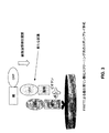
次に、蛍光蛋白質を付着させた直径30マイクロメートルの一組のキャリブレーションビーズを示す図7を参照して、実験例を説明する。蛍光蛋白質は、波長440ナノメートル(即ち、本例で利用するCFPドナーの蛍光吸収範囲内)のレーザ光により励起させ、図1の装置を使用して、ビーズからの蛍光を収集した。ビーズセットAは、CFPにより標識しており、青色及び黄色チャネルの両方に渡って広範な蛍光を示す。ビーズセットBは、YFPフルオロフォアにより標識しており、予想通りに黄色チャネルのみで蛍光を示す。ビーズセットCは、FRETペア(CFP−YFP)により標識しており、ドナーからアクセプタへのエネルギ移動のため、黄色チャネルでの蛍光の増大と、青色チャネルでの蛍光の減少とを示す。最後に、ビーズセットDは、ビーズセットA、B、及びCの混合物であり、青色及び黄色の両チャネルで蛍光を示す。 Next, an experimental example will be described with reference to FIG. 7 showing a set of calibration beads having a diameter of 30 micrometers to which a fluorescent protein is attached. The fluorescent protein was excited by a laser beam having a wavelength of 440 nanometers (that is, within the fluorescence absorption range of the CFP donor used in this example), and fluorescence from the beads was collected using the apparatus shown in FIG. Bead set A is labeled with CFP and exhibits extensive fluorescence across both the blue and yellow channels. Bead set B is labeled with a YFP fluorophore and shows fluorescence only in the yellow channel as expected. Bead set C is labeled with a FRET pair (CFP-YFP) and shows an increase in fluorescence in the yellow channel and a decrease in fluorescence in the blue channel due to energy transfer from the donor to the acceptor. Finally, bead set D is a mixture of bead sets A, B, and C, showing fluorescence in both the blue and yellow channels.
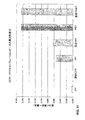
図8は、図7のキャリブレーションビーズの強度及び異方性散布プロットを示す。図8の左側のグラフで分かるように、測定黄色強度に対して測定青色強度をプロットする色比プロットでは、CFPビーズセットをFRETビーズセットから分離するのが容易である。図8の右側のグラフは、青色蛍光と黄色蛍光との異方性に関して対応するプロットを示している。異方性のプロットで分かるように、CFPビーズセットがFRETビーズセットから明確に区別されており、異方性がFRETの発生を測定するのに有効な特性であることが確認される。更に、図8の異方性プロットからは、黄色蛍光の異方性は、CFPビーズセットとFRETビーズセットとの間で変化するが、青色蛍光の異方性は、両方のケースで同じ状態を保つことが分かる。別の表現をすると、CFP及びFRETの異方性散布プロットは、水平方向(青色異方性)では基本的に同じ範囲に広がるが、図の垂直方向(黄色異方性)では異なる範囲に広がる。したがって、青色異方性は、黄色い方性の変化を測定するための内部基準として使用できる。上記の装置により二つの異方性を同時に測定できるため、黄色及び青色信号間で共通する何らかの局所的な未知の要素及びキャリブレーション係数が考慮され、これにより、FRET相互作用を測定するための改良された方法が生じる。 FIG. 8 shows a strength and anisotropic scatter plot of the calibration beads of FIG. As can be seen in the graph on the left side of FIG. 8, it is easy to separate the CFP bead set from the FRET bead set in a color ratio plot that plots the measured blue intensity against the measured yellow intensity. The graph on the right side of FIG. 8 shows a corresponding plot for the anisotropy of blue and yellow fluorescence. As can be seen from the anisotropy plot, the CFP bead set is clearly distinguished from the FRET bead set, confirming that anisotropy is an effective property for measuring the occurrence of FRET. Furthermore, from the anisotropy plot of FIG. 8, the yellow fluorescence anisotropy varies between the CFP and FRET bead sets, while the blue fluorescence anisotropy remains the same in both cases. I can keep it. In other words, the CFP and FRET anisotropy scatter plots basically span the same range in the horizontal direction (blue anisotropy), but spread in different ranges in the vertical direction of the figure (yellow anisotropy). . Therefore, the blue anisotropy can be used as an internal reference for measuring the change in yellowness. Since the above apparatus can measure two anisotropies simultaneously, it takes into account any local unknown factors and calibration factors that are common between the yellow and blue signals, thereby improving the FRET interaction The resulting method occurs.
図9及び10は、それぞれ図8の強度及び異方性散布プロットに対応する棒グラフを示す。図9において、左側の二本の棒は、図7のCFP及びFRETビーズセットで測定された黄色及び青色強度の比((黄色強度)/(青色強度))を示す。右側の二本の棒は、ビーズセットを同じウェル内に混合物として共に配置した時、即ち、「混合」した時に、強度比が基本的に同じ状態を維持することを示している。更に、両方のケースにおいて、FRET相互作用の発生がCFPによる非FRET蛍光から容易に識別されることが、図9から明らかとなる。図10は、キャリブレーションビーズのCFP及びYFPでの平均異方性を示している。左側の二本の棒は、青色及び黄色チャネルの両方において、CFP異方性が約0.3であり、この実験で提供した他の試料に比べて相対的に高いことを示している。黄色チャネルのYFP異方性は僅かに低く、これはYFPの低い「固有異方性」によるものと思われ、即ち、YFPが励起され蛍光を発するメカニズムのために、YFPは初期状態で低い異方性を有する可能性がある。 9 and 10 show bar graphs corresponding to the intensity and anisotropic scatter plots of FIG. 8, respectively. In FIG. 9, the two bars on the left indicate the ratio of yellow and blue intensity ((yellow intensity) / (blue intensity)) measured with the CFP and FRET bead set of FIG. The two bars on the right show that the intensity ratio remains essentially the same when the bead set is placed together as a mixture in the same well, ie when “mixed”. Furthermore, it is clear from FIG. 9 that in both cases the occurrence of FRET interactions is easily distinguished from non-FRET fluorescence by CFP. FIG. 10 shows the average anisotropy of the calibration beads at CFP and YFP. The two bars on the left indicate that the CFP anisotropy is about 0.3 in both the blue and yellow channels, which is relatively high compared to the other samples provided in this experiment. The yellow channel has a slightly lower YFP anisotropy, which may be due to the low “inherent anisotropy” of YFP, ie, due to the mechanism by which YFP is excited and fluoresces, There is a possibility of having a direction.
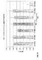
最も右側の二本の棒から分かるように、FRET信号は、青色異方性と黄色異方性との分離の著しい増加を示している。実際、青色異方性が非FRETの例と比べて増加する一方で、FRETの黄色異方性は減少している。FRET青色異方性の増加は、FRETによりCFPの蛍光継続時間が減少し、結果として、発光周波数の偏光状態にランダム性を持ち込む変化を受ける機会が僅かに減ったことに由来する可能性が高い。言い換えると、ドナーフルオロフォアからの発光は、本来は蛍光放射発光へ向かうはずの一部のエネルギがアクセプタフルオロフォアへ伝達されることで限定され、ドナーから放出された残りのエネルギは高い異方性を有する。FRET黄色は、CFPの直接励起(スペクトルの黄色端部におけるCFPによる発光の一部)と、YFPの直接励起(CFPを刺激するのに使用される放射による)と、FRETに由来するYFP発光との組み合わせである。異方性は、これらの成分のそれぞれについて異なるため、最も右側の棒が表すものは、こうした要素のそれぞれにおける異方性の加重平均となる。最初の二要素では、相対的に高い異方性が生じる。そうであっても、FRET黄色の平均異方性は、図10の他の平均異方性よりも大幅に低いため、FRET相互作用の良好なインジケータとなる。 As can be seen from the two bars on the rightmost side, the FRET signal shows a significant increase in the separation between blue and yellow anisotropy. In fact, the blue anisotropy increases compared to the non-FRET example, while the yellow anisotropy of FRET decreases. The increase in FRET blue anisotropy is likely due to a decrease in the CFP fluorescence duration due to FRET, resulting in a slight decrease in the chance of undergoing a change that introduces randomness into the polarization state of the emission frequency. . In other words, the emission from the donor fluorophore is limited by the transfer of some energy that would otherwise be directed to fluorescence emission to the acceptor fluorophore, and the remaining energy released from the donor is highly anisotropic. Have FRET yellow is the direct excitation of CFP (part of the emission by CFP at the yellow end of the spectrum), the direct excitation of YFP (due to the radiation used to stimulate CFP), and the YFP emission derived from FRET. It is a combination. Since anisotropy is different for each of these components, what the rightmost bar represents is a weighted average of the anisotropy in each of these elements. In the first two elements, a relatively high anisotropy occurs. Even so, the average anisotropy of FRET yellow is much lower than the other average anisotropies of FIG. 10, thus providing a good indicator of FRET interaction.
図11は、CFPビーズ、YFPビーズ、及びFRETビーズの分離及び混合セットの異方性の差を示す棒グラフである。図11から分かるように、黄色及び青色異方性の差は、ビーズを一度に一種類ずつ調べても、混合したビーズセットとして調べても、基本的に同じである。更に図11から分かるように、FRET相互作用の青色及び黄色異方性には、それぞれCFP及びYFPより遥かに大きい差が存在するため、FRET相互作用は、CFP及びYFPそれぞれから容易に分離できる。 FIG. 11 is a bar graph showing the difference in anisotropy of CFP, YFP, and FRET beads separation and mixing sets. As can be seen from FIG. 11, the difference in yellow and blue anisotropy is basically the same whether the beads are examined one type at a time or as a mixed bead set. Further, as can be seen from FIG. 11, the FRET interaction can be easily separated from CFP and YFP, respectively, because there is a much larger difference in the blue and yellow anisotropy of FRET interaction than CFP and YFP, respectively.
次に、CFP/YFPトランスフェクション生細胞において、どのようにFRETを特定できるかを示す例を提示する。図12は、mCer−N3、mVenus−C1、及びSCAT3.1(カスパーゼ−3活性に対するCFP/YFP FRETセンサ)によりトランスフェクトしたCos−7細胞の画像を示している。カスパーゼ活性は、細胞の一部の集団におけるアポトーシスのインジケータとして使用し得る。この例において、トランスフェクションは、96ウェルガラス底プレートで行っており、24時間に渡って細胞をトランスフェクトした。その後、細胞に波長440ナノメートル(CFPの蛍光刺激周波数)のレーザ光を照射し、図1で説明したシステムの一部の特徴を有する装置を使用して、細胞からの蛍光を収集した。図12に示したように、細胞AはCFP(Cerulean)によりトランスフェクトしており、細胞BはYFP(Venus)によりトランスフェクトしており、細胞CはCFP及びYFPによりコトランスフェクト、即ち、CFP及びYFPを別個に、FRETペアとしてではなく追加しており、最後に細胞Dは、相互作用する二種類の蛋白質により、それぞれが互いに40オングストローム以内の距離に位置して、FRET相互作用が発生可能となるようにトランスフェクトした。FRET技術は、生体内の内因性カスパーゼ活性の力学及びパターンについて有意義な情報を提供できる。強化シアン蛍光蛋白質(ECFP)を含む組み換えカスパーゼ基板をFRETドナーとして使用してよく、強化黄色蛍光蛋白質(EYFP)をFRETアクセプタとして、カスパーゼ−3切断配列(DEVD)を含むペプチドにより連結する。こうしたインジケータの開発により、研究者は、単一の細胞レベルにおいて、リアルタイムでのカスパーゼ活性のモニタが可能となる。図12において分かるように、様々な細胞グループの蛍光パターンは、図7に関して上述したキャリブレーションビーズのものに類似する。しかしながら、SCATセンサの場合には、カスパーゼが活性化するとFRETが消滅し、したがってアポトーシスの事象が検知される。SCAT3.1センサとして表現されるFRET相互作用及び信号は、ここではカスパーゼ−3の活性化及び切断の前に示される。 Next, an example is shown that shows how FRET can be identified in CFP / YFP transfected live cells. FIG. 12 shows an image of Cos-7 cells transfected with mCer-N3, mVenus-C1, and SCAT3.1 (CFP / YFP FRET sensor for caspase-3 activity). Caspase activity can be used as an indicator of apoptosis in some populations of cells. In this example, transfection was done in 96 well glass bottom plates and cells were transfected for 24 hours. Thereafter, the cells were irradiated with laser light having a wavelength of 440 nanometers (fluorescence stimulation frequency of CFP), and fluorescence from the cells was collected using an apparatus having some characteristics of the system described in FIG. As shown in FIG. 12, cell A is transfected with CFP (Cerulean), cell B is transfected with YFP (Venus), and cell C is co-transfected with CFP and YFP, ie, CFP. And YFP separately, not as a FRET pair, and finally cell D is located within 40 angstroms of each other due to the two interacting proteins, allowing FRET interactions to occur It was transfected so that. FRET technology can provide meaningful information about the dynamics and patterns of endogenous caspase activity in vivo. A recombinant caspase substrate containing an enhanced cyan fluorescent protein (ECFP) may be used as a FRET donor, and the enhanced yellow fluorescent protein (EYFP) is used as a FRET acceptor and linked by a peptide containing a caspase-3 cleavage sequence (DEVD). The development of such indicators allows researchers to monitor caspase activity in real time at the single cell level. As can be seen in FIG. 12, the fluorescence patterns of the various cell groups are similar to those of the calibration beads described above with respect to FIG. However, in the case of the SCAT sensor, when caspase is activated, FRET disappears and thus an apoptotic event is detected. FRET interactions and signals expressed as SCAT3.1 sensors are shown here prior to caspase-3 activation and cleavage.
図13は、図12の生細胞の強度及び異方性散布プロットを示す。図13で分かるように、図8のキャリブレーションビーズで得られたプロットと非常に似ている。特に、図13の右側の異方性散布プロットで分かるように、FRET異方性は、コトランスフェクション細胞とCFP細胞との両方から容易に分離できる。 FIG. 13 shows the intensity and anisotropic scatter plot of the live cells of FIG. As can be seen in FIG. 13, it is very similar to the plot obtained with the calibration beads of FIG. In particular, FRET anisotropy can be easily separated from both co-transfected cells and CFP cells, as can be seen in the anisotropic scatter plot on the right side of FIG.
図14は、図13のそれぞれの強度プロットに対応する棒グラフを示す。図10で分かるように、FRET細胞は、CFP及びコトランスフェクション細胞のそれぞれから容易に識別できる。 FIG. 14 shows a bar graph corresponding to each intensity plot of FIG. As can be seen in FIG. 10, FRET cells can be easily distinguished from each of CFP and co-transfected cells.
図15は、CFP/YFPトランスフェクション細胞の平均異方性を示している。ここでも、結果は、キャリブレーションビーズにより得られた、図10に図示したものに類似する。FRET黄色の平均異方性は、図11の他の平均異方性より大幅に低いため、FRET相互作用の良好なインジケータとなる。 FIG. 15 shows the average anisotropy of CFP / YFP transfected cells. Again, the results are similar to those shown in FIG. 10 obtained with calibration beads. The average anisotropy of FRET yellow is significantly lower than the other average anisotropies of FIG. 11, thus providing a good indicator of FRET interaction.
図16は、CFP細胞、YFP細胞、コトランスフェクション細胞、及びFRET細胞の青色及び黄色異方性の差を示す棒グラフである。図16から分かるように、FRET細胞の青色及び黄色異方性には、CFP細胞、YFP細胞、及びコトランスフェクション細胞のそれぞれよりも遥かに大きな差が存在するため、FRET細胞は、他の細胞からから容易に識別できる。 FIG. 16 is a bar graph showing the difference in blue and yellow anisotropy of CFP cells, YFP cells, co-transfected cells, and FRET cells. As can be seen from FIG. 16, the FRET cells have a much larger difference in blue and yellow anisotropy than CFP cells, YFP cells, and co-transfected cells, respectively. Can be easily identified from
次に、本発明の特定の処理実施形態のまとめを提示する。図17では、一部の実施形態において採用し得る動作の幾つかを示すフローチャートを提示している。フローチャートは連続する一連の動作として提示されているが、本発明は、提示した順序に限定されない。更に、説明したように、動作の一部は同時に実行し得る。他の動作は、示したものと逆の順序で実行し得る。 Next, a summary of specific processing embodiments of the present invention is presented. FIG. 17 presents a flowchart illustrating some of the operations that may be employed in some embodiments. Although the flowchart is presented as a continuous series of operations, the present invention is not limited to the presented order. Furthermore, as described, some of the operations can be performed simultaneously. Other operations may be performed in the reverse order as shown.
図17に示したプロセスでは、種A及びB間の相互作用に対してアッセイが実行されると仮定する。種A及び種Bは、ここでは第一及び第二の化学物質と呼ばれる場合がある。これらの用語は、様々な分子、分子断片、複合体、分子の集合、分子の超構造、細胞小器官を含む細胞成分等を広範に網羅するものとする。多くの生体分子は、化学物質として機能し得る。例には、核酸と、蛋白質及びペプチドと、脂質と、炭水化物と、その組み合わせとが含まれる。指摘したように、本発明の方法及び装置は、第一及び第二の化学物質間の相互作用における変化を測定し得る。こうした変化は、物質間の結合と、物質を含む構造の切断と、一方または両方の物質のコンホメーションの変化(例えば、蛋白質の折り畳み)と、一方または両方の物質の立体障害と、結合、コンホメーション等に影響を与え得る、物質の化学修飾(例えば、リン酸化)と、オリゴマ形成等により発生し得る。 In the process shown in FIG. 17, it is assumed that the assay is performed on the interaction between species A and B. Species A and B may be referred to herein as first and second chemicals. These terms are intended to broadly cover various molecules, molecular fragments, complexes, molecular assemblies, molecular superstructures, cellular components including organelles, and the like. Many biomolecules can function as chemicals. Examples include nucleic acids, proteins and peptides, lipids, carbohydrates, and combinations thereof. As indicated, the method and apparatus of the present invention can measure changes in the interaction between the first and second chemicals. These changes include binding between substances, cleavage of the structure containing the substance, conformational change of one or both substances (eg, protein folding), steric hindrance of one or both substances, binding, It can occur due to chemical modification (eg, phosphorylation) of the substance, oligomer formation, etc. that can affect conformation and the like.
図17の最上ブロック、動作1701に示したように、通常の試料に提供し得る成分には、種Aに関連するドナーフルオロフォアと、種Bに関連するアクセプタフルオロフォアとが含まれる。通常、必ずではないが、試料の成分は、一定期間に渡って(単一の溶液との接触等により)接触状態が維持される。反応の時間分解追跡が望ましい他の実施形態では、FRETについて試料を即座に調査してよい。図17では、ブロック1703が調査を示しており、アッセイを実行するシステムは、ドナーフルオロフォアの蛍光励起波長の範囲内の波長を有する励起放射を提供する。
As shown in the top block of FIG. 17,
プロセスの何れかの時点で、システムは、異方性の基準に関連する波長で偏光異方性の尺度を取得する。ブロック1705を参照されたい。これには、動作1703で付与したものとは異なる波長での励起放射を提供することが伴い得る。しかしながら、多くの実施形態では、単一の励起源、即ちドナーの励起周波数であるもので十分となる。ブロック1707に示したように、プロセスは、更に、アクセプタフルオロフォアがFRET中に放射を発する波長で偏光異方性の尺度を取得することを含む。この情報により、システムは、アクセプタの発光波長での異方性の尺度を、異方性基準の波長での異方性の尺度と比較する。ブロック1709を参照されたい。この異方性の比較に基づき、プロセスは、種Aと種Bとの間の反応または相互作用を評価する。ブロック1711を参照されたい。
At any point in the process, the system obtains a measure of polarization anisotropy at the wavelength associated with the anisotropy criterion. See
このブロック1701で述べた相互作用または反応は、通常、種A、種B、ドナーフルオロフォア、及びアクセプタフルオロフォアが混合その他の形で互いに密接に接触可能となる、小さな、場合によっては閉ざされた範囲等、指定された試料領域において行われる。通常、必ずではないが、試料領域は、マルチウェルプレート上のウェルまたはスポット領域、或いは、流路内の領域である。別の例には、(a)組織または器官試料、血流等の原位置分析と、(b)2005年2月9日提出の米国特許出願第11/055,244号(出典を明記することで実質上本願明細書の一部とする)において説明されるような平面回転基板と、(c)細胞、或いは核または細胞質等の細胞内の区画の原位置分析、及び(d)個別の領域または特定の集合体がFRET信号を発生させる特定の相互作用を起こしている可能性のある、細胞コロニ等の細胞の集合体の原位置分析とが含まれる。
The interactions or reactions described in this
上記のように、ドナー及びアクセプタフルオロフォアは、FRETペアを形成可能となるべきである。多数の適切なフルオロフォアペアが、当業者に知られている。上記の蛍光蛋白質ペアの例に加え、FRETペアへの関与に適した他の蛍光物質には、フルオレセインと、ローダミンと、Bodipyファミリの染料(カリフォルニア州カールズバッドのInvitrogen Corporationから入手可能)と、臭化エチジウムと、蛍光クマリンと、シアニン染料等が含まれる。様々な蛍光蛋白質(通常は、生体内でキメラ融合蛋白質として提供)を利用し得る。これらには、Discosomaサンゴからクロン形成した赤色蛍光蛋白質(DsRedまたはdrFP583)と、緑色蛍光蛋白質(GFP)と、GFPの青色、シアン、及び黄色のバリエーションと、シアン蛍光蛋白質と、黄色蛍光蛋白質とが、幾つかの例として含まれる。 As noted above, the donor and acceptor fluorophores should be able to form FRET pairs. A number of suitable fluorophore pairs are known to those skilled in the art. In addition to the fluorescent protein pair example above, other fluorescent materials suitable for participation in the FRET pair include fluorescein, rhodamine, and Bodipy family dyes (available from Invitrogen Corporation, Carlsbad, Calif.), Bromide. Ethidium, fluorescent coumarin, cyanine dye and the like are included. Various fluorescent proteins (usually provided as a chimeric fusion protein in vivo) can be utilized. These include red fluorescent protein (DsRed or drFP583) formed from Discosoma coral, green fluorescent protein (GFP), blue, cyan, and yellow variations of GFP, cyan fluorescent protein, and yellow fluorescent protein. Are included as examples.
最初にアッセイの成分を一緒にする時には、種A及びBは、物理的に分離していても、連結していてもかまわない。分離した種は、アッセイ試料内で結合または反応が生じるかを評価するために接触状態にさせる、結合または反応を起こすペアにしてよい。このような場合、アッセイは、アクセプタの発光周波数からの信号において、偏光異方性が相対的に高い状態で開始され得る。しかし、反応が生じた時、或いは生じた場合には、アクセプタの発光による偏光異方性において、検出可能な現象が生じる。別のケースにおいて、種A及びBが当初連結しており、その後、開裂その他の形で互いに更に分離した状態にする可能性のある条件に晒される場合には、検査中の反応または相互作用により、アクセプタの発光波長で収集した信号において、偏光異方性に検出可能な増加が生じる。 When the assay components are first brought together, species A and B can be physically separated or linked. The separated species may be a pair that undergoes binding or reaction that is brought into contact to assess whether binding or reaction occurs in the assay sample. In such cases, the assay can be initiated with a relatively high polarization anisotropy in the signal from the acceptor emission frequency. However, when or when the reaction occurs, a detectable phenomenon occurs in the polarization anisotropy due to the emission of the acceptor. In other cases, if species A and B are initially linked and then subjected to conditions that may be further separated from each other by cleavage or other, by reaction or interaction during the test. There is a detectable increase in polarization anisotropy in the signal collected at the emission wavelength of the acceptor.
動作1703に関して、本明細書で説明したアッセイ用の励起源には、通常、直線偏光、或いは強い偏光が施される。励起源は、ドナーフルオロフォアの励起周波数において、狭い周波数帯域で提供されるが、これは常に必要な訳ではなく、特に、アクセプタフルオロフォアの励起周波数と、ドナー及びアクセプタフルオロフォアの発光周波数とがアクセプタの励起周波数から十分に離れている場合には、その必要はない。励起放射の強度は、考慮中のアッセイの必要に応じて選択される。通常は、強いFRET信号を生成するのに十分な高さだが、種が起こしている反応に干渉するほど高くはない強度を提供することが望まれる。多くのin vitroアッセイでは、励起源の強度範囲(試料と相互作用する際のもの―レンズによる損失を考慮する)は、約1×10³乃至2×10⁵ワット/cm2である。更に一般的には、強度範囲は、約2×103乃至2×104ワット/cm2である。
With respect to
動作1705に関して、基準は、試料からの偏光異方性信号のキャリブレーションまたは比較のために提供される。上記のように、FRET相互作用以外のアッセイの局所的条件は、単独で異方性に影響を与え得る。結果として、異方性の絶対値ではなく、相対値を測定することが好ましい場合がある。基準からの偏光異方性の取得は、本明細書の別の部分で説明したように、即ち、基準信号が偏光された度合いを決定することで達成し得る。通常、これは、一方が励起源の提供する偏光方向に平行で、他方がその方向に垂直である二つの直交する偏光角度で信号を測定することにより求められる。二方向で得られた強度の大きな差が高い異方性を示すのに対し、二方向に渡って得られた、より等しい強度の値は、等方性を示す。ここでも、基準の異方性は、試料のアクセプタフルオロフォアの発光について測定した異方性をキャリブレーションする目的で取得される。
With respect to
上記のように、基準は、内部基準または外部基準にしてよい。内部基準信号は、通常、ドナーフルオロフォアの発光信号の異方性から求められる。外部基準は、ドナー蛍光発光以外のソースから得られる。上記のように、一例は、ドナーではなく、アクセプタでもない、試料内の基準フルオロフォアからの発光である。こうした基準は、試料格納容器での固定化、試料内のビーズへの提供、溶液中への提供等を行ってよい。外部基準の別の例は、使用中で測定される励起源からの放射であり、例えば、試料から収集された散乱光である。 As described above, the reference may be an internal reference or an external reference. The internal reference signal is usually obtained from the anisotropy of the emission signal of the donor fluorophore. The external reference is obtained from a source other than the donor fluorescence. As noted above, an example is light emission from a reference fluorophore in a sample that is neither a donor nor an acceptor. Such a standard may be fixed in a sample storage container, provided to beads in a sample, provided in a solution, or the like. Another example of an external reference is radiation from an excitation source that is measured in use, for example scattered light collected from a sample.
動作1707に関して、アクセプタフルオロフォア発光周波数の偏光異方性は、基準の変更異方性と同じ方法だが異なる波長で測定される。説明したように、検査中の相互作用が種A及びBを極めて近接した状態にするか、分離させるかに応じて、アクセプタの発光周波数での偏光異方性の減少または増加は、相互作用の形跡となる。
For
動作1709及び1711に関して、比較及び評価は、通常、コンピュータ、回路、または特別に構築された論理を使用して行われる。反応または相互作用が生じていることを示すために、試料及び基準間の異方性の差の閾値レベルを使用してよい。また、或いはこれに加えて、反応または相互作用が生じている範囲を示すために、異方性の差の定量値を使用してよい。特定の実施形態において、相対的な異方性の値は、種Aまたは種Bの濃度または効力の示度を提供する。
For
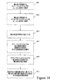
図18は、in vitroアッセイを実行するための一般的な一連の動作を表す別のフローチャートである。最初にブロック1801に示したように、種A及び関連するドナーフルオロフォアを、in vitro試料に提供する。ブロック1803に示したように、種B及び関連するアクセプタフルオロフォアも、in vitro試料に提供する。動作1801及び1803を合わせて、アッセイ試料を形成するために、二種類の溶液、即ち、種A及びそのフルオロフォアを含有するものと、種B及びそのフルオロフォアを含有する別のものとを混合することのみを含んでもよい点に留意されたい。しかしながら、特定の実施形態では、一方または両方のフルオロフォアを別の成分として追加するのが適切である。更に、種A及びBがカスパーゼ−3または他の生体分子のような連結構造を共に形成する場合、動作1801及び1803は、単一の動作として実行される。どのように実行されるかに関係なく、動作1801及び1803は、アッセイ試料を調製することを共に表す。高スループットシステムでは、多くの異なるアッセイ試料を迅速に連続して作成及び調査する。
FIG. 18 is another flow chart representing a general sequence of operations for performing an in vitro assay. Initially, as shown in
一部の実施形態では、FRET相互作用の検査前に、場合により所定の期間に渡って、或いは、上昇させた温度、低酸素等の特定の刺激に触れさせた後で、種とフルオロフォアとの相互作用を必要に応じて可能にする。ブロック1805を参照されたい。検査する試料は、調製後、ドナーフルオロフォアの蛍光励起波長の範囲内の波長を有する励起放射に露出することで調査する。ブロック1807を参照されたい。
In some embodiments, the species and fluorophore can be tested prior to testing for FRET interactions, optionally for a predetermined period of time, or after exposure to certain stimuli such as elevated temperature, hypoxia, etc. Allows for interaction as needed. See
アッセイ試料を励起放射に露出した後、システムは、アクセプタフルオロフォアの蛍光発光の波長での偏光異方性を測定する。ブロック1809を参照されたい。説明したように、この情報は、FRETが生じているかを判断するのに使用される。測定された偏光異方性に基づいて、プロセスでは、種A及び種B間で想定される反応または相互作用が生じたかを評価する。ブロック1811を参照されたい。反応が生じたと判断された場合、
本発明の一部の実施形態では、随意的に、反応が生じた度合いを判断する。
After exposing the assay sample to excitation radiation, the system measures the polarization anisotropy at the wavelength of the fluorescent emission of the acceptor fluorophore. See
In some embodiments of the invention, optionally, the degree to which a reaction has occurred is determined.
本発明の特定の実施形態は、上記の動作を実行するデバイス、システム、または装置に関する。システムは、必要な目的のために特別に構築してよく、或いは、例えば、コンピュータに格納されたコンピュータプログラムにより選択的に起動または構成される、汎用光学機器にしてもよい。上記のプロセスは、特定の光学機器またはコンピューティング装置に本質的に関連するものではない。 Certain embodiments of the invention relate to a device, system, or apparatus that performs the operations described above. The system may be specially constructed for the required purpose, or it may be a general purpose optical instrument that is selectively activated or configured, for example, by a computer program stored in the computer. The above process is not inherently related to a particular optical instrument or computing device.
以上、本発明の多数の実施例を説明してきたが、本発明の趣旨及び範囲から逸脱することなく、様々な変形を施し得ることは理解されよう。例えば、上記説明は、アッセイ用のスポットアレイ及び生細胞形式に重点を置いた。本発明は、もちろん、この形に限定されない。別の例として、固体基板はビーズを含んでもよい。スポットアレイ形式では、用途に応じて、様々な取り込み領域サイズを利用してよい。スポット密度も、用途に応じて変化する。特定の例では、基板は、ウェルを含み、例えば、約50nl以下のスポットサイズ等、用途の必要に応じたサイズとする。ウェルまたはスポットのパターンは、バーコード情報等の特定の情報を符号化または提供してよい。特定の応用において、基板は信号経路の中心要素に対して抗体アレイのパターンを提供するように設計される。スポットのパターンは、アッセイまたは信号読み出しの何れかに対する基準測定値または制御信号を生成するために使用される材料を含んでもよく、或いは、単純にアッセイスポットアレイの位置決めデバイス(基準)として使用してよい。したがって、添付特許請求の範囲には他の実施形態が含まれる。 While a number of embodiments of the invention have been described above, it will be understood that various modifications can be made without departing from the spirit and scope of the invention. For example, the above description has focused on assay spot arrays and live cell formats. Of course, the invention is not limited to this form. As another example, the solid substrate may include beads. In the spot array format, various capture area sizes may be used depending on the application. The spot density also varies depending on the application. In a particular example, the substrate includes wells and is sized according to the needs of the application, for example, a spot size of about 50 nl or less. The well or spot pattern may encode or provide specific information, such as barcode information. In certain applications, the substrate is designed to provide a pattern of antibody arrays to the central element of the signal path. The spot pattern may include material used to generate a reference measurement or control signal for either the assay or signal readout, or simply used as a positioning device (reference) for the assay spot array. Good. Accordingly, other embodiments are within the scope of the appended claims.
Claims (20)
ドナーフルオロフォアである第一のフルオロフォアに関連する前記第一の化学物質を固定化する工程と、
前記第二の化学物質を、前記固定化した第一の化学物質と結合可能にする工程であって、前記第二の化学物質は、前記第一のフルオロフォアとのFRETペアを形成する、アクセプタフルオロフォアである第二のフルオロフォアであるか、または、前記第二のフルオロフォアと結合した状態になる工程と、
前記結合化学物質を、前記第一または前記第二のフルオロフォアの何れかの励起周波数での放射に露出する工程と、
前記第一及び第二の化学物質間の特異結合を検出するために、前記ドナーフルオロフォア及び前記アクセプタフルオロフォアの発光波長におけるFRET蛍光信号の偏光異方性を測定する工程と、を備え、
前記ドナーフルオロフォアの発光波長での前記異方性を使用することは、前記アクセプタフルオロフォアの発光波長の前記異方性の変化を規定する内部基準の役割を果たす、
方法。A method for detecting specific binding between a first chemical substance and a second chemical substance, comprising:
Immobilizing said first chemical associated with a first fluorophore that is a donor fluorophore ;
An acceptor for allowing the second chemical substance to bind to the immobilized first chemical substance, wherein the second chemical substance forms a FRET pair with the first fluorophore. or a second fluorophore is a fluorophore, or a step of a state bound to the second fluorophore,
Exposing the binding chemical to radiation at an excitation frequency of either the first or the second fluorophore;
Measuring the polarization anisotropy of the FRET fluorescence signal at the emission wavelengths of the donor fluorophore and the acceptor fluorophore to detect specific binding between the first and second chemicals ,
Using the anisotropy at the emission wavelength of the donor fluorophore serves as an internal reference defining the change in the anisotropy of the emission wavelength of the acceptor fluorophore,
Method.
前記フルオロフォアの少なくとも一方を、前記ドナーフルオロフォアの励起波長での放射に露出する工程と、
蛍光信号の偏光異方性を、前記ドナーフルオロフォアの発光波長と、前記アクセプタフルオロフォアの発光波長とにおいて測定する工程と、
前記第一及び第二の化学物質間でFRET相互作用が発生しているかを判断するために、前記測定した異方性を比較する工程と、を備える方法。A method for detecting whether a FRET interaction has occurred between a first chemical associated with a donor fluorophore and a second chemical associated with an acceptor fluorophore, comprising:
Exposing at least one of the fluorophores to radiation at an excitation wavelength of the donor fluorophore;
Measuring the polarization anisotropy of the fluorescence signal at the emission wavelength of the donor fluorophore and the emission wavelength of the acceptor fluorophore;
Comparing the measured anisotropy to determine whether a FRET interaction has occurred between the first and second chemicals.
前記フルオロフォアを含有する領域を、前記ドナーフルオロフォアの励起波長での放射に露出する工程と、
蛍光信号の偏光異方性を、前記アクセプタフルオロフォアの発光波長において測定する工程と、
前記フルオロフォアを含有する前記領域における基準信号の波長において偏光異方性を測定する工程と、
前記第一及び第二の化学物質間でFRET相互作用が発生しているかを判断するために、前記測定した異方性を比較する工程と、を備える方法。A method for detecting whether a FRET interaction has occurred between a first chemical associated with a donor fluorophore and a second chemical associated with an acceptor fluorophore, comprising:
Exposing the region containing the fluorophore to radiation at the excitation wavelength of the donor fluorophore;
Measuring the polarization anisotropy of the fluorescent signal at the emission wavelength of the acceptor fluorophore;
Measuring polarization anisotropy at a wavelength of a reference signal in the region containing the fluorophore;
Comparing the measured anisotropy to determine whether a FRET interaction has occurred between the first and second chemicals.
Applications Claiming Priority (5)
| Application Number | Priority Date | Filing Date | Title |
|---|---|---|---|
| US66842805P | 2005-04-04 | 2005-04-04 | |
| US60/668,428 | 2005-04-04 | ||
| US67884205P | 2005-05-06 | 2005-05-06 | |
| US60/678,842 | 2005-05-06 | ||
| PCT/US2006/012292 WO2006107864A1 (en) | 2005-04-04 | 2006-04-03 | Screening using polarization anisotropy in fret emissions |
Publications (3)
| Publication Number | Publication Date |
|---|---|
| JP2008538004A JP2008538004A (en) | 2008-10-02 |
| JP2008538004A5 JP2008538004A5 (en) | 2009-05-21 |
| JP4921458B2 true JP4921458B2 (en) | 2012-04-25 |
Family
ID=37073796
Family Applications (1)
| Application Number | Title | Priority Date | Filing Date |
|---|---|---|---|
| JP2008505419A Expired - Fee Related JP4921458B2 (en) | 2005-04-04 | 2006-04-03 | Screening method using polarization anisotropy in FRET emission |
Country Status (5)
| Country | Link |
|---|---|
| US (2) | US20060234279A1 (en) |
| EP (1) | EP1866443A4 (en) |
| JP (1) | JP4921458B2 (en) |
| TW (1) | TW200704778A (en) |
| WO (1) | WO2006107864A1 (en) |
Families Citing this family (20)
| Publication number | Priority date | Publication date | Assignee | Title |
|---|---|---|---|---|
| WO2006107864A1 (en) * | 2005-04-04 | 2006-10-12 | Blueshift Biotechnologies, Inc. | Screening using polarization anisotropy in fret emissions |
| JP5189301B2 (en) * | 2007-03-12 | 2013-04-24 | オリンパス株式会社 | Laser scanning microscope |
| KR101679088B1 (en) | 2008-10-01 | 2016-12-06 | 셔윈 화 | System and method for wire-guided pedicle screw stabilization of spinal vertebrae |
| CN102448379B (en) | 2009-04-03 | 2014-11-19 | 米切尔·A·哈登布鲁克 | Surgical retractor system |
| CA2768330A1 (en) | 2009-07-28 | 2011-02-03 | F. Hoffmann-La Roche Ag | Non-invasive in vivo optical imaging method |
| KR101757319B1 (en) | 2010-03-26 | 2017-07-12 | 에코스타 테크놀로지스 엘엘씨 | Multiple input television receiver |
| CN102883670B (en) | 2010-03-30 | 2016-11-23 | S·华 | The system of pedicle screw and method for stable spinal column |
| US8569254B2 (en) | 2010-12-10 | 2013-10-29 | National Yang Ming University | Methods for modulating the expression and aggregation of CAG-expanded gene product in cells and methods for identifying agents useful for doing the same |
| WO2012119999A1 (en) | 2011-03-07 | 2012-09-13 | F. Hoffmann-La Roche Ag | Means and methods for in vivo testing of therapeutic antibodies |
| EP2683413A1 (en) | 2011-03-07 | 2014-01-15 | F.Hoffmann-La Roche Ag | In vivo selection of therapeutically active antibodies |
| KR101158362B1 (en) * | 2011-04-20 | 2012-06-22 | 한국과학기술원 | Method for analyzing single protein-protein interactions in whole cell lysates |
| EP2707714B1 (en) * | 2011-05-09 | 2019-10-09 | Whitehead Institute For Biomedical Research | Chaperone interaction assays and uses thereof |
| JP5877741B2 (en) * | 2012-03-16 | 2016-03-08 | 株式会社日立製作所 | Cell number monitoring method |
| WO2014059281A1 (en) * | 2012-10-11 | 2014-04-17 | The Regents Of The University Of Michigan | Fluorescence polarization assay for detecting high molecular weight molecules in biological fluids |
| CN102967554B (en) * | 2012-10-29 | 2016-12-21 | 广东工业大学 | A kind of dual pathways, the fluorescence anisotropy microscopic imaging device of monochromatic light line structure and method |
| EP3247990B1 (en) | 2015-01-23 | 2023-07-05 | Bayer Aktiengesellschaft | Method and device for determining the effect of active agents on nematodes and other organisms in aqueous assays |
| CN109509509B (en) * | 2018-09-29 | 2020-12-22 | 江西理工大学 | Protein compound mining method based on dynamic weighted protein interaction network |
| US11160580B2 (en) | 2019-04-24 | 2021-11-02 | Spine23 Inc. | Systems and methods for pedicle screw stabilization of spinal vertebrae |
| US11782001B2 (en) | 2020-12-04 | 2023-10-10 | Attolight AG | Dislocation type and density discrimination in semiconductor materials using cathodoluminescence measurements |
| TWI808554B (en) * | 2020-12-04 | 2023-07-11 | 亞光股份有限公司 | Dislocation type and density discrimination in semiconductor materials using cathodoluminescence measurements |
Family Cites Families (20)
| Publication number | Priority date | Publication date | Assignee | Title |
|---|---|---|---|---|
| US5524405A (en) | 1994-02-28 | 1996-06-11 | Byrd; Randall | Wall structure |
| US5807522A (en) * | 1994-06-17 | 1998-09-15 | The Board Of Trustees Of The Leland Stanford Junior University | Methods for fabricating microarrays of biological samples |
| US5597696A (en) * | 1994-07-18 | 1997-01-28 | Becton Dickinson And Company | Covalent cyanine dye oligonucleotide conjugates |
| US6573045B1 (en) * | 1998-06-05 | 2003-06-03 | Ribotargets, Ltd. | Methods and kits for discovery of RNA-binding compounds |
| EP1188057B1 (en) * | 1999-06-24 | 2008-01-23 | McMASTER UNIVERSITY | Incorporation and applications of biomolecular interactions within a carrier |
| US6509161B1 (en) * | 2000-02-29 | 2003-01-21 | Gentronix Limited | Green fluorescent protein |
| AU6152301A (en) * | 2000-05-12 | 2001-11-26 | Caliper Techn Corp | Detection of nucleic acid hybridization by fluorescence polarization |
| EP1409982A4 (en) * | 2001-06-14 | 2006-05-24 | Anadys Pharmaceuticals Inc | Methods of screening for ligands of target molecules |
| US20030228703A1 (en) | 2002-04-05 | 2003-12-11 | The Regents Of The University Of Michigan | Fluorescence resonance energy transfer quantitation and stoichiometry in living cells |
| US20030228603A1 (en) * | 2002-04-05 | 2003-12-11 | Cload Sharon T. | Compositions selective for caffeine or aspartame and methods of using same |
| US6713262B2 (en) * | 2002-06-25 | 2004-03-30 | Agilent Technologies, Inc. | Methods and compositions for high throughput identification of protein/nucleic acid binding pairs |
| JP2004093527A (en) * | 2002-09-04 | 2004-03-25 | Center For Advanced Science & Technology Incubation Ltd | Method of analyzing protein using fluorescence resonance energy transfer |
| JP4214206B2 (en) * | 2002-12-10 | 2009-01-28 | 独立行政法人理化学研究所 | Fluorescent indicator using FRET |
| JP2007504445A (en) | 2003-08-26 | 2007-03-01 | ブルーシフト・バイオテクノロジーズ・インコーポレーテッド | Time-dependent fluorescence measurement |
| US20050264805A1 (en) | 2004-02-09 | 2005-12-01 | Blueshift Biotechnologies, Inc. | Methods and apparatus for scanning small sample volumes |
| FR2872287B1 (en) * | 2004-06-28 | 2007-03-16 | Cis Bio Internat Sa | METHOD FOR IMPROVING THE DETECTION OF FLUORESCENCE SIGNALS DURING NON-RADIATIVE ENERGY TRANSFER |
| EP1774024A4 (en) * | 2004-07-02 | 2012-04-04 | Blueshift Biotechnologies Inc | Exploring fluorophore microenvironments |
| US8031338B2 (en) * | 2004-12-02 | 2011-10-04 | Vanderbilt University | Measuring Forster resonance energy transfer with polarized and depolarized light |
| WO2006107864A1 (en) * | 2005-04-04 | 2006-10-12 | Blueshift Biotechnologies, Inc. | Screening using polarization anisotropy in fret emissions |
| JP5189301B2 (en) * | 2007-03-12 | 2013-04-24 | オリンパス株式会社 | Laser scanning microscope |
-
2006
- 2006-04-03 WO PCT/US2006/012292 patent/WO2006107864A1/en active Application Filing
- 2006-04-03 JP JP2008505419A patent/JP4921458B2/en not_active Expired - Fee Related
- 2006-04-03 EP EP06758259A patent/EP1866443A4/en not_active Withdrawn
- 2006-04-04 TW TW095111992A patent/TW200704778A/en unknown
- 2006-04-04 US US11/398,496 patent/US20060234279A1/en not_active Abandoned
-
2008
- 2008-02-11 US US12/069,724 patent/US7674588B2/en not_active Expired - Fee Related
Also Published As
| Publication number | Publication date |
|---|---|
| US20060234279A1 (en) | 2006-10-19 |
| EP1866443A4 (en) | 2009-04-08 |
| US20080206888A1 (en) | 2008-08-28 |
| US7674588B2 (en) | 2010-03-09 |
| WO2006107864A1 (en) | 2006-10-12 |
| TW200704778A (en) | 2007-02-01 |
| EP1866443A1 (en) | 2007-12-19 |
| JP2008538004A (en) | 2008-10-02 |
Similar Documents
| Publication | Publication Date | Title |
|---|---|---|
| JP4921458B2 (en) | Screening method using polarization anisotropy in FRET emission | |
| US7141378B2 (en) | Exploring fluorophore microenvironments | |
| Piston et al. | Fluorescent protein FRET: the good, the bad and the ugly | |
| CN101432626B (en) | Highly sensitive system and methods for analysis of troponin | |
| JP3559525B2 (en) | Method of characterizing fluorescent molecules or other particles using generation functions | |
| JP2012514184A (en) | Methods for multi-analyte detection and quantification | |
| JP2010530069A (en) | Lattice-type sensor having both label detection-free binding detection function and fluorescence amplification function, and sensor reading system | |
| US20070254376A1 (en) | Method and apparatus for the detection of labeling elements in a sample | |
| US20210255195A1 (en) | High precision spectral fret assays | |
| US20120258553A1 (en) | Analyte measurement apparatus and method | |
| Tan et al. | Application of photonic crystal enhanced fluorescence to detection of low serum concentrations of human IgE antibodies specific for a purified cat allergen (Fel D1) | |
| JP5057377B2 (en) | Method and apparatus for measuring biological components or their functions | |
| JP2022172058A (en) | Highly sensitive system and method for analysis of troponin | |
| CN103353531A (en) | Highly sensitive system and methods for analysis of troponin | |
| WO2008080441A1 (en) | Micropatterning of biomolecules | |
| JP2010256010A (en) | Method of fluorometrically detecting antigen-antibody reaction | |
| Matthews et al. | A high-content screening platform utilizing polarization anisotropy and FLIM microscopy | |
| US20050124008A1 (en) | Homogeneous competition assays | |
| US20050191705A1 (en) | High throughput screening using fluorophore labeled lipid membranes and fluorescence correlation spectroscopy | |
| van Zanten et al. | Quantitative fluorescence emission anisotropy microscopy for implementing homo-FRET measurements in living cells | |
| EP3317643B1 (en) | Modulation of luminescent dyes | |
| WO2023057735A1 (en) | Apparatus and method for multi-characteristic measurement of radiation properties | |
| van Zanten et al. | Quantitative fluorescence emission anisotropy microscopy for implementing homo–fluorescence resonance energy transfer measurements in living cells | |
| CN115190969A (en) | Systems and methods for use in FRET microscopy | |
| Grigaravicius et al. | Protein Chip analysis by probing time-resolved UV-fluorescence |
Legal Events
| Date | Code | Title | Description |
|---|---|---|---|
| A521 | Request for written amendment filed |
Free format text: JAPANESE INTERMEDIATE CODE: A523 Effective date: 20090331 |
|
| A621 | Written request for application examination |
Free format text: JAPANESE INTERMEDIATE CODE: A621 Effective date: 20090331 |
|
| A977 | Report on retrieval |
Free format text: JAPANESE INTERMEDIATE CODE: A971007 Effective date: 20110530 |
|
| A131 | Notification of reasons for refusal |
Free format text: JAPANESE INTERMEDIATE CODE: A131 Effective date: 20110927 |
|
| A521 | Request for written amendment filed |
Free format text: JAPANESE INTERMEDIATE CODE: A523 Effective date: 20111220 |
|
| TRDD | Decision of grant or rejection written | ||
| A01 | Written decision to grant a patent or to grant a registration (utility model) |
Free format text: JAPANESE INTERMEDIATE CODE: A01 Effective date: 20120124 |
|
| A01 | Written decision to grant a patent or to grant a registration (utility model) |
Free format text: JAPANESE INTERMEDIATE CODE: A01 |
|
| A61 | First payment of annual fees (during grant procedure) |
Free format text: JAPANESE INTERMEDIATE CODE: A61 Effective date: 20120202 |
|
| R150 | Certificate of patent or registration of utility model |
Ref document number: 4921458 Country of ref document: JP Free format text: JAPANESE INTERMEDIATE CODE: R150 Free format text: JAPANESE INTERMEDIATE CODE: R150 |
|
| FPAY | Renewal fee payment (event date is renewal date of database) |
Free format text: PAYMENT UNTIL: 20150210 Year of fee payment: 3 |
|
| R250 | Receipt of annual fees |
Free format text: JAPANESE INTERMEDIATE CODE: R250 |
|
| R250 | Receipt of annual fees |
Free format text: JAPANESE INTERMEDIATE CODE: R250 |
|
| R250 | Receipt of annual fees |
Free format text: JAPANESE INTERMEDIATE CODE: R250 |
|
| R250 | Receipt of annual fees |
Free format text: JAPANESE INTERMEDIATE CODE: R250 |
|
| R250 | Receipt of annual fees |
Free format text: JAPANESE INTERMEDIATE CODE: R250 |
|
| R250 | Receipt of annual fees |
Free format text: JAPANESE INTERMEDIATE CODE: R250 |
|
| R250 | Receipt of annual fees |
Free format text: JAPANESE INTERMEDIATE CODE: R250 |
|
| LAPS | Cancellation because of no payment of annual fees |