JP4914143B2 - Optical equipment - Google Patents
Optical equipment Download PDFInfo
- Publication number
- JP4914143B2 JP4914143B2 JP2006214506A JP2006214506A JP4914143B2 JP 4914143 B2 JP4914143 B2 JP 4914143B2 JP 2006214506 A JP2006214506 A JP 2006214506A JP 2006214506 A JP2006214506 A JP 2006214506A JP 4914143 B2 JP4914143 B2 JP 4914143B2
- Authority
- JP
- Japan
- Prior art keywords
- detection sensor
- focus detection
- hood
- focus
- ring
- Prior art date
- Legal status (The legal status is an assumption and is not a legal conclusion. Google has not performed a legal analysis and makes no representation as to the accuracy of the status listed.)
- Expired - Fee Related
Links
Images

Classifications
-
- G—PHYSICS
- G02—OPTICS
- G02B—OPTICAL ELEMENTS, SYSTEMS OR APPARATUS
- G02B7/00—Mountings, adjusting means, or light-tight connections, for optical elements
- G02B7/02—Mountings, adjusting means, or light-tight connections, for optical elements for lenses
- G02B7/04—Mountings, adjusting means, or light-tight connections, for optical elements for lenses with mechanism for focusing or varying magnification
- G02B7/08—Mountings, adjusting means, or light-tight connections, for optical elements for lenses with mechanism for focusing or varying magnification adapted to co-operate with a remote control mechanism
Landscapes
- Physics & Mathematics (AREA)
- General Physics & Mathematics (AREA)
- Optics & Photonics (AREA)
- Automatic Focus Adjustment (AREA)
- Lens Barrels (AREA)
- Blocking Light For Cameras (AREA)
- Focusing (AREA)
Description
本発明は、デジタルカメラ、ビデオカメラ、デジタルスチルカメラ、テレビカメラ、交換レンズ、等の被写体に自動的に合焦するために焦点検出用センサを備えた光学機器に関するものである。 The present invention relates to an optical apparatus including a focus detection sensor for automatically focusing on a subject such as a digital camera, a video camera, a digital still camera, a television camera, and an interchangeable lens.
ビデオカメラやテレビカメラのオートフォーカス(TVAF)機能は、周知のようにCCD等の撮像装置の映像信号を、フォーカスレンズを微小量移動させながら取り込み、前後のコントラストによって合焦方向を判定するように構成されている。このようなTVAF方式では、光学素子が合焦付近にあるときは直ちに合焦状態になるが、ぼけが大きい場合には、フォーカスレンズを移動範囲内の端まで移動させてから合焦位置を探すことになり、映像が見苦しくなることがある。 As is well known, the autofocus (TVAF) function of a video camera or a television camera captures a video signal of an imaging device such as a CCD while moving the focus lens by a minute amount, and determines the in-focus direction based on the contrast before and after. It is configured. In such a TVAF system, when the optical element is near the focus, the focus state is immediately reached. However, when the blur is large, the focus lens is moved to the end within the moving range and then the focus position is searched. As a result, the video may become unsightly.
つまり、大きくピントがずれた状態ではコントラストが低すぎて合焦方向が判別できないため、フォーカスレンズを無限遠或いは至近端に移動させ、所定以上のコントラスト信号が得られる位置を探すという動作が必要になる。その間では、ピントが合わない画像が続くために、撮影者に不快感を与える。 In other words, when the focus is greatly out of focus, the contrast is too low to determine the in-focus direction. Therefore, it is necessary to move the focus lens to infinity or the close end to find a position where a contrast signal above a predetermined level can be obtained. become. In the meantime, since the image that is not in focus continues, the photographer feels uncomfortable.
一方で、デジタルスチルカメラでは、オートフォーカス機構としてセパレータレンズで分割した2つの像のずれを検出し、合焦方向とデフォーカス量を演算し、直ちに合焦状態にできるパッシブ方式を採用している。近年では、この合焦センサを汎用性を持たせたモジュール化とすることで、コンパクト化、低価格化、性能の安定化を実現している。 On the other hand, the digital still camera employs a passive system that detects the shift of two images divided by the separator lens as an autofocus mechanism, calculates the in-focus direction and the defocus amount, and can immediately bring it into focus. . In recent years, this focus sensor has been made into a module with versatility, thereby realizing compactness, low cost, and stable performance.
そこで、通常のオートフォーカスにはTVAFを使用しながらも、ぼけが大きい場合でも合焦位置に高速にフォーカスレンズを移動し、安価な焦点検出用センサモジュールを別個に設けたハイブリッド型のビデオカメラが提案されている。 Therefore, a hybrid video camera that uses TVAF for normal autofocus, moves the focus lens to the in-focus position at high speed even when blur is large, and separately provides an inexpensive focus detection sensor module. Proposed.
この焦点検出用センサモジュールの配置としては、特許文献1に記載されているように、レンズフードの内側に配置し、光学素子とセンサ測距域との視差をなくすように配置したものがある。 As the arrangement of the focus detection sensor module, as described in Patent Document 1, there is an arrangement in which the parallax between the optical element and the sensor ranging area is eliminated by disposing it inside the lens hood.
従来においては、焦点検出用センサモジュールをフード内に配置しているため、フード自体を光学機器に精度良く取り付けることが困難なため、撮影領域と測距領域を精度良く合せることができないという問題がある。また、フードを用いて着脱するために、焦点検出用センサと鏡筒間に電気接点を配置する必要があり、構造が複雑でAF機能の安定性を維持することが困難であるという問題もある。 Conventionally, since the focus detection sensor module is arranged in the hood, it is difficult to attach the hood itself to the optical device with high accuracy, and thus there is a problem in that the shooting area and the distance measurement area cannot be accurately combined. is there. In addition, in order to attach and detach using the hood, it is necessary to arrange an electrical contact between the focus detection sensor and the lens barrel, and there is a problem that the structure is complicated and it is difficult to maintain the stability of the AF function. .
本発明の目的は、上述の課題を解消し、より安定した構造で焦点検出用センサを配置し、高精度なオートフォーカスを実現し、操作リングの操作を阻害することのない光学機器を提供することにある。 An object of the present invention is to provide an optical device that solves the above-described problems, arranges a focus detection sensor with a more stable structure, realizes high-precision autofocus, and does not hinder the operation of the operation ring. There is.
上記目的を達成するために、本発明の光学機器は、光学素子と、前記光学素子を通過した撮影画像が入射する撮像素子と、前記光学素子を保持した鏡筒と、前記鏡筒の外周部に固定されたパッシブ方式の焦点検出用センサと、前記鏡筒の先端に配置されたフードと、フォーカス又はズームの手動調整を行うリング状操作部材と、前記鏡筒の外周部に配置されたグリップと、を備え、前記撮像素子からのコントラスト信号によってTVAFを行っている光学機器であって、
前記フードの外径は、前記鏡筒の外径より大きく、
前記焦点検出用センサは、前記フードの外周よりも前記光学素子の光軸側に位置し、前記フードは、前記焦点検出用センサに入射する光束を通過させるための開口部を前記フードの後方に有し、
前記開口部は、前記焦点検出用センサの前方に位置し、
前記焦点検出用センサは、前記リング状操作部材の外側において前記鏡筒の外周部に固定され、光軸方向から見て光軸に対して前記グリップと同じ方向に取り付けられていることを特徴とする。
In order to achieve the above object, an optical apparatus of the present invention includes an optical element, an imaging element on which a photographed image that has passed through the optical element is incident, a lens barrel that holds the optical element, and an outer peripheral portion of the lens barrel. A passive focus detection sensor fixed to the lens, a hood disposed at the tip of the lens barrel, a ring-shaped operation member for manually adjusting the focus or zoom, and a grip disposed on the outer periphery of the lens barrel And an optical device that performs TVAF using a contrast signal from the imaging device,
The outer diameter of the hood is larger than the outer diameter of the lens barrel,
The focus detection sensor is positioned on the optical axis side of the optical element with respect to the outer periphery of the hood, and the hood has an opening for allowing a light beam incident on the focus detection sensor to pass behind the hood. Have
The opening is located in front of the focus detection sensor ,
The focus detection sensor is fixed to the outer periphery of the barrel outside the ring-shaped operation member, and is attached to the optical axis in the same direction as the grip as viewed from the optical axis direction. To do.
本発明に係る光学機器によれば、フォーカス、ズーム等の手動リングを操作する際に、焦点検出用センサの突起が操作を妨げることを防止できる効果がある。 The optical device according to the present invention has an effect of preventing the protrusion of the focus detection sensor from interfering with the operation when operating a manual ring such as focus and zoom.
また、焦点検出用センサをフード内ではなく、光学素子に直接固定することにより、撮影画像と測距領域を精度良く位置合わせすることができ、オートフォーカスを高精度に行うことができる。 Further, by directly fixing the focus detection sensor to the optical element instead of in the hood, the captured image and the distance measurement area can be aligned with high accuracy, and autofocus can be performed with high accuracy.
更に、焦点検出用センサと光学素子の距離を短くできるため、撮影画像と測距範囲の視差を小さくできる利点がある。 Furthermore, since the distance between the focus detection sensor and the optical element can be shortened, there is an advantage that the parallax between the captured image and the distance measurement range can be reduced.
本発明を図示の実施例に基づいて詳細に説明する。
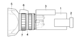
図1は光学機器であるビデオカメラの平面図であり、カメラ本体1の上部後方にファインダ2を有し、グリップ3は通常では右手でカメラ本体1を安定して保持できるようにファインダ2側から見て、カメラ本体1の右側に配置されている。カメラ本体1に固定され、光学素子を備えた撮影用の鏡筒4の先端には、フード5が取り付けられている。焦点検出用センサ6はリング状操作部材7の外側において鏡筒4の外周部に固定され、光軸方向から見てグリップ3と同じ方向に取り付けられており、レンズやカメラを主に操作する左手から遠い位置に配置されている。
The present invention will be described in detail based on the embodiments shown in the drawings.
FIG. 1 is a plan view of a video camera, which is an optical device, and has a
これにより、リング状操作部材7や、グリップ3上の各スイッチ類の操作の妨げにならないようにされている。
This prevents the ring-
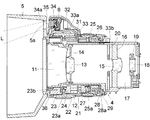
図2は鏡筒4の縦断面図、図3は焦点検出用センサ6の保持構造の分解斜視図である。鏡筒4には光学素子である複数のレンズが内蔵されており、固定の一群レンズである凸レンズ11は前固定筒12に固定され、変倍を行う第2群の凹レンズ13は2群鏡筒14に保持されている。この2群鏡筒14はズーミングの際に図示しないモータ等により光軸方向に移動するようにされている。凸の固定レンズ15は3群鏡筒16に保持され、3群鏡筒16は後固定筒17に固定されている。第4群の凸レンズ18は4群鏡筒19に保持され、図示しないモータ等により光軸方向に移動しフォーカス調節を行うようにされている。
FIG. 2 is a longitudinal sectional view of the
絞りユニット20は後固定筒17にビスにより固定され、後固定筒17の後方にはCCD等の図示しない撮像素子が取り付けられ、映像信号を取り出せるようにされている。また、後固定筒17の外周には、カメラ本体1に鏡筒4の全体を固定するための座4aが設けられている。
The
前固定筒12の外周には外側固定筒21が固定され、外側固定筒21の前方には、手動フォーカスを行うMFリング22が外側固定筒21に固定されたMFリング押え環23によって挟持され、定位置で回転自在に保持されている。MFリング22の内周に配置されたギア23aにエンコーダ24が係合され、MFリング22の回転角をパルス信号として検出できるようにされている。
An outer fixed
外側固定筒21の後方には、手動ズームを行うMZリング25が、外側固定筒21に固定されたMZリング押え環26によって挟持され、定位置で回転自在に保持されている。エンコーダ24と同様なエンコーダ27が、MZリング25の内周に配置したギア25aと係合され、MZリング25の回転角をパルス信号として検出できるようにされている。
Behind the outer fixed
更に、MZリング押え環26の後方には、手動で絞り調節を行う絞りリング28が、絞りリング押え環29によって定位置で回転自在に保持されている。絞りリング28には櫛歯状の凹凸28aが形成されており、凹凸を図示しないインタラプタにより検出することで、絞りリング28の回転角を検出するようにされている。エンコーダ24、27及びインタラプタは図示しないフレキシブルプリント基板によって配線され、カメラ本体1に設置された制御回路に電気的に接続されている。
Further, behind the MZ
MFリング22の一部を覆うようにセンサ保持台31が配置され、MFリング押え環23と外側固定筒21にビス31aによって固定され、焦点検出用センサ6を保持している。焦点検出用センサ6は像を2分割するセパレータレンズ、コントラストを検出するラインセンサ、信号処理回路を一体化したパッシブ方式による焦点検出用センサユニットにより構成されている。この焦点検出用センサユニットの構成は周知であり、例えば特許文献2に開示されている。
A
焦点検出用センサ6はセンサ保持台31の凹部31b内に保持され、レンズの撮影範囲と、焦点検出用センサ6の測距領域が一致するように、工具によってあおり調整がなされ、紫外線硬化接着剤等によって固定されている。本実施例のレンズはズームレンズであるため、望遠端の撮影領域の特定の被写体距離において、その中心に焦点検出用センサ6の測距領域が至るように調整されている。その際の被写体距離は、至近から無限遠の撮影可能領域において、測距領域が撮影画像から外れないように設定されている。
The
焦点距離の長い光学素子ほど撮影範囲が小さくなるため、焦点検出用センサ6の取り付けには高精度が要求され、そのための調整は必須であり、光学素子に近い位置に焦点検出用センサ6を取り付けるようにされている。
Since the photographing range becomes smaller as the optical element has a longer focal length, the
焦点検出用センサ6の信号を伝達するフレキシブルプリント基板32は、鏡筒4から突出したフレキシブルプリント基板33にコネクタ33aを介して接続されている。そして、レンズ後方に伸びた接点部33bから、カメラ本体1内の制御回路にAF信号を伝達するようにされている。
The flexible printed
焦点検出用センサ6を覆うセンサカバー34の前方には、焦点検出用センサ6に光線を入射させるためのカバーガラス35を備えた開口部34aが設けられ、センサカバー34は保持台31にビス34bによって固定されている。
In front of the
鏡筒4の先端に着脱可能に取り付けられたフード5は、MFリング押え環23にビス23bによって固定されたフロントリング36に、バヨネット方式により着脱自在に固定されている。焦点検出用センサ6はフード5の外周よりも光学素子であるレンズ11、12の光軸側に位置している。
The
フード5の奥部には、焦点検出用センサ6に入射する光束Lを妨げないような開口部5aが設けられている。そのため、焦点検出用センサ6を光学素子の光軸に近い位置に配置することができ、撮影画像と焦点検出用センサ6の測距位置との視差を少なくすることができる。
An
本実施例のビデオカメラは、撮像素子からのコントラスト信号によって、TVAFを行うように構成されており、その点において周知技術と何ら変りはない。しかし、従来のTVAFではフォーカスレンズをウォブリングにより微小振動させながらコントラスト信号の強弱を判定し、合焦させるためのフォーカスレンズの移動方向を判別している。このため、大きくピントがずれた状態では前述したような不具合が生ずることがある。 The video camera of the present embodiment is configured to perform TVAF based on a contrast signal from the image sensor, and there is no change from known technology in that respect. However, in the conventional TVAF, the strength of the contrast signal is determined while finely vibrating the focus lens by wobbling, and the moving direction of the focus lens for focusing is determined. For this reason, the above-described problems may occur when the focus is greatly deviated.
本実施例の焦点検出用センサ6は、このような不具合を防止するために、補助的に備えられている。焦点検出用センサ6はパッシブ方式のためピントが大きくずれた場合でも、合焦方向とずれ量が瞬時に演算されるため、フォーカスレンズを合焦位置に迅速に移動させることが可能になる。従って、焦点検出用センサ6によって迅速に合焦付近にフォーカスレンズを移動させ、画像信号によるTVAFによって高精度な合焦状態を維持することにより、オートフォーカスの高速化を図り、撮影者の不快感を解消できる。
The
このように、焦点検出用センサ6を鏡筒4の外周で、かつカメラグリップ3側の光学素子に近い位置に配置することにより、撮影画像とセンサ測距領域の位置合わせを高精度に行うことができ、手動調整を行う際の手動リングの操作を阻害することはない。また、フード5に焦点検出用センサ6用の開口部5aを設けることにより、焦点検出用センサ6を光学素子の光軸に近い位置に配置でき、視差を小さく抑えることができる。
In this way, by positioning the
以上の説明では、本発明の好ましい実施例について説明したが、本発明はこれらの実施例に限定されないことは云うまでもなく、その要旨の範囲内で種々の変形及び変更が可能である。 Although the preferred embodiments of the present invention have been described above, the present invention is not limited to these embodiments, and various modifications and changes can be made within the scope of the gist thereof.
1 カメラ本体
2 ファインダ
3 グリップ
4 鏡筒
5 フード
5a 開口部
6 焦点検出用センサ
7 リング状操作部材
22 MFリング
24、27 エンコーダ
25 MZリング
28 絞りリング
31 センサ保持台
34 センサカバー
DESCRIPTION OF SYMBOLS 1 Camera
Claims (2)
前記フードの外径は、前記鏡筒の外径より大きく、
前記焦点検出用センサは、前記フードの外周よりも前記光学素子の光軸側に位置し、前記フードは、前記焦点検出用センサに入射する光束を通過させるための開口部を前記フードの後方に有し、
前記開口部は、前記焦点検出用センサの前方に位置し、
前記焦点検出用センサは、前記リング状操作部材の外側において前記鏡筒の外周部に固定され、光軸方向から見て光軸に対して前記グリップと同じ方向に取り付けられていることを特徴とする光学機器。 An optical element; an imaging element on which a photographed image that has passed through the optical element is incident; a barrel that holds the optical element; a passive focus detection sensor that is fixed to an outer periphery of the barrel; and the mirror A hood disposed at the tip of the tube, a ring-shaped operation member that performs manual adjustment of focus or zoom, and a grip disposed on the outer periphery of the lens barrel, and TVAF is performed by a contrast signal from the imaging device An optical instrument,
The outer diameter of the hood is larger than the outer diameter of the lens barrel,
The focus detection sensor is positioned on the optical axis side of the optical element with respect to the outer periphery of the hood, and the hood has an opening for allowing a light beam incident on the focus detection sensor to pass behind the hood. Have
The opening is located in front of the focus detection sensor ,
The focus detection sensor is fixed to the outer periphery of the barrel outside the ring-shaped operation member, and is attached to the optical axis in the same direction as the grip as viewed from the optical axis direction. Optical equipment.
Priority Applications (3)
| Application Number | Priority Date | Filing Date | Title |
|---|---|---|---|
| JP2006214506A JP4914143B2 (en) | 2006-08-07 | 2006-08-07 | Optical equipment |
| US11/834,571 US7394604B2 (en) | 2006-08-07 | 2007-08-06 | Optical apparatus |
| CN200710143270A CN100580496C (en) | 2006-08-07 | 2007-08-07 | Optical apparatus |
Applications Claiming Priority (1)
| Application Number | Priority Date | Filing Date | Title |
|---|---|---|---|
| JP2006214506A JP4914143B2 (en) | 2006-08-07 | 2006-08-07 | Optical equipment |
Publications (3)
| Publication Number | Publication Date |
|---|---|
| JP2008040146A JP2008040146A (en) | 2008-02-21 |
| JP2008040146A5 JP2008040146A5 (en) | 2009-09-17 |
| JP4914143B2 true JP4914143B2 (en) | 2012-04-11 |
Family
ID=39028885
Family Applications (1)
| Application Number | Title | Priority Date | Filing Date |
|---|---|---|---|
| JP2006214506A Expired - Fee Related JP4914143B2 (en) | 2006-08-07 | 2006-08-07 | Optical equipment |
Country Status (3)
| Country | Link |
|---|---|
| US (1) | US7394604B2 (en) |
| JP (1) | JP4914143B2 (en) |
| CN (1) | CN100580496C (en) |
Families Citing this family (6)
| Publication number | Priority date | Publication date | Assignee | Title |
|---|---|---|---|---|
| WO2009141988A1 (en) * | 2008-05-19 | 2009-11-26 | Canon Kabushikikaisha | Image pickup system and lens apparatus |
| JP5553490B2 (en) * | 2008-06-17 | 2014-07-16 | キヤノン株式会社 | Imaging device |
| JP5430386B2 (en) * | 2009-12-22 | 2014-02-26 | キヤノン株式会社 | Imaging device |
| JP6204761B2 (en) * | 2013-09-03 | 2017-09-27 | キヤノン株式会社 | Lens apparatus and imaging apparatus having the same |
| JP6272090B2 (en) * | 2014-03-07 | 2018-01-31 | キヤノン株式会社 | Lens hood and imaging device |
| CN104238240A (en) * | 2014-09-10 | 2014-12-24 | 宗鸿电子科技(昆山)有限公司 | Lens |
Family Cites Families (7)
| Publication number | Priority date | Publication date | Assignee | Title |
|---|---|---|---|---|
| JPS57212421A (en) * | 1981-06-24 | 1982-12-27 | Nippon Kogaku Kk <Nikon> | Automatic focus detecting zoom lens |
| JPS6234135A (en) * | 1985-08-08 | 1987-02-14 | Canon Inc | Af device for variable focus camera |
| JPH0427414U (en) * | 1990-06-27 | 1992-03-04 | ||
| JPH08146287A (en) * | 1994-11-17 | 1996-06-07 | Canon Inc | Distance measuring device |
| US6456796B1 (en) * | 1999-03-02 | 2002-09-24 | Fuji Photo Optical Co., Ltd. | Manual and electric motor operated apparatus for lens barrels |
| JP2006119222A (en) * | 2004-10-19 | 2006-05-11 | Canon Inc | Imaging apparatus and method |
| JP2007078908A (en) * | 2005-09-13 | 2007-03-29 | Canon Inc | Lens device and its focusing control method |
-
2006
- 2006-08-07 JP JP2006214506A patent/JP4914143B2/en not_active Expired - Fee Related
-
2007
- 2007-08-06 US US11/834,571 patent/US7394604B2/en not_active Expired - Fee Related
- 2007-08-07 CN CN200710143270A patent/CN100580496C/en not_active Expired - Fee Related
Also Published As
| Publication number | Publication date |
|---|---|
| US7394604B2 (en) | 2008-07-01 |
| JP2008040146A (en) | 2008-02-21 |
| US20080030881A1 (en) | 2008-02-07 |
| CN101122668A (en) | 2008-02-13 |
| CN100580496C (en) | 2010-01-13 |
Similar Documents
| Publication | Publication Date | Title |
|---|---|---|
| KR101369666B1 (en) | Lens device and imaging device | |
| KR101395015B1 (en) | Camera, focus detection method and control method | |
| JP6415102B2 (en) | Lens barrel and optical apparatus having the same | |
| US10139587B2 (en) | Lens barrel and optical apparatus | |
| JP2007078833A (en) | Zoom lens and imaging apparatus having the same | |
| JP4914143B2 (en) | Optical equipment | |
| US8320755B2 (en) | Autofocusing zoom lens | |
| JP2006047723A (en) | Lens device and image pickup device | |
| JP2011039107A (en) | Optical apparatus | |
| JP5025527B2 (en) | Imaging device | |
| CN114839738A (en) | Lens apparatus, image pickup apparatus, and image pickup system | |
| JP2012159787A (en) | Focus detector, focus adjustment device and imaging apparatus | |
| JPH09184952A (en) | Lens barrel and optical equipment | |
| JPH09274130A (en) | Lens barrel and camera | |
| JP7433948B2 (en) | optical equipment | |
| JP6278735B2 (en) | Eccentricity adjusting device, optical apparatus, and eccentricity adjusting method | |
| WO2023204100A1 (en) | Optical device | |
| JP6051473B2 (en) | Zoom lens barrel | |
| US20230016323A1 (en) | Optical apparatus and camera system | |
| JP4612910B2 (en) | LENS DEVICE AND IMAGING DEVICE | |
| JP2014186285A (en) | Lens barrel and optical apparatus using the same | |
| JP2007240566A (en) | Focus detecting device, optical apparatus and camera | |
| JP2012154997A (en) | Lens barrel and image pickup apparatus including the same | |
| JP2023120477A (en) | Lens barrel, lens device, and imaging apparatus | |
| JP2016114847A (en) | Lens barrel, and optical device and imaging device using the same |
Legal Events
| Date | Code | Title | Description |
|---|---|---|---|
| A521 | Written amendment |
Free format text: JAPANESE INTERMEDIATE CODE: A523 Effective date: 20090803 |
|
| A621 | Written request for application examination |
Free format text: JAPANESE INTERMEDIATE CODE: A621 Effective date: 20090803 |
|
| RD01 | Notification of change of attorney |
Free format text: JAPANESE INTERMEDIATE CODE: A7421 Effective date: 20100218 |
|
| RD01 | Notification of change of attorney |
Free format text: JAPANESE INTERMEDIATE CODE: A7421 Effective date: 20100630 |
|
| A131 | Notification of reasons for refusal |
Free format text: JAPANESE INTERMEDIATE CODE: A131 Effective date: 20110322 |
|
| A521 | Written amendment |
Free format text: JAPANESE INTERMEDIATE CODE: A523 Effective date: 20110512 |
|
| A131 | Notification of reasons for refusal |
Free format text: JAPANESE INTERMEDIATE CODE: A131 Effective date: 20110719 |
|
| A521 | Written amendment |
Free format text: JAPANESE INTERMEDIATE CODE: A523 Effective date: 20110901 |
|
| TRDD | Decision of grant or rejection written | ||
| A01 | Written decision to grant a patent or to grant a registration (utility model) |
Free format text: JAPANESE INTERMEDIATE CODE: A01 Effective date: 20120117 |
|
| A01 | Written decision to grant a patent or to grant a registration (utility model) |
Free format text: JAPANESE INTERMEDIATE CODE: A01 |
|
| A61 | First payment of annual fees (during grant procedure) |
Free format text: JAPANESE INTERMEDIATE CODE: A61 Effective date: 20120120 |
|
| R151 | Written notification of patent or utility model registration |
Ref document number: 4914143 Country of ref document: JP Free format text: JAPANESE INTERMEDIATE CODE: R151 |
|
| FPAY | Renewal fee payment (event date is renewal date of database) |
Free format text: PAYMENT UNTIL: 20150127 Year of fee payment: 3 |
|
| LAPS | Cancellation because of no payment of annual fees |