JP4910482B2 - Variable valve operating device, control method thereof, and vehicle equipped with the same - Google Patents
Variable valve operating device, control method thereof, and vehicle equipped with the same Download PDFInfo
- Publication number
- JP4910482B2 JP4910482B2 JP2006145786A JP2006145786A JP4910482B2 JP 4910482 B2 JP4910482 B2 JP 4910482B2 JP 2006145786 A JP2006145786 A JP 2006145786A JP 2006145786 A JP2006145786 A JP 2006145786A JP 4910482 B2 JP4910482 B2 JP 4910482B2
- Authority
- JP
- Japan
- Prior art keywords
- motor
- path
- valve
- valve operating
- engine
- Prior art date
- Legal status (The legal status is an assumption and is not a legal conclusion. Google has not performed a legal analysis and makes no representation as to the accuracy of the status listed.)
- Active
Links
Images


Classifications
-
- B—PERFORMING OPERATIONS; TRANSPORTING
- B60—VEHICLES IN GENERAL
- B60W—CONJOINT CONTROL OF VEHICLE SUB-UNITS OF DIFFERENT TYPE OR DIFFERENT FUNCTION; CONTROL SYSTEMS SPECIALLY ADAPTED FOR HYBRID VEHICLES; ROAD VEHICLE DRIVE CONTROL SYSTEMS FOR PURPOSES NOT RELATED TO THE CONTROL OF A PARTICULAR SUB-UNIT
- B60W20/00—Control systems specially adapted for hybrid vehicles
-
- B—PERFORMING OPERATIONS; TRANSPORTING
- B60—VEHICLES IN GENERAL
- B60K—ARRANGEMENT OR MOUNTING OF PROPULSION UNITS OR OF TRANSMISSIONS IN VEHICLES; ARRANGEMENT OR MOUNTING OF PLURAL DIVERSE PRIME-MOVERS IN VEHICLES; AUXILIARY DRIVES FOR VEHICLES; INSTRUMENTATION OR DASHBOARDS FOR VEHICLES; ARRANGEMENTS IN CONNECTION WITH COOLING, AIR INTAKE, GAS EXHAUST OR FUEL SUPPLY OF PROPULSION UNITS IN VEHICLES
- B60K6/00—Arrangement or mounting of plural diverse prime-movers for mutual or common propulsion, e.g. hybrid propulsion systems comprising electric motors and internal combustion engines ; Control systems therefor, i.e. systems controlling two or more prime movers, or controlling one of these prime movers and any of the transmission, drive or drive units Informative references: mechanical gearings with secondary electric drive F16H3/72; arrangements for handling mechanical energy structurally associated with the dynamo-electric machine H02K7/00; machines comprising structurally interrelated motor and generator parts H02K51/00; dynamo-electric machines not otherwise provided for in H02K see H02K99/00
- B60K6/20—Arrangement or mounting of plural diverse prime-movers for mutual or common propulsion, e.g. hybrid propulsion systems comprising electric motors and internal combustion engines ; Control systems therefor, i.e. systems controlling two or more prime movers, or controlling one of these prime movers and any of the transmission, drive or drive units Informative references: mechanical gearings with secondary electric drive F16H3/72; arrangements for handling mechanical energy structurally associated with the dynamo-electric machine H02K7/00; machines comprising structurally interrelated motor and generator parts H02K51/00; dynamo-electric machines not otherwise provided for in H02K see H02K99/00 the prime-movers consisting of electric motors and internal combustion engines, e.g. HEVs
- B60K6/42—Arrangement or mounting of plural diverse prime-movers for mutual or common propulsion, e.g. hybrid propulsion systems comprising electric motors and internal combustion engines ; Control systems therefor, i.e. systems controlling two or more prime movers, or controlling one of these prime movers and any of the transmission, drive or drive units Informative references: mechanical gearings with secondary electric drive F16H3/72; arrangements for handling mechanical energy structurally associated with the dynamo-electric machine H02K7/00; machines comprising structurally interrelated motor and generator parts H02K51/00; dynamo-electric machines not otherwise provided for in H02K see H02K99/00 the prime-movers consisting of electric motors and internal combustion engines, e.g. HEVs characterised by the architecture of the hybrid electric vehicle
- B60K6/44—Series-parallel type
- B60K6/445—Differential gearing distribution type
-
- B—PERFORMING OPERATIONS; TRANSPORTING
- B60—VEHICLES IN GENERAL
- B60L—PROPULSION OF ELECTRICALLY-PROPELLED VEHICLES; SUPPLYING ELECTRIC POWER FOR AUXILIARY EQUIPMENT OF ELECTRICALLY-PROPELLED VEHICLES; ELECTRODYNAMIC BRAKE SYSTEMS FOR VEHICLES IN GENERAL; MAGNETIC SUSPENSION OR LEVITATION FOR VEHICLES; MONITORING OPERATING VARIABLES OF ELECTRICALLY-PROPELLED VEHICLES; ELECTRIC SAFETY DEVICES FOR ELECTRICALLY-PROPELLED VEHICLES
- B60L1/00—Supplying electric power to auxiliary equipment of vehicles
- B60L1/003—Supplying electric power to auxiliary equipment of vehicles to auxiliary motors, e.g. for pumps, compressors
-
- B—PERFORMING OPERATIONS; TRANSPORTING
- B60—VEHICLES IN GENERAL
- B60L—PROPULSION OF ELECTRICALLY-PROPELLED VEHICLES; SUPPLYING ELECTRIC POWER FOR AUXILIARY EQUIPMENT OF ELECTRICALLY-PROPELLED VEHICLES; ELECTRODYNAMIC BRAKE SYSTEMS FOR VEHICLES IN GENERAL; MAGNETIC SUSPENSION OR LEVITATION FOR VEHICLES; MONITORING OPERATING VARIABLES OF ELECTRICALLY-PROPELLED VEHICLES; ELECTRIC SAFETY DEVICES FOR ELECTRICALLY-PROPELLED VEHICLES
- B60L15/00—Methods, circuits, or devices for controlling the traction-motor speed of electrically-propelled vehicles
- B60L15/20—Methods, circuits, or devices for controlling the traction-motor speed of electrically-propelled vehicles for control of the vehicle or its driving motor to achieve a desired performance, e.g. speed, torque, programmed variation of speed
-
- B—PERFORMING OPERATIONS; TRANSPORTING
- B60—VEHICLES IN GENERAL
- B60L—PROPULSION OF ELECTRICALLY-PROPELLED VEHICLES; SUPPLYING ELECTRIC POWER FOR AUXILIARY EQUIPMENT OF ELECTRICALLY-PROPELLED VEHICLES; ELECTRODYNAMIC BRAKE SYSTEMS FOR VEHICLES IN GENERAL; MAGNETIC SUSPENSION OR LEVITATION FOR VEHICLES; MONITORING OPERATING VARIABLES OF ELECTRICALLY-PROPELLED VEHICLES; ELECTRIC SAFETY DEVICES FOR ELECTRICALLY-PROPELLED VEHICLES
- B60L3/00—Electric devices on electrically-propelled vehicles for safety purposes; Monitoring operating variables, e.g. speed, deceleration or energy consumption
- B60L3/0023—Detecting, eliminating, remedying or compensating for drive train abnormalities, e.g. failures within the drive train
-
- B—PERFORMING OPERATIONS; TRANSPORTING
- B60—VEHICLES IN GENERAL
- B60L—PROPULSION OF ELECTRICALLY-PROPELLED VEHICLES; SUPPLYING ELECTRIC POWER FOR AUXILIARY EQUIPMENT OF ELECTRICALLY-PROPELLED VEHICLES; ELECTRODYNAMIC BRAKE SYSTEMS FOR VEHICLES IN GENERAL; MAGNETIC SUSPENSION OR LEVITATION FOR VEHICLES; MONITORING OPERATING VARIABLES OF ELECTRICALLY-PROPELLED VEHICLES; ELECTRIC SAFETY DEVICES FOR ELECTRICALLY-PROPELLED VEHICLES
- B60L50/00—Electric propulsion with power supplied within the vehicle
- B60L50/10—Electric propulsion with power supplied within the vehicle using propulsion power supplied by engine-driven generators, e.g. generators driven by combustion engines
- B60L50/16—Electric propulsion with power supplied within the vehicle using propulsion power supplied by engine-driven generators, e.g. generators driven by combustion engines with provision for separate direct mechanical propulsion
-
- B—PERFORMING OPERATIONS; TRANSPORTING
- B60—VEHICLES IN GENERAL
- B60L—PROPULSION OF ELECTRICALLY-PROPELLED VEHICLES; SUPPLYING ELECTRIC POWER FOR AUXILIARY EQUIPMENT OF ELECTRICALLY-PROPELLED VEHICLES; ELECTRODYNAMIC BRAKE SYSTEMS FOR VEHICLES IN GENERAL; MAGNETIC SUSPENSION OR LEVITATION FOR VEHICLES; MONITORING OPERATING VARIABLES OF ELECTRICALLY-PROPELLED VEHICLES; ELECTRIC SAFETY DEVICES FOR ELECTRICALLY-PROPELLED VEHICLES
- B60L50/00—Electric propulsion with power supplied within the vehicle
- B60L50/50—Electric propulsion with power supplied within the vehicle using propulsion power supplied by batteries or fuel cells
- B60L50/60—Electric propulsion with power supplied within the vehicle using propulsion power supplied by batteries or fuel cells using power supplied by batteries
- B60L50/61—Electric propulsion with power supplied within the vehicle using propulsion power supplied by batteries or fuel cells using power supplied by batteries by batteries charged by engine-driven generators, e.g. series hybrid electric vehicles
-
- B—PERFORMING OPERATIONS; TRANSPORTING
- B60—VEHICLES IN GENERAL
- B60L—PROPULSION OF ELECTRICALLY-PROPELLED VEHICLES; SUPPLYING ELECTRIC POWER FOR AUXILIARY EQUIPMENT OF ELECTRICALLY-PROPELLED VEHICLES; ELECTRODYNAMIC BRAKE SYSTEMS FOR VEHICLES IN GENERAL; MAGNETIC SUSPENSION OR LEVITATION FOR VEHICLES; MONITORING OPERATING VARIABLES OF ELECTRICALLY-PROPELLED VEHICLES; ELECTRIC SAFETY DEVICES FOR ELECTRICALLY-PROPELLED VEHICLES
- B60L58/00—Methods or circuit arrangements for monitoring or controlling batteries or fuel cells, specially adapted for electric vehicles
- B60L58/10—Methods or circuit arrangements for monitoring or controlling batteries or fuel cells, specially adapted for electric vehicles for monitoring or controlling batteries
- B60L58/12—Methods or circuit arrangements for monitoring or controlling batteries or fuel cells, specially adapted for electric vehicles for monitoring or controlling batteries responding to state of charge [SoC]
-
- B—PERFORMING OPERATIONS; TRANSPORTING
- B60—VEHICLES IN GENERAL
- B60L—PROPULSION OF ELECTRICALLY-PROPELLED VEHICLES; SUPPLYING ELECTRIC POWER FOR AUXILIARY EQUIPMENT OF ELECTRICALLY-PROPELLED VEHICLES; ELECTRODYNAMIC BRAKE SYSTEMS FOR VEHICLES IN GENERAL; MAGNETIC SUSPENSION OR LEVITATION FOR VEHICLES; MONITORING OPERATING VARIABLES OF ELECTRICALLY-PROPELLED VEHICLES; ELECTRIC SAFETY DEVICES FOR ELECTRICALLY-PROPELLED VEHICLES
- B60L58/00—Methods or circuit arrangements for monitoring or controlling batteries or fuel cells, specially adapted for electric vehicles
- B60L58/10—Methods or circuit arrangements for monitoring or controlling batteries or fuel cells, specially adapted for electric vehicles for monitoring or controlling batteries
- B60L58/18—Methods or circuit arrangements for monitoring or controlling batteries or fuel cells, specially adapted for electric vehicles for monitoring or controlling batteries of two or more battery modules
- B60L58/20—Methods or circuit arrangements for monitoring or controlling batteries or fuel cells, specially adapted for electric vehicles for monitoring or controlling batteries of two or more battery modules having different nominal voltages
-
- B—PERFORMING OPERATIONS; TRANSPORTING
- B60—VEHICLES IN GENERAL
- B60W—CONJOINT CONTROL OF VEHICLE SUB-UNITS OF DIFFERENT TYPE OR DIFFERENT FUNCTION; CONTROL SYSTEMS SPECIALLY ADAPTED FOR HYBRID VEHICLES; ROAD VEHICLE DRIVE CONTROL SYSTEMS FOR PURPOSES NOT RELATED TO THE CONTROL OF A PARTICULAR SUB-UNIT
- B60W10/00—Conjoint control of vehicle sub-units of different type or different function
- B60W10/04—Conjoint control of vehicle sub-units of different type or different function including control of propulsion units
- B60W10/06—Conjoint control of vehicle sub-units of different type or different function including control of propulsion units including control of combustion engines
-
- F—MECHANICAL ENGINEERING; LIGHTING; HEATING; WEAPONS; BLASTING
- F02—COMBUSTION ENGINES; HOT-GAS OR COMBUSTION-PRODUCT ENGINE PLANTS
- F02D—CONTROLLING COMBUSTION ENGINES
- F02D13/00—Controlling the engine output power by varying inlet or exhaust valve operating characteristics, e.g. timing
- F02D13/02—Controlling the engine output power by varying inlet or exhaust valve operating characteristics, e.g. timing during engine operation
- F02D13/0223—Variable control of the intake valves only
- F02D13/0234—Variable control of the intake valves only changing the valve timing only
-
- B—PERFORMING OPERATIONS; TRANSPORTING
- B60—VEHICLES IN GENERAL
- B60L—PROPULSION OF ELECTRICALLY-PROPELLED VEHICLES; SUPPLYING ELECTRIC POWER FOR AUXILIARY EQUIPMENT OF ELECTRICALLY-PROPELLED VEHICLES; ELECTRODYNAMIC BRAKE SYSTEMS FOR VEHICLES IN GENERAL; MAGNETIC SUSPENSION OR LEVITATION FOR VEHICLES; MONITORING OPERATING VARIABLES OF ELECTRICALLY-PROPELLED VEHICLES; ELECTRIC SAFETY DEVICES FOR ELECTRICALLY-PROPELLED VEHICLES
- B60L2240/00—Control parameters of input or output; Target parameters
- B60L2240/40—Drive Train control parameters
- B60L2240/42—Drive Train control parameters related to electric machines
- B60L2240/421—Speed
-
- B—PERFORMING OPERATIONS; TRANSPORTING
- B60—VEHICLES IN GENERAL
- B60L—PROPULSION OF ELECTRICALLY-PROPELLED VEHICLES; SUPPLYING ELECTRIC POWER FOR AUXILIARY EQUIPMENT OF ELECTRICALLY-PROPELLED VEHICLES; ELECTRODYNAMIC BRAKE SYSTEMS FOR VEHICLES IN GENERAL; MAGNETIC SUSPENSION OR LEVITATION FOR VEHICLES; MONITORING OPERATING VARIABLES OF ELECTRICALLY-PROPELLED VEHICLES; ELECTRIC SAFETY DEVICES FOR ELECTRICALLY-PROPELLED VEHICLES
- B60L2240/00—Control parameters of input or output; Target parameters
- B60L2240/40—Drive Train control parameters
- B60L2240/42—Drive Train control parameters related to electric machines
- B60L2240/423—Torque
-
- B—PERFORMING OPERATIONS; TRANSPORTING
- B60—VEHICLES IN GENERAL
- B60L—PROPULSION OF ELECTRICALLY-PROPELLED VEHICLES; SUPPLYING ELECTRIC POWER FOR AUXILIARY EQUIPMENT OF ELECTRICALLY-PROPELLED VEHICLES; ELECTRODYNAMIC BRAKE SYSTEMS FOR VEHICLES IN GENERAL; MAGNETIC SUSPENSION OR LEVITATION FOR VEHICLES; MONITORING OPERATING VARIABLES OF ELECTRICALLY-PROPELLED VEHICLES; ELECTRIC SAFETY DEVICES FOR ELECTRICALLY-PROPELLED VEHICLES
- B60L2240/00—Control parameters of input or output; Target parameters
- B60L2240/40—Drive Train control parameters
- B60L2240/44—Drive Train control parameters related to combustion engines
- B60L2240/441—Speed
-
- B—PERFORMING OPERATIONS; TRANSPORTING
- B60—VEHICLES IN GENERAL
- B60L—PROPULSION OF ELECTRICALLY-PROPELLED VEHICLES; SUPPLYING ELECTRIC POWER FOR AUXILIARY EQUIPMENT OF ELECTRICALLY-PROPELLED VEHICLES; ELECTRODYNAMIC BRAKE SYSTEMS FOR VEHICLES IN GENERAL; MAGNETIC SUSPENSION OR LEVITATION FOR VEHICLES; MONITORING OPERATING VARIABLES OF ELECTRICALLY-PROPELLED VEHICLES; ELECTRIC SAFETY DEVICES FOR ELECTRICALLY-PROPELLED VEHICLES
- B60L2240/00—Control parameters of input or output; Target parameters
- B60L2240/40—Drive Train control parameters
- B60L2240/44—Drive Train control parameters related to combustion engines
- B60L2240/443—Torque
-
- B—PERFORMING OPERATIONS; TRANSPORTING
- B60—VEHICLES IN GENERAL
- B60L—PROPULSION OF ELECTRICALLY-PROPELLED VEHICLES; SUPPLYING ELECTRIC POWER FOR AUXILIARY EQUIPMENT OF ELECTRICALLY-PROPELLED VEHICLES; ELECTRODYNAMIC BRAKE SYSTEMS FOR VEHICLES IN GENERAL; MAGNETIC SUSPENSION OR LEVITATION FOR VEHICLES; MONITORING OPERATING VARIABLES OF ELECTRICALLY-PROPELLED VEHICLES; ELECTRIC SAFETY DEVICES FOR ELECTRICALLY-PROPELLED VEHICLES
- B60L2240/00—Control parameters of input or output; Target parameters
- B60L2240/40—Drive Train control parameters
- B60L2240/44—Drive Train control parameters related to combustion engines
- B60L2240/445—Temperature
-
- B—PERFORMING OPERATIONS; TRANSPORTING
- B60—VEHICLES IN GENERAL
- B60L—PROPULSION OF ELECTRICALLY-PROPELLED VEHICLES; SUPPLYING ELECTRIC POWER FOR AUXILIARY EQUIPMENT OF ELECTRICALLY-PROPELLED VEHICLES; ELECTRODYNAMIC BRAKE SYSTEMS FOR VEHICLES IN GENERAL; MAGNETIC SUSPENSION OR LEVITATION FOR VEHICLES; MONITORING OPERATING VARIABLES OF ELECTRICALLY-PROPELLED VEHICLES; ELECTRIC SAFETY DEVICES FOR ELECTRICALLY-PROPELLED VEHICLES
- B60L2240/00—Control parameters of input or output; Target parameters
- B60L2240/40—Drive Train control parameters
- B60L2240/48—Drive Train control parameters related to transmissions
- B60L2240/486—Operating parameters
-
- B—PERFORMING OPERATIONS; TRANSPORTING
- B60—VEHICLES IN GENERAL
- B60W—CONJOINT CONTROL OF VEHICLE SUB-UNITS OF DIFFERENT TYPE OR DIFFERENT FUNCTION; CONTROL SYSTEMS SPECIALLY ADAPTED FOR HYBRID VEHICLES; ROAD VEHICLE DRIVE CONTROL SYSTEMS FOR PURPOSES NOT RELATED TO THE CONTROL OF A PARTICULAR SUB-UNIT
- B60W2510/00—Input parameters relating to a particular sub-units
- B60W2510/06—Combustion engines, Gas turbines
- B60W2510/0676—Engine temperature
-
- B—PERFORMING OPERATIONS; TRANSPORTING
- B60—VEHICLES IN GENERAL
- B60W—CONJOINT CONTROL OF VEHICLE SUB-UNITS OF DIFFERENT TYPE OR DIFFERENT FUNCTION; CONTROL SYSTEMS SPECIALLY ADAPTED FOR HYBRID VEHICLES; ROAD VEHICLE DRIVE CONTROL SYSTEMS FOR PURPOSES NOT RELATED TO THE CONTROL OF A PARTICULAR SUB-UNIT
- B60W2510/00—Input parameters relating to a particular sub-units
- B60W2510/24—Energy storage means
- B60W2510/242—Energy storage means for electrical energy
- B60W2510/244—Charge state
-
- Y—GENERAL TAGGING OF NEW TECHNOLOGICAL DEVELOPMENTS; GENERAL TAGGING OF CROSS-SECTIONAL TECHNOLOGIES SPANNING OVER SEVERAL SECTIONS OF THE IPC; TECHNICAL SUBJECTS COVERED BY FORMER USPC CROSS-REFERENCE ART COLLECTIONS [XRACs] AND DIGESTS
- Y02—TECHNOLOGIES OR APPLICATIONS FOR MITIGATION OR ADAPTATION AGAINST CLIMATE CHANGE
- Y02T—CLIMATE CHANGE MITIGATION TECHNOLOGIES RELATED TO TRANSPORTATION
- Y02T10/00—Road transport of goods or passengers
- Y02T10/10—Internal combustion engine [ICE] based vehicles
- Y02T10/12—Improving ICE efficiencies
-
- Y—GENERAL TAGGING OF NEW TECHNOLOGICAL DEVELOPMENTS; GENERAL TAGGING OF CROSS-SECTIONAL TECHNOLOGIES SPANNING OVER SEVERAL SECTIONS OF THE IPC; TECHNICAL SUBJECTS COVERED BY FORMER USPC CROSS-REFERENCE ART COLLECTIONS [XRACs] AND DIGESTS
- Y02—TECHNOLOGIES OR APPLICATIONS FOR MITIGATION OR ADAPTATION AGAINST CLIMATE CHANGE
- Y02T—CLIMATE CHANGE MITIGATION TECHNOLOGIES RELATED TO TRANSPORTATION
- Y02T10/00—Road transport of goods or passengers
- Y02T10/60—Other road transportation technologies with climate change mitigation effect
- Y02T10/62—Hybrid vehicles
-
- Y—GENERAL TAGGING OF NEW TECHNOLOGICAL DEVELOPMENTS; GENERAL TAGGING OF CROSS-SECTIONAL TECHNOLOGIES SPANNING OVER SEVERAL SECTIONS OF THE IPC; TECHNICAL SUBJECTS COVERED BY FORMER USPC CROSS-REFERENCE ART COLLECTIONS [XRACs] AND DIGESTS
- Y02—TECHNOLOGIES OR APPLICATIONS FOR MITIGATION OR ADAPTATION AGAINST CLIMATE CHANGE
- Y02T—CLIMATE CHANGE MITIGATION TECHNOLOGIES RELATED TO TRANSPORTATION
- Y02T10/00—Road transport of goods or passengers
- Y02T10/60—Other road transportation technologies with climate change mitigation effect
- Y02T10/64—Electric machine technologies in electromobility
-
- Y—GENERAL TAGGING OF NEW TECHNOLOGICAL DEVELOPMENTS; GENERAL TAGGING OF CROSS-SECTIONAL TECHNOLOGIES SPANNING OVER SEVERAL SECTIONS OF THE IPC; TECHNICAL SUBJECTS COVERED BY FORMER USPC CROSS-REFERENCE ART COLLECTIONS [XRACs] AND DIGESTS
- Y02—TECHNOLOGIES OR APPLICATIONS FOR MITIGATION OR ADAPTATION AGAINST CLIMATE CHANGE
- Y02T—CLIMATE CHANGE MITIGATION TECHNOLOGIES RELATED TO TRANSPORTATION
- Y02T10/00—Road transport of goods or passengers
- Y02T10/60—Other road transportation technologies with climate change mitigation effect
- Y02T10/70—Energy storage systems for electromobility, e.g. batteries
-
- Y—GENERAL TAGGING OF NEW TECHNOLOGICAL DEVELOPMENTS; GENERAL TAGGING OF CROSS-SECTIONAL TECHNOLOGIES SPANNING OVER SEVERAL SECTIONS OF THE IPC; TECHNICAL SUBJECTS COVERED BY FORMER USPC CROSS-REFERENCE ART COLLECTIONS [XRACs] AND DIGESTS
- Y02—TECHNOLOGIES OR APPLICATIONS FOR MITIGATION OR ADAPTATION AGAINST CLIMATE CHANGE
- Y02T—CLIMATE CHANGE MITIGATION TECHNOLOGIES RELATED TO TRANSPORTATION
- Y02T10/00—Road transport of goods or passengers
- Y02T10/60—Other road transportation technologies with climate change mitigation effect
- Y02T10/7072—Electromobility specific charging systems or methods for batteries, ultracapacitors, supercapacitors or double-layer capacitors
-
- Y—GENERAL TAGGING OF NEW TECHNOLOGICAL DEVELOPMENTS; GENERAL TAGGING OF CROSS-SECTIONAL TECHNOLOGIES SPANNING OVER SEVERAL SECTIONS OF THE IPC; TECHNICAL SUBJECTS COVERED BY FORMER USPC CROSS-REFERENCE ART COLLECTIONS [XRACs] AND DIGESTS
- Y02—TECHNOLOGIES OR APPLICATIONS FOR MITIGATION OR ADAPTATION AGAINST CLIMATE CHANGE
- Y02T—CLIMATE CHANGE MITIGATION TECHNOLOGIES RELATED TO TRANSPORTATION
- Y02T10/00—Road transport of goods or passengers
- Y02T10/60—Other road transportation technologies with climate change mitigation effect
- Y02T10/72—Electric energy management in electromobility
Landscapes
- Engineering & Computer Science (AREA)
- Mechanical Engineering (AREA)
- Transportation (AREA)
- Power Engineering (AREA)
- Combustion & Propulsion (AREA)
- Chemical & Material Sciences (AREA)
- Life Sciences & Earth Sciences (AREA)
- Sustainable Development (AREA)
- Sustainable Energy (AREA)
- General Engineering & Computer Science (AREA)
- Automation & Control Theory (AREA)
- Output Control And Ontrol Of Special Type Engine (AREA)
- Hybrid Electric Vehicles (AREA)
- Valve Device For Special Equipments (AREA)
Description
本発明は、可変動弁装置、その制御方法及びこれを搭載した車両に関する。 The present invention relates to a variable valve operating apparatus, a control method thereof, and a vehicle equipped with the same.
従来より、内燃機関を停止状態から始動させる際や内燃機関の運転中に、内燃機関の吸気バルブの開閉タイミングを変更する可変動弁装置が知られている。例えば、特許文献1に記載された可変動弁装置では、内燃機関を停止状態から始動させる際、内燃機関の温度が低下していない通常時には内燃機関の停止時に吸気バルブの閉弁タイミングを最遅角位置に設定しておき最遅角位置のまま内燃機関を始動させるのに対し、内燃機関の温度が低下しているときには吸気バルブの閉タイミングを最遅角位置から進角させる。したがって、通常時には吸気の慣性過給が低下するとともに気筒内の圧縮比が低下するため、始動時の振動を抑制することができる。また、内燃機関の温度が低下しているときには気筒内の圧縮比の低下が抑制されるため、内燃機関の始動性を確保することができる。
ところで、バルブの開閉タイミングを変更するには、例えば、バルブのカムシャフトをモータなどで回転させる必要がある。このとき、一般にモータは補機バッテリからの電力により動作する。しかしながら、補機バッテリの充電状態が低下している場合などにはモータを回転させることができず、バルブの開閉タイミングを変更することができなくなってしまう。 By the way, in order to change the opening / closing timing of the valve, for example, the camshaft of the valve needs to be rotated by a motor or the like. At this time, the motor generally operates with electric power from the auxiliary battery. However, when the charge state of the auxiliary battery is lowered, the motor cannot be rotated, and the opening / closing timing of the valve cannot be changed.
本発明の可変動弁装置、その制御方法及びこれを搭載した車両は、内燃機関を始動する際、内燃機関の停止時に設定されていたバルブの開閉タイミングを変更する必要があるときに確実に変更することを目的とする。 The variable valve operating apparatus of the present invention, its control method, and a vehicle equipped with the same are surely changed when it is necessary to change the valve opening / closing timing set when the internal combustion engine is stopped when the internal combustion engine is started. The purpose is to do.
本発明の可変動弁装置、その制御方法及びこれを搭載した車両は、上述の目的を達成するために以下の手段を採った。 The variable valve operating apparatus, the control method thereof, and the vehicle equipped with the variable valve apparatus of the present invention employ the following means in order to achieve the above-described object.
本発明の第1の可変動弁装置は、
動弁用電動機によって内燃機関の吸気バルブ及び排気バルブのうち少なくとも一方のバルブの開閉タイミングを変更可能な可変動弁装置であって、
高圧電源からの高電圧を電力変換回路により降圧することによって得られる低電圧を蓄電可能な低圧蓄電装置から前記動弁用電動機に電力を供給する第1の経路と、
前記電力変換回路により降圧することによって得られる低電圧を前記低圧蓄電装置を介さずに前記動弁用電動機に供給する第2の経路と、
前記内燃機関を始動する際、該内燃機関の停止時に設定されていた開閉タイミングを変更する必要があるときには、前記第1の経路又は前記第2の経路から電力が供給される前記動弁用電動機を制御することにより前記開閉タイミングを変更する制御手段と、
を備えることを要旨とする。
The first variable valve operating device of the present invention comprises:
A variable valve operating device capable of changing an opening / closing timing of at least one of an intake valve and an exhaust valve of an internal combustion engine by a valve operating motor,
A first path for supplying electric power to the valve operating motor from a low-voltage power storage device capable of storing a low voltage obtained by stepping down a high voltage from a high-voltage power supply by a power conversion circuit;
A second path for supplying a low voltage obtained by stepping down by the power conversion circuit to the valve operating motor without going through the low-voltage power storage device;
When starting the internal combustion engine, when it is necessary to change the opening / closing timing set when the internal combustion engine is stopped, the valve motor is supplied with electric power from the first path or the second path Control means for changing the opening and closing timing by controlling
It is a summary to provide.
この可変動弁装置では、内燃機関を始動する際、内燃機関の停止時に設定されていた開閉タイミングを変更する必要があるときには、第1の経路又は第2の経路から動弁用電動機に電力を供給することによりバルブの開閉タイミングを変更する。すなわち、低圧蓄電装置から動弁用電動機に電力が供給できない事態が生じた場合であっても、高圧電源からの電力によりバルブの開閉タイミングを変更することが可能になる。したがって、内燃機関を始動する際、内燃機関の停止時に設定されていた開閉タイミングを変更する必要があるときに確実に変更することができる。 In this variable valve operating apparatus, when starting the internal combustion engine, when it is necessary to change the opening / closing timing set when the internal combustion engine is stopped, electric power is supplied to the valve operating motor from the first path or the second path. The valve opening and closing timing is changed by supplying. That is, even when a situation occurs in which power cannot be supplied from the low-voltage power storage device to the valve operating motor, the valve opening / closing timing can be changed by the power from the high-voltage power supply. Accordingly, when starting the internal combustion engine, it is possible to reliably change the opening / closing timing set when the internal combustion engine is stopped.
ここで、バルブの開閉タイミングを変更する必要があるときとしては、例えば、内燃機関の停止時にバルブの開閉タイミングが最遅角位置又はその近傍に設定されている場合に内燃機関のオイルの粘性が高くこのまま内燃機関を始動させたとしても十分な燃焼エネルギが得られないためにバルブの開閉タイミングを進角させて十分な燃焼エネルギを得る必要があるときなどが挙げられる。 Here, when the opening / closing timing of the valve needs to be changed, for example, when the opening / closing timing of the valve is set at or near the most retarded position when the internal combustion engine is stopped, the viscosity of the oil in the internal combustion engine is low. Even when the internal combustion engine is started at such a high level, sufficient combustion energy cannot be obtained, so that it is necessary to advance the valve opening / closing timing to obtain sufficient combustion energy.
こうした本発明の第1の可変動弁装置において、前記低圧蓄電装置の充電状態又は放電状態を検出する状態検出手段と、前記第2の経路から前記動弁用電動機に電力を供給するか否かを切り替える経路切り替え手段と、を備え、前記制御手段は、前記第1の経路又は前記第2の経路から電力が供給される前記動弁用電動機を制御することにより前記開閉タイミングを変更するにあたり、前記状態検出手段により前記低圧蓄電装置の充電状態又は放電状態が所定の低レベル状態であることが検出されたときには、前記第2の経路から前記動弁用電動機に電力が供給されるよう前記経路切り替え手段を制御する手段であるものとすることもできる。低圧蓄電装置の充電状態又は放電状態が低レベル状態にあるときには動弁用電動機を動かすのに必要な電力を低圧蓄電装置から取り出しにくいため、本発明を適用する意義が高い。 In such a first variable valve operating device of the present invention, whether or not power is supplied to the valve operating motor from the state detecting means for detecting the charging state or discharging state of the low-voltage power storage device and the second path. Path switching means for switching between, the control means to change the opening and closing timing by controlling the motor for valve operating to which power is supplied from the first path or the second path, When the state detecting means detects that the charging state or discharging state of the low-voltage power storage device is a predetermined low level state, the path is configured to supply power from the second path to the valve motor. It can also be a means for controlling the switching means. Since it is difficult to extract from the low-voltage power storage device the electric power necessary to move the valve operating motor when the low-voltage power storage device is in a low-level charge state or discharge state, it is highly meaningful to apply the present invention.
あるいは、本発明の第1の可変動弁装置において、前記内燃機関の温度を検出する温度検出手段と、前記第2の経路から前記動弁用電動機に電力を供給するか否かを切り替える経路切り替え手段と、を備え、前記制御手段は、前記第1の経路又は前記第2の経路から電力が供給される前記動弁用電動機を制御することにより前記開閉タイミングを変更するにあたり、前記温度検出手段により前記内燃機関の温度が所定の低温範囲に入ることが検出されたときには、前記第2の経路から前記動弁用電動機に電力が供給されるよう前記経路切り替え手段を制御する手段であるものとすることもできる。内燃機関の温度が低いときには低圧蓄電装置の性能が低下しやすいため、本発明を適用する意義が高い。 Alternatively, in the first variable valve operating apparatus of the present invention, a temperature detecting means for detecting the temperature of the internal combustion engine and a path switching for switching whether or not to supply electric power from the second path to the valve operating motor. Means for controlling the opening / closing timing by controlling the valve operating motor supplied with electric power from the first path or the second path. When it is detected that the temperature of the internal combustion engine falls within a predetermined low temperature range, the path switching means is controlled so that electric power is supplied from the second path to the valve operating motor. You can also When the temperature of the internal combustion engine is low, the performance of the low-voltage power storage device is likely to deteriorate, so that the significance of applying the present invention is high.
本発明の第2の可変動弁装置は、
動弁用電動機によって内燃機関の吸気バルブ及び排気バルブのうち少なくとも一方のバルブの開閉タイミングを変更可能な可変動弁装置であって、
高圧電源からの高電圧を電力変換回路により降圧することによって得られる低電圧を蓄電可能な低圧蓄電装置から前記動弁用電動機に電力を供給する第1の経路と、
前記高圧電源とは異なる外部電源から前記低圧蓄電装置を介さずに前記動弁用電動機に電力を供給する第3の経路と、
前記内燃機関を始動する際、該内燃機関の停止時に設定されていた開閉タイミングを変更する必要があるときには、前記第1の経路又は前記第3の経路から電力が供給される前記動弁用電動機を制御することにより前記開閉タイミングを変更する制御手段と、
を備えることを要旨とする。
The second variable valve operating device of the present invention comprises:
A variable valve operating device capable of changing an opening / closing timing of at least one of an intake valve and an exhaust valve of an internal combustion engine by a valve operating motor,
A first path for supplying electric power to the valve operating motor from a low-voltage power storage device capable of storing a low voltage obtained by stepping down a high voltage from a high-voltage power supply by a power conversion circuit;
A third path for supplying electric power from the external power supply different from the high-voltage power supply to the valve motor without passing through the low-voltage power storage device;
When starting the internal combustion engine, when it is necessary to change the opening / closing timing set when the internal combustion engine is stopped, the valve operating motor is supplied with electric power from the first path or the third path. Control means for changing the opening and closing timing by controlling
It is a summary to provide.
この可変動弁装置では、内燃機関を始動する際、内燃機関の停止時に設定されていた開閉タイミングを変更する必要があるときには、第1の経路又は第3の経路から動弁用電動機に電力を供給することによりバルブの開閉タイミングを変更する。すなわち、低圧蓄電装置から動弁用電動機に電力が供給できない事態が生じた場合であっても、外部電源からの電力によりバルブの開閉タイミングを変更することが可能になる。したがって、内燃機関を始動する際、内燃機関の停止時に設定されていた開閉タイミングを変更する必要があるときに確実に変更することができる。 In this variable valve operating apparatus, when starting the internal combustion engine, when it is necessary to change the opening / closing timing set when the internal combustion engine is stopped, electric power is supplied to the valve operating motor from the first path or the third path. The valve opening and closing timing is changed by supplying. That is, even when a situation occurs in which power cannot be supplied from the low-voltage power storage device to the valve operating motor, the valve opening / closing timing can be changed by the power from the external power source. Accordingly, when starting the internal combustion engine, it is possible to reliably change the opening / closing timing set when the internal combustion engine is stopped.
こうした本発明の第2の可変動弁装置において、前記低圧蓄電装置の充電状態又は放電状態を検出する状態検出手段と、前記第3の経路から前記動弁用電動機に電力を供給するか否かを切り替える経路切り替え手段と、を備え、前記制御手段は、前記第1の経路又は前記第3の経路から電力が供給される前記動弁用電動機を制御することにより前記開閉タイミングを変更するにあたり、前記状態検出手段により前記低圧蓄電装置の充電状態又は放電状態が所定の低レベル状態であることが検出されたときには、前記第3の経路から前記動弁用電動機に電力が供給されるよう前記経路切り替え手段を制御する手段であるものとすることもできる。低圧蓄電装置の充電状態又は放電状態が低レベル状態にあるときには動弁用電動機を動かすのに必要な電力を低圧蓄電装置から取り出しにくいため、本発明を適用する意義が高い。 In such a second variable valve operating device of the present invention, whether or not power is supplied to the valve operating motor from the state detecting means for detecting the charging state or discharging state of the low-voltage power storage device and the third path. Path switching means for switching between, and the control means, when changing the opening and closing timing by controlling the motor for valve operating to which power is supplied from the first path or the third path, When the state detecting means detects that the state of charge or discharge of the low-voltage power storage device is a predetermined low level state, the path is configured so that electric power is supplied from the third path to the valve operating motor. It can also be a means for controlling the switching means. Since it is difficult to extract from the low-voltage power storage device the electric power necessary to move the valve operating motor when the low-voltage power storage device is in a low-level charge state or discharge state, it is highly meaningful to apply the present invention.
あるいは、本発明の第2の可変動弁装置において、前記内燃機関の温度を検出する温度検出手段と、前記第3の経路から前記動弁用電動機に電力を供給するか否かを切り替える経路切り替え手段と、を備え、前記制御手段は、前記第1の経路又は前記第3の経路から電力が供給される前記動弁用電動機を制御することにより前記開閉タイミングを変更するにあたり、前記温度検出手段により前記内燃機関の温度が所定の低温範囲に入ることが検出されたときには、前記第3の経路から前記動弁用電動機に電力が供給されるよう前記経路切り替え手段を制御する手段であるものとすることもできる。内燃機関の温度が低いときには低圧蓄電装置の性能が低下しやすいため、本発明を適用する意義が高い。 Alternatively, in the second variable valve operating apparatus of the present invention, a temperature detecting means for detecting the temperature of the internal combustion engine and a path switching for switching whether or not to supply electric power from the third path to the valve operating motor. Means for controlling the valve timing motor supplied with electric power from the first path or the third path, and changing the opening / closing timing, the temperature detecting means When it is detected that the temperature of the internal combustion engine falls within a predetermined low temperature range, the path switching means is controlled so that electric power is supplied from the third path to the valve operating motor. You can also When the temperature of the internal combustion engine is low, the performance of the low-voltage power storage device is likely to deteriorate, so that the significance of applying the present invention is high.
また、本発明の第2の可変動弁装置において、前記外部電源は、家庭用電源であるものとすることもできる。こうすれば、一定の電圧を確保することができる。 Moreover, the 2nd variable valve apparatus of this invention WHEREIN: The said external power supply can also be a household power supply. In this way, a constant voltage can be secured.
本発明の第1及び第2の可変動弁装置において、前記バルブを開閉させるカムが設けられたカムシャフトと予め定められた位置関係を保った状態で該カムシャフトに固定され、前記内燃機関の回転に伴って回転する基準プーリ、を備え、前記動弁用電動機は、前記基準プーリと前記カムシャフトとの位置関係を変更可能であるものとすることもできる。 In the first and second variable valve gears of the present invention, a camshaft provided with a cam for opening and closing the valve is fixed to the camshaft while maintaining a predetermined positional relationship. A reference pulley that rotates with rotation may be provided, and the valve motor may be capable of changing a positional relationship between the reference pulley and the camshaft.
本発明の車両は、上述のいずれかの可変動弁装置を搭載した車両である。この車両は、上述のいずれかの態様の本発明の可変動弁装置を備えるから、本発明の可変動弁装置の奏する効果、例えば、内燃機関を始動する際、内燃機関の停止時に設定されていた開閉タイミングを変更する必要があるときに確実に変更することができる効果などと同様の効果を奏することができる。 The vehicle of the present invention is a vehicle equipped with any of the variable valve operating devices described above. Since this vehicle is provided with the variable valve device of the present invention according to any one of the above-described aspects, the effect exhibited by the variable valve device of the present invention is set, for example, when the internal combustion engine is stopped when the internal combustion engine is started. It is possible to achieve the same effect as that which can be surely changed when it is necessary to change the open / close timing.
本発明の第1の可変動弁装置の制御方法は、
動弁用電動機によって内燃機関の吸気バルブ及び排気バルブのうち少なくとも一方のバルブの開閉タイミングを変更可能な可変動弁装置の制御方法であって、
前記内燃機関を始動する際、該内燃機関の停止時に設定されていた開閉タイミングを変更する必要があるときには、高圧電源からの高電圧を電力変換回路により降圧することによって得られる低電圧を蓄電可能な低圧蓄電装置から前記動弁用電動機に電力を供給する第1の経路又は前記電力変換回路により降圧することによって得られる低電圧を前記低圧蓄電装置を介さずに前記動弁用電動機に供給する第2の経路から電力が供給される前記動弁用電動機を制御することにより前記開閉タイミングを変更する、
ことを要旨とする。
The control method of the first variable valve operating apparatus of the present invention is:
A control method for a variable valve operating apparatus capable of changing an opening / closing timing of at least one of an intake valve and an exhaust valve of an internal combustion engine by a valve operating motor,
When starting the internal combustion engine, when it is necessary to change the opening and closing timing set when the internal combustion engine is stopped, it is possible to store the low voltage obtained by stepping down the high voltage from the high-voltage power supply by the power conversion circuit A low voltage obtained by stepping down the electric power from a low-voltage power storage device to the valve-operated motor through a first path or the power conversion circuit is supplied to the valve-operated motor without going through the low-voltage power storage device. Changing the opening and closing timing by controlling the valve motor supplied with electric power from a second path;
This is the gist.
この可変動弁装置の制御方法では、内燃機関を始動する際、内燃機関の停止時に設定されていた開閉タイミングを変更する必要があるときには、第1の経路又は第2の経路から動弁用電動機に電力を供給することによりバルブの開閉タイミングを変更する。すなわち、低圧蓄電装置から動弁用電動機に電力が供給できない事態が生じた場合であっても、高圧電源からの電力によりバルブの開閉タイミングを変更することが可能になる。したがって、内燃機関を始動する際、内燃機関の停止時に設定されていた開閉タイミングを変更する必要があるときに確実に変更することができる。なお、本発明の第1の可変動弁装置の制御方法において、上述した第1の可変動弁装置が備える各種構成の作用・機能を実現するようなステップを追加してもよい。 In this control method for a variable valve operating apparatus, when starting the internal combustion engine, when it is necessary to change the opening / closing timing set when the internal combustion engine is stopped, the valve operating motor is operated from the first path or the second path. The opening / closing timing of the valve is changed by supplying electric power to the valve. That is, even when a situation occurs in which power cannot be supplied from the low-voltage power storage device to the valve operating motor, the valve opening / closing timing can be changed by the power from the high-voltage power supply. Accordingly, when starting the internal combustion engine, it is possible to reliably change the opening / closing timing set when the internal combustion engine is stopped. In the control method of the first variable valve operating apparatus of the present invention, steps for realizing the functions and functions of the various configurations provided in the first variable valve operating apparatus described above may be added.
本発明の第2の可変動弁装置の制御方法は、
動弁用電動機によって内燃機関の吸気バルブ及び排気バルブのうち少なくとも一方のバルブの開閉タイミングを変更可能な可変動弁装置の制御方法であって、
前記内燃機関を始動する際、該内燃機関の停止時に設定されていた開閉タイミングを変更する必要があるときには、高圧電源からの高電圧を電力変換回路により降圧することによって得られる低電圧を蓄電可能な低圧蓄電装置から前記動弁用電動機に電力を供給する第1の経路又は前記高圧電源とは異なる外部電源から前記低圧蓄電装置を介さずに前記動弁用電動機に電力を供給する第3の経路から電力が供給される前記動弁用電動機を制御することにより前記開閉タイミングを変更する、
ことを要旨とする。
The control method of the second variable valve operating apparatus of the present invention is:
A control method for a variable valve operating apparatus capable of changing an opening / closing timing of at least one of an intake valve and an exhaust valve of an internal combustion engine by a valve operating motor,
When starting the internal combustion engine, when it is necessary to change the opening and closing timing set when the internal combustion engine is stopped, it is possible to store the low voltage obtained by stepping down the high voltage from the high-voltage power supply by the power conversion circuit A third path for supplying power to the valve operating motor without going through the low voltage power storage device from a first path for supplying power to the valve operating motor from a low voltage power storage device or an external power source different from the high voltage power source. Changing the opening and closing timing by controlling the valve motor that is supplied with electric power from a path;
This is the gist.
この可変動弁装置の制御方法では、内燃機関を始動する際、内燃機関の停止時に設定されていた開閉タイミングを変更する必要があるときには、第1の経路又は第3の経路から動弁用電動機に電力を供給することによりバルブの開閉タイミングを変更する。すなわち、低圧蓄電装置から動弁用電動機に電力が供給できない事態が生じた場合であっても、外部電源からの電力によりバルブの開閉タイミングを変更することが可能になる。したがって、内燃機関を始動する際、内燃機関の停止時に設定されていた開閉タイミングを変更する必要があるときに確実に変更することができる。なお、本発明の第2の可変動弁装置の制御方法において、上述した第2の可変動弁装置が備える各種構成の作用・機能を実現するようなステップを追加してもよい。 In this control method for a variable valve operating apparatus, when starting the internal combustion engine, when it is necessary to change the opening / closing timing set when the internal combustion engine is stopped, the valve operating motor is operated from the first path or the third path. The opening / closing timing of the valve is changed by supplying electric power to the valve. That is, even when a situation occurs in which power cannot be supplied from the low-voltage power storage device to the valve operating motor, the valve opening / closing timing can be changed by the power from the external power source. Accordingly, when starting the internal combustion engine, it is possible to reliably change the opening / closing timing set when the internal combustion engine is stopped. In the control method for the second variable valve operating apparatus of the present invention, steps for realizing the functions and functions of various configurations included in the second variable valve operating apparatus described above may be added.
次に、本発明を実施するための最良の形態を実施例を用いて説明する。 Next, the best mode for carrying out the present invention will be described using examples.
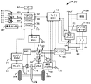
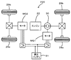
図1は、本発明の一実施例であるハイブリッド自動車20の構成の概略を示す構成図である。実施例のハイブリッド自動車20は、図示するように、エンジン22と、エンジン22の出力軸としてのクランクシャフト26にダンパを介してキャリアが接続されたプラネタリギヤ30と、プラネタリギヤ30のサンギヤに接続された発電可能なモータMG1と、プラネタリギヤ30に接続された駆動軸としてのリングギヤ軸に減速ギヤ35を介して接続されたモータMG2と、モータMG1及びモータMG2と電気エネルギのやりとりが可能な高圧バッテリ51と、高圧バッテリ51から電気エネルギの受け取りが可能な低圧バッテリ53と、ハイブリッド自動車20全体をコントロールするハイブリッド用電子制御ユニット70とを備える。
FIG. 1 is a configuration diagram showing an outline of the configuration of a
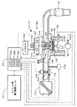
エンジン22は、例えばガソリン又は軽油などの炭化水素系の燃料により動力を出力可能な内燃機関として構成されており、図2に示すように、エアクリーナ122により清浄された空気をスロットルバルブ124を介して吸入すると共に燃料噴射弁126から燃料を噴射して吸入された空気と燃料とを混合し、この混合気を吸気バルブ128を介して燃焼室134に吸入し、点火プラグ130による電気火花によって爆発燃焼させて、そのエネルギにより押し下げられるピストン132の往復運動をクランクシャフト26の回転運動に変換する。また、吸気バルブ128には、吸気バルブ128の開閉タイミングを変更可能な可変バルブタイミング機構150が設けられている。なお、エンジン22からの排気は、排気バルブ129を開くことにより一酸化炭素(CO)や炭化水素(HC),窒素酸化物(NOx)の有害成分を浄化する浄化装置(三元触媒)137を介して外気へ排出される。
The
クランクシャフト26の一端には、図示しないクランクプーリが取り付けられており、クランクシャフト26とクランクプーリとが一体になって回転するようになっている。このクランクプーリは、図3に示すように、タイミングチェーン162を介して吸気カムシャフト127の一端に取り付けられた吸気カムシャフトプーリ164及び排気カムシャフト125の一端に取り付けられた排気カムシャフトプーリ123と連結している。なお、タイミングチェーン162はクランクプーリに設けられた図示しないスプロケットに掛け渡されている。したがって、クランクシャフト26の回転に伴いクランクプーリが回転すると、その回転に伴って吸気カムシャフトプーリ164及び排気カムシャフトプーリ123が回転し、これにより吸気カムシャフト127と排気カムシャフト125とにそれぞれ配列された吸気カム131と排気カム135とによって吸気バルブ128と排気バルブ129とがそれぞれ開閉する。
A crank pulley (not shown) is attached to one end of the
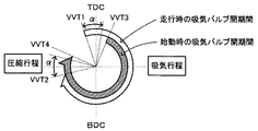
可変バルブタイミング機構150は、図2及び図3に示すように、吸気カムシャフト127の一端に取り付けられ吸気カムシャフト127を進角側又は遅角側にシフトさせる直流による電動式のVVT用モータ133を備えている。このVVT用モータ133を動作させることにより吸気カムシャフトプーリ164に対する吸気カムシャフト127の位相を連続的に変化させる。これにより、吸気バルブ128の開閉タイミングが変化する。なお、この種の可変バルブタイミング機構150の詳細は、例えば特開2004−3419号公報に開示されている。図4は、可変バルブタイミング機構150によって行なわれる吸気バルブ128の開閉タイミングを示すバルブタイミングダイアグラムである。図示するように、走行時は吸気行程の上死点(TDC)より少し手前の走行時進角開弁位置VVT1からα°の範囲内で走行状態に応じて吸気バルブ128を開弁し、吸気行程の下死点(BDC)を少し超えた走行時進角閉弁位置VVT2からα°の範囲内で走行状態に応じて吸気バルブ128を閉弁する。一方、エンジン始動時は、可変バルブタイミング機構150によって最大限遅角可能な最大遅角位置である始動時開弁位置VVT3で吸気バルブ128を開弁し、始動時閉弁位置VVT4で吸気バルブ128を閉弁する。また、本実施形態では、エンジン始動時のエンジン22が後述する低温基準値Trefを超えているときには、このように吸気バルブ128の開閉位置を最大遅角位置に設定するが、エンジン始動時のエンジン22が低温基準値Tref以下のときには、吸気バルブ128の開閉タイミングを最大遅角位置(図4の始動時開弁位置VVT3及び始動時閉弁位置VVT4)からの進角量ΔVVTでもって変更する。また、VVT用モータ133は、図1に示すように、低圧バッテリ53から電力が供給される第1経路R1と、低圧バッテリ53を介さずにDC/DCコンバータ55から電力が供給される第2経路R2とがあり、第2経路に設けられた2つのスイッチSR2のオンオフによりいずれの経路からVVT用モータ133に電力を供給するかが制御される。
As shown in FIGS. 2 and 3, the variable
エンジン22は、エンジン用電子制御ユニット(以下、エンジンECUという)24により制御されている。エンジンECU24は、CPU24aを中心とするマイクロプロセッサとして構成されており、CPU24aの他に処理プログラムを記憶するROM24bと、データを一時的に記憶するRAM24cと、図示しない入出力ポート及び通信ポートとを備える。エンジンECU24には、エンジン22の状態を検出する種々のセンサからの信号、例えば、クランクシャフト26の回転位置を検出するクランクポジションセンサ140からのクランクポジションやエンジン22の冷却水の温度を検出する水温センサ142からのエンジン水温Tw,燃焼室134へ吸排気を行なう吸気バルブ128や排気バルブ129を開閉するカムシャフトの回転位置を検出するカムポジションセンサ144からのカムポジション,スロットルバルブ124のポジションを検出するスロットルバルブポジションセンサ146からのスロットルポジション,エンジン22の吸入空気量を検出するバキュームセンサ148からの吸入空気量などが入力ポートを介して入力されている。また、エンジンECU24からは、エンジン22を駆動するための種々の制御信号、例えば、燃料噴射弁126への駆動信号や、スロットルバルブ124のポジションを調節するスロットルモータ136への駆動信号、イグナイタと一体化されたイグニッションコイル138への制御信号、VVT用モータ133への制御信号などが出力ポートを介して出力されている。なお、エンジンECU24は、ハイブリッド用電子制御ユニット70と通信しており、ハイブリッド用電子制御ユニット70からの制御信号によりエンジン22を運転制御すると共に必要に応じてエンジン22の運転状態に関するデータを出力する。
The
モータMG1及びモータMG2は、いずれも発電機として駆動することができると共に電動機として駆動できる周知の同期発電電動機として構成されており、インバータ41,42を介して高圧バッテリ51と電力のやりとりを行なう。モータMG1,MG2は、いずれもモータ用電子制御ユニット(以下、モータECUという)40により駆動制御されている。モータECU40には、モータMG1,MG2を駆動制御するために必要な信号、例えばモータMG1,MG2の回転子の回転位置を検出する図示しない回転位置検出センサからの信号や図示しない電流センサにより検出されるモータMG1,MG2に印加される相電流などが入力されており、モータECU40からは、インバータ41,42へのスイッチング制御信号が出力されている。モータECU40は、ハイブリッド用電子制御ユニット70と通信しており、ハイブリッド用電子制御ユニット70からの制御信号によってモータMG1,MG2を駆動制御すると共に必要に応じてモータMG1,MG2の運転状態に関するデータをハイブリッド用電子制御ユニット70に出力する。
Both the motor MG1 and the motor MG2 are configured as well-known synchronous generator motors that can be driven as generators and can be driven as motors, and exchange power with the high-
高圧バッテリ51は、本実施形態ではニッケル水素電池であり、インバータ41,42を介してモータMG1及びモータMG2と電気エネルギのやり取りを行う。また、高圧バッテリ51には、高圧系の電圧を低圧系の電圧に変換するDC/DCコンバータ55が接続されており、必要に応じて高圧バッテリ51からDC/DCコンバータ55を介して低圧バッテリ53に電気エネルギを供給する。すなわち、DC/DCコンバータ55を駆動制御することにより、高圧バッテリ51から供給された直流電圧をDC/DCコンバータ55で降圧し、この降圧した直流電圧を低圧バッテリ53に蓄積させる。これにより、高圧バッテリ51から低圧バッテリ53への充電を行うことができる。
The
低圧バッテリ53は、本実施形態では鉛蓄電池である。この低圧バッテリ53は、VVT用モータ133に電力を供給してVVT用モータ133を作動させる。また、車両に搭載された補機58に電気エネルギを供給して補機58を作動させたり、イグニッションスイッチ80からのオン信号に基づいてハイブリッドECU70に電力を供給してハイブリッドECU70を起動させたりする。
The
高圧バッテリ51及び低圧バッテリ53は、バッテリ用電子制御ユニット(以下、バッテリECUという)50によって管理されている。バッテリECU50には、高圧バッテリ51を管理するのに必要な信号、例えば、高圧バッテリ51の端子間に設置された電圧センサ52からの端子間電圧,高圧バッテリ51の出力端子に接続された電力ライン57に取り付けられた図示しない電流センサからの充放電電流,高圧バッテリ51に取り付けられた温度センサ56からの電池温度Tbなどが入力されており、高圧バッテリ51を管理するための残容量(SOC)を計算すると共に計算した残容量(SOC)と電池温度Tbやその入出力制限Win,Wout,高圧バッテリ51を充放電するための要求値である充放電要求パワーPb*などを計算し、必要に応じてデータを通信によりハイブリッド用電子制御ユニット70に出力する。また、バッテリECU50は、低圧バッテリ53を管理するのに必要な信号、例えば、低圧バッテリ53の端子間に設置された電圧センサ54からの端子間電圧Vb,低圧バッテリ53の出力端子に接続された電力ラインに取り付けられた図示しない電流センサからの充放電電流などを入力したり、スイッチSR2への制御信号を出力したりする。
The
ハイブリッド用電子制御ユニット70は、CPU72を中心とするマイクロプロセッサとして構成されており、CPU72の他に処理プログラムを記憶するROM74と、データを一時的に記憶するRAM76と、図示しない入出力ポート及び通信ポートとを備える。ハイブリッド用電子制御ユニット70には、イグニッションスイッチ80からのイグニッション信号,シフトレバー81の操作位置を検出するシフトポジションセンサ82からのシフトポジションSP,アクセルペダル83の踏み込み量を検出するアクセルペダルポジションセンサ84からのアクセル開度Acc,ブレーキペダル85の踏み込み量を検出するブレーキペダルポジションセンサ86からのブレーキペダルポジションBP,車速センサ87からの車速Vなどが入力ポートを介して入力されている。ハイブリッド用電子制御ユニット70は、前述したように、エンジンECU24やモータECU40,バッテリECU50と通信ポートを介して接続されており、エンジンECU24やモータECU40,バッテリECU50と各種制御信号やデータのやりとりを行なっている。
The hybrid
こうして構成された実施例のハイブリッド自動車20は、運転者によるアクセルペダル83の踏み込み量に対応するアクセル開度Accと車速Vとに基づいて駆動軸としてのリングギヤ軸に出力すべき要求トルクを計算し、この要求トルクに対応する要求動力がリングギヤ軸に出力されるように、エンジン22とモータMG1とモータMG2とが運転制御される。エンジン22とモータMG1とモータMG2の運転制御としては、要求動力に見合う動力がエンジン22から出力されるようにエンジン22を運転制御すると共にエンジン22から出力される動力のすべてがプラネタリギヤ30とモータMG1とモータMG2とによってトルク変換されてリングギヤ軸に出力されるようモータMG1及びモータMG2を駆動制御するトルク変換運転モードや要求動力と高圧バッテリ51の充放電に必要な電力との和に見合う動力がエンジン22から出力されるようにエンジン22を運転制御すると共に高圧バッテリ51の充放電を伴ってエンジン22から出力される動力の全部又はその一部がプラネタリギヤ30とモータMG1とモータMG2とによるトルク変換を伴って要求動力がリングギヤ軸に出力されるようモータMG1及びモータMG2を駆動制御する充放電運転モード、エンジン22の運転を停止してモータMG2からの要求動力に見合う動力をリングギヤ軸に出力するよう運転制御するモータ運転モードがある。
The
次に、実施例のハイブリッド自動車20の動作、特にモータ運転モードからトルク変換運転モードや充放電運転モードに移行するときのようにエンジン22を運転停止状態から始動する際の動作について説明する。図5は、ハイブリッド用電子制御ユニット70により実行される始動制御ルーチンの一例を示すフローチャートである。このルーチンは、エンジン22を始動する際に実行される。ここで、吸気バルブ128の開弁位置VVTo及び閉弁位置VVTcは、本実施形態では、吸気バルブ128が始動時開弁位置VVT3で開弁するとともに始動時閉弁位置VVT4で閉弁する、つまり開閉タイミングが最遅角位置になるよう(図4参照)、エンジン22の運転が停止した直後にVVT用モータ133によって設定するものとした。
Next, the operation of the
始動制御ルーチンが実行されると、ハイブリッド用電子制御ユニット70のCPU72は、まず、アクセルペダルポジションセンサ84からのアクセル開度Accや車速センサ87からの車速V,エンジン22の回転数NeやモータMG1,MG2の回転数Nm1,Nm2,エンジンのモータリングが開始されてからの時間t,高圧バッテリ51の出力制限Woutなど制御に必要なデータを入力する(ステップS100)。ここで、エンジン22の回転数Neは、クランクシャフト26に取り付けられたクランクポジションセンサ140からの信号に基づいて計算されたものをエンジンECU24から通信により入力するものとした。また、モータMG1,MG2の回転数Nm1,Nm2は、回転位置検出センサ43,44により検出されるモータMG1,MG2の回転子の回転位置に基づいて計算されたものをモータECU40から通信により入力するものとした。モータリングが開始されてからの時間tは、エンジン22の始動要求がなされたときに計時が開始されるタイマの計時時間を入力するものとした。高圧バッテリ51の出力制限Woutは、温度センサ56により検出された高圧バッテリ51の電池温度Tbと高圧バッテリ51の残容量(SOC)とに基づいて設定されたものをバッテリECU50から通信により入力するものとした。
When the start control routine is executed, the
こうしてデータを入力すると、入力したアクセル開度Accと車速Vとに基づいて車両に要求される要求トルクTr*を設定する(ステップS102)。要求トルクTr*は、本実施形態では、アクセル開度Accと車速Vと要求トルクTr*との関係を予め定めて要求トルク設定用マップとしてROM74に記憶しておき、アクセル開度Accと車速Vとが与えられると記憶したマップから対応する要求トルクTr*を導出して設定するものとした。図6に要求トルク設定用マップの一例を示す。
When the data is input in this way, the required torque Tr * required for the vehicle is set based on the input accelerator opening Acc and the vehicle speed V (step S102). In the present embodiment, the required torque Tr * is stored in the
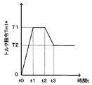
続いて、モータリングが開始されてからの時間tに基づいてモータMG1のトルク指令Tm1*を設定する(ステップS104)。ここで、モータMG1のトルク指令Tm1*は、本実施形態では、モータリングが開始されてからの時間tとトルク指令Tm1*との関係を予め定めてトルク指令設定用マップとしてROM74に記憶しておき、時間tが与えられると記憶したマップから対応するトルク指令Tm1*を導出して設定するものとした。トルク指令設定用マップの一例を図7に示す。モータMG1のトルク指令Tm1*は、図示するように、エンジン22の始動要求がなされた時点(t=0)から徐々に大きくなって時間t1以降に比較的大きな所定トルクT1となるよう設定されると共にその後に所定時間が経過した時間t2から徐々に小さくなって時間t3以降に所定トルクT2となるよう設定される。ここで、所定トルクT1および所定時間(時間t1〜t2)は、エンジン22の回転数Neを迅速に上昇させることができるトルクおよび時間として設定され、エンジン22や高圧バッテリ51の性能などにより定められる。また、所定トルクT2は、モータリング消費電力を抑制しながらエンジン22の回転数Neをさらに上昇させることができるトルクとして設定され、エンジン22や高圧バッテリ51の性能などにより定められる。また、モータMG1のトルク指令Tm1*は、エンジン22の回転数が所定の始動回転数Nstartに達したあとはエンジン22が始動回転数Nstartで回転し続けるようなトルクに設定される。
Subsequently, a torque command Tm1 * for the motor MG1 is set based on the time t after the start of motoring (step S104). In this embodiment, the torque command Tm1 * of the motor MG1 is stored in the
こうしてモータMG1のトルク指令Tm1*を設定すると、続いて、エンジン水温Twが低温基準値Tref以下であるか否かを判定する(ステップS106)。ここで、エンジン水温Twは、エンジン22の冷却水の温度を検出する水温センサ142からの冷却水温をエンジンECU24から通信により入力するものとした。また、低温基準値Trefは、エンジン温度が低いためにエンジン22に使用するオイルの粘性が高くなることでエンジン回転数Neの上昇が極めて小さくなる極低温状態の上限値であり、実験を繰り返すことにより定めた値とした。この極低温状態の上限値としては、例えば、極低温状態を−30℃以下とすると、その上限値は−30℃となる。いま、エンジン22の温度が低温基準値Trefよりも高い場合を考えると、ステップS106で否定的な判定がなされてステップS122に進み、エンジン22の回転数Neが予め定めた所定の始動回転数Nstart以上か否かを判定する(ステップS122)。このとき、エンジン22を始動しようとした直後を考えれば、エンジン22の回転数Neは始動回転数Nstart未満であるから、ステップS122で否定的な判定がなされ、モータMG2のトルク指令Tm2*を設定した後、設定したトルク指令Tm1*,Tm2*をモータECU40に送信する(ステップS128)。トルク指令Tm1*,Tm2*を受信したモータECU40は、トルク指令Tm1*でモータMG1が駆動されると共にトルク指令Tm2*でモータMG2が駆動されるようインバータ41,42のスイッチング素子のスイッチング制御を行う。
When the torque command Tm1 * of the motor MG1 is thus set, it is subsequently determined whether or not the engine water temperature Tw is equal to or lower than the low temperature reference value Tref (step S106). Here, as the engine water temperature Tw, the cooling water temperature from the
ここで、モータMG2の要求トルクTm2*は、高圧バッテリ51の出力制限WoutとモータMG1の消費電力(つまりトルク指令Tm1*にモータ回転数Nm1を乗じた値)との偏差をモータMG2の回転数Nm2で除することによりモータMG2から出力可能なトルクの上限としてのトルク制限Tmaxを次式(1)により計算すると共に、要求トルクTr*とモータMG1のトルク指令Tm1*とプラネタリギヤ30のギヤ比ρと減速ギヤ35のギヤ比Grとを用いてモータMG2から出力すべきトルクとしての仮モータトルクTm2tmpを式(2)により計算する。そして、各々計算したトルク制限Tmaxと仮モータトルクTm2tmpとを比較して小さい方をモータMG2のトルク指令Tm2*として設定する。このようにモータMG2のトルク指令Tm2*を設定することにより、モータMG1でエンジン22をモータリングすることによって駆動軸としてのリングギヤ軸32aに作用する反力トルクをモータMG2から出力されるトルクでキャンセルすると共に、リングギヤ軸32aに出力すべき要求トルクTr*を高圧バッテリ51の出力制限Woutの範囲内で制限したトルクとして出力することができる。
Here, the required torque Tm2 * of the motor MG2 is calculated by taking the deviation between the output limit Wout of the
Tmax=(Wout-Tm1*・Nm1)/Nm2 …(1)
Tm2tmp=(Tr*+Tm1*/ρ)/Gr …(2)
Tmax = (Wout-Tm1 * ・ Nm1) / Nm2 (1)
Tm2tmp = (Tr * + Tm1 * / ρ) / Gr (2)
なお、式(2)は、図8の共線図を用いれば容易に導くことができる。図中、左のS軸はモータMG1の回転数Nm1でもあるサンギヤの回転数を示し、C軸はエンジン22の回転数Neでもあるキャリアの回転数を示し、R軸はモータMG2の回転数Nm2を減速ギヤ35のギヤ比Grで除した値でもあるリングギヤの回転数Nrを示す。また、S軸,C軸およびR軸上の矢印は各軸に負荷されるトルクを示す。ここでは、エンジン22はクランキング状態にあるからキャリアにはエンジン22のトルクが作用せず、サンギヤに作用するモータMG1のトルク(トルク指令Tm1*)でもってエンジン22のクランクシャフト26が下支えされる。このときリングギヤ軸には反力トルクが作用するためこれをキャンセルするためにモータMG2からキャンセルトルク(=−Tm1*/ρ)が出力される。
Equation (2) can be easily derived by using the alignment chart of FIG. In the figure, the left S-axis indicates the rotation speed of the sun gear which is also the rotation speed Nm1 of the motor MG1, the C-axis indicates the rotation speed of the carrier which is also the rotation speed Ne of the
続いて、エンジン22が完爆したか否かを判定する(ステップS130)。ここで、エンジン22が完爆したか否かの判定は、本実施形態では、エンジン22の回転数が所定の始動回転数Nstartよりも所定回転数だけ高い判定基準値Nrefを上回ったか否かで行うものとした。いま、エンジン22の回転数Neが所定の始動回転数Nstartに達していないときを考えているから、エンジン22の燃料噴射制御や点火制御等といった燃焼制御は未だ開始されていないため、エンジン22は完爆しておらず、ステップS130では否定的な判定がなされ、ステップS100に戻る。
Subsequently, it is determined whether or not the
ステップS100〜S106及びS122の処理が繰り返し実行されているうちにエンジン22の回転数Neが所定の始動回転数Nstart以上になると、ステップS122で肯定的な判定がなされ、エンジン22の燃料噴射制御や点火制御等といった燃焼制御が実行されているか否かを判定する(ステップS124)。いま、初めてエンジン22の回転数Neが所定の始動回転数Nstart以上になったときを考えると、まだエンジン22の燃焼制御は実行されていないため、この燃焼制御の開始をエンジンECU24に指示し(ステップS126)、ステップS128及びS130の処理を実行する。これにより、エンジンECU24は、エンジン22の燃焼制御を開始する。このとき、吸気バルブ128の開閉タイミングは最遅角位置に設定されているから、圧縮行程における筒内の圧力(筒内圧縮圧力)が小さくなる。したがって、エンジン22のモータリング時には筒内圧縮圧力の上昇を小さくしてエンジン回転数Neを上昇しやすくすると共に燃焼制御の際に発生する燃焼エネルギを小さくして始動時のショックを低減することができる。そして、次回の始動制御ルーチンでは、既にエンジン22の燃焼制御を開始しているため、ステップS100〜S106及びS122のあとのステップS124で肯定的な判定がなされ、ステップS128及びS130の処理を実行する。
If the rotational speed Ne of the
こうして、モータMG1のトルク指令Tm1*のトルクでエンジン22をモータリングしている最中にエンジン22の燃焼制御が行われた結果エンジン22が完爆すると、ステップS130で肯定的な判定がなされ、本始動制御ルーチンを終了する。
Thus, when the
次に、エンジン水温Twが低温基準値Tref以下である場合を考える。この場合、ステップS106で肯定的な判定がなされ、続いて低圧バッテリ53の端子間電圧Vbが低レベル基準値Vref以下であるか否かを判定する(ステップS108)。ここで、低レベル基準値Vrefは、VVT用モータ133を駆動させるのに十分な電力を低圧バッテリ53からVVT用モータ133に供給することができない電圧範囲の上限値であり、実験を繰り返すことにより定めた値とした。低圧バッテリ53の端子間電圧Vbが低レベル基準値Vrefよりも大きいときには、VVT用モータ133を駆動させるのに十分な電力を低圧バッテリ53から供給することができると判断し、スイッチSR2をオンにせず、吸気バルブ128の開閉タイミングを進角量ΔVVTだけ進角させる動作が完了しているか否かを判定する(ステップS114)。いま、吸気バルブ128の開閉タイミングを進角量ΔVVTだけ進角させる動作を未だ開始していないときを考えると、ステップS114で否定的な判定がなされ、吸気バルブ128の開閉タイミングの進角が実行中であるか否かを判定する(ステップS116)。ここでは、吸気バルブ128の開閉タイミングの進角を開始していないときを考えているから、ステップS116では否定的な判定がなされ、吸気バルブ128の開閉タイミングの進角を開始するようエンジンECU24に指示し(ステップS118)、ステップS128及びS130の処理を実行する。これにより、吸気バルブ128の開閉タイミングの進角動作が開始される。このとき、スイッチSR2はオフのままであることから、VVT用モータ133には低圧バッテリ53から電力を供給する第1経路R1により電力が供給されることになる。なお、ここでは、エンジン22の燃焼制御は未だ開始されていないため、エンジン22は完爆しておらず、ステップS130では否定的な判定がなされ、ステップS100に戻る。そして、次回の始動制御ルーチンでは、既に吸気バルブ128の開閉タイミングの進角を開始していることから、ステップS100〜S108,S114のあとのステップS116で肯定的な判定がなされ、ステップS128以降の処理を実行する。
Next, consider a case where the engine water temperature Tw is equal to or lower than the low temperature reference value Tref. In this case, an affirmative determination is made in step S106, and then it is determined whether or not the voltage Vb between the terminals of the
こうしてステップS100〜S108,S114〜S118,S128〜S130の処理が繰り返し実行されているうちに開閉タイミングが最遅角位置から進角量ΔVVTだけ進角すると、ステップS114で肯定的な判定がなされ、VVT用モータ133による吸気バルブ128の進角を停止させ(ステップS120)、ステップS122以降の処理を実行する。これにより、エンジン水温Twが低温基準値Tref以下のときには、吸気バルブ128の開閉タイミングを最遅角位置から進角量ΔVVTだけ進角させることができる。このように、エンジン22の冷却水温Tが低くエンジン22のオイルの粘性が高いなどに理由によりエンジン22を始動する際に発生する摩擦が大きいときには、温度が高いときに比べて吸気バルブ128の開閉タイミングを進角側にさせてから燃焼制御を行なうため、エンジン22の気筒内への吸入空気量を多くすることができ、この結果、燃焼制御による燃焼エネルギを増大させることができる。なお、進角量ΔVVTは、燃焼エネルギに見合った吸入空気量がエンジン22の気筒内に吸入されるように予め定められている。
Thus, if the opening / closing timing is advanced by the advance amount ΔVVT from the most retarded position while the processes of steps S100 to S108, S114 to S118, and S128 to S130 are repeatedly executed, a positive determination is made in step S114. The advance angle of the
一方、ステップS108で低圧バッテリ53の端子間電圧Vbが低レベル基準値Vref以下のときには、スイッチSR2がオンか否かを判定する(ステップS110)。そして、スイッチSR2がオフのときにはスイッチSR2をオンにするようバッテリECU50に指示し(ステップS112)、スイッチSR2がオンのときにはそのままステップS114以降の処理を実行する。このように、低圧バッテリ53の端子間電圧Vbが低レベル基準値Vref以下のときには、VVT用モータ133を駆動させるのに十分な電力を低圧バッテリ53から供給することができないため、スイッチSR2をオンにすることにより、低圧バッテリ53を介さずにDC/DCコンバータ55から電力を供給する第2経路R2によりVVT用モータ133に電力を供給することができる。これにより、低圧バッテリ53の充電状態が低レベル状態にあり低圧バッテリ53からの電力のみではVVT用モータ133を駆動させることができない場合であっても、DC/DCコンバータ55からの電力により進角動作が確実に行われるため、エンジン水温Twが低温基準値Tref以下である場合にも十分な燃焼エネルギを得ることができる。その結果、エンジン22の良好な始動性を確保することができる。
On the other hand, when the inter-terminal voltage Vb of the
以上説明した実施例のハイブリッド自動車20によれば、エンジン22を始動する際、エンジン水温Twが低温基準値Tref以下にあるために吸気バルブ128の開閉タイミングを最遅角位置から進角させる必要があるときには、第1経路R1又は第2経路R2からVVT用モータ133に電力を供給する。したがって、低圧バッテリ53の充電状態が低レベル状態にあるときであっても、低圧バッテリ53を介さずにDC/DCコンバータ55からVVT用モータ133に電力が供給されるため、エンジン22を始動する際、エンジン22の停止時に設定されていた開閉タイミングを変更する必要があるときであっても確実に変更することができる。
According to the
なお、本発明は上述した実施例に何ら限定されることはなく、本発明の技術的範囲に属する限り種々の態様で実施し得ることはいうまでもない。 In addition, this invention is not limited to the Example mentioned above at all, and as long as it belongs to the technical scope of this invention, it cannot be overemphasized that it can implement with a various aspect.
例えば、上述した実施例のハイブリッド自動車20では、VVT用モータ133に電力を供給する経路として第2経路R2を設けたが、図9の変形例のハイブリッド自動車120に示すように、第2経路R2の代わりに家庭用電源からAC/DCコンバータ152を介してVVT用モータ133に電力を供給する第3経路R3を設けるとしてもよい。このとき、図5の始動制御ルーチンにおいて、ステップS108で低圧バッテリ53の端子間電圧Vbが低レベル基準値Vref以下のときには、スイッチS110及びステップS112では、スイッチSR2をオンする代わりに第3経路R3に設けられたスイッチSR3をオンにする。あるいは、第2経路R2と共に第3経路R3を設けるとしてもよい。
For example, in the
上述した実施例のハイブリッド自動車20では、ステップS108で低圧バッテリ53の充電状態が低レベル状態にあるときにスイッチSR2をオンにしたが、低圧バッテリ53の放電状態が低レベル状態にあるときにスイッチSR2をオンにするとしてもよい。
In the
上述した実施例のハイブリッド自動車20では、ステップS106でエンジン22の温度が低温基準値Tref以下であり且つステップS108で低圧バッテリ53の充電状態が低レベル状態にあるときにスイッチSR2をオンにしたが、ステップS106でエンジン22の温度が低温基準値Tref以下にあると判定されたときには、ステップS108の処理を行なうことなくスイッチSR2をオンにするとしてもよい。エンジン22の温度が低いときには低圧バッテリ53の性能が低下しやすいため、こうすればエンジン22の温度が低いときには常に第2経路R2からVVT用モータ133に電力を供給することができる。
In the
上述した実施例のハイブリッド自動車20では、第2経路R2のみにスイッチSR2を設けたが、第1経路R1にもスイッチSR1を設けるとしてもよい。この場合、低圧バッテリ53からVVT用モータ133に電力を供給するときはスイッチSR1をオンにしてスイッチSR2をオフにし、低圧バッテリ53を介さずにDC/DCコンバータ55からVVT用モータ133に電力を供給するときはスイッチSR2をオンにしてスイッチSR1をオフにする。
In the
実施例のハイブリッド自動車20では、モータMG2の動力を減速ギヤ35により変速してリングギヤ軸32aに出力するものとしたが、図10の変形例のハイブリッド自動車220に例示するように、モータMG2の動力をリングギヤ軸が接続された車軸(駆動輪28a,28bが接続された車軸)とは異なる車軸(図10における車輪29a,29bに接続された車軸)に接続するものとしてもよい。
In the
実施例のハイブリッド自動車20では、エンジン22の動力をプラネタリギヤ30を介して駆動輪28a,28bに接続された駆動軸としてのリングギヤ軸に出力するものとしたが、図11の変形例のハイブリッド自動車320に例示するように、エンジン22のクランクシャフト26に接続されたインナーロータ232と駆動輪28a,28bに動力を出力する駆動軸に接続されたアウターロータ234とを有し、エンジン22の動力の一部を駆動軸に伝達すると共に残余の動力を電力に変換する対ロータ電動機230を備えるものとしてもよい。
In the
実施例では、ハイブリッド自動車20として説明したが、こうしたハイブリッド自動車20に限定されるものではなく、エンジン22によって駆動されるエンジン自動車に適用することもできる。また、自動車以外の車両、例えば列車や船舶などに適用することもできる。
In the embodiment, the
20,120,220,320 ハイブリッド自動車、22 エンジン、24 エンジン用電子制御ユニット(エンジンECU)、24a CPU、24b ROM、24c RAM、26 クランクシャフト、28a,28b 駆動輪、29a,29b 車輪、30 プラネタリギヤ、35 減速ギヤ、40 モータ用電子制御ユニット(モータECU)、41,42 インバータ、50 バッテリ用電子制御ユニット(バッテリECU)、51 高圧バッテリ、52 電圧センサ、53低圧バッテリ、54 電圧センサ、57 電力ライン、55 DC/DCコンバータ、56 温度センサ、58 補機、70 ハイブリッド用電子制御ユニット、72 CPU、74 ROM、76 RAM、80 イグニッションスイッチ、81 シフトレバー、82 シフトポジションセンサ、83 アクセルペダル、84 アクセルペダルポジションセンサ、85 ブレーキペダル、86 ブレーキペダルポジションセンサ、87 車速センサ、122 エアクリーナ、123 排気カムシャフトプーリ、124 スロットルバルブ、125 排気カムシャフト、126 燃料噴射弁、127 吸気カムシャフト、128 吸気バルブ、129 排気バルブ、130 点火プラグ、131 吸気カム、132 ピストン、133 VVT用モータ、134 燃焼室、135 排気カム、136 スロットルモータ、137 浄化装置、138 イグニッションコイル、140 クランクポジションセンサ、142 水温センサ、144 カムポジションセンサ、146 スロットルバルブポジションセンサ、148 バキュームセンサ、150 可変バルブタイミング機構、152 AC/DCコンバータ、162 タイミングチェーン、164 吸気カムシャフトプーリ、230 対ロータ電動機、232 インナーロータ、234 アウターロータ、MG1,MG2 モータ、SR2,SR3 スイッチ。 20, 120, 220, 320 Hybrid vehicle, 22 engine, 24 engine electronic control unit (engine ECU), 24a CPU, 24b ROM, 24c RAM, 26 crankshaft, 28a, 28b drive wheel, 29a, 29b wheel, 30 planetary gear , 35 reduction gear, 40 motor electronic control unit (motor ECU), 41, 42 inverter, 50 battery electronic control unit (battery ECU), 51 high voltage battery, 52 voltage sensor, 53 low voltage battery, 54 voltage sensor, 57 power Line, 55 DC / DC converter, 56 Temperature sensor, 58 Auxiliary machine, 70 Hybrid electronic control unit, 72 CPU, 74 ROM, 76 RAM, 80 Ignition switch, 81 Shift lever, 82 Ft position sensor, 83 accelerator pedal, 84 accelerator pedal position sensor, 85 brake pedal, 86 brake pedal position sensor, 87 vehicle speed sensor, 122 air cleaner, 123 exhaust camshaft pulley, 124 throttle valve, 125 exhaust camshaft, 126 fuel injection valve 127 intake camshaft, 128 intake valve, 129 exhaust valve, 130 spark plug, 131 intake cam, 132 piston, 133 VVT motor, 134 combustion chamber, 135 exhaust cam, 136 throttle motor, 137 purification device, 138 ignition coil, 140 Crank position sensor, 142 Water temperature sensor, 144 Cam position sensor, 146 Throttle valve position sensor, 148 Vacuum Sensor, 150 variable valve timing mechanism, 152 AC / DC converter, 162 timing chain, 164 intake camshaft pulley, 230 rotor motor, 232 inner rotor, 234 outer rotor, MG1, MG2 motor, SR2, SR3 switch.
Claims (4)
高圧電源からの高電圧を電力変換回路により降圧することによって得られる低電圧を蓄電可能な低圧蓄電装置から前記動弁用電動機に電力を供給する第1の経路と、
前記電力変換回路により降圧することによって得られる低電圧を前記低圧蓄電装置を介さずに前記動弁用電動機に供給する第2の経路と、
前記内燃機関の温度を検出する温度検出手段と、
前記第2の経路から前記動弁用電動機に電力を供給するか否かを切り替える経路切り替え手段と、
前記内燃機関を始動する際、該内燃機関の停止時に設定されていた開閉タイミングを変更する必要があるときには、前記第1の経路又は前記第2の経路から電力が供給される前記動弁用電動機を制御することにより前記開閉タイミングを変更する制御手段と、
を備え、
前記制御手段は、前記第1の経路又は前記第2の経路から電力が供給される前記動弁用電動機を制御することにより前記開閉タイミングを変更するにあたり、前記温度検出手段により前記内燃機関の温度が所定の低温範囲に入ることが検出されたときには、前記第2の経路から前記動弁用電動機に電力が供給されるよう前記経路切り替え手段を制御し、
前記経路切り替え手段は、前記第2の経路に設けられたスイッチのオンオフを切り替えることにより、前記第2の経路から前記動弁用電動機に電力を供給するか否かの切り替えを行う、
可変動弁装置。 A variable valve operating device capable of changing an opening / closing timing of at least one of an intake valve and an exhaust valve of an internal combustion engine by a valve operating motor,
A first path for supplying electric power to the valve operating motor from a low-voltage power storage device capable of storing a low voltage obtained by stepping down a high voltage from a high-voltage power supply by a power conversion circuit;
A second path for supplying a low voltage obtained by stepping down by the power conversion circuit to the valve operating motor without going through the low-voltage power storage device;
Temperature detecting means for detecting the temperature of the internal combustion engine;
Path switching means for switching whether to supply electric power to the valve operating motor from the second path;
When starting the internal combustion engine, when it is necessary to change the opening / closing timing set when the internal combustion engine is stopped, the valve motor is supplied with electric power from the first path or the second path Control means for changing the opening and closing timing by controlling
With
The control means controls the temperature of the internal combustion engine by the temperature detection means when changing the opening / closing timing by controlling the valve operating motor to which electric power is supplied from the first path or the second path. There when it is detected that falls within a predetermined low temperature range, it controls the path switching means so that power is supplied from the second path to the electric motor for the valve operating,
The path switching means switches whether to supply power to the valve operating motor from the second path by switching on and off a switch provided in the second path.
Variable valve gear.
前記バルブを開閉させるカムが設けられたカムシャフトと予め定められた位置関係を保った状態で該カムシャフトに固定され、前記内燃機関の回転に伴って回転する基準プーリ、
を備え、
前記動弁用電動機は、前記基準プーリと前記カムシャフトとの位置関係を変更可能である、
可変動弁装置。 The variable valve operating apparatus according to claim 1,
A reference pulley that is fixed to the camshaft in a state in which a predetermined positional relationship is maintained with a camshaft provided with a cam for opening and closing the valve, and that rotates with the rotation of the internal combustion engine;
With
The valve motor can change the positional relationship between the reference pulley and the camshaft.
Variable valve gear.
前記内燃機関を始動する際、該内燃機関の停止時に設定されていた開閉タイミングを変更する必要があるときには、高圧電源からの高電圧を電力変換回路により降圧することによって得られる低電圧を蓄電可能な低圧蓄電装置から前記動弁用電動機に電力を供給する第1の経路又は前記電力変換回路により降圧することによって得られる低電圧を前記低圧蓄電装置を介さずに前記動弁用電動機に供給する第2の経路から電力が供給される前記動弁用電動機を制御することにより前記開閉タイミングを変更するにあたり、前記内燃機関の温度が所定の低温範囲に入ることが検出されたときには、前記第2の経路に設けられたスイッチのオンオフを切り替えることにより、前記第2の経路から前記動弁用電動機に電力が供給されるようにする、
可変動弁装置の制御方法。
A control method for a variable valve operating apparatus capable of changing an opening / closing timing of at least one of an intake valve and an exhaust valve of an internal combustion engine by a valve operating motor,
When starting the internal combustion engine, when it is necessary to change the opening and closing timing set when the internal combustion engine is stopped, it is possible to store the low voltage obtained by stepping down the high voltage from the high-voltage power supply by the power conversion circuit A low voltage obtained by stepping down the electric power from a low-voltage power storage device to the valve-operated motor through a first path or the power conversion circuit is supplied to the valve-operated motor without going through the low-voltage power storage device. When it is detected that the temperature of the internal combustion engine falls within a predetermined low temperature range when changing the opening / closing timing by controlling the valve operating motor supplied with electric power from the second path, the second By switching on / off of a switch provided in the path, power is supplied from the second path to the valve motor.
Control method of variable valve operating apparatus.
Priority Applications (5)
| Application Number | Priority Date | Filing Date | Title |
|---|---|---|---|
| JP2006145786A JP4910482B2 (en) | 2006-05-25 | 2006-05-25 | Variable valve operating device, control method thereof, and vehicle equipped with the same |
| CN2007800127956A CN101421499B (en) | 2006-05-25 | 2007-04-19 | Variable valve-actuating device, control method for the device, and vehicle carrying the device |
| US12/084,825 US7765964B2 (en) | 2006-05-25 | 2007-04-19 | Variable valve operating device, control method of variable valve operating device, and vehicle equipped with variable valve operating device |
| PCT/JP2007/058543 WO2007138801A1 (en) | 2006-05-25 | 2007-04-19 | Variable valve-actuating device, control method for the device, and vehicle carrying the device |
| EP07741979.4A EP2020493B1 (en) | 2006-05-25 | 2007-04-19 | Variable valve-actuating device, control method for the device, and vehicle carrying the device |
Applications Claiming Priority (1)
| Application Number | Priority Date | Filing Date | Title |
|---|---|---|---|
| JP2006145786A JP4910482B2 (en) | 2006-05-25 | 2006-05-25 | Variable valve operating device, control method thereof, and vehicle equipped with the same |
Publications (2)
| Publication Number | Publication Date |
|---|---|
| JP2007315290A JP2007315290A (en) | 2007-12-06 |
| JP4910482B2 true JP4910482B2 (en) | 2012-04-04 |
Family
ID=38778323
Family Applications (1)
| Application Number | Title | Priority Date | Filing Date |
|---|---|---|---|
| JP2006145786A Active JP4910482B2 (en) | 2006-05-25 | 2006-05-25 | Variable valve operating device, control method thereof, and vehicle equipped with the same |
Country Status (5)
| Country | Link |
|---|---|
| US (1) | US7765964B2 (en) |
| EP (1) | EP2020493B1 (en) |
| JP (1) | JP4910482B2 (en) |
| CN (1) | CN101421499B (en) |
| WO (1) | WO2007138801A1 (en) |
Families Citing this family (23)
| Publication number | Priority date | Publication date | Assignee | Title |
|---|---|---|---|---|
| JP4222414B2 (en) * | 2006-12-04 | 2009-02-12 | トヨタ自動車株式会社 | POWER OUTPUT DEVICE, HYBRID VEHICLE HAVING THE SAME, AND METHOD FOR CONTROLLING POWER OUTPUT DEVICE |
| JP4169081B1 (en) * | 2007-05-25 | 2008-10-22 | トヨタ自動車株式会社 | POWER OUTPUT DEVICE, HYBRID VEHICLE HAVING THE SAME, AND METHOD FOR CONTROLLING POWER OUTPUT DEVICE |
| US8098041B2 (en) * | 2007-11-04 | 2012-01-17 | GM Global Technology Operations LLC | Method of charging a powertrain |
| CN101282087B (en) * | 2008-04-25 | 2011-06-08 | 奇瑞汽车股份有限公司 | Method for converting DC/DC of double-voltage for vehicle |
| US8197383B2 (en) * | 2008-06-25 | 2012-06-12 | Ford Global Technologies, Llc | Multi-stroke hybrid propulsion system |
| US8148949B2 (en) * | 2009-02-24 | 2012-04-03 | American Axle & Manufacturing, Inc. | Use of high frequency transformer to charge HEV batteries |
| JP5447015B2 (en) * | 2010-03-08 | 2014-03-19 | トヨタ自動車株式会社 | Spark ignition internal combustion engine |
| JP5454789B2 (en) * | 2010-04-27 | 2014-03-26 | 三菱自動車工業株式会社 | Control device for electric vehicle |
| WO2012056535A1 (en) * | 2010-10-27 | 2012-05-03 | トヨタ自動車株式会社 | Control device for internal combustion engine |
| WO2012056527A1 (en) * | 2010-10-27 | 2012-05-03 | トヨタ自動車 株式会社 | Control device for in-vehicle internal combustion engine |
| WO2012125158A1 (en) * | 2011-03-15 | 2012-09-20 | International Truck Intellectual Property Company, Llc | Hybrid electic vehicle power management system |
| DE112011105587B4 (en) * | 2011-09-02 | 2018-05-30 | Toyota Jidosha Kabushiki Kaisha | Vehicle engine control device |
| KR101305605B1 (en) * | 2011-11-25 | 2013-09-09 | 엘에스산전 주식회사 | Power supply system for electric vehicle |
| JP5699919B2 (en) * | 2011-12-01 | 2015-04-15 | 株式会社デンソー | Warm-up operation control device |
| KR101684500B1 (en) * | 2011-12-06 | 2016-12-09 | 현대자동차 주식회사 | Method for controlling enging of hybrid electric vehicle |
| CN104169149B (en) * | 2012-03-16 | 2016-12-21 | 日产自动车株式会社 | Hybrid power drives driving dynamic control device and driving control method of electric automobile |
| JP5772803B2 (en) * | 2012-11-29 | 2015-09-02 | トヨタ自動車株式会社 | Control device for internal combustion engine |
| JP5893586B2 (en) * | 2013-06-18 | 2016-03-23 | 本田技研工業株式会社 | Valve timing control device for internal combustion engine |
| JP2015110383A (en) * | 2013-12-06 | 2015-06-18 | トヨタ自動車株式会社 | Hybrid vehicle |
| JP5958457B2 (en) * | 2013-12-13 | 2016-08-02 | トヨタ自動車株式会社 | Hybrid vehicle |
| CN107244244A (en) * | 2017-06-01 | 2017-10-13 | 北京新能源汽车股份有限公司 | Charge control method and system |
| CN111149270B (en) * | 2017-09-22 | 2023-10-31 | 株式会社电装 | Vehicle power supply system and power supply control device |
| FR3136732A1 (en) * | 2022-06-20 | 2023-12-22 | Psa Automobiles Sa | MONITORING A COMPUTER ASSOCIATED WITH AN ELECTRIC DRIVE MACHINE OF A VEHICLE |
Family Cites Families (17)
| Publication number | Priority date | Publication date | Assignee | Title |
|---|---|---|---|---|
| JPS61169641A (en) * | 1985-01-23 | 1986-07-31 | Toyota Motor Corp | Valve timing control device for internal-combustion engine with knocking control device |
| JP3185439B2 (en) * | 1993-01-22 | 2001-07-09 | トヨタ自動車株式会社 | Valve timing control device for internal combustion engine |
| JP3711720B2 (en) * | 1997-11-28 | 2005-11-02 | 株式会社デンソー | Hybrid electric vehicle |
| DE69942448D1 (en) | 1998-03-19 | 2010-07-15 | Hitachi Ltd | HYBRID VEHICLE |
| JP2000034913A (en) | 1998-07-17 | 2000-02-02 | Toyota Motor Corp | Variable valve system for internal combustion engine |
| JP2000257453A (en) * | 1999-01-07 | 2000-09-19 | Nissan Motor Co Ltd | Valve controller for engine |
| JP3478193B2 (en) * | 1999-05-24 | 2003-12-15 | トヨタ自動車株式会社 | Power monitoring device |
| JP2003184585A (en) * | 2001-12-14 | 2003-07-03 | Denso Corp | Control device for internal combustion engine |
| JP3857146B2 (en) | 2002-01-16 | 2006-12-13 | 本田技研工業株式会社 | Control device for hybrid vehicle |
| JP3937164B2 (en) * | 2002-04-19 | 2007-06-27 | 株式会社デンソー | Valve timing adjustment device |
| JP3812530B2 (en) * | 2002-10-18 | 2006-08-23 | トヨタ自動車株式会社 | On-board equipment temperature rising device |
| JP4082197B2 (en) * | 2002-12-05 | 2008-04-30 | トヨタ自動車株式会社 | Valve drive system for internal combustion engine |
| JP2004218555A (en) * | 2003-01-16 | 2004-08-05 | Hitachi Unisia Automotive Ltd | Control device for hybrid vehicle |
| JP2004320877A (en) * | 2003-04-15 | 2004-11-11 | Toyota Motor Corp | Power device for drive unit and automobile equipped with the same, and control method of power device |
| JP4166644B2 (en) | 2003-07-25 | 2008-10-15 | 株式会社日立製作所 | Valve timing control device for internal combustion engine |
| JP3894187B2 (en) * | 2003-10-21 | 2007-03-14 | トヨタ自動車株式会社 | POWER OUTPUT DEVICE, ITS CONTROL METHOD, AND AUTOMOBILE MOUNTING THE SAME |
| JP4634121B2 (en) | 2004-11-18 | 2011-02-16 | 株式会社ブイ・テクノロジー | Color filter defect correction method |
-
2006
- 2006-05-25 JP JP2006145786A patent/JP4910482B2/en active Active
-
2007
- 2007-04-19 EP EP07741979.4A patent/EP2020493B1/en not_active Expired - Fee Related
- 2007-04-19 WO PCT/JP2007/058543 patent/WO2007138801A1/en active Application Filing
- 2007-04-19 US US12/084,825 patent/US7765964B2/en active Active
- 2007-04-19 CN CN2007800127956A patent/CN101421499B/en not_active Expired - Fee Related
Also Published As
| Publication number | Publication date |
|---|---|
| WO2007138801A1 (en) | 2007-12-06 |
| CN101421499A (en) | 2009-04-29 |
| CN101421499B (en) | 2011-02-16 |
| EP2020493A4 (en) | 2017-12-27 |
| US20090255493A1 (en) | 2009-10-15 |
| EP2020493B1 (en) | 2019-01-02 |
| EP2020493A1 (en) | 2009-02-04 |
| US7765964B2 (en) | 2010-08-03 |
| JP2007315290A (en) | 2007-12-06 |
Similar Documents
| Publication | Publication Date | Title |
|---|---|---|
| JP4910482B2 (en) | Variable valve operating device, control method thereof, and vehicle equipped with the same | |
| JP4193839B2 (en) | Power output device and vehicle equipped with the same | |
| JP4123254B2 (en) | Internal combustion engine misfire determination device and internal combustion engine misfire determination method | |
| JP4197038B2 (en) | Hybrid vehicle and control method thereof | |
| JP4867687B2 (en) | INTERNAL COMBUSTION ENGINE DEVICE, ITS CONTROL METHOD, AND VEHICLE | |
| JP4301066B2 (en) | Automatic stop / start device for internal combustion engine and automobile equipped with the same | |
| JP4876953B2 (en) | Vehicle and control method thereof | |
| JP5716425B2 (en) | Hybrid car | |
| JP2008180132A (en) | Automobile and its control method | |
| JP2009052487A (en) | Method for controlling vehicle and internal combustion engine mounted on vehicle | |
| JP2007313948A (en) | Automobile and its control method | |
| JP4193623B2 (en) | DRIVE DEVICE, ITS CONTROL METHOD, AND AUTOMOBILE | |
| JP5198398B2 (en) | Power output device, hybrid vehicle, and lower limit storage ratio update method | |
| JP2006299812A (en) | Automobile and its control method | |
| JP4196960B2 (en) | Power output apparatus, automobile equipped with the same, and control method therefor | |
| JP5617691B2 (en) | Vehicle and vehicle control method | |
| JP2009234364A (en) | Hybrid vehicle and control method thereof | |
| JP2007309113A (en) | Power output device, vehicle mounted with the device and control method of power output device | |
| JP3928597B2 (en) | DRIVE DEVICE, ITS CONTROL METHOD, AND AUTOMOBILE | |
| JP2007291935A (en) | Internal combustion engine device, vehicle on which the device is mounted, and method of controlling the internal combustion engine device | |
| JP2006316663A (en) | Power output device and method for starting internal combustion engine provided with same | |
| JP2005273490A (en) | Starting system and starting method for internal combustion engine | |
| JP2013067297A (en) | Hybrid vehicle | |
| JP2012091532A (en) | Internal combustion engine device and hybrid vehicle | |
| JP2018039299A (en) | Hybrid automobile |
Legal Events
| Date | Code | Title | Description |
|---|---|---|---|
| A621 | Written request for application examination |
Free format text: JAPANESE INTERMEDIATE CODE: A621 Effective date: 20080904 |
|
| A131 | Notification of reasons for refusal |
Free format text: JAPANESE INTERMEDIATE CODE: A131 Effective date: 20101116 |
|
| A521 | Written amendment |
Free format text: JAPANESE INTERMEDIATE CODE: A523 Effective date: 20110113 |
|
| A02 | Decision of refusal |
Free format text: JAPANESE INTERMEDIATE CODE: A02 Effective date: 20110719 |
|
| A521 | Written amendment |
Free format text: JAPANESE INTERMEDIATE CODE: A523 Effective date: 20111013 |
|
| A911 | Transfer of reconsideration by examiner before appeal (zenchi) |
Free format text: JAPANESE INTERMEDIATE CODE: A911 Effective date: 20111020 |
|
| TRDD | Decision of grant or rejection written | ||
| A01 | Written decision to grant a patent or to grant a registration (utility model) |
Free format text: JAPANESE INTERMEDIATE CODE: A01 Effective date: 20111220 |
|
| A01 | Written decision to grant a patent or to grant a registration (utility model) |
Free format text: JAPANESE INTERMEDIATE CODE: A01 |
|
| A61 | First payment of annual fees (during grant procedure) |
Free format text: JAPANESE INTERMEDIATE CODE: A61 Effective date: 20120102 |
|
| R151 | Written notification of patent or utility model registration |
Ref document number: 4910482 Country of ref document: JP Free format text: JAPANESE INTERMEDIATE CODE: R151 |
|
| FPAY | Renewal fee payment (event date is renewal date of database) |
Free format text: PAYMENT UNTIL: 20150127 Year of fee payment: 3 |