JP4906390B2 - Rear projection display device and control method and program for rear projection display device - Google Patents
Rear projection display device and control method and program for rear projection display device Download PDFInfo
- Publication number
- JP4906390B2 JP4906390B2 JP2006118442A JP2006118442A JP4906390B2 JP 4906390 B2 JP4906390 B2 JP 4906390B2 JP 2006118442 A JP2006118442 A JP 2006118442A JP 2006118442 A JP2006118442 A JP 2006118442A JP 4906390 B2 JP4906390 B2 JP 4906390B2
- Authority
- JP
- Japan
- Prior art keywords
- light
- display device
- screen
- rear projection
- projection display
- Prior art date
- Legal status (The legal status is an assumption and is not a legal conclusion. Google has not performed a legal analysis and makes no representation as to the accuracy of the status listed.)
- Expired - Fee Related
Links
Images


Classifications
-
- G—PHYSICS
- G03—PHOTOGRAPHY; CINEMATOGRAPHY; ANALOGOUS TECHNIQUES USING WAVES OTHER THAN OPTICAL WAVES; ELECTROGRAPHY; HOLOGRAPHY
- G03B—APPARATUS OR ARRANGEMENTS FOR TAKING PHOTOGRAPHS OR FOR PROJECTING OR VIEWING THEM; APPARATUS OR ARRANGEMENTS EMPLOYING ANALOGOUS TECHNIQUES USING WAVES OTHER THAN OPTICAL WAVES; ACCESSORIES THEREFOR
- G03B21/00—Projectors or projection-type viewers; Accessories therefor
- G03B21/54—Accessories
- G03B21/56—Projection screens
- G03B21/60—Projection screens characterised by the nature of the surface
- G03B21/62—Translucent screens
- G03B21/625—Lenticular translucent screens
-
- G—PHYSICS
- G03—PHOTOGRAPHY; CINEMATOGRAPHY; ANALOGOUS TECHNIQUES USING WAVES OTHER THAN OPTICAL WAVES; ELECTROGRAPHY; HOLOGRAPHY
- G03B—APPARATUS OR ARRANGEMENTS FOR TAKING PHOTOGRAPHS OR FOR PROJECTING OR VIEWING THEM; APPARATUS OR ARRANGEMENTS EMPLOYING ANALOGOUS TECHNIQUES USING WAVES OTHER THAN OPTICAL WAVES; ACCESSORIES THEREFOR
- G03B21/00—Projectors or projection-type viewers; Accessories therefor
- G03B21/14—Details
- G03B21/28—Reflectors in projection beam
Description
本発明は、背面投射型表示装置の表示制御技術に関するものである。 The present invention relates to a display control technique for a rear projection display device.
近年、高精細テレビジョン(HDTV)放送などの映像ソースを始めとした高画質の映像ソースが豊富になってきている。また、会議室でのプレゼンテーションなどでもコンピュータの映像を用いることが一般的になってきている。そのため、これらの用途に用いる映像装置への高画質化、大画面化の要求がますます強くなっている。このような高画質、大画面の表示装置を安価に実現する有力な技術として背面投射型表示装置がある。 In recent years, high-quality video sources including video sources such as high-definition television (HDTV) broadcasting have been abundant. In addition, it has become common to use computer images for presentations in conference rooms. For this reason, there is an increasing demand for higher image quality and larger screens for video devices used in these applications. As a promising technique for realizing such a high-quality, large-screen display device at low cost, there is a rear projection display device.
背面投射方式(リアプロジェクション方式)の映像装置は、当初、高輝度CRT(Cathode-Ray Tube)により映像を投影するものが主流であった。しかし、近年では、透過型液晶や反射型液晶、デジタルマイクロミラーデバイス(DMD)などのライトバルブを利用した背面投射方式の映像装置が主流になっている。これらの装置では、ライトバルブに光を照射し、当該ライトバルブの像面からの映像光を投射光学系によってスクリーンに拡大投射する。ライトバルブとしては、画素間の継ぎ目が目立たず、光制御効率の高いという特性を有するLCOS(Liquid Crystal On Silicon)パネルが多く用いられるようになってきている。なお、LCOSパネルとは、半導体基板上に液晶層を構成した反射形液晶パネルのことである。また、光源としては、その発光効率の高さから、超高圧水銀ランプや、メタルハライドランプなどの放電ランプが用いられている。 At the beginning, the mainstream of the rear projection type (rear projection type) video apparatus is to project an image using a high-brightness CRT (Cathode-Ray Tube). However, in recent years, rear-projection imaging apparatuses using light valves such as transmissive liquid crystals, reflective liquid crystals, and digital micromirror devices (DMD) have become mainstream. In these apparatuses, light is irradiated onto a light valve, and image light from the image plane of the light valve is enlarged and projected onto a screen by a projection optical system. As a light valve, a liquid crystal on silicon (LCOS) panel having a characteristic that the joint between pixels is not conspicuous and the light control efficiency is high has been increasingly used. The LCOS panel is a reflective liquid crystal panel in which a liquid crystal layer is formed on a semiconductor substrate. As the light source, a discharge lamp such as an ultrahigh pressure mercury lamp or a metal halide lamp is used because of its high luminous efficiency.
ところで、上記光源としての放電ランプは、使用時間が長くなるにつれ一般的に輝度レベルが下がってくる。これは、ランプ電極の金属が蒸発しランプのガラス内面部分に蒸着し黒くなる黒化と呼ばれる現象や、ガラスが紫外線などにより結晶化し白濁する失透とよばれる現象によるものである。また、点灯開始時から一定の時間までは、ランプ内部の水銀の蒸気量が刻一刻と変化する。そのため、この期間においてはランプの発光スペクトルが変化し、輝度、および白点(ホワイトバランス)などが変化する。また、液晶パネルにおいても、温度変化などにより液晶の透過特性などが変化し、ホワイトバランスがずれるなどの問題があった。 By the way, the brightness level of the discharge lamp as the light source generally decreases as the usage time becomes longer. This is due to a phenomenon called blackening in which the metal of the lamp electrode evaporates and deposits on the inner surface of the glass of the lamp and becomes black, or a phenomenon called devitrification in which the glass crystallizes and becomes clouded by ultraviolet rays. Further, the mercury vapor amount inside the lamp changes every moment from the start of lighting until a certain time. Therefore, during this period, the emission spectrum of the lamp changes, and the brightness, white point (white balance), and the like change. Further, the liquid crystal panel also has a problem that the white balance is shifted due to a change in the transmission characteristics of the liquid crystal due to a temperature change or the like.
これらの問題に対して、投射光を検出して輝度やホワイトバランスなどを補正する方法がいくつか提案されている。たとえば特許文献1では、透過型液晶パネルからの光を集光し、その焦点部分に設けられた絞りの開口部分の外周にセンサを設ける技術が開示されている。開口部分の外周にセンサを設けることにより、スクリーンへの表示に影響を与えることなく液晶パネルの散乱特性の変化を把握可能としている。また、特許文献2では、背面投射型の表示装置において、予め投射範囲をスクリーンより広い範囲に設定し、スクリーンホルダー(外周部)の各辺に表示部分に突出しないようセンサを配置する構成が開示されている。また、特許文献3においては、反射ミラー越しに微弱な光を検出する構成が開示されている。
ところで、ライトバルブにおいては、温度などによる透過率の変化のほか、その液晶セル内のセルギャップのばらつきなどにより、同じ駆動電圧を印加しても、画面上の表示位置によって透過率に変動が生じることがある。その結果スクリーンに投影される映像に輝度のムラが生じ得る。また、高精細な画像表示を行う装置の場合は、赤(R)、緑(G)、青(B)各色にそれぞれ、液晶パネルを用意し、それぞれの色毎に独立して制御を行う構成をとることが多い。このような三板構成の場合、それぞれのパネルが上述した輝度のムラを有していると、画面上の表示位置によって色のムラが発生してしまうことになる。 By the way, in the light valve, the transmittance varies depending on the display position on the screen even when the same driving voltage is applied due to a change in transmittance due to temperature or the like, and a variation in the cell gap in the liquid crystal cell. Sometimes. As a result, luminance unevenness may occur in the image projected on the screen. In addition, in the case of a device that displays high-definition images, a liquid crystal panel is prepared for each of red (R), green (G), and blue (B), and control is performed independently for each color. Is often taken. In the case of such a three-plate configuration, if each panel has the above-described luminance unevenness, color unevenness occurs depending on the display position on the screen.
しかしながら、上述した背景技術においては、表示部には表示されない部分の光、つまり、光の一部分しか検出してい。そのため、画面上の全体的なムラなどを測定し補正する事は出来ない。また、スクリーン周辺にセンサを設けるには、拡大表示などを行い表示部には表示されない部分が存在することが前提となる。つまり、いわゆるオーバースキャンを行う必要が生じる。しかし、PC画面等を表示する場合には、全画面をスクリーン内に表示する必要がある。つまり、オーバースキャンは出来ず、検出そのものが出来なくなるという問題があった。 However, in the background art described above, only a part of light that is not displayed on the display unit, that is, a part of the light is detected. Therefore, it is impossible to measure and correct the overall unevenness on the screen. Further, in order to provide a sensor around the screen, it is premised that there is a portion that is displayed on an enlarged display and is not displayed on the display unit. That is, it is necessary to perform so-called overscan. However, when displaying a PC screen or the like, it is necessary to display the entire screen within the screen. That is, there is a problem that overscan cannot be performed and detection itself cannot be performed.
本発明は、上記のような問題点に鑑みなされたものであり、ユーザの鑑賞に影響を与えることなく表示全画面の光の変化の検出を可能とし高画質な表示装置を提供することを目的とする。 The present invention has been made in view of the above-described problems, and an object of the present invention is to provide a high-quality display device that can detect a change in the light on the entire display screen without affecting the user's appreciation. And
上記の目的を達成するための本発明による投射型表示装置は以下の構成を備える。即ち、光源から投射される光をライトバルブを介してフレネルスクリーンに投射する背面投射型表示装置において、特定の集光領域に設けられた光センサと、光センサによる測定結果に基づいてライトバルブを制御する制御手段とを備え、前記フレネルスクリーンは、同心円状に形成されたプリズム群を有し、該プリズム群は、前記ライトバルブを介して前記フレネルスクリーンに投射された光の一部を反射して前記特定の集光領域に集光するように構成されている。 In order to achieve the above object, a projection display apparatus according to the present invention comprises the following arrangement. That is, in the rear projection display device in which light projected from the light source through the light valve is projected on the Fresnel screen, and an optical sensor provided in particular condensing region, a light valve based on a measurement result by the optical sensor The Fresnel screen has a prism group formed concentrically, and the prism group reflects a part of the light projected on the Fresnel screen through the light valve. And it is comprised so that it may condense to the said specific condensing area | region .
本発明によれば、ユーザの鑑賞に影響を与えることなく表示全画面の光の変化の検出を可能とし高画質な表示装置を提供することができる。 According to the present invention, it is possible to provide a high-quality display device that can detect a change in light on the entire display screen without affecting the user's appreciation.
以下に、図面を参照して、この発明の好適な実施の形態を例示的に詳しく説明する。ただし、この実施の形態に記載されている構成要素はあくまで例示であり、この発明の範囲をそれらのみに限定する趣旨のものではない。 Hereinafter, exemplary embodiments of the present invention will be described in detail with reference to the drawings. However, the constituent elements described in this embodiment are merely examples, and are not intended to limit the scope of the present invention only to them.
(第1実施形態)
本発明に係る投射型表示装置の第1実施形態として、LCOSパネルを用いた背面投射型表示装置を例に挙げて以下に説明する。
(First embodiment)
As a first embodiment of the projection display device according to the present invention, a rear projection display device using an LCOS panel will be described as an example.
<背面投射型表示装置の構造>
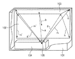
図1は、背面投射型表示装置を投射面背面から見た時の概略構造図である。つまり、装置の内側から見た構成を示している。
<Structure of rear projection display device>
FIG. 1 is a schematic structural diagram of a rear projection display device as viewed from the rear surface of the projection surface. That is, the configuration viewed from the inside of the apparatus is shown.
背面投射型表示装置の筐体101内において、光学系はおおまかに、投射ユニット104、全反射フレネルスクリーン102、天井ミラー103から構成されている。
In the
投射ユニット104から投射された光aは天井ミラー3で反射され、光bとしてスクリーン102に投射される。スクリーン102の四隅に対応する光も、それぞれ天井ミラーで反射されて、スクリーンに投射する。スクリーン102に投射した光は、後述のように、スクリーン102面を構成するプリズム内の全反射によって、ユーザの位置する方向に射出される。
Light a projected from the
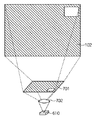
図2は、投射ユニット内部の概略構成を示した図である。 FIG. 2 is a diagram showing a schematic configuration inside the projection unit.
投射ユニット104は、光源である放電ランプ105を備えている。また、ダイクロックミラー201、ミラー202、PBS(偏光ビームスプリッタ)203、LCOSパネル207〜209、クロスダイクロプリズム204、レンズ205を備えている。そして、これらの光学系において、オフアキシャル光学系206を備えている。
The
投射型表示装置に用いられる光源としては、その効率、短アーク長などの理由から、高圧水銀ランプやメタルハライドランプなどの放電ランプ105が多く用いられている。これら放電ランプ105に対し電圧を印加することにより、水銀蒸気などによる高輝度な光が得られる。
As a light source used in a projection display device, a
光源105からの光は、ダイクロイックミラー201にて、RGB各色に分離される。図では、201aによってR+Gの光とBの光を分離し、201bによってRの光とGの光を分離している。分離されたRGBそれぞれの光は、PBS(偏光ビームスプリッタ)203を介してLCOSパネル207,208,209に入射される。
Light from the
LCOSパネル207〜209は、RGB各色毎の映像信号に応じて駆動されており、映像信号に応じた反射光が再びPBS203を通過し、クロスダイクロプリズム204に入射される。クロスダイクロプリズム204に入射したRGBそれぞれの光(映像)は、当該クロスダイクロプリズム204により合成され、レンズ205やオフアキシャル光学系206を経由して、天井ミラー103に向けて投射される。なお、ここで、光軸をずらしたオフアキシャル光学系206を採用することで、先の全反射フレネルスクリーン102と組み合わせた際の、スクリーン102上での中心部と周辺部との輝度差を低減可能としつつ装置の薄型を達成することが出来る。
The
図3は、投射ユニットからの光がスクリーンに投射される様子を模式的に示した図である。図3の白抜き矢印が、スクリーン102に投射される映像光の光路を示している。そして、後述するように、この映像光の大部分はスクリーン102の前面(図面の左方向)、つまりユーザの位置する方向に向かうことになる。
FIG. 3 is a diagram schematically showing how the light from the projection unit is projected onto the screen. A white arrow in FIG. 3 indicates an optical path of the image light projected on the
ただし、微小ながら図3の黒色の矢印で示されるような反射光が微量に存在する。この反射光は、フレネルスクリーン102の装置内部側の表面で反射する光である。スクリーンの材質、表面処理などにもよるが、入射光のうちの1〜5%の光が、反射光としてスクリーンと反対側に出てくることになる。
However, there is a minute amount of reflected light as indicated by the black arrow in FIG. This reflected light is light reflected from the surface of the
図4は、全反射フレネルスクリーン102の中心から動径方向に切断した際の断面の一部を拡大した図である。スクリーン102の装置内部側の表面はプリズム状になっている。なお、図4において断面左側はアクリル樹脂などで構成されるスクリーン102であり、断面右側は装置内部の空間(空気)となっている。
FIG. 4 is an enlarged view of a part of a cross section when cut in the radial direction from the center of the total
プリズムは、天井ミラー103からの光bを、鑑賞方向であるcに向けて全反射するようその頂点角度が決定されている。プリズムの入射面401がスクリーン面となす角をθs、プリズムの頂角をθt、光線bのスクリーン面に対する入射角をαとすると、光線bのプリズム面401に対する入射角θiは、
θi=α−θs (式1)
と表すことが出来る。
The vertex angle of the prism is determined so that the light b from the
θi = α−θs (Formula 1)
Can be expressed as
また、入射面401で屈折されて出射する光線b’の出射角θrは、プリズムの材料の屈折率をnとすると、
SIN(θr)=SIN(θi)/n (式2)
と表すことができる。したがって、光線b’の全反射面402への入射角θzは、
θz=θt−θr (式3)
となり、全反射させるための臨界角(n=1.49のとき42.16°)以上となるようにθtを選ぶ必要がある。全反射された出射光線cの方向がスクリーン面に垂直になる条件は、
θz=180°−θt−θs (式4)
と表すことが出来る。そのため、(式1)、(式2)、(式3)を用いて整理すると
TANθs=(SINα+nSIN2θt)/(COSα−nCOS2θt) (式5)
と表される。
Further, the emission angle θr of the light beam b ′ refracted and emitted from the
SIN (θr) = SIN (θi) / n (Formula 2)
It can be expressed as. Therefore, the incident angle θz of the light ray b ′ to the
θz = θt−θr (Formula 3)
Therefore, it is necessary to select θt so as to be equal to or greater than the critical angle for total reflection (42.16 ° when n = 1.49). The condition that the direction of the totally reflected outgoing light beam c is perpendicular to the screen surface is as follows:
θz = 180 ° −θt−θs (Formula 4)
Can be expressed as Therefore, when rearranged using (Expression 1), (Expression 2), and (Expression 3), TANθs = (SINα + nSIN2θt) / (COSα−nCOS2θt) (Expression 5)
It is expressed.
すなわち、プリズム(フレネルスクリーン)の材料としてアクリル樹脂(n=1.49)を用い、θt=58°として、α=72.97°とした場合、θs=67.60°、θz=54.40°となる。 That is, when an acrylic resin (n = 1.49) is used as a material of the prism (Fresnel screen), θt = 58 °, α = 72.97 °, θs = 67.60 °, θz = 54.40. °.
また、上記の式は画面内の任意の位置で成り立つことから、αの最小値と最大値についても同様に、n=1.49、θt=58°としてθs、θzを求めると、
αmin=65.22°のときθs=64.49°、θz=57.51°。また、αmax=78.19°のときθs=69.69°、θz=52.31°となる。
In addition, since the above equation is established at an arbitrary position in the screen, similarly for the minimum value and the maximum value of α, when θs and θz are obtained with n = 1.49 and θt = 58 °,
When αmin = 65.22 °, θs = 64.49 ° and θz = 57.51 °. When αmax = 78.19 °, θs = 69.69 ° and θz = 52.31 °.
したがって、θtを一定にしたまま、α=65.22°から78.19°に対して(式5)によって求まるθsとなるよう、θsを64.49°から69.69°まで徐々に変化させる。このようにして求められる角度となるよう、スクリーン102表面に形成される同心円状のプリズム群を構成することで、全画面範囲にわたって出射光線の方向をスクリーンに対して垂直とすることができる。
Therefore, with θt kept constant, θs is gradually changed from 64.49 ° to 69.69 ° so that θs obtained by (Equation 5) can be obtained with respect to α = 65.22 ° to 78.19 °. . By configuring the concentric prism group formed on the surface of the
ところで、前述したように、プリズムの入射面401においては、透過光線b’だけでなく、反射光線dが微量ながら生じる。この反射光線dの光量はプリズムの屈折率1.49の場合、反射率は約4%程度である。なお、仮に、この光線が天井ミラー103に反射して再びスクリーン102方向に戻ってしまうと表示画面上のゴーストとして観察されてしまう。そのため、スクリーン102の方向に反射されないよう、θtの値を選択する必要がある。
As described above, on the
図5は、フレネルスクリーン102の背面、つまり装置内側から観察したフレネルスクリーンの同心円の状態を例示的に示す図である。
FIG. 5 is a view exemplarily showing a concentric state of the Fresnel screen observed from the back of the
上述したように、スクリーン102の表面に形成されるプリズム群は、スクリーン102の全域で入射光bが全反射するように、同心円状に構成されている。ただし、その同心円の中心は本体の光軸からずれた位置に設定されている。これは、天井ミラー103からの光をユーザの鑑賞位置の中央方向に向けるためである。
As described above, the prism group formed on the surface of the
ところで、スクリーン102上に形成されるプリズム群が同心円状に構成されているため、図4で示したスクリーン102からの反射光dは、結果的に特定の集光領域300に集光されることになる。プリズム角度にも依存するが、本実施形態の構成においては、おおむねスクリーン102裏面位置に、スクリーン102全体からの反射光が集光されることになる。
By the way, since the prism group formed on the
<映像信号処理>
図6は、映像信号の処理の流れを示すブロック図である。おおまかに、映像入力回路601、ランプ制御回路602、パネル駆動回路603、補正回路607、制御部608、および、センサ609から構成される。
<Video signal processing>
FIG. 6 is a block diagram showing a flow of processing of the video signal. Roughly, it includes a
映像入力回路601は、外部から映像信号を入力し、解像度変換や、IP(インタレース−プログレッシブ)変換、色処理等の各種画像処理を行う回路である。
The
ランプ制御回路602は、放電ランプ105の点灯を制御する回路であり、高圧水銀ランプなどにおいてはバラスト電源などと呼ばれるものである。なお、放電ランプ105の替わりに、LEDを用いる場合は、この部分はLED駆動回路となる。
The
パネル駆動回路603は、前述したRGB各色に対応するLCOSパネル207〜209を駆動するための駆動回路である。
The
補正回路607は、パネル駆動回路603への映像信号供給にさいし、各色映像信号のガンマ特性などを補正する補正回路である。例えば、入力信号を、指定された補正量(補正係数)により決定されるマトリックス演算などを介して補正後の出力信号を得るよう構成される。なお、補正量は補正回路607内に配置される書き換え可能な記憶領域に記憶されている。
The
制御部608は、上記それぞれの回路を制御する制御部であり、CPU、RAMおよびROMなどから構成される。そして、CPUがROMに記憶されたプログラムを実行することにより各種制御が実現される。なお、ROMには各種制御プログラムのほか、各種パラメータが予め記憶されている。パラメータとしては、例えば、前述した補正回路607のマトリックス演算に用いられる補正値の初期値や、後述するホワイトバランスの基準パラメータが記憶されている。なお、ホワイトバランスの基準パラメータとして複数の色温度(例えば、5000K、6500K、9300Kの3つ)に対応した複数のパラメ−タを記憶するよう構成しても良い。また、制御部608をASICとして構成しても良い。
The
検出回路609は、図5において説明した、スクリーン102からの反射光dの集光領域300に配置された光センサ610からの信号を検出する検出回路であり、アナログ/デジタル(A/D)コンバータなどから構成されている。なお、A/Dコンバータなどが内蔵されたタイプのセンサを用いる場合などでは、制御部608と直接インタフェースすることも可能である。
The
次に、本発明での特徴的な部分である光センサ610について詳細に説明する。背景技術において説明したように、従来光センサを利用する場合は、スクリーン押さえ部分などにセンサを配し、拡大投影(オーバースキャン)した光の一部分を測定するように構成されていた。本発明においては、スクリーン102からの反射光dの集光領域300に光センサ610を配置する。そのようにすることで、スクリーン102の全面に対する映像光の状態を常時検出することが可能になる。
Next, the
スクリーン102からの反射光を検出するため、光の状態としては、光源自体のホワイトバランスずれ、LCOSの温度などによる透過率の変化、また、領域ごとのばらつきによる色むらなどによる影響を含むことができる。つまり、光センサ610による光の状態の検出結果に基づいて各種補正を施すことで、より高画質な表示装置を提供可能となる。
In order to detect the reflected light from the
なお、設置するセンサとしては、単一のフォトダイオードなどの点状のポイントセンサの他、CCDなどの線状のラインセンサ、または、CCD、CMOSなど平面のエリアセンサなどを用いることが出来る。そして、目的とする精度などに応じて適宜選択が可能である。 As a sensor to be installed, a point sensor such as a single photodiode, a linear line sensor such as a CCD, or a planar area sensor such as a CCD or CMOS can be used. And it can select suitably according to the target precision.
図7は、放電ランプ105の平均輝度レベルを測定する場合の光センサ610周辺の構成例を示す図である。ポイントセンサである光センサ610、スクリーン102からの反射光を拡散する拡散フィルタ701、拡散フィルタ701からの光をセンサ610に集光させるためのレンズ702である。また、拡散フィルタ701に対しスクリーン102全面からの反射光が入射するように構成している。このように構成することで、スクリーン102全体からの反射光は拡散され平均的な輝度として測定可能となる。なお、ここでセンサ610は、RGBを含む可視光域全域に感度を有している。
FIG. 7 is a diagram illustrating a configuration example around the
また、RGBすべてが合成された映像光に対する反射光を測定する他、RGB各色を時間をずらして順次表示することによりそれぞれの色の映像光に対する反射光を測定することが出来る。たとえば、RGBそれぞれの色における輝度レベルを測定することで、各色の輝度レベルを独立して検出することが出来る。そして、その輝度レベルに基づいて、各色それぞれに対応するLCOSの駆動条件を補正して制御する構成とすることにより、ホワイトバランスの補正が可能となる。駆動条件の補正方法としては、例えば、輝度レベルが高い色に対してはLCOSパネルによる反射光が少なくなるよう制御を行い、輝度レベルが低い色に対してはLCOSパネルによる反射光が多くなるように制御を行う方法がある。 In addition to measuring the reflected light with respect to the image light in which all of RGB are synthesized, it is possible to measure the reflected light with respect to the image light of each color by sequentially displaying each of the RGB colors while shifting the time. For example, by measuring the luminance level of each color of RGB, the luminance level of each color can be detected independently. The white balance can be corrected by adopting a configuration in which the driving condition of the LCOS corresponding to each color is corrected and controlled based on the luminance level. As a driving condition correction method, for example, control is performed so that light reflected by the LCOS panel is reduced for a color with a high luminance level, and light reflected by the LCOS panel is increased for a color with a low luminance level. There is a way to control.
上述のような可視光域全域に感度を有する単一の光センサによる構成の他、RGBそれぞれのフィルタ特性を持たせたセンサによる構成としても良い。なお、光センサ610がフィルタ無し、つまり、可視光域全域に感度を有する単一の光センサの場合には、R,G,Bそれぞれの映像光について切り替え表示を行い検出することとなる。一方、センサがR、G、B成分の輝度をそれぞれ独立して測定可能な複数のセンサから構成されている場合には、白色光、つまり、RGBすべてが合成された映像光について検出すればよい。なお、同一の色に対し、複数の異なる輝度の映像信号について輝度を検出することにより、各色の立ち上がり(γ曲線)についても補正を行うことが可能となる。
In addition to the configuration using a single optical sensor having sensitivity in the entire visible light region as described above, a configuration using a sensor having RGB filter characteristics may be used. In the case where the
・外来光の影響
一般的な鑑賞環境では、それほど強力な室内光の下で鑑賞されることは少ない。しかし、室内光、つまり、装置外部からの光がスクリーン102で散乱し、プリズムからの反射経路により入射することが考えられる。このような外来光の影響による上述の光センサによる検出への影響を軽減するために、測定に先立って、映像光がOFFの状態でのセンサへの入射光の測定を行っておくとよい。例えば、映像光OFF時の輝度レベルを基準として、上述の検出動作による検出輝度レベルとの差分を利用することで外来光の影響を軽減できることになる。
-Influence of extraneous light In a general viewing environment, it is rare to see under strong indoor light. However, it is conceivable that room light, that is, light from the outside of the apparatus is scattered by the
・輝度むら・色むら
LCOSパネルなどの液晶パネルでは、セルギャップなどのばらつきにより、各色のパネルごとに、部分的に輝度のムラが発生する場合がある。この輝度ムラによって、合成された映像光には色むらが発生することになる。
Luminance unevenness and color unevenness In a liquid crystal panel such as an LCOS panel, unevenness in luminance may occur partially for each color panel due to variations in cell gaps and the like. Due to this luminance unevenness, color unevenness occurs in the synthesized image light.
図8は、色むらを測定する様子を説明する図である。つまり、スクリーン102の一部領域に対して矩形などの所定のパターンを表示し輝度レベルを検出するよう構成する。そして、スクリーン102上でのパターンの表示領域を順次移動させ、領域毎に補正量を決定するのである。なお、パターン(領域の大きさ)は小さいほど、より空間解像度の高い検出が可能となるが、一般的にはスクリーン全領域に対する検出に時間がかかってしまうため、必要な空間解像度に応じて決定すると良い。なお、パターンが表示される領域毎に、光センサ610がフィルタ無し、つまり、可視光域全域に感度を有する単一の光センサの場合には、R,G,Bそれぞれの映像光について切り替え表示を行い検出することとなる。一方、センサがR、G、B成分の輝度をそれぞれ独立して測定可能な複数のセンサから構成されている場合には、白色光、つまり、RGBすべてが合成された映像光について検出すればよい。
FIG. 8 is a diagram for explaining how to measure color unevenness. That is, a predetermined pattern such as a rectangle is displayed on a partial area of the
スクリーン全領域の検出が終了したら、それぞれに領域毎に補正量を決定し、RAMやフラッシュメモリ等の記憶部に記憶する。そして、以後の画像表示の際に、この記憶部に記憶された補正量を基に領域毎に補正を行うようにすれば、輝度むら・色むらの補正が可能になる。 When the detection of the entire area of the screen is completed, a correction amount is determined for each area and stored in a storage unit such as a RAM or a flash memory. In the subsequent image display, if the correction is performed for each region based on the correction amount stored in the storage unit, it is possible to correct luminance unevenness and color unevenness.
<色むら補正の補正値導出の動作フロー>
図9は、色むら補正の補正量導出のフローチャートである。なお、以下の動作は、装置立ち上げ時に実行するよう構成しても良いし、ユーザによる任意の時点で実行するよう構成しても良い。なお、以下のフローにおいて、補正回路607は例えばROM等に記憶されたキャリブレーション用の補正量を用いて補正処理を行う。
<Operation flow for deriving correction values for uneven color correction>
FIG. 9 is a flowchart for deriving a correction amount for color unevenness correction. The following operations may be executed when the apparatus is started up, or may be executed at an arbitrary time by the user. In the following flow, the
ステップS901では、外部光の検出を行う。つまり前述したように、制御部608は、映像光がOFFの状態となるようにパネル駆動回路603に制御を行う。そして、制御部608は、その状態における光センサ610への入射光の測定を行う。なお、光センサ610による検出値は検出回路609を介してRAMなどに一時記憶される。
In step S901, external light is detected. That is, as described above, the
ステップS902では、制御部608は、輝度レベルの検出対象となる領域にパターン画像が表示されるようパネル駆動回路603を制御する。そして、制御部608は、その状態における光センサ610への入射光の測定を行う。なお、前述したように、可視光域全域に感度を有する単一の光センサの場合には、R,G,Bそれぞれの映像光について切り替え表示を行い検出する。一方、センサがR、G、B成分の輝度をそれぞれ独立して測定可能な複数のセンサから構成されている場合には、白色光、つまり、RGBすべてが合成された映像光について検出すればよい。
In step S <b> 902, the
ステップS903では、制御部608は、光センサ610による検出値を検出回路609を介して取得し、ステップS902でパターンを表示した領域の情報と関連付けてRAMなどに一時記憶する。
In step S903, the
ステップS904では、制御部608は、スクリーン102の全領域に対して検出処理(S902およびS903)が終了したか否かを判断する。終了していないと判断した場合はステップS905に進む。一方、全領域について終了していると判断した場合はステップS906に進む。
In step S904, the
ステップS905では、制御部608は、次の検出動作の対象となる領域を選択する。例えば、前回の領域と隣接し、まだ検出を行っていない部分を選択する。領域を選択後、ステップS902に戻る。
In step S905, the
ステップS906では、制御部608は、ステップS901で記憶した外部光の検出値とステップS903で記憶した各領域の検出値との差分を計算する。そして、ROMに記憶されたホワイトバランスの基準パラメータからのずれに対し、ずれが補償されるよう新たな補正量を決定する。なお、前述したように、補正量とは補正回路607で利用される例えばマトリックス演算における係数である。
In step S906, the
ステップS907では、制御部608は、ステップS906で決定された新たな補正量を補正回路607内の記憶領域に記憶する。
In step S907, the
このようなステップを経て、補正回路607内の記憶領域に新たなパラメータを記憶し当該パラメータを利用しマトリクス演算を行う。そうすることにより、スクリーン102に投影した映像光の状態を、スクリーン102全面に渡ってほぼ一定の状態に保つことが可能となる。つまり、補正回路607によるスクリーン102全面に渡る出力値は、制御部608内のROMに記憶したホワイトバランスの基準パラメータに対応した色温度に保たれることとなる。
Through these steps, a new parameter is stored in the storage area in the
なお、ここでは、補正回路607においてはマトリクス演算によるRGBの出力値の導出として説明を行った。しかし、3次元ルックアップテーブル(3D−LUT)、6軸補正、ガンマテーブル書き換えなどを用いた補正方法を利用して実現しても良い。また、出力値の導出にはソフトウェアによる演算の他、ハードウェア構成による導出を行っても良い。特に、補正量(補正係数)のみを制御部608から受け付け、演算部分はハードウェアにより構成することにより高速に補正処理を行うことが可能になる。
Here, the
また、上述の説明においては、スクリーン102からの反射光dの集光領域300に拡散フィルタ701を配置し、拡散フィルタ701により拡散された映像光をレンズ702で集光しポイントセンサにより輝度を検出するよう構成した。しかし、前述したようにセンサの構成はこれに限られるものではない。たとえば、集光領域300をカバーする2次元のエリアセンサを用い、直接領域毎の輝度の測定を行ってもよい。また、図10に示すように、集光領域300を横切るようラインセンサを走査し輝度を検出しても良い。エリアセンサやラインセンサを用いる構成とすることにより、ステップS905で説明したスクリーン102内の領域毎の輝度検出動作が不要となるというメリットがある。
In the above description, the
また、上述の説明においては、通常の表示動作とは独立したキャリブレーション動作として説明を行った。しかし、通常の動画や静止画の表示動作中に、映像信号から導出される全画面の平均輝度・ホワイトバランスと光センサ610で測定された平均輝度・ホワイトバランスとを比較し、ずれを検出しても良い。そして、平均輝度・ホワイトバランスずれが発生しているようであれば、ユーザに報知したり、上述したキャリブレーション動作に自動的に移行するよう構成しても良い。また、ずれ量から補正係数を導出して、その都度補正するように構成しても良い。この場合、ずれ量に対する補正値のテーブルなどをあらかじめ設定し、ずれ量から補正値を決定して、上述補正回路のマトリクスの補正係数を書き換えるなどして、補正することが可能である。
In the above description, the calibration operation is independent of the normal display operation. However, during normal video and still image display operations, the average luminance / white balance of the entire screen derived from the video signal is compared with the average luminance / white balance measured by the
さらに、上述の説明においては、背面投射装置の背面部分に集光領域300が存在するとした。しかし、もちろん、集光領域300が装置背面部分となる場合に限るものでない。例えば、天井ミラー103を用いず下方からスクリーン102に対して直接投射する場合、装置下部にスクリーン102からの反射光が集光する場合がある。その場合には、装置下部の集光領域300に光センサ610を設けるよう構成しても良い。つまり、スクリーン102からの反射光が集光する位置において測定を行うことで、鑑賞の邪魔にならず効率的な測定が可能となる。
Furthermore, in the above description, it is assumed that the
また、ここでは補正量導出の際の外光の影響を低減する方法について一部述べた。しかし、外光のホワイトバランス(色温度)を測定し、外光色をキャンセルするような色補正(色温度補正など)の補正量を導出するよう構成してもよい。そのように構成することで、外光に左右されない表示を行うことが可能になる。 Also, a part of the method for reducing the influence of external light when deriving the correction amount is described here. However, it may be configured to measure the white balance (color temperature) of the external light and derive a correction amount of color correction (color temperature correction or the like) that cancels the external light color. With such a configuration, it is possible to perform display independent of external light.
以上説明したとおり本実施形態によれば、スクリーン102からの反射光の集光領域300に光センサ610を設置する。そのような構成とすることにより、ユーザの鑑賞に影響を与えることなく表示全画面の光の変化の検出を可能となる。そして、その検出結果を元に補正回路607の動作を制御することで、より高画質な表示装置を提供することができる。
As described above, according to the present embodiment, the
(変形例)
上述した第1実施形態においては、スクリーン102からの反射光の集光領域に配置したセンサによる測定結果に基づいて、補正回路607の動作を制御するよう説明を行った。つまり、補正回路607の動作を制御することにより、LCOSパネル207〜209の駆動条件を制御しホワイトバランス補正を実現する構成として説明した。しかし、スクリーン102全面に対し同一の補正を行う時はLCOSパネル207〜209を制御する替わりに光源の駆動条件を制御するよう構成しても良い。つまり、検出回路609による出力に基づいて制御部608はランプ制御回路602へ制御を行うよう構成しても良い。
(Modification)
In the first embodiment described above, the description has been given to control the operation of the
近年では、光源として、放電ランプの変わりに、LEDランプを用いた各種装置が提案されている。そのため、今後LEDの高輝度化の進展によって、LEDを光源とした背面投射型表示装置が市場に出てくることは想像に難くない。しかしながら、LEDの輝度は駆動電流にしたがって変化するが、その値は素子毎にばらついている。そのため、LEDを光源として用いた場合には、LEDの輝度特性のばらつきが大きな問題となりうる。この場合には、ランプ制御回路602へ制御を行いRGB各色LEDの順方向電流をそれぞれ補正することで、ばらつきを補正することが可能となる。このように、スクリーン102全面に同一のバラツキが発生するずれを補正する場合には、ランプ制御回路602へ制御を行う構成が適している。
In recent years, various devices using LED lamps as light sources instead of discharge lamps have been proposed. For this reason, it is not difficult to imagine that rear projection display devices using LEDs as light sources will appear on the market as the brightness of LEDs increases. However, the luminance of the LED changes according to the driving current, but the value varies from element to element. For this reason, when an LED is used as a light source, variations in luminance characteristics of the LED can be a serious problem. In this case, it is possible to correct the variation by controlling the
なお、上述したランプ制御回路602への制御による補正は経時変化にも対応することが可能である。このときには、LCOSパネルに代表されるライトバルブの駆動補正を行うよう構成してもよいし、ランプの駆動補正を行うよう構成しても良い。あるいは、これら双方を組み合わせて補正してもよい。
Note that the correction by the control to the
(他の実施形態)
以上、本発明の実施形態について詳述したが、本発明は、複数の機器から構成されるシステムに適用しても良いし、また、一つの機器からなる装置に適用しても良い。
(Other embodiments)
Although the embodiments of the present invention have been described in detail above, the present invention may be applied to a system constituted by a plurality of devices or may be applied to an apparatus constituted by one device.
なお、本発明は、前述した実施形態の機能を実現するプログラムを、システム或いは装置に直接或いは遠隔から供給し、そのシステム或いは装置が、供給されたプログラムコードを読み出して実行することによっても達成される。従って、本発明の機能処理をコンピュータで実現するために、コンピュータにインストールされるプログラムコード自体も本発明の技術的範囲に含まれる。 The present invention can also be achieved by supplying a program that realizes the functions of the above-described embodiments directly or remotely to a system or apparatus, and the system or apparatus reads and executes the supplied program code. The Accordingly, the program code itself installed in the computer in order to realize the functional processing of the present invention by the computer is also included in the technical scope of the present invention.
その場合、プログラムの機能を有していれば、オブジェクトコード、インタプリタにより実行されるプログラム、OSに供給するスクリプトデータ等、プログラムの形態を問わない。 In this case, the program may be in any form as long as it has a program function, such as an object code, a program executed by an interpreter, or script data supplied to the OS.
プログラムを供給するための記録媒体としては、例えば、フロッピー(登録商標)ディスク、ハードディスク、光ディスク(CD、DVD)、光磁気ディスク、磁気テープ、不揮発性のメモリカード、ROMなどがある。 Examples of the recording medium for supplying the program include a floppy (registered trademark) disk, a hard disk, an optical disk (CD, DVD), a magneto-optical disk, a magnetic tape, a nonvolatile memory card, and a ROM.
その他、プログラムの供給方法としては、クライアントコンピュータのブラウザを用いてインターネットのホームページに接続し、ホームページから本発明のコンピュータプログラムそのもの、もしくは圧縮され自動インストール機能を含むファイルをハードディスク等の記録媒体にダウンロードすることによっても供給できる。また、本発明のプログラムを構成するプログラムコードを複数のファイルに分割し、それぞれのファイルを異なるホームページからダウンロードすることによっても実現可能である。つまり、本発明の機能処理をコンピュータで実現するためのプログラムファイルを複数のユーザに対してダウンロードさせるWWWサーバも、本発明のクレームに含まれるものである。 As another program supply method, a client computer browser is used to connect to an Internet homepage, and the computer program itself of the present invention or a compressed file including an automatic installation function is downloaded from the homepage to a recording medium such as a hard disk. Can also be supplied. It can also be realized by dividing the program code constituting the program of the present invention into a plurality of files and downloading each file from a different homepage. That is, a WWW server that allows a plurality of users to download a program file for realizing the functional processing of the present invention on a computer is also included in the claims of the present invention.
また、本発明のプログラムを暗号化してCD−ROM等の記憶媒体に格納してユーザに配布し、所定の条件をクリアしたユーザに対し、インターネットを介してホームページから暗号化を解く鍵情報をダウンロードさせ、その鍵情報を使用することにより暗号化されたプログラムを実行してコンピュータにインストールさせて実現することも可能である。 In addition, the program of the present invention is encrypted, stored in a storage medium such as a CD-ROM, distributed to users, and key information for decryption is downloaded from a homepage via the Internet to users who have cleared predetermined conditions. It is also possible to execute the encrypted program by using the key information and install the program on a computer.
また、コンピュータが、読み出したプログラムを実行することによって、前述した実施形態の機能が実現される他、そのプログラムの指示に基づき、コンピュータ上で稼動しているOSなどが、実際の処理の一部または全部を行い、その処理によっても前述した実施形態の機能が実現され得る。 In addition to the functions of the above-described embodiments being realized by the computer executing the read program, the OS running on the computer based on the instruction of the program is a part of the actual processing. Alternatively, the functions of the above-described embodiment can be realized by performing all of them and performing the processing.
さらに、記録媒体から読み出されたプログラムが、コンピュータに挿入された機能拡張ボードやコンピュータに接続された機能拡張ユニットに備わるメモリに書き込まれた後、そのプログラムの指示に基づき、その機能拡張ボードや機能拡張ユニットに備わるCPUなどが実際の処理の一部または全部を行い、その処理によっても前述した実施形態の機能が実現される。 Furthermore, after the program read from the recording medium is written in a memory provided in a function expansion board inserted into the computer or a function expansion unit connected to the computer, the function expansion board or The CPU or the like provided in the function expansion unit performs part or all of the actual processing, and the functions of the above-described embodiments are realized by the processing.
Claims (7)
特定の集光領域に設けられた光センサと、
前記光センサによる測定結果に基づいて、前記ライトバルブを制御する制御手段と、
を備え、
前記フレネルスクリーンは、同心円状に形成されたプリズム群を有し、該プリズム群は、前記ライトバルブを介して前記フレネルスクリーンに投射された光の一部を反射して前記特定の集光領域に集光するように構成されている
ことを特徴とする背面投射型表示装置。 A rear projection display device that projects light projected from a light source onto a Fresnel screen via a light valve,
An optical sensor provided in a specific light collection area ;
Control means for controlling the light valve based on the measurement result of the optical sensor;
Equipped with a,
The Fresnel screen has a prism group formed concentrically, and the prism group reflects a part of the light projected on the Fresnel screen through the light valve to the specific condensing region. A rear projection display device configured to condense light .
特定の集光領域に設けられた光センサと、
前記光センサによる測定結果に基づいて、前記光源の駆動を制御する制御手段と、
を備え、
前記フレネルスクリーンは、同心円状に形成されたプリズム群を有し、該プリズム群は、前記ライトバルブを介して前記フレネルスクリーンに投射された光の一部を反射して前記特定の集光領域に集光するように構成されている
ことを特徴とする背面投射型表示装置。 In a rear projection display device that projects light projected from a light source onto a Fresnel screen via a light valve,
An optical sensor provided in a specific light collection area ;
Control means for controlling the driving of the light source based on the measurement result of the optical sensor;
Equipped with a,
The Fresnel screen has a prism group formed concentrically, and the prism group reflects a part of the light projected on the Fresnel screen through the light valve to the specific condensing region. A rear projection display device configured to condense light .
前記制御手段は前記複数のライトバルブをそれぞれ独立して制御し色むらの補正を行うことを特徴とする請求項1に記載の背面投射型表示装置。 The light valve is composed of a plurality of light valves corresponding to RGB light,
The rear projection display device according to claim 1, wherein the control unit independently controls the plurality of light valves to correct color unevenness.
特定の集光領域に設けられた光センサが、該位置の光量を測定する測定工程と、
制御手段が、前記測定工程による光量の測定結果に基づいて、前記ライトバルブを制御する制御工程と、
を含み、
前記フレネルスクリーンは、同心円状に形成されたプリズム群を有し、該プリズム群は、前記ライトバルブを介して前記フレネルスクリーンに投射された光の一部を反射して前記特定の集光領域に集光するように構成されている
ことを特徴とする制御方法。 A method for controlling a rear projection display device that projects light projected from a light source onto a Fresnel screen via a light valve,
A measurement process in which a photosensor provided in a specific light collection region measures the amount of light at the position;
A control step for controlling the light valve based on a measurement result of the light amount in the measurement step;
Including
The Fresnel screen has a prism group formed concentrically, and the prism group reflects a part of the light projected on the Fresnel screen through the light valve to the specific condensing region. A control method characterized by being configured to collect light .
Priority Applications (3)
| Application Number | Priority Date | Filing Date | Title |
|---|---|---|---|
| JP2006118442A JP4906390B2 (en) | 2006-04-21 | 2006-04-21 | Rear projection display device and control method and program for rear projection display device |
| US11/733,809 US8123364B2 (en) | 2006-04-21 | 2007-04-11 | Rear-projection type display comprising a light measurement unit to measure reflected light from a fresnel screen |
| CN200710098240XA CN101060637B (en) | 2006-04-21 | 2007-04-20 | Rear-projection type display apparatus, and control method for rear-projection type display apparatus |
Applications Claiming Priority (1)
| Application Number | Priority Date | Filing Date | Title |
|---|---|---|---|
| JP2006118442A JP4906390B2 (en) | 2006-04-21 | 2006-04-21 | Rear projection display device and control method and program for rear projection display device |
Publications (3)
| Publication Number | Publication Date |
|---|---|
| JP2007292890A JP2007292890A (en) | 2007-11-08 |
| JP2007292890A5 JP2007292890A5 (en) | 2009-06-04 |
| JP4906390B2 true JP4906390B2 (en) | 2012-03-28 |
Family
ID=38619141
Family Applications (1)
| Application Number | Title | Priority Date | Filing Date |
|---|---|---|---|
| JP2006118442A Expired - Fee Related JP4906390B2 (en) | 2006-04-21 | 2006-04-21 | Rear projection display device and control method and program for rear projection display device |
Country Status (3)
| Country | Link |
|---|---|
| US (1) | US8123364B2 (en) |
| JP (1) | JP4906390B2 (en) |
| CN (1) | CN101060637B (en) |
Families Citing this family (30)
| Publication number | Priority date | Publication date | Assignee | Title |
|---|---|---|---|---|
| JP5294544B2 (en) * | 2006-05-08 | 2013-09-18 | キヤノン株式会社 | Rear projection display |
| KR101466119B1 (en) * | 2008-04-03 | 2014-11-27 | 삼성전자 주식회사 | Display apparatus and light control method of the same |
| US8125163B2 (en) | 2008-05-21 | 2012-02-28 | Manufacturing Resources International, Inc. | Backlight adjustment system |
| JP2010107779A (en) * | 2008-10-30 | 2010-05-13 | Sanyo Electric Co Ltd | Projection type image display |
| EP2396964A4 (en) * | 2009-02-16 | 2013-02-20 | Mri Inc | Display characteristic feedback loop |
| US8441574B2 (en) * | 2009-02-16 | 2013-05-14 | Manufacturing Resources International, Inc. | Visual identifier for images on an electronic display |
| CN102118419B (en) | 2009-12-30 | 2014-07-16 | 华为技术有限公司 | Method, device and communication system for transmitting picture information |
| KR20190130079A (en) | 2011-09-23 | 2019-11-20 | 매뉴팩처링 리소시스 인터내셔널 인코포레이티드 | System and method for environmental adaptation of display characteristics |
| US9645386B2 (en) * | 2011-12-10 | 2017-05-09 | Dolby Laboratories Licensing Corporation | Calibration and control of displays incorporating MEMS light modulators |
| JP5968031B2 (en) * | 2012-04-17 | 2016-08-10 | 三菱電機株式会社 | Laser light source projector |
| TWI448731B (en) | 2012-05-10 | 2014-08-11 | Delta Electronics Inc | Projection apparatus for providing multiple viewing angle images |
| JP2015018051A (en) * | 2013-07-10 | 2015-01-29 | キヤノン株式会社 | Image projection device and image display system |
| US10319408B2 (en) | 2015-03-30 | 2019-06-11 | Manufacturing Resources International, Inc. | Monolithic display with separately controllable sections |
| US10607520B2 (en) | 2015-05-14 | 2020-03-31 | Manufacturing Resources International, Inc. | Method for environmental adaptation of display characteristics based on location |
| US10593255B2 (en) | 2015-05-14 | 2020-03-17 | Manufacturing Resources International, Inc. | Electronic display with environmental adaptation of display characteristics based on location |
| US10321549B2 (en) | 2015-05-14 | 2019-06-11 | Manufacturing Resources International, Inc. | Display brightness control based on location data |
| US10922736B2 (en) | 2015-05-15 | 2021-02-16 | Manufacturing Resources International, Inc. | Smart electronic display for restaurants |
| US10269156B2 (en) | 2015-06-05 | 2019-04-23 | Manufacturing Resources International, Inc. | System and method for blending order confirmation over menu board background |
| US10319271B2 (en) | 2016-03-22 | 2019-06-11 | Manufacturing Resources International, Inc. | Cyclic redundancy check for electronic displays |
| KR102204132B1 (en) | 2016-05-31 | 2021-01-18 | 매뉴팩처링 리소시스 인터내셔널 인코포레이티드 | Electronic display remote image verification system and method |
| WO2018009917A1 (en) | 2016-07-08 | 2018-01-11 | Manufacturing Resources International, Inc. | Controlling display brightness based on image capture device data |
| US10510304B2 (en) | 2016-08-10 | 2019-12-17 | Manufacturing Resources International, Inc. | Dynamic dimming LED backlight for LCD array |
| CN109410891B (en) * | 2017-08-17 | 2021-01-01 | 群创光电股份有限公司 | Display and operation method thereof |
| US10578658B2 (en) | 2018-05-07 | 2020-03-03 | Manufacturing Resources International, Inc. | System and method for measuring power consumption of an electronic display assembly |
| US10782276B2 (en) | 2018-06-14 | 2020-09-22 | Manufacturing Resources International, Inc. | System and method for detecting gas recirculation or airway occlusion |
| CN111338154B (en) * | 2020-03-09 | 2022-02-08 | Oppo广东移动通信有限公司 | Electrochromic light ring, drive circuit and camera |
| US11526044B2 (en) | 2020-03-27 | 2022-12-13 | Manufacturing Resources International, Inc. | Display unit with orientation based operation |
| CN113552760A (en) * | 2021-06-17 | 2021-10-26 | 华东师范大学 | Novel laser light source control display device |
| US11895362B2 (en) | 2021-10-29 | 2024-02-06 | Manufacturing Resources International, Inc. | Proof of play for images displayed at electronic displays |
| CN114979597A (en) * | 2022-05-27 | 2022-08-30 | 峰米(重庆)创新科技有限公司 | Projection picture control method, projection device, computer device, and storage medium |
Family Cites Families (10)
| Publication number | Priority date | Publication date | Assignee | Title |
|---|---|---|---|---|
| JP3027065B2 (en) * | 1992-07-31 | 2000-03-27 | 日本電信電話株式会社 | Display / imaging device |
| JP3113935B2 (en) | 1995-04-24 | 2000-12-04 | 株式会社アドバンスト・ディスプレイ | Projection display device |
| JPH09159983A (en) * | 1995-12-08 | 1997-06-20 | Mitsubishi Electric Corp | Projection type display device and multivision projection type display device |
| IL119259A (en) * | 1996-09-17 | 2000-12-06 | Comview Graphics Ltd | Electro-optical display apparatus and method of using same |
| JPH11242293A (en) | 1998-02-26 | 1999-09-07 | Sony Corp | Back projection type color projector |
| JP3939141B2 (en) | 2001-12-05 | 2007-07-04 | オリンパス株式会社 | Projection type image display system and color correction method thereof |
| JP2004013114A (en) * | 2002-06-11 | 2004-01-15 | Sony Corp | Projection display device |
| CN100449401C (en) * | 2002-11-26 | 2009-01-07 | 三菱电机株式会社 | Transmissive viewing screen and projective display |
| JP4411030B2 (en) * | 2003-07-22 | 2010-02-10 | キヤノン株式会社 | Projection display |
| US7196741B2 (en) * | 2003-10-15 | 2007-03-27 | Mitsubishi Digital Electronics America, Inc. | Automatic image convergence for projection television systems |
-
2006
- 2006-04-21 JP JP2006118442A patent/JP4906390B2/en not_active Expired - Fee Related
-
2007
- 2007-04-11 US US11/733,809 patent/US8123364B2/en not_active Expired - Fee Related
- 2007-04-20 CN CN200710098240XA patent/CN101060637B/en not_active Expired - Fee Related
Also Published As
| Publication number | Publication date |
|---|---|
| CN101060637B (en) | 2012-07-18 |
| US20070247594A1 (en) | 2007-10-25 |
| US8123364B2 (en) | 2012-02-28 |
| JP2007292890A (en) | 2007-11-08 |
| CN101060637A (en) | 2007-10-24 |
Similar Documents
| Publication | Publication Date | Title |
|---|---|---|
| JP4906390B2 (en) | Rear projection display device and control method and program for rear projection display device | |
| US7907790B2 (en) | Image correcting apparatus, projection system, image correcting method, and image correcting program | |
| JP4059271B2 (en) | Projection display | |
| JP4552986B2 (en) | Image display device | |
| US7530695B2 (en) | Projector | |
| JP2007079593A (en) | Projection type display and driving method therefor | |
| WO2005055598A1 (en) | Front-projection multi-projection display | |
| JP2008003270A (en) | Illuminator and projection-type image display device using the same | |
| US20050264762A1 (en) | Method and apparatus to enhance contrast ratio in projection system | |
| US7549757B2 (en) | Device and method for adjusting color wheel index | |
| JP4921023B2 (en) | Projection type display device and control method and program for projection type display device | |
| US8061853B2 (en) | Image display device having plurality of light modulation devices, position change unit, and control unit and display position adjustment system and method | |
| JPH04367189A (en) | White balance adjuster | |
| JP2006171683A (en) | Sensor unit and image display device | |
| JP2009036884A (en) | Projection-type display device and display method | |
| JP2000028988A (en) | Liquid crystal projector | |
| WO2000057245A1 (en) | Projection system and projector | |
| JP2006251445A (en) | Projector, image display method and image display program | |
| JP2009058656A (en) | Image display device | |
| JP2008089836A (en) | Projector | |
| US7946718B2 (en) | System and method for optical calibration of a picture modulator | |
| JP3972708B2 (en) | Illumination apparatus, projection display apparatus, and driving method thereof | |
| JPH03226091A (en) | White balance adjustment device | |
| JP2004361500A (en) | Illuminator, projection display apparatus and its driving method | |
| JP2011176637A (en) | Projection type video display apparatus |
Legal Events
| Date | Code | Title | Description |
|---|---|---|---|
| A521 | Written amendment |
Free format text: JAPANESE INTERMEDIATE CODE: A523 Effective date: 20090420 |
|
| A621 | Written request for application examination |
Free format text: JAPANESE INTERMEDIATE CODE: A621 Effective date: 20090420 |
|
| A131 | Notification of reasons for refusal |
Free format text: JAPANESE INTERMEDIATE CODE: A131 Effective date: 20110922 |
|
| A521 | Written amendment |
Free format text: JAPANESE INTERMEDIATE CODE: A523 Effective date: 20111118 |
|
| TRDD | Decision of grant or rejection written | ||
| A01 | Written decision to grant a patent or to grant a registration (utility model) |
Free format text: JAPANESE INTERMEDIATE CODE: A01 Effective date: 20120106 |
|
| A01 | Written decision to grant a patent or to grant a registration (utility model) |
Free format text: JAPANESE INTERMEDIATE CODE: A01 |
|
| A61 | First payment of annual fees (during grant procedure) |
Free format text: JAPANESE INTERMEDIATE CODE: A61 Effective date: 20120110 |
|
| FPAY | Renewal fee payment (event date is renewal date of database) |
Free format text: PAYMENT UNTIL: 20150120 Year of fee payment: 3 |
|
| R151 | Written notification of patent or utility model registration |
Ref document number: 4906390 Country of ref document: JP Free format text: JAPANESE INTERMEDIATE CODE: R151 |
|
| FPAY | Renewal fee payment (event date is renewal date of database) |
Free format text: PAYMENT UNTIL: 20150120 Year of fee payment: 3 |
|
| LAPS | Cancellation because of no payment of annual fees |