JP4905657B2 - Security monitoring device, security monitoring system, and security monitoring method - Google Patents
Security monitoring device, security monitoring system, and security monitoring method Download PDFInfo
- Publication number
- JP4905657B2 JP4905657B2 JP2006143995A JP2006143995A JP4905657B2 JP 4905657 B2 JP4905657 B2 JP 4905657B2 JP 2006143995 A JP2006143995 A JP 2006143995A JP 2006143995 A JP2006143995 A JP 2006143995A JP 4905657 B2 JP4905657 B2 JP 4905657B2
- Authority
- JP
- Japan
- Prior art keywords
- security
- risk
- asset
- monitoring
- information
- Prior art date
- Legal status (The legal status is an assumption and is not a legal conclusion. Google has not performed a legal analysis and makes no representation as to the accuracy of the status listed.)
- Expired - Fee Related
Links
- 238000012544 monitoring process Methods 0.000 title claims description 133
- 238000012806 monitoring device Methods 0.000 title claims description 44
- 238000000034 method Methods 0.000 title claims description 23
- 230000004044 response Effects 0.000 claims description 185
- 230000003068 static effect Effects 0.000 claims description 46
- 238000004458 analytical method Methods 0.000 claims description 45
- 238000012797 qualification Methods 0.000 claims description 35
- 230000035945 sensitivity Effects 0.000 claims description 19
- 238000005192 partition Methods 0.000 claims description 13
- 238000007726 management method Methods 0.000 description 123
- 230000008859 change Effects 0.000 description 23
- 238000004891 communication Methods 0.000 description 20
- 238000010586 diagram Methods 0.000 description 15
- 230000002159 abnormal effect Effects 0.000 description 14
- 239000011521 glass Substances 0.000 description 11
- 238000001514 detection method Methods 0.000 description 10
- 238000012545 processing Methods 0.000 description 9
- 238000004364 calculation method Methods 0.000 description 7
- 230000008569 process Effects 0.000 description 7
- 238000012502 risk assessment Methods 0.000 description 6
- 230000007423 decrease Effects 0.000 description 5
- 230000002123 temporal effect Effects 0.000 description 5
- 230000009467 reduction Effects 0.000 description 4
- 238000012795 verification Methods 0.000 description 4
- 230000006378 damage Effects 0.000 description 3
- 230000000694 effects Effects 0.000 description 3
- 238000011156 evaluation Methods 0.000 description 3
- 230000012447 hatching Effects 0.000 description 3
- 241000282412 Homo Species 0.000 description 2
- 238000007630 basic procedure Methods 0.000 description 2
- 239000002131 composite material Substances 0.000 description 2
- 238000011161 development Methods 0.000 description 2
- 230000018109 developmental process Effects 0.000 description 2
- 239000000284 extract Substances 0.000 description 2
- 230000008520 organization Effects 0.000 description 2
- 230000004043 responsiveness Effects 0.000 description 2
- 101100108293 Caenorhabditis elegans aex-4 gene Proteins 0.000 description 1
- 230000005856 abnormality Effects 0.000 description 1
- 230000005540 biological transmission Effects 0.000 description 1
- 230000003247 decreasing effect Effects 0.000 description 1
- 230000001815 facial effect Effects 0.000 description 1
- 230000007257 malfunction Effects 0.000 description 1
- 230000003287 optical effect Effects 0.000 description 1
- 238000010223 real-time analysis Methods 0.000 description 1
- 230000008439 repair process Effects 0.000 description 1
- 238000012552 review Methods 0.000 description 1
- 238000012546 transfer Methods 0.000 description 1
- 230000007704 transition Effects 0.000 description 1
- 210000003462 vein Anatomy 0.000 description 1
Images


Classifications
-
- G—PHYSICS
- G06—COMPUTING; CALCULATING OR COUNTING
- G06Q—INFORMATION AND COMMUNICATION TECHNOLOGY [ICT] SPECIALLY ADAPTED FOR ADMINISTRATIVE, COMMERCIAL, FINANCIAL, MANAGERIAL OR SUPERVISORY PURPOSES; SYSTEMS OR METHODS SPECIALLY ADAPTED FOR ADMINISTRATIVE, COMMERCIAL, FINANCIAL, MANAGERIAL OR SUPERVISORY PURPOSES, NOT OTHERWISE PROVIDED FOR
- G06Q10/00—Administration; Management
- G06Q10/04—Forecasting or optimisation specially adapted for administrative or management purposes, e.g. linear programming or "cutting stock problem"
-
- G—PHYSICS
- G06—COMPUTING; CALCULATING OR COUNTING
- G06Q—INFORMATION AND COMMUNICATION TECHNOLOGY [ICT] SPECIALLY ADAPTED FOR ADMINISTRATIVE, COMMERCIAL, FINANCIAL, MANAGERIAL OR SUPERVISORY PURPOSES; SYSTEMS OR METHODS SPECIALLY ADAPTED FOR ADMINISTRATIVE, COMMERCIAL, FINANCIAL, MANAGERIAL OR SUPERVISORY PURPOSES, NOT OTHERWISE PROVIDED FOR
- G06Q10/00—Administration; Management
- G06Q10/06—Resources, workflows, human or project management; Enterprise or organisation planning; Enterprise or organisation modelling
-
- G—PHYSICS
- G08—SIGNALLING
- G08B—SIGNALLING OR CALLING SYSTEMS; ORDER TELEGRAPHS; ALARM SYSTEMS
- G08B13/00—Burglar, theft or intruder alarms
- G08B13/18—Actuation by interference with heat, light, or radiation of shorter wavelength; Actuation by intruding sources of heat, light, or radiation of shorter wavelength
- G08B13/189—Actuation by interference with heat, light, or radiation of shorter wavelength; Actuation by intruding sources of heat, light, or radiation of shorter wavelength using passive radiation detection systems
- G08B13/194—Actuation by interference with heat, light, or radiation of shorter wavelength; Actuation by intruding sources of heat, light, or radiation of shorter wavelength using passive radiation detection systems using image scanning and comparing systems
- G08B13/196—Actuation by interference with heat, light, or radiation of shorter wavelength; Actuation by intruding sources of heat, light, or radiation of shorter wavelength using passive radiation detection systems using image scanning and comparing systems using television cameras
- G08B13/19697—Arrangements wherein non-video detectors generate an alarm themselves
-
- G—PHYSICS
- G08—SIGNALLING
- G08B—SIGNALLING OR CALLING SYSTEMS; ORDER TELEGRAPHS; ALARM SYSTEMS
- G08B29/00—Checking or monitoring of signalling or alarm systems; Prevention or correction of operating errors, e.g. preventing unauthorised operation
- G08B29/18—Prevention or correction of operating errors
- G08B29/20—Calibration, including self-calibrating arrangements
-
- G—PHYSICS
- G07—CHECKING-DEVICES
- G07C—TIME OR ATTENDANCE REGISTERS; REGISTERING OR INDICATING THE WORKING OF MACHINES; GENERATING RANDOM NUMBERS; VOTING OR LOTTERY APPARATUS; ARRANGEMENTS, SYSTEMS OR APPARATUS FOR CHECKING NOT PROVIDED FOR ELSEWHERE
- G07C9/00—Individual registration on entry or exit
- G07C9/20—Individual registration on entry or exit involving the use of a pass
Description
本発明は、資産のセキュリティを適切に確保するためにセキュリティの度合いを監視する装置、システム、および方法に関するものである。 The present invention relates to an apparatus, a system, and a method for monitoring the degree of security in order to appropriately secure the security of assets.
従来から企業等の団体では、情報、金銭、設備、商品、人等の資産を守るために、種々のセキュリティデバイスを導入して、セキュリティシステムを構築している。そして、資産を損なうリスクを評価して、適切な対策を講じるリスクマネジメントを実施している。資産を損なうリスクと資産を守るセキュリティは相反する関係にあるため、リスクに代えて、セキュリティを評価することもある。 2. Description of the Related Art Conventionally, organizations such as companies have built a security system by introducing various security devices in order to protect assets such as information, money, equipment, products, and people. Risk management that evaluates the risk of damaging assets and takes appropriate measures is implemented. Since the risk of damaging assets and the security to protect the assets are in conflict, security may be evaluated instead of risk.
例えば情報資産を守るセキュリティ対策と該対策を評価するセキュリティ評価装置として、下記の特許文献1および特許文献2に記載されているようなものがある。特許文献1では、システムを構成する機器とリスク分析手法をユーザに選択させ、選択された構成機器で起こり得る脅威と該脅威に対抗できるセキュリティポリシとを予め記憶されたデータベースから抽出し、選択されたリスク分析手法に基づいて、各脅威の発生可能性と損失の大きさに関する情報をユーザに入力させて、各脅威のリスクを算出し、該算出結果よりセキュリティポリシの優先度を決定している。そして、セキュリティポリシと優先度を一覧表示し、該セキュリティポリシの実施の有無をユーザに入力させて、実施状況を集計し、セキュリティ評価結果として表示している。特許文献2では、予め記憶された対策定義ファイルに示されている各対策のリスク低減率に基づいて、ユーザに選択されたリスク対策を実施することによる効果を示す対策充足率を算出して表示している。また、対策定義ファイルに示されている各対策のリスク低減率やコスト、およびユーザにより入力された情報資産の経済的価値を示すリスク額等に基づいて、リスク額の大きな情報資産から順に最適なセキュリティ対策を選択している。
For example, there are security measures for protecting information assets and security evaluation devices for evaluating the measures as described in
上述した従来のセキュリティ評価装置では、脅威の発生可能性や損失の大きさおよびリスク低減率等といったリスクに関する情報を、人が収集して定めて入力する必要があり、該入力内容のみに基づいてセキュリティやリスクの分析等が行われている。しかしながら、日常の業務運営中に当然起こる物や人の移動や増減等といった変化により、リスクに関する情報は変化し、該変化に即応して人がリスクに関する情報を収集して定めて入力することは非常に困難であるため、実際からずれたリスクに関する情報が入力されるおそれが大いにある。このように実際からずれたリスクに関する情報が入力されると、該入力内容のみに基づいて行われるセキュリティやリスクの分析等の結果も実際からずれたものとなるため、該結果が出力されても、セキュリティやリスクの状態を正確に認識することができず、適切な対策を講じることもできない。 In the above-described conventional security evaluation apparatus, it is necessary for humans to collect, determine, and input information on risks such as the possibility of occurrence of threats, the magnitude of loss and the risk reduction rate, and based on only the input contents Security and risk analysis are conducted. However, risk-related information changes due to changes such as things that naturally occur during daily business operations, movements of people, changes, etc., and it is not possible for humans to collect, define, and input risk-related information in response to such changes. Since it is very difficult, there is a great possibility that information regarding risks that are out of practice is input. When information on risks that deviate from the actual is input in this way, the results of security and risk analysis, etc., performed based only on the input contents also deviate from the actual, so even if the results are output , The state of security and risk cannot be accurately recognized, and appropriate measures cannot be taken.
本発明は、上記課題を解決するものであって、その目的とするところは、セキュリティやリスクの状態を正確に認識して、適切な対策を講じることが可能なセキュリティ監視装置、セキュリティ監視システム、およびセキュリティ監視方法を提供することにある。 The present invention solves the above-mentioned problems, and the object of the present invention is to provide a security monitoring device, a security monitoring system capable of accurately recognizing the state of security and risk and taking appropriate measures, And providing a security monitoring method.
本発明に係るセキュリティ監視装置は、セキュリティデバイスと接続された、資産のセキュリティを監視するセキュリティ監視装置であって、セキュリティデバイスからの情報をリアルタイムに監視および収集する監視収集手段と、脅威から資産を保護する度合いを表す管理定数が、セキュリティデバイスの設定状態と対応して記録されたセキュリティ管理定数テーブルと、監視収集手段により監視および収集した情報と、セキュリティ管理定数テーブルの管理定数とに基づいて、資産の安全度または危険度を定量的に算出し、過去の算出値から現在の算出値までを時系列的に追跡することにより、資産に対するセキュリティリスク変動を分析および予測する分析予測手段と、分析予測手段により分析および予測した結果を出力する出力手段と、セキュリティデバイスを制御する制御手段とを備えている。「セキュリティリスク変動」とは、守るべき資産の安全度または危険度の変動のことである。制御手段は、分析予測手段が分析および予測した結果に基づいて、対策の必要性を判断し、対策が必要と判断した場合は、セキュリティデバイスの感度や認証レベルなどの設定状態を変更することにより、資産に対するセキュリティ強度を高める。 A security monitoring apparatus according to the present invention is a security monitoring apparatus that monitors the security of an asset connected to a security device, and monitors and collects information from the security device in real time, and an asset from a threat. Based on the security management constant table recorded corresponding to the setting state of the security device, the information monitored and collected by the monitoring collection means, and the management constant of the security management constant table Analytical prediction means for analyzing and predicting security risk fluctuations for assets by quantitatively calculating the safety level or risk level of the asset and tracking the past calculated value to the current calculated value in time series, and analysis Output means for outputting the results analyzed and predicted by the prediction means And a control means for controlling the security device. “Security risk fluctuation” is a change in the degree of safety or risk of assets to be protected. The control means determines the necessity of countermeasures based on the results analyzed and predicted by the analysis prediction means, and if it determines that countermeasures are necessary, it changes the settings of security devices such as sensitivity and authentication level. , Increase the strength of security for assets.
また、本発明に係るセキュリティ監視システムは、セキュリティデバイスと、該セキュリティデバイスに接続された上記のセキュリティ監視装置とから成るセキュリティ監視システムである。 The security monitoring system according to the present invention, a security device, Ru security monitoring system der consisting of connected said security monitoring devices to the security device.
さらに、本発明に係るセキュリティ監視方法は、上記のセキュリティ監視装置により、セキュリティデバイスにかかわるセキュリティを監視するセキュリティ監視方法であって、監視収集手段が、セキュリティデバイスからの情報をリアルタイムに監視および収集し、分析予測手段が、監視収集手段により監視および収集した情報と、セキュリティ管理定数テーブルの管理定数とに基づいて、資産の安全度または危険度を定量的に算出し、過去の算出値から現在の算出値までを時系列的に追跡することにより、資産に対するセキュリティリスク変動を分析および予測し、出力手段が、分析予測手段により分析および予測された結果を出力し、制御手段が、分析予測手段により分析および予測された結果に基づいて、対策の必要性を判断し、対策が必要と判断した場合は、セキュリティデバイスの感度や認証レベルなどの設定状態を変更することにより、資産に対するセキュリティ強度を高める。 Furthermore, a security monitoring method according to the present invention is a security monitoring method for monitoring security related to a security device by the above security monitoring device , wherein the monitoring and collecting means monitors and collects information from the security device in real time. Based on the information monitored and collected by the monitoring and collecting means and the management constants in the security management constant table, the analysis prediction means quantitatively calculates the safety level or risk level of the asset, and calculates the current value from the past calculated value. By tracking up to the calculated value in time series, the security risk fluctuation for the asset is analyzed and predicted, the output means outputs the result analyzed and predicted by the analysis prediction means, and the control means is analyzed by the analysis prediction means Based on the analysis and predicted results, determine the need for countermeasures and It is If it is deemed necessary, by changing the setting state of sensitivity and authentication level security devices, increasing the security level for the asset.
上記のようにすると、セキュリティ監視装置で自動的に、セキュリティデバイスからの情報をリアルタイムに監視および収集し、該情報に基づいてセキュリティリスク変動を分析および予測して、該結果を出力するので、従来の装置のように人により入力された情報のみに基づいてセキュリティやリスクの分析等を行って結果を出力するよりも、出力結果を実際に即したものにすることができる。このため、上記出力結果より、日常の業務運営中でのセキュリティやリスクの状態を正確に認識して、適切な対策を講じることが可能となる。 With the above configuration, the security monitoring device automatically monitors and collects information from the security device in real time, analyzes and predicts security risk fluctuations based on the information, and outputs the results. The output result can be made more realistic than the result of outputting the result by performing security or risk analysis based only on the information input by a person as in the apparatus of FIG. For this reason, from the output result, it is possible to accurately recognize the security and risk states during daily business operations and take appropriate measures.
また、本発明の一実施形態では、上記セキュリティ監視装置において、制御手段は、セキュリティデバイスに対するアクセス資格、またはセキュリティ区画を変化させる。「セキュリティ区画」とは、セキュリティを確保および監視する対象の範囲のことであって、空間的な場所の範囲に限らず、情報通信的な範囲等も含む。 In one embodiment of the present invention, in the security monitoring apparatus, the control means changes the access qualification for the security device or the security partition. The “security section” refers to a range of objects to be secured and monitored, and includes not only a spatial place range but also an information communication range.
上記のようにすると、セキュリティ監視装置で自動的に、セキュリティリスク変動の分析および予測の結果に基づいて、セキュリティ強度を適切に変化させて、所定の安全性を確保することができる。また、セキュリティデバイスに対するアクセス資格を厳しく制限させることにより、該セキュリティデバイスのアクセス資格にかかわるセキュリティ強度を高めることができる。さらに、セキュリティ区画を拡げて階層化することにより、該セキュリティ区画のセキュリティ強度を高めることができる。 As described above, the security monitoring apparatus can automatically change the security strength appropriately based on the analysis and prediction results of the security risk fluctuation to ensure predetermined safety . Also, by severely limiting access credentials to the security device, it is possible to enhance the security strength relating to access rights of the security device. Furthermore, the security strength of the security partition can be increased by expanding the security partition into a hierarchy.
また、本発明の一実施形態では、上記セキュリティ監視装置において、監視収集手段は、セキュリティデバイスの設定状態とセキュリティデバイスに対するアクセス回数とを監視および収集し、分析予測手段は、該設定状態とアクセス回数に基づいてセキュリティリスク変動を分析および予測する。この一例として分析予測手段は、セキュリティデバイスの設定状態に対応する管理定数をセキュリティ管理定数テーブルから読み出し、当該管理定数に基づいて静的リスク対応力を算出し、上記アクセス回数に基づいて動的リスク対応力を算出し、該静的リスク対応力および動的リスク対応力を乗算して総合的リスク対応力を算出する。「リスク対応力」とは、リスクと対立する狭義のセキュリティの度合いのことであって、セキュリティデバイスの導入により構築したセキュリティシステムによって、資産を脅かす脅威から資産を保護する度合いのことである。このうち、セキュリティデバイスの導入と設定により脅威から資産を保護する度合いが「静的リスク対応力」であり、セキュリティシステムの運用状態や運用制度や利用者のモラルにより脅威から資産を保護する度合いが「動的リスク対応力」である。そして、この静的リスク対応力と動的リスク対応力とから算出したのが「総合的リスク対応力」である。 In one embodiment of the present invention, in the security monitoring apparatus, the monitoring collection unit monitors and collects the setting state of the security device and the number of accesses to the security device, and the analysis prediction unit includes the setting state and the number of accesses. Analyze and predict security risk fluctuations based on As an example of this, the analysis predicting means reads the management constant corresponding to the setting state of the security device from the security management constant table , calculates the static risk response based on the management constant , and calculates the dynamic risk based on the access count. The response capability is calculated, and the overall risk response capability is calculated by multiplying the static risk response capability and the dynamic risk response capability. “Risk responsiveness” refers to the degree of security in a narrow sense that conflicts with risk, and is the degree to which an asset is protected from threats that threaten the asset by a security system constructed by introducing a security device. Of these, the degree to which assets are protected from threats through the introduction and configuration of security devices is “static risk response capability”, and the degree to which assets are protected from threats by the operational status of the security system, the operation system, and user morals. “Dynamic risk response capability”. The “total risk response capability” is calculated from the static risk response capability and the dynamic risk response capability .
上記のようにすると、多面的にセキュリティリスク変動を分析および予測して、出力した結果からセキュリティやリスクの状態を正確かつ詳細に認識することができる。また、静的リスク対応力、動的リスク対応力、総合的リスク対応力、およびリスクの発生頻度を算出して出力すると、これらの状態を定量的に認識して、これらのいずれかにかかわるどういった対策が必要なのかが判断し易くなり、必要な対策を迅速かつ適切に講じることができる。 As described above, it is possible to analyze and predict security risk fluctuations from various angles, and to accurately and precisely recognize the state of security and risk from the output results. In addition, when static risk response capability, dynamic risk response capability, overall risk response capability, and the frequency of occurrence of risk are calculated and output, these states are quantitatively recognized and It is easy to determine whether such measures are necessary, and necessary measures can be taken quickly and appropriately.
また、本発明の一実施形態では、上記セキュリティ監視装置において、分析予測手段は、監視収集手段により監視および収集した情報と、資産データベースまたはユーザの入力より取得した資産価値とに基づいて、セキュリティリスク変動を分析および予測する。 In one embodiment of the present invention, in the security monitoring apparatus, the analysis prediction unit is configured to perform security risk based on the information monitored and collected by the monitoring collection unit and the asset value acquired from the asset database or user input. Analyze and predict variability.
このようにすると、リアルタイムに監視および収集したセキュリティデバイスからの情報に基づいて、リスクの発生頻度を算出し、さらに該発生頻度と資産価値とに基づいて、リスクを算出して、該リスクの状態を正確かつ定量的に認識することができる。 In this way, the occurrence frequency of the risk is calculated based on the information from the security device monitored and collected in real time, the risk is calculated based on the occurrence frequency and the asset value, and the state of the risk is calculated. Can be accurately and quantitatively recognized.
また、本発明の一実施形態では、上記セキュリティ監視装置において、分析予測手段は、各資産の固有の識別子であるIDの情報に基づいて取得した資産数量と、資産データベースまたはユーザの入力より取得した単位数量当たりの資産価値とに基づいて、資産価値をリアルタイムに算出する。 In one embodiment of the present invention, in the security monitoring device, the analysis prediction unit acquires the asset quantity acquired based on ID information that is a unique identifier of each asset and the input from the asset database or the user. The asset value is calculated in real time based on the asset value per unit quantity.
このようにすると、セキュリティ監視装置で自動的に、資産価値を算出して、該資産価値と、リアルタイムに監視および収集したセキュリティデバイスからの情報とに基づいて、リスクを正確に算出して出力することができる。 In this way, the asset value is automatically calculated by the security monitoring device, and the risk is accurately calculated and output based on the asset value and information from the security device monitored and collected in real time. be able to.
また、本発明の一実施形態では、上記セキュリティ監視装置において、IDを記録した無線式のRFIDタグが各資産に付されており、監視収集手段は、RFIDタグを読み取るセキュリティデバイスからの読み取り情報をリアルタイムに監視および収集し、分析予測手段は、監視収集手段により監視および収集した上記読み取り情報に基づいて、資産数量をリアルタイムに検出する。 In one embodiment of the present invention, in the security monitoring device, a wireless RFID tag having an ID recorded is attached to each asset, and the monitoring and collecting unit reads information read from the security device that reads the RFID tag. Monitoring and collecting in real time, and the analysis predicting means detects the asset quantity in real time based on the read information monitored and collected by the monitoring and collecting means.
このようにすると、日常の業務運営中に資産の移動や増減等の変化が生じても、資産の位置と数量をリアルタイムに検出できる。そして、監視対象のセキュリティ区画にある現在の資産数量と単位数量当たりの資産価値とに基づいて、現在の資産価値を正確に算出することができる。 In this way, the position and quantity of assets can be detected in real time even if changes such as movement or increase / decrease of assets occur during daily business operations. Then, the current asset value can be accurately calculated based on the current asset quantity in the monitored security section and the asset value per unit quantity.
さらに、本発明の一実施形態では、上記セキュリティ監視装置において、監視対象のセキュリティ区画が階層化されている場合、監視収集手段は、各層にあるセキュリティデバイスからの情報をリアルタイムに監視および収集し、分析予測手段は、監視収集手段により監視および収集した情報に基づいて各層毎にリスク対応力を算出し、該各リスク対応力に基づいてセキュリティ区画全体のリスク対応力を算出する。 Furthermore, in one embodiment of the present invention, in the security monitoring device, when the security sections to be monitored are hierarchized, the monitoring and collecting means monitors and collects information from the security devices in each layer in real time, The analysis prediction unit calculates the risk response capability for each layer based on the information monitored and collected by the monitoring collection unit, and calculates the risk response capability of the entire security section based on the risk response capability.
このようにすると、階層化されたセキュリティ区画全体のリスクを算出することができる。また、階層化されたセキュリティ区画の各層および全体のリスク対応力とリスクの状態を正確かつ定量的に認識して、各層毎にまたは全体として必要な適切な対策を判断して講じることができる。 In this way, it is possible to calculate the risk of the entire hierarchized security section. In addition, it is possible to accurately and quantitatively recognize the risk response capability and risk state of each layer and the entire security division, and to determine and take appropriate measures for each layer or as a whole.
本発明によれば、セキュリティ監視装置で自動的に、セキュリティリスク変動のリアルタイムな分析および予測を行って、実際に即した結果を出力するので、日常の業務運営中でのセキュリティやリスクの状態を正確に認識して、適切な対策を講じることが可能となる。 According to the present invention, the security monitoring apparatus automatically performs real-time analysis and prediction of security risk fluctuations and outputs actual results, so the security and risk status during daily business operations can be checked. It is possible to recognize accurately and take appropriate measures.
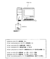
図1は、本発明の実施形態に係るセキュリティ監視システム100の構成を示す図である。セキュリティ監視システム100は、例えば企業で保有している情報、金銭、設備、商品、人等の資産を守るセキュリティを監視するために、企業で運用されている。セキュリティ監視システム100は、セキュリティ監視装置1、上位のセキュリティデバイスであるセキュリティ管理装置2、および下位のセキュリティデバイス3から構成されている。
FIG. 1 is a diagram showing a configuration of a security monitoring system 100 according to an embodiment of the present invention. The security monitoring system 100 is operated in a company in order to monitor security for protecting assets such as information, money, equipment, products, and people held in the company, for example. The security monitoring system 100 includes a
セキュリティ監視装置1は、パーソナルコンピュータ等で構成されている。セキュリティ監視装置1は、例えば屋内にある管理室等に設置されている。セキュリティ監視装置1は、セキュリティ管理装置2と電気的に接続され、セキュリティ管理装置2を介してセキュリティデバイス3と電気的に接続されている。制御部11は、CPUとメモリ等から成る。表示部12は、CRTまたはLCD等のディスプレイから成る。操作部13は、マウスとキーボードから成る。通信部14は、モデムと公知のインターフェイス回路等から成る。読書部15は、公知の磁気ディスク、光ディスク、またはメモリカード等の情報記録媒体に対して情報の読み書きを行うドライブやカードリーダ等から成る。記憶部16は、メモリとハードディスクから成る。
The
記憶部16には、制御部11が各部を制御するための種々のプログラムとデータが記憶されている。そのうち、セキュリティ監視AP16aは、セキュリティを監視して、セキュリティやリスクの状態を「見える化」する(視覚的に認識させる)アプリケーションプログラムである。セキュリティ監視DB16bは、セキュリティ監視AP16aの実行中に登録されかつ利用する情報を集めたデータベースである。セキュリティリスクログ16cは、セキュリティ監視AP16aの実行中に取得したセキュリティやリスクに関する情報を記録している。セキュリティ設定ログ16dは、セキュリティ監視AP16aの実行中に変更したセキュリティに関する設定情報を記録している。制御部11は、セキュリティ監視AP16aを実行し、該セキュリティ監視AP16aに従って、所定の情報を表示部12に表示し、操作部13により入力されたセキュリティを監視するための情報をセキュリティ監視DB16bに格納して登録する。また、制御部11は、セキュリティ監視AP16aに従って、後述するようにセキュリティを監視する。
The
セキュリティ管理装置2は、パーソナルコンピュータから成るクライアントとサーバとから構成されている。セキュリティ管理装置2は、例えば屋内にある管理室等に設置されている。セキュリティ管理装置2は、セキュリティ監視装置1および下位のセキュリティデバイス3に含まれる複数の装置4〜9とそれぞれ電気的に接続されている。図1では、セキュリティ管理装置2は1台しか示されていないが、例えば各装置4〜9等と対応するように複数台設けられている場合もある。制御部21、表示部22、操作部23、通信部24、読書部25、および記憶部26の構成は、上述した制御部11、表示部12、操作部13、通信部14、読書部15、および記憶部16と同様である。
The
記憶部26には、制御部11が各部を制御するための種々のプログラムとデータが記憶されている。そのうち、資産管理AP26aは、保有している資産を管理するためのアプリケーションプログラムである。資産DB26bは、資産管理AP26aの実行中に登録された資産に関する情報(例えば名称、種類、数量、価値、保有している位置、割り当てたID等)を集めたデータベースである。個人・ID管理AP26cは、従業員等の個人と、該個人に割り当てられたIDとを管理するためのアプリケーションプログラムである。個人・IDDB26dは、個人・ID管理AP26cの実行中に登録された個人の属性とIDに関する情報(例えば名前、所属、性別、経歴、バイオメトリクス情報、割り当てたID等)を集めたデータベースである。
The
ポリシ管理AP26eは、制定したセキュリティポリシを管理するためのアプリケーションプログラムである。セキュリティポリシとしては、例えばセキュリティ区画やセキュリティデバイス2、3等の設備に関する取極め、セキュリティ区画に対する人の入退に関する取極め、またはパーソナルコンピュータ等の情報設備やデータベース等の情報資産に対するアクセスに関する取極め等がある。セキュリティ区画とは、セキュリティを確保および監視する対象の範囲のことであって、空間的な場所の範囲に限らず、情報通信的な範囲等も含む。ポリシDB26fは、ポリシ管理AP26eの実行中に登録されたセキュリティポリシに関する情報(例えばセキュリティ区画の位置、セキュリティデバイス2、3の位置、入退資格、アクセス資格等)を集めたデータベースである。カメラDB26gは、下位のセキュリティデバイス3のカメラ監視装置5で撮影した監視映像のデータを集めたデータベースである。イベントDB26hは、下位のセキュリティデバイス3の各装置4〜9等により検出した出来事に関する情報を集めたデータベースである。これらの他にも、記憶部26には、下位のセキュリティデバイス3の各装置4〜9等を管理するためのプログラム等がある。記憶部26の各DB26b、26d、26f〜26h等に格納されている情報は、セキュリティ監視AP16aの実行中に利用される。
The policy management AP 26e is an application program for managing the established security policy. Security policies include, for example, arrangements for equipment such as security zones and
下位のセキュリティデバイス3には、侵入検知装置4、カメラ監視装置5、入退制御装置6、本人認証装置7、アクセス制御装置8、および警報・通報装置9等といった種々のセキュリティを確保するための複数の装置が含まれている。これらの各装置4〜9等は、セキュリティを確保したい現場等に設置されている。そのうち、侵入検知装置4は、コントローラ41とセンサ42等から構成されている。センサ42は、人の侵入や侵入可能な異常状態等を検知する。コントローラ41は、センサ42の検知結果をセキュリティ管理装置2へ送信する。カメラ監視装置5は、コントローラ51と監視用のカメラ52等から構成されている。カメラ52は、現場の様子を撮影する。コントローラ51は、カメラ52で撮影した映像をセキュリティ管理装置2へ送信する。
The
入退制御装置6は、コントローラ61とIDリーダ62と電子錠63等から構成されている。電子錠63は、現場の出入口に設置されたドア等を施解錠する。IDリーダ62は、個人が所持している非接触ICカード等の記録媒体に記録されている個人のID、または資産に付されたIDタグ等の記録媒体に記録されている資産のIDを読み取る装置である。コントローラ61は、IDリーダ62により読み取った個人のIDと、セキュリティ管理装置2により送信されて設定された入退資格者のIDとを照合して、一致するか否かを判定し、該判定結果に基づいて電子錠63を制御して、ドアからの入退を許可または禁止する。また、コントローラ61は、入退状況、IDリーダ62および電子錠63の動作状況、およびIDリーダ62により読み取ったID等の情報を入退ログ61aに記録し、セキュリティ管理装置2へ送信する。さらに、コントローラ61は、IDリーダ62により読み取った資産のIDをセキュリティ管理装置2へ送信する。本人認証装置7は、コントローラ71とバイオリーダ72等から構成されている。バイオリーダ72は、個人の指紋、手のひらの静脈、虹彩、顔画像、または声紋等のバイオメトリクス情報を読み取る装置である。コントローラ71は、バイオリーダ72により読み取ったバイオメトリクス情報と、セキュリティ管理装置2により送信されて設定された認証対象者のバイオメトリクス情報とを照合して、一致するか否かを判定し、該判定結果に基づいて認証対象者本人であることの認証または不認証を行って、セキュリティ管理装置2等へ出力する。
The entrance /
アクセス制御装置8は、クライアント81とサーバ82等から構成されている。クライアント81は、個人が使用するパーソナルコンピュータから成る。クライアント81とサーバ82はネットワークで接続されている。クライアント81は、該クライアント81、該クライアント81に格納されているバイオスやアプリケーションプログラムやファイル、サーバ82、サーバ82に格納されているデータベースやファイル等にアクセスするために入力されたユーザ名、パスワード、およびID等の情報と、セキュリティ管理装置2から送信されて設定されたアクセス資格者のユーザ名、パスワード、およびID等の情報とを照合して、一致するか否かを判定し、該判定結果に基づいて上記アクセス先へのアクセスを許可または禁止する。また、クライアント81は、上記アクセス先へのアクセス状況と、入力されたユーザ名、パスワード、およびID等の情報とをアクセスログ81aに記録し、セキュリティ管理装置2へ送信する。警報・通報装置9は、コントローラ91とアラーム92と警告灯93等から構成されている。コントローラ91は、セキュリティ管理装置2からの指令を受信して、アラーム92または警告灯93により警告を発したり、警備員やセキュリティ担当者が所持する図示しない端末装置に通報を発信したりする。
The
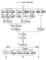
図2は、セキュリティ監視装置1で実行されるセキュリティ監視処理の基本手順を示すフローチャートである。このセキュリティ監視処理は、制御部11がセキュリティ監視AP16aに従って実行する。先ず、制御部11は、セキュリティを監視する条件を設定する(ステップS1)。具体的には、例えば資産、セキュリティ区画、セキュリティデバイス、リスクの種類、時期等といった監視対象を特定する情報を、ユーザに操作部13により入力させ、該入力情報に基づいて制御部11で条件を設定する。また、例えば予め監視対象を列挙して、該監視対象を特定する情報と監視順序をセキュリティ監視DB16bに登録しておき、該登録内容に基づいて制御部11で自動的に条件を設定するようにしてもよい。
FIG. 2 is a flowchart showing a basic procedure of security monitoring processing executed by the
次に、制御部11は、監視条件に基づいてセキュリティデバイス2、3からのセキュリティ情報や資産情報をリアルタイムに監視および収集する(ステップS2)。具体的には、例えば制御部11が通信部14により、監視条件にかかわるセキュリティに関する情報や資産に関する情報を送信させる指令をセキュリティ管理装置2に送信する。すると、セキュリティ管理装置2の制御部21が、資産DB26bやポリシDB26f等を検索して、該DBから監視条件にかかわるセキュリティ情報や資産情報を読み出し、通信部24によりセキュリティ監視装置1へ送信する。また、制御部21が資産DB26bやポリシDB26f等を検索して、監視条件にかかわるセキュリティデバイス3を特定し、該セキュリティデバイス3にセキュリティ情報等を送信させる指令を送信する。すると、監視条件にかかわるセキュリティデバイス3の設定情報やセキュリティデバイス3での取得情報等がセキュリティ情報として、セキュリティデバイス3からセキュリティ管理装置2を介してセキュリティ監視装置1へ送信される。これにより、制御部11はセキュリティデバイス2、3からのセキュリティ情報や資産情報をリアルタイムに監視および収集可能となる。制御部11と通信部14は、本発明における監視収集手段の一実施形態を構成する。
Next, the control unit 11 monitors and collects security information and asset information from the
次に、制御部11は、監視および収集したセキュリティ情報や資産情報と、セキュリティ監視DB16bに格納されている情報とに基づいて、セキュリティリスク変動を分析および予測する(ステップS3)。具体的には、例えば守るべき資産の安全度や危険度を定量的に算出して、予め設定された許容値と比較し、大きさを分析する。算出した値は、現在の算出値として、算出日時とともにセキュリティリスクログ16cに記録される。また、セキュリティリスクログ16cに同一の監視対象についての安全度や危険度の過去に算出した値が記録されていれば、該過去の算出値から現在の算出値までを時系列的に追跡し、変化傾向を分析して、今後の推移を予測する。制御部11は、本発明における分析予測手段の一実施形態を構成する。 Next, the control unit 11 analyzes and predicts the security risk fluctuation based on the monitored and collected security information and asset information and the information stored in the security monitoring DB 16b (step S3). Specifically, for example, the safety level and risk level of the assets to be protected are quantitatively calculated, compared with a preset allowable value, and the size is analyzed. The calculated value is recorded in the security risk log 16c as the current calculated value together with the calculation date. Further, if the security risk log 16c records a value calculated in the past for the safety level or the risk level for the same monitoring target, the past calculated value to the current calculated value is tracked in time series, Analyze change trends and predict future changes. The control part 11 comprises one Embodiment of the analysis prediction means in this invention.
次に、制御部11は、分析および予測した結果を出力する(ステップS4)。具体的には、例えば上記の算出値と許容値等をグラフ化して、表示部12に画像として表示する。これにより、ユーザはセキュリティやリスクの状態をリアルタイムに認識可能となる。制御部11と表示部12は、本発明における出力手段の一実施形態を構成する。また、例えば上記の結果を示す情報を電子メール等によりセキュリティ担当者等に送信するようにしてもよい。 Next, the control part 11 outputs the result analyzed and predicted (step S4). Specifically, for example, the calculated value and the allowable value are graphed and displayed on the display unit 12 as an image. Thereby, the user can recognize the state of security or risk in real time. The control part 11 and the display part 12 comprise one Embodiment of the output means in this invention. Further, for example, information indicating the above result may be transmitted to a security officer or the like by e-mail or the like.
次に、制御部11は、分析および予測した結果と、セキュリティ監視DB16bに格納されている情報とに基づいて、対策を判断および選択する(ステップS5)。具体的には、例えば制御部11が、上述した安全度や危険度の算出値と許容値とを比較して、セキュリティ強度を変える対策の必要性を判断する。ここで、算出値が許容値を超えていなければ、制御部11は対策が不要と判断する。対して、算出値が許容値を超えていれば、制御部11は対策が必要であると判断して、セキュリティ監視DB16bに予め登録されている対策候補の中から対策を選択する。そして、選択した対策がセキュリティデバイス2、3を制御することにより実行できる自動対策であれば、制御部11がセキュリティデバイス2、3を制御して、対策を実行し(ステップS6)、監視対象のセキュリティ強度を変化させる。さらに、対策を実行したことを表示部12に表示する等して通知し、該対策の内容と実行日時をセキュリティ設定ログ16dに記録する(ステップS7)。また、対策が必要であると判断した後、選択した対策が人手によらなければ実行できない手動対策であれば、制御部11は、該対策を実行すべきことを表示部12に表示する等して通知し、該対策の内容と該通知日時をセキュリティ設定ログ16dに記録する(ステップS8)。この後、上記の通知を受けたセキュリティ担当者等が対策を実行することにより、監視対象のセキュリティ強度が変化する。制御部11は、本発明における制御手段の一実施形態を構成する。
Next, the control unit 11 determines and selects a countermeasure based on the analysis and prediction result and the information stored in the security monitoring DB 16b (step S5). Specifically, for example, the control unit 11 compares the calculated values of safety and risk described above with allowable values, and determines the necessity of measures to change the security strength. Here, if the calculated value does not exceed the allowable value, the control unit 11 determines that no countermeasure is required. On the other hand, if the calculated value exceeds the allowable value, the control unit 11 determines that a countermeasure is necessary, and selects a countermeasure from the countermeasure candidates registered in advance in the security monitoring DB 16b. If the selected countermeasure is an automatic countermeasure that can be executed by controlling the
次に、制御部11はステップS9で、セキュリティの監視を終了するか否かを判断する。具体的には、例えばユーザが操作部13により監視を終了する指示を入力していれば、セキュリティの監視を終了すると判断して(ステップS9:YES)、処理を終了する。対して、ユーザが監視を終了する指示を入力していなければ、セキュリティの監視を終了しないと判断して(ステップS9:NO)、ステップS2へ移行して以降の処理を続行する。また、例えば時間やステップS2〜S9までの処理の実行回数に制限を設けて、セキュリティの監視を終了するか否かを判断するようにしてもよい。ステップS6で自動対策を実行した後に処理を続行した場合は、該対策の効果が以降のステップS2〜S5で表れて、認識可能となる。 Next, in step S9, the control unit 11 determines whether or not to end security monitoring. Specifically, for example, if the user inputs an instruction to end the monitoring through the operation unit 13, it is determined that the security monitoring is to be ended (step S9: YES), and the processing is ended. On the other hand, if the user has not input an instruction to end the monitoring, it is determined that the security monitoring is not ended (step S9: NO), and the process proceeds to step S2 and the subsequent processing is continued. Further, for example, it may be determined whether or not to end the security monitoring by setting a limit on the time and the number of execution times of the processes from steps S2 to S9. When the process is continued after the automatic countermeasure is executed in step S6, the effect of the countermeasure appears in the subsequent steps S2 to S5 and can be recognized.
図3は、図2のステップS4で出力されるセキュリティリスク変動の分析および予測結果の一例を示す図である。本図は、例えばセキュリティ監視装置1の表示部12に表示される。丸印で示す「破壊」や「個人情報漏洩」等は、あるセキュリティ区画で発生する可能性があるリスクの種類である。リスクの種類は、右上に示すように「自然」、「設備事故」、「情報通信」、「犯罪」、および「その他」の5つに分類されている。横軸は、各リスクの発生頻度を示している。リスクの発生頻度は、図2のステップS2で監視および収集されたセキュリティ情報等に基づいて算出され、「1」〜「5」の5つのクラスに分類されている。縦軸は、あるセキュリティ区画に存在する守るべき資産の価値であって、各リスクにより被害を受けたときに発生する損害額を示している。資産価値は、図2のステップS2で監視および収集された資産情報等に基づいて算出されている。各リスクは、発生頻度と資産価値の交差する位置にプロットされている。左上から右下へと斜めに延びる点線は、予め設定された許容値である。下方に縦線ハッチングで示している領域は、リスク受容領域である。左上にハッチング無しで示している領域は、リスク移転領域である。右上に横線ハッチングで示している領域は、リスク軽減/回避領域である。各リスクが許容値以下に位置するように対策を実施する。図2のステップS5で自動的に対策の必要性が判断されて、実施する対策が選択されるが、本図を見たセキュリティ担当者等もリスクの状態を認識して、対策の必要性を判断し、適切な対策を選択して実施する。
FIG. 3 is a diagram illustrating an example of analysis and prediction results of security risk fluctuation output in step S4 of FIG. This figure is displayed on the display unit 12 of the
以下、具体例を挙げて説明する。図4は、第1実施例のセキュリティ状況を示す図である。部屋Rは、企業のある事業所に設けられている。部屋Rの中には、守るべき金銭、設備、または商品等の物体資産A1がある。事業所の従業員数は、1,000人である。このうち、部屋Rに対する入退資格を有する入退資格者数は、100人である。またこの入退資格者数のうち、事業所で制定されたセキュリティの取り扱いに関する規約に合意したセキュリティ取り扱い合意数は、95人である。部屋Rへの侵入経路としては、窓W1、W2とドアDがある。窓W1、W2のガラス戸は、常時閉められて施錠されている。窓W1には、該窓W1のガラスの破壊を検知するガラスセンサ42aが設置されている。窓W2の傍には、該窓W2からの人の侵入を検知するパッシブセンサ42bが設置されている。両センサ42a、42bの検知感度は、現在「1」に設定されている。両センサ42a、42bは、図1の侵入検知装置4のセンサ42の一例である。つまり、部屋Rにはセキュリティシステムとして、センサ42a、42bを含む侵入検知装置4とセキュリティ管理装置2から成る侵入管理システムが導入されている。
Hereinafter, a specific example will be described. FIG. 4 is a diagram showing the security status of the first embodiment. The room R is provided in an office where a company is located. In the room R, there is an object asset A1 such as money, equipment or goods to be protected. The number of employees at the office is 1,000. Among these, the number of entrance / exit qualifiers who have entrance / exit qualifications for the room R is 100. In addition, among the number of qualified persons, there are 95 security handling agreements that have agreed to the security handling rules established at the establishment. As an intrusion route to the room R, there are windows W1 and W2 and a door D. The glass doors of the windows W1, W2 are always closed and locked. In the window W1, a glass sensor 42a for detecting breakage of the glass in the window W1 is installed. A passive sensor 42b that detects intrusion of a person from the window W2 is installed near the window W2. The detection sensitivity of both sensors 42a and 42b is currently set to “1”. Both sensors 42a and 42b are examples of the
ドアDは、常時閉められて電子錠63aにより施錠されている。ドアDの内側と外側の近傍には、個人が所持する図示しない非接触ICカードからIDを読み取るカードリーダ62a、62bが設置されている。電子錠63aおよびカードリーダ62a、62bは、図1の入退制御装置6の電子錠63およびIDリーダ62の一例である。カードリーダ62a、62bで読み取ったIDが、部屋Rに対する入退資格者のIDと一致すると、電子錠63aが開錠し、ドアDを開けて部屋Rに対して入退可能となる。カードリーダ62a、62bによる非接触ICカードのID認証レベル(例えば、カードリーダ62a、62bの通信感度や、IDの照合内容等のレベル)は、現在「2」に設定されている。ドアDの総操作回数(即ち、電子錠63aの総動作回数)は、1ヶ月当たり5,000回である。そのうちドアDの異常操作回数(即ち、電子錠63aで異常が生じた数)は、1ヶ月当たり100回である。つまり、部屋Rにはセキュリティシステムとして、カードリーダ62a、62bを含む入退制御装置6とセキュリティ管理装置2から成る入退管理システムが導入されている。ドアDの外側の近傍には、個人の指紋を読み取るバイオリーダ72aが設置されている。バイオリーダ72aは、図1の本人認証装置7のバイオリーダ72の一例である。つまり、部屋Rにはセキュリティシステムとして、バイオリーダ72aを含む本人認証装置7とセキュリティ管理装置2から成る本人認証システムが導入されている。なお、バイオリーダ72aによる本人認証は、現在行われていないものとする。
The door D is always closed and locked with an electronic lock 63a. In the vicinity of the inside and outside of the door D, card readers 62a and 62b for reading an ID from a non-contact IC card (not shown) possessed by an individual are installed. The electronic lock 63a and the card readers 62a and 62b are examples of the electronic lock 63 and the ID reader 62 of the entry /
図5は、第1実施例のセキュリティ監視処理の詳細手順を示すフローチャートである。本フローチャートは、図2のフローチャートにおける一部の処理の詳細を示している。つまり、図5のステップS2a〜S2gは、図2のステップS2の詳細を示し、図5のステップS3a〜S3mは、図2のステップS3の詳細を示し、図5のステップS5a〜S5fおよびS6b〜S6eは、図2のステップS5およびS6の詳細を示している。図5のステップS1、S4、S7、S8、S9はそれぞれ図2の同一符号のステップと同一である。 FIG. 5 is a flowchart showing a detailed procedure of the security monitoring process of the first embodiment. This flowchart shows details of part of the processing in the flowchart of FIG. That is, steps S2a to S2g in FIG. 5 show details of step S2 in FIG. 2, steps S3a to S3m in FIG. 5 show details of step S3 in FIG. 2, and steps S5a to S5f and S6b in FIG. S6e shows the details of steps S5 and S6 in FIG. Steps S1, S4, S7, S8, and S9 in FIG. 5 are the same as the steps having the same reference numerals in FIG.
図4の部屋Rの中にある物体資産A1のセキュリティを監視するために、ユーザがセキュリティ監視装置1でセキュリティ監視AP16aを起動させて、操作部13により監視条件を入力する。ここでは、セキュリティ区画として「部屋R」を、リスクの種類として例えば「盗難紛失」をそれぞれ入力する。すると、制御部11がこれらの入力情報を監視条件として設定し(図2のステップS1)、該監視条件に基づいてセキュリティデバイス2、3からのセキュリティ情報と資産情報をリアルタイムに監視および収集する(ステップS2)。詳しくは、セキュリティ管理装置2の資産DB26bには、部屋Rに物体資産A1があるという情報と、物体資産A1の資産価値の情報が登録されている。このため、制御部11は、物体資産A1の資産価値の情報がセキュリティ管理装置2から送信されて来るのを監視して、該情報を収集する(図5のステップS2g)。これ以外に、例えば物体資産A1の資産価値の情報を、ユーザに入力させるようにしてもよい。セキュリティ管理装置2の個人・IDDB26dとポリシDB26fには、脅威と成り得る数である従業員数、部屋Rに対する入退資格者数、および該入退資格者中のセキュリティ取り扱い合意数の情報がそれぞれ登録されている。このため、制御部11は、従業員数と入退資格者数とセキュリティ取り扱い合意数の情報がセキュリティ管理装置2から送信されて来るのを監視して、該情報を収集する(ステップS2d、S2f)。また、セキュリティ管理装置2のポリシDB26fには、部屋Rにセキュリティデバイス3として、侵入検知装置4のガラスセンサ42aおよびパッシブセンサ42bと、入退制御装置6のカードリーダ62a、62bとが設置されているという情報が登録されている。このため、制御部11は、現在の各センサ42a、42bの感度の情報が侵入検知装置4からセキュリティ管理装置2を介して送信されて来るのを監視して、該情報を収集する(ステップS2a、S2b)。また、制御部11は、カードリーダ62a、62bによる現在の非接触ICカードID認証レベルの情報が入退制御装置6からセキュリティ管理装置2を介して送信されて来るのを監視して、該情報を収集する(ステップS2c)。さらに、入退制御装置6の入退ログ61aには、現在までのドアDの総操作回数および異常操作回数の情報が記録されている。このため、制御部11は、現在までのドアDの総操作回数と異常操作回数の情報が入退制御装置6からセキュリティ管理装置2を介して送信されて来るのを監視して、該情報を収集する(ステップS2e)。
In order to monitor the security of the object asset A1 in the room R of FIG. 4, the user activates the security monitoring AP 16a with the
次に、制御部11は、監視および収集した上記のセキュリティ情報および資産情報と、セキュリティ監視DB16bに格納されている情報とに基づいて、セキュリティリスク変動を分析および予測する(図2ステップS3)。詳しくは、制御部11は、下記のように部屋Rの静的リスク対応力値、動的リスク対応力値、総合的リスク対応力値、リスクの発生頻度、およびリスク値をそれぞれ定量的に算出して、変化傾向を分析し、今後の推移を予測する。リスク対応力とは、リスクと対立する狭義のセキュリティの度合いのことであって、セキュリティデバイス2、3の導入により構築した入退管理等のセキュリティシステムによって、資産を脅かす脅威から資産を保護する度合いのことである。このうち、セキュリティデバイス2、3の導入と設定により脅威から資産を保護する度合いが静的リスク対応力であり、セキュリティシステムの運用状態や運用制度や利用者のモラルにより脅威から資産を保護する度合いが動的リスク対応力である。そして、この静的リスク対応力と動的リスク対応力とから算出したのが総合的リスク対応力である。リスクの発生頻度とは、脅威から資産を保護できずにリスクが発生する頻度のことである。
Next, the control unit 11 analyzes and predicts a security risk variation based on the security information and asset information monitored and collected and information stored in the security monitoring DB 16b (step S3 in FIG. 2). Specifically, the control unit 11 quantitatively calculates the static risk response power value, the dynamic risk response power value, the overall risk response power value, the risk occurrence frequency, and the risk value of the room R as described below. Then, analyze the trend of change and predict future changes. “Risk responsiveness” refers to the degree of security in a narrow sense that conflicts with risk, and the degree to which an asset is protected from threats that threaten the asset by a security system such as entry / exit management constructed by introducing
セキュリティ監視DB16bには、図6に示すセキュリティ管理定数テーブルの情報が登録されている。このセキュリティ管理定数テーブルは、セキュリティデバイス2〜9等を設置して所定の設定で動作させることにより脅威から資産を保護する度合い、つまり確保できる安全度を、「0〜1」までの数値である管理定数として示している。管理定数が大きい程、安全度は高い。図6では、以下の説明で必要なもののみ図示している。上述したように現在のパッシブセンサ42bとガラスセンサ42aの感度はともに「1」であり、現在の非接触ICカードID認証レベルは「2」である。このため、制御部11はセキュリティ管理定数テーブルから、現在のパッシブセンサ42bの感度「1」に対応する管理定数「0.90」、現在のガラスセンサ42aの感度「1」に対応する管理定数「0.90」、および現在の非接触ICカードID認証レベル「2」に対応する管理定数「0.95」をそれぞれ読み出す(図5のステップS3a、S3b、S3c)。そして、該管理定数から、下記のように部屋Rの静的リスク対応力値を算出する(ステップS3d)。
(部屋Rの静的リスク対応力)=(各侵入経路での静的リスク対応力)=(ドアDでの非接触ICカードID認証による管理定数)×(窓W1でのガラスセンサ42aによる管理定数)×(窓W2でのパッシブセンサ42bによる管理定数)=0.95×0.90×0.90=0.77
Information of the security management constant table shown in FIG. 6 is registered in the security monitoring DB 16b. This security management constant table is a numerical value from “0 to 1” indicating the degree of protection of assets from threats by installing
(Static risk response capability in room R) = (Static risk response capability in each intrusion route) = (Management constant by non-contact IC card ID authentication at door D) × (Management by glass sensor 42a in window W1) Constant) × (management constant by the passive sensor 42b in the window W2) = 0.95 × 0.90 × 0.90 = 0.77
また、制御部11は、従業員数、部屋Rに対する入退資格者数、ドアDの総操作回数、ドアDの異常操作回数、および入退資格者中のセキュリティ取り扱い合意数から、下記のように部屋Rに対する入退資格者比率、入退のための正常操作率、および入退資格者中のセキュリティ取り扱い合意比率をそれぞれ算出し(ステップS3e、S3f、S3g)、さらにこれらから、下記のように部屋Rの動的リスク対応力値を算出する(ステップS3h)。
(部屋Rに対する入退資格者比率)=(入退資格者数)/(従業員数)=100/1,000=0.1
(入退のための正常操作率)=(ドアDの総操作回数−ドアDの異常作回数)/(ドアDの総操作回数)=(5,000−100)/5,000=0.98
(入退資格者中のセキュリティ取り扱い合意比率)=(入退資格者中のセキュリティ取り扱い合意数)/(入退資格者数)=95/100=0.95
(部屋Rの動的リスク対応力)=(組織のモラルの元)+(組織のモラルの元の残数)×(1−部屋Rに対する入退資格者比率)×(入退のための正常操作率)×(入退資格者中のセキュリティ取り扱い合意比率)=0.1+0.9×(1−0.1)×0.98×0.95=0.85
上記の算出式において、組織のモラルの元とは、元来確保できる動的リスク対応力のことである。この組織のモラルの元を「0.1」、この残数を「0.9」と予め制定している。また、入退のための正常操作率としてドアDの正常操作率のみを考慮しているのは、他の侵入経路である窓W1、2は常時閉めきっていて開閉操作しないため、正常操作率を考慮する必要がないからである。なお、正常操作率を考慮する侵入経路が複数ある場合は、そのうち最低の正常操作率のみを入退のための正常操作率とすればよい。
Moreover, the control part 11 is as follows from the number of employees, the number of persons qualified for entrance / exit to the room R, the total number of operations of the door D, the number of abnormal operations of the door D, and the number of security handling agreements among qualified persons. Calculate the entrance / exit qualification ratio for room R, normal operation rate for entrance / exit, and security handling agreement ratio among entrance / exit qualification persons (steps S3e, S3f, S3g), and from these, as follows: The dynamic risk response power value of the room R is calculated (step S3h).
(Rate of entrance / exit qualification for room R) = (Number of entrance / exit qualifications) / (Number of employees) = 100 / 1,000 = 0.1
(Normal operation rate for entry / exit) = (Total number of operations of door D−Number of abnormal operations of door D) / (Total number of operations of door D) = (5,000−100) / 5,000 = 0. 98
(Agreement of security handling among qualified persons) = (Number of agreed security handling among qualified persons) / (Number of qualified persons) = 95/100 = 0.95
(Dynamic risk response capability of room R) = (Organizational moral element) + (Remaining number of organizational morality) × (1-Ratio of entrance / exit qualification for room R) × (Normal for entrance / exit) (Operation rate) x (Agreement of security handling among qualified persons) = 0.1 + 0.9 x (1-0.1) x 0.98 x 0.95 = 0.85
In the above calculation formula, the moral element of the organization is the dynamic risk response capability that can be secured originally. The moral element of this organization is established in advance as “0.1” and the remaining number as “0.9”. The reason why only the normal operation rate of the door D is considered as the normal operation rate for entering and exiting is that the windows W1 and W2, which are other intrusion routes, are always closed and are not opened and closed. It is because it is not necessary to consider. When there are a plurality of intrusion routes that take into account the normal operation rate, only the lowest normal operation rate may be used as the normal operation rate for entering and exiting.
また、制御部11は、上記の部屋Rの静的リスク対応力値と動的リスク対応力値から、下記のように部屋Rの総合的リスク対応力値を算出する(ステップS3i)。
(部屋Rの総合的リスク対応力値)=(部屋Rの静的リスク対応力値)×(部屋Rの動的リスク対応力値)=0.77×0.85=0.65
Moreover, the control part 11 calculates the comprehensive risk response power value of the room R from the static risk response power value and the dynamic risk response power value of the room R as described below (step S3i).
(Total risk response capability value of room R) = (Static risk response capability value of room R) × (Dynamic risk response capability value of room R) = 0.77 × 0.85 = 0.65
また、制御部11は、上記の総合的リスク対応力値から、下記のように部屋Rでの物体資産A1の盗難紛失のリスクの発生頻度を算出する(ステップS3j)。
(部屋Rでの物体資産A1の盗難紛失のリスクの発生頻度)=1−(部屋Rの総合的リスク対応力値)=1−0.65=0.35
Further, the control unit 11 calculates the occurrence frequency of the risk of the loss of the theft of the object asset A1 in the room R as described below from the above comprehensive risk response value (step S3j).
(Frequency of risk of theft loss of the object asset A1 in the room R) = 1− (total risk response capability value of the room R) = 1−0.65 = 0.35
さらに、制御部11は、上記のリスクの発生頻度と、セキュリティ管理装置2から収集した物体資産A1の資産価値から、下記のように部屋Rでの物体資産A1の盗難紛失のリスク値を算出する(ステップS3k)。
(部屋Rでの物体資産A1の盗難紛失のリスク値)=(部屋Rでの物体資産A1の盗難紛失のリスクの発生頻度)×(物体資産A1の資産価値)=0.35×(例えば1億円)=3,500万円
Further, the control unit 11 calculates the risk value of the loss of the theft of the object asset A1 in the room R from the risk occurrence frequency and the asset value of the object asset A1 collected from the
(Risk risk of loss of object asset A1 in room R) = (Frequency of risk of loss of theft of object asset A1 in room R) × (Asset value of object asset A1) = 0.35 × (eg 1 (Billion yen) = 35 million yen
上記のように算出すると、制御部11は、上記各算出値を現在の算出値として、セキュリティリスクログ16cに算出日時とともに記録する。そして、制御部11は、該現在の算出値を予め設定された許容値と比較して、大きさを分析する。また、制御部11は、セキュリティリスクログ16cに同一の監視対象についての安全度や危険度の過去に算出した値が記録されていれば、該過去の算出値から現在の算出値までを時系列的に追跡し、変化傾向を分析して、今後の推移を予測する。さらに、制御部11は、この分析および予測した結果をグラフ化して出力する(図2のステップS4)。 If it calculates as mentioned above, the control part 11 will record each said calculated value with the calculation date in the security risk log 16c as a present calculated value. Then, the control unit 11 analyzes the magnitude by comparing the present calculated value with a preset allowable value. In addition, if a previously calculated value of the safety level or the risk level of the same monitoring target is recorded in the security risk log 16c, the control unit 11 performs time series from the past calculated value to the current calculated value. Follow up and analyze change trends to predict future changes. Furthermore, the control part 11 graphs and outputs this analysis and the predicted result (step S4 in FIG. 2).
図7〜図12は、第1実施例のセキュリティリスク変動の分析および予測結果の一例を示す図である。各図は、例えばセキュリティ監視装置1の表示部12に表示される。図7は、部屋Rの静的リスク対応力値の時間的変化を示す図である。図8は、部屋Rの動的リスク対応力値の時間的変化を示す図である。図9は、部屋Rの総合的リスク対応力値の時間的変化を示す図である。図10は、部屋Rでの物体資産A1の盗難紛失のリスクの発生頻度の時間的変化を示す図である。図11は、部屋Rでの物体資産A1の盗難紛失のリスク値の時間的変化を示す図である。各図に示す細い実線はそれぞれ、静的リスク対応力値、動的リスク対応力値、総合的リスク対応力値、リスクの発生頻度、リスク値であり、点線は、それぞれの許容値である。図8〜図11に示す太い実線は、細い実線の一次近似線であり、二点鎖線は、該一次近似線を未来方向へ延ばした各値の予測線である。図7〜図9より、部屋Rでの物体資産A1の盗難紛失のリスク対応力、即ちセキュリティの変化状態が視覚的に認識できる。図10および図11より、部屋Rでの物体資産A1の盗難紛失のリスクの変化状態が視覚的に認識できる。図8〜図11の左側に見られる各値の突発的な変化は、部屋Rへの不審者の侵入や部屋Rでの事故やドアDの故障等が原因である。図8〜図11の右側に見られる各値の傾向的な変化は、物体資産A1の増加や従業員の増加等が原因である。一次近似線および予測線より、今後も該傾向的な変化が継続することが予測できる。図7〜図9では、各リスク対応力値がそれぞれ許容値以上であるのが良い。図10および図11では、発生頻度およびリスク値がそれぞれ許容値以下であるのが良い。
7 to 12 are diagrams illustrating examples of security risk fluctuation analysis and prediction results according to the first embodiment. Each figure is displayed on the display unit 12 of the
図12は、部屋Rでの物体資産A1の盗難紛失のリスクの状態を示す図である。本図の表示形式は、前述した図3と同様である。R1〜R3はそれぞれある時点における部屋Rでの物体資産A1の盗難紛失のリスクである。リスクの発生頻度は、「1」(1,000年に1回)〜「5」(1年に数回)の5つのクラスに分類されて、認識し易くなっている。図13は、リスクの発生頻度を5つのクラスに分類するための発生頻度クラステーブルである。この発生頻度クラステーブルの情報は、セキュリティ監視DB16bに登録されている。例えば、上述したように算出したリスクの発生頻度が0以上で0.1未満であれば、1,000年に1回発生するクラス「1」に分類される。図12より、部屋Rでの物体資産A1の盗難紛失のリスクの許容値に対する大きさと変化が視覚的に認識できる。例えばR1の時点では、リスクの発生頻度は「0.35」であり、物体資産A1の資産価値は「1億円」であり、リスクは許容値以下になっている。このR1の時点から、例えば従業員が増加して、リスクの発生頻度が上がると、R2の時点のように、リスクは許容値を上回ってしまう。 FIG. 12 is a diagram illustrating a state of risk of theft loss of the object asset A1 in the room R. The display format of this figure is the same as that of FIG. R1 to R3 are risks of theft loss of the object asset A1 in the room R at a certain point in time. The occurrence frequency of the risk is classified into five classes from “1” (once in 1,000 years) to “5” (several times in one year) to facilitate recognition. FIG. 13 is an occurrence frequency class table for classifying risk occurrence frequencies into five classes. Information on the occurrence frequency class table is registered in the security monitoring DB 16b. For example, if the risk occurrence frequency calculated as described above is 0 or more and less than 0.1, it is classified into the class “1” that occurs once in 1,000 years. From FIG. 12, the magnitude | size and change with respect to the allowable value of the risk of theft loss of the object asset A1 in the room R can be visually recognized. For example, at the time of R1, the occurrence frequency of the risk is “0.35”, the asset value of the object asset A1 is “100 million yen”, and the risk is below the allowable value. If, for example, the number of employees increases from the time R1 and the frequency of occurrence of the risk increases, the risk exceeds the allowable value as at the time R2.
上記のように分析および予測の結果を出力すると、制御部11は、該分析および予測の結果と、セキュリティ監視DB16bに格納されている情報とに基づいて、対策を判断および選択する(図2のステップS5および図5のステップS5a)。例えば、上述したように算出した静的リスク対応力値と動的リスク対応力値と総合的リスク対応力値のいずれもが許容値以上であり、かつリスクの発生頻度とリスク値のいずれもが許容値以下である場合には、制御部11は、部屋Rのセキュリティ強度を変える対策が不要と判断する。対して、静的リスク対応力値と動的リスク対応力値と総合的リスク対応力値のいずれかが許容値を下回った場合若しくはまもなく下回ることが予測された場合、またはリスクの発生頻度とリスク値のいずれかが許容値を上回った場合若しくはまもなく上回ることが予測された場合には、制御部11は、部屋Rのセキュリティ強度を変える対策が必要と判断し、セキュリティ監視DB16bを検索して、対策を選択する。 When the analysis and prediction results are output as described above, the control unit 11 determines and selects a countermeasure based on the analysis and prediction results and the information stored in the security monitoring DB 16b (FIG. 2). Step S5 and step S5a in FIG. For example, all of the static risk response power value, dynamic risk response power value, and overall risk response power value calculated as described above are equal to or greater than the allowable value, and both the occurrence frequency of risk and the risk value are When the value is equal to or smaller than the allowable value, the control unit 11 determines that a measure for changing the security strength of the room R is unnecessary. On the other hand, if any of the static risk response value, dynamic risk response value, or overall risk response value falls below or is expected to fall shortly after the allowable value, or the occurrence frequency and risk of the risk When any of the values exceeds the allowable value or is predicted to soon exceed, the control unit 11 determines that a countermeasure for changing the security strength of the room R is necessary, searches the security monitoring DB 16b, Select a countermeasure.
セキュリティ監視DB16bには、図14に示すセキュリティ対策候補テーブルの情報が登録されている。このセキュリティ対策候補テーブルは、制御部11がセキュリティデバイス2、3を制御することにより実行できる自動対策の候補と、人手によらなければ実行できない手動対策の候補を示している。例えば自動対策候補としては、センサ感度調整、認証レベル調整、認証内容調整、アクセス資格制限、セキュリティ区画調整等がある。認証内容調整とは、例えばカードID認証に加えて、バイオメトリクス情報による本人認証を行ったり、本人認証を1本の指の指紋情報から、複数本の指の指紋情報で行ったりする等のように、認証内容を変更することである。アクセス資格制限とは、例えばアクセス資格を開発課の全員に与えていたのを、開発課の課長のみにする等のように、アクセス資格を与える者を限定して、アクセス資格者数を減らすことである。アクセス資格は、データベース等に対してデータの読み出しや書き込みをする情報通信的なアクセス資格だけでなく、ある場所に対して進入や退出をする入退資格等も含む。手動対策候補としては、他のアクセス資格制限、他のセキュリティ区画調整、セキュリティデバイス増設、セキュリティデバイス修理・交換、資産移動、対策検討要請等がある。
Information of the security countermeasure candidate table shown in FIG. 14 is registered in the security monitoring DB 16b. This security countermeasure candidate table shows candidates for automatic countermeasures that can be executed by the control unit 11 controlling the
制御部11は、部屋Rのセキュリティ強度を高めるように、セキュリティ対策候補テーブルから実施可能な対策を抽出して、部屋Rのセキュリティ状況に合うように具体的に設定する。部屋Rにはセキュリティシステムとして、パッシブセンサ42bとガラスセンサ42aを含む侵入管理システム、カードリーダ62a、62bを含む入退管理システム、バイオリーダ72aを含む本人認証システムが導入されている。このため、自動対策として、パッシブセンサ42bの感度調整(図5のステップS5b)、ガラスセンサ42aの感度調整(ステップS5c)、非接触ICカードのID認証または指紋情報による本人認証の認証レベルや、該認証内容の調整(ステップS5d)、および部屋Rへの入退資格者制限(ステップS5e)をそれぞれ設定する。手動対策としては、セキュリティ対策候補テーブルに挙げられているその他の対策を設定する(ステップS5f)。そして、制御部11は、上記の算出値と許容値の差分の大きさに応じて、ステップS5b〜S5fの対策を1つまたは複数選択する。例えば、差分が微小であれば、自動対策のいずれかを1つだけ選択する。また、差分がある程度大きければ、自動対策の全て選択する。また、差分が著しく大きければ、手動対策を選択する。または、図2のステップS2〜S10が繰り返し実行されることを考慮して、例えば自動対策から1つずつ順番に選択して行くようにしてもよい。または、上記の設定した対策を表示部12に表示して、ユーザに操作部13により選択させるようにしてもよい。 The control unit 11 extracts measures that can be implemented from the security measure candidate table so as to increase the security strength of the room R, and specifically sets the measures to match the security status of the room R. In the room R, an intrusion management system including a passive sensor 42b and a glass sensor 42a, an entrance / exit management system including card readers 62a and 62b, and a personal authentication system including a bioreader 72a are introduced as security systems. Therefore, as an automatic measure, sensitivity adjustment of the passive sensor 42b (step S5b in FIG. 5), sensitivity adjustment of the glass sensor 42a (step S5c), authentication level of identity authentication of contactless IC card or personal authentication by fingerprint information, Adjustment of the authentication content (step S5d) and restriction on entry / exit to the room R (step S5e) are set. As the manual countermeasure, other countermeasures listed in the security countermeasure candidate table are set (step S5f). Then, the control unit 11 selects one or a plurality of measures in steps S5b to S5f according to the difference between the calculated value and the allowable value. For example, if the difference is small, only one of the automatic countermeasures is selected. If the difference is large to some extent, all automatic countermeasures are selected. If the difference is remarkably large, a manual measure is selected. Alternatively, in consideration of the repeated execution of steps S2 to S10 in FIG. 2, for example, the automatic measures may be selected one by one in order. Alternatively, the set countermeasure may be displayed on the display unit 12 so that the user can select it by the operation unit 13.
自動対策のパッシブセンサ42bやガラスセンサ42aの感度調整(ステップS5b、S5c)を選択した場合には、制御部11は、セキュリティ管理装置2を介して侵入検知装置4を制御し、センサ42a、42bの感度を現在設定されている「1」から、例えばより厳しい「2」に変更させる(ステップS6b、S6c)。また、非接触ICカードのID認証または指紋情報による本人認証の認証レベルや、該認証内容の調整(ステップS5d)を選択した場合には、制御部11は、セキュリティ管理装置2を介して入退制御装置6や本人認証装置7を制御し、例えばドアDからの部屋Rに対する入退時に非接触ICカードのID認証と指紋情報による本人認証を行わせる(ステップS6d)。この場合、ID認証と本人認証の両方ができたときにのみ、電子錠63a開錠して、部屋Rに対する入退を許可する。また、部屋Rへの入退資格者制限(ステップS5e)を選択した場合には、制御部11は、セキュリティ管理装置2や入退制御装置6を制御し、部屋Rへの入退資格者をより厳しく限定して、入退資格者数を現在設定されている「100人」から例えば「10人」に減少させる(ステップS6e)。上記のように自動対策を実行すると、制御部11は、上記自動対策を実行したことを表示部12に表示する等して通知し、該対策の内容と実行日時をセキュリティ設定ログ16dに記録する(図2のステップS7)。これにより、セキュリティ担当者等が後でセキュリティ設定ログ16dの記録内容を見て、自動的に実行された対策を確認可能となる。
When the sensitivity adjustment (step S5b, S5c) of the passive sensor 42b or the glass sensor 42a for automatic countermeasures is selected, the control unit 11 controls the
また、手動対策のその他の対策(図5のステップS5f)を選択した場合には、制御部11は、該対策を実行すべきことを表示部12に表示する等して通知し、該対策の内容と該通知日時をセキュリティ設定ログ16dに記録する(図2のステップS8)。この後、上記の通知を受けたセキュリティ担当者等が対策を実行することにより、監視対象のセキュリティ強度が変化する。 If another manual countermeasure (step S5f in FIG. 5) is selected, the control unit 11 notifies the display unit 12 that the countermeasure should be executed, for example, and notifies the countermeasure. The contents and the notification date / time are recorded in the security setting log 16d (step S8 in FIG. 2). Thereafter, the security person who receives the above notification executes the countermeasure, and the security strength of the monitoring target changes.
そして、制御部11は図2のステップS9で、例えば前述したようにセキュリティの監視を終了すると判断すれば(ステップS9:YES)、処理を終了し、監視を終了しないと判断すれば、(ステップS9:NO)、ステップS2へ移行して以降の処理を続行する。処理を続行する場合に、ステップS4で表示部12に表示した分析および予測結果を残しておいて、該表示に以降の分析および予測結果を追加するようにすると、各リスク対応力値、リスクの発生頻度、リスク値の変化から、セキュリティやリスクの状態をリアルタイムかつ時系列的に認識可能となる。 Then, in step S9 of FIG. 2, for example, if the control unit 11 determines that the security monitoring is ended (step S9: YES) as described above, the control unit 11 ends the process and determines that the monitoring is not ended (step S9). S9: NO), the process proceeds to step S2 and the subsequent processing is continued. When the processing is continued, if the analysis and prediction results displayed on the display unit 12 in step S4 are left and subsequent analysis and prediction results are added to the display, each risk response capability value, risk From changes in the occurrence frequency and risk value, it becomes possible to recognize the status of security and risk in real time and in time series.
上述したように図5のステップS6b〜S6eの自動対策を全て実行した後に、処理を続行した場合は、該対策の効果が以降のステップS2〜S5で直ぐに表れて、認識可能となる。つまり、次回のステップS2で制御部11は、センサ42a、42bの感度が「2」に変化したことをリアルタイムに監視および収集する(図5のステップS2a、S2b)。また、非接触ICカードのID認証レベルが「2」であることに加えて、指紋情報による本人認証が実施されて、該認証レベル(例えば、バイオメトリクス情報の照合の閾値等のレベル)が例えば「2」に設定されたことをリアルタイムに監視および収集する(ステップS2c)。また、従業員数は「1,000人」から変わらないが、入退資格者数と該入退資格者中のセキュリティ取り扱い合意数がともに例えば「10人」に変化したことをリアルタイムに監視および収集する(ステップS2d、S2f)。ドアDの総操作回数および異常操作回数と、物体資産A1の資産価値は変化していないので、前回と同一の総操作回数「5,000回/月」および異常操作回数「100回/月」と資産価値「1億円」をリアルタイムに監視および収集する(ステップS2e、S2g)。 As described above, when the processing is continued after executing all the automatic countermeasures in steps S6b to S6e in FIG. 5, the effect of the countermeasure immediately appears in the subsequent steps S2 to S5 and can be recognized. That is, in the next step S2, the control unit 11 monitors and collects in real time that the sensitivity of the sensors 42a and 42b has changed to “2” (steps S2a and S2b in FIG. 5). Further, in addition to the ID authentication level of the non-contact IC card being “2”, personal authentication is performed using fingerprint information, and the authentication level (for example, a level such as a threshold value for biometric information matching) is, for example, The fact that it is set to “2” is monitored and collected in real time (step S2c). In addition, the number of employees does not change from “1,000 people”, but monitoring and collecting in real time that both the number of qualifying employees and the number of security handling agreements among those qualifying persons have changed to, for example, “10”. (Steps S2d and S2f). Since the total number of operations and the number of abnormal operations of the door D and the asset value of the object asset A1 are not changed, the total number of operations “5,000 times / month” and the number of abnormal operations “100 times / month” are the same as the previous time. The asset value “100 million yen” is monitored and collected in real time (steps S2e, S2g).
そして、次回のステップS3で制御部11は、下記のように部屋Rの静的リスク対応力値、動的リスク対応力値、総合的リスク対応力値、リスクの発生頻度、およびリスク値をそれぞれ定量的に算出して、セキュリティリスク変動を分析および予測する。なお、部屋Rの静的リスク対応力値の算出にあたり、センサ42a、42bの感度はともに「2」であり、カードID認証および本人認証のレベルはともに「2」であるので、図6のセキュリティ管理定数テーブルより、センサ42a、42bに対応する管理定数は「0.95」、カードID認証+本人認証に対応する管理定数は「0.99」に変わっている。
(部屋Rの静的リスク対応力)=(ドアDでの非接触ICカードID認証+指紋情報による本人認証の管理定数)×(窓W1でのガラスセンサ42aによる管理定数)×(窓W2でのパッシブセンサ42bによる管理定数)=0.99×0.95×0.95=0.89
(部屋Rに対する入退資格者比率)=(入退資格者数)/(従業員数)=10/1,000=0.01
(入退のための正常操作率)=(ドアDの総操作回数−ドアDの異常作回数)/(ドアDの総操作回数)=(5,000−100)/5,000=0.98
(入退資格者中のセキュリティ取り扱い合意比率)=(入退資格者中のセキュリティ取り扱い合意数)/(入退資格者数)=10/10=1.0
(部屋Rの動的リスク対応力)=(組織のモラルの元)+(組織のモラルの元の残数)×(1−部屋Rに対する入退資格者比率)×(入退のための正常操作率)×(入退資格者中のセキュリティ取り扱い合意比率)=0.1+0.9×(1−0.01)×0.98×1.0=0.97
(部屋Rの総合的リスク対応力値)=(部屋Rの静的リスク対応力値)×(部屋Rの動的リスク対応力値)=0.89×0.97=0.86
(部屋Rでの物体資産A1の盗難紛失のリスクの発生頻度)=1−(部屋Rの総合的リスク対応力値)=1−0.86=0.14
(部屋Rでの物体資産A1の盗難紛失のリスク値)=(部屋Rでの物体資産A1の盗難紛失のリスクの発生頻度)×(物体資産A1の資産価値)=0.14×(例えば1億円)=1,400(単位:万円)
Then, in the next step S3, the control unit 11 sets the static risk response power value, the dynamic risk response power value, the overall risk response power value, the risk occurrence frequency, and the risk value of the room R as described below. Quantitatively calculate and analyze and predict security risk fluctuations. In calculating the static risk response capability value of the room R, the sensitivities of the sensors 42a and 42b are both “2”, and the card ID authentication and personal authentication levels are both “2”. From the management constant table, the management constant corresponding to the sensors 42a and 42b is changed to “0.95”, and the management constant corresponding to card ID authentication + person authentication is changed to “0.99”.
(Static risk response capability of room R) = (contactless IC card ID authentication at door D + identification management constant by fingerprint information) × (management constant by glass sensor 42a in window W1) × (in window W2 Management constant by the passive sensor 42b) = 0.99 × 0.95 × 0.95 = 0.89
(Rate of entrance / exit qualification for room R) = (Number of entrance / exit qualification) / (Number of employees) = 10 / 1,000 = 0.01
(Normal operation rate for entry / exit) = (Total number of operations of door D−Number of abnormal operations of door D) / (Total number of operations of door D) = (5,000−100) / 5,000 = 0. 98
(Security treatment agreement ratio among entrance / exit qualifiers) = (Number of security treatment agreements among entrance / exit qualifications) / (Number of entrance / exit qualifications) = 10/10 = 1.0
(Dynamic risk response capability of room R) = (Organizational moral element) + (Remaining number of organizational morality) × (1-Ratio of entrance / exit qualification for room R) × (Normal for entrance / exit) Operation rate) × (Agreement ratio of security handling among qualified persons) = 0.1 + 0.9 × (1-0.01) × 0.98 × 1.0 = 0.97
(Total risk response capability value of room R) = (Static risk response capability value of room R) × (Dynamic risk response capability value of room R) = 0.89 × 0.97 = 0.86
(Frequency of risk of theft and loss of the object asset A1 in the room R) = 1− (total risk response capability value in the room R) = 1−0.86 = 0.14
(Risk value of loss of object asset A1 in room R) = (Frequency of risk of loss of theft of object asset A1 in room R) × (Asset value of object asset A1) = 0.14 × (eg 1 (Billion yen) = 1,400 (Unit: 10,000 yen)
上記の算出結果より、対策前から各リスク対応力値が増加し、リスクの発生頻度およびリスク値が減少したことが認識可能となる。また、上記の算出値が図7〜図12の各図に表示されると、各値の変化を視覚的に認識可能となる。例えば、部屋Rでの物体資産A1の盗難紛失のリスクの発生頻度が「0.14」に下がったので、図13の発生頻度クラステーブルより、該発生頻度はクラス「2」(100年に1回)に変化する。また、図12でリスクは、R2位置からR3位置へ移行し、許容値を下回ったことが認識可能となる。 From the above calculation results, it becomes possible to recognize that the risk response power value has increased from before the countermeasure and the risk occurrence frequency and the risk value have decreased. Further, when the above calculated values are displayed in each of FIGS. 7 to 12, it is possible to visually recognize a change in each value. For example, since the occurrence frequency of the risk of theft and loss of the object asset A1 in the room R has dropped to “0.14”, the occurrence frequency is class “2” (1 in 100 years) from the occurrence frequency class table of FIG. Times). In addition, in FIG. 12, it becomes possible to recognize that the risk has shifted from the R2 position to the R3 position and has fallen below the allowable value.
以上によると、セキュリティ監視装置1で自動的に、セキュリティデバイス2、3からの情報をリアルタイムに監視および収集し、該情報に基づいてセキュリティリスク変動を分析および予測して、該結果を出力するので、従来の装置のように人により入力された情報のみに基づいてセキュリティやリスクの分析等を行って結果を出力するよりも、出力結果を実際に即したものにすることができる。このため、上記出力結果より、日常の業務運営中でのセキュリティやリスクの状態を正確に認識して、適切な対策を講じることが可能となる。
According to the above, the
また、セキュリティ監視装置1で自動的に、セキュリティリスク変動の分析および予測の結果に基づいて、センサ42a、42bの感度および入退制御装置6や本人認証装置7の認証レベルおよび認証内容、または入退制御装置6等で入退を許可する入退資格を変化させるので、セキュリティ区画の部屋Rのセキュリティ強度を適切に制御して、所定の安全性を確保することができる。特に、センサ42a、42bの感度および入退制御装置6や本人認証装置7の認証レベルおよび認証内容を厳しく変化させることにより、静的リスク対応力値等を高めることができる。また、入退資格を厳しく制限することにより、動的リスク対応力値等を高めることができる。
Further, the
また、セキュリティデバイス2、3からリアルタイムに監視および収集したセキュリティ情報より、静的リスク対応力値、動的リスク対応力値、総合的リスク対応力値、およびリスクの発生頻度を算出して出力することで、多面的にセキュリティリスク変動を分析および予測して、出力した結果からセキュリティやリスクの状態を正確かつ詳細に認識することができる。特に、上記各値を定量的に認識して、これらのいずれかにかかわるどういった対策が必要なのかが判断し易くなり、必要な対策を迅速かつ適切に講じることができる。また、上記リスクの発生頻度と、セキュリティデバイス2、3から監視および収集した資産価値より、リスクを表して、リスク値を算出することで、リスクの状態を正確かつ定量的に認識することができる。
In addition, based on the security information monitored and collected from the
図15は、第2実施例のセキュリティ状況を示す図である。本第2実施例のセキュリティ状況と、図4に示した第1実施例のセキュリティ状況との相違点は、物体資産A1のそれぞれに固有の識別子であるIDを記録した無線式のRFIDタグ64を付し、ドアDが設置されている部屋Rの侵入経路にRFIDタグ64からIDを読み取るタグリーダ62tを設置している点である。タグリーダ62tは、図1の入退制御装置6のIDリーダ62の一例である。各物体資産A1がドアDのある侵入経路から部屋Rに対して出し入れされる際に、タグリーダ62tは各物体資産A1のRFIDタグ64からIDを読み取る。そして、タグリーダ62tで読み取った各物体資産A1のIDは、入退制御装置6から図1のセキュリティ管理装置2および該管理装置2を介してセキュリティ監視装置1へ送信される。
FIG. 15 is a diagram showing the security status of the second embodiment. The difference between the security status of the second embodiment and the security status of the first embodiment shown in FIG. 4 is that a wireless RFID tag 64 in which an ID that is a unique identifier is recorded in each object asset A1. In addition, a tag reader 62t that reads an ID from the RFID tag 64 is installed in the entry path of the room R in which the door D is installed. The tag reader 62t is an example of the ID reader 62 of the entrance /
セキュリティ管理装置2の資産DB26bには、各物体資産A1に付されているRFIDタグ64のIDの情報と、各物体資産A1の単位数量当たり(例えば1個当たり)の資産価値とが登録されている。このため、セキュリティ管理装置2の制御部21は、入退制御装置6からの各物体資産A1のIDの情報より、各物体資産A1のある位置をリアルタイムに検出して、資産DB26bに記録する。セキュリティ監視装置1の制御部11は、タグリーダ62tで読み取った物体資産A1のIDの情報と、セキュリティ管理装置2の資産DB26bに格納されている部屋Rにある物体資産A1のIDと単位数量当たりの資産価値の情報をリアルタイムに監視および収集する。そして、制御部11は、該監視および収集した物体資産A1のIDの情報に基づいて、部屋Rにある物体資産A1の資産数量をリアルタイムに検出する。また、制御部11は、該資産数量と物体資産A1の単位数量当たりの資産価値とに基づいて、部屋Rにある物体資産A1の資産価値をリアルタイムに算出する。物体資産A1の単位数量当たりの資産価値の情報は、上記以外に、例えばユーザに入力させるようにしてもよい。
In the asset DB 26b of the
上記のようにすると、日常の業務運営中に物体資産A1の移動や増減等の変化が生じても、セキュリティ監視装置1で自動的に、該物体資産A1の部屋Rに対する出入りと部屋Rにある数量をリアルタイムに検出して、部屋Rにある物体資産A1の現在の資産価値を正確に算出することができる。そして、該資産価値と、前述したようにリアルタイムに監視および収集したセキュリティデバイス2、3からのセキュリティ情報とに基づいて、リスク値をより正確に算出して出力することができる。
As described above, even if the movement or increase / decrease of the object asset A1 occurs during daily business operations, the
図16は、第3実施例のセキュリティ状況を示す図である。本第3実施例のセキュリティ状況と、図4に示した第1実施例のセキュリティ状況との相違点は、部屋Rが部屋Rbの中に設けられていて、部屋Rの中に部屋Raが設けられていて、該部屋Raの中に物体資産A1がある点である。つまり、監視対象のセキュリティ区画が階層化されている点である。各部屋Ra、Rbに設置されているカードリーダ62c〜62f、電子錠63b、63c、およびドアDa、Dbは、部屋Rに設置されているカードリーダ62a、62b、電子錠63a、およびドアDと同様のものである。図1のセキュリティ監視装置1の制御部11は、各部屋R、Ra、Rbに設置および導入されたセキュリティデバイス2、3からのセキュリティ情報と資産情報をリアルタイムに監視および収集する。そして、制御部11は、該監視および収集したセキュリティ情報および資産情報等に基づいて、各部屋R、Ra、Rb毎に総合的リスク対応力値を算出し、該各総合的リスク対応力値に基づいてセキュリティ区画R、Ra、Rb全体の総合的リスク対応力値を算出する。
FIG. 16 is a diagram showing the security status of the third embodiment. The difference between the security status of the third embodiment and the security status of the first embodiment shown in FIG. 4 is that the room R is provided in the room Rb and the room Ra is provided in the room R. The object asset A1 is in the room Ra. In other words, the security sections to be monitored are hierarchized. The card readers 62c to 62f, electronic locks 63b, 63c, and doors Da, Db installed in each room Ra, Rb are the same as the card readers 62a, 62b, electronic lock 63a, and door D installed in the room R. It is the same thing. The control unit 11 of the
部屋R、Raへの入退がカードリーダ62a〜62dと電子錠63a、63bを含む図1の入退制御装置6とセキュリティ管理装置2で管理され、部屋Rbへの入退が管理されていない、即ちドアDbが常時開閉可能で部屋Rbへの侵入が自由になっている場合は、セキュリティ監視装置1で監視するセキュリティ区画は部屋R、Raで、2階層化されている。この場合、セキュリティ監視装置1の制御部11は、下記のようにセキュリティ区画R、Ra全体の総合的リスク対応力値を算出する。なお、部屋Rの各リスク対応力値は、第1実施例で算出した値を引用している。また、部屋Raの静的リスク対応力値と動的リスク対応力値は、第1実施例で算出した値を参考にしている。
(部屋Rの静的リスク対応力値)=0.77
(部屋Rの動的リスク対応力値)=0.85
(部屋Rの総合的リスク対応力値)=(部屋Rの静的リスク対応力値)×(部屋Rの動的リスク対応力値)=0.77×0.85=0.65
(部屋Raの静的リスク対応力値)=(ドアDaでの非接触ICカードID認証による管理定数)=(ドアDでの非接触ICカードID認証による管理定数)=0.95
(部屋Raの動的リスク対応力値)=(部屋Rの動的リスク対応力値)=0.85
(部屋Raの総合的リスク対応力値)=(部屋Raの静的リスク対応力値)×(部屋Raの動的リスク対応力値)=0.95×0.85=0.81
(2階層化されたセキュリティ区画R、Ra全体の総合的リスク対応力値)=(外側の区画Rの総合的リスク対応力値)+((1−外側の区画Rの総合的リスク対応力値)×内側の区画Raの総合的リスク対応力値)=0.65+((1−0.65)×0.81)=0.93
上記より、部屋R、Raのそれぞれの総合的リスク対応力値が「0.65」と「0.81」であるのに対し、2階層化されたセキュリティ区画R、Ra全体の総合的リスク対応力値が「0.93」と高くなっていることが分かる。
The entrance / exit to the rooms R and Ra is managed by the entrance /
(Static risk response value of room R) = 0.77
(Dynamic risk response value of room R) = 0.85
(Total risk response capability value of room R) = (Static risk response capability value of room R) × (Dynamic risk response capability value of room R) = 0.77 × 0.85 = 0.65
(Static risk response value of room Ra) = (management constant by non-contact IC card ID authentication at door Da) = (management constant by non-contact IC card ID authentication at door D) = 0.95
(Dynamic risk response value of room Ra) = (dynamic risk response value of room R) = 0.85
(Total risk response capability value of room Ra) = (Static risk response capability value of room Ra) × (Dynamic risk response capability value of room Ra) = 0.95 × 0.85 = 0.81
(Comprehensive risk response capability value of the two security zones R and Ra as a whole) = (Total risk response capability value of the outer zone R) + ((1−Total risk response capability value of the outer zone R) ) × total risk response power of inner compartment Ra) = 0.65 + ((1−0.65) × 0.81) = 0.93
From the above, the overall risk response capability values of the rooms R and Ra are “0.65” and “0.81”, respectively, whereas the overall risk response of the two security layers R and Ra as a whole It can be seen that the force value is as high as “0.93”.
部屋R、Ra、Rbへの入退がカードリーダ62a〜62fと電子錠63a〜63cを含む入退制御装置6とセキュリティ管理装置2で管理されている場合は、セキュリティ監視装置1で監視するセキュリティ区画は部屋R、Ra、Rbで、3階層化されている。この場合、セキュリティ監視装置1の制御部11は、下記のようにセキュリティ区画R、Ra、Rb全体の総合的リスク対応力値を算出する。
(部屋Rの総合的リスク対応力値)=0.65
(部屋Raの総合的リスク対応力値)=0.81
(部屋Rbの静的リスク対応力値)=(ドアDbでの非接触ICカードID認証による管理定数)=(ドアDでの非接触ICカードID認証による管理定数)=0.95
(部屋Rbの動的リスク対応力値)=(部屋Rの動的リスク対応力値)=0.85
(部屋Rbの総合的リスク対応力値)=(部屋Rbの静的リスク対応力値)×(部屋Rbの動的リスク対応力値)=0.95×0.85=0.81
(部屋Rbから見た部屋Rの総合的リスク対応力値)=(外側の区画Rbの総合的リスク対応力値)+((1−外側の区画Rbの総合的リスク対応力値)×内側の区画Rの総合的リスク対応力値)=0.81+((1−0.81)×0.65)=0.93
(3階層化されたセキュリティ区画R、Ra、Rb全体の総合的リスク対応力値)=(外側の区画R、Rbの合成総合的リスク対応力値)+((1−外側の区画R、Rbの合成総合的リスク対応力値)×内側の区画Rの総合的リスク対応力値)=0.93+((1−0.93)×0.81)=0.99
上記より、部屋R、Ra、Rbのそれぞれの総合的リスク対応力値が「0.65」と「0.81」であり、かつ2階層化されたセキュリティ区画R、Ra全体の総合的リスク対応力値が「0.93」であるのに対し、3階層化されたセキュリティ区画R、Ra、Rb全体の総合的リスク対応力値が「0.99」と高くなっていることが分かる。
When entry / exit to the rooms R, Ra, Rb is managed by the entrance /
(Total risk response value of room R) = 0.65
(Total risk response value of room Ra) = 0.81
(Static risk response value of room Rb) = (Management constant by non-contact IC card ID authentication at door Db) = (Management constant by non-contact IC card ID authentication at door D) = 0.95
(Dynamic risk response value of room Rb) = (Dynamic risk response value of room R) = 0.85
(Total risk response capability value of room Rb) = (Static risk response capability value of room Rb) × (Dynamic risk response capability value of room Rb) = 0.95 × 0.85 = 0.81
(Total risk response power value of the room R viewed from the room Rb) = (Total risk response power value of the outer section Rb) + ((1−Total risk response power value of the outer section Rb) × Inside Comprehensive risk response power value of block R) = 0.81 + ((1−0.81) × 0.65) = 0.93
(Total risk response capability value of the entire three security zones R, Ra, Rb) = (Comprehensive overall risk response capability value of the outer zones R, Rb) + ((1−Outside zones R, Rb) Composite total risk response power value) × total risk response power value of inner compartment R) = 0.93 + ((1−0.93) × 0.81) = 0.99
From the above, the overall risk response capability values of the rooms R, Ra, and Rb are “0.65” and “0.81”, and the overall security response for the entire security sections R and Ra that are divided into two layers It can be seen that while the force value is “0.93”, the overall risk response force value of the entire three security layers R, Ra, and Rb is as high as “0.99”.
さらに、N階層化されたセキュリティ区画全体の総合的リスク対応力値は、下記のように算出することができる。
(N階層化されたセキュリティ区画全体の総合的リスク対応力値)=(N−1)階層目まで(即ち、最も内側の区画の外側全体)の区画の合成総合的リスク対応力値+((1−(N−1)階層目までの区画の合成総合的リスク対応力値)×N階層目(即ち、最も内側)の区画の総合的リスク対応力値)
セキュリティ監視装置1の制御部11は、例えば上記のように算出した階層化されたセキュリティ区画全体の総合的リスク対応力値が許容値を下回った場合に、前述したセンサ42a、42bの感度および入退制御装置6や本人認証装置7の認証レベルおよび認証内容、または入退制御装置6等で入退を許可する入退資格を変化させる以外に、セキュリティ区画を拡げて階層化する。これによっても、セキュリティ区画のセキュリティ強度を高めて、所定の安全性を確保することができる。
Further, the overall risk response capability value of the entire security section having N hierarchies can be calculated as follows.
(Comprehensive risk response power value of N security layers as a whole) = (N−1) Composite total risk response value of partitions up to the hierarchy (ie, the entire outside of the innermost partition) + ((( 1- (N-1) Synthetic total risk response value of the section up to the hierarchy) × Total risk response value of the Nth level (ie, innermost) section)
For example, when the overall risk response power value of the entire hierarchized security section calculated as described above falls below an allowable value, the control unit 11 of the
上記のように、階層化されたセキュリティ区画全体の総合的リスク対応力値を算出すると、該総合的リスク対応力値から、階層化されたセキュリティ区画全体のリスクの発生頻度およびリスク値を、より正確に算出して出力することができる。また、階層化されたセキュリティ区画の各層および全体の総合的リスク対応力値とリスクの状態を正確かつ定量的に認識して、各層毎にまたは全体として必要な適切な対策を判断して講じることができる。 As described above, when the total risk response value of the entire layered security partition is calculated, the risk occurrence frequency and risk value of the entire layered security partition can be calculated from the total risk response value. Accurate calculation and output are possible. In addition, it is necessary to accurately and quantitatively recognize the overall risk response capability value and risk status of each layer and the entire security division, and to determine and take appropriate measures for each layer or as a whole. Can do.
図17は、第4実施例のセキュリティ状況を示す図である。パーソナルコンピュータ(以下、「PC」という。)81bは、企業のある事業所に設けられている。PC81bは、図1のアクセス制御装置8のクライアント81の一例であって、サーバ82とネットワークで接続されている。PC81bからサーバ82に記憶されているデータベース(以下、「DB」という。)82bにログインして、該DB82bに格納されている顧客の個人情報または業務上の機密情報等の情報資産A2にアクセスすることができる。情報資産A2の件数は、日々の業務運営中に増減する。PC81bは、該PC81bに実装されているバイオスやアプリケーション等にログインするために入力されたユーザ名、パスワード、およびID等の情報と、セキュリティ管理装置2により設定されたアクセス資格者のユーザ名、パスワード、およびID等の情報とを照合して、一致するか否かを判定し、該判定結果に基づいてログインおよびアクセスを許可または禁止する。サーバ82は、DB82bにログインするためにPC81bに入力されて該PC81bから送信されたユーザ名、パスワード、およびID等の情報と、セキュリティ管理装置2により設定されたアクセス資格者のユーザ名、パスワード、およびID等の情報とを照合して、一致するか否かを判定し、該判定結果に基づいてログインおよびアクセスを許可または禁止する。PC81bは、ログイン先へのログインおよびアクセス状況と、入力されたユーザ名、パスワード、およびID等の情報の記録であるアクセスログ81a(図1)を有している。アクセスログ81aの記録内容は、PC81bからセキュリティ管理装置2と該管理装置2を介してセキュリティ監視装置1へ送信される。
FIG. 17 is a diagram showing the security status of the fourth embodiment. A personal computer (hereinafter referred to as “PC”) 81b is provided in an office where a company is located. The PC 81b is an example of the
サーバ82のDB82bへのログイン資格を有するログイン資格者数は、50人である。このうちPC81bからDB82bへのログイン資格を有するログイン資格者数は、2人である。このPC81bからDB82bへのログイン資格者数のうち、事業所で制定されたセキュリティの取り扱いに関する規約に合意したセキュリティ取り扱い合意数は、2人である。PC81bまたは該PC81bからDB82bへログインされたログイン総操作回数は、1ヶ月当たり100回である。そのうちログインの失敗等の異常が生じたログイン異常操作回数は、1ヶ月当たり0.1回である。現在PC81bまたは該PC81bからDB82bへのログイン時には、ユーザ名およびパスワードをユーザに入力させて、アクセス資格者のユーザ名およびパスワードと照合し、一致すればログインを許可し、一致しなければログインを禁止するように設定されている。また、現在PC81bとサーバ83とを接続するネットワークでは、データを暗号化して通信するように設定されている。
The number of qualified login persons having the login qualification to the DB 82b of the
図18は、第4実施例のセキュリティ監視処理の詳細手順を示すフローチャートである。本フローチャートは、図2のフローチャートにおける一部の処理の詳細を示している。つまり、図18のステップS2h〜S2pは、図2のステップS2の詳細を示し、図18のステップS3n〜S3zは、図2のステップS3の詳細を示し、図18のステップS5g〜S5mおよびS6h〜S6kは、図2のステップS5およびS6の詳細を示している。図18のステップS1、S4、S7、S8、S9はそれぞれ図2の同一符号のステップと同一である。 FIG. 18 is a flowchart showing a detailed procedure of the security monitoring process of the fourth embodiment. This flowchart shows details of part of the processing in the flowchart of FIG. That is, steps S2h to S2p in FIG. 18 show details of step S2 in FIG. 2, steps S3n to S3z in FIG. 18 show details of step S3 in FIG. 2, and steps S5g to S5m and S6h in FIG. S6k shows the details of steps S5 and S6 in FIG. Steps S1, S4, S7, S8, and S9 in FIG. 18 are the same as steps with the same reference numerals in FIG.
図17のPC81bからログインしてアクセスできるDB82bの中にある情報資産A2のセキュリティを監視するために、ユーザがセキュリティ監視装置1でセキュリティ監視AP16aを起動させて、操作部13により監視条件を入力する。ここでは、資産として「情報資産A2」を、セキュリティデバイスとして「PC81b」を、リスクの種類として例えば「情報漏洩」をそれぞれ入力する。これ以外に、例えばセキュリティ区画を「全てのアクセス可能PC」と入力してもよい。監視条件を入力すると、制御部11が該入力情報を監視条件として設定し(図2のステップS1)、該監視条件に基づいてセキュリティデバイス2、3からのセキュリティ情報と資産情報をリアルタイムに監視および収集する(ステップS2)。詳しくは、セキュリティ管理装置2の資産DB26bには、サーバ82のDB82bの中に情報資産A2が格納されているという情報と、情報資産A2の1件当たり(単位数量当たり)の資産価値の情報が登録されている。このため、制御部11は、情報資産A2の格納位置と単位数量当たりの資産価値の情報がセキュリティ管理装置2から送信されて来るのを監視して、該情報を収集する(図18のステップS2p)。また、制御部11は、DB82bに登録されている情報資産A2の件数の情報がサーバ82からセキュリティ管理装置2を介して送信されて来るのを監視して、該情報を収集する(ステップS2o)。また、セキュリティ管理装置2の個人・IDDB26dとポリシDB26fには、DB82bへのログイン資格者数、PC81bからDB82bへのログイン資格者数、および該ログイン資格者中のセキュリティ取り扱い合意数の情報がそれぞれ登録されている。このため、制御部11は、上記ログイン資格者数とセキュリティ取り扱い合意数の情報がセキュリティ管理装置2から送信されて来るのを監視して、該情報を収集する(ステップS2k、S2n)。また、セキュリティ管理装置2のポリシDB26fには、PC81bとDB82bのログイン管理内容(即ち、ログイン時のアクセス資格者の認証方法)と、PC81bとサーバ82を接続するネットワークでの通信管理内容を示す情報が登録されている。このため、制御部11は、現在の上記ログイン管理内容とネットワークでの通信管理内容を示す情報とがセキュリティ管理装置2から送信されて来るのを監視して、該情報を収集する(ステップS2h、S2i、S2j)。さらに、PC81bのアクセスログ81aには、現在までのPC81bや該PC81bからDB82bへログインされたログイン総操作回数およびログイン異常操作回数の情報が記録されている。このため、制御部11は、現在までの上記ログイン総操作回数およびログイン異常操作回数の情報がPC81bからセキュリティ管理装置2を介して送信されて来るのを監視して、該情報を収集する(ステップS2m)。
In order to monitor the security of the information asset A2 in the DB 82b that can be accessed by logging in from the PC 81b in FIG. 17, the user activates the security monitoring AP 16a in the
次に、制御部11は、監視および収集した上記のセキュリティ情報および資産情報と、セキュリティ監視DB16bに格納されている情報とに基づいて、セキュリティリスク変動を分析および予測する(図2ステップS3)。上述したように、現在のPC81bとDB82bへのログイン管理内容はともに「ユーザ名およびパスワードの照合」であり、現在のネットワークでの通信管理内容は「通信データの暗号化」である。このため、制御部11は図6のセキュリティ管理定数テーブルから、現在のPC81bとDB82bへのログイン管理内容の「ユーザ名およびパスワードの照合」に対応する管理定数「0.95」と、現在のネットワークでの通信管理内容の「通信データの暗号化」に対応する管理定数「0.95」をそれぞれ読み出す(図18のステップS3n、S3o、S3p)。そして、該管理定数から、下記のようにPC81bからDB82bへの静的リスク対応力値を算出する(ステップS3q)。
(PC81bからDB82bへの静的リスク対応力)=(PC81bの静的リスク対応力値)×(DB82bの静的リスク対応力値)×(ネットワークの静的リスク対応力値)=(PC81bへのログイン管理定数)×(DB82bへのログイン管理定数)×(ネットワークの暗号化による管理定数)=0.95×0.95×0.95=0.86
Next, the control unit 11 analyzes and predicts a security risk variation based on the security information and asset information monitored and collected and information stored in the security monitoring DB 16b (step S3 in FIG. 2). As described above, the login management contents for the current PC 81b and DB 82b are both “user name and password verification”, and the communication management contents in the current network are “encryption of communication data”. Therefore, the control unit 11 determines from the security management constant table of FIG. 6 the management constant “0.95” corresponding to “verification of user name and password” of the login management contents to the current PC 81b and DB 82b, the current network The management constants “0.95” corresponding to “encryption of communication data” in the communication management contents are read out (steps S3n, S3o, S3p in FIG. 18). Then, a static risk response power value from the PC 81b to the DB 82b is calculated from the management constant as described below (step S3q).
(Static risk response capability from PC 81b to DB 82b) = (Static risk response capability value of PC 81b) × (Static risk response capability value of DB 82b) × (Static response capability value of network) = (To PC 81b Login management constant) × (Login management constant for DB 82b) × (Management constant by network encryption) = 0.95 × 0.95 × 0.95 = 0.86
また、制御部11は、DB82bへのログイン資格者数、PC81bからDB82bへのログイン資格者数、PC81bや該PC81bからDB82bへのログイン総操作回数、ログイン異常操作回数、およびログイン資格者のセキュリティ取り扱い合意数から、下記のようにPC81bからDB82bへのログイン資格者比率、PC81bでのログイン正常操作率、およびログイン資格者中のセキュリティ取り扱い合意比率をそれぞれ算出し(ステップS3r、S3s、S3t)、さらにこれらから、下記のようにPC81bからDB82bへの動的リスク対応力値を算出する(ステップS3u)。
(PC81bからDB82bへのログイン資格者比率)=(PC81bからDB82bへのログイン資格者数)/(DB82bへのログイン資格者数)=2/50=0.04
(PC81bでのログイン正常操作率)=(ログイン総操作回数−ログイン異常操作回数)/(ログイン総操作回数)=(100−0.1)/100=0.999
(PC81bからDB82bへのログイン資格者中のセキュリティ取り扱い合意比率)=(PC81bからDB82bへのログイン資格者中のセキュリティ取り扱い合意数)/(PC81bからDB82bへのログイン資格者数)=2/2=1.0
(PC81bからDB82bへの動的リスク対応力)=(組織のモラルの元)+(組織のモラルの元の残数)×(1−PC81bからDB82bへのログイン資格者比率)×(PC81bでのログイン正常操作率)×(PC81bからDB82bへのログイン資格者中のセキュリティ取り扱い合意比率)=0.1+0.9×(1−0.04)×0.999×1.0=0.96
Further, the control unit 11 counts the number of qualified login users to the DB 82b, the number of qualified login users from the PC 81b to the DB 82b, the total number of login operations from the PC 81b or the PC 81b to the DB 82b, the number of abnormal login operations, and the security handling of the qualified login users. From the number of agreements, the login qualification ratio from the PC 81b to the DB 82b, the login normal operation rate at the PC 81b, and the security handling agreement ratio among the login qualifications are calculated as follows (steps S3r, S3s, S3t), and From these, the dynamic risk response power value from the PC 81b to the DB 82b is calculated as described below (step S3u).
(Login qualification ratio from PC 81b to DB 82b) = (Number of login qualifications from PC 81b to DB 82b) / (Number of login qualifications to DB 82b) = 2/50 = 0.04
(Normal login operation rate on PC 81b) = (Total number of login operations−Number of abnormal login operations) / (Total number of login operations) = (100−0.1) /100=0.999
(Security handling agreement ratio among login qualifiers from PC 81b to DB 82b) = (Number of security handling agreements among login qualifications from PC 81b to DB 82b) / (Number of login qualifications from PC 81b to DB 82b) = 2/2 = 1.0
(Dynamic risk response capability from PC 81b to DB 82b) = (Organizational moral elements) + (Remaining number of organizational morals) × (1-Percentage of login qualifiers from PC81b to DB82b) × (PC81b Login normal operation rate) × (Agreement of security handling among login qualifiers from PC 81b to DB 82b) = 0.1 + 0.9 × (1−0.04) × 0.999 × 1.0 = 0.96
また、制御部11は、上記の静的リスク対応力値と動的リスク対応力値から、下記のようにPC81bからDB82bへの総合的リスク対応力値を算出し(ステップS3v)、さらにこれらから、下記のようにPC81bからアクセスできるDB82bの情報資産A2の情報漏洩のリスクの発生頻度を算出する(ステップS3w)。
(PC81bからDB82bへの総合的リスク対応力値)=(PC81bからDB82bへの静的リスク対応力値)×(PC81bからDB82bへの動的リスク対応力値)=0.86×0.96=0.83
(PC81bからアクセスできるDB82bの情報資産A2の情報漏洩のリスクの発生頻度)=1−(PC81bからDB82bへの総合的リスク対応力値)=1−0.83=0.17
Further, the control unit 11 calculates a comprehensive risk response power value from the PC 81b to the DB 82b from the static risk response power value and the dynamic risk response power value as described below (step S3v), and further from these. The frequency of occurrence of information leakage risk of the information asset A2 of the DB 82b that can be accessed from the PC 81b is calculated as described below (step S3w).
(Comprehensive risk response capability value from PC 81b to DB 82b) = (Static risk response capability value from PC 81b to DB 82b) × (Dynamic risk response capability value from PC 81b to DB 82b) = 0.86 × 0.96 = 0.83
(Occurrence frequency of risk of information leakage of information asset A2 of DB 82b accessible from PC 81b) = 1- (total risk response capability value from PC 81b to DB 82b) = 1-0.83 = 0.17
また、制御部11は、情報資産A2の登録件数と単位数量当たりの資産価値から、下記のように情報資産A2の資産価値を算出する(ステップS3x)。
(情報資産A2の資産価値)=(情報資産A2の登録件数)×(情報資産A2の単位数量当たりの資産価値)=(例えば1万件)×(例えば1万円)=1億円
Further, the control unit 11 calculates the asset value of the information asset A2 as follows from the number of registered information assets A2 and the asset value per unit quantity (step S3x).
(Asset value of information asset A2) = (Number of registrations of information asset A2) × (Asset value per unit quantity of information asset A2) = (10,000 cases) × (10,000 yen, for example) = 100 million yen
さらに、制御部11は、上記のリスクの発生頻度と情報資産A2の資産価値から、下記のようにPC81bからアクセスできるDB82bの情報資産A2の情報漏洩のリスク値を算出する(ステップS3y)。
(PC81bからアクセスできるDB82bの情報資産A2の情報漏洩のリスク値)=(PC81bからアクセスできるDB82bの情報資産A2の情報漏洩のリスクの発生頻度)×(情報資産A2の資産価値)=0.17×1億円=1,700万円
Further, the control unit 11 calculates the risk value of information leakage of the information asset A2 of the DB 82b that can be accessed from the PC 81b as described below from the above-described risk occurrence frequency and the asset value of the information asset A2 (step S3y).
(Risk value of information leakage of information asset A2 of DB 82b accessible from PC 81b) = (Frequency of information leakage risk of information asset A2 of DB 82b accessible from PC 81b) × (Asset value of information asset A2) = 0.17 × 100 million yen = 17 million yen
上記のように算出すると、制御部11は、上記各算出値を現在の算出値として、セキュリティリスクログ16cに算出日時とともに記録する。そして、制御部11は、該現在の算出値を予め設定された許容値と比較して分析したり、過去の算出値から現在の算出値までを時系列的に追跡して変化傾向を分析したり、今後の推移を予測したりして、該分析および予測した結果をグラフ化して出力する(図2のステップS4)。静的リスク対応力値、動的リスク対応力値、総合的リスク対応力値、リスクの発生頻度、およびリスク値の分析と予測とグラフ化は、図7〜図12で説明したのと同様に行う。また、資産価値についても時系列的にグラフ化して出力してもよい。そうすれば、情報資産A2の増減状態をリアルタイムかつ正確に認識可能となる。ここでは、図示した説明を省略する。 If it calculates as mentioned above, the control part 11 will record each said calculated value with the calculation date in the security risk log 16c as a present calculated value. Then, the control unit 11 analyzes the current calculated value by comparing it with a preset allowable value, or analyzes the change tendency by tracking the past calculated value to the current calculated value in time series. Or predicting future transition, and graphing and outputting the analysis and predicted result (step S4 in FIG. 2). Analysis, prediction and graphing of the static risk response capability value, dynamic risk response capability value, overall risk response capability value, risk occurrence frequency, and risk value are the same as described with reference to FIGS. Do. Also, the asset value may be graphed in time series and output. Then, the increase / decrease state of the information asset A2 can be accurately recognized in real time. Here, the illustrated explanation is omitted.
上記のように分析および予測の結果を出力すると、制御部11は、該分析および予測の結果と、セキュリティ監視DB16bに格納されている情報とに基づいて、対策を判断および選択する(図2のステップS5および図18のステップS5g)。例えば、静的リスク対応力値と動的リスク対応力値と総合的リスク対応力値のいずれもが許容値以上であり、かつリスクの発生頻度とリスク値のいずれもが許容値以下である場合には、制御部11は、PC81bからDB82bの情報資産A2へのセキュリティ強度を変える対策が不要と判断する。対して、静的リスク対応力値と動的リスク対応力値と総合的リスク対応力値のいずれかが許容値を下回った場合若しくは直に下回ることが予測された場合、またはリスクの発生頻度とリスク値のいずれかが許容値を上回った場合若しくは直に上回ることが予測された場合には、制御部11は、PC81bからDB82bの情報資産A2へのセキュリティ強度を変える対策が必要と判断し、図14のセキュリティ監視DB16bを検索して、対策を選択する。 When the analysis and prediction results are output as described above, the control unit 11 determines and selects a countermeasure based on the analysis and prediction results and the information stored in the security monitoring DB 16b (FIG. 2). Step S5 and step S5g in FIG. 18). For example, when the static risk response capability value, the dynamic risk response capability value, and the overall risk response capability value are all equal to or greater than the allowable value, and the risk occurrence frequency and the risk value are both equal to or less than the allowable value Therefore, the control unit 11 determines that a measure for changing the security strength from the PC 81b to the information asset A2 of the DB 82b is unnecessary. On the other hand, if any of the static risk response value, the dynamic risk response value, or the overall risk response value falls below or just below the allowable value, or If any of the risk values exceeds the allowable value or is predicted to exceed the allowable value, the control unit 11 determines that a countermeasure to change the security strength from the PC 81b to the information asset A2 of the DB 82b is necessary, The security monitoring DB 16b of FIG. 14 is searched and a countermeasure is selected.
制御部11は、PC81bからDB82bの情報資産A2へのセキュリティ強度を高めるように、セキュリティ対策候補テーブルから実施可能な対策を抽出して、PC81bからDB82bの情報資産A2へのセキュリティ状況に合うように具体的に設定する。例えば自動対策として、PC81bやDB82bへのログイン管理内容調整(図18のステップS5h、S5i)、ネットワークでの通信管理内容調整(ステップS5j)、およびPC81bからDB82bへのログイン資格者制限(ステップS5k)をそれぞれ設定する。手動対策としては、セキュリティ対策候補テーブルに挙げられているその他の対策を設定する(ステップS5m)。そして、制御部11は、例えば上記の算出値と許容値の差分の大きさに応じて、ステップS5h〜S5mの対策を1つまたは複数選択する。 The control unit 11 extracts possible measures from the security measure candidate table so as to increase the security strength from the PC 81b to the information asset A2 of the DB 82b, and matches the security situation from the PC 81b to the information asset A2 of the DB 82b. Set specifically. For example, as automatic countermeasures, login management content adjustment to the PC 81b and DB 82b (steps S5h and S5i in FIG. 18), communication management content adjustment in the network (step S5j), and restriction of login qualifiers from the PC 81b to the DB 82b (step S5k) Set each. As the manual countermeasure, other countermeasures listed in the security countermeasure candidate table are set (step S5m). Then, the control unit 11 selects one or a plurality of measures in steps S5h to S5m according to, for example, the difference between the calculated value and the allowable value.
自動対策のPC81bやDB82bへのログイン管理内容調整(ステップS5h、S5i)を選択した場合には、制御部11は、セキュリティ管理装置2を介してPC81bやDB82bを制御し、PC81bやDB82bへのログイン管理内容を現在設定されている「ユーザ名およびパスワードの照合」から、例えばより厳しい「ユーザIDおよびパスワードの照合」に変更させる(ステップS6h、S6i)。ユーザIDのPC81bへの入力は、例えば個人が所持しているICカードに記録されているIDを、PC81bに接続したカードリーダ等で読み取る等して行う。また、ネットワークでの通信管理内容調整(ステップS5j)を選択した場合には、制御部11は、セキュリティ管理装置2を介してPC81bやDB82bを制御し、例えば現在設定されている暗号化方式からより厳しい他の暗号化方式に変更させる(ステップS6j)。また、PC81bからDB82bへのログイン資格者制限(ステップS5k)を選択した場合には、制御部11は、セキュリティ管理装置2やPC81bやDB82bを制御し、PC81bからDB82bへのログイン資格者をより厳しく限定して減少させる(ステップS6k)。上記のように自動対策を実行すると、制御部11は、上記自動対策を実行したことを表示部12に表示する等して通知し、該対策の内容と実行日時をセキュリティ設定ログ16dに記録する(図2のステップS7)。
When the login management content adjustment (steps S5h, S5i) to the PC 81b or DB 82b for automatic countermeasures is selected, the control unit 11 controls the PC 81b or DB 82b via the
また、手動対策のその他の対策(図18のステップS5m)を選択した場合には、制御部11は、該対策を実行すべきことを表示部12に表示する等して通知し、該対策の内容と該通知日時をセキュリティ設定ログ16dに記録する(図2のステップS8)。そして、制御部11は図2のステップS9で、例えば前述したようにセキュリティの監視を終了すると判断すれば(ステップS9:YES)、処理を終了し、監視を終了しないと判断すれば、(ステップS9:NO)、ステップS2へ移行して以降の処理を続行する。 If another manual countermeasure (step S5m in FIG. 18) is selected, the control unit 11 notifies the display unit 12 that the countermeasure should be executed, for example, and notifies the countermeasure. The contents and the notification date / time are recorded in the security setting log 16d (step S8 in FIG. 2). Then, in step S9 of FIG. 2, for example, if the control unit 11 determines that the security monitoring is ended (step S9: YES) as described above, the control unit 11 ends the process and determines that the monitoring is not ended (step S9). S9: NO), the process proceeds to step S2 and the subsequent processing is continued.
上記によると、セキュリティ監視装置1で自動的に、セキュリティデバイス2、3からの情報をリアルタイムに監視および収集し、該情報に基づいて静的リスク対応力値、動的リスク対応力値、総合的リスク対応力値、資産価値、リスクの発生頻度、およびリスク値を正確に算出することができる。そして、該各値の変化状態を分析および予測して結果を出力するので、該出力結果を一層実際に即したものにすることができる。このため、上記出力結果より、日常の業務運営中でのセキュリティやリスクの状態を一層正確に認識して、適切な対策を講じることが可能となる。
According to the above, the
図19は、第5実施例のセキュリティ状況を示す図である。部屋Rのセキュリティ状況は、図4に示した第1実施例のセキュリティ状況と同様である。部屋Rの中には、図17に示した第4実施例のPC81bが設置されている。PC81bからアクセスできるサーバ82(図1)のDB82bの情報資産A2のセキュリティ状況は、第4実施例のセキュリティ状況と同様である。部屋Rの中にあるPC81bからアクセスできるDB82bの情報資産A2のセキュリティを監視する場合、部屋Rから見たPC81bのセキュリティやリスクの状態と、PC81bから見たDB82bの情報資産A2のセキュリティやリスクの状態とを考慮する。つまり、監視対象のセキュリティ区画は2階層化されていて、外側の区画は部屋Rであり、内側の区画はPC81bからDB82bまでである。この場合、図1のセキュリティ監視装置1の制御部11は、部屋Rに設置および導入されたセキュリティデバイス2、3からのセキュリティ情報、PC81bから情報資産A2へアクセスするためのセキュリティデバイス2、3からのセキュリティ情報、および情報資産A2の資産情報をリアルタイムに監視および収集する。そして、制御部11は、該監視および収集したセキュリティ情報および資産情報等に基づいて、部屋Rの総合的リスク対応力値と、PC81bからDB82bへの総合的リスク対応力値とを算出する。さらに、制御部11は、該各総合的リスク対応力値に基づいて、部屋Rにおける情報資産A2のリスク対応力値、即ち階層化されたセキュリティ区画全体の総合的リスク対応力値を算出する。
FIG. 19 is a diagram showing the security status of the fifth embodiment. The security status of the room R is the same as the security status of the first embodiment shown in FIG. In the room R, the PC 81b of the fourth embodiment shown in FIG. 17 is installed. The security status of the information asset A2 in the DB 82b of the server 82 (FIG. 1) accessible from the PC 81b is the same as the security status of the fourth embodiment. When monitoring the security of the information asset A2 of the DB 82b that can be accessed from the PC 81b in the room R, the security and risk status of the PC 81b viewed from the room R and the security and risk of the information asset A2 of the DB 82b viewed from the PC 81b. Consider the state. That is, the security section to be monitored is divided into two layers, the outer section is the room R, and the inner section is from the PC 81b to the DB 82b. In this case, the control unit 11 of the
具体的には、制御部11は、部屋Rにおける情報資産A2のリスク対応力値を下記のように算出する。なお、部屋Rの各リスク対応力値は第1実施例で算出した値を引用し、PC81bからDB82bへの各リスク対応力値は第4実施例で算出した値を引用している。
(部屋Rの静的リスク対応力値)=0.77
(部屋Rの動的リスク対応力値)=0.85
(部屋Rの総合的リスク対応力値)=0.65
(PC81bからDB82bへの静的リスク対応力値)=0.86
(PC81bからDB82bへの動的リスク対応力値)=0.96
(PC81bからDB82bへの総合的リスク対応力値)=0.83
(部屋Rにおける情報資産A2のリスク対応力値)=(外側の区画Rの総合的リスク対応力値)+((1−外側の区画Rの総合的リスク対応力値)×内側の区画のPC81bからDB82bへの総合的リスク対応力値)=0.65+((1−0.65)×0.83)=0.94
上記より、部屋Rの総合的リスク対応力値が「0.65」であり、PC81bからDB82bへの総合的リスク対応力値が「0.83」であるのに対し、部屋Rにおける情報資産A2のリスク対応力値が「0.94」と高くなっていることが分かる。
Specifically, the control unit 11 calculates the risk response capability value of the information asset A2 in the room R as follows. Each risk response value of the room R refers to the value calculated in the first example, and each risk response value from the PC 81b to the DB 82b refers to the value calculated in the fourth example.
(Static risk response value of room R) = 0.77
(Dynamic risk response value of room R) = 0.85
(Total risk response value of room R) = 0.65
(Static risk response value from PC 81b to DB 82b) = 0.86
(Dynamic risk response value from PC 81b to DB 82b) = 0.96
(Comprehensive risk response value from PC 81b to DB 82b) = 0.83
(Risk response capability value of information asset A2 in room R) = (Total risk response capability value of outer section R) + ((1—Total risk response capability value of outer section R) × PC 81b of inner section To overall DB82b risk response capability) = 0.65 + ((1−0.65) × 0.83) = 0.94
From the above, the overall risk response capability value of the room R is “0.65” and the overall risk response capability value from the PC 81b to the DB 82b is “0.83”, whereas the information asset A2 in the room R is It can be seen that the risk response power value of “0.94” is as high as “0.94”.
上記のように、部屋RとPC81b等により階層化されたセキュリティ区画にある情報資産A2のリスク対応力値を算出すると、該リスク対応力値から、階層化されたセキュリティ区画全体での情報資産A2の情報漏洩のリスクの発生頻度およびリスク値を、より正確に算出して出力することができる。また、階層化されたセキュリティ区画の各層および全体のリスク対応力値とリスクの状態を正確かつ定量的に認識して、各層毎にまたは全体として必要な適切な対策を判断して講じることができる。 As described above, when the risk response capability value of the information asset A2 in the security section hierarchized by the room R and the PC 81b or the like is calculated, the information asset A2 in the entire hierarchical security partition is calculated from the risk response capability value. The frequency and risk value of the risk of information leakage can be calculated and output more accurately. In addition, it is possible to accurately and quantitatively recognize the risk response capability value and risk status of each layer and the entire security security layer, and to determine and take appropriate measures for each layer or as a whole. .
本発明は、以上述べた実施形態以外にも種々の形態を採用することができる。例えば、以上の実施形態では、静的リスク対応力値、動的リスク対応力値、総合的リスク対応力値、リスクの発生頻度、資産価値、およびリスク値をそれぞれ算出して出力するようにしているが、これらのうちの1つまたは2つ以上を適宜選択して算出し出力するようにしてもよい。 The present invention can adopt various forms other than the embodiment described above. For example, in the above embodiment, the static risk response value, dynamic risk response value, overall risk response value, risk occurrence frequency, asset value, and risk value are calculated and output, respectively. However, one or more of these may be selected as appropriate and calculated and output.
また、以上の実施形態では、守るべき資産として物体資産A1と情報資産A2を例に挙げているが、これ以外に、例えば従業員等の人を資産として、人に被害を与える災害や事故等のリスクおよび人を守る設備や制度等のセキュリティを監視するようにしてもよい。 Further, in the above embodiment, the object asset A1 and the information asset A2 are exemplified as assets to be protected. However, other than this, for example, a disaster or an accident that causes damage to a person using an employee or the like as an asset. You may make it monitor the security of the equipment and system etc. which protect a risk and a person.
また、以上の実施形態では、セキュリティ区画として部屋R、Ra、Rbを例に挙げているが、これ以外に、例えば建物全体をセキュリティ区画として、該区画内にある全ての資産等のセキュリティを監視するようにしてもよい。 In the above embodiment, the rooms R, Ra, and Rb are given as examples of security partitions. However, for example, the security of all assets in the partition is monitored using the entire building as a security partition, for example. You may make it do.
さらに、以上の実施形態では、情報資産A2へのアクセス元として1台のPC81bを例に挙げているが、これ以外に、複数台のPC等を情報資産へのアクセス元としてもよい。この場合、例えば各PCから情報資産へのアクセスにかかわるセキュリティを常時監視したり、そのうち最もリスク対応力値等が劣るPCから情報資産へのアクセスに関するセキュリティを常時監視したりすればよい。 Furthermore, in the above embodiment, one PC 81b is taken as an example of the access source to the information asset A2, but a plurality of PCs or the like may be used as the access source to the information asset. In this case, for example, the security related to the access to the information asset from each PC may be constantly monitored, or the security related to the access to the information asset from the PC having the lowest risk response value may be constantly monitored.
1 セキュリティ監視装置
2 セキュリティ管理装置
3 下位のセキュリティデバイス
4 侵入検知装置
5 カメラ監視装置
6 入退制御装置
7 本人認証装置
8 アクセス制御装置
9 警報・通報装置
11 制御部
12 表示部
14 通信部
42a ガラスセンサ
42b パッシブセンサ
62、62a〜62f カードリーダ
62t タグリーダ
63、63a〜63c 電子錠
64 RFIDタグ
81 クライアント
81b PC
82 サーバ
100 セキュリティ監視システム
A1 物体資産
A2 情報資産
R、Ra、Rb 部屋
DESCRIPTION OF
82 Server 100 Security monitoring system A1 Object asset A2 Information asset R, Ra, Rb Room
Claims (11)
セキュリティデバイスからの情報をリアルタイムに監視および収集する監視収集手段と、
脅威から資産を保護する度合いを表す管理定数が、セキュリティデバイスの設定状態と対応して記録されたセキュリティ管理定数テーブルと、
前記監視収集手段により監視および収集した情報と、前記セキュリティ管理定数テーブルの管理定数とに基づいて、資産の安全度または危険度を定量的に算出し、過去の算出値から現在の算出値までを時系列的に追跡することにより、資産に対するセキュリティリスク変動を分析および予測する分析予測手段と、
前記分析予測手段により分析および予測した結果を出力する出力手段と、
前記セキュリティデバイスを制御する制御手段と、を備え、
前記制御手段は、前記分析予測手段が分析および予測した結果に基づいて、対策の必要性を判断し、対策が必要と判断した場合は、前記セキュリティデバイスの感度や認証レベルなどの設定状態を変更することにより、資産に対するセキュリティ強度を高める
ことを特徴とするセキュリティ監視装置。 A security monitoring device that monitors the security of assets connected to a security device,
Monitoring and collecting means for monitoring and collecting information from the security device in real time;
A security management constant table in which management constants representing the degree of protection of assets from threats are recorded corresponding to the setting state of the security device;
Based on the information monitored and collected by the monitoring and collecting means and the management constants of the security management constant table , the safety level or risk level of the asset is quantitatively calculated, and the past calculated value to the current calculated value is calculated. Analytical forecasting means to analyze and predict security risk fluctuations for assets by tracking in time series ,
Output means for outputting a result analyzed and predicted by the analysis prediction means;
Control means for controlling the security device,
The control means determines the necessity of countermeasures based on the results analyzed and predicted by the analysis prediction means, and changes the setting state of the security device such as sensitivity and authentication level when it is determined that countermeasures are necessary. A security monitoring device characterized in that the security strength for the asset is increased by doing.
前記制御手段は、前記セキュリティデバイスに対するアクセス資格を変化させることを特徴とするセキュリティ監視装置。 The security monitoring device according to claim 1 ,
The security monitoring apparatus, wherein the control means changes an access qualification for the security device.
前記制御手段は、セキュリティを確保および監視する対象の範囲であるセキュリティ区画を変化させることを特徴とするセキュリティ監視装置。 In the security monitoring device according to claim 1 or 2 ,
The security monitoring apparatus, wherein the control means changes a security section which is a target range for securing and monitoring security.
前記監視収集手段は、前記セキュリティデバイスの設定状態と前記セキュリティデバイスに対するアクセス回数とを監視および収集し、
前記分析予測手段は、前記設定状態と前記アクセス回数に基づいてセキュリティリスク変動を分析および予測することを特徴とするセキュリティ監視装置。 In the security monitoring device according to any one of claims 1 to 3 ,
The monitoring and collecting means monitors and collects the setting state of the security device and the number of accesses to the security device;
The analysis predicting means analyzes and predicts a security risk variation based on the set state and the number of accesses.
前記分析予測手段は、
前記セキュリティデバイスの設定状態に対応する管理定数を前記セキュリティ管理定数テーブルから読み出し、当該管理定数に基づいて、セキュリティデバイスの導入と設定により脅威から資産を保護する度合いである静的リスク対応力を算出し、
前記アクセス回数に基づいて、セキュリティシステムの運用状態により脅威から資産を保護する度合いである動的リスク対応力を算出し、
前記静的リスク対応力および動的リスク対応力を乗算して総合的リスク対応力を算出する
ことを特徴とするセキュリティ監視装置。 The security monitoring device according to claim 4 ,
The analysis prediction means includes
The management constant corresponding to the setting state of the security device is read from the security management constant table, and based on the management constant , the static risk response capability that is the degree to protect the asset from the threat by introducing and setting the security device is calculated. And
Based on the number of accesses , a dynamic risk response capability that is a degree of protecting an asset from a threat according to an operational state of a security system is calculated,
A security monitoring apparatus, wherein the total risk response capability is calculated by multiplying the static risk response capability and the dynamic risk response capability.
前記分析予測手段は、前記監視収集手段により監視および収集した情報と、資産データベースまたはユーザの入力より取得した資産価値とに基づいて、セキュリティリスク変動を分析および予測することを特徴とするセキュリティ監視装置。 In the security monitoring device according to any one of claims 1 to 5 ,
The analysis predicting means analyzes and predicts a security risk variation based on information monitored and collected by the monitoring and collecting means and an asset value acquired from an asset database or user input. .
前記分析予測手段は、各資産の固有の識別子であるIDの情報に基づいて取得した資産数量と、資産データベースまたはユーザの入力より取得した単位数量当たりの資産価値とに基づいて、資産価値をリアルタイムに算出することを特徴とするセキュリティ監視装置。 The security monitoring device according to claim 6 ,
The analysis prediction unit calculates the asset value in real time based on the asset quantity acquired based on the ID information that is a unique identifier of each asset and the asset value per unit quantity acquired from the asset database or user input. A security monitoring device characterized by:
前記IDを記録した無線式のRFIDタグが各資産に付されており、
前記監視収集手段は、前記RFIDタグを読み取るセキュリティデバイスからの読み取り情報をリアルタイムに監視および収集し、
前記分析予測手段は、前記監視収集手段により監視および収集した前記読み取り情報に基づいて、資産数量をリアルタイムに検出することを特徴とするセキュリティ監視装置。 The security monitoring device according to claim 7 ,
A wireless RFID tag recording the ID is attached to each asset,
The monitoring and collecting means monitors and collects read information from a security device that reads the RFID tag in real time,
The security prediction apparatus, wherein the analysis prediction unit detects an asset quantity in real time based on the read information monitored and collected by the monitoring collection unit.
監視対象のセキュリティ区画が階層化されている場合、
前記監視収集手段は、各層にあるセキュリティデバイスからの情報をリアルタイムに監視および収集し、
前記分析予測手段は、前記監視収集手段により監視および収集した情報に基づいて各層毎にリスク対応力を算出し、該各リスク対応力に基づいて前記セキュリティ区画全体のリスク対応力を算出することを特徴とするセキュリティ監視装置。 The security monitoring device according to any one of claims 1 to 8 ,
If the monitored security partition is hierarchical,
The monitoring and collecting means monitors and collects information from security devices in each layer in real time,
The analysis prediction unit calculates a risk response capability for each layer based on the information monitored and collected by the monitoring collection unit, and calculates a risk response capability of the entire security section based on the risk response capability. A security monitoring device.
監視収集手段が、セキュリティデバイスからの情報をリアルタイムに監視および収集し、
分析予測手段が、監視収集手段により監視および収集した情報と、セキュリティ管理定数テーブルの管理定数とに基づいて、資産の安全度または危険度を定量的に算出し、過去の算出値から現在の算出値までを時系列的に追跡することにより、資産に対するセキュリティリスク変動を分析および予測し、
出力手段が、分析予測手段により分析および予測された結果を出力し、
制御手段が、分析予測手段により分析および予測された結果に基づいて、対策の必要性を判断し、対策が必要と判断した場合は、セキュリティデバイスの感度や認証レベルなどの設定状態を変更することにより、資産に対するセキュリティ強度を高める
ことを特徴とするセキュリティ監視方法。 A security monitoring method for monitoring security related to a security device by the security monitoring device according to claim 1 ,
Monitoring and collecting means monitors and collects information from security devices in real time ,
Based on the information monitored and collected by the monitoring and collecting means and the management constants in the security management constant table, the analysis prediction means quantitatively calculates the safety level or risk level of the asset, and calculates the current value from the past calculated values. Analyzing and forecasting security risk fluctuations to assets by tracking up to values over time ,
The output means outputs the result analyzed and predicted by the analysis prediction means,
The control means determines the necessity of countermeasures based on the results analyzed and predicted by the analysis prediction means, and changes the setting state of security device sensitivity and authentication level when it is determined that countermeasures are necessary. A security monitoring method characterized in that the security strength of the asset is increased .
Priority Applications (3)
| Application Number | Priority Date | Filing Date | Title |
|---|---|---|---|
| JP2006143995A JP4905657B2 (en) | 2006-05-24 | 2006-05-24 | Security monitoring device, security monitoring system, and security monitoring method |
| CNA2007101042139A CN101079128A (en) | 2006-05-24 | 2007-05-23 | Security monitoring device, security monitoring system and security monitoring method |
| US11/802,735 US7772972B2 (en) | 2006-05-24 | 2007-05-24 | Security monitoring device, security monitoring system and security monitoring method |
Applications Claiming Priority (1)
| Application Number | Priority Date | Filing Date | Title |
|---|---|---|---|
| JP2006143995A JP4905657B2 (en) | 2006-05-24 | 2006-05-24 | Security monitoring device, security monitoring system, and security monitoring method |
Publications (2)
| Publication Number | Publication Date |
|---|---|
| JP2007316821A JP2007316821A (en) | 2007-12-06 |
| JP4905657B2 true JP4905657B2 (en) | 2012-03-28 |
Family
ID=38748990
Family Applications (1)
| Application Number | Title | Priority Date | Filing Date |
|---|---|---|---|
| JP2006143995A Expired - Fee Related JP4905657B2 (en) | 2006-05-24 | 2006-05-24 | Security monitoring device, security monitoring system, and security monitoring method |
Country Status (3)
| Country | Link |
|---|---|
| US (1) | US7772972B2 (en) |
| JP (1) | JP4905657B2 (en) |
| CN (1) | CN101079128A (en) |
Families Citing this family (88)
| Publication number | Priority date | Publication date | Assignee | Title |
|---|---|---|---|---|
| JP4895110B2 (en) * | 2006-10-23 | 2012-03-14 | オムロン株式会社 | Risk monitoring device, risk monitoring system, and risk monitoring method |
| JP2009146260A (en) * | 2007-12-17 | 2009-07-02 | Konica Minolta Holdings Inc | Security evaluating method, and information processor |
| JP5081035B2 (en) * | 2008-03-28 | 2012-11-21 | 株式会社竹中工務店 | Crime risk assessment apparatus and crime risk assessment program |
| JP5051188B2 (en) * | 2008-07-16 | 2012-10-17 | 株式会社デンソーウェーブ | Mobile terminal with security function |
| US10909400B2 (en) | 2008-07-21 | 2021-02-02 | Facefirst, Inc. | Managed notification system |
| US10043060B2 (en) | 2008-07-21 | 2018-08-07 | Facefirst, Inc. | Biometric notification system |
| US9721167B2 (en) | 2008-07-21 | 2017-08-01 | Facefirst, Inc. | Biometric notification system |
| US9141863B2 (en) | 2008-07-21 | 2015-09-22 | Facefirst, Llc | Managed biometric-based notification system and method |
| US10929651B2 (en) | 2008-07-21 | 2021-02-23 | Facefirst, Inc. | Biometric notification system |
| US9405968B2 (en) | 2008-07-21 | 2016-08-02 | Facefirst, Inc | Managed notification system |
| US8358783B2 (en) | 2008-08-11 | 2013-01-22 | Assa Abloy Ab | Secure wiegand communications |
| US8402546B2 (en) * | 2008-11-19 | 2013-03-19 | Microsoft Corporation | Estimating and visualizing security risk in information technology systems |
| US20100269053A1 (en) * | 2009-04-15 | 2010-10-21 | International Business Machines | Method for security and market surveillance of a virtual world asset through interactions with a real world monitoring center |
| US8516594B2 (en) * | 2009-04-24 | 2013-08-20 | Jeff Bennett | Enterprise information security management software for prediction modeling with interactive graphs |
| US8806620B2 (en) * | 2009-12-26 | 2014-08-12 | Intel Corporation | Method and device for managing security events |
| US8378821B2 (en) * | 2010-02-02 | 2013-02-19 | Cicada Security Technology Inc. | Pluggable security device |
| CN103761641B (en) * | 2011-03-08 | 2017-02-15 | 天津书生软件技术有限公司 | Electronic-seal using method and device |
| US9178897B2 (en) * | 2012-07-03 | 2015-11-03 | The Boeing Company | Methods and systems for use in identifying cyber-security threats in an aviation platform |
| US9411327B2 (en) | 2012-08-27 | 2016-08-09 | Johnson Controls Technology Company | Systems and methods for classifying data in building automation systems |
| US9208676B2 (en) * | 2013-03-14 | 2015-12-08 | Google Inc. | Devices, methods, and associated information processing for security in a smart-sensored home |
| US10282426B1 (en) | 2013-03-15 | 2019-05-07 | Tripwire, Inc. | Asset inventory reconciliation services for use in asset management architectures |
| CN104200412A (en) * | 2014-08-11 | 2014-12-10 | 广东建邦计算机软件有限公司 | Construction safety and credit information management method and device |
| JP6402577B2 (en) * | 2014-10-16 | 2018-10-10 | 株式会社リコー | Information processing system, information processing apparatus, setting determination method, and program |
| JP6461693B2 (en) * | 2015-04-13 | 2019-01-30 | 日本電信電話株式会社 | Risk management support system, risk management support method and program |
| US10534326B2 (en) | 2015-10-21 | 2020-01-14 | Johnson Controls Technology Company | Building automation system with integrated building information model |
| US11268732B2 (en) | 2016-01-22 | 2022-03-08 | Johnson Controls Technology Company | Building energy management system with energy analytics |
| US11947785B2 (en) | 2016-01-22 | 2024-04-02 | Johnson Controls Technology Company | Building system with a building graph |
| WO2017173167A1 (en) | 2016-03-31 | 2017-10-05 | Johnson Controls Technology Company | Hvac device registration in a distributed building management system |
| US10505756B2 (en) | 2017-02-10 | 2019-12-10 | Johnson Controls Technology Company | Building management system with space graphs |
| US11774920B2 (en) | 2016-05-04 | 2023-10-03 | Johnson Controls Technology Company | Building system with user presentation composition based on building context |
| US10417451B2 (en) | 2017-09-27 | 2019-09-17 | Johnson Controls Technology Company | Building system with smart entity personal identifying information (PII) masking |
| US10452877B2 (en) | 2016-12-16 | 2019-10-22 | Assa Abloy Ab | Methods to combine and auto-configure wiegand and RS485 |
| US10684033B2 (en) | 2017-01-06 | 2020-06-16 | Johnson Controls Technology Company | HVAC system with automated device pairing |
| US11900287B2 (en) | 2017-05-25 | 2024-02-13 | Johnson Controls Tyco IP Holdings LLP | Model predictive maintenance system with budgetary constraints |
| US11307538B2 (en) | 2017-02-10 | 2022-04-19 | Johnson Controls Technology Company | Web services platform with cloud-eased feedback control |
| US10515098B2 (en) | 2017-02-10 | 2019-12-24 | Johnson Controls Technology Company | Building management smart entity creation and maintenance using time series data |
| US20190361412A1 (en) | 2017-02-10 | 2019-11-28 | Johnson Controls Technology Company | Building smart entity system with agent based data ingestion and entity creation using time series data |
| US11360447B2 (en) | 2017-02-10 | 2022-06-14 | Johnson Controls Technology Company | Building smart entity system with agent based communication and control |
| US10095756B2 (en) | 2017-02-10 | 2018-10-09 | Johnson Controls Technology Company | Building management system with declarative views of timeseries data |
| US10854194B2 (en) | 2017-02-10 | 2020-12-01 | Johnson Controls Technology Company | Building system with digital twin based data ingestion and processing |
| US11764991B2 (en) | 2017-02-10 | 2023-09-19 | Johnson Controls Technology Company | Building management system with identity management |
| US11042144B2 (en) | 2017-03-24 | 2021-06-22 | Johnson Controls Technology Company | Building management system with dynamic channel communication |
| US11327737B2 (en) | 2017-04-21 | 2022-05-10 | Johnson Controls Tyco IP Holdings LLP | Building management system with cloud management of gateway configurations |
| US10788229B2 (en) | 2017-05-10 | 2020-09-29 | Johnson Controls Technology Company | Building management system with a distributed blockchain database |
| US11022947B2 (en) | 2017-06-07 | 2021-06-01 | Johnson Controls Technology Company | Building energy optimization system with economic load demand response (ELDR) optimization and ELDR user interfaces |
| WO2018232147A1 (en) | 2017-06-15 | 2018-12-20 | Johnson Controls Technology Company | Building management system with artificial intelligence for unified agent based control of building subsystems |
| EP3655826A1 (en) | 2017-07-17 | 2020-05-27 | Johnson Controls Technology Company | Systems and methods for agent based building simulation for optimal control |
| US11422516B2 (en) | 2017-07-21 | 2022-08-23 | Johnson Controls Tyco IP Holdings LLP | Building management system with dynamic rules with sub-rule reuse and equation driven smart diagnostics |
| US20190034066A1 (en) | 2017-07-27 | 2019-01-31 | Johnson Controls Technology Company | Building management system with central plantroom dashboards |
| US11314788B2 (en) | 2017-09-27 | 2022-04-26 | Johnson Controls Tyco IP Holdings LLP | Smart entity management for building management systems |
| US20190096214A1 (en) | 2017-09-27 | 2019-03-28 | Johnson Controls Technology Company | Building risk analysis system with geofencing for threats and assets |
| WO2019067627A1 (en) | 2017-09-27 | 2019-04-04 | Johnson Controls Technology Company | Systems and methods for risk analysis |
| US10962945B2 (en) | 2017-09-27 | 2021-03-30 | Johnson Controls Technology Company | Building management system with integration of data into smart entities |
| US11314726B2 (en) | 2017-09-27 | 2022-04-26 | Johnson Controls Tyco IP Holdings LLP | Web services for smart entity management for sensor systems |
| US10809682B2 (en) | 2017-11-15 | 2020-10-20 | Johnson Controls Technology Company | Building management system with optimized processing of building system data |
| US11281169B2 (en) | 2017-11-15 | 2022-03-22 | Johnson Controls Tyco IP Holdings LLP | Building management system with point virtualization for online meters |
| US11127235B2 (en) | 2017-11-22 | 2021-09-21 | Johnson Controls Tyco IP Holdings LLP | Building campus with integrated smart environment |
| US10565838B2 (en) | 2018-02-07 | 2020-02-18 | Johnson Controls Technology Company | Building access control system with complex event processing |
| US10896561B2 (en) | 2018-02-07 | 2021-01-19 | Johnson Controls Technology Company | Building access control system with spatial modeling |
| US11048247B2 (en) | 2018-02-08 | 2021-06-29 | Johnson Controls Technology Company | Building management system to detect anomalousness with temporal profile |
| JP6901979B2 (en) * | 2018-02-21 | 2021-07-14 | 株式会社日立製作所 | Security evaluation server and security evaluation method |
| US11954713B2 (en) | 2018-03-13 | 2024-04-09 | Johnson Controls Tyco IP Holdings LLP | Variable refrigerant flow system with electricity consumption apportionment |
| US10990593B2 (en) * | 2018-05-04 | 2021-04-27 | Saleforce.com, inc. | Providing matching security between data stores in a database system |
| US10192418B1 (en) | 2018-06-11 | 2019-01-29 | Geoffrey M. Kern | System and method for perimeter security |
| US11016648B2 (en) | 2018-10-30 | 2021-05-25 | Johnson Controls Technology Company | Systems and methods for entity visualization and management with an entity node editor |
| JP7280685B2 (en) * | 2018-11-07 | 2023-05-24 | 清水総合開発株式会社 | Equipment/parts life cycle management system and method |
| US11927925B2 (en) | 2018-11-19 | 2024-03-12 | Johnson Controls Tyco IP Holdings LLP | Building system with a time correlated reliability data stream |
| US11775938B2 (en) | 2019-01-18 | 2023-10-03 | Johnson Controls Tyco IP Holdings LLP | Lobby management system |
| US10788798B2 (en) | 2019-01-28 | 2020-09-29 | Johnson Controls Technology Company | Building management system with hybrid edge-cloud processing |
| WO2021130943A1 (en) * | 2019-12-25 | 2021-07-01 | 日本電気株式会社 | Risk analysis result display device, method, and computer-readable medium |
| US20210200807A1 (en) | 2019-12-31 | 2021-07-01 | Johnson Controls Technology Company | Building data platform with a graph change feed |
| US11894944B2 (en) | 2019-12-31 | 2024-02-06 | Johnson Controls Tyco IP Holdings LLP | Building data platform with an enrichment loop |
| US11537386B2 (en) | 2020-04-06 | 2022-12-27 | Johnson Controls Tyco IP Holdings LLP | Building system with dynamic configuration of network resources for 5G networks |
| CN111583540A (en) * | 2020-04-17 | 2020-08-25 | 温州大学 | Intelligent goods vending service system and method |
| US11874809B2 (en) | 2020-06-08 | 2024-01-16 | Johnson Controls Tyco IP Holdings LLP | Building system with naming schema encoding entity type and entity relationships |
| US11397773B2 (en) | 2020-09-30 | 2022-07-26 | Johnson Controls Tyco IP Holdings LLP | Building management system with semantic model integration |
| US11954154B2 (en) | 2020-09-30 | 2024-04-09 | Johnson Controls Tyco IP Holdings LLP | Building management system with semantic model integration |
| US20220138492A1 (en) | 2020-10-30 | 2022-05-05 | Johnson Controls Technology Company | Data preprocessing and refinement tool |
| US20220358224A1 (en) * | 2020-10-30 | 2022-11-10 | Nissan Motor Co., Ltd. | Onboard computer, computer program, computer-readable recording medium, and security setting method |
| AU2022237623A1 (en) | 2021-03-17 | 2023-10-19 | Johnson Controls Tyco IP Holdings LLP | Systems and methods for determining equipment energy waste |
| US11769066B2 (en) | 2021-11-17 | 2023-09-26 | Johnson Controls Tyco IP Holdings LLP | Building data platform with digital twin triggers and actions |
| US11899723B2 (en) | 2021-06-22 | 2024-02-13 | Johnson Controls Tyco IP Holdings LLP | Building data platform with context based twin function processing |
| CN113470302A (en) * | 2021-07-03 | 2021-10-01 | 深圳市上源艺术设计有限公司 | Intelligent security management method and system based on Internet of things and storage medium |
| US11796974B2 (en) | 2021-11-16 | 2023-10-24 | Johnson Controls Tyco IP Holdings LLP | Building data platform with schema extensibility for properties and tags of a digital twin |
| US11934966B2 (en) | 2021-11-17 | 2024-03-19 | Johnson Controls Tyco IP Holdings LLP | Building data platform with digital twin inferences |
| US11704311B2 (en) | 2021-11-24 | 2023-07-18 | Johnson Controls Tyco IP Holdings LLP | Building data platform with a distributed digital twin |
| US11714930B2 (en) | 2021-11-29 | 2023-08-01 | Johnson Controls Tyco IP Holdings LLP | Building data platform with digital twin based inferences and predictions for a graphical building model |
| WO2023105629A1 (en) * | 2021-12-07 | 2023-06-15 | 日本電気株式会社 | Security countermeasure planning system, security countermeasure planning method, and program |
Family Cites Families (6)
| Publication number | Priority date | Publication date | Assignee | Title |
|---|---|---|---|---|
| US5400246A (en) * | 1989-05-09 | 1995-03-21 | Ansan Industries, Ltd. | Peripheral data acquisition, monitor, and adaptive control system via personal computer |
| JP4338163B2 (en) | 2000-07-10 | 2009-10-07 | 三菱電機株式会社 | Information security evaluation apparatus, information security evaluation method, and recording medium recording information security evaluation program |
| JP2002352062A (en) | 2001-05-24 | 2002-12-06 | Hitachi Ltd | Security evaluation device |
| JP2003296533A (en) * | 2002-04-01 | 2003-10-17 | Nec Soft Ltd | Asset management system, gate device, asset management server, asset management method and program |
| JP2005190066A (en) * | 2003-12-25 | 2005-07-14 | Hitachi Ltd | Information management system, information management server, method for controlling information management system and program |
| JP3643111B1 (en) * | 2004-01-16 | 2005-04-27 | 石川島播磨重工業株式会社 | Asset management system |
-
2006
- 2006-05-24 JP JP2006143995A patent/JP4905657B2/en not_active Expired - Fee Related
-
2007
- 2007-05-23 CN CNA2007101042139A patent/CN101079128A/en active Pending
- 2007-05-24 US US11/802,735 patent/US7772972B2/en not_active Expired - Fee Related
Also Published As
| Publication number | Publication date |
|---|---|
| US7772972B2 (en) | 2010-08-10 |
| JP2007316821A (en) | 2007-12-06 |
| CN101079128A (en) | 2007-11-28 |
| US20070273497A1 (en) | 2007-11-29 |
Similar Documents
| Publication | Publication Date | Title |
|---|---|---|
| JP4905657B2 (en) | Security monitoring device, security monitoring system, and security monitoring method | |
| JP4895110B2 (en) | Risk monitoring device, risk monitoring system, and risk monitoring method | |
| US6867683B2 (en) | High security identification system for entry to multiple zones | |
| US7028018B2 (en) | Cooperative biometrics abnormality detection system (C-BAD) | |
| US9449483B2 (en) | System and method of anomaly detection with categorical attributes | |
| US8272053B2 (en) | Physical security management system | |
| CA2729193C (en) | Access control system based upon behavioral patterns | |
| JP5141048B2 (en) | Risk monitoring device, risk monitoring system, and risk monitoring method | |
| CN112653678B (en) | Network security situation perception analysis method and device | |
| Eastwood et al. | Biometric-enabled authentication machines: A survey of open-set real-world applications | |
| EP3590100B1 (en) | Spatio-temporal topology learning for detection of suspicious access behavior | |
| CN101785036A (en) | Behavior monitoring system and behavior monitoring method | |
| Bishop et al. | A risk management approach to the “insider threat” | |
| WO2015099607A1 (en) | An integrated access control and identity management system | |
| Boehmer | Analyzing human behavior using case-based reasoning with the help of forensic questions | |
| KR100918272B1 (en) | A security control system and method thereof using the identification of a specific person | |
| Levonevskiy et al. | Approach to physical access management, control and analytics using multimodal and heterogeneous data | |
| Levonevskiy et al. | Complex User Identification and Behavior Anomaly Detection in Corporate Smart Spaces | |
| Salvador | Security systems: The introduction of biometrie technology as a smart solution | |
| Stark et al. | Misuse of ‘Break-the-Glass' Policies in Hospitals: Detecting Unauthorized Access to Sensitive Patient Health Data | |
| JP2005336909A (en) | Entrance/exit control device | |
| Smith | Security technology in the protection of assets | |
| Al Zaabi et al. | ENHANCING PHYSICAL SECURITY PERFORMANCE IN THE OIL AND GAS INDUSTRIES THROUGH THE INTEGRATION OF FACIAL RECOGNITION TECHNOLOGY | |
| Rowland et al. | Evaluation of the Appropriateness of Trust Models to specify Defensive Computer Security Architectures for Physical Protection Systems. | |
| CN117675324A (en) | New energy station communication facility identity recognition method and system |
Legal Events
| Date | Code | Title | Description |
|---|---|---|---|
| A621 | Written request for application examination |
Free format text: JAPANESE INTERMEDIATE CODE: A621 Effective date: 20090309 |
|
| A977 | Report on retrieval |
Free format text: JAPANESE INTERMEDIATE CODE: A971007 Effective date: 20110831 |
|
| A131 | Notification of reasons for refusal |
Free format text: JAPANESE INTERMEDIATE CODE: A131 Effective date: 20110927 |
|
| A521 | Request for written amendment filed |
Free format text: JAPANESE INTERMEDIATE CODE: A523 Effective date: 20111122 |
|
| TRDD | Decision of grant or rejection written | ||
| A01 | Written decision to grant a patent or to grant a registration (utility model) |
Free format text: JAPANESE INTERMEDIATE CODE: A01 Effective date: 20111214 |
|
| A01 | Written decision to grant a patent or to grant a registration (utility model) |
Free format text: JAPANESE INTERMEDIATE CODE: A01 |
|
| A61 | First payment of annual fees (during grant procedure) |
Free format text: JAPANESE INTERMEDIATE CODE: A61 Effective date: 20111227 |
|
| FPAY | Renewal fee payment (event date is renewal date of database) |
Free format text: PAYMENT UNTIL: 20150120 Year of fee payment: 3 |
|
| R150 | Certificate of patent or registration of utility model |
Free format text: JAPANESE INTERMEDIATE CODE: R150 |
|
| LAPS | Cancellation because of no payment of annual fees |