JP4905457B2 - Radar target detection method and radar apparatus using the target detection method - Google Patents
Radar target detection method and radar apparatus using the target detection method Download PDFInfo
- Publication number
- JP4905457B2 JP4905457B2 JP2008542029A JP2008542029A JP4905457B2 JP 4905457 B2 JP4905457 B2 JP 4905457B2 JP 2008542029 A JP2008542029 A JP 2008542029A JP 2008542029 A JP2008542029 A JP 2008542029A JP 4905457 B2 JP4905457 B2 JP 4905457B2
- Authority
- JP
- Japan
- Prior art keywords
- antenna elements
- target
- azimuth
- interval
- time interval
- Prior art date
- Legal status (The legal status is an assumption and is not a legal conclusion. Google has not performed a legal analysis and makes no representation as to the accuracy of the status listed.)
- Expired - Fee Related
Links
Images

Classifications
-
- G—PHYSICS
- G01—MEASURING; TESTING
- G01S—RADIO DIRECTION-FINDING; RADIO NAVIGATION; DETERMINING DISTANCE OR VELOCITY BY USE OF RADIO WAVES; LOCATING OR PRESENCE-DETECTING BY USE OF THE REFLECTION OR RERADIATION OF RADIO WAVES; ANALOGOUS ARRANGEMENTS USING OTHER WAVES
- G01S13/00—Systems using the reflection or reradiation of radio waves, e.g. radar systems; Analogous systems using reflection or reradiation of waves whose nature or wavelength is irrelevant or unspecified
- G01S13/02—Systems using reflection of radio waves, e.g. primary radar systems; Analogous systems
- G01S13/06—Systems determining position data of a target
- G01S13/42—Simultaneous measurement of distance and other co-ordinates
-
- G—PHYSICS
- G01—MEASURING; TESTING
- G01S—RADIO DIRECTION-FINDING; RADIO NAVIGATION; DETERMINING DISTANCE OR VELOCITY BY USE OF RADIO WAVES; LOCATING OR PRESENCE-DETECTING BY USE OF THE REFLECTION OR RERADIATION OF RADIO WAVES; ANALOGOUS ARRANGEMENTS USING OTHER WAVES
- G01S13/00—Systems using the reflection or reradiation of radio waves, e.g. radar systems; Analogous systems using reflection or reradiation of waves whose nature or wavelength is irrelevant or unspecified
- G01S13/02—Systems using reflection of radio waves, e.g. primary radar systems; Analogous systems
- G01S13/06—Systems determining position data of a target
- G01S13/08—Systems for measuring distance only
- G01S13/32—Systems for measuring distance only using transmission of continuous waves, whether amplitude-, frequency-, or phase-modulated, or unmodulated
- G01S13/34—Systems for measuring distance only using transmission of continuous waves, whether amplitude-, frequency-, or phase-modulated, or unmodulated using transmission of continuous, frequency-modulated waves while heterodyning the received signal, or a signal derived therefrom, with a locally-generated signal related to the contemporaneously transmitted signal
- G01S13/343—Systems for measuring distance only using transmission of continuous waves, whether amplitude-, frequency-, or phase-modulated, or unmodulated using transmission of continuous, frequency-modulated waves while heterodyning the received signal, or a signal derived therefrom, with a locally-generated signal related to the contemporaneously transmitted signal using sawtooth modulation
-
- G—PHYSICS
- G01—MEASURING; TESTING
- G01S—RADIO DIRECTION-FINDING; RADIO NAVIGATION; DETERMINING DISTANCE OR VELOCITY BY USE OF RADIO WAVES; LOCATING OR PRESENCE-DETECTING BY USE OF THE REFLECTION OR RERADIATION OF RADIO WAVES; ANALOGOUS ARRANGEMENTS USING OTHER WAVES
- G01S13/00—Systems using the reflection or reradiation of radio waves, e.g. radar systems; Analogous systems using reflection or reradiation of waves whose nature or wavelength is irrelevant or unspecified
- G01S13/02—Systems using reflection of radio waves, e.g. primary radar systems; Analogous systems
- G01S13/06—Systems determining position data of a target
- G01S13/08—Systems for measuring distance only
- G01S13/32—Systems for measuring distance only using transmission of continuous waves, whether amplitude-, frequency-, or phase-modulated, or unmodulated
- G01S13/34—Systems for measuring distance only using transmission of continuous waves, whether amplitude-, frequency-, or phase-modulated, or unmodulated using transmission of continuous, frequency-modulated waves while heterodyning the received signal, or a signal derived therefrom, with a locally-generated signal related to the contemporaneously transmitted signal
- G01S13/345—Systems for measuring distance only using transmission of continuous waves, whether amplitude-, frequency-, or phase-modulated, or unmodulated using transmission of continuous, frequency-modulated waves while heterodyning the received signal, or a signal derived therefrom, with a locally-generated signal related to the contemporaneously transmitted signal using triangular modulation
-
- G—PHYSICS
- G01—MEASURING; TESTING
- G01S—RADIO DIRECTION-FINDING; RADIO NAVIGATION; DETERMINING DISTANCE OR VELOCITY BY USE OF RADIO WAVES; LOCATING OR PRESENCE-DETECTING BY USE OF THE REFLECTION OR RERADIATION OF RADIO WAVES; ANALOGOUS ARRANGEMENTS USING OTHER WAVES
- G01S13/00—Systems using the reflection or reradiation of radio waves, e.g. radar systems; Analogous systems using reflection or reradiation of waves whose nature or wavelength is irrelevant or unspecified
- G01S13/02—Systems using reflection of radio waves, e.g. primary radar systems; Analogous systems
- G01S13/06—Systems determining position data of a target
- G01S13/46—Indirect determination of position data
-
- G—PHYSICS
- G01—MEASURING; TESTING
- G01S—RADIO DIRECTION-FINDING; RADIO NAVIGATION; DETERMINING DISTANCE OR VELOCITY BY USE OF RADIO WAVES; LOCATING OR PRESENCE-DETECTING BY USE OF THE REFLECTION OR RERADIATION OF RADIO WAVES; ANALOGOUS ARRANGEMENTS USING OTHER WAVES
- G01S13/00—Systems using the reflection or reradiation of radio waves, e.g. radar systems; Analogous systems using reflection or reradiation of waves whose nature or wavelength is irrelevant or unspecified
- G01S13/02—Systems using reflection of radio waves, e.g. primary radar systems; Analogous systems
- G01S13/50—Systems of measurement based on relative movement of target
- G01S13/58—Velocity or trajectory determination systems; Sense-of-movement determination systems
- G01S13/583—Velocity or trajectory determination systems; Sense-of-movement determination systems using transmission of continuous unmodulated waves, amplitude-, frequency-, or phase-modulated waves and based upon the Doppler effect resulting from movement of targets
-
- G—PHYSICS
- G01—MEASURING; TESTING
- G01S—RADIO DIRECTION-FINDING; RADIO NAVIGATION; DETERMINING DISTANCE OR VELOCITY BY USE OF RADIO WAVES; LOCATING OR PRESENCE-DETECTING BY USE OF THE REFLECTION OR RERADIATION OF RADIO WAVES; ANALOGOUS ARRANGEMENTS USING OTHER WAVES
- G01S13/00—Systems using the reflection or reradiation of radio waves, e.g. radar systems; Analogous systems using reflection or reradiation of waves whose nature or wavelength is irrelevant or unspecified
- G01S13/88—Radar or analogous systems specially adapted for specific applications
- G01S13/93—Radar or analogous systems specially adapted for specific applications for anti-collision purposes
- G01S13/931—Radar or analogous systems specially adapted for specific applications for anti-collision purposes of land vehicles
- G01S2013/9327—Sensor installation details
- G01S2013/93271—Sensor installation details in the front of the vehicles
Landscapes
- Engineering & Computer Science (AREA)
- Radar, Positioning & Navigation (AREA)
- Remote Sensing (AREA)
- Physics & Mathematics (AREA)
- Computer Networks & Wireless Communication (AREA)
- General Physics & Mathematics (AREA)
- Electromagnetism (AREA)
- Signal Processing (AREA)
- Radar Systems Or Details Thereof (AREA)
Description
この発明は、レーダの物標検知方法、特に物標の相対速度検知方法と、当該検知方法を用いたレーダ装置に関するものである。 The present invention relates to a radar target detection method, particularly to a target relative speed detection method, and a radar apparatus using the detection method.
従来、自動車の前方側等に備え付けられ、自動車前方を含む所定検知領域に送信波を送信し、検知領域内の物標の反射波を受信して、当該物標を検知するレーダ装置が各種考案されている。そして、このようなレーダ装置として、自動車分野ではFMCW方式が多く用いられている。 Conventionally, various radar devices have been devised that are provided on the front side of an automobile, transmit a transmission wave to a predetermined detection area including the front of the automobile, receive a reflected wave of a target in the detection area, and detect the target. Has been. As such a radar apparatus, the FMCW system is often used in the automobile field.
FMCW方式のレーダ装置は、例えば、特許文献1や特許文献2に示すように、送信信号の周波数が徐々に高くなる上り変調区間と送信信号の周波数が徐々に低くなる下り変調区間とを交互に設けた三角波形状の送信信号を用いる。レーダ装置は、上り変調区間のビート周波数と下り変調区間のビート周波数とを算出する。ここで、ビート周波数とは、送信信号の周波数とこの送信信号に対する受信信号の周波数とをミキシングした周波数である。レーダ装置は、これら上り変調区間のビート周波数と下り変調区間のビート周波数との差分値から物標の相対速度を算出する。
For example, as shown in
しかしながら、特許文献1,2の方法では、相対速度を算出するにあたり、必ずビート周波数およびドップラ周波数を算出しなければならず、処理が複雑化してしまう。
また、検知領域内に複数の物標が存在する場合には、ビート周波数のスペクトルピークが複数になり、対応するスペクトル同士をペアリングする必要があるが、このペアリング処理では、ペアリングミスが発生することがある。そして、ペアリングミスが発生すると、相対速度を正確に算出できない。
However, in the methods of
Also, if there are multiple targets in the detection area, there will be multiple beat frequency spectrum peaks and it is necessary to pair the corresponding spectra. May occur. If a pairing error occurs, the relative speed cannot be calculated accurately.
したがって、本発明の目的は、目的とする物標に対するドップラ周波数等の煩雑な演算処理を行うことなく高精度に物標の相対速度を検知することができるレーダの物標検知方法およびこの方法を用いて物標検知するレーダ装置を提供することにある。 Accordingly, an object of the present invention is to provide a radar target detection method capable of detecting the relative speed of a target with high accuracy without performing complicated calculation processing such as Doppler frequency for the target target, and this method. It is an object of the present invention to provide a radar device that detects a target by using it.
また、本発明の目的は、上述のように相対速度を検知するのと略同時に物標の方位をも検出することができるレーダの物標検知方法およびこの方法を用いて物標検知するレーダ装置を提供することにある。 Another object of the present invention is to provide a radar target detection method capable of detecting the direction of a target substantially simultaneously with the detection of the relative velocity as described above, and a radar apparatus for detecting a target using this method. Is to provide.
(A)この発明は、送信アンテナと受信アンテナの少なくとも一方を直線上に配置された複数のアンテナ素子により構成し、直線上に配置された複数のアンテナ素子を送信信号の変調周期に同期して切り替えるレーダの物標検知方法および当該物標検知方法を用いたレーダ装置に関するものである。この物標検知方法は、複数のアンテナ素子を予め設定した所定切替パターンに基づいて、第1の時間間隔で切り替えて、物標の第1方位を算出する第1測定フェーズと、複数のアンテナ素子を所定切替パターンに基づいて、第1の時間間隔とは異なる第2の時間間隔で切り替えて、物標の第2方位を算出する第2測定フェーズと、を有する。さらに、この物標検知方法は、第1方位、第2方位、第1の時間間隔、第2の時間間隔、および複数のアンテナ素子の配置間隔に基づいて物標の相対速度を算出することを特徴としている。 (A) In the present invention, at least one of the transmission antenna and the reception antenna is constituted by a plurality of antenna elements arranged on a straight line, and the plurality of antenna elements arranged on the straight line are synchronized with the modulation period of the transmission signal. The present invention relates to a radar target detection method to be switched and a radar apparatus using the target detection method. The target detection method includes a first measurement phase in which a plurality of antenna elements are switched at a first time interval based on a predetermined switching pattern set in advance to calculate a first orientation of the target, and a plurality of antenna elements Is switched at a second time interval different from the first time interval based on a predetermined switching pattern, and has a second measurement phase for calculating the second orientation of the target. Further, the target detection method calculates the relative velocity of the target based on the first azimuth, the second azimuth, the first time interval, the second time interval, and the arrangement interval of the plurality of antenna elements. It is a feature.
このようなレーダの場合、送信アンテナか受信アンテナのいずれか一方もしくは両方が直線上に配置された複数のアンテナ素子からなり、送受信を行うアンテナ素子を切り替えながら物標検知が行われる。具体的に、一つのアンテナ素子からなる送信アンテナと複数のアンテナ素子が直線上に配置された受信アンテナとで送受信系が構成された場合、送信アンテナからの送信波に基づく反射波を、切り替え制御された受信アンテナの各アンテナ素子で順次受信して受信信号を生成する。また、複数のアンテナ素子が直線上に配置された送信アンテナと一つのアンテナ素子からなる受信アンテナとで送受信系が構成された場合、切り替え制御された送信アンテナの各アンテナ素子から順次送信波を送信して、各送信波に基づく反射波を受信アンテナで受信して受信信号を生成する。さらに、直線上に配置された複数のアンテナ素子から送信アンテナと受信アンテナとの双方を構成することで送受信系が構成された場合、切り替え制御された送信アンテナの各アンテナ素子から順次送信波を送信して、別の切り替え制御された受信アンテナの各アンテナ素子で反射波を順次受信することで、送信アンテナのアンテナ素子と受信アンテナのアンテナ素子の組み合わせ毎に受信信号を生成する。 In the case of such a radar, either one or both of a transmission antenna and a reception antenna are composed of a plurality of antenna elements arranged on a straight line, and target detection is performed while switching antenna elements for transmission and reception. Specifically, when a transmission / reception system is configured with a transmission antenna composed of one antenna element and a reception antenna in which a plurality of antenna elements are arranged on a straight line, the reflected wave based on the transmission wave from the transmission antenna is switched and controlled. The received signals are sequentially received by the antenna elements of the received antennas. In addition, when a transmission / reception system is configured with a transmission antenna in which a plurality of antenna elements are arranged on a straight line and a reception antenna composed of one antenna element, transmission waves are sequentially transmitted from each antenna element of the transmission antenna controlled to be switched. Then, a reflected wave based on each transmission wave is received by the reception antenna to generate a reception signal. In addition, when a transmission / reception system is configured by configuring both a transmission antenna and a reception antenna from a plurality of antenna elements arranged on a straight line, transmission waves are sequentially transmitted from each antenna element of the transmission antenna controlled to be switched. Then, the reception signal is generated for each combination of the antenna element of the transmission antenna and the antenna element of the reception antenna by sequentially receiving the reflected wave by each antenna element of the reception antenna subjected to another switching control.
このような切り替え制御を行って受信信号を得る場合で、それぞれに異なる時間間隔で受信信号を得られる第1測定フェーズと第2測定フェーズとを有する場合、レーダに対して物標が相対速度を有すると、各フェーズで受信信号の位相変化量が得られる。このような位相変化量の違いにより、各フェーズではビームフォーミング法等で得られる方位が異なる。ここで、フェーズ間での時間間隔の差(間隔時間差)と、各フェーズで算出される方位の差と、アンテナ素子と、相対速度とには特定の関係が成り立つので、これらの関係から相対速度が算出される。これにより、ドップラ周波数を算出することなく、相対速度を算出することができる。この際、各フェーズで算出される方位を用いることで、同時に物標の真の方位を算出することもできる。 When the reception signal is obtained by performing such switching control, and the first measurement phase and the second measurement phase at which the reception signal can be obtained at different time intervals, the target has a relative velocity with respect to the radar. If so, the phase change amount of the received signal can be obtained in each phase. Due to the difference in the amount of phase change, the azimuth obtained by the beam forming method or the like differs in each phase. Here, a specific relationship is established between the difference in time interval between phases (interval time difference), the difference in azimuth calculated in each phase, the antenna element, and the relative velocity. Is calculated. Thus, the relative speed can be calculated without calculating the Doppler frequency. At this time, the true direction of the target can be calculated at the same time by using the direction calculated in each phase.
(B)この発明のレーダの物標検知方法は、送信信号の放射方向側で複数のアンテナ素子の配列方向に垂直な方向を0°方向とし、当該0°方向から配列方向に広がる角度であって、−90°〜+90°の範囲内にある、第1方位および第2方位をそれぞれθ1,θ2、第1の時間間隔と第2の時間間隔との間隔時間差をΔt、複数のアンテナ素子の間隔をd、物標の相対速度候補をVとして、nを任意の整数とし、送信信号の波長をλとして、
演算式
V=d・(sinθ1−sinθ2)/(2・Δt)+n・λ/(2・Δt) −(1)
を用いて得られる候補の中から1つを選択して物標の相対速度を算出することを特徴としている。
(B) According to the radar target detection method of the present invention, the direction perpendicular to the arrangement direction of the plurality of antenna elements on the radiation direction side of the transmission signal is the 0 ° direction, and the angle extends from the 0 ° direction to the arrangement direction. In the range of −90 ° to + 90 °, the first direction and the second direction are respectively θ 1 and θ 2 , the time difference between the first time interval and the second time interval is Δt, and a plurality of antennas the spacing of the elements d, as V relative speed candidate of the target, the n is an arbitrary integer, the wavelength of the transmission signal as a lambda,
Formula V = d · (sin θ 1 −sin θ 2 ) / (2 · Δt) + n · λ / (2 · Δt) − (1)
The relative speed of the target is calculated by selecting one of the candidates obtained by using.
この方法およびこの方法を実現する構成では、具体的に式(1)に示すような簡素な式を用いることで、相対速度Vが算出される。 In this method and the configuration that implements this method, the relative velocity V is calculated by using a simple equation as specifically shown in equation (1).
(C)この発明のレーダの物標検知方法は、目的とする物標の取り得る相対速度の範囲をVmin〜Vmaxとし、第1の時間間隔と第2の時間間隔との間隔時間差をΔtとし、送受信信号の波長をλとして、
Δt<λ/(2|Vmax−Vmin|) −(2)
となるように、第1の時間間隔と第2の時間間隔との差Δtを設定することを特徴としている。
(C) In the radar target detection method of the present invention, the range of the relative speed that can be taken by the target target is set to V min to V max , and the interval time difference between the first time interval and the second time interval is determined. Let Δt be the wavelength of the transmitted / received signal λ,
Δt <λ / (2 | V max -V min |) - (2)
The difference Δt between the first time interval and the second time interval is set so that
この方法およびこの方法を実現する構成では、物標が取り得る相対速度の最小値および最大値を、予めVmin〜Vmaxに設定しておき、式(2)を用いて、アンテナ素子の切替間隔の時間差、すなわち、第1測定フェーズの時間間隔と第2測定フェーズの時間間隔との間隔時間差Δtが決定される。このように間隔時間差Δtを決定することで、式(1)で得られる相対速度の候補の中で、Vmin〜Vmaxの範囲にあるものは唯一となるため、測定を行いたい相対速度が確実に測定される。 In this method and the configuration that realizes this method, the minimum value and the maximum value of the relative speed that can be taken by the target are set in advance to V min to V max , and antenna element switching is performed using equation (2). An interval time difference, that is, an interval time difference Δt between the time interval of the first measurement phase and the time interval of the second measurement phase is determined. By determining the interval time difference Δt in this way, among the candidates for the relative speed obtained by the equation (1), the one in the range of V min to V max is unique. Measured reliably.
(D)この発明のレーダの物標検知方法は、送信信号の放射方向側で複数のアンテナ素子の配列方向に垂直な方向を0°方向とし、当該0°方向から配列方向に広がる角度範囲であって、−90°〜+90°の範囲内に検知方位角範囲θmin〜θmaxを設定し、複数のアンテナ素子の配置間隔をdとし、送受信信号の波長をλとして、
d<λ/|sinθmax−sinθmin| −(3)
となるように、複数のアンテナ素子の配置間隔を設定することを特徴としている。
(D) In the radar target detection method of the present invention, the direction perpendicular to the arrangement direction of the plurality of antenna elements on the radiation direction side of the transmission signal is set to 0 °, and the angle range extends from the 0 ° direction to the arrangement direction. Then, the detection azimuth angle range θ min to θ max is set within the range of −90 ° to + 90 °, the arrangement interval of the plurality of antenna elements is d, and the wavelength of the transmission / reception signal is λ,
d <λ / | sin θ max −sin θ min | − (3)
The arrangement interval of a plurality of antenna elements is set so that
この方法およびこの方法を実現する構成では、物標検知を行う方位角範囲を、予めθmin〜θmaxに設定しておき、式(3)を用いて複数のアンテナ素子の配置間隔dが決定される。このようにアンテナ素子の配置間隔dを決定することで、測定を行いたい物標検知方位角範囲内の物標の相対速度が確実に測定されるとともに、方位が一意に検出される。 In this method and the configuration that realizes this method, the azimuth angle range in which target detection is performed is set in advance to θ min to θ max, and the arrangement interval d of the plurality of antenna elements is determined using Equation (3). Is done. By determining the arrangement interval d of the antenna elements in this way, the relative speed of the target within the target detection azimuth range to be measured is reliably measured, and the azimuth is uniquely detected.
(E)この発明のレーダの物標検知方法は、送信信号の放射方向側で複数のアンテナ素子の配列方向に垂直な方向を0°方向とし、当該0°方向を含んで算出方位角範囲を−θcal〜+θcalとし、θcal=sin-1(λ/(2d))の関係が成立するように、複数のアンテナ素子の配置間隔をdに設定し、送受信信号の波長をλに設定して、物標の相対速度と方位とを算出することを特徴としている。 (E) In the radar target detection method of the present invention, the direction perpendicular to the arrangement direction of the plurality of antenna elements on the radiation direction side of the transmission signal is defined as 0 ° direction, and the calculated azimuth angle range including the 0 ° direction is determined. −θ cal to + θ cal and the arrangement interval of the plurality of antenna elements is set to d and the wavelength of the transmission / reception signal is set to λ so that the relationship θ cal = sin −1 (λ / (2d)) is established. Thus, the relative speed and direction of the target are calculated.
この方法およびこの方法を実現する構成では、算出方位角範囲−θcal〜+θcalを式(4)で限定することで、第1測定フェーズと第2測定フェーズのそれぞれ一つずつのスペクトルピークしか検出されない。これにより、相対速度の算出に用いる第1方位と第2方位とが一意に決定し、確実に相対速度が算出される。 In this method and the configuration that realizes this method, only one spectrum peak in each of the first measurement phase and the second measurement phase is detected by limiting the calculated azimuth angle range −θcal to + θcal by the equation (4). . Thereby, the first azimuth and the second azimuth used for calculating the relative speed are uniquely determined, and the relative speed is reliably calculated.
(F)この発明のレーダの物標検知方法は、複数のアンテナ素子の配置間隔dを送受信信号の波長λに対して0.5λ未満に設定した場合に、各方位の算出時にアンテナ素子の配置間隔dを仮想的に0.5λ以上に設定して仮方位を算出し、当該算出された方位を0.5λ未満の設定状態に補正して方位を算出することを特徴としている。 (F) According to the radar target detection method of the present invention, when the arrangement interval d of the plurality of antenna elements is set to be less than 0.5λ with respect to the wavelength λ of the transmission / reception signal, the antenna elements are arranged when calculating each direction A temporary azimuth is calculated by virtually setting the interval d to 0.5λ or more, and the azimuth is calculated by correcting the calculated azimuth to a setting state of less than 0.5λ.
アンテナ素子間隔dが0.5λ未満の場合、検知物標の真の方位により生じるアンテナ素子間の位相差が取り得る範囲は、−λ/2〜+λ/2よりも狭いため、物標の相対速度によっては到来角算出演算を行ってもいずれの方位にも本来現れるべき観測ピークが現れないという問題が起こりうる。すなわち、前述の各演算式は、アンテナ素子間隔dが0.5λ以上でなければ、現実的に正確な方位を算出することができない。 When the antenna element interval d is less than 0.5λ, the range in which the phase difference between the antenna elements caused by the true orientation of the detection target can be taken is narrower than −λ / 2 to + λ / 2. Depending on the speed, there may be a problem that even if the arrival angle calculation is performed, the observation peak that should appear in any direction does not appear. That is, in each of the above-described arithmetic expressions, an accurate azimuth cannot be calculated practically unless the antenna element interval d is 0.5λ or more.
したがって、この方法およびこの方法を実現する構成では、検知方位の算出時には、仮想的にアンテナ素子の配置間隔dが0.5λ以上であると仮定して前述の方法で第1方位および第2方位を算出する。そして、検知方位算出時のアンテナ素子の配置間隔dの設定値と、現実のアンテナ素子の配置間隔dとの関係から、算出された第1方位と第2方位とを補正する。これにより、現実の第1方位と第2方位が算出され、これに伴い相対速度も算出される。 Therefore, in this method and the configuration that realizes this method, when calculating the detection direction, the first direction and the second direction are assumed by the above-described method, assuming that the antenna element disposition interval d is virtually 0.5λ or more. Is calculated. Then, the calculated first azimuth and second azimuth are corrected based on the relationship between the setting value of the antenna element arrangement interval d at the time of calculating the detection azimuth and the actual antenna element arrangement interval d. Thereby, the actual first azimuth and second azimuth are calculated, and the relative speed is also calculated accordingly.
(G)この発明のレーダの物標検知方法は、複数のアンテナ素子を不等間隔に配置し、且つ当該不等間隔の最大公約数値を配置間隔dに一致させることを特徴としている。 (G) The radar target detection method of the present invention is characterized in that a plurality of antenna elements are arranged at unequal intervals, and the greatest common value of the unequal intervals is made to coincide with the arrangement interval d.
この方法およびこの方法を実現する構成では、アンテナ素子を不等間隔にすることで、配列されたアンテナ素子の両端の間隔が広がり、方位分解能が向上するので、スペクトルピークが急峻になり、より高精度に第1方位、第2方位が算出され、ひいてはより高精度に相対速度が算出される。 In this method and the configuration that realizes this method, by arranging the antenna elements at unequal intervals, the distance between both ends of the arranged antenna elements is widened, and the azimuth resolution is improved, so that the spectrum peak becomes sharper and higher. The first azimuth and the second azimuth are calculated with accuracy, and as a result, the relative speed is calculated with higher accuracy.
(H)この発明のレーダの物標検知方法は、第1の時間間隔と第2の時間間隔との間隔時間差Δtを可変に設定することを特徴としている。 (H) The radar target detection method of the present invention is characterized in that the interval time difference Δt between the first time interval and the second time interval is variably set.
この方法およびこの方法を実現する構成では、複数のスペクトルピークが存在しても、スペクトル強度に応じて、第1方位と第2方位とが関連付けされるので、複数の検知方位を同時に算出することができる。また、相対速度を検出する物標が決まった場合に、速度分解能を向上させることもできる。 In this method and the configuration that implements this method, even if there are a plurality of spectrum peaks, the first direction and the second direction are associated with each other according to the spectrum intensity, so that a plurality of detection directions can be calculated simultaneously. Can do. Further, when the target for detecting the relative speed is determined, the speed resolution can be improved.
この発明によれば、ドップラ周波数等の複雑な演算処理を行うことなく、簡素な演算処理だけで容易に相対速度を算出することができる。この際、同じ処理系で略同時に方位をも算出することができる。 According to the present invention, the relative speed can be easily calculated by simple calculation processing without performing complicated calculation processing such as Doppler frequency. At this time, the azimuth can be calculated almost simultaneously in the same processing system.
また、この発明によれば、アンテナ間隔、検知方位角範囲を適宜設定することで、より高精度で確実に物標の相対速度を算出することができる。 Further, according to the present invention, the relative velocity of the target can be calculated with higher accuracy and reliability by appropriately setting the antenna interval and the detection azimuth range.
また、この発明によれば、算出方位角範囲を適宜設定することで、相対速度演算負荷を軽減することができる。 Further, according to the present invention, the relative speed calculation load can be reduced by appropriately setting the calculated azimuth angle range.
また、この発明によれば、アンテナ間隔を不等間隔に設定することで、より高精度に物標の相対速度検知を行うことができる。 Further, according to the present invention, the relative speed detection of the target can be performed with higher accuracy by setting the antenna intervals to unequal intervals.
また、この発明によれば、複数の物標の相対速度検知を同時に行うことができる。 Moreover, according to this invention, the relative speed detection of a some target can be performed simultaneously.
本発明の第1の実施形態に係るレーダ装置およびレーダ装置の物標検知方法について、図を参照して説明する。なお、本実施形態では、FMCW方式のレーダ装置で、一つのアンテナ素子からなる送信アンテナと、複数のアンテナ素子からなる受信アンテナとを備えたレーダ装置を例に説明する。また、以下の説明では、周波数が徐々に高くなる上り変調区間と周波数が徐々に低くなる下り変調区間とからなる三角波変調を行った送信信号を用いたFM−CW方式のレーダ装置を例に示すが、上り変調のみや下り変調のみからなるレーダ装置対しても下記の構成および処理を適用することができる。 A radar apparatus and a target detection method for a radar apparatus according to a first embodiment of the present invention will be described with reference to the drawings. In the present embodiment, an FMCW radar device will be described as an example of a radar device including a transmission antenna including one antenna element and a reception antenna including a plurality of antenna elements. Further, in the following description, an FM-CW radar device using a transmission signal subjected to triangular wave modulation including an upstream modulation section in which the frequency gradually increases and a downstream modulation section in which the frequency gradually decreases is shown as an example. However, the following configuration and processing can also be applied to a radar apparatus that includes only uplink modulation or only downlink modulation.
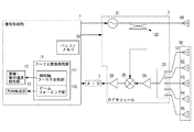
図1は本実施形態のFMCW方式レーダ装置の概略構成を示すブロック図である。
図1に示すように、本実施形態のレーダ装置は、送信信号制御、切り替え制御、物体検知を行う信号処理部1と、RFモジュール2と、送信アンテナ40と受信アンテナ50とを備える。
FIG. 1 is a block diagram showing a schematic configuration of the FMCW radar device of the present embodiment.
As shown in FIG. 1, the radar apparatus according to the present embodiment includes a
信号処理部1は、送信系制御として、送信制御信号の生成と切替制御信号の生成とを行う。送信制御信号は、時系列で三角形状に周波数を変調させた送信信号(以下、単に「三角波変調送信信号」と称する。)を生成するために、RFモジュール2のVCO21に与える信号である。また、切替制御信号は、受信アンテナ50のアンテナ素子51〜55を選択するためにRFモジュール2の出力切替回路23に与える信号である。
The
信号処理部1は、第1測定フェーズと第2測定フェーズとで異なる送信周期で、送信信号が生成されるように送信制御信号を出力する。この際、生成される三角波変調送信信号は、三角波変調された三角波変調区間と三角波変調区間の間の非変調区間とからなる。そして、三角波変調区間の時間長は、第1測定フェーズと第2測定フェーズとで同じであるが、非変調区間は、第1測定フェーズよりも第2測定フェーズが長くなるように設定されている。
The
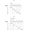
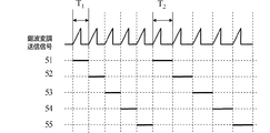
図2は送信制御と切替制御との同期状態を示す説明図であり、(A)は切替時間T1で切り替えた第1測定フェーズの場合、(B)は切替時間T2で切り替えた第2測定フェーズの場合を示す。なお、第2測定フェーズの切替時間T2は、第1測定フェーズの切替時間T1に所定時間Δtを加算した時間である。すなわち、T2=T1+Δtの関係となる。 Figure 2 is an explanatory diagram showing a synchronization state between the transmission control and the switching control, (A) in the case of the first measurement phase is switched by the switching time T 1, (B) the second of switching in the switching time T 2 The case of the measurement phase is shown. The second measurement phase switching time T 2 is a time obtained by adding a predetermined time Δt to the first measurement phase switching time T 1 . That is, the relationship is T 2 = T 1 + Δt.
このような送信制御処理と同時に、信号処理部1は、各三角波変調区間に各アンテナ素子51〜55が順次対応するように、各三角波変調区間の立ち上がりタイミングと、アンテナ素子51〜55の切り替わりタイミングとを一致させる切替制御信号を出力する。
Simultaneously with such transmission control processing, the
この際、アンテナ素子51〜55の切替パターンは、第1測定フェーズ、第2測定フェーズとで同じになる予め設定されたパターンからなる。例えば、図2に示すように、時系列順に、アンテナ素子51→アンテナ素子52→アンテナ素子53→アンテナ素子54→アンテナ素子55を繰り返す切替パターンを用いる。なお、送信信号の送信パターンおよびアンテナ素子の切替パターンは、これに限るものではなく、当明細書の実施の形態の終わりに記載するような各種パターンを繰り返すものであっても良い。
At this time, the switching pattern of the
RFモジュール2は、送信系回路としてVCO21、分配器22を備え、受信系回路として出力切替器23、RFアンプ24、ミキサ25、IFアンプ26を備える。
RFモジュール2の送信系として、VCO21は、所謂、電圧制御発振器からなり、信号処理部1からの送信制御信号を受けて三角波変調送信信号を生成し、分配器22に出力する。
The
As a transmission system of the
分配器22は方向性結合器からなり、VCO21からの三角波変調送信信号を送信アンテナ40に与えるとともに、三角波変調送信信号を電力分配してなるローカル信号を生成し、ミキサ25に与える。
The
送信アンテナ40は、単一のパッチアンテナ等からなり、三角波変調送信信号を電波に変換した送信波を、検知領域内に放射する。
The
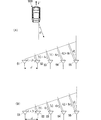
受信アンテナ50はアンテナ素子51〜55を備える。アンテナ素子51〜55は、パッチアンテナ等からなり、例えば誘電体基板上に直線上に等間隔で配列形成された複数のパッチ電極からなる。アンテナ素子51〜55の配列方向は、当該レーダ装置の正面方向(当該レーダ装置が設置される自動車の正面方向)に対して垂直な方向で、且つ水平方向に沿う方向である。そして、本実施形態ではより具体的な位置関係として、レーダ装置正面から見て右端から左端に向けてアンテナ素子51,52,53,54,55が順に並ぶものとする。
The receiving
受信アンテナ50の各アンテナ素子51〜55は、送信波に基づく物標の反射波等を受信して受信信号を生成し、RFモジュール2の出力切替器23に出力する。
The
RFモジュール2の受信系として、出力切替器23は、各アンテナ素子51〜55からの受信信号を受ける。出力切替器23には前述の切替制御信号が与えられており、出力切替器23は、この切替制御信号に基づいてアンテナ素子51〜55のいずれかとRFアンプ24との接続を切り替える。すなわち、切替制御信号により選択されたアンテナ素子の受信信号がRFアンプ24に与えられる。この際、アンテナ素子の切り替えは、第1測定フェーズでは送信周期T1に準じて行われ、第2測定フェーズでは送信周期T2に準じて行われ、前述の三角波変調区間毎に出力選択されたアンテナ素子の受信信号がRFアンプ24に与えられる。
As a reception system of the
RFアンプ24は、与えられた受信信号のゲイン制御を行い、ゲイン制御後のRF信号をミキサ25に出力する。
ミキサ25は、RF信号とローカル信号とを乗算してIFビート信号を生成し、IFアンプ26に与える。IFアンプ26は、IFビート信号のゲイン制御を行い、A/Dコンバータ3に出力する。
The
The
A/Dコンバータ3は、所定のサンプリング周期で増幅(ゲインコントロール)後のIFビート信号をサンプリングすることで、アナログのIFビート信号をディジタルのIFビート信号にコンバートして信号処理部1に出力する。
The A /
信号処理部1の受信系であるバッファメモリ10は、入力されるIFビート信号を順次バッファリングしていく。この際、バッファメモリ10には、測定フェーズ単位でIFビート信号がバッファリングされる。
The
フーリエ変換処理部11は、時間軸フーリエ変換部111、およびビームフォーミング部112を備える。時間軸フーリエ変換部111は、既知のFFT処理を用いて周波数スペクトルを生成して距離・相対速度検出部12に与える。ビームフォーミング部112は、時間軸フーリエ変換部で生成された周波数スペクトルを用いて、既知のビームフォーマ(Beamformer)法やCapon法を適用することで、方位方向スペクトルを生成して方位検出部13に与える。この際、フーリエ変換処理部11は、測定フェーズ単位で方位方向スペクトルを生成する。
The Fourier
距離・相対速度検出部12は、次に示す方法を用いて、自装置に対する検知物標の相対速度を算出する。
The distance / relative
[相対速度検知原理の説明]
本実施形態のレーダ装置は、次に示す原理に基づいて物標の相対速度を検知する。
図3〜図7は物標相対速度検知原理を説明するための図であり、図3は相対速度による物標までの距離の変化を示す。図3において、dはアンテナ素子の配置間隔を表し、r0はアンテナ素子51の受信信号を出力選択した時点での物標900とアンテナ素子51との距離を表し、rはアンテナ切替周期の応じた相対速度による距離変化量を表す。
[Description of the principle of relative speed detection]
The radar apparatus according to the present embodiment detects the relative speed of the target based on the following principle.
3 to 7 are diagrams for explaining the principle of detecting the target relative speed, and FIG. 3 shows a change in the distance to the target due to the relative speed. In FIG. 3, d represents the arrangement interval of the antenna elements, r 0 represents the distance between the
図3に示すように、物標900が自装置に対して「0」でない等速直線運動を行っている場合、一つの測定フェーズでは、アンテナ素子51の選択時の距離をr0とすると、アンテナ素子52の選択時の距離はr0+r、アンテナ素子53の選択時の距離はr0+2r、アンテナ素子54の選択時の距離はr0+3r、アンテナ素子55の選択時の距離はr0+4rとなる。したがって、受信アンテナ50の正面方向を0として相対速度による方位角をθVとし、アンテナ素子間隔をdとすると、θV=sin-1(2r/d)の方向に等位相面が生成されるのと同等となる。これが、測位フェーズにおける相対速度による方位角のズレに相当する。
As shown in FIG. 3, when the
このような状況において、第1測定フェーズ(送信周期T1)と第2測定フェーズ(送信周期T2)とで送信周期(切替周期)を異ならせると、各アンテナ素子選択時の距離は図4に示すような位相関係となる。 In such a situation, if the transmission period (switching period) is different between the first measurement phase (transmission period T 1 ) and the second measurement phase (transmission period T 2 ), the distance when each antenna element is selected is as shown in FIG. The phase relationship as shown in FIG.
図4(A)は、第1測定フェーズでの相対速度による物標までの距離の変化を示す図であり、図4(B)は、第2測定フェーズでの相対速度による物標までの距離の変化を示す図である。 FIG. 4A is a diagram illustrating a change in the distance to the target due to the relative speed in the first measurement phase, and FIG. 4B is a distance to the target due to the relative speed in the second measurement phase. It is a figure which shows the change of.
図4(A)に示すように、第1測定フェーズでは、送信周期T1に準じ、距離がr1毎に変化する。具体的には、アンテナ素子51の選択時の距離をr0とすると、アンテナ素子52の選択時の距離はr0+r1、アンテナ素子53の選択時の距離はr0+2r1、アンテナ素子54の選択時の距離はr0+3r1、アンテナ素子55の選択時の距離はr0+4r1となる。
As shown in FIG. 4A, in the first measurement phase, the distance changes every r 1 according to the transmission cycle T 1 . Specifically, when the distance at the time of selection of the
一方、図4(B)に示すように、第2測定フェーズでは、送信周期T2に準じ、距離がr2毎に変化する。具体的には、アンテナ素子51の選択時の距離をr0とすると、アンテナ素子52の選択時の距離はr0+r2、アンテナ素子53の選択時の距離はr0+2r2、アンテナ素子54の選択時の距離はr0+3r2、アンテナ素子55の選択時の距離はr0+4r2となる。ここで、r2=r1+Δrであり、Δrは、送信周期T1とT2との時間長の差Δtに準じた距離差である。
On the other hand, as shown in FIG. 4B, in the second measurement phase, the distance changes every r 2 according to the transmission cycle T 2 . Specifically, when the distance at the time of selection of the
このようにアンテナ素子間で物標の速度による距離変化が観測されると、レーダ装置に対する物標の方位による距離変化とともに、レーダ装置と物標との距離の変化は、図5に示す関係となる。
図5(A)は、第1測定フェーズでの物標までのレーダ装置からの往復距離の変化を示す図であり、図5(B)は、第2測定フェーズでの物標までのレーダ装置からの往復距離の変化を示す図である。
When a change in distance due to the speed of the target is observed between the antenna elements in this way, the change in the distance between the radar apparatus and the target as well as the distance change due to the direction of the target with respect to the radar apparatus is as shown in FIG. Become.
FIG. 5A is a diagram illustrating a change in the round-trip distance from the radar apparatus to the target in the first measurement phase, and FIG. 5B is a radar apparatus to the target in the second measurement phase. It is a figure which shows the change of the round-trip distance from.
第1測定フェーズでは、具体的に図5(A)に示すように、アンテナ素子51から仮想的な位相基準面までの距離を「0」とすると、各アンテナ素子52,53,54,55から仮想的な位相基準面までの距離は、それぞれL+2r1,2L+4r1,3L+6r1,4L+8r1となる。ここで、Lは物標の方位θによる距離変化分、2r1は物標の速度Vによる距離変化分である。
In the first measurement phase, as specifically shown in FIG. 5A, when the distance from the
また、第1測定フェーズに引き続く第2測定フェーズでは、具体的に図5(B)に示すように、アンテナ素子51から仮想的な位相基準面までの距離を「0」とすると、各アンテナ素子52,53,54,55から仮想的な位相基準面までの距離は、それぞれL+2r2,2L+4r2,3L+6r2,4L+8r2となる。ここで、Lは物標の方位θによる距離変化分、2r2は物標の速度Vによる距離変化分である。
Further, in the second measurement phase following the first measurement phase, as shown in FIG. 5B, when the distance from the
このような関係から、第1測定フェーズで算出される第1方位をθ1とし、第2測定フェーズで算出される第2方位をθ2とし、相対速度の影響を受けない真の方位をθとし、真の方位θに対する第1測定フェーズの方位のズレをθr1とし、真の方位θに対する第2測定フェーズの方位のズレをθr2とした場合に、次に二式が得られる。 From this relationship, the first direction calculated in the first measurement phase is θ 1 , the second direction calculated in the second measurement phase is θ 2, and the true direction that is not affected by the relative speed is θ If the deviation of the first measurement phase orientation relative to the true orientation θ is θ r1 and the orientation deviation of the second measurement phase orientation relative to the true orientation θ is θ r2 , then the following two equations are obtained.
L+2r1=−d(sinθ+sinθr1)=−d・sinθ1 −(5)
L+2r2=−d(sinθ+sinθr2)=−d・sinθ2 −(6)
なお、方位の符号は、図5に示すθ1,θ2の向きを負と定義している。
L + 2r 1 = −d (sin θ + sin θ r1 ) = − d · sin θ 1 − (5)
L + 2r 2 = −d (sin θ + sin θ r2 ) = − d · sin θ 2 − (6)
As for the sign of the azimuth, the directions of θ 1 and θ 2 shown in FIG. 5 are defined as negative.
ここで、Δr=r2−r1と定義すると、 Here, if defined as Δr = r 2 −r 1 ,
![]()
![]()
となる。この式(7)はすなわち、前述の相対速度候補Vを表す式(1)の右辺第一項そのものであるので、この演算処理を行うことで、物標の相対速度候補Vを算出することができる。 It becomes. In other words, since the equation (7) is the first term on the right side of the equation (1) representing the relative velocity candidate V, the relative velocity candidate V of the target can be calculated by performing this calculation process. it can.
信号処理部1は次の処理フローにより、上記相対速度候補Vを算出する。
The
まず、信号処理部1は、第1測定フェーズの受信信号群から方位方向スペクトルを算出し、方位角θ1の正弦値sinθ1を算出する。次に、信号処理部1は、第1測定フェーズに続く第2測定フェーズの受信信号群から方位方向スペクトルを算出し、方位角θ2の正弦値sinθ2を算出する。そして、信号処理部1は、算出したsinθ1、sinθ2を式(1)に適用して、相対速度候補Vを算出する。
First, the
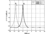
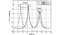
具体例として、受信アンテナ素子数を5とし、アンテナ間隔を1.46λ(λは76GHz送信信号の波長)、第1測定フェーズのアンテナ切替周期T1を1msec.とし、第2測定フェーズのアンテナ切替周期T2を1.05msec.とし、物標方位が5°、物標の相対速度が30km/hであった場合で、Capon法を用いてシミュレーションを行った場合の方位方向スペクトルを図6に示す。図6は、前述の第1測定フェーズでの受信信号による方位方向スペクトルと、第2測定フェーズでの受信信号による方位方向スペクトルとを示した図である。なお、図6以降の図で、図中のT1周期スキャンが第1測定フェーズの場合を示し、T2周期スキャンが第2測定フェーズの場合を示す。 As a specific example, the number of receiving antenna elements is 5, the antenna interval is 1.46λ (λ is the wavelength of a 76 GHz transmission signal), and the antenna switching period T 1 in the first measurement phase is 1 msec. And the antenna switching period T 2 in the second measurement phase is 1.05 msec. FIG. 6 shows the azimuth direction spectrum when the simulation is performed using the Capon method when the target orientation is 5 ° and the relative velocity of the target is 30 km / h. FIG. 6 is a diagram showing the azimuth direction spectrum by the received signal in the first measurement phase and the azimuth direction spectrum by the received signal in the second measurement phase. In FIG. 6 and subsequent figures, the case where the T 1 period scan in the drawing is the first measurement phase is shown, and the case where the T 2 period scan is the second measurement phase is shown.
図6に示すように、アンテナ素子51,52,53,54,55を切替周期T1で順に切り替える第1測定フェーズでの方位θ1は−5.00°となり、切替周期T2で順に切り替える第2測定フェーズでの方位θ2は−13.47°となる。したがって、算出される相対速度候補は、式(1)より、30.0±141.1×n km/hとなり、n=0の時の値がシミュレーションの仮定と一致する。今、仮に物標の取り得る速度が−40km/h〜100km/hであれば、真の相対速度は、30km/hであると特定できる。
As shown in FIG. 6, the orientation theta 1 of the first measuring phase for switching the order of the
このように、本実施形態の構成および処理を用いることにより、本実施形態のレーダ装置は、物標のドップラ周波数の算出等の煩雑な処理を行うことなく、物標の相対速度を確実に精度良く検知することができる。また、処理演算が簡素であるので、高精度な検知を高速に行うことができる。 As described above, by using the configuration and processing of the present embodiment, the radar apparatus of the present embodiment reliably ensures the relative speed of the target without performing complicated processing such as calculation of the Doppler frequency of the target. It can be detected well. Moreover, since the processing calculation is simple, highly accurate detection can be performed at high speed.
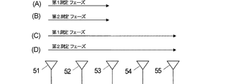
なお、前述の説明では、受信アンテナを構成する全てのアンテナ素子51〜55を用いて、第1測定フェーズおよび第2測定フェーズを構成したが、必ずしもアンテナ配列の一方端から他方端までの全てのアンテナ素子に切り替える必要はなく、図7に示すように、一部のアンテナ素子を切り替えるパターンであってもよい。図7は、アンテナ素子の切り替えモード別の切り替えパターンを表した図であり、(A),(B)が高速検知モードを示し、(C),(D)が通常検知モードを示す。
In the above description, the first measurement phase and the second measurement phase are configured using all the
信号処理部1には、モード切替機能が備えられており、例えば、ユーザからの操作入力等によりモードを切り替える。ここで、モードは、例えば、高速で相対速度を検出する高速検知モードと、通常の検知時間で相対速度を検出する通常検知モードとを備える。信号処理部1は、高速検知モードの選択を受け付けると、図7(A)に示す第1測定フェーズと、図7(B)に示す第2測定フェーズから相対速度を検知する。すなわち、まず、第1測定フェーズとして、アンテナ素子51〜53の三つのアンテナ素子を切替周期T1で切り替えて第1方位θ1を算出する。その後、第2測定フェーズとして、アンテナ素子51〜53の三つのアンテナ素子を切替周期T2で切り替えて第2方位θ2を算出する。そして、これら第1方位θ1と第2方位θ2とを用いて相対速度Vを算出する。この方法では、切替アンテナ素子数が少ないので、通常検知モードよりも高速で相対速度を検知することができる。
The
一方、信号処理部1は、通常検知モードの選択を受け付けると、図7(C)に示す第1測定フェーズと、図7(D)に示す第2測定フェーズから相対速度を検知する。すなわち、まず、第1測定フェーズとして、アンテナ素子51〜55の全てのアンテナ素子を切替周期T1で切り替えて第1方位θ1を算出する。その後、第2測定フェーズとして、アンテナ素子51〜55の全てのアンテナ素子を切替周期T2で切り替えて第2方位θ2を算出する。そして、これら第1方位θ1と第2方位θ2とを用いて相対速度Vを算出する。この方法では、高速検知モードよりも切替アンテナ素子数が多いので、高速検知モードよりも高精度に相対速度を検知することができる。
On the other hand, when receiving the selection of the normal detection mode, the
ところで、前述の説明では、アンテナ素子の切替間隔差Δtについて、時間範囲を指定しなかった。しかしながら、次に示す方法により切替間隔差Δtを設定することで、物標が取り得る相対速度の範囲内に現れる相対速度候補Vが唯一となり、あいまいさを排除して相対速度を算出することができる。
物標の相対速度が大きくなると、第1測定フェーズの切替周期T1と第2測定フェーズの切替周期T2との時間差(切替間隔差)Δtに対する距離差Δrも大きくなる。この往復の距離差2Δrに応じた位相差が第1測定フェーズと第2測定フェーズとの間で発生する。この際、送信信号の波長をλとして、この距離差2Δrに応じた位相差が、−λ/2〜+λ/2内に存在すれば、アンビギュイティは生じず、確実に相対速度Vを算出することができる。すなわち、2Δrによる位相差の絶対値が、λ/2以下であればよい。ここで、相対速度Vの候補は、λ/(2Δt)の間隔で現れる。したがって、相対速度Vの候補範囲における最大相対速度候補をVmax、最小相対速度候補をVminとすると、相対速度候補が一意に決定するのは、
By the way, in the above description, the time range is not specified for the antenna element switching interval difference Δt. However, by setting the switching interval difference Δt by the following method, the relative speed candidate V appearing within the range of the relative speed that can be taken by the target is unique, and the relative speed can be calculated without ambiguity. it can.
When the relative speed of the target increases, the distance difference Δr with respect to the time difference (switching interval difference) Δt between the switching period T 1 of the first measurement phase and the switching period T 2 of the second measurement phase also increases. A phase difference corresponding to the reciprocal distance difference 2Δr is generated between the first measurement phase and the second measurement phase. At this time, if the wavelength of the transmission signal is λ and the phase difference corresponding to the distance difference 2Δr exists within −λ / 2 to + λ / 2, ambiguity does not occur and the relative velocity V is calculated reliably. can do. That is, the absolute value of the phase difference due to 2Δr may be λ / 2 or less. Here, candidates for the relative velocity V appear at intervals of λ / (2Δt). Therefore, when the maximum relative speed candidate in the candidate range of the relative speed V is V max and the minimum relative speed candidate is V min , the relative speed candidate is uniquely determined as follows:
![]()
![]()
の条件を満たす場合である。このため、 This is the case where For this reason,
![]()
![]()
と、切替間隔差Δtを設定することで、一意に且つより確実に相対速度を算出することができる。また、一度物標を検出すると、相対速度の概算値を取得することができる。前回の測定にて得られた物標の相対速度をVprv、物標の運動の性質上あり得る最大の加速度をα、同じく減速度を−β、前回測定と今回測定路の時間差をτ、とすると、今回の測定時にて物標が取り得る速度の最大値Vmaxおよび最小値Vminは、それぞれ、Vprv+ατ、Vprv−βτと表せるので、
|Vmax−Vmin|=(Vprv+ατ)−(Vprv−βτ)=(α+β)τ −(9’)
と表すことができる。
And the relative speed can be calculated uniquely and more reliably by setting the switching interval difference Δt. Moreover, once the target is detected, an approximate value of the relative speed can be obtained. V prv is the relative velocity of the target obtained in the previous measurement, α is the maximum acceleration possible due to the nature of the target motion, -β is also the deceleration, and τ is the time difference between the previous measurement and the current measurement path. Then, the maximum value V max and the minimum value V min of the speed that the target can take at the time of this measurement can be expressed as V prv + ατ and V prv −βτ, respectively.
| V max −V min | = (V prv + ατ) − (V prv −βτ) = (α + β) τ− (9 ′)
It can be expressed as.
ここで、具体的なΔtの設定方法について説明する。まず、物標が未検知の状態では、例えば、物標が自動車であったとして、Vmax=+200km/h、Vmin=−200km/h、最大の加速度分α=5m/s2とし、最大の減速度分β=10m/s2とし、時間差τ=0.1sec.とし、式(9)および式(9’)より、切替間隔差Δt=1msec.とすればよい。 Here, a specific method for setting Δt will be described. First, in a state where the target is not detected, for example, assuming that the target is an automobile, V max = + 200 km / h, V min = −200 km / h, the maximum acceleration α = 5 m / s 2 , and the maximum The deceleration β is 10 m / s 2 and the time difference τ is 0.1 sec. From the equations (9) and (9 ′), the switching interval difference Δt = 1 msec. And it is sufficient.
このように切替間隔差Δtを設定することで、より確実に相対速度Vを算出することができる。 By setting the switching interval difference Δt in this way, the relative speed V can be calculated more reliably.
さらに、アンテナ素子間隔dを0.5λ以上とすると確実に物標の相対速度および方位の検知を行うことができる。 Furthermore, when the antenna element interval d is 0.5λ or more, the relative speed and direction of the target can be reliably detected.
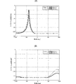
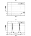
図8は、アンテナ間隔d=0.4λで、物標の真の方位が5°の時の方位方向スペクトルを示す図であり、(A)は物標の相対速度が2.0km/hである場合を示し、(B)は物標の相対速度が4.0km/hの場合を示す。
アンテナ素子間隔がdの場合、隣り合うアンテナ素子間で生じる距離差の検知範囲は、−d+nλ〜+d+nλ(nは整数)となる。すなわち、アンテナ素子と物標との位置関係による距離差と相対速度により生じる距離差とを加算した距離差は、−d+nλ〜+d+nλの範囲に入らなければ、前述の図6に示すような方位方向スペクトルのスペクトルピークが得られない。
FIG. 8 is a diagram showing the azimuth direction spectrum when the antenna interval is d = 0.4λ and the true azimuth of the target is 5 °. FIG. 8A shows the relative velocity of the target at 2.0 km / h. A case is shown, and (B) shows a case where the relative velocity of the target is 4.0 km / h.
When the antenna element interval is d, the detection range of the distance difference generated between adjacent antenna elements is −d + nλ to + d + nλ (n is an integer). That is, if the distance difference obtained by adding the distance difference due to the positional relationship between the antenna element and the target and the distance difference caused by the relative speed does not fall within the range of −d + nλ to + d + nλ, the azimuth direction as shown in FIG. The spectrum peak of the spectrum cannot be obtained.
ここで、例えばアンテナ素子間隔dが0.5λ未満(d=0.4λ)の場合、距離差検知範囲は−0.4λ+nλ〜0.4λ+nλとなる。第1測定フェーズの切替周期T1が1msec.で、第2測定フェーズの切替周期T2が1.05msec.で、物標の相対速度が2km/hである場合、隣り合うアンテナ素子間での距離差は0.32λとなる。この場合、前述の条件−0.4λ+nλ〜0.4λ+nλを満たすので、スペクトルピークが得られ(図8(A)参照)、相対速度の検知が可能となる。 Here, for example, when the antenna element interval d is less than 0.5λ (d = 0.4λ), the distance difference detection range is −0.4λ + nλ to 0.4λ + nλ. The switching period T 1 of the first measurement phase is 1 msec. The switching period T 2 of the second measurement phase is 1.05 msec. When the relative speed of the target is 2 km / h, the distance difference between adjacent antenna elements is 0.32λ. In this case, since the above-mentioned conditions −0.4λ + nλ to 0.4λ + nλ are satisfied, a spectrum peak is obtained (see FIG. 8A), and the relative velocity can be detected.
ところが、物標の相対速度が4km/hである場合、隣り合うアンテナ素子間での相対速度による距離変化は0.60λとなる。この場合、前述の条件−0.4λ+nλ〜0.4λ+nλを満たさないので、スペクトルピークが得られず(図8(B)参照)、正確に相対速度の検知を行うことができない。 However, when the relative speed of the target is 4 km / h, the distance change due to the relative speed between adjacent antenna elements is 0.60λ. In this case, since the above-mentioned conditions −0.4λ + nλ to 0.4λ + nλ are not satisfied, a spectrum peak cannot be obtained (see FIG. 8B), and the relative velocity cannot be accurately detected.
一方、アンテナ素子間隔dが0.5λ以上の場合、例えばd=0.8λとすると、隣り合うアンテナ素子間の距離差の検知範囲は、(−0.8+n)λ〜(0.8+n)λとなる。この場合、n=mの時の範囲と、n=m+1の時の範囲とはオーバラップするので、全ての距離差が検知可能となる。つまり、アンテナ素子と物標との位置関係による距離差と相対速度により生じる距離差とを加算した距離差は、−d+nλ〜+d+nλの範囲に確実に存在する。この結果、アンテナ素子間隔dを0.5λ以上とすることで、方位方向のスペクトルピークを確実に得られ、物標の相対速度を検知することができる。 On the other hand, when the antenna element interval d is 0.5λ or more, for example, if d = 0.8λ, the detection range of the distance difference between adjacent antenna elements is (−0.8 + n) λ to (0.8 + n) λ. It becomes. In this case, since the range when n = m and the range when n = m + 1 overlap, all the distance differences can be detected. That is, the distance difference obtained by adding the distance difference due to the positional relationship between the antenna element and the target and the distance difference caused by the relative speed surely exists in the range of −d + nλ to + d + nλ. As a result, by setting the antenna element interval d to 0.5λ or more, a spectrum peak in the azimuth direction can be reliably obtained, and the relative velocity of the target can be detected.
また、前述の説明では、アンテナ素子間隔dを0.5λ以上にすることで、確実且つ容易にスペクトルピークを得られることを示したが、アンテナ素子間隔dが0.5λ未満であっても、Capon法やBeamformer法の算術上、仮想的にアンテナ素子間隔dを0.5λ以上に設定することで、スペクトルピークを得ることもできる。 In the above description, it has been shown that the spectral peak can be obtained reliably and easily by setting the antenna element interval d to 0.5λ or more. However, even if the antenna element interval d is less than 0.5λ, A spectrum peak can also be obtained by virtually setting the antenna element interval d to 0.5λ or more in the arithmetic of the Capon method and the beamformer method.
Capon法やBeamformer法等では、到来方向推定演算に、次式に示すモードベクトルを用いる。 In the Capon method, Beamformer method, etc., the mode vector shown in the following equation is used for the arrival direction estimation calculation.

ここで、a(θ)は、推定方位θに対するモードベクトル、d1〜dkはアンテナ素子数k+1個において、一つのアンテナ素子位置を基準位置とした場合の各アンテナ間隔を示す。
アンテナ素子間隔dが0.5λ未満である場合に、(式A)のd1〜dkに現実のアンテナ素子間隔dを用いるのではなく、仮想設定したアンテナ素子間隔d’を用いる。
Here, a (θ) represents a mode vector with respect to the estimated azimuth θ, and d1 to dk represent antenna intervals when one antenna element position is a reference position in the number of antenna elements k + 1.
When the antenna element interval d is less than 0.5λ, the actual antenna element interval d ′ is used instead of the actual antenna element interval d for d1 to dk in (Formula A).
この演算処理により、図9(B)に示すような方位方向スペクトルが得られる。
図9は方位方向スペクトルを示す図であり、(A)は現実のアンテナ素子間隔d=0.4λを用いた場合を示し、(B)仮想設定したアンテナ素子間隔d’=2d=0.8λを用いた場合を示す。
なお、図9に示す方位方向スペクトルは、図8(B)に示した方位方向スペクトルと同じ条件により得られたものである。すなわち、図9(A)と図8(B)とは同じ結果を示す。
By this calculation process, an azimuth direction spectrum as shown in FIG. 9B is obtained.
9A and 9B are diagrams showing the azimuth direction spectrum, where FIG. 9A shows a case where an actual antenna element interval d = 0.4λ is used, and FIG. 9B shows a virtually set antenna element interval d ′ = 2d = 0.8λ. The case where is used is shown.
Note that the azimuth direction spectrum shown in FIG. 9 is obtained under the same conditions as the azimuth direction spectrum shown in FIG. That is, FIG. 9A and FIG. 8B show the same result.
図9(B)に示すように、アンテナ素子間隔d’を0.5λ以上に仮想設定した場合、急峻なスペクトルピークが得られる。 As shown in FIG. 9B, when the antenna element interval d ′ is virtually set to 0.5λ or more, a steep spectral peak is obtained.
このようにアンテナ素子間隔を仮想的に0.5λ以上に設定することで、現実のアンテナ素子間隔dが0.5λ未満であっても相対速度に影響されることなく、スペクトルピークを得ることができる。 By virtually setting the antenna element interval to 0.5λ or more in this way, a spectrum peak can be obtained without being affected by the relative speed even if the actual antenna element interval d is less than 0.5λ. it can.
このように得られたスペクトルピークによる第1測定フェーズでの方位θ1’と、第2測定フェーズでの方位θ2’とは、現実の方位θとは異なる。しかしながら、現実の方位θと算出方位θ’とは、等位相面までの距離をLとして、
L=d・sinθ=d’・sinθ’
の関係が成り立つので、
現実の方位θは、
θ=sin-1((d’/d)・sinθ’) −(式B)
から得ることができる。
The azimuth θ 1 ′ in the first measurement phase and the azimuth θ 2 ′ in the second measurement phase based on the spectrum peak thus obtained are different from the actual azimuth θ. However, the actual azimuth θ and the calculated azimuth θ ′ are L as the distance to the equiphase plane,
L = d · sin θ = d ′ · sin θ ′
Since the relationship of
The actual orientation θ is
θ = sin −1 ((d ′ / d) · sin θ ′) − (formula B)
Can be obtained from
このように、現実には、アンテナ素子間隔dが0.5λ未満であっても、算術演算上、仮想的にアンテナ素子間隔d’を0.5λ以上とすることで、処理演算数は増加するが、方位θを得ることができる。この結果、算出された各測定フェーズの方位θ1、θ2を用いて相対速度Vを算出することができる。 As described above, in reality, even if the antenna element interval d is less than 0.5λ, the number of processing operations increases by virtually setting the antenna element interval d ′ to 0.5λ or more in arithmetic operations. However, the azimuth θ can be obtained. As a result, the relative velocity V can be calculated using the calculated directions θ1 and θ2 of each measurement phase.
次に、第2の実施形態に係るレーダ装置およびレーダ装置の物標検知方法について図を参照して説明する。
本実施形態のレーダ装置は、アンテナ間隔dのみが異なり、他の構成は、第1の実施形態のレーダ装置と同じである。
本実施形態では、物標の相対速度Vとともに、物標の真の方位θをも算出するものであり、以下は真の方位θの算出方法について具体的に説明する。
Next, a radar apparatus and a target detection method for the radar apparatus according to the second embodiment will be described with reference to the drawings.
The radar apparatus of this embodiment is different only in the antenna interval d, and the other configuration is the same as that of the radar apparatus of the first embodiment.
In the present embodiment, the true azimuth θ of the target is calculated together with the relative velocity V of the target, and a method for calculating the true azimuth θ will be specifically described below.
ターゲットの相対速度が大きくなると、隣り合うアンテナ素子間の相対速度により生じる距離差rも大きくなる。通常、相対速度により生じる距離差rが−λ/2〜+λ/2の範囲に入るように設計すれば、アンビギュイティは発生しない。しかしながら、相対速度による距離差rが−λ/2〜+λ/2の範囲に入らない場合、rとr+nλ(nは整数)との判別ができなくなる。 As the relative speed of the target increases, the distance difference r caused by the relative speed between adjacent antenna elements also increases. Usually, if the distance difference r caused by the relative speed is designed to fall within the range of -λ / 2 to + λ / 2, ambiguity will not occur. However, when the distance difference r due to the relative speed does not fall within the range of -λ / 2 to + λ / 2, it is impossible to distinguish between r and r + nλ (n is an integer).
この場合、第1測定フェーズの第1方位をθ1とすると、
L+2r1+nλ=−d・sinθ1 −(10)
となる。ただし、nは任意の整数である。
In this case, if the first direction of the first measurement phase is θ 1 ,
L + 2r 1 + nλ = −d · sin θ 1 − (10)
It becomes. However, n is an arbitrary integer.
このような組み合わせを持つ方位の候補が複数になる。ここで、物標の相対速度をV、真の方位θは、
r1=V・T1 −(11−1)
L=−d・sinθ −(11−2)
であるので、式(10)、(11−1)、(11−2)より、
There are a plurality of azimuth candidates having such a combination. Here, the relative velocity of the target is V, and the true direction θ is
r 1 = V · T 1- (11-1)
L = −d · sin θ− (11-2)
Therefore, from the equations (10), (11-1), (11-2)
![]()
![]()
となる。したがって、式(12)より、真の方位θの正弦値sinθは、λ/dの間隔で候補が発生する。 It becomes. Therefore, from equation (12), candidates for the sine value sin θ in the true direction θ are generated at intervals of λ / d.
このように、正弦値sinθはλ/dの間隔で発生するので、sinθを特定するには、θの取りうる値を、レーダの正面方向すなわち複数のアンテナ素子の配列方向に垂直で且つ送信信号の送信方向を0°方向とした場合に、−90°〜+90°の範囲内において最小値でθmin、最大値でθmaxとして、 As described above, since the sine value sin θ is generated at intervals of λ / d, in order to specify sin θ, the possible value of θ is set to be perpendicular to the front direction of the radar, that is, the arrangement direction of the plurality of antenna elements, and the transmission signal. When the transmission direction is set to 0 ° direction, θ min is the minimum value and θ max is the maximum value within the range of −90 ° to + 90 °,
![]()
![]()
に限定すればよい。これにより、候補は一意に決定し、真の方位が特定できる。 It may be limited to. Thereby, a candidate is determined uniquely and a true direction can be specified.
したがって、 Therefore,
![]()
![]()
となるように、アンテナ素子間隔dを設定することで、確実且つ容易に真の方位θを算出することができる。この際、相対速度Vは、真の方位θの算出時に利用するsinθ1とsinθ2とを用いて、前述の実施形態の演算を行うことで得られる。 By setting the antenna element interval d so as to be true, the true azimuth θ can be calculated reliably and easily. At this time, the relative velocity V can be obtained by performing the calculation of the above-described embodiment using sin θ 1 and sin θ 2 used when calculating the true direction θ.
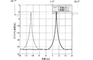
図10は本実施形態の構成および処理で得られる方位方向スペクトルの一例を示す図である。図10に示す方位方向スペクトルは、送信信号の周波数を76GHz、波長λを3.9mmとし、第1測定フェーズの切替周期T1を1msec.とし、第2測定フェーズの切替周期T2を1.05msec.とし、物標方位θを5°とし、物標の相対速度を70km/hとした時のシミュレーション結果である。 FIG. 10 is a diagram showing an example of the azimuth direction spectrum obtained by the configuration and processing of the present embodiment. The azimuth direction spectrum shown in FIG. 10 has a transmission signal frequency of 76 GHz, a wavelength λ of 3.9 mm, and a first measurement phase switching period T 1 of 1 msec. And the switching period T 2 of the second measurement phase is 1.05 msec. And the simulation result when the target direction θ is 5 ° and the relative speed of the target is 70 km / h.
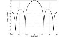
アンテナ素子間隔dは、θmaxを+20°、θminを−20°に設定することで、式(14)から1.46λに決定されるが、ここでは境界値としてd=1.46λを設定している。θmax=20°,θmin=−20°を実現するため、本実施形態のレーダ装置では、例えば、図11に示すような指向特性を有する送受信ビームパターンを形成する。図11は本実施形態の送受信ビームパターンを示した図である。このような送受信ビームパターンは、送信アンテナおよび受信アンテナの構成および送受信制御により設定可能である。 The antenna element interval d is determined to be 1.46λ from equation (14) by setting θ max to + 20 ° and θ min to −20 °, but here, d = 1.46λ is set as the boundary value. is doing. In order to realize θ max = 20 ° and θ min = −20 °, the radar apparatus of this embodiment forms, for example, a transmission / reception beam pattern having directivity characteristics as shown in FIG. FIG. 11 is a diagram showing a transmission / reception beam pattern of the present embodiment. Such a transmission / reception beam pattern can be set by the configuration of transmission antennas and reception antennas and transmission / reception control.
図10に示すように、本実施形態のアンテナ素子の配置間隔dを用いることで、第1測定フェーズの第1方位θ1を式(12)に代入して得られるθのうち、θmax〜θminの範囲にあるものは1つだけ存在する。第2測定フェーズの第2方位θ2を式(12)のθ1の代わりに用いて得られるθも同様にθmax〜θminの範囲にあるものは1つだけである。sinθ1とsinθ2とから、前述の実施形態の式(1)を用いることで相対速度候補Vを算出することができる。具体的に、図10の例では、θ1=7.96°、θ2=−11.62°であるので、相対速度候補Vは70.0±141.1×n km/hとなり、n=0の時の値が仮定と一致する。今、仮に物標の取り得る速度が−40km/h〜+100km/hであれば、真の相対速度は70km/hであると特定できる。 As shown in FIG. 10, among the θs obtained by substituting the first orientation θ 1 of the first measurement phase into the equation (12) by using the antenna element arrangement interval d of the present embodiment, θ max to There is only one in the θ min range. Similarly, there is only one θ obtained by using the second orientation θ 2 of the second measurement phase instead of θ 1 in the equation (12) in the range of θ max to θ min . The relative speed candidate V can be calculated from sin θ 1 and sin θ 2 by using equation (1) of the above-described embodiment. Specifically, in the example of FIG. 10, θ 1 = 7.96 ° and θ 2 = −11.62 °, so the relative speed candidate V is 70.0 ± 141.1 × n km / h, and n The value when = 0 matches the assumption. Now, if the speed that the target can take is -40 km / h to +100 km / h, the true relative speed can be specified to be 70 km / h.
次に、真の方位θの正弦値sinθは、式(12)に示すように、λ/d毎に現れるので、θ1=7.96°から、真の方位θの候補は、現実的に送信信号により検知し得るであろう範囲である−90°〜+90°の範囲内で、−36.7°,+5.0°,+50.5°となる。しかしながら、送信ビーム範囲を−20°〜+20°に設定しているので、真の方位θは一意に5.0°に決定される。そして、この結果は仮定と一致する。 Next, since the sine value sin θ of the true azimuth θ appears every λ / d as shown in the equation (12), from θ 1 = 7.96 °, the true azimuth θ candidate is realistically Within the range of −90 ° to + 90 ° that can be detected by the transmission signal, −36.7 °, + 5.0 °, and + 50.5 °. However, since the transmission beam range is set to −20 ° to + 20 °, the true azimuth θ is uniquely determined to be 5.0 °. This result is consistent with the assumption.
以上のように、本実施形態の構成および処理を行うことで、物標の相対速度と方位とを確実に且つ正確に検知することができる。 As described above, by performing the configuration and processing of the present embodiment, it is possible to reliably and accurately detect the relative speed and direction of the target.
なお、本実施形態では、検知範囲をθmin〜θmaxに設定したが、前述の0°方向を中心にして角度の正方向、負方向ともに同じ角度範囲内に設定する場合は、式(14)に代わり、 In the present embodiment, the detection range is set to θ min to θ max . However, when both the positive direction and the negative direction of the angle are set within the same angle range with the 0 ° direction as the center, the equation (14) Instead of
![]()
![]()
を用いてもよい。 May be used.
次に、第3の実施形態に係るレーダ装置およびレーダ装置の物標検知方法について図を参照して説明する。
本実施形態のレーダ装置は、アンテナ素子間隔が不等間隔であり、他の構成は第1、第2の実施形態のレーダ装置と同じである。
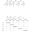
図12(A)はアンテナ素子間隔を示す図であり、(B)は送信制御と切替制御との同期状態を示す説明図である。
Next, a radar apparatus and a target detection method for the radar apparatus according to the third embodiment will be described with reference to the drawings.
The radar apparatus according to the present embodiment has unequal antenna element intervals, and the other configurations are the same as those of the first and second embodiments.
FIG. 12A is a diagram illustrating antenna element intervals, and FIG. 12B is an explanatory diagram illustrating a synchronization state between transmission control and switching control.
図12(A)に示すように、本実施形態のレーダ装置では、アンテナ素子51〜55の間隔を、アンテナ素子51側から順に、2d,2d,3d,3dとする。そして、図12(B)に示すように、信号処理部1は、アンテナ素子51,52,53,54,55の順でアンテナ素子を切り替える場合、第1測定フェーズでは、τ=T1すなわち2T1,2T1,3T1,3T1の時間間隔で切り替え、第2測定フェーズでは、τ=T2すなわち2T2,2T2,3T2,3T2の時間間隔で切り替える。
As shown in FIG. 12A, in the radar apparatus of the present embodiment, the intervals between the
不等間隔アレーアンテナの場合、アンテナ素子間隔の最大公約数によりグレーティングローブの発生間隔が決定する。このため、アンテナ素子間隔の最大公約数をdとすると、前述の第1実施形態および第2実施形態の条件から、 In the case of an unequally spaced array antenna, the grating lobe generation interval is determined by the greatest common divisor of the antenna element intervals. For this reason, assuming that the greatest common divisor of the antenna element spacing is d, from the conditions of the first and second embodiments described above,
![]()
![]()
を満たすように、dを決定すれば、相対速度Vおよび真の方位θを一意に決定することができる。あるいは、d<0.5λの時も、前述の仮想的な間隔d’(d’>0.5λ)を用い、全く同様に式(B)からθを算出し、続いて相対速度Vを一意に決定できる。 If d is determined so as to satisfy, the relative velocity V and the true orientation θ can be uniquely determined. Alternatively, when d <0.5λ, θ is calculated from Equation (B) in the same manner using the above-described virtual interval d ′ (d ′> 0.5λ), and then the relative velocity V is uniquely set. Can be determined.
このような構成および処理を用いることで、不等間隔アレイによって方位分解能を向上させ、且つ確実に相対速度Vと真の方位θとを検知することができる。すなわち、高精度で確実に相対速度Vと真の方位θとを検知することができる。 By using such a configuration and processing, it is possible to improve the azimuth resolution by the unequal interval array and reliably detect the relative velocity V and the true azimuth θ. That is, the relative speed V and the true orientation θ can be detected with high accuracy and reliability.
次に、第4の実施形態に係るレーダ装置およびレーダ装置の物標検知方法について説明する。
本実施形態では、推定演算する方位角範囲(推定演算方位角範囲)を設定するものであり、他の構成は第3の実施形態に示したレーダ装置と同じである。
Next, a radar apparatus and a target detection method for the radar apparatus according to the fourth embodiment will be described.
In the present embodiment, an azimuth angle range (estimated calculation azimuth angle range) for estimation calculation is set, and other configurations are the same as those of the radar apparatus shown in the third embodiment.
推定演算方位角範囲を−θcal〜+θcalに設定した場合、最大演算方位角θcalを、
θcal=sin-1(λ/(2d)) −(17)
とする。
When the estimated calculation azimuth angle range is set to -θ cal to + θ cal , the maximum calculation azimuth angle θ cal is
θ cal = sin −1 (λ / (2d)) − (17)
And
この関係式は、前述の原理から導かれるものであり、式(17)に示す設定を行うことで、第1測定フェーズの第1方位θ1、第2測定フェーズの第2方位θ2ともに、スペクトルピークは一個になる。これにより、確実且つ容易に相対速度Vと真の方位θとを算出することができる。さらに、本実施形態では、推定演算方位角範囲を、前述の実施形態よりも実質的に狭くすることができるので、相対速度および方位算出の演算負荷を軽減することができる。 This relational expression is derived from the above-described principle. By performing the setting shown in Expression (17), the first orientation θ 1 in the first measurement phase and the second orientation θ 2 in the second measurement phase are both There is one spectral peak. As a result, the relative speed V and the true orientation θ can be calculated reliably and easily. Furthermore, in the present embodiment, the estimated calculation azimuth angle range can be made substantially narrower than in the above-described embodiment, so that the calculation load for relative speed and azimuth calculation can be reduced.
次に、第5の実施形態に係るレーダ装置およびレーダ装置の物標検知方法について図を参照して説明する。 Next, a radar apparatus and a target detection method for the radar apparatus according to a fifth embodiment will be described with reference to the drawings.
本実施形態は、前述の各実施形態のような物標が一つの場合の処理に関するものではなく、検知領域内で、自装置から略等距離に、複数の物標が存在する場合の処理に関するものである。
図13は複数の物標が同距離で異なる方位に存在して異なる相対速度を有する場合の方位方向スペクトルを示す図である。
第1測定フェーズでの受信信号によるスペクトルピークのレベルと、第2測定フェーズでの受信信号によるスペクトルピークのレベルとは、対象となる物標が同じ(単一)であれば、略同じとなる。したがって、物標毎にスペクトルピークレベルが相違し、同じ物標に対する第1測定フェーズのスペクトルピークレベルと第2測定フェーズのスペクトルピークレベルとは略同じになる。
This embodiment does not relate to processing when there is a single target as in each of the above-described embodiments, but relates to processing when a plurality of targets exist at a substantially equal distance from the own device within the detection area. Is.
FIG. 13 is a diagram illustrating an azimuth direction spectrum in the case where a plurality of targets exist in different directions at the same distance and have different relative velocities.
The level of the spectrum peak due to the received signal in the first measurement phase and the level of the spectrum peak due to the received signal in the second measurement phase are substantially the same if the target target is the same (single). . Therefore, the spectrum peak level is different for each target, and the spectrum peak level in the first measurement phase and the spectrum peak level in the second measurement phase for the same target are substantially the same.
これを利用し、信号処理部1は、得られたスペクトルピークから、ピークレベルに基づいて、第1測定フェーズのスペクトルピークと第2測定フェーズのスペクトルピークとをペアリングする。そして、信号処理部1は、ペアリングした第1測定フェーズのスペクトルピークと第2測定フェーズのスペクトルピークとを用いて、前述の各種方法を用いて各物標の相対速度と真の方位とを検知する。このような処理方法を用いることにより、自装置から同距離で異なる相対速度および方位の物標が複数存在しても、それぞれの相対速度および方位を確実且つ高精度に検知することができる。
Using this, the
なお、このペアリングの際に、スペクトルピークのピークレベルのみでなく、スペクトルピークの形状をも参照してペアリングを行っても良い。 In this pairing, pairing may be performed by referring not only to the peak level of the spectrum peak but also to the shape of the spectrum peak.
さらに、第1測定フェーズと第2測定フェーズとの位相差が2VΔt/λであることを利用し、以下の方法で、間隔時間差Δtを短くしていき、ペアとなるスペクトルピークを決定しても良い。 Furthermore, using the fact that the phase difference between the first measurement phase and the second measurement phase is 2VΔt / λ, the interval time difference Δt is shortened by the following method to determine a pair of spectral peaks. good.
物標の取り得る相対速度の上限および下限をそれぞれ、Vmax,Vminとする。ここで、第1の実施形態に示した条件下で間隔時間差Δtを設定することで、位相差が2πを超えることはないので、式(1)から、第1方位θ1に対して、第2方位の制限値sinθ2を、 The upper and lower limits of the relative speed that can be taken by the target are set to V max and V min , respectively. Here, since the phase difference does not exceed 2π by setting the interval time difference Δt under the conditions shown in the first embodiment, the first difference θ 1 The limit value sinθ 2 in two directions is
![]()
![]()
の範囲内に納めるように、θ2を検出すればよい。この際、式(18)の範囲内に複数のθ2候補が存在する場合には、徐々に間隔時間差Δtを短く設定していき、θ2候補を一つまで絞り込むことで、確実にペアリングを行うことができる。 It is sufficient to detect θ 2 so that it falls within the range of. At this time, if there are a plurality of θ 2 candidates within the range of the equation (18), the interval time difference Δt is gradually set to be short, and the θ 2 candidates are narrowed down to one to ensure pairing. It can be performed.
これにより、確実に相対速度Vを算出することができる。そして、一度相対速度Vを算出すれば、これ以降は、間隔時間差Δtを長くして相対速度の分解能を上げるようにすればよい。この結果、確実に物標の相対速度を算出することができるとともに、徐々に高精度に相対速度を算出することができる。 Thereby, the relative speed V can be calculated reliably. Once the relative speed V is calculated, the interval time difference Δt is increased thereafter to increase the resolution of the relative speed. As a result, the relative speed of the target can be reliably calculated, and the relative speed can be gradually and accurately calculated.
なお、前述の実施形態では、送信信号波形およびアンテナ素子の切替の一例として、三角波変調信号で第1測定フェーズとしてアンテナ素子を51→52→53→54→55の順に切替周期T1で切り替え、第2測定フェーズとしてアンテナ素子を51→52→53→54→55の順に切替周期T2で切り替える例を示した。 In the above-described embodiment, as an example of switching of the transmission signal waveform and the antenna element, the antenna element is switched at the switching cycle T1 in the order of 51 → 52 → 53 → 54 → 55 as the first measurement phase with the triangular wave modulation signal, An example in which the antenna elements are switched at the switching cycle T2 in the order of 51 → 52 → 53 → 54 → 55 as two measurement phases is shown.
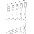
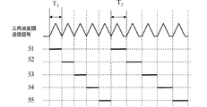
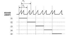
しかしながら、図14〜図17に示すような送信信号波形およびアンテナ素子の切替を用いても、前述の構成、処理を実現でき、前述の効果を奏することができる。 However, even when the transmission signal waveform and the switching of the antenna elements as shown in FIGS. 14 to 17 are used, the above-described configuration and processing can be realized, and the above-described effects can be achieved.
図14〜図17は、その他の送信信号波形および送信制御と切替制御との同期状態を示す説明図である。 14 to 17 are explanatory diagrams showing other transmission signal waveforms and synchronization states between transmission control and switching control.
図14は、上り変調区間のみを有する、所謂鋸波変調信号を用いており、変調区間の波形は同じで非変調区間の長さが第1測定フェーズと第2測定フェーズとで異なるものである。
図15は、三角波変調信号を用いており、第1測定フェーズでは非変調区間が無く、第2測定フェーズでは非変調区間を設けたものである。
図16は、鋸波変調信号を用いており、一つの送信周期内に二つの変調区間を有するものである。そして、一つの送信周期内の二つの変調区間の間隔が各送信周期で異なる。この際、各アンテナ素子51〜55は、送信周期により切替制御される。そして、各アンテナ素子51〜55が受信する送信周期の最初の(第1の)変調区間に対応する鋸波変調信号にて第1測定フェーズを構成し、各アンテナ素子51〜55が受信する送信周期の第2の変調区間に対応する鋸波変調信号にて第2測定フェーズを構成する。
FIG. 14 uses a so-called sawtooth modulation signal having only an upstream modulation section, and the waveform of the modulation section is the same and the length of the non-modulation section is different between the first measurement phase and the second measurement phase. .
FIG. 15 uses a triangular wave modulation signal, in which there is no non-modulation section in the first measurement phase, and a non-modulation section is provided in the second measurement phase.
FIG. 16 uses a sawtooth modulation signal, and has two modulation sections within one transmission period. The interval between the two modulation sections in one transmission cycle is different in each transmission cycle. At this time, the
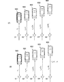
図17は、上り変調区間と下り変調区間とが存在する三角波変調信号を用いるが、上り変調区間と下り変調区間との間に無変調区間を有する三角波変調信号を用いる。この無変調区間は各三角波変調信号により異なる。 FIG. 17 uses a triangular wave modulation signal having an uplink modulation interval and a downlink modulation interval, but uses a triangular wave modulation signal having a non-modulation interval between the uplink modulation interval and the downlink modulation interval. This non-modulation section varies depending on each triangular wave modulation signal.
そして、各アンテナ素子51〜55が受信する三角波変調信号の上り変調区間の信号にて第1測定フェーズを構成し、各アンテナ素子51〜55が受信する三角波変調信号の下り変調区間の信号にて第2測定フェーズを構成する。
Then, the first measurement phase is constituted by the signals in the upstream modulation section of the triangular wave modulation signal received by each
また、前述の実施形態では、受信アンテナを複数のアンテナ素子を配列してなるアレイアンテナとした例を示したが、送信アンテナをアレイアンテナとしたり、送信アンテナおよび受信アンテナの双方をアレイアンテナにしても、前述の効果を同様に奏することができる。 In the above-described embodiment, an example in which the reception antenna is an array antenna formed by arranging a plurality of antenna elements has been described. However, the transmission antenna is an array antenna, or both the transmission antenna and the reception antenna are array antennas. The same effect as described above can be obtained.
1−信号処理部、10−バッファメモリ、11−フーリエ変換処理部、111−時間軸フーリエ変換部、112−ビームフォーミング部、12−距離・相対速度検出部、13−方位検出部、2−RFモジュール、21−VCO、22−分配器、23−出力切替器、24−RFアンプ、25−ミキサ、26−IFアンプ、3−A/Dコンバータ、40−送信アンテナ、50−受信アンテナ、51〜55−アンテナ素子 1-signal processing unit, 10-buffer memory, 11-Fourier transform processing unit, 111-time axis Fourier transform unit, 112-beam forming unit, 12-distance / relative velocity detection unit, 13-azimuth detection unit, 2-RF Module, 21-VCO, 22-distributor, 23-output switch, 24-RF amplifier, 25-mixer, 26-IF amplifier, 3-A / D converter, 40-transmit antenna, 50-receive antenna, 51- 55-antenna element
Claims (16)
前記複数のアンテナ素子を予め設定した所定切替パターンに基づいて、第1の時間間隔で切り替えて、物標の第1方位を算出する第1測定フェーズと、
前記複数のアンテナ素子を前記所定切替パターンに基づいて、前記第1の時間間隔とは異なる第2の時間間隔で切り替えて、前記物標の第2方位を算出する第2測定フェーズと、を有し、
前記第1方位、前記第2方位、前記第1の時間間隔、前記第2の時間間隔、および前記複数のアンテナ素子の配置間隔に基づいて前記物標の相対速度を算出するレーダの物標検知方法。Radar target detection in which at least one of the transmission antenna and the reception antenna is constituted by a plurality of antenna elements arranged on a straight line, and the plurality of antenna elements arranged on the straight line are switched in synchronization with the modulation period of the transmission signal. A method,
A first measurement phase in which the plurality of antenna elements are switched at a first time interval based on a predetermined switching pattern set in advance to calculate a first orientation of the target;
A second measurement phase for calculating the second orientation of the target by switching the plurality of antenna elements at a second time interval different from the first time interval based on the predetermined switching pattern. And
Radar target detection for calculating a relative velocity of the target based on the first azimuth, the second azimuth, the first time interval, the second time interval, and an arrangement interval of the plurality of antenna elements. Method.
演算式
V=d・(sinθ1−sinθ2)/(2・Δt)+n・λ/(2・Δt)
を用いて得られる候補の中から1つを選択して前記物標の相対速度を算出する請求項1に記載のレーダの物標検知方法。A direction perpendicular to the arrangement direction of the plurality of antenna elements on the radiation direction side of the transmission signal is a 0 ° direction, and is an angle extending from the 0 ° direction to the arrangement direction, and is within a range of −90 ° to + 90 °. , Θ 1 and θ 2 , respectively, the time difference between the first time interval and the second time interval is Δt, and the intervals between the plurality of antenna elements are d, the target object in the relative speed candidate and V, and n is an arbitrary integer, the wavelength of the transmission signal as a lambda,
Formula V = d · (sin θ 1 −sin θ 2 ) / (2 · Δt) + n · λ / (2 · Δt)
The radar target detection method according to claim 1, wherein a relative speed of the target is calculated by selecting one of candidates obtained by using.
Δt<λ/(2|Vmax−Vmin|)
となるように、前記第1の時間間隔と前記第2の時間間隔との差Δtを設定する請求項1または請求項2に記載のレーダの物標検知方法。The relative speed that the target can take is V min to V max , the time difference between the first time interval and the second time interval is Δt, and the wavelength of the transmission / reception signal is λ,
Δt <λ / (2 | V max −V min |)
The radar target detection method according to claim 1, wherein a difference Δt between the first time interval and the second time interval is set such that
d<λ/|sinθmax−sinθmin|
となるように、前記複数のアンテナ素子の配置間隔を設定する請求項1〜3のいずれかに記載のレーダの物標検知方法。A direction perpendicular to the arrangement direction of the plurality of antenna elements on the radiation direction side of the transmission signal is a 0 ° direction, and is an angular range extending from the 0 ° direction to the arrangement direction, and a range of −90 ° to + 90 °. The detection azimuth angle range θ min to θ max is set inside, the arrangement interval of the plurality of antenna elements is d, and the wavelength of the transmission / reception signal is λ,
d <λ / | sin θ max −sin θ min |
The radar target detection method according to claim 1, wherein arrangement intervals of the plurality of antenna elements are set so that
θcal=sin-1(λ/(2d))
の関係が成立するように、前記複数のアンテナ素子の配置間隔をdに設定し、送受信信号の波長をλに設定して、前記物標の相対速度と方位とを算出する請求項1〜4のいずれかに記載のレーダの物標検知方法。A direction perpendicular to the arrangement direction of the plurality of antenna elements on the radiation direction side of the transmission signal is defined as 0 ° direction, and the calculated azimuth angle range including the 0 ° direction is defined as −θ cal to + θ cal .
θ cal = sin −1 (λ / (2d))
5. The relative speed and direction of the target are calculated by setting the arrangement interval of the plurality of antenna elements to d and setting the wavelength of the transmission / reception signal to λ so that the above relationship is established. The radar target detection method according to any one of the above.
各方位の算出時にアンテナ素子の配置間隔dを仮想的に0.5λ以上に設定して仮方位を算出し、当該算出された方位を前記0.5λ未満の設定状態に補正して前記方位を算出する請求項1〜5のいずれかに記載のレーダの物標検知方法。When the arrangement interval d of the plurality of antenna elements is set to less than 0.5λ with respect to the wavelength λ of the transmission / reception signal,
When calculating each azimuth, the provisional azimuth is calculated by virtually setting the antenna element disposition interval d to 0.5λ or more, and the calculated azimuth is corrected to a setting state of less than 0.5λ, and the azimuth is calculated. The radar target detection method according to any one of claims 1 to 5.
前記直線上に配置された複数のアンテナ素子を送信信号の変調周期に同期して切り替える切替手段と、
得られた受信信号から物標を検知する物標検知手段と、を備えたレーダ装置において、
前記物標検知手段は、
前記複数のアンテナ素子を予め設定した所定切替パターンに基づいて、第1の時間間隔で切り替える第1測定フェーズで物標の第1方位を算出し、
前記複数のアンテナ素子を前記所定切替パターンに基づいて、前記第1の時間間隔とは異なる第2の時間間隔で切り替える第2測定フェーズで、前記物標の第2方位を算出し、
前記第1方位、前記第2方位、前記第1の時間間隔、前記第2の時間間隔、および前記複数のアンテナ素子の配置間隔に基づいて前記物標の相対速度を算出する、レーダ装置。A plurality of antenna elements in which at least one of the transmission antenna and the reception antenna is arranged on a straight line;
Switching means for switching a plurality of antenna elements arranged on the straight line in synchronization with the modulation period of the transmission signal;
In a radar apparatus comprising target detection means for detecting a target from the received signal obtained,
The target detection means is
Based on a predetermined switching pattern that presets the plurality of antenna elements, a first orientation of the target is calculated in a first measurement phase that is switched at a first time interval;
Calculating a second orientation of the target in a second measurement phase in which the plurality of antenna elements are switched at a second time interval different from the first time interval based on the predetermined switching pattern;
A radar apparatus that calculates a relative velocity of the target based on the first azimuth, the second azimuth, the first time interval, the second time interval, and an arrangement interval of the plurality of antenna elements.
前記送信信号の放射方向側で前記複数のアンテナ素子の配列方向に垂直な方向を0°方向とし、当該0°方向から前記配列方向に広がる角度であって、−90°〜+90°の範囲内にある、前記第1方位および前記第2方位をそれぞれθ1,θ2、前記第1の時間間隔と前記第2の時間間隔との間隔時間差をΔt、前記複数のアンテナ素子の間隔をd、前記物標の相対速度候補をVとし、nを任意の整数とし、送信信号の波長をλとして、
演算式
V=d・(sinθ1−sinθ2)/(2・Δt)+n・λ/(2・Δt)
を用いて得られる候補の中から1つを選択して前記物標の相対速度を算出する請求項9に記載のレーダ装置。The target detection means is
A direction perpendicular to the arrangement direction of the plurality of antenna elements on the radiation direction side of the transmission signal is a 0 ° direction, and is an angle extending from the 0 ° direction to the arrangement direction, and is within a range of −90 ° to + 90 °. , Θ 1 and θ 2 , respectively, the time difference between the first time interval and the second time interval is Δt, and the intervals between the plurality of antenna elements are d, the target object in the relative speed candidate and V, and n is an arbitrary integer, the wavelength of the transmission signal as a lambda,
Formula V = d · (sin θ 1 −sin θ 2 ) / (2 · Δt) + n · λ / (2 · Δt)
The radar apparatus according to claim 9, wherein a relative speed of the target is calculated by selecting one from candidates obtained by using.
目的とする物標の取り得る相対速度をVmin〜Vmaxとし、前記第1の時間間隔と前記第2の時間間隔との間隔時間差をΔtとし、送受信信号の波長をλとして、
Δt<λ/(2|Vmax−Vmin|)
となるように、前記第1の時間間隔と前記第2の時間間隔との差Δtを設定して、アンテナ素子を切り替える請求項9または請求項10に記載のレーダ装置。The switching means is
The relative speed that the target can take is V min to V max , the time difference between the first time interval and the second time interval is Δt, and the wavelength of the transmission / reception signal is λ,
Δt <λ / (2 | V max −V min |)
The radar apparatus according to claim 9 or 10, wherein the antenna element is switched by setting a difference Δt between the first time interval and the second time interval so that
前記送信信号の放射方向側で前記複数のアンテナ素子の配列方向に垂直な方向を0°方向とし、当該0°方向から前記配列方向に広がる角度範囲であって、−90°〜+90°の範囲内に検知方位角範囲θmin〜θmaxを設定し、前記複数のアンテナ素子の配置間隔をdとし、送受信信号の波長をλとして、
d<λ/|sinθmax−sinθmin|
である、請求項9〜11のいずれかに記載のレーダ装置。The arrangement interval of the plurality of antenna elements is
A direction perpendicular to the arrangement direction of the plurality of antenna elements on the radiation direction side of the transmission signal is a 0 ° direction, and is an angular range extending from the 0 ° direction to the arrangement direction, and a range of −90 ° to + 90 °. The detection azimuth angle range θ min to θ max is set inside, the arrangement interval of the plurality of antenna elements is d, and the wavelength of the transmission / reception signal is λ,
d <λ / | sin θ max −sin θ min |
The radar device according to claim 9, wherein
前記送信信号の放射方向側で前記複数のアンテナ素子の配列方向に垂直な方向を0°方向とし、当該0°方向を含んで算出方位角範囲を−θcal〜+θcalとし、
θcal=sin-1(λ/(2d))
の関係が成立するように、前記複数のアンテナ素子の配置間隔をdに設定し、送受信信号の波長をλに設定して、前記物標の相対速度と方位とを算出する請求項9〜12のいずれかに記載のレーダ装置。The target detection means is
A direction perpendicular to the arrangement direction of the plurality of antenna elements on the radiation direction side of the transmission signal is defined as 0 ° direction, and the calculated azimuth angle range including the 0 ° direction is defined as −θ cal to + θ cal .
θ cal = sin −1 (λ / (2d))
The relative speed and direction of the target are calculated by setting the arrangement interval of the plurality of antenna elements to d and setting the wavelength of the transmission / reception signal to λ so that the above relationship is established. The radar device according to any one of the above.
前記物標検知手段は、各方位の算出時にアンテナ素子の配置間隔dを仮想的に0.5λ以上に設定して仮方位を算出し、当該算出された方位を前記0.5λ未満の設定状態に補正して前記方位を算出する請求項9〜13のいずれかに記載のレーダ装置。The arrangement interval d of the plurality of antenna elements is less than 0.5λ with respect to the wavelength λ of the transmission / reception signal,
The target detection means calculates the provisional azimuth by virtually setting the antenna element arrangement interval d to 0.5λ or more when calculating each azimuth, and sets the calculated azimuth to a setting state of less than 0.5λ. The radar apparatus according to claim 9, wherein the azimuth is calculated by correcting the azimuth.
Priority Applications (1)
| Application Number | Priority Date | Filing Date | Title |
|---|---|---|---|
| JP2008542029A JP4905457B2 (en) | 2006-11-01 | 2007-10-12 | Radar target detection method and radar apparatus using the target detection method |
Applications Claiming Priority (4)
| Application Number | Priority Date | Filing Date | Title |
|---|---|---|---|
| JP2006297475 | 2006-11-01 | ||
| JP2006297475 | 2006-11-01 | ||
| PCT/JP2007/069954 WO2008053685A1 (en) | 2006-11-01 | 2007-10-12 | Radar target detecting method and radar device using the target detection method |
| JP2008542029A JP4905457B2 (en) | 2006-11-01 | 2007-10-12 | Radar target detection method and radar apparatus using the target detection method |
Publications (2)
| Publication Number | Publication Date |
|---|---|
| JPWO2008053685A1 JPWO2008053685A1 (en) | 2010-02-25 |
| JP4905457B2 true JP4905457B2 (en) | 2012-03-28 |
Family
ID=39344032
Family Applications (1)
| Application Number | Title | Priority Date | Filing Date |
|---|---|---|---|
| JP2008542029A Expired - Fee Related JP4905457B2 (en) | 2006-11-01 | 2007-10-12 | Radar target detection method and radar apparatus using the target detection method |
Country Status (4)
| Country | Link |
|---|---|
| US (1) | US7928897B2 (en) |
| EP (1) | EP2060929A4 (en) |
| JP (1) | JP4905457B2 (en) |
| WO (1) | WO2008053685A1 (en) |
Families Citing this family (35)
| Publication number | Priority date | Publication date | Assignee | Title |
|---|---|---|---|---|
| US7688253B2 (en) * | 2008-07-09 | 2010-03-30 | Honeywell International Inc. | Method and processor for reduced ambiguity resolution matrix for interferometric angle determination |
| US20100118033A1 (en) * | 2008-11-10 | 2010-05-13 | Vistaprint Technologies Limited | Synchronizing animation to a repetitive beat source |
| DE102009002243A1 (en) * | 2009-04-07 | 2010-10-14 | Robert Bosch Gmbh | FMCW radar sensor and frequency matching method |
| JP5264606B2 (en) * | 2009-04-22 | 2013-08-14 | 三菱電機株式会社 | Radar equipment |
| DE102009027003A1 (en) * | 2009-06-17 | 2010-12-23 | Endress + Hauser Gmbh + Co. Kg | Optimization of the switching sequence in switched antenna arrays |
| JP2011013056A (en) * | 2009-07-01 | 2011-01-20 | Toyota Central R&D Labs Inc | Radar device |
| DE102009029503A1 (en) | 2009-09-16 | 2011-03-24 | Robert Bosch Gmbh | Radar sensor device with at least one planar antenna device |
| JP5655516B2 (en) * | 2010-11-12 | 2015-01-21 | 株式会社デンソー | Radar equipment |
| JP5653726B2 (en) * | 2010-11-12 | 2015-01-14 | 株式会社デンソー | Radar equipment |
| JP5677830B2 (en) * | 2010-12-22 | 2015-02-25 | 日本電産エレシス株式会社 | Electronic scanning radar apparatus, received wave direction estimation method, and received wave direction estimation program |
| JP5628732B2 (en) * | 2011-04-04 | 2014-11-19 | 富士通テン株式会社 | Arithmetic apparatus for radar apparatus, radar apparatus, arithmetic method and program for radar apparatus |
| JP5721578B2 (en) * | 2011-07-22 | 2015-05-20 | 三菱電機株式会社 | Radar equipment |
| US20130088393A1 (en) * | 2011-10-06 | 2013-04-11 | Toyota Motor Engineering & Manufacturing North America, Inc. | Transmit and receive phased array for automotive radar improvement |
| US8941536B2 (en) * | 2011-11-01 | 2015-01-27 | The Charles Stark Draper Laboratory, Inc. | Short-range homodyne radar system |
| US8937570B2 (en) * | 2012-09-28 | 2015-01-20 | Battelle Memorial Institute | Apparatus for synthetic imaging of an object |
| JP6205729B2 (en) * | 2013-01-21 | 2017-10-04 | 株式会社デンソー | Radar equipment |
| DE102013212090A1 (en) * | 2013-06-25 | 2015-01-08 | Robert Bosch Gmbh | Angle-resolving FMCW radar sensor |
| JP6338871B2 (en) * | 2014-01-31 | 2018-06-06 | 株式会社デンソーテン | Radar apparatus, vehicle control system, and signal processing method |
| DE102014212284A1 (en) * | 2014-06-26 | 2015-12-31 | Robert Bosch Gmbh | MIMO radar measurement method |
| DE102014212281A1 (en) | 2014-06-26 | 2015-12-31 | Robert Bosch Gmbh | Radar measurement with different viewing areas |
| WO2017019570A1 (en) * | 2015-07-29 | 2017-02-02 | Lattice Semiconductor Corporation | Angle and position sensing using arrays of antennas |
| US10211524B2 (en) | 2015-07-08 | 2019-02-19 | Qualcomm Incorporated | Antenna isolation systems and methods |
| US10879975B2 (en) | 2015-07-08 | 2020-12-29 | Qualcomm Incorporated | Beamforming based on adjacent beams systems and methods |
| US10021583B2 (en) | 2015-07-08 | 2018-07-10 | Qualcomm Incoporated | Beam splitting systems and methods |
| WO2018106720A1 (en) * | 2016-12-05 | 2018-06-14 | Echodyne Corp | Antenna subsystem with analog beam-steering transmit array and digital beam-forming receive array |
| US11879989B2 (en) | 2016-12-05 | 2024-01-23 | Echodyne Corp. | Antenna subsystem with analog beam-steering transmit array and sparse hybrid analog and digital beam-steering receive array |
| DE102017204496A1 (en) * | 2017-03-17 | 2018-09-20 | Robert Bosch Gmbh | Method and radar device for determining radial relative acceleration of at least one target |
| US10712437B2 (en) | 2017-07-07 | 2020-07-14 | Veoneer Us, Inc. | Radar systems and methods utilizing composite waveforms for customization of resolution requirements |
| JP6570610B2 (en) * | 2017-12-22 | 2019-09-04 | 三菱電機株式会社 | Radar equipment |
| EP3779498B1 (en) * | 2018-03-30 | 2024-01-10 | Alouette Technology Inc. | Velocity measurement device, velocity measurement program, recording medium, and velocity measurement method |
| DE102018124503A1 (en) * | 2018-10-04 | 2020-04-09 | HELLA GmbH & Co. KGaA | Radar system for a vehicle |
| US11073607B2 (en) * | 2018-11-28 | 2021-07-27 | Lockheed Martin Corporation | Wideband radar systems, apparatuses, and methods |
| JP6888222B2 (en) * | 2019-02-08 | 2021-06-16 | サムソン エレクトロ−メカニックス カンパニーリミテッド. | Chip antenna module |
| JP7390658B2 (en) * | 2020-03-18 | 2023-12-04 | パナソニックIpマネジメント株式会社 | radar equipment |
| US20220349985A1 (en) * | 2021-04-28 | 2022-11-03 | Qualcomm Incorporated | Radar interference mitigation |
Family Cites Families (13)
| Publication number | Priority date | Publication date | Assignee | Title |
|---|---|---|---|---|
| US2617093A (en) * | 1946-04-05 | 1952-11-04 | Gen Electric | Radio apparatus for indicating speed and course of objects |
| JP3270697B2 (en) * | 1996-12-06 | 2002-04-02 | 財団法人鉄道総合技術研究所 | Rotational position / speed detection method |
| JP3525425B2 (en) * | 1997-10-31 | 2004-05-10 | トヨタ自動車株式会社 | FM-CW radar |
| US5999117A (en) * | 1998-06-16 | 1999-12-07 | Northrop Grumman Corporation | Method for tracking and detecting turns of maneuvering targets |
| JP3622565B2 (en) * | 1999-03-31 | 2005-02-23 | 株式会社デンソー | Radar equipment |
| JP3393204B2 (en) * | 1999-10-06 | 2003-04-07 | 株式会社ホンダエレシス | Multi-beam radar device |
| JP3575694B2 (en) * | 2002-04-24 | 2004-10-13 | 株式会社ホンダエレシス | Scanning FMCW radar |
| JP3988520B2 (en) * | 2002-04-25 | 2007-10-10 | 株式会社デンソー | Holographic radar |
| JP3988653B2 (en) * | 2003-02-10 | 2007-10-10 | 株式会社デンソー | Antenna arrangement method and radar apparatus |
| JP2004271233A (en) * | 2003-03-05 | 2004-09-30 | Fujitsu Ten Ltd | Radar device equipped with abnormality detection function |
| JP4545460B2 (en) * | 2004-03-10 | 2010-09-15 | 三菱電機株式会社 | Radar device and antenna device |
| JP2006003303A (en) * | 2004-06-21 | 2006-01-05 | Fujitsu Ten Ltd | Radar device |
| JP4833534B2 (en) * | 2004-09-29 | 2011-12-07 | 富士通株式会社 | Radar equipment |
-
2007
- 2007-10-12 WO PCT/JP2007/069954 patent/WO2008053685A1/en active Application Filing
- 2007-10-12 EP EP07829690A patent/EP2060929A4/en not_active Withdrawn
- 2007-10-12 JP JP2008542029A patent/JP4905457B2/en not_active Expired - Fee Related
-
2009
- 2009-04-23 US US12/428,774 patent/US7928897B2/en not_active Expired - Fee Related
Also Published As
| Publication number | Publication date |
|---|---|
| WO2008053685A1 (en) | 2008-05-08 |
| US20090224960A1 (en) | 2009-09-10 |
| JPWO2008053685A1 (en) | 2010-02-25 |
| EP2060929A1 (en) | 2009-05-20 |
| US7928897B2 (en) | 2011-04-19 |
| EP2060929A4 (en) | 2013-03-06 |
Similar Documents
| Publication | Publication Date | Title |
|---|---|---|
| JP4905457B2 (en) | Radar target detection method and radar apparatus using the target detection method | |
| JP4433085B2 (en) | Radar target detection method and radar apparatus using the target detection method | |
| JP4737165B2 (en) | Radar target detection method and radar apparatus using the target detection method | |
| JP5093298B2 (en) | Direction detection device | |
| CN108845295B (en) | Device, method and radar system for determining the position of an object | |
| JP6331195B2 (en) | Radar equipment | |
| CN108885254B (en) | Object detection device | |
| US7466260B2 (en) | Radar apparatus | |
| JP6818541B2 (en) | Radar device and positioning method | |
| US6859168B2 (en) | Radar apparatus | |
| US20070182619A1 (en) | Monopulse radar apparatus and antenna switch | |
| WO2013080570A1 (en) | Radar device | |
| US20190195984A1 (en) | Radar device | |
| JP2019052952A (en) | Radar device | |
| JP3821688B2 (en) | Radar equipment | |
| JP6911778B2 (en) | Radar device | |
| JP2007333656A (en) | Radar device | |
| EP3572838A1 (en) | Radar device | |
| JP2021513657A (en) | Angle-resolved, wideband radar sensor for automobiles | |
| JP2019074404A (en) | Radar device and transmission processing method of radar device | |
| JP2009109417A (en) | Radar system and radar mounting mobile device | |
| JP3865761B2 (en) | Radar equipment | |
| US20120119940A1 (en) | Radar apparatus with multi-receiver channel | |
| JP2016205821A (en) | Radar system | |
| JP2016057168A (en) | Rader system |
Legal Events
| Date | Code | Title | Description |
|---|---|---|---|
| A131 | Notification of reasons for refusal |
Free format text: JAPANESE INTERMEDIATE CODE: A131 Effective date: 20110419 |
|
| A521 | Request for written amendment filed |
Free format text: JAPANESE INTERMEDIATE CODE: A523 Effective date: 20110616 |
|
| TRDD | Decision of grant or rejection written | ||
| A01 | Written decision to grant a patent or to grant a registration (utility model) |
Free format text: JAPANESE INTERMEDIATE CODE: A01 Effective date: 20111213 |
|
| A01 | Written decision to grant a patent or to grant a registration (utility model) |
Free format text: JAPANESE INTERMEDIATE CODE: A01 |
|
| A61 | First payment of annual fees (during grant procedure) |
Free format text: JAPANESE INTERMEDIATE CODE: A61 Effective date: 20111226 |
|
| FPAY | Renewal fee payment (event date is renewal date of database) |
Free format text: PAYMENT UNTIL: 20150120 Year of fee payment: 3 |
|
| R150 | Certificate of patent or registration of utility model |
Free format text: JAPANESE INTERMEDIATE CODE: R150 |
|
| LAPS | Cancellation because of no payment of annual fees |