JP4904271B2 - Insertion device and method of use - Google Patents
Insertion device and method of use Download PDFInfo
- Publication number
- JP4904271B2 JP4904271B2 JP2007527309A JP2007527309A JP4904271B2 JP 4904271 B2 JP4904271 B2 JP 4904271B2 JP 2007527309 A JP2007527309 A JP 2007527309A JP 2007527309 A JP2007527309 A JP 2007527309A JP 4904271 B2 JP4904271 B2 JP 4904271B2
- Authority
- JP
- Japan
- Prior art keywords
- sheath
- distal end
- bone
- stylet
- inflatable structure
- Prior art date
- Legal status (The legal status is an assumption and is not a legal conclusion. Google has not performed a legal analysis and makes no representation as to the accuracy of the status listed.)
- Expired - Fee Related
Links
Images


Classifications
-
- A—HUMAN NECESSITIES
- A61—MEDICAL OR VETERINARY SCIENCE; HYGIENE
- A61B—DIAGNOSIS; SURGERY; IDENTIFICATION
- A61B17/00—Surgical instruments, devices or methods, e.g. tourniquets
- A61B17/56—Surgical instruments or methods for treatment of bones or joints; Devices specially adapted therefor
- A61B17/58—Surgical instruments or methods for treatment of bones or joints; Devices specially adapted therefor for osteosynthesis, e.g. bone plates, screws, setting implements or the like
- A61B17/88—Osteosynthesis instruments; Methods or means for implanting or extracting internal or external fixation devices
- A61B17/885—Tools for expanding or compacting bones or discs or cavities therein
- A61B17/8852—Tools for expanding or compacting bones or discs or cavities therein capable of being assembled or enlarged, or changing shape, inside the bone or disc
- A61B17/8855—Tools for expanding or compacting bones or discs or cavities therein capable of being assembled or enlarged, or changing shape, inside the bone or disc inflatable, e.g. kyphoplasty balloons
-
- A—HUMAN NECESSITIES
- A61—MEDICAL OR VETERINARY SCIENCE; HYGIENE
- A61B—DIAGNOSIS; SURGERY; IDENTIFICATION
- A61B17/00—Surgical instruments, devices or methods, e.g. tourniquets
- A61B17/56—Surgical instruments or methods for treatment of bones or joints; Devices specially adapted therefor
-
- A—HUMAN NECESSITIES
- A61—MEDICAL OR VETERINARY SCIENCE; HYGIENE
- A61B—DIAGNOSIS; SURGERY; IDENTIFICATION
- A61B17/00—Surgical instruments, devices or methods, e.g. tourniquets
- A61B17/34—Trocars; Puncturing needles
- A61B17/3417—Details of tips or shafts, e.g. grooves, expandable, bendable; Multiple coaxial sliding cannulas, e.g. for dilating
- A61B17/3421—Cannulas
-
- A—HUMAN NECESSITIES
- A61—MEDICAL OR VETERINARY SCIENCE; HYGIENE
- A61B—DIAGNOSIS; SURGERY; IDENTIFICATION
- A61B17/00—Surgical instruments, devices or methods, e.g. tourniquets
- A61B17/34—Trocars; Puncturing needles
- A61B17/3472—Trocars; Puncturing needles for bones, e.g. intraosseus injections
-
- A—HUMAN NECESSITIES
- A61—MEDICAL OR VETERINARY SCIENCE; HYGIENE
- A61B—DIAGNOSIS; SURGERY; IDENTIFICATION
- A61B17/00—Surgical instruments, devices or methods, e.g. tourniquets
- A61B17/56—Surgical instruments or methods for treatment of bones or joints; Devices specially adapted therefor
- A61B17/58—Surgical instruments or methods for treatment of bones or joints; Devices specially adapted therefor for osteosynthesis, e.g. bone plates, screws, setting implements or the like
- A61B17/68—Internal fixation devices, including fasteners and spinal fixators, even if a part thereof projects from the skin
-
- A—HUMAN NECESSITIES
- A61—MEDICAL OR VETERINARY SCIENCE; HYGIENE
- A61B—DIAGNOSIS; SURGERY; IDENTIFICATION
- A61B17/00—Surgical instruments, devices or methods, e.g. tourniquets
- A61B17/56—Surgical instruments or methods for treatment of bones or joints; Devices specially adapted therefor
- A61B17/58—Surgical instruments or methods for treatment of bones or joints; Devices specially adapted therefor for osteosynthesis, e.g. bone plates, screws, setting implements or the like
- A61B17/88—Osteosynthesis instruments; Methods or means for implanting or extracting internal or external fixation devices
- A61B17/885—Tools for expanding or compacting bones or discs or cavities therein
- A61B17/8852—Tools for expanding or compacting bones or discs or cavities therein capable of being assembled or enlarged, or changing shape, inside the bone or disc
- A61B17/8858—Tools for expanding or compacting bones or discs or cavities therein capable of being assembled or enlarged, or changing shape, inside the bone or disc laterally or radially expansible
-
- A—HUMAN NECESSITIES
- A61—MEDICAL OR VETERINARY SCIENCE; HYGIENE
- A61B—DIAGNOSIS; SURGERY; IDENTIFICATION
- A61B17/00—Surgical instruments, devices or methods, e.g. tourniquets
- A61B17/56—Surgical instruments or methods for treatment of bones or joints; Devices specially adapted therefor
- A61B17/58—Surgical instruments or methods for treatment of bones or joints; Devices specially adapted therefor for osteosynthesis, e.g. bone plates, screws, setting implements or the like
- A61B17/88—Osteosynthesis instruments; Methods or means for implanting or extracting internal or external fixation devices
- A61B17/8866—Osteosynthesis instruments; Methods or means for implanting or extracting internal or external fixation devices for gripping or pushing bones, e.g. approximators
-
- A—HUMAN NECESSITIES
- A61—MEDICAL OR VETERINARY SCIENCE; HYGIENE
- A61F—FILTERS IMPLANTABLE INTO BLOOD VESSELS; PROSTHESES; DEVICES PROVIDING PATENCY TO, OR PREVENTING COLLAPSING OF, TUBULAR STRUCTURES OF THE BODY, e.g. STENTS; ORTHOPAEDIC, NURSING OR CONTRACEPTIVE DEVICES; FOMENTATION; TREATMENT OR PROTECTION OF EYES OR EARS; BANDAGES, DRESSINGS OR ABSORBENT PADS; FIRST-AID KITS
- A61F2/00—Filters implantable into blood vessels; Prostheses, i.e. artificial substitutes or replacements for parts of the body; Appliances for connecting them with the body; Devices providing patency to, or preventing collapsing of, tubular structures of the body, e.g. stents
- A61F2/02—Prostheses implantable into the body
- A61F2/30—Joints
- A61F2/44—Joints for the spine, e.g. vertebrae, spinal discs
- A61F2/441—Joints for the spine, e.g. vertebrae, spinal discs made of inflatable pockets or chambers filled with fluid, e.g. with hydrogel
-
- A—HUMAN NECESSITIES
- A61—MEDICAL OR VETERINARY SCIENCE; HYGIENE
- A61F—FILTERS IMPLANTABLE INTO BLOOD VESSELS; PROSTHESES; DEVICES PROVIDING PATENCY TO, OR PREVENTING COLLAPSING OF, TUBULAR STRUCTURES OF THE BODY, e.g. STENTS; ORTHOPAEDIC, NURSING OR CONTRACEPTIVE DEVICES; FOMENTATION; TREATMENT OR PROTECTION OF EYES OR EARS; BANDAGES, DRESSINGS OR ABSORBENT PADS; FIRST-AID KITS
- A61F2/00—Filters implantable into blood vessels; Prostheses, i.e. artificial substitutes or replacements for parts of the body; Appliances for connecting them with the body; Devices providing patency to, or preventing collapsing of, tubular structures of the body, e.g. stents
- A61F2/02—Prostheses implantable into the body
- A61F2/30—Joints
- A61F2/46—Special tools or methods for implanting or extracting artificial joints, accessories, bone grafts or substitutes, or particular adaptations therefor
- A61F2/4601—Special tools or methods for implanting or extracting artificial joints, accessories, bone grafts or substitutes, or particular adaptations therefor for introducing bone substitute, for implanting bone graft implants or for compacting them in the bone cavity
-
- A—HUMAN NECESSITIES
- A61—MEDICAL OR VETERINARY SCIENCE; HYGIENE
- A61F—FILTERS IMPLANTABLE INTO BLOOD VESSELS; PROSTHESES; DEVICES PROVIDING PATENCY TO, OR PREVENTING COLLAPSING OF, TUBULAR STRUCTURES OF THE BODY, e.g. STENTS; ORTHOPAEDIC, NURSING OR CONTRACEPTIVE DEVICES; FOMENTATION; TREATMENT OR PROTECTION OF EYES OR EARS; BANDAGES, DRESSINGS OR ABSORBENT PADS; FIRST-AID KITS
- A61F2/00—Filters implantable into blood vessels; Prostheses, i.e. artificial substitutes or replacements for parts of the body; Appliances for connecting them with the body; Devices providing patency to, or preventing collapsing of, tubular structures of the body, e.g. stents
- A61F2/02—Prostheses implantable into the body
- A61F2/30—Joints
- A61F2/46—Special tools or methods for implanting or extracting artificial joints, accessories, bone grafts or substitutes, or particular adaptations therefor
- A61F2/4603—Special tools or methods for implanting or extracting artificial joints, accessories, bone grafts or substitutes, or particular adaptations therefor for insertion or extraction of endoprosthetic joints or of accessories thereof
- A61F2/4611—Special tools or methods for implanting or extracting artificial joints, accessories, bone grafts or substitutes, or particular adaptations therefor for insertion or extraction of endoprosthetic joints or of accessories thereof of spinal prostheses
-
- A—HUMAN NECESSITIES
- A61—MEDICAL OR VETERINARY SCIENCE; HYGIENE
- A61M—DEVICES FOR INTRODUCING MEDIA INTO, OR ONTO, THE BODY; DEVICES FOR TRANSDUCING BODY MEDIA OR FOR TAKING MEDIA FROM THE BODY; DEVICES FOR PRODUCING OR ENDING SLEEP OR STUPOR
- A61M29/00—Dilators with or without means for introducing media, e.g. remedies
- A61M29/02—Dilators made of swellable material
-
- A—HUMAN NECESSITIES
- A61—MEDICAL OR VETERINARY SCIENCE; HYGIENE
- A61M—DEVICES FOR INTRODUCING MEDIA INTO, OR ONTO, THE BODY; DEVICES FOR TRANSDUCING BODY MEDIA OR FOR TAKING MEDIA FROM THE BODY; DEVICES FOR PRODUCING OR ENDING SLEEP OR STUPOR
- A61M31/00—Devices for introducing or retaining media, e.g. remedies, in cavities of the body
-
- A—HUMAN NECESSITIES
- A61—MEDICAL OR VETERINARY SCIENCE; HYGIENE
- A61B—DIAGNOSIS; SURGERY; IDENTIFICATION
- A61B17/00—Surgical instruments, devices or methods, e.g. tourniquets
- A61B17/34—Trocars; Puncturing needles
- A61B17/3468—Trocars; Puncturing needles for implanting or removing devices, e.g. prostheses, implants, seeds, wires
-
- A—HUMAN NECESSITIES
- A61—MEDICAL OR VETERINARY SCIENCE; HYGIENE
- A61B—DIAGNOSIS; SURGERY; IDENTIFICATION
- A61B17/00—Surgical instruments, devices or methods, e.g. tourniquets
- A61B17/56—Surgical instruments or methods for treatment of bones or joints; Devices specially adapted therefor
- A61B17/58—Surgical instruments or methods for treatment of bones or joints; Devices specially adapted therefor for osteosynthesis, e.g. bone plates, screws, setting implements or the like
- A61B17/88—Osteosynthesis instruments; Methods or means for implanting or extracting internal or external fixation devices
- A61B17/8802—Equipment for handling bone cement or other fluid fillers
- A61B17/8805—Equipment for handling bone cement or other fluid fillers for introducing fluid filler into bone or extracting it
-
- A—HUMAN NECESSITIES
- A61—MEDICAL OR VETERINARY SCIENCE; HYGIENE
- A61B—DIAGNOSIS; SURGERY; IDENTIFICATION
- A61B17/00—Surgical instruments, devices or methods, e.g. tourniquets
- A61B17/00234—Surgical instruments, devices or methods, e.g. tourniquets for minimally invasive surgery
- A61B2017/00238—Type of minimally invasive operation
- A61B2017/00261—Discectomy
-
- A—HUMAN NECESSITIES
- A61—MEDICAL OR VETERINARY SCIENCE; HYGIENE
- A61B—DIAGNOSIS; SURGERY; IDENTIFICATION
- A61B17/00—Surgical instruments, devices or methods, e.g. tourniquets
- A61B2017/00535—Surgical instruments, devices or methods, e.g. tourniquets pneumatically or hydraulically operated
- A61B2017/00539—Surgical instruments, devices or methods, e.g. tourniquets pneumatically or hydraulically operated hydraulically
-
- A—HUMAN NECESSITIES
- A61—MEDICAL OR VETERINARY SCIENCE; HYGIENE
- A61B—DIAGNOSIS; SURGERY; IDENTIFICATION
- A61B17/00—Surgical instruments, devices or methods, e.g. tourniquets
- A61B17/32—Surgical cutting instruments
- A61B2017/320044—Blunt dissectors
- A61B2017/320048—Balloon dissectors
-
- A—HUMAN NECESSITIES
- A61—MEDICAL OR VETERINARY SCIENCE; HYGIENE
- A61B—DIAGNOSIS; SURGERY; IDENTIFICATION
- A61B17/00—Surgical instruments, devices or methods, e.g. tourniquets
- A61B17/32—Surgical cutting instruments
- A61B2017/320052—Guides for cutting instruments
-
- A—HUMAN NECESSITIES
- A61—MEDICAL OR VETERINARY SCIENCE; HYGIENE
- A61F—FILTERS IMPLANTABLE INTO BLOOD VESSELS; PROSTHESES; DEVICES PROVIDING PATENCY TO, OR PREVENTING COLLAPSING OF, TUBULAR STRUCTURES OF THE BODY, e.g. STENTS; ORTHOPAEDIC, NURSING OR CONTRACEPTIVE DEVICES; FOMENTATION; TREATMENT OR PROTECTION OF EYES OR EARS; BANDAGES, DRESSINGS OR ABSORBENT PADS; FIRST-AID KITS
- A61F2/00—Filters implantable into blood vessels; Prostheses, i.e. artificial substitutes or replacements for parts of the body; Appliances for connecting them with the body; Devices providing patency to, or preventing collapsing of, tubular structures of the body, e.g. stents
- A61F2/02—Prostheses implantable into the body
- A61F2/30—Joints
- A61F2/46—Special tools or methods for implanting or extracting artificial joints, accessories, bone grafts or substitutes, or particular adaptations therefor
- A61F2002/4635—Special tools or methods for implanting or extracting artificial joints, accessories, bone grafts or substitutes, or particular adaptations therefor using minimally invasive surgery
-
- A—HUMAN NECESSITIES
- A61—MEDICAL OR VETERINARY SCIENCE; HYGIENE
- A61F—FILTERS IMPLANTABLE INTO BLOOD VESSELS; PROSTHESES; DEVICES PROVIDING PATENCY TO, OR PREVENTING COLLAPSING OF, TUBULAR STRUCTURES OF THE BODY, e.g. STENTS; ORTHOPAEDIC, NURSING OR CONTRACEPTIVE DEVICES; FOMENTATION; TREATMENT OR PROTECTION OF EYES OR EARS; BANDAGES, DRESSINGS OR ABSORBENT PADS; FIRST-AID KITS
- A61F2310/00—Prostheses classified in A61F2/28 or A61F2/30 - A61F2/44 being constructed from or coated with a particular material
- A61F2310/00005—The prosthesis being constructed from a particular material
- A61F2310/00353—Bone cement, e.g. polymethylmethacrylate or PMMA
Landscapes
- Health & Medical Sciences (AREA)
- Life Sciences & Earth Sciences (AREA)
- Orthopedic Medicine & Surgery (AREA)
- Surgery (AREA)
- Engineering & Computer Science (AREA)
- Biomedical Technology (AREA)
- General Health & Medical Sciences (AREA)
- Animal Behavior & Ethology (AREA)
- Heart & Thoracic Surgery (AREA)
- Veterinary Medicine (AREA)
- Public Health (AREA)
- Nuclear Medicine, Radiotherapy & Molecular Imaging (AREA)
- Medical Informatics (AREA)
- Molecular Biology (AREA)
- Transplantation (AREA)
- Vascular Medicine (AREA)
- Cardiology (AREA)
- Neurology (AREA)
- Pathology (AREA)
- Oral & Maxillofacial Surgery (AREA)
- Physical Education & Sports Medicine (AREA)
- Chemical & Material Sciences (AREA)
- Dispersion Chemistry (AREA)
- Anesthesiology (AREA)
- Hematology (AREA)
- Prostheses (AREA)
- Surgical Instruments (AREA)
Description
(関連出願)
本出願は、2000年4月7日出願の米国特許仮出願第60/195,207号の利益を主張する、2001年4月6日出願の、発明の名称「Insertion Devices and Method of Use」の同時係属中の米国特許出願第09/828,470号の一部継続出願である。
(Related application)
This application claims the benefit of US Provisional Application No. 60 / 195,207, filed Apr. 7, 2000, of the title “Insertion Devices and Method of Use”, filed Apr. 6, 2001. This is a continuation-in-part of co-pending US patent application Ser. No. 09 / 828,470.
(発明の分野)
本発明は、膨張可能構造体の膨張を、所望の方向および/または動物またはヒトの体内領域に向けて、またはその方向または領域から離れる方向に案内することができる挿入装置に関する。本発明は、医療用バルーンなどの膨張可能構造体をヒトまたは動物の体内領域に挿入するための挿入装置であって、その先端部が膨張可能な装置にさらに関する。本発明は、折れた骨および/または罹病した骨の修復、増強、および/または処置において、開示されている装置を使用する方法にさらに関する。
(Field of Invention)
The present invention relates to an insertion device capable of guiding the expansion of an inflatable structure in a desired direction and / or toward or away from an animal or human body region. The present invention further relates to an insertion device for inserting an inflatable structure, such as a medical balloon, into a body region of a human or animal, the tip of which is inflatable. The present invention further relates to methods of using the disclosed devices in repairing, augmenting, and / or treating broken and / or diseased bone.
(発明の背景)
バルーン切開装置およびバルーンカテーテルなどの膨張可能構造体は、医療の分野においてさまざまな外科的手順およびさまざまなリハビリ目的に使用される。血管形成術においては、血管を膨張させるために、バルーンカテーテルが一般に静脈および動脈に挿入される。この最も一般的な目的は、血管を拡張させ、そして/または血管内の閉塞を解消する(たとえば、血管を閉塞し、心臓発作または脳卒中を引き起こしうる狭窄を解消する)ことにある。他のタイプの外科用バルーンは、手術中の特定の臓器に外科医がアクセスするのを助けるために、通常は以前の通気技術の代わりに使用されてきた。このようなバルーンは通常、しぼませた状態で、カニューレ、カテーテルチューブ、または他の同様の装置を備えた挿入装置を通して挿入され、臓器の下に位置付けられる。次にバルーンを膨らませて所望の臓器を持ち上げ、周囲の臓器および組織から離すことによって、手術中に所望の臓器の側面にアクセスしやすいようにする。他の臓器および組織を持ち上げて分離するためにバルーンを配置して膨らませることもあり、この場合は手術対象の臓器がバルーンの下側で露出される。
(Background of the Invention)
Inflatable structures such as balloon dissection devices and balloon catheters are used in the medical field for various surgical procedures and for various rehabilitation purposes. In angioplasty, balloon catheters are generally inserted into veins and arteries to dilate blood vessels. The most common purpose is to dilate blood vessels and / or eliminate intravascular occlusions (eg, occlude blood vessels and eliminate stenosis that can cause a heart attack or stroke). Other types of surgical balloons have typically been used in place of previous ventilation techniques to help surgeons access specific organs during surgery. Such balloons are usually inserted in a deflated state through an insertion device with a cannula, catheter tube, or other similar device and positioned under the organ. The balloon is then inflated to lift the desired organ and away from surrounding organs and tissues to facilitate access to the side of the desired organ during surgery. A balloon may be placed and inflated to lift and separate other organs and tissues, in which case the organ to be operated on is exposed below the balloon.
医療用バルーンは、折れた骨および/または罹病した骨の修復および/または補強のための手順にも使用されてきた。一部の医師は、骨に埋め込み可能な板、ネジ、および/または他の物品を取り付けるための作業空間を折れた骨および/または罹病した骨に隣接して形成するために、このようなバルーンを用いた。この種の手順においては、一般には、骨折領域の近くの皮膚の切開部からカニューレを挿入する。次にバルーンをカニューレを通して挿入し、骨折部位の骨と周囲の組織との間でバルーンを膨らませて作業空間を形成する。次に支持板および骨ネジ、または他の同様の器具を皮膚に開けた小さな切開部から骨折部位に取り付けることができる。この種の手順では、外科医は骨を隔離および露出するために皮膚を大きく切開する必要なく、移植可能物品を取り付けることができる。 Medical balloons have also been used in procedures for repair and / or reinforcement of broken and / or diseased bones. Some practitioners use such balloons to create a working space adjacent to a broken and / or diseased bone for attaching bone, implantable plates, screws, and / or other items. Was used. In this type of procedure, a cannula is typically inserted through a skin incision near the fracture area. The balloon is then inserted through the cannula and the balloon is inflated between the bone at the fracture site and the surrounding tissue to form a working space. A support plate and bone screw, or other similar device, can then be attached to the fracture site through a small incision made in the skin. With this type of procedure, the surgeon can attach the implantable article without having to make a large incision in the skin to isolate and expose the bone.
より最近では、折れた骨および/または罹病した骨の内部でバルーンを使用することによって、骨の修復、補強、および/または処置を行っている。これらの手順においては、本来の解剖学的構造を復元するために、バルーンをカニューレを通して挿入し、骨の内側で膨らませることによって、海綿質骨を圧縮して空洞を形成し、皮質骨を移動することができる。形成された空洞に適した骨充填材を充填することができる。骨充填材として、骨セメント(たとえばポリメタクリル酸メチル−PMMA)、自家移植組織、同種移植組織、またはさまざまな他の生体適合性のある骨補填材などが挙げられる。骨充填材が硬化すると、基本的に内部「ギブス」が作製される。これは骨を正しく治癒させるばかりでなく、望ましくは骨が直ちに重みに耐えられるようになる。 More recently, bone repair, reinforcement, and / or treatment has been performed by using balloons inside broken and / or diseased bones. In these procedures, to restore the original anatomy, a balloon is inserted through the cannula and inflated inside the bone, compressing the cancellous bone to form a cavity and moving the cortical bone can do. A bone filler suitable for the formed cavity can be filled. Bone fillers include bone cement (eg, polymethyl methacrylate-PMMA), autograft tissue, allograft tissue, or various other biocompatible bone filling materials. When the bone filler is hardened, an internal “gibb” is basically created. This not only allows the bone to heal correctly, but preferably allows the bone to immediately bear the weight.
(発明の要旨)
本発明は、バルーンカテーテルなどの膨張可能構造体の膨張を所望の方向に、またはそこから離れるように方向付けるために、膨張可能構造体と併用しうる挿入装置を提供する。膨張可能構造体の方向付けられた膨張によって、医師は海綿質骨の圧縮および骨内での空洞の形成をかなり制御できるばかりでなく、皮質骨の移動も制御できる。また、膨張可能構造体の膨張を制御することによって、医師は空洞の形状および寸法を調整できるため、そこに収容する充填材料の塊の形状および寸法を調整できる。さらに、膨張可能構造体の膨張を方向付けることによって、医師は処置手順中に健康な海綿および/または皮質骨の破壊を最小限に抑えられるので、処置後の骨の治癒をさらに向上させることができる。したがって、本願明細書に開示されている各装置および方法によって、医師は圧縮力に対する骨の耐久力を最適化でき、さらに/または手順の完了後にできるだけ速く治癒させることができる。
(Summary of the Invention)
The present invention provides an insertion device that can be used with an inflatable structure to direct inflation of an inflatable structure, such as a balloon catheter, in a desired direction or away from it. The directed expansion of the inflatable structure allows the physician not only to control cancellous bone compression and cavity formation within the bone, but also to control cortical bone movement. Also, by controlling the expansion of the inflatable structure, the physician can adjust the shape and size of the cavity, thereby adjusting the shape and size of the mass of filler material contained therein. In addition, directing the expansion of the expandable structure can further improve bone healing after treatment because physicians can minimize the destruction of healthy sponges and / or cortical bone during the procedure. it can. Thus, each device and method disclosed herein allows a physician to optimize bone durability against compressive forces and / or heal as soon as possible after the procedure is complete.
バルーンカテーテルなどの膨張可能構造体および切開装置は、一般に球形または楕円形に形成されているので、通常は本質的に外向きに膨張する。これらのバルーンは、望ましくは、カニューレに差し込まれ得るように十分に低プロファイル化されている。カニューレを通過して処置領域に挿入されたバルーンは、通常、カニューレまたは他の挿入装置の軸線を中心としてほぼ対称的に膨らむ。ただし、本明細書中に参考として援用される米国特許第5,972,015号に論じられているように、カニューレの軸線を中心にバルーンが膨張すると望ましくない場合もある。このような状況に対処するために、5,972,015号特許に記載されているような、さまざまな代替バルーンデザインおよび膨張抑制構成が提案されてきた。 Inflatable structures such as balloon catheters and lancing devices are generally formed in a spherical or elliptical shape, and thus typically expand essentially outward. These balloons are desirably sufficiently low profiled so that they can be inserted into cannulas. Balloons inserted through the cannula and into the treatment area typically inflate substantially symmetrically about the axis of the cannula or other insertion device. However, as discussed in US Pat. No. 5,972,015, incorporated herein by reference, it may not be desirable for the balloon to expand about the axis of the cannula. In order to address this situation, various alternative balloon designs and inflation suppression configurations have been proposed, such as those described in the 5,972,015 patent.
本願明細書に開示されている各発明によって、医師はさまざまな膨張可能構造体を本願明細書に開示されている方法および装置で使用できるようになる。カニューレまたは他の挿入装置が膨張可能構造体の膨張方向を実質的に案内するので、膨張抑制構成を膨張可能構造体自体に組み込む必要が減る。また、挿入装置を放射線不透過性材料で構成すると、外科的手順中に装置自体の向きをX線透視法で視認できるので、医師は構造体の膨張方向を手順全体を通して視覚的に検証できる。もちろん、本発明の装置および方法は、さまざまな膨張抑制構成を組み込んだ膨張可能構造体との併用も可能であることが理解されるべきである。 Each invention disclosed herein allows a physician to use a variety of inflatable structures in the methods and devices disclosed herein. Since the cannula or other insertion device substantially guides the direction of expansion of the inflatable structure, the need to incorporate an expansion restraining configuration into the inflatable structure itself is reduced. In addition, if the insertion device is made of a radiopaque material, the orientation of the device itself can be viewed with fluoroscopy during the surgical procedure, allowing the physician to visually verify the direction of expansion of the structure throughout the procedure. Of course, it is to be understood that the devices and methods of the present invention can be used with inflatable structures that incorporate a variety of expansion restraining configurations.
本発明の一全般的実施形態において、挿入装置は、遠位端と近位端とを有する、好ましくは円筒状の中空部材を備える。遠位端は、挿入装置の先端部、すなわち挿入ポイントである。中空部材の遠位端は、望ましくは、膨張可能構造体の膨張を1つまたは複数の方向において制約し、制約されていない方向への膨張可能構造体の膨張を可能にするプラットフォームを備える。事実上、中空部材のプラットフォームは、膨張する膨張可能構造体によって押される支持体または土台として機能する。望ましくは、プラットフォームの支持機能によって膨張可能構造体の膨張がプラットフォームから離れる方向に誘導されるので、医師は膨張を所望の領域に向かって、および/または所望の領域から離れる方向に方向付けることができる。 In one general embodiment of the invention, the insertion device comprises a hollow member, preferably cylindrical, having a distal end and a proximal end. The distal end is the tip of the insertion device, i.e. the insertion point. The distal end of the hollow member desirably comprises a platform that constrains expansion of the expandable structure in one or more directions and allows expansion of the expandable structure in an unconstrained direction. In effect, the hollow member platform functions as a support or foundation that is pushed by the expanding inflatable structure. Desirably, the support function of the platform induces expansion of the inflatable structure away from the platform so that the physician can direct the inflation toward and / or away from the desired area. it can.
別の全般的実施形態においては、プラットフォームは、プラットフォームガイドまたは膨張ガイドを備える。このガイドは、挿入装置の中空部材を通して挿入され、望ましくは中空部材の先端部を越えて遠位方向に延在し、骨の内部に達する。このガイドは、望ましくは、膨張する膨張可能構造体に対する支持体または土台として機能し、膨張可能構造体をガイドから離れる方向に膨張させる。この実施形態のガイドは、中空部材の中を移動するので、最初に軟組織および/またはより硬質の皮質骨に貫入させる必要がないため、膨張可能構造体に対する支持が最大になるようにガイドのデザインを最適化できる。 In another general embodiment, the platform comprises a platform guide or an inflation guide. This guide is inserted through the hollow member of the insertion device and desirably extends distally beyond the tip of the hollow member to reach the interior of the bone. The guide desirably functions as a support or foundation for the inflatable structure that expands, inflating the expandable structure away from the guide. The guide of this embodiment moves through the hollow member, so there is no need to first penetrate soft tissue and / or harder cortical bone, so the guide design is maximized for support to the inflatable structure. Can be optimized.
本発明の別の全般的実施形態において、挿入装置は、遠位端と近位端とを有する中空部材を備える。遠位端は、挿入装置の先端部、すなわち挿入ポイントである。中空部材の遠位端は、望ましくは、1つまたは複数の方向への膨張可能構造体の膨張を方向付けるプラットフォームを備える。中空部材の遠位端は、1つまたは複数の折り目線または折り畳み線をさらに備え、望ましくは、骨への挿入後にこの線に沿ってプラットフォームの少なくとも一部が変形される。所定の線に沿って変形することによって、望ましくは、プラットフォームの鋭い面が膨張可能構造体から離れる。また、プラットフォームを折り曲げると、膨張可能構造体に接触するプラットフォームの表面積が大きく変わるばかりでなく、プラットフォームの強度および耐変形性も大きく変わる。膨張可能構造体を収縮させた後、プラットフォームをカニューレを通して引き込むことができる。このとき、望ましくは、挿入装置の遠位端によってプラットフォームが曲げられ、撤収用のさらに低プロファイル化された形状になる。 In another general embodiment of the invention, the insertion device comprises a hollow member having a distal end and a proximal end. The distal end is the tip of the insertion device, i.e. the insertion point. The distal end of the hollow member desirably comprises a platform that directs expansion of the expandable structure in one or more directions. The distal end of the hollow member further comprises one or more crease lines or fold lines, desirably at least a portion of the platform is deformed along the line after insertion into the bone. By deforming along a predetermined line, preferably the sharp face of the platform is moved away from the inflatable structure. Also, folding the platform not only greatly changes the surface area of the platform that contacts the inflatable structure, but also greatly changes the strength and deformation resistance of the platform. After the inflatable structure is deflated, the platform can be retracted through the cannula. At this time, the platform is preferably bent by the distal end of the insertion device into a lower profile shape for withdrawal.
本発明の別の全般的実施形態において、挿入装置は、複数の切り込み線が遠位先端部の周縁の周りに間隔を置いて設けられた中空部材を備える。これらの切り込み線によって、望ましくは、第1の低プロファイル姿勢の隣接区画が複数形成される。椎体内の所望の位置への挿入後、これらの隣接区画を外方に拡張させて第2の姿勢を取らせることができる。この第2の姿勢において、これらの隣接区画は挿入装置の先端部においてほぼ漏斗状、円錐状、または朝顔型の張り出しを形成する。膨張可能構造体の撤収が必要な場合は、望ましくは、張り出した先端部によって膨張可能構造体がカニューレ内に案内されるので、膨張可能構造体が容易にカニューレ内に引き込まれ、カニューレを通過できる。所望であれば、1つまたは複数のガイドまたはリブを隣接区画にさらに組み込むことができる。これらのガイドまたはリブは、望ましくは、膨張可能構造体に当たって、膨張可能構造体を所望の線に沿って、および/または所望の方法で、折り曲げ、さらに/または捻じることによって、さらにカニューレを通しての膨張可能構造体の撤収を容易にする。椎体からの挿入装置の撤収が必要な場合は、より硬質な皮質骨を通して挿入装置を引き込むときに、望ましくは、各隣接区画がその第1の低プロファイル姿勢に向けて曲がり、さらに/または第1の低プロファイル姿勢を採る。 In another general embodiment of the invention, the insertion device comprises a hollow member having a plurality of score lines spaced around the periphery of the distal tip. These cut lines desirably form a plurality of adjacent sections in the first low profile posture. After insertion into the desired location within the vertebral body, these adjacent compartments can be expanded outwardly to assume a second posture. In this second position, these adjacent compartments form a generally funnel, conical, or morning glory overhang at the distal end of the insertion device. If withdrawal of the inflatable structure is necessary, the inflatable structure is preferably guided into the cannula by the overhanging tip so that the inflatable structure can be easily pulled into and through the cannula. . If desired, one or more guides or ribs can be further incorporated into adjacent compartments. These guides or ribs desirably strike the inflatable structure, further fold through the cannula, by folding and / or twisting the inflatable structure along and / or in the desired manner. Facilitates withdrawal of inflatable structures. If withdrawal of the insertion device from the vertebral body is required, desirably each adjacent section bends toward its first low profile posture and / or when the insertion device is retracted through the harder cortical bone. Take 1 low profile posture.
本発明は、折れた骨および/または罹病した骨の修復、増強、および/または処置のために、開示されている装置を使用する方法にさらに関する。本発明の教示により構成された挿入装置の一実施形態は、皮質骨を通して患者の椎体内の海綿質骨に挿入される。プラットフォームによって膨張可能構造体の膨張が方向付けられ、所望の位置に移動させたい皮質骨の区画(たとえば楔状椎、魚椎、または扁平椎の骨折形態など、椎体の上面または下面の窪み)に向かって膨張可能構造体が膨張するように、挿入装置を位置付ける。膨張可能構造体は膨張するとプラットフォームに当たるので、望ましくは、膨張可能構造体の膨張がプラットフォームによって誘導され、実質的にプラットフォームから離れる方向に膨張し、海綿質骨を圧縮して空洞を形成し、皮質体の対象部分を所望の位置に向けて移動させる。膨張可能構造体を収縮させ、除去してから、空洞に適切な骨充填材料を充填する。この方法では、海綿質骨を最小限圧縮するだけで皮質骨を正確に操作できるので、医師は、海綿質骨の多くを圧縮されていない状態に保ったまま、対象の皮質骨を移動させることができる。さらに、この方法では、医師が、膨張可能構造体によって皮質骨に加える力を目標どおりに、または指示どおりに最大化することができる。 The invention further relates to a method of using the disclosed device for repair, augmentation, and / or treatment of broken and / or diseased bone. One embodiment of an insertion device constructed in accordance with the teachings of the present invention is inserted through cortical bone into cancellous bone within the patient's vertebral body. The platform directs the expansion of the inflatable structure and into the cortical bone segment that you want to move to the desired location (for example, a depression in the upper or lower surface of the vertebral body, such as a wedge vertebra, fish vertebra, or flat vertebral fracture form) Position the insertion device such that the expandable structure expands toward it. Since the inflatable structure hits the platform when inflated, desirably the expansion of the inflatable structure is induced by the platform and expands substantially away from the platform, compressing the cancellous bone to form a cavity and cortex The target part of the body is moved toward a desired position. The inflatable structure is deflated and removed before the cavity is filled with a suitable bone filler material. With this method, cortical bone can be accurately manipulated with minimal compression of the cancellous bone, so the doctor can move the cortical bone of the subject while keeping much of the cancellous bone uncompressed. Can do. Furthermore, this method allows the physician to maximize the force applied to the cortical bone by the inflatable structure as desired or as directed.
本発明の別の実施形態においては、本発明の教示により構成された挿入装置が患者の椎体内の海綿質骨内に挿入される。膨張可能構造体の膨張がプラットフォームによって圧縮すべき海綿質骨区画に向けて方向付けられるように挿入装置を位置付ける。膨張可能構造体の膨張によって、望ましくは、対象の海綿質骨の一部または全体が圧縮され、海綿質骨内に空洞が形成される。 In another embodiment of the present invention, an insertion device constructed in accordance with the teachings of the present invention is inserted into cancellous bone within a patient's vertebral body. Position the insertion device so that the expansion of the expandable structure is directed by the platform toward the cancellous bone compartment to be compressed. The expansion of the expandable structure desirably compresses some or all of the subject cancellous bone, creating a cavity in the cancellous bone.
次に膨張可能構造体を収縮し、所望であれば、膨張可能構造体の膨張がプラットフォームによって海綿質骨の別の圧縮対象部分に方向付けられるように挿入装置を再配置する。所望のサイズおよび構成の空洞を形成するための挿入装置の再配置は、回転または旋回によって、押すか引くかによる平行移動によって、屈曲によって、同じアクセス経路または異なるアクセス経路に沿った再挿入によって、あるいはこれらの方法の組み合わせによって行いうる。次に膨張可能構造体を再度膨張することによって、対象の海綿質骨の一部または全体を圧縮し、骨内の空洞のサイズを拡大し、さらに/または骨内の空洞の形状を変える。所望であれば、プラットフォームを再配置し、必要に応じて手順を繰り返すことによって所望の寸法の空洞を形成することができる。 The expandable structure is then deflated and, if desired, the insertion device is repositioned so that the expansion of the expandable structure is directed by the platform to another compressible portion of cancellous bone. Repositioning of the insertion device to form a cavity of the desired size and configuration can be done by rotation or pivoting, by translation by pushing or pulling, by bending, by reinsertion along the same or different access paths Or it can carry out by the combination of these methods. The expandable structure is then re-expanded to compress part or all of the subject cancellous bone, increasing the size of the cavity in the bone, and / or changing the shape of the cavity in the bone. If desired, the cavities of the desired dimensions can be formed by repositioning the platform and repeating the procedure as needed.
膨張可能体を除去し、次に空洞に適切な骨充填材料を充填する。この方法では、大きな空洞を骨内に容易に形成できるので、医師は空洞の形状/サイズを調整することによって、処置後の骨の強度および/または治癒を最適化できる。同様に、開示されている方法を用いると、皮質骨を所望の位置に向けて再配置できるので、医師は、自身の判断で、皮質骨の小さい部分または大きい部分を徐々にずらすことができる。 The inflatable body is removed and then the cavity is filled with a suitable bone filling material. In this way, large cavities can be easily formed in the bone so that the physician can optimize the strength and / or healing of the bone after treatment by adjusting the shape / size of the cavity. Similarly, using the disclosed method, the cortical bone can be repositioned toward the desired location so that the physician can gradually shift the small or large portions of the cortical bone at his discretion.
別の実施形態において、開示されている装置および方法では、医師は、挿入装置を対象の骨領域の皮質骨壁の近くに最初に位置付けた状態で、対象の骨領域の修復、補強、および/または処置を容易に行える。開示されている装置および方法では、膨張可能構造体の膨張方向を実質的に制御できるので、医師は、プラットフォームを配置および/または再配置することによって、外科的手順の一部または全体にわたって、近くの皮質骨を膨張可能構造体の一部または全体から遮蔽することができる。プラットフォームの向きに応じて膨張可能構造体を異なる寸法に膨張できるので、望ましくは海綿質骨の圧縮および/または皮質骨の各方向への移動を最大化できる。したがって、手順の各目的を達成するために、挿入装置全体の向きを変える必要がないので、望ましくは、手順中に発生するさらなる外傷の原因が排除される。 In another embodiment, in the disclosed devices and methods, the physician can repair, reinforce, and / or repair the target bone region with the insertion device initially positioned near the cortical bone wall of the target bone region. Or the treatment can be performed easily. With the disclosed apparatus and method, the direction of inflation of the inflatable structure can be substantially controlled so that the physician can be placed close to part or all of the surgical procedure by placing and / or repositioning the platform. The cortical bone can be shielded from some or all of the expandable structure. Depending on the orientation of the platform, the inflatable structure can be expanded to different dimensions, desirably maximizing cancellous bone compression and / or cortical bone movement in each direction. Therefore, it is desirable to eliminate the cause of further trauma that occurs during the procedure, since it is not necessary to change the orientation of the entire insertion device to achieve each objective of the procedure.
別の実施形態において、挿入装置は、皮質骨を通して患者の椎体内の海綿質骨に挿入される。挿入装置内のスタイレットを取り除くと、挿入装置の中空部材の遠位端が拡張する、すなわち張り出す。膨張可能構造体を挿入装置を通して椎骨に挿入し、膨張させて空洞を形成してから、収縮して挿入装置を通して取り除く。膨張可能構造体を挿入装置を通して引き込むとき、望ましくは、挿入装置の遠位端の張り出しによって構造体が挿入装置内に案内される。次に空洞に適切な骨充填材を充填する。 In another embodiment, the insertion device is inserted through cortical bone into cancellous bone in the patient's vertebral body. When the stylet in the insertion device is removed, the distal end of the hollow member of the insertion device expands or overhangs. The inflatable structure is inserted through the insertion device into the vertebra and inflated to form a cavity and then contracted and removed through the insertion device. When retracting the inflatable structure through the insertion device, the structure is desirably guided into the insertion device by an overhang of the distal end of the insertion device. The cavity is then filled with a suitable bone filler.
本発明の他の局面においては、膨張可能構造体と、この膨張可能構造体を収容するシースとを備えた骨処置装置が提供される。シースは、膨張可能構造体の膨張を方向付けるために、シースの軸線に沿って、かつシースの軸線を中心として延在する開口部を含む。シースはまた、シース内での膨張可能構造体の移動を防止する固定要素を少なくとも1つさらに含む。一実施形態において、この固定要素はタブである。一実施形態において、組み立て体は、遠位端を備え、膨張可能構造体を貫いて延在するサイズと構成を有するスタイレットをさらに備える。スタイレットの遠位端は、シースの遠位端を少なくとも部分的に越えて延在するようになっている。一実施形態において、スタイレットの遠位端は尖っていない。 In another aspect of the present invention, a bone treatment device is provided that includes an inflatable structure and a sheath that houses the inflatable structure. The sheath includes an opening extending along the axis of the sheath and about the axis of the sheath to direct expansion of the expandable structure. The sheath further includes at least one anchoring element that prevents movement of the expandable structure within the sheath. In one embodiment, the securing element is a tab. In one embodiment, the assembly further comprises a stylet having a distal end and having a size and configuration extending through the inflatable structure. The distal end of the stylet is adapted to extend at least partially beyond the distal end of the sheath. In one embodiment, the distal end of the stylet is not sharp.
本発明の別の局面によると、皮質骨壁プローブは、軸線に沿って延在する、遠位端を有するシースを備える。遠位端を備えたシャフトは、シースを貫通するサイズと構成とを有する。尖っていない遠位端を備えたスタイレットは、シャフトを貫通するサイズと構成とを有する。尖っていない遠位端の少なくとも一部は、シースの遠位端およびシャフトの遠位端を越えて延在する。 According to another aspect of the invention, a cortical bone wall probe comprises a sheath having a distal end extending along an axis. The shaft with the distal end is sized and configured to penetrate the sheath. A stylet with a non-pointed distal end is sized and configured to penetrate the shaft. At least a portion of the non-pointed distal end extends beyond the distal end of the sheath and the distal end of the shaft.
一実施形態において、皮質骨壁プローブは、シャフトによって担持された膨張可能構造体をさらに備える。この実施形態において、シースは、膨張可能構造体の膨張を方向付けるために、シースの軸線に沿って、かつシースの軸線を中心として延在する開口部を含む。 In one embodiment, the cortical bone wall probe further comprises an inflatable structure carried by the shaft. In this embodiment, the sheath includes an opening extending along the axis of the sheath and about the axis of the sheath to direct expansion of the expandable structure.
一実施形態において、シースは、シース内のシャフトの移動を防ぐ固定要素を少なくとも1つ含む。 In one embodiment, the sheath includes at least one anchoring element that prevents movement of the shaft within the sheath.
本発明のさらに別の局面によると、骨処置装置は、遠位端を有するシャフトによって担持された膨張可能構造体を備える。シャフトは、シャフトを貫通して延在する管腔を含む。尖っていない遠位先端部を備えたスタイレットは、バルーンカテーテル組み立て体を形成するために、管腔を貫通し、尖っていない遠位先端部の少なくとも一部がシャフトの遠位端を越えて延在するサイズと構成とを有する。遠位端を備えたシースは、カテーテル組み立て体を通過するサイズと構成とを有する。シースは、膨張可能構造体を受け入れるための開口部と、シースをシャフトの遠位端に固定するための少なくとも1つの固定要素とを含む。一実施形態において、スタイレットの遠位先端部の少なくとも一部は、シースの遠位端を越えて延在する。 According to yet another aspect of the invention, a bone treatment device comprises an inflatable structure carried by a shaft having a distal end. The shaft includes a lumen that extends through the shaft. A stylet with a non-pointed distal tip penetrates the lumen to form a balloon catheter assembly, with at least a portion of the non-pointed distal tip beyond the distal end of the shaft. Has an extended size and configuration. A sheath with a distal end is sized and configured to pass through the catheter assembly. The sheath includes an opening for receiving the inflatable structure and at least one securing element for securing the sheath to the distal end of the shaft. In one embodiment, at least a portion of the distal tip of the stylet extends beyond the distal end of the sheath.
本発明の別の局面においては、折れた骨または罹病した骨を処置する方法が提供される。この方法は、挿入装置を皮質骨領域を通して骨の海綿質骨領域に導入するステップを含む。潰れた状態または膨張されていない状態の膨張可能構造体が挿入装置を通して導入される。膨張可能構造体が、骨内で潰れた状態から膨張すなわち拡大された状態に膨張し、挿入装置の半径を越えて伸張すると、空間または空洞が海綿質骨内に形成される。膨張可能構造体はさまざまな形態を取りうる。たとえば、機械式ジャッキまたは牽引装置、拡張バネまたはコイル、または形状記憶装置などが挙げられるが、これだけに限定されるものではない。 In another aspect of the invention, a method is provided for treating broken or diseased bone. The method includes introducing an insertion device through the cortical bone region into the cancellous bone region of the bone. A collapsed or unexpanded inflatable structure is introduced through the insertion device. As the expandable structure expands from a collapsed state in the bone to an expanded or expanded state and extends beyond the radius of the insertion device, a space or cavity is formed in the cancellous bone. The inflatable structure can take a variety of forms. Examples include, but are not limited to, mechanical jacks or traction devices, expansion springs or coils, or shape memory devices.
好適な一実施形態において、膨張可能構造体はバルーンであり、バルーンはバルーンカテーテル組み立て体によって担持されうる。バルーンカテーテル組み立て体は、挿入装置を通して導入される。バルーンカテーテル組み立て体は、膨張可能構造体(すなわち膨張可能バルーン)と、この膨張可能構造体を収容するシースとを備える。シースは、膨張可能構造体の膨張を方向付けるために、シースの軸線に沿って、かつシースの軸線を中心として延在する開口部を含む。シースは、望ましくは、シース内の膨張可能構造体の移動を防止する固定要素を少なくとも1つ含む。膨張可能構造体が開口部の外側にシースを越えて膨張すると、空洞が骨内に形成される。膨張可能構造体(たとえば、バルーンカテーテル組み立て体)を取り除いてから、空洞に骨充填材を充填することができる。 In one preferred embodiment, the inflatable structure is a balloon, which can be carried by a balloon catheter assembly. The balloon catheter assembly is introduced through the insertion device. The balloon catheter assembly includes an inflatable structure (ie, an inflatable balloon) and a sheath that houses the inflatable structure. The sheath includes an opening extending along the axis of the sheath and about the axis of the sheath to direct expansion of the expandable structure. The sheath desirably includes at least one anchoring element that prevents movement of the inflatable structure within the sheath. As the expandable structure expands beyond the sheath beyond the opening, a cavity is formed in the bone. After the inflatable structure (eg, balloon catheter assembly) is removed, the cavity can be filled with bone filler.
本発明の他の目的、利点、および実施形態の一部を以下に説明する。本発明の他の目的、利点、および実施形態は、この説明から部分的に明らかになるであろうし、または本発明を実施することによって分かるであろう。 Other objects, advantages and some of the embodiments of the present invention are described below. Other objects, advantages, and embodiments of the invention will be in part apparent from this description, or may be learned by practice of the invention.
(好適な実施形態の詳細な説明)
本発明は、医療用バルーンなどの膨張可能構造体と併用される挿入装置の現行の方法およびデザインに伴う問題および欠点を克服する。特に、本発明は、膨張可能構造体の膨張を方向付けるばかりでなく、ヒトまたは動物の体内領域への膨張可能構造体の挿入および取り出しを助けるために、膨張可能構造体と併用しうる挿入装置を提供する。このような処置に適した方法および器具は、米国特許第4,969,888号、同第5,108,404号、同第5,827,289号、同第5,972,015号、同第6,048,346号、および同第6,066,154号により詳細に記載されている。これらの各明細書は本明細書中に参考として援用される。
(Detailed description of preferred embodiments)
The present invention overcomes the problems and disadvantages associated with current methods and designs of insertion devices for use with inflatable structures such as medical balloons. In particular, the present invention not only directs the expansion of the inflatable structure, but also an insertion device that can be used in conjunction with the inflatable structure to assist in the insertion and removal of the inflatable structure from a human or animal body region I will provide a. Methods and instruments suitable for such procedures are described in US Pat. Nos. 4,969,888, 5,108,404, 5,827,289, 5,972,015, 6,048,346, and 6,066,154. Each of these specifications is incorporated herein by reference.
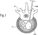
図1は、膨張可能構造体310を使用して処置されるべき椎骨41を示す。カニューレまたは脊麻針などの挿入装置200は、椎骨41の皮質骨69を通って延在し、海綿質骨71内に達している。膨張可能構造体310は、挿入装置200を通って椎骨41に導入され、望ましくは海綿質骨71内で膨張する。膨張可能構造体310は、一般には、外方に球形、円筒形などの形状に膨張して空洞を形成する。膨張した構造体310が皮質骨69に接触しないように、医師は一般に皮質骨69から十分離れた位置に挿入装置200を位置付けることによって、構造体310が外方に膨張する余地を設ける。ただし、挿入装置200を皮質骨69に近付けすぎた場合、または構造体が皮質骨69に向かって(海綿質骨がより脆弱な方向に)より大きく膨張した場合、または介在する生体組織によって挿入装置が皮質骨69に近い位置に押しやられる場合は、構造体の膨張および空洞の形成が最適に行われないこともある。
FIG. 1 shows a
図2および図7は、本発明の教示により構成された挿入装置の一実施形態を示す。挿入装置は、中空部材210を備える。中空部材210は何れか適切な形状にしうるが、円筒状であることが好ましい。中空部材210は、遠位端250と近位端255とを有し、遠位端250は挿入装置の先端部、つまり挿入ポイントである。中空部材210の長さは、処置を必要としている体内領域に挿入装置を経皮アクセスさせるために適切であれば何れの長さにもしうる。好適な一実施形態において、中空部材210の長さはほぼ12cmである。
2 and 7 illustrate one embodiment of an insertion device constructed in accordance with the teachings of the present invention. The insertion device includes a
中空部材210は、外科用器具および/または医療用材料が通過しうる適切な中心内径および肉厚を有する一方で、望ましくは骨などの体内領域への挿入中に変形に十分に耐えられる強度を有する。好適な一実施形態において、中空部材210の内径は0.3cm、肉厚は0.05cmである。さらに中空部材210は、ヒトまたは動物の体内での使用に適した何れの材料でも作製しうる。使用する材料として、(本明細書中に参考として援用される米国特許第6,036,711号に記載されているように)外科用ステンレス鋼、テフロン(登録商標)、ポリエチレン、ポリプロピレン、シリケート類、および液晶高分子類が挙げられるが、これだけに限定されるものではない。好適な一実施形態において、中空部材210はステンレス鋼製である。所望であれば、中空部材210を何れか適切な医療グレードの被膜でさらに被覆しうる。使用する被膜として抗感染性被膜、抗凝血性被膜、放出被膜、および/またはスリップ剤が挙げられるが、これだけに限定されるものではない。
The
一実施形態において、延長部分すなわちプラットフォーム220は、中空部材210の遠位端250から突出する。この実施形態において、プラットフォーム220は、中空部材210の壁から延在する半円筒形部分を備える。もちろん、プラットフォームは、図28に示す構成の1つまたは複数を含む、さまざまな構成で形成することもできる。好適な一実施形態において、プラットフォーム220は、中空部材210と同じ材料で作製される。もちろん、中空部材210に組み込まれている材料とは異なる材料でプラットフォーム220を作製および/または被覆することもできることが理解されるべきである。また、プラットフォーム220を中空部材210に一体化することもできる。たとえば、中空部材210の遠位先端部250に近い部分を切り取って、クレードル形状に残してもよい。または、溶接、接着など、当技術分野で周知のさまざまな手段によってプラットフォーム220を中空部材の遠位先端部250に取り付けてもよい。一実施形態において、プラットフォーム220は、挿入装置が軟質の組織および/または骨を通して導入されるときに座屈および/または著しい変形を生じない十分なカラム強度を有する。開示されている実施形態においては、中空部材210の遠位先端部250の部分を長手方向に二等分して取り除くことによって、残った半円筒状部分がプラットフォーム220を構成する。
In one embodiment, the extension or
望ましくは、プラットフォーム220が膨張可能構造体310と、椎骨41内の圧縮または作用されない領域との間に位置付けられるように、プラットフォーム220を膨張前の膨張可能構造体310の近くに配置する。構造体310の膨張に伴い、プラットフォーム220は膨張可能構造体310に対する支持体、土台、または障壁として機能し、1つまたは複数の方向への構造体310の膨張を抑止する。要するに、プラットフォーム220は、膨張可能構造体310がプラットフォーム220から離れる方向に膨張するように誘導する。挿入装置とプラットフォーム220とを皮質骨の内側に実質的に固定できるので、望ましくは、構造体の膨張の際に椎骨内でプラットフォーム220の剛性および/または不動状態が維持される。この構成によって、医師は膨張可能構造体310の膨張を椎骨の特定領域に向かわせることも、または特定領域から離れる方向に向かわせることもできる。
Desirably, the
図8に最もよく示されている別の実施形態において、プラットフォーム220は少なくとも1つの長手方向の折り目線225を備える。折り目線225はプラットフォームの中心近くに設けられることが好ましく、望ましくは、構造体310の膨張前、膨張中、または膨張後に、プラットフォーム220の少なくとも一部が折り目線225に沿って変形する。この実施形態では、プラットフォーム220を制御された方法で変形させることによって、プラットフォームを低プロファイル状態で容易に導入でき、プラットフォームをより大きい面積に変形させることによって構造体の膨張を最適に方向付け、さらにプラットフォームを低プロファイル状態で撤収できる。膨張可能構造体310の膨張に伴い、プラットフォーム220に圧力が加わると、折り目線225によってプラットフォーム220が制御された方法で容易に扁平化されるので、膨張可能構造体310の膨張を方向付けるために改良されたより広い支持面が用意される。支持面220の扁平化によってプラットフォーム220の縁端部も外方に向けて変形できるので、縁端部が鋭くても、膨張可能構造体310を損傷または破裂させる危険が減る。折り目線225は、機械的切断、レーザエッチング、溶接、鑞付け、または他の何れか周知の手段で形成しうる。
In another embodiment best shown in FIG. 8,
一代替実施形態においては、折り目線225によってプラットフォーム220を補強できるので、構造体220が膨張しているときのプラットフォーム220の変形を最小限に抑えることができる。たとえば、プラットフォーム220の丸みを帯びた底面をプラットフォームの長手方向軸に沿ってかしめるか、または曲げることによってプラットフォーム220を補剛してこの種の変形に耐えられるようにすることもできる。所望であれば、1つまたは複数の折り目線225を平行にかしめることもできる(図示せず)。一代替実施形態においては、かしめ部(図示せず)がプラットフォーム220の遠位先端部から近位側にほぼ7mm延在するので、プラットフォーム220のずれおよび/または変形が大幅に防止される。
In an alternative embodiment, the
別の代替実施形態においては、プラットフォームの遠位先端部に1つまたは複数の刻みまたは歯が組み込まれる。これらの刻みまたは歯は、遠位先端部から外方に広がっているため、対象となる骨領域の対向する皮質壁にプラットフォームを固着しやすくなる。この構成により、プラットフォームを両端で支持できるため、膨張可能構造体の膨張中のプラットフォームのずれおよび/または変形が大幅に防止される。 In another alternative embodiment, one or more indentations or teeth are incorporated into the distal tip of the platform. These indentations or teeth extend outward from the distal tip, making it easier to anchor the platform to the opposing cortical walls of the targeted bone region. This configuration allows the platform to be supported at both ends, thus greatly preventing platform displacement and / or deformation during expansion of the inflatable structure.
図11、図12、および図13に最もよく示されている別の実施形態において、プラットフォーム220は、中空部材210の遠位端250から延在する、比較的平らな部分を備える。好適な一実施形態においては、平らな天面212と、中空部材210と一体に形成された湾曲した外面213とをプラットフォーム220に組み込むことができる。この実施形態は中空部材210の内径をわずかに制約するが、プラットフォーム220の形状および肉厚の増加によってプラットフォーム220はより大きな外力に変形せずに耐えられる。また、この実施形態は、鋭い縁端部が膨張可能構造体に当たる可能性を最小限にする。さらに、扁平で厚みの増したプラットフォーム220は、図13に示すように、先端部を尖った形状にすることによって、プラットフォーム220が軟質の組織および/または骨を容易に貫通できるようになる。一代替実施形態において、膨張可能構造体の裂け、切れ、および/または他の破損を最小限にするために、可撓性および/または柔軟性を有する表面(図示せず)を膨張可能構造体および/またはプラットフォームの間に配置するか、あるいはプラットフォームまたは膨張可能構造体に組み込んでもよい。
In another embodiment best shown in FIGS. 11, 12, and 13, the
図29および図30は、本発明の教示により構成された挿入装置および関連の構成要素の一代替実施形態を示す。この実施形態において、挿入装置またはカニューレは、中空部材210を備える。中空部材210の形状は、適切なものであればいずれの形状でもよいが、円筒状であることが好ましい。中空部材210は遠位端250を有する。遠位端250は、挿入装置の先端部、すなわち挿入ポイントである。図29に最もよく示されている膨張ガイド400は、ハンドル組み立て体405とガイドシャフト410とを備える。ガイドシャフト410は、望ましくは中空部材210より長く、また望ましくは中空部材210の管腔を貫通できる寸法である。開示されている実施形態において、ガイドシャフト410の上面420は、望ましくはほぼ平らであり、ガイドシャフトの下面415は湾曲している。所望であれば、ガイドシャフトの向きと、中空部材の遠位端250からのガイドシャフトの延長距離とを示すために、1つまたは複数の位置合わせマーク407をハンドル組み立て体405および/またはガイドシャフト410に組み込むことができる。また、膨張ガイド400を中空部材210に固定するための機械式コネクタまたはクリップ(図示せず)をハンドル組み立て体に組み込んでもよい。
Figures 29 and 30 illustrate an alternative embodiment of an insertion device and associated components constructed in accordance with the teachings of the present invention. In this embodiment, the insertion device or cannula comprises a
この実施形態においては、対象の椎体内に挿入装置を位置付けた後で、海綿質骨を圧縮させたくない海綿質骨領域と膨張可能構造体との間にガイドシャフト410が位置付けられるように、膨張ガイド400を膨張前の膨張可能構造体(図示せず)の近くに配置することができる。所望であれば、膨張ガイド400を挿入装置に導入する前に、膨張可能構造体を挿入装置に導入することができる。構造体の膨張に伴い、ガイドシャフト410は膨張可能構造体に対する支持体、土台、または障壁として機能し、望ましくは1つまたは複数の方向への構造体310の膨張を抑止する。要するに、ガイドシャフト410は上記のプラットフォーム220と同様に機能し、膨張可能構造体310がガイドシャフト410から離れる方向に膨張するように誘導する。この構成によって、医師は膨張可能構造体の膨張を椎体の特定領域に向かわせることも、または特定領域から離れる方向に向かわせることもできる。また、中空部材内への膨張ガイド400の挿入深さを変えることができるので、医師は挿入装置の外に延在させるガイドシャフト410の望ましい長さを選択できる。一代替実施形態において、所望であれば、複数のプラットフォーム(図示せず)を使用して複数の方向を遮蔽できる。
In this embodiment, after positioning the insertion device within the vertebral body of interest, the
対象の椎体内に挿入装置を位置付けた後で膨張ガイド400を導入しうるので、軟質の組織および/または皮質骨に貫入するために十分なカラム強度を膨張ガイド400に持たせる必要がない。したがって、膨張ガイド400の断面を、図28に示す形態の1つまたは複数を含む、さまざまな形状にできる。
Since the
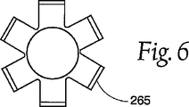
図3a、図4、および図6に最もよく示されている、本発明の教示により構成された挿入装置の別の代替実施形態において、挿入装置は、遠位端250と近位端255とを有する円筒状の中空部材210を備える。遠位端250は、挿入装置の先端部、すなわち挿入ポイントである。中空部材210の遠位端250には複数の切り込みが長手方向に付けられ、中空部材210の周縁の周りに複数の切り込み線260が形成されている。この複数の切り込み線260は、互いに平行に、または互いに角度をなして設けられ得、隣接区画265によって互いに隔てられている。切り込み線260の長さおよび深さは、隣接区画265に外方への圧力が加えられたときに遠位端250を張り出させる(図4および図6を参照)ために適切であれば何れの長さおよび深さにもしうる。
In another alternative embodiment of an insertion device constructed in accordance with the teachings of the present invention, best shown in FIGS. 3a, 4 and 6, the insertion device comprises a
好適な一実施形態において、切り込み線260は中空部材210の長手方向軸線に沿って、中空部材210の壁を貫いて約0.5cm延在する。切り込み線260は、当業者に公知の何れか適切な技術を用いて、遠位端250に切り込まれる。この技術として、レーザ切断またはエッチング、化学エッチング、および/あるいはカーバイドチップソー、ダイヤモンドチップソー、または高圧水による機械的切断が挙げられるが、これだけに限定されるものではない。中空部材210の遠位端250は、望ましくは、遠位端250の張り出しを容易にするために十分な数の長手方向切り込み線260を備える。適切な張り出しに必要な切り込み線260の数は、中空部材210の直径および肉厚と、材料の延性とによって決まる。本発明の一実施形態において、中空部材210は少なくとも3つの切り込み線260を遠位端250に備える。図6に最もよく示されている別の実施形態において、中空部材210は6つの切り込み線260を遠位端250に備える。
In a preferred embodiment, the
中空部材210の先端部が張り出すことによって、医療用バルーンなどの膨張可能構造体の挿入および撤収を容易にしうる。先端部を張り出すことによって、中空部材210の鋭い外縁部が膨張可能構造体から遠くに押しやられ、周囲の海綿質骨に押し込まれる。したがって、膨張中の膨張可能構造体がこれらの鋭い縁部から隔離されるため、膨張可能構造体がこれらの鋭い縁部に接触して、破裂したり、引き裂かれたりする危険が少なくなる。膨張可能構造体の撤収の間は、張り出した先端部の直径が大きいために、望ましくは膨張可能構造体が中空部材210の小さい直径の中に案内され、膨張可能構造体が中空部材210内へ容易に引き込まれて中空部材210内を後退する。
By protruding the distal end portion of the
所望であれば、膨張可能構造体を用いて所望の力を外向きに加えることによって先端部を張り出させることも、先端部を機械的に張り出させることもできる。たとえば、図3bに示す実施形態においては、隣接区画265のそれぞれの内面が肉厚化され、各隣接区画265から内側に延在する1つまたは複数の突起266が形成されている。所望であれば、突起266を遠位端250の周縁部を連続的に肉厚化した単一の領域として形成し、そこに長手方向の切り込み線260を入れることもできる。先の尖っていない閉塞具、穿孔部材、またはスタイレット275などのツールが、以下に説明するように、突起266を滑って越えるか、または突起266に押し付けられると、望ましくは隣接区画265が外方に押し出されて、中空部材210の遠位端250が所望の方法で張り出す。
If desired, the tip can be overhanged by applying a desired force outwardly using the inflatable structure, or the tip can be mechanically overhanged. For example, in the embodiment shown in FIG. 3b, the inner surface of each
本発明の挿入装置は、取り外し可能な尖っていない閉塞具またはスタイレット275をさらに備えうる。図5、図9a、図9b、図12、および図17を参照されたい。スタイレット275の遠位端279の先端部276は、尖っていても、または尖っていなくてもよい。所望であれば、当技術分野で周知のように、脊麻針組み立て体のガイドワイヤを収容するためにスタイレットを管状(図示せず)にすることができる。図15、図16a、および図17に最もよく示されている本発明の一実施形態においては、体内領域に挿入するために挿入装置を組み立てたときに、望ましくはスタイレット275の先端部276が中空部材210の遠位端250から延在する。スタイレット275は、望ましくは軟質組織および骨を突き通し、さらに/または切り開いて、挿入装置を所望の体内領域に配置できるトンネルまたは通路を形成する。所望であれば、スタイレット275は、挿入手順中に、当技術分野で周知の方法で、穿孔部材275を挿入装置に嵌合するための接合端(図示せず)をさらに備えることもできる。中空部材210をスタイレット275に接合することによって、望ましくは患者への挿入中にこれらの装置間のずれおよび相対移動が防止される。挿入装置を対象領域に配置した後でスタイレット275を中空部材210から容易に取り外せるように、スタイレット275が中空部材210に嵌合されることが好ましい。
The insertion device of the present invention may further comprise a removable non-pointed obturator or
スタイレット275は、何れか適切な医療グレード材料で作製しうるが、中空部材210と同じ材料で作製することが好ましい。好適な一実施形態において、スタイレット275は、ステンレス鋼製である。さらにスタイレット275は、中空部材210の中を摺動でき、中空部材210に嵌る形状およびサイズであれば、何れか適切な形状およびサイズにしうる。好適な一実施形態において、スタイレット275は、中空部材210とほぼ同じ円筒形状であり、中空部材210よりわずかに長く、挿入用に組み立てたときに先端部276が中空部材210の遠位端250から突出し、スタイレット275が中空部材210の中を自由に摺動して挿入および取り出しが容易なように直径が中空部材210の穴の内径よりわずかに小さい。
The
図15、図16a、図16b、および図17に示されている本発明の一実施形態において、スタイレット275の遠位端279は、望ましくは、先端部276の近くに1つまたは複数の溝または窪み273を有する。好適な一実施形態において、窪み273はスタイレット275の遠位端279の周縁を一周する連続した窪みである。少なくとも1つの窪み273を遠位端279に有するスタイレット275は、図3b、図5、および図17に示すように、複数の長手方向の切り込み線260と1つまたは複数の突起266とをその遠位端250の各隣接区画265に有する中空部材210との嵌合に適している。このような挿入装置を組み立てるとき、遠位端279が中空部材210から外に延在するまで、スタイレット275を中空部材210に挿入することができる。次に隣接区画265を内側に折り畳むか、またはかしめると、突起266がスタイレット275の窪み273に入り込むので、挿入装置の挿入前に、中空部材210の外壁が比較的円筒状になる。挿入装置を所望の体内領域で適所に配置した後で、スタイレット275を中空部材210から引き抜くと、1つまたは複数の突起266が張り出して、スタイレット275の遠位端279が外方に押し出される。別の実施形態においては、遠位端250の張り出しを容易にするために、1つまたは複数の突起266に隣接するカラー部267が、中空部材210の壁の残りの部分より薄くなっている。
In one embodiment of the invention shown in FIGS. 15, 16a, 16b, and 17, the
図9a〜9cに最もよく示されている、本発明の教示により構成された挿入装置の別の実施形態において、挿入装置は、プラットフォーム220と、複数の長手方向の切り込み線260で分けられた1つまたは複数の隣接区画とを遠位端250に有する中空部材210を備える。別の実施形態において、このタイプの挿入装置は、少なくとも1つの窪み273を先端部276近くに有するスタイレット275をさらに備える。スタイレット275によって隣接区画265の1つまたは複数の突起266に外方への圧力をかけることによって、プラットフォーム220の近くで遠位端250を張り出させることができる。本発明の挿入装置のこのような好適な実施形態では、使用者が医療用バルーンなどの膨張可能構造体の膨張を方向付けることができるばかりでなく、膨張可能構造体の挿入および撤収を容易に行え、膨張可能構造体を損傷するリスクも減る。
In another embodiment of an insertion device constructed best in accordance with the teachings of the present invention, best shown in FIGS. 9a-9c, the insertion device is divided by a
本発明は、開示されている各挿入装置を使用して、膨張可能構造体の膨張を方向付けるため、ならびに/またはヒトまたは動物の体内領域への膨張可能構造体の挿入および撤収を容易に行うための方法をさらに提供する。例示を目的として、骨粗しょう症の脊椎固定、すなわち椎体内への挿入および膨張のための方法を説明する。ただし、同様の方法は、ヒトまたは動物の体内の適切な領域であれば何れの領域にも使用しうる。 The present invention uses each disclosed insertion device to direct the expansion of the inflatable structure and / or to facilitate the insertion and withdrawal of the inflatable structure into a human or animal body region. A method is further provided. For purposes of illustration, a method for osteoporotic spinal fixation, ie, insertion and expansion into the vertebral body, is described. However, the same method can be used for any suitable region within the human or animal body.
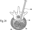
図18〜27に示されているように、本発明の一実施形態においては、患者10の背中が露出するように、患者10をほぼU字形状のホルダ15に載せる。外科的手順中に医師が挿入装置の挿入および配置を視認できるX線、CATスキャン、MRI、フルオロスコープ、または他の適切な装置20を患者の周囲に配置してもよい。上記のように、中空部材210にスタイレット275を取り付けた状態の挿入装置200を軟組織を通して椎体に導入できる。挿入装置200の位置はX線透視で突き止めることができる。望ましくは、スタイレットと挿入装置とを椎体30の皮質骨31に貫通させ、その後スタイレット275を取り出すことができる。中空部材210が1つまたは複数の隣接区画265を有し、複数の隣接区画265が複数の長手方向の切り込み線260で分けられている、挿入装置の一実施形態においては、スタイレット275を取り除くと、図22に示すように、望ましくは中空部材210の遠位端250が張り出す。
As shown in FIGS. 18 to 27, in one embodiment of the present invention, the
医療用バルーンなどの膨張可能構造体50を中空部材210を通して椎体30に挿入することができる。膨張可能構造体50の配置は、X線透視法またはリアルタイムMRIを含む、何れか適切な手段によって監視できる。膨張可能構造体50を膨張すると、空洞55が海綿質骨32内に形成され、さらに/または皮質骨31が移動する。その後、膨張可能構造体50を収縮させて取り除く。中空部材210の遠位端250が張り出した一実施形態においては、張り出した端部によって構造体50が中空部材210内に案内される。次に空洞55に適切な骨充填材60を充填できる。
An
本発明の別の好適な実施形態においては、中空部材210の遠位端250からプラットフォーム220が延在する。図24〜27を参照されたい。中空部材210を椎体30内に導入したら、構造体50を膨張させたくない椎体領域がプラットフォーム220によって遮蔽されるまで、中空部材210を回転させることができる。構造体50が膨張するとき、プラットフォーム220から離れる方向に構造体50が膨張するようにプラットフォーム220によって膨張が誘導される。このように、挿入装置を位置付けた椎体内の場所にほぼ関係なく、空洞に適した領域が形成される。したがって、挿入装置を位置付けた椎体内の場所が空洞の形成に最適でなくても、挿入装置全体を捻ったり、曲げたり、または他の方法で位置調整を行うことなく、挿入装置200を単に回転させて、空洞形成に望ましい方向にプラットフォーム220を向かせるだけでよい。望ましくは、中空部材210のハンドルまたは近位部に設けられたインジケータ(図示せず)によって、骨内のプラットフォームの向きが医師に示される。同様に、より大きい空洞または非対称的な空洞が望ましい場合は、構造体50の膨張によって第1の空洞を形成した後で、構造体50を収縮させ、挿入装置200を回転させてプラットフォーム220を別の方向に向かせてから、同一または別の構造体50を膨張させることによって図25に示すような第2の空洞などを形成してもよい。この方法によって、任意の所望の数および/または寸法の空洞を形成しうる。別の実施形態においては、形状が異なる複数のバルーンを挿入することによってそれぞれ異なる空洞を形成してもよく、あるいは形状が異なる複数の膨張可能構造体を用いて各空洞を形成してもよい。
In another preferred embodiment of the present invention, the
所望の空洞55が1つまたは複数形成されたら、膨張可能構造体50を収縮させ、中空部材210を通して取り出し得る。中空部材210の遠位端250が張り出す実施形態においては、張り出した先端部によって構造体が中空部材210内に導かれるので、収縮した構造体の撤収をより容易に行える。適した骨補填材、たとえばポリメタクリル酸メチル骨セメント、二液型ポリウレタン材料、または他の何れか適切な生体適合性の骨充填材60などを、形成された1つまたは複数の空洞55内に注入する。一実施形態においては、第1の空洞55を形成し、所望であれば、この空洞55を少なくとも部分的に骨充填材60で充填してから、同一または別の膨張可能構造体50を同じ空洞55内に挿入して膨張することによって、硬化用骨充填材および/またはより海綿質の骨32を緻密化し、次に空洞55を同一または別の骨充填材60でさらに充填してもよい。別の実施形態においては、第1の空洞55を形成し、次にプラットフォーム220付きの挿入装置200を回転させ、同一または別の膨張可能構造体50を挿入して第2の空洞を形成するか、または第1の空洞55を拡大し、次に1つまたは複数の空洞を同一または別の骨充填材60で充填してもよい。所望の空洞がすべて形成されて充填されるまで、これらの方法を続けてもよい。
Once one or more desired
所望の空洞がすべて充填されたら、挿入装置200を椎体30から取り除き得る。次に、切開部25を縫い合わせて閉じ、さらに/または包帯で覆い得る。
Once all the desired cavities are filled, the
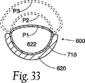
図31〜33は、本発明の教示により構成された挿入装置600の一代替実施形態を示す。挿入装置600は、中空部材620と膨張可能構造体710とを備える。ツールの操作および/または膨張可能構造体710を膨張するための媒質の導入を容易にするために、ハンドル615を中空部材620の遠位端に設けてもよい。中空部材620は、望ましくは管腔622が貫通しており、シャフト624と遠位先端部625とを備える。シャフト624の遠位端625は、皮質/海綿質骨を貫通しやすくするために丸みまたは斜角を付けることも、あるいは対象の骨領域の反対側の皮質壁に貫入する機会を最小限にするために平らにすることもできる。開口部すなわち窓700をシャフト624に形成し、望ましくは管腔622内に窓700に隣接させて膨張可能構造体710を位置付ける。挿入装置600を対象の骨領域(図示せず)に導入したら、膨張可能構造体710を膨張することができる(図33をP1、P2、P3の順に参照されたい)。膨張可能構造体710の少なくとも一部が望ましくは窓700を通って膨張し、海綿質骨を圧縮し、空洞を形成し、さらに/または皮質骨を移動させる。膨張可能構造体710の収縮後は、望ましくは膨張可能構造体710の大半が管腔622内に引き込まれ、装置600を椎体から撤収できるようになる。所望であれば、対象の骨領域内での窓700の向きを示すマーキング(図示せず)をハンドル615および/または中空部材620の近位端612に設けることができる。
31-33 illustrate an alternate embodiment of an
膨張可能構造体710は、医療用装置で一般に使用される可撓性材料で構成しうる。使用可能な可撓性材料として、プラスチック、ポリエチレン、マイラー、ゴム、ナイロン、ポリウレタン、金属、または複合材料が挙げられるが、これだけに限定されるものではない。シャフト624は、望ましくは、膨張可能構造体710の材料より高い耐膨張性を有する材料で構成される。シャフト624の材料として、ステンレス鋼、セラミック、複合材料および/または硬質プラスチックが挙げられるが、これだけに限定されるものではない。一代替実施形態においては、膨張可能構造体710およびシャフト624に同様の材料を使用しうるが、厚さおよび/または量を違えることによって、膨張可能構造体710をシャフト624より膨張し易くしうる。膨張可能構造体710を、当技術分野で周知のさまざまな手段によって、シャフト624に直接接合してもよい。使用可能な手段として、溶接、溶融、接着などが挙げられるが、これだけに限定されるものではない。複数の代替実施形態においては、膨張可能構造体をシャフト624の内側または外側に、あるいはこれらの組み合わせに固定してもよい。少なくとも1つの代替実施形態においては、膨張可能構造体710の膨張に伴い、膨張可能構造体710を構成する材料の少なくとも一部が塑性変形する。
The
所望であれば、シャフト624は、対象の骨領域内に既に位置付けられているカニューレまたは脊椎アクセス針(図示せず)の管腔を通過するサイズにしうる。あるいは、挿入装置600のこの実施形態を、対応する挿入装置なしに使用できる。このような場合は、望ましくは、椎体の軟組織および皮質/海綿質骨に貫入可能な尖った遠位先端部625を挿入装置600に組み込む。遠位先端部は、装置600の所望の貫入強度に応じて、中空または中実構造にしうる。同様に、膨張可能構造体710のサイズおよび構成と、装置の所望の貫入強度とに応じて、窓700が占めるシャフト624の外周範囲を拡大または縮小しうる。たとえば、窓700がシャフト624の周囲のほぼ25%にわたる場合は、窓がシャフト624のほぼ75%にわたる場合に比べ、装置600の貫入強度が極めて大きくなる。所望であれば、装置600を対象の骨領域に配置する際の整形外科用木槌の使用を容易にするために衝撃面(図示せず)をハンドル615に組み込むことができる。一代替実施形態においては、空洞の形成後に、膨張可能構造体を中空部材600から取り除くことができるので、骨充填材を中空部材を通して空洞に導入できる。
If desired, the
図34〜36は、本発明の代替実施形態により構成された膨張ガイド800の別の代替実施形態を示す。この実施形態において、プラットフォーム810は、中空部材820の壁から延在する半円筒形区画を備える。切り欠き825がプラットフォーム810に沿って長手方向に延在している。切り欠き825は、膨張可能構造体のキーまたは突起(図示せず)を収容することによって、望ましくは膨張可能構造体をプラットフォーム810に固定する。
FIGS. 34-36 show another alternative embodiment of an
周囲の海綿および/または皮質骨の質および強度によっては、膨張可能構造体が膨張してプラットフォーム810を押すときに、膨張可能構造体がプラットフォーム810から「滑り落ちる」ことがある。同様に、プラットフォームの回転によって、膨張可能構造体が望ましくない方法でずれることもある。望ましくは、切り欠き825によって構造体がプラットフォーム810に固定され、上記のような現象が防止される。また、構造体を収縮させるとき、膨張している構造体をプラットフォーム810に対して正しい向きで引き込むために切り欠き825は使用される。
Depending on the quality and strength of the surrounding sponge and / or cortical bone, the inflatable structure may “slide” off the
図37〜39は、図34のプラットフォーム810の一製造方法を示す。この実施形態においては、長手方向の線Aに沿ってシャフト820の遠位端に切り込みを入れる。あるいは、切り欠きの所望のサイズおよび切り欠きの側壁の所望の角度によっては、シャフト820を長手方向の線Bに沿って切り取ってもよい。シャフトをスタンピング機850に置き、ダイ860によってシャフト820の切り込みの入った壁821をシャフト820の対向する壁822に押し付ける。望ましくは、切り込みの入った壁821が対向する壁822に接触し、切り込みの入った壁821と対向する壁822とによって切り欠き825が形成される。
37-39 show one manufacturing method for the
同様の方法によって、図29および図30に記載の実施形態の挿入装置に切り欠きを形成し、この切り欠きによって膨張可能体を案内し、プラットフォームに固定することもできる。プラットフォームが対象の骨領域内に位置付けられたら、プラットフォームを、そこに固定された膨張可能構造体と共に、操作および/または回転することもできる。したがって、この実施形態では、膨張可能構造体を極めて容易にプラットフォーム上に所望の向きで正しく配置できる。所望であれば、成形、研削、打ち抜き、または当業者に公知の何れか他の機械加工方法によって切り欠きを形成することもできる。 In a similar manner, a notch can be formed in the insertion device of the embodiment described in FIGS. 29 and 30, and the inflatable body can be guided and secured to the platform by this notch. Once the platform is positioned within the bone region of interest, the platform can also be manipulated and / or rotated with the inflatable structure secured thereto. Thus, in this embodiment, the inflatable structure can be placed on the platform in the desired orientation correctly with great ease. If desired, the notches can be formed by molding, grinding, stamping, or any other machining method known to those skilled in the art.
図40〜50は、バルーンカテーテル装置900の別の代替実施形態を示す。装置900は、シースすなわち中空部材902を備える。中空部材902は、バルーンカテーテル903を収容するサイズと構成とを有する。バルーンカテーテル903は、シャフト906によって担持される膨張可能構造体904と、先の尖っていない、球形の探査用先端部910を備えたスタイレット908とを含む。図示の実施形態において、中空部材902は、バルーンカテーテル903の外部シースを形成するカニューレの形態を採る。中空部材902は、ステンレス鋼または他の何れか適した生体適合材料で形成しうる。装置900の操作および/または膨張可能構造体904を膨張するための媒質の導入を容易にするために、ハンドル912、たとえばYアダプタ、を中空部材902の近位端914に設けてもよい。
40-50 illustrate another alternative embodiment of a
シャフト906は、望ましくは、スタイレット908を通過させうるサイズと構成とを有する。中空部材902内の膨張可能構造体904をさらに支持および安定化するために、スタイレット908は、膨張可能構造体904の長さ全体にわたって膨張可能構造体904を支持する。スタイレット908は、何れか適切な医療グレードの材料で製造されうるが、中空部材902と同じ材料、たとえばステンレス鋼、で製造することが好ましい。好適な一実施形態において、スタイレット908は、シャフト906とほぼ同じ円筒形状であり、シャフト906よりわずかに長く、挿入用に組み立てたときに先端部910がシャフト906の遠位端916から突出し、シャフト906の中を自由に摺動できるようにスタイレット908の直径はシャフト906の穴の内径よりわずかに小さい。スタイレット908には、Yアダプタ912をさらに固定できる。この場合、Yアダプタ912のルアーロック909を、UV硬化型接着剤、熱、超音波、またはシアノアクリレート接着接合などによってスタイレット908に接合する。所望であれば、当技術分野で周知のように、脊麻針組み立て体のガイドワイヤを収容するためにスタイレット908を管状(図示せず)にすることができる。
The
中空部材902は、望ましくは管腔918が貫通しており、シャフト920と遠位先端部922とを備える。中空部材902の遠位先端部922は、中空部材902内での膨張可能構造体904の移動を防ぐ固定要素を少なくとも1つ含む。図示の実施形態においては、一対の固定要素が設けられている。これらの固定要素は翼付きタブ924の形態を採る。
The
開口部または窓のプラットフォーム926を翼付きタブ924に隣接させてシャフト920に形成し、膨張可能構造体904を管腔918内に、望ましくは窓926に隣接させて配置する。膨張可能構造体904の膨張を方向付けるために、窓926は、中空部材902の軸線に沿って、かつ中空部材902の軸線を中心として望ましくは360°未満の範囲にわたって延在させる。窓926は、中空部材902の軸線を中心として望ましくは180°未満の範囲にわたって延在させ、好ましくは90°と180°との間で延在させる。代表的な一実施形態において、窓は中空部材902の軸線を中心としてほぼ135°の範囲にわたって延在する。窓926が小さいほど、膨張可能構造体904の膨張の方向性およびプラットフォーム926の強度が増す。
An opening or
代表的な一実施形態において、装置900は以下の寸法を含む。
In one exemplary embodiment, the

図示の好適な実施形態において、膨張可能構造体904は、シャフト906に対して接線方向に担持される。膨張可能構造体904の方向性は、ハンドル912上の外部マーカ911によって、またはハンドル912の方向性によって示されうる。
In the preferred embodiment shown, the
外部マーカ911は、Yアダプタ912および中空部材902に取り付けられたひずみリリーフ913上に担持される。外部マーカ911は、方向性を示すために翼または張り出しが付いており、Yアダプタ912のサイドポートまたは膨張用アーム、および窓926に位置揃えされている。ひずみリリーフ913はさらに、中空部材902とYアダプタ912との結合部における中空部材902のねじれを防ぎ、結合部を固定している接着剤を覆うという役割もある。マーカの位置、種類、および数に関して、さまざまな方向性構成、マーキング、またはこれらの組み合わせを組み込んでマーカにさまざまな変更を加えることも考えられている。
The
膨張可能構造体904を窓926内に配置するには、スタイレット908をシャフト906の遠位端916から近位端917に通すことによって膨張可能構造体904を貫通させ、膨張可能構造体904付きのシャフト906とスタイレット908とを中空部材902の遠位先端部922から近位端914に通す。スタイレットのボール910は中空部材902の遠位先端部922に接触し、組み立て体の一部として永久的に統合されうる。Yアダプタ912は、上記のように、スタイレット908および中空部材902に結合される。所望であれば、Yアダプタ912への中空部材902の結合を容易にするために、中空部材902の近位端914を遠位端922に対して相対的に先細りにしてもよい。
To place the
膨張可能構造体904を窓926内に確実に位置付けるために、シャフト906の遠位端916に沿ってタブ924をかしめるか、または内側に折り曲げる。タブをかしめるか、または折り曲げることによって、中空部材902がシャフト906に固定されるので、膨張中の膨張可能構造体904の上昇および移動が防止される。
To ensure that the
翼付きタブ924をかしめると、図43に示すように、翼付きタブ924が先細りになり、遠位先端部922全体が低プロファイル化する。先細りなった先端部922によって、装置900を骨により容易に、より低外傷的に挿入できるようになる。先細りになった先端部922は低プロファイル化されているので、膨張したバルーン材料のランディングゾーンとしても機能する。膨張可能構造体904の膨張後、膨張したバルーン材料は塑性変形するので、膨張可能構造体904の成形モルフォロジーが変化する。膨張したバルーン材料は、その本来の形状に完全には戻らないこともあり、一部が窓926から外方に延在することもある。先細りになった先端部922は、翼付きタブ924全体を越えた膨張バルーン材料の膨張を可能にし、アクセスカニューレを通しての装置900の撤収中における膨張可能構造体904の団子状化または裂け傷が防止されるので、引き込み力が軽減される。図示の実施形態においては2つのタブ924が図示されているが、タブ924の数および構成は可変であると考えられている。
When the
翼付きタブ924は、図44に示すように、かしめた状態で目に見える間隙Gが設けられるようにしうる。間隙Gは、膨張したバルーン材料のためにさらなるランディングゾーンを提供する。図45に示す一代替実施形態においては、かしめられた状態で翼付きタブ同士924が接触し、目に見える間隙Gがないようになっている。
The
図46〜48は、シャフト906の遠位端916とスタイレットの先端部910とを中空部材902の遠位先端部922より先まで延在させることによって、膨張したバルーン材料のためにさらなるランディングゾーンを提供する一代替実施形態を示す。
46-48 illustrate additional landing zones for inflated balloon material by extending the
スタイレットの先端部910によって、装置900を皮質壁プローブとして使用できるため、前方の皮質壁を破ることなく装置900を椎体30内に前進させ、最適に前方に配置できる。先端部910は尖っていないため、椎体30の前方の皮質壁に突き刺さりにくい。医師は、尖っていない遠位先端部910と皮質前壁との間の接触を触覚的に感知するまで、装置900をアクセス開口部を通して海綿質骨32に前進させる。
Because the
望ましくは、海綿質骨32を通してのスタイレット908の前進およびスタイレット908と椎体30内の皮質前壁との接触を、たとえばX線またはリアルタイム透視またはMRIによって視認できるように、スタイレット908は放射線不透過性である。したがって、スタイレット908によって、医師は椎体30内へのアクセス開口部と皮質前壁との間の距離を正確に測定できるので、皮質壁への貫入を防ぐことができる。
Desirably, the
椎体30の前方の皮質壁を突き破った場合、または突き破った恐れがある場合、医師はスタイレットの先端部910を用いて壁の破れた箇所の有無および/または範囲を安全かつ容易に判定することができる。スタイレット908の先端部910が尖っていないために、望ましくは先端部910は無傷の皮質前壁を容易には貫通しない。したがって、医師は前方の皮質壁の内面に沿って装置で「打診」することによって破れ目を探すことができる。壁が破れていた場合、および装置900がその破れ目を貫通しうる場合でも、望ましくはスタイレット908の尖っていない先端部910は、皮質壁の前方に位置する大動脈または主要な静脈などの軟組織を突き刺したり、損傷したりすることはない。あるいは、所望であれば、尖っていない先端部910をゴムまたはプラスチックなどの軟質の変形可能な材料で形成することもできる。
If the cortical wall in front of the
使用時は、図49に示すように、カニューレ928を挿入するために、対象の骨領域内へのアクセス開口部を従来の技術で形成する。次に、医師は装置900を対象の骨領域、たとえば椎体30の内部に位置付けられているカニューレ928の管腔に通す。
In use, as shown in FIG. 49, an access opening into the target bone region is formed by conventional techniques for insertion of a
図50に示されているように、次に膨張可能構造体904を膨張させ、空洞55を海綿質骨32内に形成し、さらに/または皮質骨31を移動させ、その後に膨張可能構造体904を収縮させる。図51は、正常な椎体30を示す。所望の位置に移動させたい皮質骨31の区画(たとえば楔状椎(図52)、魚椎(図53)、または扁平椎(図54)などの骨折形態など、椎体30の上面または下面の窪み)に膨張可能構造体904の膨張が窓926によって方向付けられるように装置900を位置付ける。膨張可能構造体904をさらに回転させるか、あるいは前方または後方に再配置し、膨張させて所望の空洞を形成してもよい。次に、膨張可能構造体904を潰して取り除く。次に空洞55に適切な骨充填材60を充填することができる。
As shown in FIG. 50, the
開示されている装置および方法はヒトの椎骨の処置という文脈でより具体的に説明されているが、ヒトまたは動物の他の種類の骨も同じまたは同等の方法で処置することができる。限定ではなく一例として、本システムおよび方法は、骨髄をその中に有する骨であれば何れの骨にでも使用できる。対象となる骨として橈骨、上腕骨、脊椎、大腿骨、脛骨、または踵骨が挙げられるが、これだけに限定されるものではない。 Although the disclosed devices and methods are more specifically described in the context of the treatment of human vertebrae, other types of human or animal bones can be treated in the same or equivalent manner. By way of example and not limitation, the present systems and methods can be used with any bone having bone marrow therein. The bones of interest include, but are not limited to, ribs, humerus, spine, femur, tibia, or ribs.
本明細書の検討および本願明細書に開示されている本発明の実施によって、当業者には本発明の他の実施形態および使用法が明らかになる。本願明細書で参照しているすべての文献は、参照によって個別にその全内容を本願明細書に引用したものとする。本明細書および実施例は単に例示を目的としたものと考えられるべきであり、本発明の範囲および精神は添付の特許請求の範囲によって示されるものである。当業者には容易に理解されるように、開示されている各実施形態のさまざまなバリエーションおよび変更は、これらの組み合わせを含め、付属の特許請求の範囲によって定義されている本発明の範囲内で容易に行うことができる。 Other embodiments and uses of the invention will be apparent to those skilled in the art from consideration of the specification and practice of the invention disclosed herein. All documents referred to in this specification are hereby incorporated by reference in their entirety. It should be understood that the specification and examples are for purposes of illustration only, and the scope and spirit of the invention is indicated by the appended claims. As will be readily appreciated by those skilled in the art, various variations and modifications of each disclosed embodiment, including combinations thereof, are within the scope of the invention as defined by the appended claims. It can be done easily.
Claims (15)
膨張可能構造体と、
前記膨張可能構造体を収容するシースであって、前記膨張可能構造体の膨張を方向付けるために前記シースの軸線に沿って、かつ前記シースの軸線を中心として延在する開口部と、前記膨張可能構造体を前記シース内に固定する少なくとも1つの固定要素とを含むシースと、を備え、
前記固定要素がタブであって、前記タブが先細りになっている装置。A bone treatment device,
An inflatable structure;
A sheath for accommodating the inflatable structure, the opening extending along an axis of the sheath and about the axis of the sheath to direct expansion of the expandable structure; A sheath including at least one anchoring element that anchors a possible structure within the sheath ;
The device wherein the securing element is a tab and the tab is tapered .
前記開口部が前記シースの軸線に沿って、かつ前記シースの軸線を中心として360°未満の範囲にわたって延在する装置。The apparatus of claim 1, comprising:
A device wherein the opening extends along an axis of the sheath and over a range of less than 360 ° about the axis of the sheath.
前記膨張可能構造体が海綿質骨を圧縮するようになっている装置。The apparatus of claim 1, comprising:
A device wherein the inflatable structure is adapted to compress cancellous bone.
遠位端を有するスタイレットであって、前記膨張可能構造体を貫通して延在するサイズと構成とを有し、前記スタイレットの遠位端が少なくとも部分的に前記シースの遠位端を越えて延在するスタイレットをさらに備える装置。The apparatus of claim 1, comprising:
A stylet having a distal end, the stylet having a size and configuration extending through the inflatable structure, wherein the distal end of the stylet at least partially defines the distal end of the sheath. The apparatus further comprising a stylet extending beyond.
前記スタイレットの遠位端が尖っていない装置。The apparatus according to claim 4 , comprising:
A device wherein the distal end of the stylet is not pointed.
軸線に沿って延在し、遠位端を有するシースと、
遠位端を備え、前記シースを貫通する形状と構成とを有するシャフトと、
尖っていない遠位端を備え、前記シャフトを貫通するサイズと構成とを有するスタイレットであって、前記尖っていない遠位端が少なくとも部分的に前記シースの遠位端および前記シャフトの遠位端を越えて延在するスタイレットと、を有し、
前記シースが、前記シース内での前記シャフトの移動を防ぐ固定要素を少なくとも1つ含み、前記固定要素がタブであって、前記タブが先細りになっている皮質骨壁プローブ。A cortical bone wall probe,
A sheath extending along an axis and having a distal end;
A shaft having a distal end and having a shape and configuration extending through the sheath;
A stylet having a non-pointed distal end and sized and configured to penetrate the shaft, wherein the non-pointed distal end is at least partially distal to the sheath and distal to the shaft possess a stylet extending beyond the end of,
A cortical bone wall probe wherein the sheath includes at least one anchoring element that prevents movement of the shaft within the sheath, the anchoring element being a tab and the tab being tapered .
前記シャフトによって担持される膨張可能構造体をさらに備え、
前記膨張可能構造体の膨張を方向付けるために、前記シースが前記シースの軸線に沿って、かつ前記シースの軸線を中心として延在する開口部を含む皮質骨壁プローブ。The cortical bone wall probe according to claim 6 ,
Further comprising an inflatable structure carried by the shaft;
A cortical bone wall probe, wherein the sheath includes an opening extending along an axis of the sheath and about the axis of the sheath to direct expansion of the expandable structure.
前記膨張可能構造体が、前記開口部の外側に、前記シースを越えて膨張するようになっている皮質骨壁プローブ。The cortical bone wall probe according to claim 7 ,
A cortical bone wall probe wherein the inflatable structure is adapted to expand beyond the sheath outside the opening.
前記膨張可能構造体の膨張を方向付けるために、前記開口部が前記シースの軸線に沿って、かつ前記シースの軸線を中心として360°未満の範囲にわたって延在する皮質骨壁プローブ。The cortical bone wall probe according to claim 7 ,
A cortical bone wall probe, wherein the opening extends along an axis of the sheath and over a range of less than 360 degrees about the axis of the sheath to direct expansion of the expandable structure.
前記膨張可能構造体が海綿質骨を圧縮するようになっている皮質骨壁プローブ。The cortical bone wall probe according to claim 7 ,
A cortical bone wall probe wherein the expandable structure is adapted to compress cancellous bone.
内部を貫通する管腔と遠位端とを有するシャフトによって担持される膨張可能構造体と、
尖っていない遠位先端部を備えたスタイレットであって、バルーンカテーテル組み立て体を形成するために、前記尖っていない遠位先端部の少なくとも一部を前記シャフトの遠位端より先に延在させるために、前記管腔を貫通するサイズと構成とを有するスタイレットと、
遠位端を備え、前記カテーテル組み立て体を通過させるサイズと構成とを有するシースであって、前記膨張可能構造体を受け入れるための開口部と、前記シースを前記シャフトの遠位端に固定するための少なくとも1つの固定要素とを含むシースと、を備え、
前記固定要素がタブであって、前記タブが先細りになっている装置。A bone treatment device,
An inflatable structure carried by a shaft having a lumen therethrough and a distal end;
A stylet with an unsharp distal tip that extends at least a portion of the non-sharp distal tip beyond the distal end of the shaft to form a balloon catheter assembly A stylet having a size and configuration that penetrates the lumen;
A sheath having a distal end and sized and configured to pass through the catheter assembly; and an opening for receiving the inflatable structure; and securing the sheath to the distal end of the shaft and a sheath comprising at least one fixed element of,
The device wherein the securing element is a tab and the tab is tapered .
前記スタイレットの遠位先端部が少なくとも部分的に前記シースの遠位端を越えて延在する装置。The apparatus of claim 11 , comprising:
The device wherein the distal tip of the stylet extends at least partially beyond the distal end of the sheath.
皮質骨領域を通して前記骨の海綿質骨領域に導入されるように構成されている挿入装置と、
前記挿入装置を通して導入されるように構成されているバルーンカテーテル組み立て体であって、前記バルーンカテーテル組み立て体が膨張可能構造体と、前記膨張可能構造体を収容するシースとを備え、前記シースが前記シースの軸線に沿って、かつ前記シースの軸線を中心として延在する、前記膨張可能構造体の膨張を方向付けるための開口部と、前記膨張可能構造体を前記シース内に固定する少なくとも1つの固定要素とを含むバルーンカテーテル組み立て体と、
空洞を前記骨内に形成するために、前記膨張可能構造体を前記開口部の外側に、前記シースを越えて膨張させるための手段と、を備え、
前記固定要素がタブであって、前記タブが先細りになっているシステム。A system for treating bone,
An insertion device configured to be introduced through the cortical bone region into the cancellous bone region of the bone;
A balloon catheter assembly configured to be introduced through the insertion device, the balloon catheter assembly comprising an inflatable structure and a sheath for housing the inflatable structure, wherein the sheath An opening for directing expansion of the inflatable structure extending along and around the axis of the sheath, and at least one securing the expandable structure within the sheath A balloon catheter assembly including a securing element;
Means for inflating the expandable structure outside the opening and beyond the sheath to form a cavity in the bone ;
A system in which the securing element is a tab and the tab is tapered .
前記膨張可能体の膨張によって海綿質骨が圧縮されるシステム。14. The system according to claim 13 , wherein
A system in which cancellous bone is compressed by expansion of the expandable body.
前記空洞に充填するための骨充填材をさらに備えるシステム。14. The system according to claim 13 , wherein
The system further comprising a bone filler for filling the cavity.
Applications Claiming Priority (3)
| Application Number | Priority Date | Filing Date | Title |
|---|---|---|---|
| US10/848,514 US7815649B2 (en) | 2000-04-07 | 2004-05-18 | Insertion devices and method of use |
| US10/848,514 | 2004-05-18 | ||
| PCT/US2005/016654 WO2006007090A2 (en) | 2004-05-18 | 2005-05-12 | Insertion devices and method of use |
Publications (3)
| Publication Number | Publication Date |
|---|---|
| JP2008504941A JP2008504941A (en) | 2008-02-21 |
| JP2008504941A5 JP2008504941A5 (en) | 2008-06-26 |
| JP4904271B2 true JP4904271B2 (en) | 2012-03-28 |
Family
ID=35784284
Family Applications (1)
| Application Number | Title | Priority Date | Filing Date |
|---|---|---|---|
| JP2007527309A Expired - Fee Related JP4904271B2 (en) | 2004-05-18 | 2005-05-12 | Insertion device and method of use |
Country Status (8)
| Country | Link |
|---|---|
| US (1) | US7815649B2 (en) |
| EP (1) | EP1768737A4 (en) |
| JP (1) | JP4904271B2 (en) |
| KR (1) | KR101179856B1 (en) |
| CN (1) | CN101384223B (en) |
| AU (1) | AU2005262796B2 (en) |
| CA (1) | CA2567381A1 (en) |
| WO (1) | WO2006007090A2 (en) |
Families Citing this family (176)
| Publication number | Priority date | Publication date | Assignee | Title |
|---|---|---|---|---|
| US20030229372A1 (en) * | 1994-01-26 | 2003-12-11 | Kyphon Inc. | Inflatable device for use in surgical protocols relating to treatment of fractured or diseased bone |
| ES2287635T3 (en) * | 1994-01-26 | 2007-12-16 | Kyphon Inc. | IMPROVED FLAMMABLE DEVICE FOR USE IN SURGICAL METHODS RELATED TO BONE FIXATION. |
| US20060100635A1 (en) * | 1994-01-26 | 2006-05-11 | Kyphon, Inc. | Inflatable device for use in surgical protocol relating to fixation of bone |
| AU2001253267B2 (en) * | 2000-04-05 | 2006-11-23 | Kyphon Sarl | Methods and devices for treating fractured and/or diseased bone |
| JP2006517842A (en) | 2003-02-14 | 2006-08-03 | デピュイ スパイン、インコーポレイテッド | Apparatus and method for in situ forming intervertebral fusion |
| TW587932B (en) * | 2003-05-21 | 2004-05-21 | Guan-Gu Lin | Removable animal tissue filling device |
| TWI235055B (en) * | 2003-05-21 | 2005-07-01 | Guan-Gu Lin | Filling device capable of removing animal tissues |
| TW200511970A (en) * | 2003-09-29 | 2005-04-01 | Kwan-Ku Lin | A spine wrapping and filling apparatus |
| US7588575B2 (en) | 2003-10-21 | 2009-09-15 | Innovative Spinal Technologies | Extension for use with stabilization systems for internal structures |
| US7465318B2 (en) * | 2004-04-15 | 2008-12-16 | Soteira, Inc. | Cement-directing orthopedic implants |
| CA2609175A1 (en) * | 2004-05-21 | 2005-12-01 | Myers Surgical Solutions, Llc | Fracture fixation and site stabilization system |
| US8142462B2 (en) | 2004-05-28 | 2012-03-27 | Cavitech, Llc | Instruments and methods for reducing and stabilizing bone fractures |
| US7749230B2 (en) | 2004-09-02 | 2010-07-06 | Crosstrees Medical, Inc. | Device and method for distraction of the spinal disc space |
| US20060184192A1 (en) * | 2005-02-11 | 2006-08-17 | Markworth Aaron D | Systems and methods for providing cavities in interior body regions |
| US20060247586A1 (en) * | 2005-04-08 | 2006-11-02 | Voegele James W | Intra-abdominal storage device |
| US8961516B2 (en) | 2005-05-18 | 2015-02-24 | Sonoma Orthopedic Products, Inc. | Straight intramedullary fracture fixation devices and methods |
| US9060820B2 (en) | 2005-05-18 | 2015-06-23 | Sonoma Orthopedic Products, Inc. | Segmented intramedullary fracture fixation devices and methods |
| US20070049849A1 (en) * | 2005-05-24 | 2007-03-01 | Schwardt Jeffrey D | Bone probe apparatus and method of use |
| WO2007008794A2 (en) * | 2005-07-07 | 2007-01-18 | Crosstrees Medical, Inc. | Devices and methods for the treatment of bone fracture |
| US20070010846A1 (en) * | 2005-07-07 | 2007-01-11 | Leung Andrea Y | Method of manufacturing an expandable member with substantially uniform profile |
| US20070010845A1 (en) * | 2005-07-08 | 2007-01-11 | Gorman Gong | Directionally controlled expandable device and methods for use |
| US20070010844A1 (en) * | 2005-07-08 | 2007-01-11 | Gorman Gong | Radiopaque expandable body and methods |
| US20070006692A1 (en) | 2005-07-11 | 2007-01-11 | Phan Christopher U | Torque limiting device |
| US8105236B2 (en) * | 2005-07-11 | 2012-01-31 | Kyphon Sarl | Surgical access device, system, and methods of use |
| US8021366B2 (en) | 2005-07-11 | 2011-09-20 | Kyphon Sarl | Axial load limiting system and methods |
| US20070010824A1 (en) * | 2005-07-11 | 2007-01-11 | Hugues Malandain | Products, systems and methods for delivering material to bone and other internal body parts |
| JP4944111B2 (en) | 2005-08-16 | 2012-05-30 | ベンベニュー メディカル, インコーポレイテッド | Spinal distractor |
| WO2008103781A2 (en) * | 2007-02-21 | 2008-08-28 | Benvenue Medical, Inc. | Devices for treating the spine |
| US8366773B2 (en) | 2005-08-16 | 2013-02-05 | Benvenue Medical, Inc. | Apparatus and method for treating bone |
| US8998923B2 (en) * | 2005-08-31 | 2015-04-07 | Spinealign Medical, Inc. | Threaded bone filling material plunger |
| US20070067034A1 (en) * | 2005-08-31 | 2007-03-22 | Chirico Paul E | Implantable devices and methods for treating micro-architecture deterioration of bone tissue |
| US20070066987A1 (en) * | 2005-09-09 | 2007-03-22 | Scanlan Donald L Jr | Bone navigation probes |
| EP1968505A4 (en) | 2005-11-23 | 2011-12-28 | Crosstrees Medical Inc | Devices and methods for the treatment of bone fracture |
| US7985246B2 (en) * | 2006-03-31 | 2011-07-26 | Warsaw Orthopedic, Inc. | Methods and instruments for delivering interspinous process spacers |
| US20070232905A1 (en) * | 2006-04-04 | 2007-10-04 | Francis Tom J | Unconstrained Balloon Sizer |
| US9089347B2 (en) * | 2006-07-07 | 2015-07-28 | Orthophoenix, Llc | Medical device with dual expansion mechanism |
| US20080140082A1 (en) * | 2006-07-17 | 2008-06-12 | Eren Erdem | Kit and methods for medical procedures within a sacrum |
| WO2008045212A2 (en) * | 2006-10-06 | 2008-04-17 | Kyphon Sarl | Products and methods for percutaneous material delivery |
| US20080114364A1 (en) * | 2006-11-15 | 2008-05-15 | Aoi Medical, Inc. | Tissue cavitation device and method |
| JP2010510040A (en) | 2006-11-22 | 2010-04-02 | ソノマ・オーソペディック・プロダクツ・インコーポレイテッド | Fracture fixation device, tool and method |
| US8105382B2 (en) | 2006-12-07 | 2012-01-31 | Interventional Spine, Inc. | Intervertebral implant |
| US9237916B2 (en) | 2006-12-15 | 2016-01-19 | Gmedeleware 2 Llc | Devices and methods for vertebrostenting |
| US9480485B2 (en) | 2006-12-15 | 2016-11-01 | Globus Medical, Inc. | Devices and methods for vertebrostenting |
| WO2008095046A2 (en) * | 2007-01-30 | 2008-08-07 | Loma Vista Medical, Inc., | Biological navigation device |
| JP5371107B2 (en) | 2007-02-21 | 2013-12-18 | ベンベニュー メディカル, インコーポレイテッド | Spinal therapy device |
| EP2131769B1 (en) * | 2007-03-02 | 2011-04-27 | Spinealign Medical, Inc. | Fracture fixation system |
| WO2008109870A1 (en) * | 2007-03-07 | 2008-09-12 | Spinealign Medical, Inc. | Transdiscal interbody fusion device and method |
| EP3111869B1 (en) | 2007-03-15 | 2017-09-20 | Ortho-Space Ltd. | System of sealing an inflatable prosthesis |
| WO2008121404A1 (en) * | 2007-03-30 | 2008-10-09 | Kyphon Sarl | Methods and systems for the diagnosis and treatment of medical conditions in the spine and other body parts |
| US8403937B2 (en) * | 2007-03-30 | 2013-03-26 | Kyphon Sarl | Apparatus and method for medical procedures within a spine |
| US20080255624A1 (en) * | 2007-03-30 | 2008-10-16 | Gregory Arcenio | Methods and devices for multipoint access of a body part |
| WO2008137192A1 (en) * | 2007-05-08 | 2008-11-13 | Spinealign Medical, Inc. | Systems, devices and methods for stabilizing bone |
| US20080294167A1 (en) * | 2007-05-21 | 2008-11-27 | Brian Schumacher | Articulating cavitation device |
| EP1994885A1 (en) | 2007-05-21 | 2008-11-26 | VibraTech AB | Fine needle arrangement |
| US8900307B2 (en) | 2007-06-26 | 2014-12-02 | DePuy Synthes Products, LLC | Highly lordosed fusion cage |
| WO2009005851A1 (en) * | 2007-06-29 | 2009-01-08 | Spinealign Medical, Inc. | Methods and devices for stabilizing bone compatible for use with bone screws |
| SE0701811L (en) * | 2007-08-02 | 2008-08-26 | Novoaim Ab | Surgical kit for fat transplant |
| US8469987B2 (en) | 2007-08-09 | 2013-06-25 | Senorx, Inc. | Split sheath for trocar assembly |
| EP2195087A1 (en) * | 2007-09-14 | 2010-06-16 | Crosstrees Medical, Inc. | Material control device for inserting material into a targeted anatomical region |
| KR100950990B1 (en) * | 2007-09-14 | 2010-04-02 | 최길운 | An apparatus for treating a bone |
| US20090088789A1 (en) * | 2007-09-28 | 2009-04-02 | O'neil Michael J | Balloon With Shape Control For Spinal Procedures |
| US20090131886A1 (en) | 2007-11-16 | 2009-05-21 | Liu Y King | Steerable vertebroplasty system |
| US20090131867A1 (en) | 2007-11-16 | 2009-05-21 | Liu Y King | Steerable vertebroplasty system with cavity creation element |
| US9510885B2 (en) | 2007-11-16 | 2016-12-06 | Osseon Llc | Steerable and curvable cavity creation system |
| US8167809B2 (en) | 2007-12-20 | 2012-05-01 | Silicon Valley Medical Instruments, Inc. | Imaging probe housing with fluid flushing |
| WO2009082656A1 (en) * | 2007-12-21 | 2009-07-02 | Smith & Nephew, Inc. | Cannula |
| EP2471493A1 (en) | 2008-01-17 | 2012-07-04 | Synthes GmbH | An expandable intervertebral implant and associated method of manufacturing the same |
| BRPI0910325A8 (en) | 2008-04-05 | 2019-01-29 | Synthes Gmbh | expandable intervertebral implant |
| US20090270893A1 (en) * | 2008-04-25 | 2009-10-29 | Greg Arcenio | Medical device for tissue disruption with serrated expandable portion |
| US20090270862A1 (en) * | 2008-04-25 | 2009-10-29 | Greg Arcenio | Medical device with one-way rotary drive mechanism |
| US20090270892A1 (en) * | 2008-04-25 | 2009-10-29 | Greg Arcenio | Steerable medical device for tissue disruption |
| US20090292323A1 (en) * | 2008-05-20 | 2009-11-26 | Chirico Paul E | Systems, devices and methods for posterior lumbar interbody fusion |
| US20090299327A1 (en) | 2008-06-02 | 2009-12-03 | Lorna Vista Medical, Inc. | Inflatable medical devices |
| WO2009149074A2 (en) * | 2008-06-02 | 2009-12-10 | Spinealign Medical, Inc. | Controlled deployment handles for bone stabilization devices |
| WO2009155319A1 (en) | 2008-06-17 | 2009-12-23 | Soteira, Inc. | Devices and methods for fracture reduction |
| KR100950989B1 (en) * | 2008-07-03 | 2010-04-02 | (주)태연메디칼 | An apparatus for percutaneous delivery of bone-filling material |
| US20100168748A1 (en) * | 2008-07-16 | 2010-07-01 | Knopp Peter G | Morselizer |
| US20100030216A1 (en) * | 2008-07-30 | 2010-02-04 | Arcenio Gregory B | Discectomy tool having counter-rotating nucleus disruptors |
| US8998929B2 (en) * | 2008-07-31 | 2015-04-07 | Medtronic, Inc. | Medical device system and apparatus for guiding the placement of a subcutaneous device |
| CN102149423A (en) * | 2008-08-26 | 2011-08-10 | 硅谷医疗器械有限公司 | Distal section for monorail catheter |
| EP2341857A2 (en) | 2008-09-26 | 2011-07-13 | Sonoma Orthopedic Products, Inc. | Bone fixation device, tools and methods |
| US8758349B2 (en) | 2008-10-13 | 2014-06-24 | Dfine, Inc. | Systems for treating a vertebral body |
| US8663226B2 (en) | 2008-09-30 | 2014-03-04 | Dfine, Inc. | System for use in treatment of vertebral fractures |
| WO2010078488A2 (en) * | 2008-12-31 | 2010-07-08 | Spinealign Medical, Inc. | Self-expanding bone stabilization devices |
| US8221420B2 (en) | 2009-02-16 | 2012-07-17 | Aoi Medical, Inc. | Trauma nail accumulator |
| US8535327B2 (en) | 2009-03-17 | 2013-09-17 | Benvenue Medical, Inc. | Delivery apparatus for use with implantable medical devices |
| US9526620B2 (en) | 2009-03-30 | 2016-12-27 | DePuy Synthes Products, Inc. | Zero profile spinal fusion cage |
| US20100298832A1 (en) | 2009-05-20 | 2010-11-25 | Osseon Therapeutics, Inc. | Steerable curvable vertebroplasty drill |
| US8979748B2 (en) * | 2009-10-23 | 2015-03-17 | James L. Chappuis | Devices and methods for temporarily retaining spinal rootlets within dural sac |
| US8226657B2 (en) * | 2009-11-10 | 2012-07-24 | Carefusion 207, Inc. | Systems and methods for vertebral or other bone structure height restoration and stabilization |
| US9393129B2 (en) | 2009-12-10 | 2016-07-19 | DePuy Synthes Products, Inc. | Bellows-like expandable interbody fusion cage |
| US9220554B2 (en) | 2010-02-18 | 2015-12-29 | Globus Medical, Inc. | Methods and apparatus for treating vertebral fractures |
| US20120022568A1 (en) * | 2010-03-03 | 2012-01-26 | Orthovita, Inc. | Instrument for Use in Bone and Method of Use |
| US10058336B2 (en) | 2010-04-08 | 2018-08-28 | Dfine, Inc. | System for use in treatment of vertebral fractures |
| CN102958456B (en) | 2010-04-29 | 2015-12-16 | Dfine有限公司 | Be used for the treatment of the system of vertebral fracture |
| US9526507B2 (en) | 2010-04-29 | 2016-12-27 | Dfine, Inc. | System for use in treatment of vertebral fractures |
| EP2563232A4 (en) | 2010-04-29 | 2014-07-16 | Dfine Inc | System for use in treatment of vertebral fractures |
| US8979860B2 (en) | 2010-06-24 | 2015-03-17 | DePuy Synthes Products. LLC | Enhanced cage insertion device |
| US9907560B2 (en) | 2010-06-24 | 2018-03-06 | DePuy Synthes Products, Inc. | Flexible vertebral body shavers |
| EP2588034B1 (en) | 2010-06-29 | 2018-01-03 | Synthes GmbH | Distractible intervertebral implant |
| WO2012009486A2 (en) | 2010-07-13 | 2012-01-19 | Loma Vista Medical, Inc. | Inflatable medical devices |
| CN101978935B (en) * | 2010-10-01 | 2012-10-31 | 贺新宁 | Balloon restoration instrument for orthopaedics |
| US9402732B2 (en) | 2010-10-11 | 2016-08-02 | DePuy Synthes Products, Inc. | Expandable interspinous process spacer implant |
| US10188436B2 (en) | 2010-11-09 | 2019-01-29 | Loma Vista Medical, Inc. | Inflatable medical devices |
| RU2013126242A (en) * | 2010-11-12 | 2014-12-20 | Смит Энд Нефью, Инк. | INFLATABLE CONTROLLED CYLINDER FOR LIFTING FABRIC INSIDE THE BODY |
| US9433455B2 (en) | 2010-12-16 | 2016-09-06 | DePuy Synthes Products, Inc. | Fracture fragment mobility testing for vertebral body procedures |
| DE102011009482B4 (en) * | 2011-01-26 | 2020-09-10 | Hans Haindl | Safety cannula |
| US9585672B2 (en) | 2011-02-25 | 2017-03-07 | Thd S.P.A. | Device for implanting a prosthesis in a tissue |
| US9521990B2 (en) | 2011-05-11 | 2016-12-20 | Acist Medical Systems, Inc. | Variable-stiffness imaging window and production method thereof |
| JP2012249732A (en) * | 2011-06-01 | 2012-12-20 | Univ Of Tokyo | Cannula and assisted circulation device |
| WO2012178018A2 (en) | 2011-06-24 | 2012-12-27 | Benvenue Medical, Inc. | Devices and methods for treating bone tissue |
| US8454615B2 (en) * | 2011-07-05 | 2013-06-04 | Kyphon Sarl | Combination directional and non-directional bone tamp |
| US8556970B2 (en) | 2011-09-28 | 2013-10-15 | Depuy Mitek, Llc | Graft introducer |
| WO2013057566A2 (en) | 2011-10-18 | 2013-04-25 | Ortho-Space Ltd. | Prosthetic devices and methods for using same |
| US10905851B2 (en) | 2012-03-23 | 2021-02-02 | Acist Medical Systems, Inc. | Catheter sheath and methods thereof |
| US8591507B2 (en) | 2012-03-27 | 2013-11-26 | Dfine, Inc. | Methods and systems for use in controlling tissue ablation volume by temperature monitoring |
| WO2013149256A2 (en) | 2012-03-30 | 2013-10-03 | Zimmer Gmbh, Inc. | Surgical access systems, instruments and accessories |
| US10251673B2 (en) * | 2012-04-07 | 2019-04-09 | Arkis Biosciences Inc. | Multiple section trocar |
| FR2998662B1 (en) * | 2012-11-23 | 2019-10-25 | Airbus Operations | DEVICE FOR DEFORMATION MEASUREMENT AND IMPLANTATION OF SUCH A DEVICE IN AN ELEMENT |
| US9918766B2 (en) * | 2012-12-12 | 2018-03-20 | Dfine, Inc. | Devices, methods and systems for affixing an access device to a vertebral body for the insertion of bone cement |
| US10342498B2 (en) * | 2013-02-21 | 2019-07-09 | Medtronic Holding Company Sàrl | Cannula with image markers to indicate expandable device size |
| US9717601B2 (en) | 2013-02-28 | 2017-08-01 | DePuy Synthes Products, Inc. | Expandable intervertebral implant, system, kit and method |
| US9522070B2 (en) | 2013-03-07 | 2016-12-20 | Interventional Spine, Inc. | Intervertebral implant |
| US10179227B2 (en) * | 2013-03-12 | 2019-01-15 | Acclarent, Inc. | Resilient tube over dilator balloon |
| US9271750B2 (en) * | 2013-03-13 | 2016-03-01 | Kyphon Sarl | Expandable cannula and method of use |
| US10085783B2 (en) | 2013-03-14 | 2018-10-02 | Izi Medical Products, Llc | Devices and methods for treating bone tissue |
| US11311312B2 (en) | 2013-03-15 | 2022-04-26 | Medtronic, Inc. | Subcutaneous delivery tool |
| USD1010108S1 (en) | 2013-03-15 | 2024-01-02 | Medtronic, Inc. | Plunger |
| DE202013007340U1 (en) * | 2013-08-14 | 2014-08-18 | Joimax Gmbh | Operation set for placing a access tube in the disc of a patient |
| JP6165990B2 (en) * | 2013-09-06 | 2017-07-19 | ボストン サイエンティフィック ニューロモデュレイション コーポレイション | Lead introducer for implantable electrical stimulation systems |
| EP3041567A1 (en) * | 2013-09-06 | 2016-07-13 | Boston Scientific Neuromodulation Corporation | Lead introducer for an implantable electrical stimulation system |
| US11779380B2 (en) * | 2013-09-20 | 2023-10-10 | Fred F Naraghi | Methods, systems, and devices for the treatment of stenosis |
| CN114533123A (en) | 2013-12-19 | 2022-05-27 | 阿西斯特医疗系统有限公司 | Catheter sheath system and method |
| US9770278B2 (en) | 2014-01-17 | 2017-09-26 | Arthrex, Inc. | Dual tip guide wire |
| US9814499B2 (en) | 2014-09-30 | 2017-11-14 | Arthrex, Inc. | Intramedullary fracture fixation devices and methods |
| US9615863B2 (en) | 2014-10-22 | 2017-04-11 | Spinal Generations, Llc | Multichannel cannula for kyphoplasty and method of use |
| US10226599B2 (en) * | 2014-12-23 | 2019-03-12 | C.R. Bard, Inc. | Inflatable medical device and related sheath |
| US11426290B2 (en) | 2015-03-06 | 2022-08-30 | DePuy Synthes Products, Inc. | Expandable intervertebral implant, system, kit and method |
| US9901392B2 (en) | 2015-05-11 | 2018-02-27 | Dfine, Inc. | System for use in treatment of vertebral fractures |
| AU2016313527B2 (en) | 2015-08-21 | 2019-01-31 | Cardiac Pacemakers, Inc. | Introducer with tissue pocket optimizer |
| US10959761B2 (en) | 2015-09-18 | 2021-03-30 | Ortho-Space Ltd. | Intramedullary fixated subacromial spacers |
| KR101717373B1 (en) * | 2015-09-25 | 2017-03-20 | 울산대학교 산학협력단 | Apparatus for manufacturing surgical guide and method thereof and surgical guide |
| US20170189059A1 (en) * | 2016-01-06 | 2017-07-06 | Boston Scientific Scimed, Inc. | Percutaneous access device |
| CN106073884B (en) * | 2016-06-16 | 2018-12-04 | 南京鼓楼医院 | A kind of PVP vertebral oriented dilated balloon-system and its manufacturing method |
| CN109688980B (en) | 2016-06-28 | 2022-06-10 | Eit 新兴移植技术股份有限公司 | Expandable and angularly adjustable intervertebral cage with articulation joint |
| CN109688981A (en) | 2016-06-28 | 2019-04-26 | Eit 新兴移植技术股份有限公司 | Distensible, adjustable angle intervertebral cage |
| US10952686B2 (en) | 2016-08-02 | 2021-03-23 | Medtronic, Inc. | Mobile application to prompt physical action to measure physiologic response in implantable device |
| CN109862834B (en) | 2016-10-27 | 2022-05-24 | Dfine有限公司 | Bendable osteotome with cement delivery channel |
| WO2018097992A2 (en) | 2016-11-22 | 2018-05-31 | Dfine, Inc. | Swivel hub |
| US11116570B2 (en) | 2016-11-28 | 2021-09-14 | Dfine, Inc. | Tumor ablation devices and related methods |
| US10463380B2 (en) | 2016-12-09 | 2019-11-05 | Dfine, Inc. | Medical devices for treating hard tissues and related methods |
| US10888433B2 (en) | 2016-12-14 | 2021-01-12 | DePuy Synthes Products, Inc. | Intervertebral implant inserter and related methods |
| US10660656B2 (en) | 2017-01-06 | 2020-05-26 | Dfine, Inc. | Osteotome with a distal portion for simultaneous advancement and articulation |
| US11045981B2 (en) | 2017-01-30 | 2021-06-29 | Ortho-Space Ltd. | Processing machine and methods for processing dip-molded articles |
| US11096568B2 (en) * | 2017-04-06 | 2021-08-24 | Boston Scientific Scimed, Inc. | Access device methods of using the same |
| US10398563B2 (en) | 2017-05-08 | 2019-09-03 | Medos International Sarl | Expandable cage |
| US11344424B2 (en) | 2017-06-14 | 2022-05-31 | Medos International Sarl | Expandable intervertebral implant and related methods |
| US10940016B2 (en) | 2017-07-05 | 2021-03-09 | Medos International Sarl | Expandable intervertebral fusion cage |
| US10888364B2 (en) * | 2018-01-02 | 2021-01-12 | Medtronic Holding Company Sarl | Scoop cannula with deflectable wings |
| US11109890B2 (en) * | 2018-01-25 | 2021-09-07 | Kyphon Sarl | Vertebral body access cannula with enhanced bending stiffness |
| US11013543B2 (en) * | 2018-05-24 | 2021-05-25 | Medtronic Holding Company Sarl | Method of performing a balloon kyphoplasty procedure using a scoop cannula |
| US11446156B2 (en) | 2018-10-25 | 2022-09-20 | Medos International Sarl | Expandable intervertebral implant, inserter instrument, and related methods |
| WO2020097334A1 (en) | 2018-11-08 | 2020-05-14 | Dfine, Inc. | Ablation systems with parameter-based modulation and related devices and methods |
| US11129658B2 (en) | 2019-02-12 | 2021-09-28 | Warsaw Orthopedic, Inc. | Bone stent and port |
| JPWO2020194907A1 (en) * | 2019-03-26 | 2020-10-01 | ||
| JP2022540763A (en) * | 2019-06-24 | 2022-09-20 | オーバスネイチ・メディカル・プライベート・リミテッド | Guide catheter extension for balloon fixation |
| US11717186B2 (en) | 2019-08-27 | 2023-08-08 | Medtronic, Inc. | Body stability measurement |
| US11986229B2 (en) | 2019-09-18 | 2024-05-21 | Merit Medical Systems, Inc. | Osteotome with inflatable portion and multiwire articulation |
| WO2021161228A1 (en) * | 2020-02-14 | 2021-08-19 | Fisher & Paykel Healthcare Limited | Obturator for cannula with internal features |
| US11426286B2 (en) | 2020-03-06 | 2022-08-30 | Eit Emerging Implant Technologies Gmbh | Expandable intervertebral implant |
| USD945622S1 (en) | 2020-06-25 | 2022-03-08 | Medtronic, Inc. | Implantable medical device |
| USD1028227S1 (en) | 2020-07-06 | 2024-05-21 | Medtronic, Inc. | Handle for a medical tool |
| US11602313B2 (en) | 2020-07-28 | 2023-03-14 | Medtronic, Inc. | Determining a fall risk responsive to detecting body position movements |
| US11850160B2 (en) | 2021-03-26 | 2023-12-26 | Medos International Sarl | Expandable lordotic intervertebral fusion cage |
| US11752009B2 (en) | 2021-04-06 | 2023-09-12 | Medos International Sarl | Expandable intervertebral fusion cage |
| CN113288436B (en) * | 2021-06-02 | 2022-10-14 | 上海卓昕医疗科技有限公司 | Bone tissue surgery system |
Family Cites Families (68)
| Publication number | Priority date | Publication date | Assignee | Title |
|---|---|---|---|---|
| US3557794A (en) * | 1968-07-30 | 1971-01-26 | Us Air Force | Arterial dilation device |
| US3837347A (en) * | 1972-04-20 | 1974-09-24 | Electro Catheter Corp | Inflatable balloon-type pacing probe |
| US4083369A (en) | 1976-07-02 | 1978-04-11 | Manfred Sinnreich | Surgical instruments |
| US4205683A (en) | 1977-01-07 | 1980-06-03 | Victory Engineering Corporation | Adapter for inflating balloon catheter |
| US4240433A (en) * | 1977-07-22 | 1980-12-23 | Bordow Richard A | Fluid aspiration device and technique for reducing the risk of complications |
| US4261339A (en) * | 1978-03-06 | 1981-04-14 | Datascope Corp. | Balloon catheter with rotatable support |
| US4327709A (en) * | 1978-03-06 | 1982-05-04 | Datascope Corp. | Apparatus and method for the percutaneous introduction of intra-aortic balloons into the human body |
| US4327736A (en) | 1979-11-20 | 1982-05-04 | Kanji Inoue | Balloon catheter |
| US4315512A (en) * | 1980-01-24 | 1982-02-16 | Fogarty Thomas J | Piston extension balloon dilatation catheter apparatus and method |
| US4313434A (en) | 1980-10-17 | 1982-02-02 | David Segal | Fracture fixation |
| US4494535A (en) | 1981-06-24 | 1985-01-22 | Haig Armen C | Hip nail |
| DE3643235C1 (en) | 1986-12-18 | 1987-11-12 | Braun Melsungen Ag | Steel cannulas for spinal and peridural anesthesia |
| US4969888A (en) | 1989-02-09 | 1990-11-13 | Arie Scholten | Surgical protocol for fixation of osteoporotic bone using inflatable device |
| US5074871A (en) * | 1989-12-07 | 1991-12-24 | Evi Corporation | Catheter atherotome |
| US5116305A (en) | 1990-02-01 | 1992-05-26 | Abiomed, Inc. | Curved intra aortic balloon with non-folding inflated balloon membrane |
| US5192290A (en) * | 1990-08-29 | 1993-03-09 | Applied Medical Resources, Inc. | Embolectomy catheter |
| US5100390A (en) | 1990-10-22 | 1992-03-31 | Norma A. Lubeck | Lubeck spinal catheter needle |
| US5102413A (en) | 1990-11-14 | 1992-04-07 | Poddar Satish B | Inflatable bone fixation device |
| US5254091A (en) | 1991-01-08 | 1993-10-19 | Applied Medical Resources Corporation | Low profile balloon catheter and method for making same |
| US5359995A (en) | 1991-02-04 | 1994-11-01 | Sewell Jr Frank | Method of using an inflatable laparoscopic retractor |
| US5112310A (en) * | 1991-02-06 | 1992-05-12 | Grobe James L | Apparatus and methods for percutaneous endoscopic gastrostomy |
| US5176683A (en) | 1991-04-22 | 1993-01-05 | Kimsey Timothy P | Prosthesis press and method of using the same |
| US5865728A (en) | 1991-05-29 | 1999-02-02 | Origin Medsystems, Inc. | Method of using an endoscopic inflatable lifting apparatus to create an anatomic working space |
| US5707362A (en) * | 1992-04-15 | 1998-01-13 | Yoon; Inbae | Penetrating instrument having an expandable anchoring portion for triggering protrusion of a safety member and/or retraction of a penetrating member |
| US5380290A (en) | 1992-04-16 | 1995-01-10 | Pfizer Hospital Products Group, Inc. | Body access device |
| US5467786A (en) | 1992-12-10 | 1995-11-21 | William C. Allen | Method for repairing tears and incisions in soft tissue |
| US5320611A (en) | 1993-02-04 | 1994-06-14 | Peter M. Bonutti | Expandable cannula having longitudinal wire and method of use |
| US5961499A (en) | 1993-02-04 | 1999-10-05 | Peter M. Bonutti | Expandable cannula |
| US5456667A (en) * | 1993-05-20 | 1995-10-10 | Advanced Cardiovascular Systems, Inc. | Temporary stenting catheter with one-piece expandable segment |
| CA2131972C (en) | 1993-09-14 | 2007-12-11 | J. Lee Berger | Grooved catheter director apparatus |
| US5423850A (en) | 1993-10-01 | 1995-06-13 | Berger; J. Lee | Balloon compressor for internal fixation of bone fractures |
| ES2287635T3 (en) | 1994-01-26 | 2007-12-16 | Kyphon Inc. | IMPROVED FLAMMABLE DEVICE FOR USE IN SURGICAL METHODS RELATED TO BONE FIXATION. |
| WO1995020362A1 (en) | 1994-01-26 | 1995-08-03 | Reiley Mark A | Improved inflatable device for use in surgical protocol relating to fixation of bone |
| US6241734B1 (en) | 1998-08-14 | 2001-06-05 | Kyphon, Inc. | Systems and methods for placing materials into bone |
| US6716216B1 (en) | 1998-08-14 | 2004-04-06 | Kyphon Inc. | Systems and methods for treating vertebral bodies |
| US6248110B1 (en) | 1994-01-26 | 2001-06-19 | Kyphon, Inc. | Systems and methods for treating fractured or diseased bone using expandable bodies |
| US5387193A (en) | 1994-02-09 | 1995-02-07 | Baxter International Inc. | Balloon dilation catheter with hypotube |
| US5456267A (en) | 1994-03-18 | 1995-10-10 | Stark; John G. | Bone marrow harvesting systems and methods and bone biopsy systems and methods |
| JPH0838618A (en) | 1994-07-29 | 1996-02-13 | Nippon Zeon Co Ltd | Balloon catheter for expanding celom and its production |
| US5615690A (en) | 1995-02-15 | 1997-04-01 | Symbiosis Corporation | Tissue core biopsy cannula |
| ATE204729T1 (en) | 1995-02-17 | 2001-09-15 | Sulzer Orthopaedie Ag | DEVICE FOR ATTACHING A MEDURAL SPACE BLOCK IN THE MEDULAR SPACE OF A TUBULAR BONE |
| WO1997015341A1 (en) | 1995-10-23 | 1997-05-01 | Racz Gabor J Jr | Stellate block needle |
| JP2001500023A (en) | 1996-02-12 | 2001-01-09 | メンター ユロロジー,インコーポレーテッド | Prostate tissue expander |
| US5792044A (en) | 1996-03-22 | 1998-08-11 | Danek Medical, Inc. | Devices and methods for percutaneous surgery |
| US5976105A (en) | 1997-03-05 | 1999-11-02 | Marcove; Ralph C. | Intra annular ultrasound disc apparatus and method |
| US5849014A (en) | 1997-03-20 | 1998-12-15 | Johnson & Johnson Professional, Inc. | Cement restrictor system and method of forming a cement plug within the medullary canal of a bone |
| SK167799A3 (en) | 1997-06-09 | 2000-07-11 | Kyphon Inc | Systems for treating fractured or diseased bone using expandable bodies |
| US5972015A (en) | 1997-08-15 | 1999-10-26 | Kyphon Inc. | Expandable, asymetric structures for deployment in interior body regions |
| CA2328229C (en) | 1997-07-09 | 2007-04-17 | Tegementa, L.L.C. | Interbody device and method for treatment of osteoporotic vertebral collapse |
| US6048346A (en) | 1997-08-13 | 2000-04-11 | Kyphon Inc. | Systems and methods for injecting flowable materials into bones |
| US6036682A (en) | 1997-12-02 | 2000-03-14 | Scimed Life Systems, Inc. | Catheter having a plurality of integral radiopaque bands |
| US6159178A (en) * | 1998-01-23 | 2000-12-12 | Heartport, Inc. | Methods and devices for occluding the ascending aorta and maintaining circulation of oxygenated blood in the patient when the patient's heart is arrested |
| US6468279B1 (en) | 1998-01-27 | 2002-10-22 | Kyphon Inc. | Slip-fit handle for hand-held instruments that access interior body regions |
| US6036711A (en) | 1998-02-18 | 2000-03-14 | United States Surgical Corporation | Reusable cannula |
| US6440138B1 (en) | 1998-04-06 | 2002-08-27 | Kyphon Inc. | Structures and methods for creating cavities in interior body regions |
| EP1083836B1 (en) | 1998-06-01 | 2010-10-13 | Kyphon SÀRL | Expandable preformed structures for deployment in interior body regions |
| US6582446B1 (en) | 1999-05-06 | 2003-06-24 | J. Alexander Marchosky | Method and apparatus for percutaneous osteoplasty |
| JP2003507096A (en) | 1999-08-12 | 2003-02-25 | ウイルソンークック メディカル インク. | Dilatation balloon with multiple meridians |
| US7842068B2 (en) * | 2000-12-07 | 2010-11-30 | Integrated Vascular Systems, Inc. | Apparatus and methods for providing tactile feedback while delivering a closure device |
| AU2001253267B2 (en) | 2000-04-05 | 2006-11-23 | Kyphon Sarl | Methods and devices for treating fractured and/or diseased bone |
| AU2001253183B2 (en) * | 2000-04-07 | 2006-07-27 | Kyphon Sarl | Insertion devices and method of use |
| US7025771B2 (en) | 2000-06-30 | 2006-04-11 | Spineology, Inc. | Tool to direct bone replacement material |
| AU8485701A (en) * | 2000-08-11 | 2002-02-25 | Sdgi Holdings Inc | Surgical instrumentation and method for treatment of the spine |
| US6679886B2 (en) | 2000-09-01 | 2004-01-20 | Synthes (Usa) | Tools and methods for creating cavities in bone |
| DE60140558D1 (en) * | 2000-10-25 | 2009-12-31 | Kyphon S A R L | SYSTEMS FOR THE REPOSITION OF BROKEN BONE BY MEANS OF A CANNULA FOR THE REPONATION OF BONE FRACTURES |
| US20030050644A1 (en) * | 2001-09-11 | 2003-03-13 | Boucher Ryan P. | Systems and methods for accessing and treating diseased or fractured bone employing a guide wire |
| US6706069B2 (en) * | 2001-09-13 | 2004-03-16 | J. Lee Berger | Spinal grooved director with built in balloon |
| US6923754B2 (en) * | 2002-11-06 | 2005-08-02 | Senorx, Inc. | Vacuum device and method for treating tissue adjacent a body cavity |
-
2004
- 2004-05-18 US US10/848,514 patent/US7815649B2/en not_active Expired - Fee Related
-
2005
- 2005-05-12 CA CA002567381A patent/CA2567381A1/en not_active Abandoned
- 2005-05-12 EP EP05748260A patent/EP1768737A4/en not_active Withdrawn
- 2005-05-12 WO PCT/US2005/016654 patent/WO2006007090A2/en active Application Filing
- 2005-05-12 CN CN200580023704XA patent/CN101384223B/en not_active Expired - Fee Related
- 2005-05-12 JP JP2007527309A patent/JP4904271B2/en not_active Expired - Fee Related
- 2005-05-12 KR KR1020067026408A patent/KR101179856B1/en not_active IP Right Cessation
- 2005-05-12 AU AU2005262796A patent/AU2005262796B2/en not_active Expired - Fee Related
Also Published As
| Publication number | Publication date |
|---|---|
| AU2005262796B2 (en) | 2011-03-31 |
| KR101179856B1 (en) | 2012-09-04 |
| JP2008504941A (en) | 2008-02-21 |
| WO2006007090A3 (en) | 2008-11-20 |
| CN101384223B (en) | 2012-07-04 |
| AU2005262796A1 (en) | 2006-01-19 |
| US20050090852A1 (en) | 2005-04-28 |
| CA2567381A1 (en) | 2006-01-19 |
| WO2006007090A2 (en) | 2006-01-19 |
| CN101384223A (en) | 2009-03-11 |
| US7815649B2 (en) | 2010-10-19 |
| EP1768737A2 (en) | 2007-04-04 |
| KR20070023740A (en) | 2007-02-28 |
| EP1768737A4 (en) | 2011-11-30 |
Similar Documents
| Publication | Publication Date | Title |
|---|---|---|
| JP4904271B2 (en) | Insertion device and method of use | |
| AU2006203086B2 (en) | Insertion devices and method of use | |
| AU2001253183A2 (en) | Insertion devices and method of use | |
| AU2001253183A1 (en) | Insertion devices and method of use | |
| JP4726377B2 (en) | Device that provides posterior or anterior transsacral access to the vertebra | |
| US20030050644A1 (en) | Systems and methods for accessing and treating diseased or fractured bone employing a guide wire | |
| KR20120028873A (en) | Minimally invasive spine augmentation and stabilization system and method | |
| US11980405B2 (en) | Method for treating fractured vertebrae | |
| JP2016532479A (en) | Balloon-assisted vertebral reinforcement system |
Legal Events
| Date | Code | Title | Description |
|---|---|---|---|
| A521 | Request for written amendment filed |
Free format text: JAPANESE INTERMEDIATE CODE: A523 Effective date: 20080502 |
|
| A621 | Written request for application examination |
Free format text: JAPANESE INTERMEDIATE CODE: A621 Effective date: 20080502 |
|
| A711 | Notification of change in applicant |
Free format text: JAPANESE INTERMEDIATE CODE: A711 Effective date: 20090710 |
|
| A977 | Report on retrieval |
Free format text: JAPANESE INTERMEDIATE CODE: A971007 Effective date: 20110316 |
|
| A131 | Notification of reasons for refusal |
Free format text: JAPANESE INTERMEDIATE CODE: A131 Effective date: 20110318 |
|
| A601 | Written request for extension of time |
Free format text: JAPANESE INTERMEDIATE CODE: A601 Effective date: 20110617 |
|
| A602 | Written permission of extension of time |
Free format text: JAPANESE INTERMEDIATE CODE: A602 Effective date: 20110624 |
|
| A521 | Request for written amendment filed |
Free format text: JAPANESE INTERMEDIATE CODE: A523 Effective date: 20110713 |
|
| TRDD | Decision of grant or rejection written | ||
| A01 | Written decision to grant a patent or to grant a registration (utility model) |
Free format text: JAPANESE INTERMEDIATE CODE: A01 Effective date: 20111209 |
|
| A01 | Written decision to grant a patent or to grant a registration (utility model) |
Free format text: JAPANESE INTERMEDIATE CODE: A01 |
|
| A61 | First payment of annual fees (during grant procedure) |
Free format text: JAPANESE INTERMEDIATE CODE: A61 Effective date: 20120106 |
|
| R150 | Certificate of patent or registration of utility model |
Free format text: JAPANESE INTERMEDIATE CODE: R150 |
|
| FPAY | Renewal fee payment (event date is renewal date of database) |
Free format text: PAYMENT UNTIL: 20150113 Year of fee payment: 3 |
|
| LAPS | Cancellation because of no payment of annual fees |